Embed Size (px)
Citation preview
Operation Manual
ABB Turbocharging ���
ABB Turbo Systems LtdCH 5401 Baden
Type TPS 57DV2 HT842367
nMmax 683 t Mmax 650
nBmax 649 t Bmax 6201/s °C
00400 15 50 50
Year 2016made in Switzerland
Application according tothe Operation Manual
kg
HZ
TL2
411
Eng
lish
TPS 57DV2
Orig
inal
Ope
ratio
n M
anua
l

Operating condition and replacement intervals
The operational limits for the turbocharger nBmax, tBmax, nMmax, tMmax, inspection- and replacement intervals for the compon-ents concerned on the rating plate are valid for the operational mode and compressor inlet condition, which has been agreed upon between the engine builder and ABB.
Note: Replacement intervals of components depends on the load profi le, turbine inlet temperature, suction air temperature and turbocharger speed. In case the operation conditions differs signifi cantly from what is considered to be normal for the cur-rent application, it is recommended to contact ABB for a re-calculation of replacement intervals. Frequent load alterations, high temperatures and high speed lower the life of components.
Unless otherwise agreed, the application limits nMmax, tMmax are valid for the test operation for a limited time.
Operation Manual / TPS57DV2/EV2/FV.. - TPS61DV2/EV2/FV..
Table of contents Page 1
© Copyright 2016 ABB. All rights reserved.
Sept
embe
r 201
6 H
ZTL2
411_
EN
Rev
isio
n E
Table of contents
1 Preliminary remarks 1.1 Purpose of this manual 1.2 Layout and function 1.3 Intended use of the turbocharger 1.4 Storage of new turbochargers and spare parts 1.5 Essential information 1.6 Symbols and definitions 1.7 Turbocharger rating plate 1.8 Contact information
2 Safety 2.1 Introduction 2.2 CE conformity 2.3 Definition of mandatory signs 2.4 Definition of Safety instructions 2.5 Warning plates on the turbocharger 2.6 Safe operation and maintenance 2.7 Hazards during operation and maintenance 2.8 Deflagration on gas engines 2.9 Periodic checking of the pressure vessel 2.10 Lifting loads
3 Commissioning 3.1 Oil supply 3.2 Inspection work 3.3 Commissioning after taking out of operation
4 Operation 4.1 Noise emissions 4.2 Servicing work 4.3 Expected exchange intervals 4.4 Speed measurement 4.5 Stopping the engine
Operation Manual / TPS57DV2/EV2/FV.. - TPS61DV2/EV2/FV..
Table of contents Page 2
© Copyright 2016 ABB. All rights reserved.
Sept
embe
r 201
6 H
ZTL2
411_
EN
Rev
isio
n E
5 Maintenance 5.1 Foreword to Maintenance 5.2 Cleaning the filter silencer 5.3 Cleaning the compressor during operation
6 Troubleshooting 6.1 Malfunctions when starting 6.2 Surging of the turbocharger 6.3 Malfunctions during operation 6.4 Variable Turbine Geometry 6.5 Malfunctions when stopping 6.6 Speed measurement system
7 Removal and installation 7.1 Transport 7.2 Turbocharger weights 7.3 Remove the turbocharger 7.4 Installing the turbocharger
8 Disassembly and assembly 8.1 Introduction 8.2 Module weights 8.3 Disassembling and assembling turbocharger 8.4 Axial clearance A and radial clearance B 8.5 Radial clearances N and R 8.6 Table of tightening torques
9 Taking out of operation 9.1 Shut down turbocharger
10 Mothballing the turbocharger 10.1 Taking the engine out of operation for up to 12 months 10.2 Taking the engine out of operation for more than 12 months
11 Disposing of turbocharger components
12 Spare parts 12.1 Ordering spare parts 12.2 View of turbocharger showing part numbers 12.3 View of cartridge group showing part numbers
Operation Manual / TPS57DV2/EV2/FV.. - TPS61DV2/EV2/FV.. Preliminary remarks 1
Purpose of this manual 1.1 Page 3
© Copyright 2016 ABB. All rights reserved.
Sept
embe
r 201
6 H
ZTL2
411_
EN
Rev
isio
n E
Preliminary remarks
Purpose of this manual 1.1
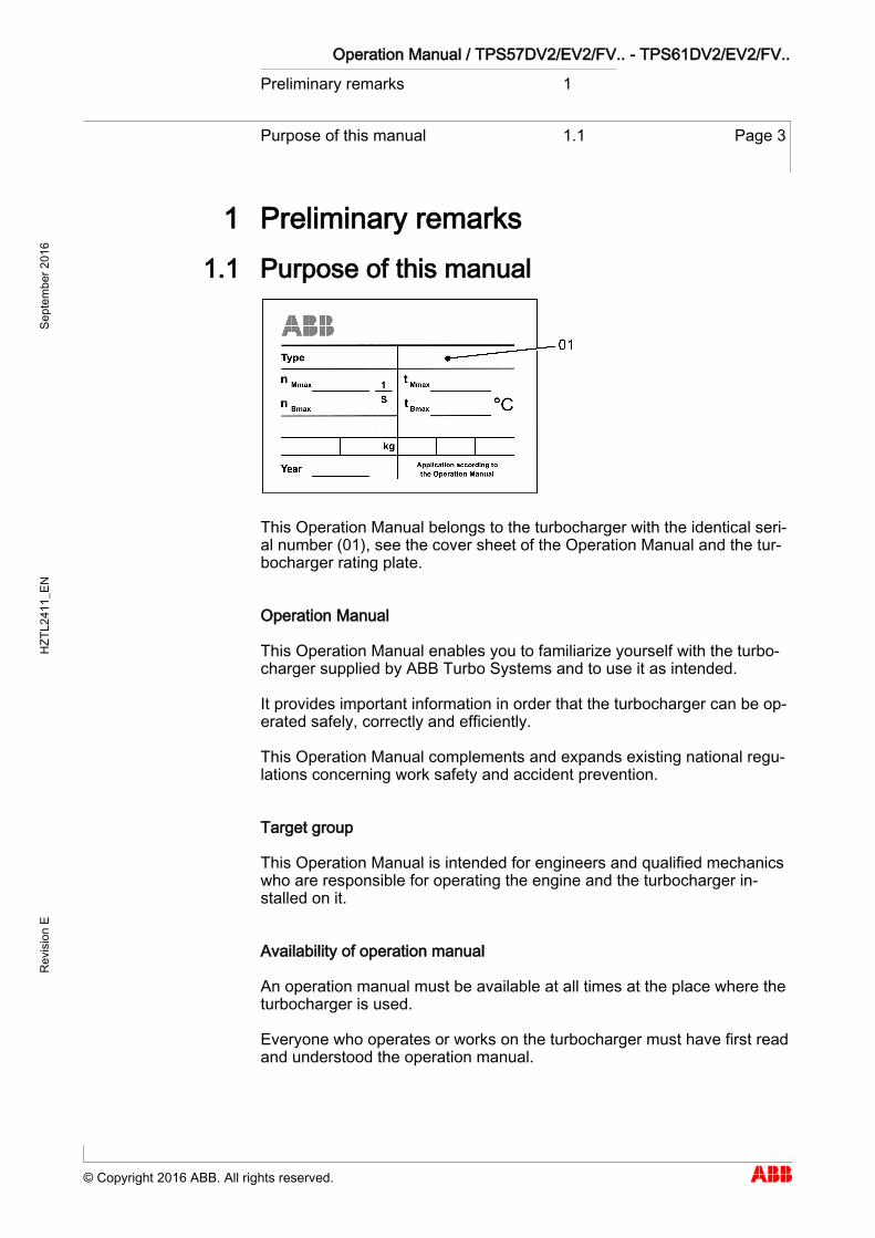
This Operation Manual belongs to the turbocharger with the identical seri-al number (01), see the cover sheet of the Operation Manual and the tur-bocharger rating plate.
Operation Manual
This Operation Manual enables you to familiarize yourself with the turbo-charger supplied by ABB Turbo Systems and to use it as intended.
It provides important information in order that the turbocharger can be op-erated safely, correctly and efficiently.
This Operation Manual complements and expands existing national regu-lations concerning work safety and accident prevention.
Target group
This Operation Manual is intended for engineers and qualified mechanics who are responsible for operating the engine and the turbocharger in-stalled on it.
Availability of operation manual
An operation manual must be available at all times at the place where the turbocharger is used.
Everyone who operates or works on the turbocharger must have first read and understood the operation manual.
1 1.1
Operation Manual / TPS57DV2/EV2/FV.. - TPS61DV2/EV2/FV.. Preliminary remarks 1
Layout and function 1.2 Page 4
© Copyright 2016 ABB. All rights reserved.
Sept
embe
r 201
6 H
ZTL2
411_
EN
Rev
isio
n E
Layout and function 1.2
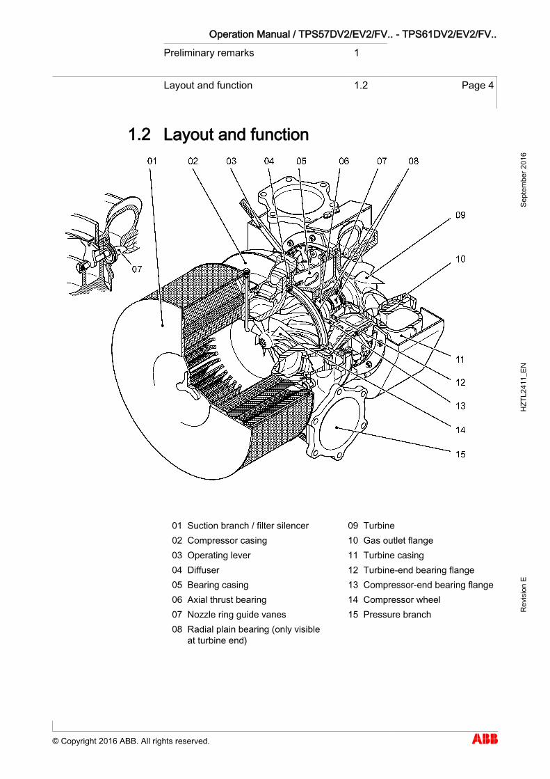
01 Suction branch / filter silencer 09 Turbine 02 Compressor casing 10 Gas outlet flange 03 Operating lever 11 Turbine casing 04 Diffuser 12 Turbine-end bearing flange 05 Bearing casing 13 Compressor-end bearing flange 06 Axial thrust bearing 14 Compressor wheel 07 Nozzle ring guide vanes 15 Pressure branch 08 Radial plain bearing (only visible
at turbine end)
1.2
Operation Manual / TPS57DV2/EV2/FV.. - TPS61DV2/EV2/FV.. Preliminary remarks 1
Layout and function 1.2 Page 5
© Copyright 2016 ABB. All rights reserved.
Sept
embe
r 201
6 H
ZTL2
411_
EN
Rev
isio
n E
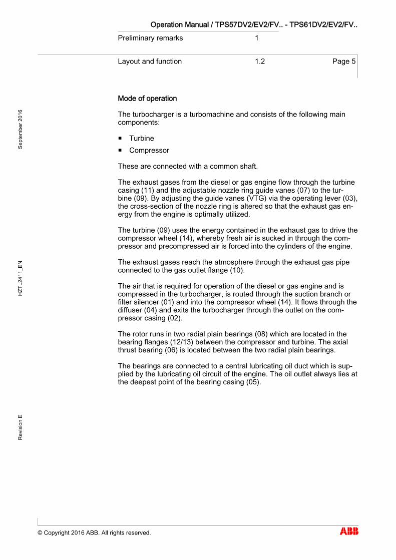
Mode of operation
The turbocharger is a turbomachine and consists of the following main components:
Turbine Compressor
These are connected with a common shaft.
The exhaust gases from the diesel or gas engine flow through the turbine casing (11) and the adjustable nozzle ring guide vanes (07) to the tur-bine (09). By adjusting the guide vanes (VTG) via the operating lever (03), the cross-section of the nozzle ring is altered so that the exhaust gas en-ergy from the engine is optimally utilized.
The turbine (09) uses the energy contained in the exhaust gas to drive the compressor wheel (14), whereby fresh air is sucked in through the com-pressor and precompressed air is forced into the cylinders of the engine.
The exhaust gases reach the atmosphere through the exhaust gas pipe connected to the gas outlet flange (10).
The air that is required for operation of the diesel or gas engine and is compressed in the turbocharger, is routed through the suction branch or filter silencer (01) and into the compressor wheel (14). It flows through the diffuser (04) and exits the turbocharger through the outlet on the com-pressor casing (02).
The rotor runs in two radial plain bearings (08) which are located in the bearing flanges (12/13) between the compressor and turbine. The axial thrust bearing (06) is located between the two radial plain bearings.
The bearings are connected to a central lubricating oil duct which is sup-plied by the lubricating oil circuit of the engine. The oil outlet always lies at the deepest point of the bearing casing (05).
Operation Manual / TPS57DV2/EV2/FV.. - TPS61DV2/EV2/FV.. Preliminary remarks 1
Intended use of the turbocharger 1.3 Page 6
© Copyright 2016 ABB. All rights reserved.
Sept
embe
r 201
6 H
ZTL2
411_
EN
Rev
isio
n E
Intended use of the turbocharger 1.3
NOTICE
This turbocharger supplied by ABB Turbo Systems has been developed for use on diesel engines to generate the volume of air and the charg-ing pressure required to operate the engine. The engine builder has provided ABB Turbo Systems with information regarding the intended use of the engine, from which the operating lim-its specific to the turbocharger shown on the rating plate (such as oper-ating speeds, temperatures, exchange intervals / replacement intervals) have been derived. If it is used in conjunction with a gas engine, the engine must not be in-stalled in a potentially explosive environment, and precautionary measures must be taken to ensure that the machine room as a whole is classified as not potentially explosive. Any other use will be regarded as a special application which must first be discussed with ABB Turbo Systems. The manufacturer accepts no liability for other applications. If it is used otherwise, ABB Turbo Sys-tems reserves the right to reject all warranty claims.
This turbocharger was built according to state-of-the-art technology and is operationally safe according to recognised safety regulations.
WARNING
Improper operation and maintenance of the turbocharger can result in danger to life and limb of the user or third parties. In addition, improper use may cause damage to the machine. The machine may be operated only by trained personnel.
Use of the turbocharger as intended also includes observance of the in-stallation / fitting, disassembly / removal, operating, maintenance / servic-ing and repair conditions specified by the manufacturer. Disposal regula-tions set down by local authorities must be observed.
The turbocharger may be installed only when in technically perfect condi-tion while observing the instructions given in the engine builder's manual. It may be used only for the intended purpose and operated in compliance with the operation manual.
Malfunctions which could affect safety must be eliminated immediately.
The manufacturer accepts no liability for any damage resulting from unau-thorised alterations to the turbocharger.
1.3
State of the art
Perfect condition

Operation Manual / TPS57DV2/EV2/FV.. - TPS61DV2/EV2/FV.. Preliminary remarks 1
Storage of new turbochargers and spare parts
1.4 Page 7
© Copyright 2016 ABB. All rights reserved.
Sept
embe
r 201
6 H
ZTL2
411_
EN
Rev
isio
n E
Storage of new turbochargers and spare parts 1.4
Storage of new turbochargers and spare parts up to 6 months
New turbochargers and spare parts from ABB Turbo Systems can be stored in sealed packaging without additional mothballing measures for up to 6 months from the date of delivery (marked by the VCI label on the package).
Volatile Corrosion Inhibitor (VCI)
Only dry rooms in which the relative humidity is between 40…70 % and no condensation can form are suitable for storage.
Storage of new turbochargers and spare parts for more than 6 months (VCI)
WARNING
Protection of health when handling VCIs VCI products are not hazardous in the sense of the Hazardous Sub-stances Ordinance. Nevertheless, the following points are to be ob-served when handling VCIs: Ensure good room ventilation. Do not eat, drink or keep food at the workplace while working with
VCIs. Wear safety gloves. Clean hands and face after working with VCIs. For further information refer to www.branopac.com.
Wear safety gloves to protect against chemical hazards.
The following mothballing measures are required every 6 months:
Open the package. Remove the VCI corrosion protection emitter from the package and
replace it with a new, identical VCI corrosion protection emitter. New VCI corrosion protection emitters can be obtained at www.branopac.com.
Dispose of the old VCI corrosion protection emitter in an environmen-tally compatible manner, professionally and in accordance with local regulations.
Seal the package. The better the external seal is designed, the more permanent the protection.
1.4
Operation Manual / TPS57DV2/EV2/FV.. - TPS61DV2/EV2/FV.. Preliminary remarks 1
Storage of new turbochargers and spare parts
1.4 Page 8
© Copyright 2016 ABB. All rights reserved.
Sept
embe
r 201
6 H
ZTL2
411_
EN
Rev
isio
n E
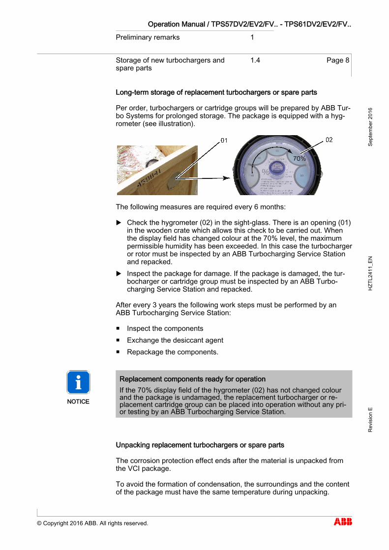
Long-term storage of replacement turbochargers or spare parts
Per order, turbochargers or cartridge groups will be prepared by ABB Tur-bo Systems for prolonged storage. The package is equipped with a hyg-rometer (see illustration).
The following measures are required every 6 months:
Check the hygrometer (02) in the sight-glass. There is an opening (01) in the wooden crate which allows this check to be carried out. When the display field has changed colour at the 70% level, the maximum permissible humidity has been exceeded. In this case the turbocharger or rotor must be inspected by an ABB Turbocharging Service Station and repacked.
Inspect the package for damage. If the package is damaged, the tur-bocharger or cartridge group must be inspected by an ABB Turbo-charging Service Station and repacked.
After every 3 years the following work steps must be performed by an ABB Turbocharging Service Station:
Inspect the components Exchange the desiccant agent Repackage the components.
NOTICE
Replacement components ready for operation If the 70% display field of the hygrometer (02) has not changed colour and the package is undamaged, the replacement turbocharger or re-placement cartridge group can be placed into operation without any pri-or testing by an ABB Turbocharging Service Station.
Unpacking replacement turbochargers or spare parts
The corrosion protection effect ends after the material is unpacked from the VCI package.
To avoid the formation of condensation, the surroundings and the content of the package must have the same temperature during unpacking.
Operation Manual / TPS57DV2/EV2/FV.. - TPS61DV2/EV2/FV.. Preliminary remarks 1
Essential information 1.5 Page 9
© Copyright 2016 ABB. All rights reserved.
Sept
embe
r 201
6 H
ZTL2
411_
EN
Rev
isio
n E
Essential information 1.5
Organisational measures
In addition to the Operation Manual, the general statutory regulations for the prevention of accidents and for environmental protection in the country of use must also be observed.
This also applies to the provision and wearing of personal protective equipment.
NOTICE
The manner in which personnel work on and with the turbocharger with regard to safety and risks is to be checked on a regular basis in ac-cordance with the Operation Manual.
The turbocharger must be shut down immediately in the event of modi-fications affecting safety or of corresponding operating behaviour by stopping the engine. The fault should be reported to the person or de-partment responsible.
NOTICE
Any modifications, additions or conversions made to the turbocharger, which could impair safety, require the prior approval of ABB Turbo Sys-tems.
1.5
Operation Manual / TPS57DV2/EV2/FV.. - TPS61DV2/EV2/FV.. Preliminary remarks 1
Essential information 1.5 Page 10
© Copyright 2016 ABB. All rights reserved.
Sept
embe
r 201
6 H
ZTL2
411_
EN
Rev
isio
n E
Original parts and safety
Original parts and accessories are specially designed for the turbocharger supplied by ABB Turbo Systems.
WARNING
Use original parts Operation of the turbocharger with non-original parts can impair the safety of the turbocharger and can cause serious damage to property and injury to personnel. Only use original parts from ABB Turbo Systems.
ABB Turbo Systems accepts no liability for any damage resulting from the use of non-original parts and corresponding accessories.
Competence of personnel
The turbocharger must only be operated and serviced by trained and au-thorised personnel. Basic mechanical training is a prerequisite.

Operation Manual / TPS57DV2/EV2/FV.. - TPS61DV2/EV2/FV.. Preliminary remarks 1
Essential information 1.5 Page 11
© Copyright 2016 ABB. All rights reserved.
Sept
embe
r 201
6 H
ZTL2
411_
EN
Rev
isio
n E
Design variants
This document is valid for different design variants of turbochargers. There may be sections and descriptions of components that are not rele-vant for a specific turbocharger variant.
ABB Turbocharging Service Stations will be happy to provide information on questions regarding a design variant (see Contact information at www.abb.com/turbocharging).
Accuracy of illustrations
The illustrations in this document are general in nature and intended for ease of understanding. Differences in detail are therefore possible.
Registered Trademarks
Registered trademarks of external companies are used in this document. The trademarks are marked with ®.
Operation Manual / TPS57DV2/EV2/FV.. - TPS61DV2/EV2/FV.. Preliminary remarks 1
Symbols and definitions 1.6 Page 12
© Copyright 2016 ABB. All rights reserved.
Sept
embe
r 201
6 H
ZTL2
411_
EN
Rev
isio
n E
Symbols and definitions 1.6
The following symbols are used in the documents:
Prerequisite Step of a procedure
List, first level
- List, second level
[➙ ] Refers to a page number
Definition of notes
NOTICE
Note A note provides suggestions which facilitate the work on the product.
Definition of mandatory signs
Mandatory signs show the protective equipment to be worn for a task. The mandatory signs are described in chapter Safety and must be complied with.
Definition of caution / warning
The caution and warning signs are described in the chapter Safety.
ABB Turbo Systems
In this document, ABB Turbo Systems Ltd is abbreviated to ABB Turbo Systems.
Official ABB Turbo Systems Service Stations
In this document, official service stations are referred to as ABB Turbo-charging Service Stations. They are inspected and certified regularly by ABB Turbo Systems. See also chapter Contact information [➙ 15].
1.6
Operation Manual / TPS57DV2/EV2/FV.. - TPS61DV2/EV2/FV.. Preliminary remarks 1
Turbocharger rating plate 1.7 Page 13
© Copyright 2016 ABB. All rights reserved.
Sept
embe
r 201
6 H
ZTL2
411_
EN
Rev
isio
n E
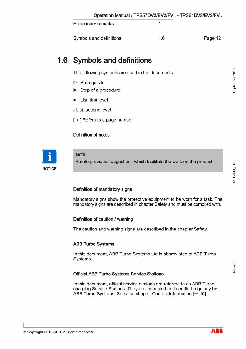
Turbocharger rating plate 1.7
01 Turbocharger operating limits at engine overload (110%). Only when operating in the test rig unless otherwise agreed with the enginebuilder.
02 Turbocharger operating limits during operation
03 Inspection interval of plain bearings in 1000 h 04 Replacement interval of compressor in 1000 h 05 Replacement interval of turbine in 1000 h
06 Customer part number 07 Designation of the special design 08 Weight of turbocharger in kg 09 Turbocharger type 10 Serial number 11 Year of construction of turbocharger
1.7
Operating limits
Recommended inspection and replacement intervals of turbocharger compo-nents
Further data
Operation Manual / TPS57DV2/EV2/FV.. - TPS61DV2/EV2/FV.. Preliminary remarks 1
Turbocharger rating plate 1.7 Page 14
© Copyright 2016 ABB. All rights reserved.
Sept
embe
r 201
6 H
ZTL2
411_
EN
Rev
isio
n E
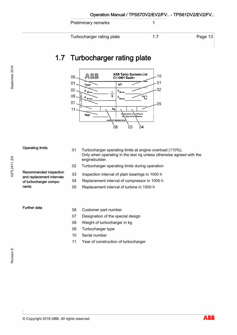
Explanation of the rating plate
The recommended replacement intervals and the corresponding opera-tional limits are jointly defined with the engine manufacturer. This informa-tion is specific to the system.
Operation above the indicated values nBmax, tBmax can considerably shorten the recommended replacement intervals. In such cases, we recommend that you contact the nearest official ABB Turbocharging service station. nMmaxand tMmax normally apply only when running at overload (110%) during tri-als on the engine test bed. These limits can also be permitted during operation for special applications. Operation above nMmax and tMmax is not permitted. Non-observance of the recommended replacement intervals can increase the risk of unpredictable component failures.
Positions of the rating plates
One rating plate (01) each is attached on the left and the right side of the turbocharger bearing casing.
1.7.1
1.7.2
Operation Manual / TPS57DV2/EV2/FV.. - TPS61DV2/EV2/FV.. Preliminary remarks 1
Contact information 1.8 Page 15
© Copyright 2016 ABB. All rights reserved.
Sept
embe
r 201
6 H
ZTL2
411_
EN
Rev
isio
n E
Contact information 1.8
Contact information
Contact information for the official service stations of ABB Turbo Systems is available online.
Scan the QR code to access our website.
ABB Turbo Systems Ltd Bruggerstrasse 71a CH-5401 Baden Switzerland www.abb.com/turbocharging
1.8

Operation Manual / TPS57DV2/EV2/FV.. - TPS61DV2/EV2/FV.. Safety 2
Introduction 2.1 Page 17
© Copyright 2016 ABB. All rights reserved.
Sept
embe
r 201
6 H
ZTL2
411_
EN
Rev
isio
n E
Safety
Introduction 2.1
Turbochargers manufactured by ABB Turbo Systems are state of the art and comply with the pertinent safety and health-protection requirements that applied when the turbocharger was manufactured. Consequently, the turbocharger is safe to operate. Nevertheless, during turbocharger opera-tion and when working on the turbocharger, residual risks can exist which:
originate from the turbocharger itself and its accessories originate from the operating and auxiliary materials used are the consequence of insufficient observance of the safety instruc-
tions are the consequence of unsatisfactory and improper execution of
maintenance and inspection work
The operator is responsible for access to the turbocharger as well as the organisational measures which regulate the safe handling of the turbo-charger by his personnel.
All instructions in this chapter must be observed to ensure safe and trou-ble-free turbocharger operation and during work on the turbocharger.
In the same vein, all other specially marked safety instructions in every chapter of this manual must be observed (see the section entitled Defini-tion of safety instructions).
2 2.1
Operation Manual / TPS57DV2/EV2/FV.. - TPS61DV2/EV2/FV.. Safety 2
CE conformity 2.2 Page 18
© Copyright 2016 ABB. All rights reserved.
Sept
embe
r 201
6 H
ZTL2
411_
EN
Rev
isio
n E
CE conformity 2.2
Information
ABB turbochargers fulfil Directive 2006/42/EC on machinery and are con-sidered partly completed machinery in the sense of Article 2 g.
2.2
Operation Manual / TPS57DV2/EV2/FV.. - TPS61DV2/EV2/FV.. Safety 2
Definition of mandatory signs 2.3 Page 19
© Copyright 2016 ABB. All rights reserved.
Sept
embe
r 201
6 H
ZTL2
411_
EN
Rev
isio
n E
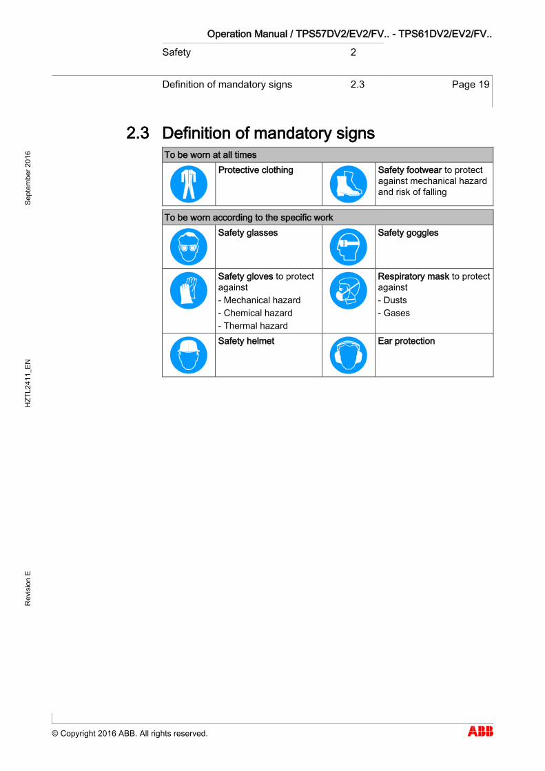
Definition of mandatory signs 2.3
To be worn at all times
Protective clothing
Safety footwear to protect against mechanical hazard and risk of falling
To be worn according to the specific work
Safety glasses
Safety goggles
Safety gloves to protect against - Mechanical hazard - Chemical hazard - Thermal hazard
Respiratory mask to protect against - Dusts - Gases
Safety helmet
Ear protection
2.3
Operation Manual / TPS57DV2/EV2/FV.. - TPS61DV2/EV2/FV.. Safety 2
Definition of Safety instructions 2.4 Page 20
© Copyright 2016 ABB. All rights reserved.
Sept
embe
r 201
6 H
ZTL2
411_
EN
Rev
isio
n E
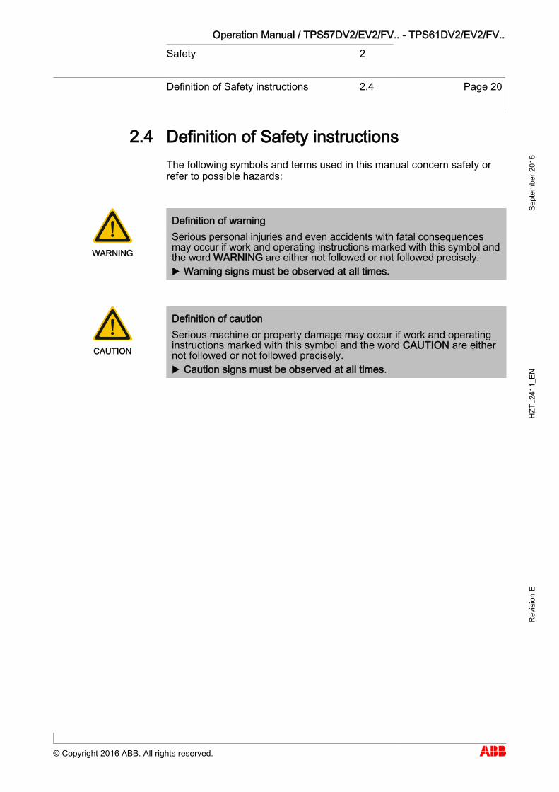
Definition of Safety instructions 2.4
The following symbols and terms used in this manual concern safety or refer to possible hazards:
WARNING
Definition of warning Serious personal injuries and even accidents with fatal consequences may occur if work and operating instructions marked with this symbol and the word WARNING are either not followed or not followed precisely. Warning signs must be observed at all times.
CAUTION
Definition of caution Serious machine or property damage may occur if work and operating instructions marked with this symbol and the word CAUTION are either not followed or not followed precisely. Caution signs must be observed at all times.
2.4

Operation Manual / TPS57DV2/EV2/FV.. - TPS61DV2/EV2/FV.. Safety 2
Warning plates on the turbocharger 2.5 Page 21
© Copyright 2016 ABB. All rights reserved.
Sept
embe
r 201
6 H
ZTL2
411_
EN
Rev
isio
n E
Warning plates on the turbocharger 2.5
Warning plates are attached to the turbocharger at the following places:
If warning plates are not present at the intended places or are not legible, then proceed as follows:
Order new warning plates from ABB Turbocharging Service Stations. Remove unreadable warning plates. Clean and degrease surfaces provided for warning plates. Attach new warning plates.
Uninsulated turbochargers
When uninsulated turbochargers are delivered to the engine builder, the warning plates must be subsequently attached to the insulation. This is the responsibility of the engine builder.
2.5
Operation Manual / TPS57DV2/EV2/FV.. - TPS61DV2/EV2/FV.. Safety 2
Safe operation and maintenance 2.6 Page 22
© Copyright 2016 ABB. All rights reserved.
Sept
embe
r 201
6 H
ZTL2
411_
EN
Rev
isio
n E
Safe operation and maintenance 2.6
The instructions specified in this section are for the safety of personnel. Together with the instructions in the Hazards during operation and maintenance section, they allow the user to safely use the turbocharger.
Work safety and work area safety
WARNING
Risk of falling There is the risk that someone can fall when working on the turbo-charger. Do not climb on the turbocharger or on parts attached to it or use
these as climbing aids. When working at levels above the head, use climbing aids and work
platforms suitable for this purpose.
Observe all general regulations for the prevention of accidents. Do not work on the turbocharger if you are under physical or mental
stress. Work only with suitable tools as well as equipment and working mate-
rials that are in perfect condition. Electric tools must be solidly earthed, and connecting cables may not
be damaged. Keep the workplace clean, clear away loose objects and remove ob-
stacles on the floor. Keep the floor, equipment and the turbocharger clean. Have oil binding materials ready at hand and keep oil catch pans
ready or in position Eliminate leaks. Keep fire-protection materials and fire-extinguishing equipment ready.
Welding work in the vicinity of the turbocharger
When performing welding work in the vicinity of the turbocharger, al-ways cover the filter silencer to prevent the filter mat from being dam-aged.
Keep flammable objects and substances out of the range of flying sparks.
Cover all connections on the turbocharger so that no foreign objects can enter the turbocharger.
Wear personal protective equipment (PPE) for welding operations.
2.6
Operation Manual / TPS57DV2/EV2/FV.. - TPS61DV2/EV2/FV.. Safety 2
Safe operation and maintenance 2.6 Page 23
© Copyright 2016 ABB. All rights reserved.
Sept
embe
r 201
6 H
ZTL2
411_
EN
Rev
isio
n E
Safety during start-up / commissioning and operation
Before starting work, carry out visual inspection of working area. Remove any obstacles and objects lying around. Before start-up / commissioning, check all pipes from and to turbo-
charger for damage and leaks. Don't work in any way that could impair safety when working on turbo-
charger. After about every 12 hours of operation or at least once a day, inspect
turbocharger for visible damage and defects. Immediately report any damage or changes in operational perfor-
mance to person responsible. If damage is discovered, immediately shut down turbocharger and se-
cure it against inadvertent or unauthorized use. When switching on auxiliary power sources (hydraulics, pneumatics,
electricity, water), keep an eye open for any hazards resulting from supplying these power sources.
Safety during cleaning
If cleaning agents or solvents are used for cleaning, the corresponding material safety data sheet and the safety instructions in section "Hazards due to operating and auxiliary materials" must be observed.
Observe the material safety data sheet for the cleaning agent or sol-vent.
Wear personal protective equipment (PPE) according to the material safety data sheet.
Inspect the electric cables for abrasion and damage before and after your cleaning work.
Operation Manual / TPS57DV2/EV2/FV.. - TPS61DV2/EV2/FV.. Safety 2
Safe operation and maintenance 2.6 Page 24
© Copyright 2016 ABB. All rights reserved.
Sept
embe
r 201
6 H
ZTL2
411_
EN
Rev
isio
n E
Safety during disassembly, assembly, maintenance and troubleshooting
Always perform the specified adjustments, servicing as well as inspec-tion work and observe inspection intervals.
Inform operating personnel about all service and repair work before beginning.
Before opening a cover or removing a protective device on a turbo-charger, the engine must be switched off and the turbocharger must have come to a standstill.
Ensure that the supply of oil is interrupted, especially with an external oil supply.
Put the engine into operation only after all parts have been refitted properly.
CAUTION
Mechanical work on the turbocharger Possible damage to or destruction of components on the turbocharger. Perform only those tasks that are described in this manual. Perform work only for which training has been carried out.
Safety when taking out of operation or preparing for mothballing
Secure the rotor so it cannot turn. The rotor can turn on its own from the force of the stack draught.
Clean the turbocharger before mothballing it. Observe the material safety data sheet for the cleaning and mothball-
ing agents. Wear personal protective equipment (PPE) according to the material
safety data sheet.
Operation Manual / TPS57DV2/EV2/FV.. - TPS61DV2/EV2/FV.. Safety 2
Hazards during operation and maintenance
2.7 Page 25
© Copyright 2016 ABB. All rights reserved.
Sept
embe
r 201
6 H
ZTL2
411_
EN
Rev
isio
n E
Hazards during operation and maintenance 2.7
Mechanical hazards during operation
During normal operation, no mechanical hazards emanate from the turbo-charger if it has been installed properly.
WARNING
Risk of injury Contact with rotating parts can lead to serious injuries. The turbo-charger must never be operated without a filter silencer or an air suction branch. When the engine is at a standstill, the rotor can turn on its own because of stack draught. Operate the turbocharger in accordance with instructions. During maintenance work, secure the rotor against unintentional ro-
tation.
Mechanical hazards when working on the turbocharger
During maintenance work, various risks can occur through the improper handling of components, through the non-observance of work instructions, due to inadequate care or as a consequence of insufficient training.
WARNING
Mechanical hazards Severe injuries to personnel or fatal accidents can be caused by me-chanical influences as a consequence of hazardous and inadequate operational procedures. Observe the general rules for occupational safety and prevention of
accidents. Ensure workplace safety. Only perform operations that are described in this document. Only perform operations for which you have previously received in-
struction or training.
2.7
Operation Manual / TPS57DV2/EV2/FV.. - TPS61DV2/EV2/FV.. Safety 2
Hazards during operation and maintenance
2.7 Page 26
© Copyright 2016 ABB. All rights reserved.
Sept
embe
r 201
6 H
ZTL2
411_
EN
Rev
isio
n E
Hazards due to noise
The development of noise during operation is influenced by the installation and operating conditions. Noise with a sound pressure level exceeding 85 dB(A) is harmful.
WARNING
Hazards due to noise Noise can cause impaired hearing, damage to health, mental disturb-ances, diminished attention and irritation. Always wear ear protection when the engine is running. When the sound pressure level is above 85 dB(A), always wear ear
protection.
Wear ear protection.
Hazards due to hot surfaces and substances
During operation, turbocharger surfaces and attached parts as well as op-erating materials (lubricating oil) become hot. The surface temperature is dependent on the effectiveness of the insulation being used. The tem-perature can become high enough so that it falls into ranges where burns are possible.
WARNING
Risk of burning Touching hot surfaces or contact with hot operating materials can lead to serious burns. Do not touch hot surfaces and heed the warning plate on the turbo-
charger. Wear heat-resistant safety gloves and protective clothing. Allow the turbocharger to cool down before carrying out any work.
Wear safety gloves to protect against thermal hazards.
Operation Manual / TPS57DV2/EV2/FV.. - TPS61DV2/EV2/FV.. Safety 2
Hazards during operation and maintenance
2.7 Page 27
© Copyright 2016 ABB. All rights reserved.
Sept
embe
r 201
6 H
ZTL2
411_
EN
Rev
isio
n E
WARNING
Hot surfaces on the non-insulated turbocharger Non-insulated turbochargers can cause serious injuries to personnel (burns). The turbocharger is supplied by ABB Turbo Systems without insulation depending on the order from the enginebuilder. If supply is without insu-lation, the enginebuilder is responsible for providing the turbocharger with proper insulation and for providing protection against contact with hot surfaces. Compliance with the instructions and specifications given by the en-
ginebuilder to protect against hot turbocharger surfaces is compulsory.
Wear safety gloves to protect against thermal hazards.
Hazards due to operating and auxiliary materials
Operating and auxiliary materials are substances used for operation or the execution of maintenance work. Oils, greases, coolants, cleaning agents and solvents, acids, etc. can be regarded as hazardous materials. Operat-ing and auxiliary materials can be combustible and easily ignited.
WARNING
Handling operating and auxiliary materials Ingestion or inhalation of vapours of operating and auxiliary materials or contact with such can cause damage to health. Avoid inhalation and contact with the skin. Ensure good ventilation. Observe details in the safety data sheets of the operating and auxil-
iary materials. Observe local laws.
Wear safety goggles.
Wear safety gloves to protect against chemical hazards.
Wear a respiratory mask to protect against gases.

Operation Manual / TPS57DV2/EV2/FV.. - TPS61DV2/EV2/FV.. Safety 2
Hazards during operation and maintenance
2.7 Page 28
© Copyright 2016 ABB. All rights reserved.
Sept
embe
r 201
6 H
ZTL2
411_
EN
Rev
isio
n E
WARNING
Risk of fire, explosion Flammable and combustible operating materials and supplies can catch fire or resulting vapours can lead to an explosion. Observe the details in the material safety data sheets of the operat-
ing and auxiliary materials. Comply with local legislation. Do not allow any exposed flame or ignition source during cleaning
work. Carry out cleaning in the open or provide sufficient aeration and ven-
tilation.
CAUTION
Risk of environmental damage The escape of operating and auxiliary materials into the atmosphere or contamination of the ground and water due to improper disposal can lead to environmental damage. Handle operating and auxiliary materials carefully.
Heed the instructions for use, safety data sheets and hazard notices on the containers of the operating and auxiliary materials.
Wear appropriate protective clothing. Avoid inhalation and contact with the skin. Ensure that the work space is adequately ventilated. Seal containers tightly immediately after use and put them away. Collect used working and auxiliary materials safely, store them sepa-
rately in suitable containers and dispose of them properly and in an environmentally compatible manner in accordance with statutory regu-lations.
In the event of leaks or after spilling, immediately spread a suitable binding agent and dispose of it properly and in an environmentally compatible manner in accordance with statutory regulations.
Operation Manual / TPS57DV2/EV2/FV.. - TPS61DV2/EV2/FV.. Safety 2
Hazards during operation and maintenance
2.7 Page 29
© Copyright 2016 ABB. All rights reserved.
Sept
embe
r 201
6 H
ZTL2
411_
EN
Rev
isio
n E
Hazards when handling insulating materials
WARNING
Hazards due to insulating materials Dust and fibres from insulating materials can cause damage to health or irritations. Unsuitable, combustible insulating materials signify a fire hazard. Use only suitable, non-combustible insulating materials. Ensure that the work area is well ventilated. Avoid stirring up dust. Use tools and processes which keep dust to a minimum. Remove packing materials only in the work area. Take particular care when removing old insulating materials. Dispose of insulating materials properly and in an environmentally
compatible way in accordance with applicable local regulations.
Wear safety goggles.
Wear a respiratory mask to protect against dusts.
Wear safety gloves to protect against chemical hazards.
Use only suitable, non-combustible insulating materials. Ensure that the work area is well ventilated. Wear suitable work clothing (safety glasses, respiratory mask). Avoid stirring up dust. Use tools and processes which keep dust to a minimum. Remove packing materials only in the work area. Take particular care when removing old insulating materials. Dispose of insulating materials properly and in an environmentally
compatible way in accordance with applicable local regulations.
Operation Manual / TPS57DV2/EV2/FV.. - TPS61DV2/EV2/FV.. Safety 2
Hazards during operation and maintenance
2.7 Page 30
© Copyright 2016 ABB. All rights reserved.
Sept
embe
r 201
6 H
ZTL2
411_
EN
Rev
isio
n E
Hazards due to electrical components
WARNING
Hazards due to electrical components Electrical components operate with voltages which can present hazards to humans. All work on or with electrical components may only be performed by
trained specialists. Heed any country-specific regulations.
Operation Manual / TPS57DV2/EV2/FV.. - TPS61DV2/EV2/FV.. Safety 2
Deflagration on gas engines 2.8 Page 31
© Copyright 2016 ABB. All rights reserved.
Sept
embe
r 201
6 H
ZTL2
411_
EN
Rev
isio
n E
Deflagration on gas engines 2.8
ABB turbochargers can tolerate a deflagration with a transient pressure increase of 12 bar.
After a deflagration event ABB Turbo Systems recommends verifying the following points on the turbocharger:
Position of the turbine and compressor casings to the bearing casing Shifting of the bearing casing in relation to the bracket Cracks in casings
If during external inspection anomalies are found or if a particularly strong deflagration event has taken place, it is also recommended to check the bearings of the turbochargers before the next start. This inspection and evaluation must be carried out by an ABB Turbocharging Service Station.
2.8
Operation Manual / TPS57DV2/EV2/FV.. - TPS61DV2/EV2/FV.. Safety 2
Periodic checking of the pressure vessel
2.9 Page 32
© Copyright 2016 ABB. All rights reserved.
Sept
embe
r 201
6 H
ZTL2
411_
EN
Rev
isio
n E
Periodic checking of the pressure vessel 2.9
The pressure vessels used by ABB Turbo Systems, such as those for wet or dry cleaning, are so-called "simple pressure vessels".
The local, statutory regulations covering periodic checks of pressure vessels must be observed.
The operator is responsible for the safe operation of the pressure vessel.
WARNING
Hazards from pressure vessels The operator must keep the pressure vessel in a proper condition and monitor it. Necessary repair or maintenance work must be carried out without delay and the required safety precautions must be taken. Pressure equipment must not be operated if it has defects.
2.9

Operation Manual / TPS57DV2/EV2/FV.. - TPS61DV2/EV2/FV.. Safety 2
Lifting loads 2.10 Page 33
© Copyright 2016 ABB. All rights reserved.
Sept
embe
r 201
6 H
ZTL2
411_
EN
Rev
isio
n E
Lifting loads 2.10
WARNING
Suspended loads Loads not suspended in compliance with regulations may lead to per-sonal injury or accidents with fatal consequences. Loads must always be fastened to technically perfect lifting gear with
sufficient loading capacity. Make sure the load is suspended properly on the crane hook. Do not let anyone stand beneath a suspended load.
Wear safety gloves to protect against mechanical hazards.
Wear safety helmet.
In the case of two or more suspension points, the slinging angle must not exceed 45°. This avoids excessive loading due to inclined tensile loading.
Fasten turbocharger assemblies / components as described in respec-tive handling steps.
Before attaching slings, allow turbocharger components to cool down (maximum 80°C).
Use suitable protection at sharp edges. Completely screw in assembly / fitting devices without fail so that they
cannot work loose during use. Use assembly / fitting devices only for applications described. Make sure removed turbocharger components stand safely and se-
curely.
2.10

Operation Manual / TPS57DV2/EV2/FV.. - TPS61DV2/EV2/FV.. Commissioning 3
Oil supply 3.1 Page 35
© Copyright 2016 ABB. All rights reserved.
Sept
embe
r 201
6 H
ZTL2
411_
EN
Rev
isio
n E
Commissioning
Oil supply 3.1
A carefully designed and installed oil supply, which functions in all possi-ble operational conditions, is an important prerequisite for trouble-free tur-bocharger operation.
The turbocharger is normally lubricated with oil from the engine oil circuit. If a separate lubricating system is used, then emergency lubrication is al-so to be provided.
Heed the instructions of the engine builder when selecting the lubricat-ing oil and oil-change intervals.
Oil filtration
CAUTION
Depending on the turbine specifications and bearings used, varying amounts of contaminants have to be filtered out of the lubricating oil to avoid dangerous wear of the bearing parts.
The standard oil filter specification for the turbocharger is 34 µm. This means that contaminants larger than 0.034 mm must be filtered out of the oil with a separation efficiency > 99%.
Fit an accessory filter if engine oil filter is not efficient enough. If the engine is started cold and the flow resistance rises to above
0.5 bar due to deposits of dirt in the accessory filter, a bypass must open which ensures that oil flows to the turbocharger by circumventing the filter.
Check that oil filters are clean before commissioning.
NOTICE
Also follow the enginebuilder's instructions regarding filter mesh and separation efficiency.
3 3.1
Operation Manual / TPS57DV2/EV2/FV.. - TPS61DV2/EV2/FV.. Commissioning 3
Oil supply 3.1 Page 36
© Copyright 2016 ABB. All rights reserved.
Sept
embe
r 201
6 H
ZTL2
411_
EN
Rev
isio
n E
Lubricant
NOTICE
All lubricating oils used for engines are admissible.
Oil inlet viscosity and temperature
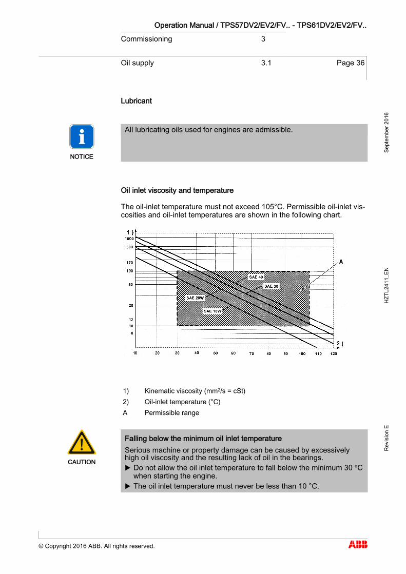
The oil-inlet temperature must not exceed 105°C. Permissible oil-inlet vis-cosities and oil-inlet temperatures are shown in the following chart.
1) Kinematic viscosity (mm2/s = cSt) 2) Oil-inlet temperature (°C) A Permissible range
CAUTION
Falling below the minimum oil inlet temperature Serious machine or property damage can be caused by excessively high oil viscosity and the resulting lack of oil in the bearings. Do not allow the oil inlet temperature to fall below the minimum 30 ºC
when starting the engine. The oil inlet temperature must never be less than 10 °C.
Operation Manual / TPS57DV2/EV2/FV.. - TPS61DV2/EV2/FV.. Commissioning 3
Oil supply 3.1 Page 37
© Copyright 2016 ABB. All rights reserved.
Sept
embe
r 201
6 H
ZTL2
411_
EN
Rev
isio
n E
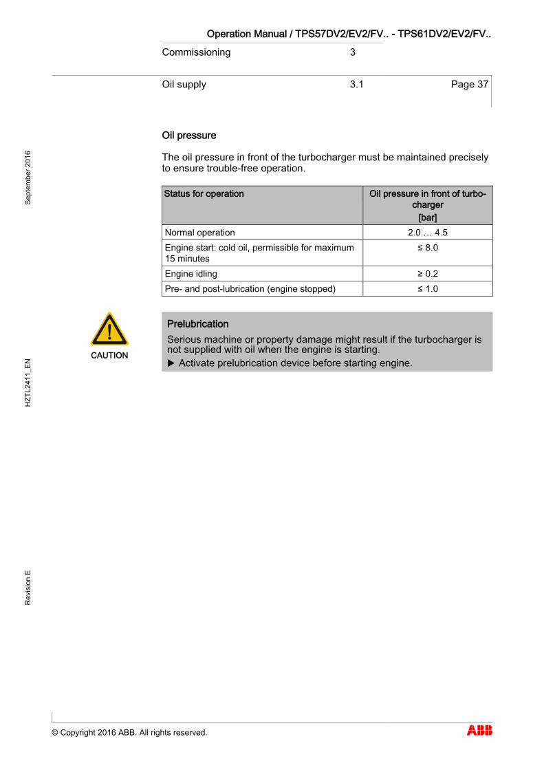
Oil pressure
The oil pressure in front of the turbocharger must be maintained precisely to ensure trouble-free operation.
Status for operation Oil pressure in front of turbo-charger
[bar] Normal operation 2.0 … 4.5 Engine start: cold oil, permissible for maximum 15 minutes
≤ 8.0
Engine idling ≥ 0.2 Pre- and post-lubrication (engine stopped) ≤ 1.0
CAUTION
Prelubrication Serious machine or property damage might result if the turbocharger is not supplied with oil when the engine is starting. Activate prelubrication device before starting engine.
Operation Manual / TPS57DV2/EV2/FV.. - TPS61DV2/EV2/FV.. Commissioning 3
Oil supply 3.1 Page 38
© Copyright 2016 ABB. All rights reserved.
Sept
embe
r 201
6 H
ZTL2
411_
EN
Rev
isio
n E
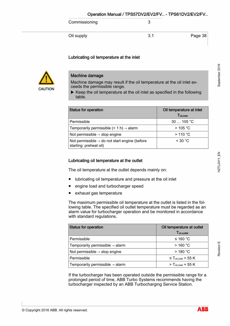
Lubricating oil temperature at the inlet
CAUTION
Machine damage Machine damage may result if the oil temperature at the oil inlet ex-ceeds the permissible range. Keep the oil temperature at the oil inlet as specified in the following
table.
Status for operation Oil temperature at inlet Toil,inlet
Permissible 30 … 105 °C Temporarily permissible (< 1 h) → alarm > 105 °C Not permissible → stop engine > 110 °C Not permissible → do not start engine (before starting: preheat oil)
< 30 °C
Lubricating oil temperature at the outlet
The oil temperature at the outlet depends mainly on:
lubricating oil temperature and pressure at the oil inlet engine load and turbocharger speed exhaust gas temperature
The maximum permissible oil temperature at the outlet is listed in the fol-lowing table. The specified oil outlet temperature must be regarded as an alarm value for turbocharger operation and be monitored in accordance with standard regulations.
Status for operation Oil temperature at outlet Toil,outlet
Permissible ≤ 160 °C Temporarily permissible → alarm > 160 °C Not permissible → stop engine > 180 °C Permissible ≤ Toil,inlet + 55 K Temporarily permissible → alarm > Toil,inlet + 55 K
If the turbocharger has been operated outside the permissible range for a prolonged period of time, ABB Turbo Systems recommends having the turbocharger inspected by an ABB Turbocharging Service Station.
Operation Manual / TPS57DV2/EV2/FV.. - TPS61DV2/EV2/FV.. Commissioning 3
Inspection work 3.2 Page 39
© Copyright 2016 ABB. All rights reserved.
Sept
embe
r 201
6 H
ZTL2
411_
EN
Rev
isio
n E
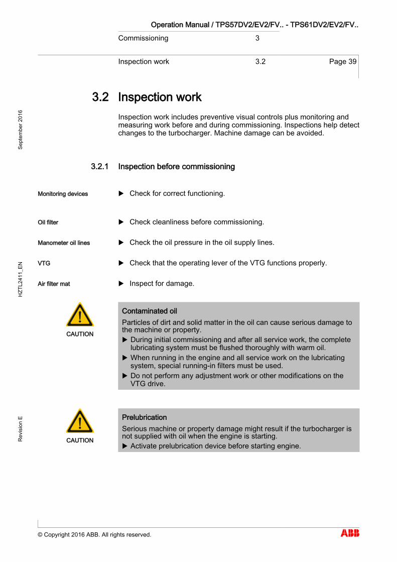
Inspection work 3.2
Inspection work includes preventive visual controls plus monitoring and measuring work before and during commissioning. Inspections help detect changes to the turbocharger. Machine damage can be avoided.
Inspection before commissioning
Check for correct functioning.
Check cleanliness before commissioning.
Check the oil pressure in the oil supply lines.
Check that the operating lever of the VTG functions properly.
Inspect for damage.
CAUTION
Contaminated oil Particles of dirt and solid matter in the oil can cause serious damage to the machine or property. During initial commissioning and after all service work, the complete
lubricating system must be flushed thoroughly with warm oil. When running in the engine and all service work on the lubricating
system, special running-in filters must be used. Do not perform any adjustment work or other modifications on the
VTG drive.
CAUTION
Prelubrication Serious machine or property damage might result if the turbocharger is not supplied with oil when the engine is starting. Activate prelubrication device before starting engine.
3.2
3.2.1
Monitoring devices
Oil filter
Manometer oil lines
VTG
Air filter mat

Operation Manual / TPS57DV2/EV2/FV.. - TPS61DV2/EV2/FV.. Commissioning 3
Inspection work 3.2 Page 40
© Copyright 2016 ABB. All rights reserved.
Sept
embe
r 201
6 H
ZTL2
411_
EN
Rev
isio
n E
Check after start-up (engine at idling speed)
Measure (optional, a turbocharger speed gauge is not standard equipment on all turbocharger types)
Measure
Measure in front of and after the turbine, compressor and oil feed at various engine outputs.
Check the VTG operating lever's control functionality
Check all gas, air and oil lines for leaks after starting the engine.
Measure the speed, oil pressure, charging pressure and temperatures in front of and after the turbine and compressor at various levels of engine performance.
Compare measured values with values in the acceptance test report, taking into account different operating conditions.
3.2.2
Turbocharger speed
Charging pressure
Temperatures
VTG
Gas, air and oil lines
Operation Manual / TPS57DV2/EV2/FV.. - TPS61DV2/EV2/FV.. Commissioning 3
Inspection work 3.2 Page 41
© Copyright 2016 ABB. All rights reserved.
Sept
embe
r 201
6 H
ZTL2
411_
EN
Rev
isio
n E
Check when running up engine
Measure speed, oil pressure and charging pressure at various engine performance levels.
Measure exhaust gas temperature in front of and behind turbine. Measure air temperature in front of and behind compressor.
The measured values must be compared with the values in the acceptance test report, while taking different operating conditions into account.
NOTICE
Lubricants and pastes used during assembly of the turbocharger liquefy or vaporise and might escape as an oily liquid in the first few hours after commissioning. If oily liquid continues to escape after this period, an oil leak must be suspected. The first step is to check for leakage of the oil supply to the turbocharger. If this is leaky, contact an official ABB Tur-bocharging service station.
Inspection after 100 service hours
Clean or replace lubricating oil filters after the first 100 service hours.
3.2.3
3.2.4
Operation Manual / TPS57DV2/EV2/FV.. - TPS61DV2/EV2/FV.. Commissioning 3
Commissioning after taking out of operation
3.3 Page 42
© Copyright 2016 ABB. All rights reserved.
Sept
embe
r 201
6 H
ZTL2
411_
EN
Rev
isio
n E
Commissioning after taking out of operation 3.3
Remove cover plates (blind flanges) between compressor casing out-let and charge air duct, before gas inlet and after gas outlet.
Inspect exhaust gas duct / line in front of and after turbine for any combustion deposits, foreign matter or residual water. Clean and re-move.
Inspect air supply line or filter silencer for any foreign matter. Clean and remove.
Start up turbocharger oil circulation system at engine end. Prepare turbocharger for operation as instructed in section "Inspection
work before start-up / commissioning" of chapter headed "Start-up / commissioning".
Start up turbocharger.
3.3 If provided

Operation Manual / TPS57DV2/EV2/FV.. - TPS61DV2/EV2/FV.. Operation 4
Noise emissions 4.1 Page 43
© Copyright 2016 ABB. All rights reserved.
Sept
embe
r 201
6 H
ZTL2
411_
EN
Rev
isio
n E
Operation
Noise emissions 4.1
WARNING
Hazards due to noise Noise can cause impaired hearing, damage to health, mental disturb-ances, diminished attention and irritation. Always wear ear protection when the engine is running. When the sound pressure level is above 85 dB(A), always wear ear
protection.
Wear ear protection.
The sound pressure level (A-weighted) of emissions is measured at a dis-tance of 1 metre from the turbocharger.
The highest sound pressure level of emissions1) reaches a maximum of 105 dB(A) near the filter silencer and over the entire speed range.
The following prerequisites must be fulfilled on the turbocharger in order to observe this limit value:
Fitted air-inlet system All standard, noise-reducing measures have been taken2). The bellows at the air outlet have been perfectly insulated acoustically
by the engine builder. He is also responsible for insulating the charge air / scavenging air line and the charge air cooler.
1) Directive 2006/42/EC, 1.7.4.2 / u / Paragraphs 5 + 7 : A-weighted emission sound pressure level
2) In the event of divergent insulation designs, the engine builder must en-sure that equivalent acoustic insulating measures are taken.
4 4.1
Operation Manual / TPS57DV2/EV2/FV.. - TPS61DV2/EV2/FV.. Operation 4
Noise emissions 4.1 Page 44
© Copyright 2016 ABB. All rights reserved.
Sept
embe
r 201
6 H
ZTL2
411_
EN
Rev
isio
n E
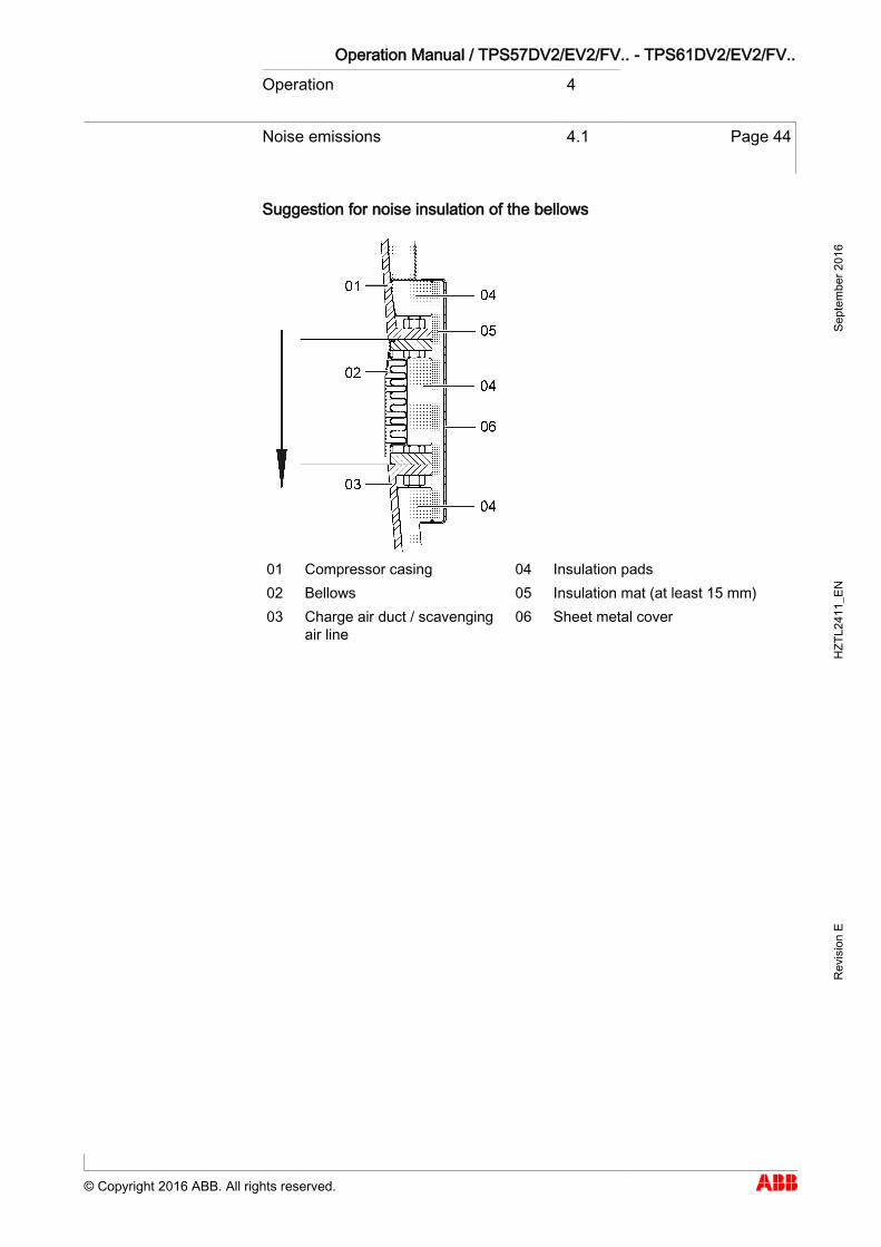
Suggestion for noise insulation of the bellows
01 Compressor casing 04 Insulation pads 02 Bellows 05 Insulation mat (at least 15 mm) 03 Charge air duct / scavenging
air line 06 Sheet metal cover
Operation Manual / TPS57DV2/EV2/FV.. - TPS61DV2/EV2/FV.. Operation 4
Servicing work 4.2 Page 45
© Copyright 2016 ABB. All rights reserved.
Sept
embe
r 201
6 H
ZTL2
411_
EN
Rev
isio
n E
Servicing work 4.2
Service work to be carried out during operation involves visual checks, monitoring, measuring, inspection work and functional checks. It is then possible for changes to the turbocharger to be identified and rectified. In this way, it can be ensured that the turbocharger remains in full working order.
CAUTION
Service intervals Service work on the turbocharger that is neglected or carried out too late can lead to excessive contamination and wear as well as operating failures. Carry out service work at specified time intervals.
CAUTION
Shortened service intervals Despite observance of the service intervals, unusual loads, such as several start-stops a day, harsh environmental factors, poor fuel quality or heavy installation vibration can lead to premature machine damage. A shortened service interval must be arranged with ABB Turbo Sys-
tems.
NOTICE
Service inspection after 5 years To prevent age- and stoppage-related machine damage, an inspection by an ABB Turbocharging Service Station is recommended at the latest 5 years after the last service.
Service work every 25 … 50 hours
Visual inspection for air, exhaust gas, water and oil leaks. Record operating data and enter it in the engine logbook. Clarify the cause of any variances.
CAUTION
Unknown changes during operation The consequences can range from an impairment to a breakdown. Have unknown causes clarified by an ABB Turbocharging service
station.
4.2
4.2.1
Operation Manual / TPS57DV2/EV2/FV.. - TPS61DV2/EV2/FV.. Operation 4
Servicing work 4.2 Page 46
© Copyright 2016 ABB. All rights reserved.
Sept
embe
r 201
6 H
ZTL2
411_
EN
Rev
isio
n E
Servicing work according to the engine manufacturer's instructions
Clean or replace oil filter in supply line to turbocharger when engine is not running.
Service work in accordance with instructions on rating plate
(In general, after 8000 - 12000 hours of operation)
Rotor and bearing parts must be inspected and assessed by an ABB Tur-bocharging Service Station. The following work can be carried in prepara-tion.
Remove cartridge group as described in chapter Disassembly and as-sembly.
Measure clearances. Clean turbine and compressor casings and check them for cracks and
erosion / corrosion. Clean bearing casing and blow air through oil ports / holes.
Service work every 15000 hours
Have a variable turbine geometry module replaced with an overhauled module by an ABB Turbocharger service station. For such cases, ABB Turbo Systems offers replacement modules as part of the CPEX pro-gram (Customer Part Exchange).
Variable turbine geometry modules are transported fitted to the bearing casing.
4.2.2
Oil filter
4.2.3
4.2.4
Operation Manual / TPS57DV2/EV2/FV.. - TPS61DV2/EV2/FV.. Operation 4
Servicing work 4.2 Page 47
© Copyright 2016 ABB. All rights reserved.
Sept
embe
r 201
6 H
ZTL2
411_
EN
Rev
isio
n E
Entries in engine logbook
By monitoring the engine, conclusions can be drawn about the turbo-charger performance.
The following operating data and measured values must be entered regu-larly in the engine manufacturer's engine logbook:
Engine performance and speed Air intake temperature Exhaust gas temperature in front of and behind the turbine Pressure of charge air Pressure drop in charge air cooler Lubricating oil pressure and lubricating oil temperature
Air temperature behind compressor and charge air cooler Turbocharger speed Pressure loss in air filter
4.2.5
If provided
Operation Manual / TPS57DV2/EV2/FV.. - TPS61DV2/EV2/FV.. Operation 4
Expected exchange intervals 4.3 Page 48
© Copyright 2016 ABB. All rights reserved.
Sept
embe
r 201
6 H
ZTL2
411_
EN
Rev
isio
n E
Expected exchange intervals 4.3
Rotating components
The recommended replacement intervals for compressor wheels and tur-bine wheels are defined depending on the operating conditions and based on the safety concept (SiKo) for rotating parts. These intervals can be found on the turbocharger rating plate.
Non-rotating components
Depending on the system-specific operating conditions, a distinction is made between:
the replacement interval for the bearing parts and the replacement interval for those non-rotating components that are
exposed to hot gases.
Decisive in this respect are various influencing parameters, which can drastically shorten the replacement intervals of these parts in extreme cases.
During the specified periodic service work, the individual components are inspected for wear and, if necessary, replaced.
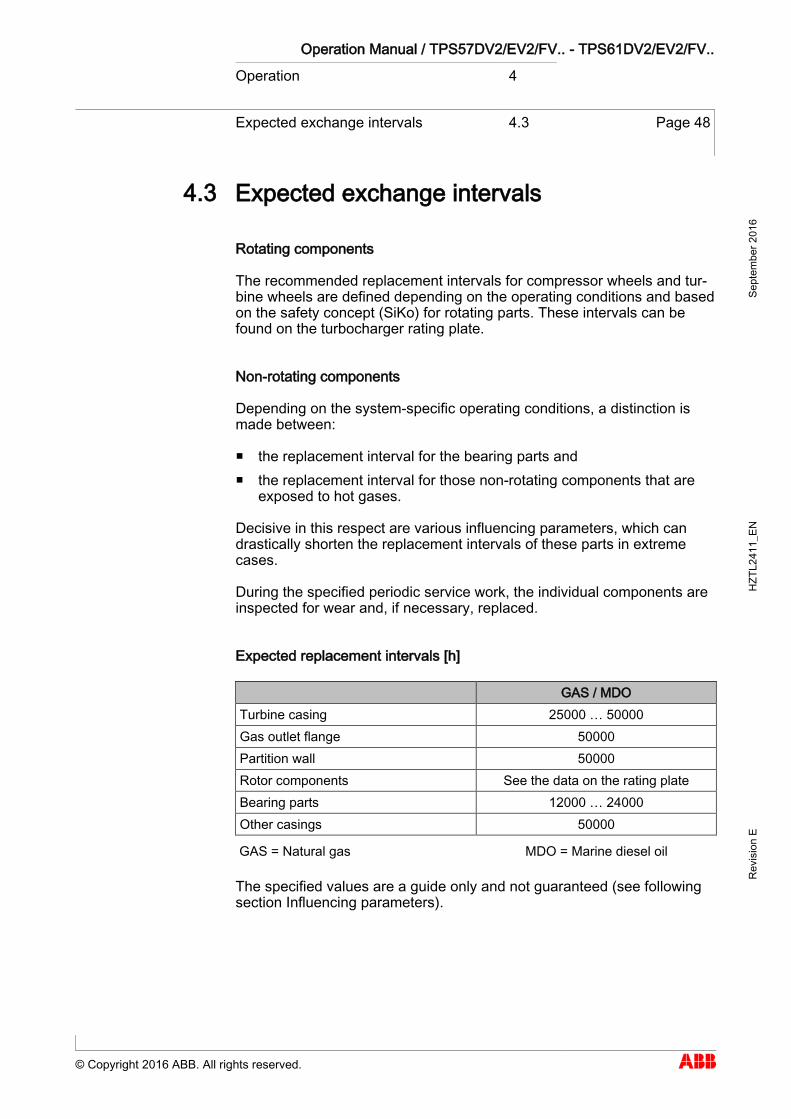
Expected replacement intervals [h]
GAS / MDO Turbine casing 25000 … 50000 Gas outlet flange 50000 Partition wall 50000 Rotor components See the data on the rating plate Bearing parts 12000 … 24000 Other casings 50000
GAS = Natural gas MDO = Marine diesel oil
The specified values are a guide only and not guaranteed (see following section Influencing parameters).
4.3
Operation Manual / TPS57DV2/EV2/FV.. - TPS61DV2/EV2/FV.. Operation 4
Expected exchange intervals 4.3 Page 49
© Copyright 2016 ABB. All rights reserved.
Sept
embe
r 201
6 H
ZTL2
411_
EN
Rev
isio
n E
Influencing parameters
The specified values are only guide values and not guaranteed. The actu-al values can deviate considerably from the guide values due, for exam-ple, to the following influences:
Fuel quality and preparation Load profile (thermal load cycles, also starts / stops, emergency shut-
downs) Gas inlet temperature Frequency and execution of turbine and compressor cleaning Turbocharger specification System-specific operating conditions (operating point, combustion
quality, composition of exhaust gas)
For bearing parts
Lubricating oil quality (oil filtration, condition of lubricating oil, oil moni-toring)
Load profile (rpm / speed, pressure conditions, temperature) State of rotor unbalance (degree of contamination)
Operation Manual / TPS57DV2/EV2/FV.. - TPS61DV2/EV2/FV.. Operation 4
Speed measurement 4.4 Page 50
© Copyright 2016 ABB. All rights reserved.
Sept
embe
r 201
6 H
ZTL2
411_
EN
Rev
isio
n E
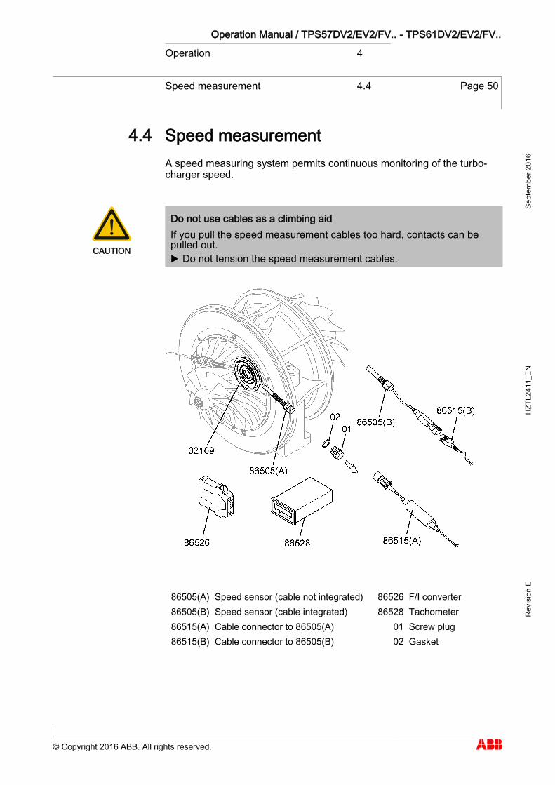
Speed measurement 4.4
A speed measuring system permits continuous monitoring of the turbo-charger speed.
CAUTION
Do not use cables as a climbing aid If you pull the speed measurement cables too hard, contacts can be pulled out. Do not tension the speed measurement cables.
86505(A) Speed sensor (cable not integrated) 86526 F/I converter 86505(B) Speed sensor (cable integrated) 86528 Tachometer 86515(A) Cable connector to 86505(A) 01 Screw plug 86515(B) Cable connector to 86505(B) 02 Gasket
4.4
Operation Manual / TPS57DV2/EV2/FV.. - TPS61DV2/EV2/FV.. Operation 4
Speed measurement 4.4 Page 51
© Copyright 2016 ABB. All rights reserved.
Sept
embe
r 201
6 H
ZTL2
411_
EN
Rev
isio
n E
Speed differences with multiple turbochargers per engine
The speeds of all turbochargers on one engine differ only slightly from each other in normal operation.
The difference between the highest and the lowest turbocharger speed must not be more than 3 % relative to the speed limit nBmax.
If this permissible range of difference is exceeded, the following steps must be carried out:
Reduce engine performance immediately until the highest turbo-charger speed no longer exceeds 70% of nBmax.
If the engine cannot be stopped, continue to run at this reduced engine performance or turbocharger speed.
If the turbocharger surges continuously, engine performance must be reduced further.
Measure the temperatures in the air and gas lines to and from the tur-bochargers and compare them with standard values.
If the engine can be stopped for a short time:
Inspect the air and gas lines as well as the turbocharger and eliminate any problems.
In any event, it is recommended that you contact the nearest ABB Turbocharging Service Station.
4.4.1
Operation Manual / TPS57DV2/EV2/FV.. - TPS61DV2/EV2/FV.. Operation 4
Speed measurement 4.4 Page 52
© Copyright 2016 ABB. All rights reserved.
Sept
embe
r 201
6 H
ZTL2
411_
EN
Rev
isio
n E
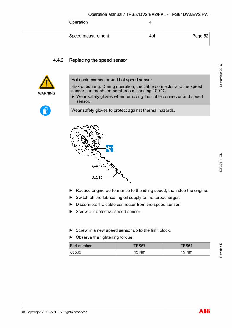
Replacing the speed sensor
WARNING
Hot cable connector and hot speed sensor Risk of burning. During operation, the cable connector and the speed sensor can reach temperatures exceeding 100 °C. Wear safety gloves when removing the cable connector and speed
sensor.
Wear safety gloves to protect against thermal hazards.
Reduce engine performance to the idling speed, then stop the engine. Switch off the lubricating oil supply to the turbocharger. Disconnect the cable connector from the speed sensor. Screw out defective speed sensor.
Screw in a new speed sensor up to the limit block. Observe the tightening torque.
Part number TPS57 TPS61 86505 15 Nm 15 Nm
4.4.2
Operation Manual / TPS57DV2/EV2/FV.. - TPS61DV2/EV2/FV.. Operation 4
Speed measurement 4.4 Page 53
© Copyright 2016 ABB. All rights reserved.
Sept
embe
r 201
6 H
ZTL2
411_
EN
Rev
isio
n E
NOTICE
Sealing the speed sensor The speed sensor is designed with a sealing lip and does not require an additional gasket when fitted.
Connect cable connector to speed sensor. Switch on lubricating oil supply to turbocharger.
Failure of speed measuring system
Possible reasons for failure of the speed measuring system are described in the chapter Troubleshooting.
4.4.3
Operation Manual / TPS57DV2/EV2/FV.. - TPS61DV2/EV2/FV.. Operation 4
Stopping the engine 4.5 Page 54
© Copyright 2016 ABB. All rights reserved.
Sept
embe
r 201
6 H
ZTL2
411_
EN
Rev
isio
n E
Stopping the engine 4.5
CAUTION
Stopping the engine of oil-cooled turbocharger version Heat in the turbocharger must be dissipated by the further circulating lubricating oil. Post-lubricate for 15 … 20 minutes. Maintain oil pressure of 0.5 … 1.0 bar for post-lubrication.
4.5
Operation Manual / TPS57DV2/EV2/FV.. - TPS61DV2/EV2/FV.. Maintenance 5
Foreword to Maintenance 5.1 Page 55
© Copyright 2016 ABB. All rights reserved.
Sept
embe
r 201
6 H
ZTL2
411_
EN
Rev
isio
n E
Maintenance
Foreword to Maintenance 5.1
General maintenance work involves regular visual checks and cleaning tasks which are intended to ensure the trouble-free functioning of the tur-bocharger.
The cleaning points described in the following are:
filter silencer compressor
5 5.1

Operation Manual / TPS57DV2/EV2/FV.. - TPS61DV2/EV2/FV.. Maintenance 5
Cleaning the filter silencer 5.2 Page 56
© Copyright 2016 ABB. All rights reserved.
Sept
embe
r 201
6 H
ZTL2
411_
EN
Rev
isio
n E
Cleaning the filter silencer 5.2
81135 Filter silencer body 81266 Cover grid 81136 Absorption segment 81270 Tension band 81137 Sheet-metal covering 81271 Lock 81265 Filter ring
NOTICE
Disassembly and assembly The procedure for disassembly and assembly of the filter silencer is de-scribed in the chapter entitled Disassembly and Assembly.
Cleaning the filter ring (if provided)
Remove filter ring (81265). Clean filter ring (81265) as required or every 500 operating hours, and
replace after the fifth cleaning operation at the latest. The degree of contamination of the filter ring depends on the cleanli-ness of the air that is drawn in.
Wash filter ring (81265) using water containing light-duty detergent or, if very heavily contaminated, soak it while squeezing carefully. Rinse in cold water. Avoid rough handling (do not use a water jet).
Allow the filter ring to dry out completely before assembly. Dispose of dirty water and gentle detergents in accordance with valid
local regulations.
5.2
Operation Manual / TPS57DV2/EV2/FV.. - TPS61DV2/EV2/FV.. Maintenance 5
Cleaning the filter silencer 5.2 Page 57
© Copyright 2016 ABB. All rights reserved.
Sept
embe
r 201
6 H
ZTL2
411_
EN
Rev
isio
n E
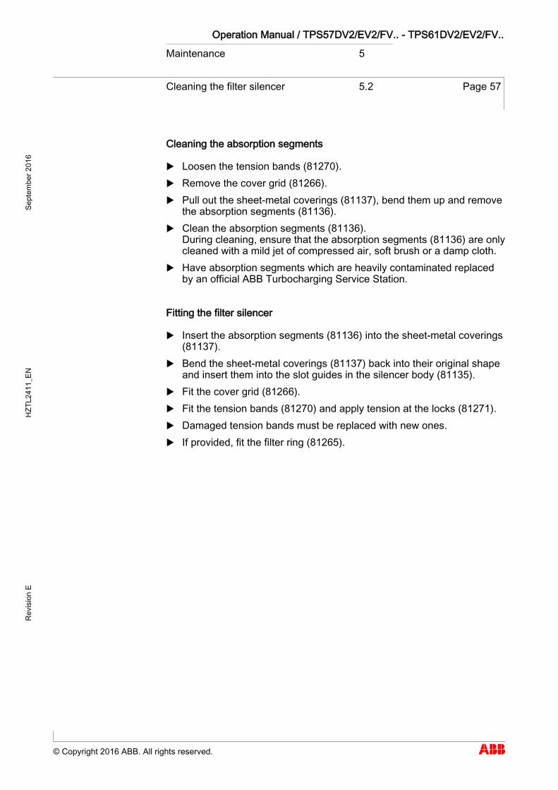
Cleaning the absorption segments
Loosen the tension bands (81270). Remove the cover grid (81266). Pull out the sheet-metal coverings (81137), bend them up and remove
the absorption segments (81136). Clean the absorption segments (81136).
During cleaning, ensure that the absorption segments (81136) are only cleaned with a mild jet of compressed air, soft brush or a damp cloth.
Have absorption segments which are heavily contaminated replaced by an official ABB Turbocharging Service Station.
Fitting the filter silencer
Insert the absorption segments (81136) into the sheet-metal coverings (81137).
Bend the sheet-metal coverings (81137) back into their original shape and insert them into the slot guides in the silencer body (81135).
Fit the cover grid (81266). Fit the tension bands (81270) and apply tension at the locks (81271). Damaged tension bands must be replaced with new ones. If provided, fit the filter ring (81265).
Operation Manual / TPS57DV2/EV2/FV.. - TPS61DV2/EV2/FV.. Maintenance 5
Cleaning the compressor during operation
5.3 Page 58
© Copyright 2016 ABB. All rights reserved.
Sept
embe
r 201
6 H
ZTL2
411_
EN
Rev
isio
n E
Cleaning the compressor during operation 5.3
The contamination of the compressor stage (compressor wheel, wall in-sert and diffuser) depends on the degree of purity of the taken-in air.
Deposits can form in the flow channels if salt, oil mist, exhaust gas or dust are sucked in with the air.
Consequences of contamination:
Impaired compressor efficiency Higher exhaust gas temperatures Increased fuel consumption Increased rotor unbalance
Periodic cleaning of the compressor during operation prevents or delays any major increase in contamination. But it never replaces the regular service work where the turbocharger is completely dismantled and the compressor is mechanically cleaned.
NOTICE
If the coating of dirt is very thick and hard, the compressor can only be cleaned manually when disassembled. This cleaning must be carried out by an ABB Turbocharging Service Station.
The interval between periodic cleaning is very dependent on the operating conditions. In general, cleaning should be carried out every 25 ... 100 op-erating hours.
Should the specified cleaning intervals prove incompatible with engine operation, please contact ABB Turbo Systems.
5.3 General
Cleaning interval
Operation Manual / TPS57DV2/EV2/FV.. - TPS61DV2/EV2/FV.. Maintenance 5
Cleaning the compressor during operation
5.3 Page 59
© Copyright 2016 ABB. All rights reserved.
Sept
embe
r 201
6 H
ZTL2
411_
EN
Rev
isio
n E
Cleaning method
Cleaning the compressor while in operation is carried out as wet cleaning. This cleaning method has been tested and approved by ABB Turbo Sys-tems.
To clean the compressor stage during operation, water is injected in front of the compressor wheel through an injection pipe fitted in the filter silenc-er or the suction branch.
The water does not act as a solvent, but the dirt deposit is removed by the mechanical impact of the droplets. This is a very suitable process, provid-ed that the degree of contamination is not too high.
CAUTION
Corrosion and deposits when cleaning Damage and impairment of turbocharger parts due to salt water and cooling water additives Don't use salt water for cleaning, but only clean fresh water.
CAUTION
The injection pipe must on no account be connected directly via a cock to a water pipe or a dosing vessel larger than the one supplied. This prevents uncontrolled volumes of water entering the turbocharger and engine, which can lead to serious damage.
In the case of V-engines with several turbochargers on each engine, we recommend parallel cleaning of the compressors. This cleaning process is faster and the risk of turbocharger surging is reduced.
In the case of sequential charging, care must be taken to ensure that tur-bocharger compressors are cleaned regularly, especially after periods of operation in the lower performance range.
Principle of wet cleaning
V-engines
Sequential charging
Operation Manual / TPS57DV2/EV2/FV.. - TPS61DV2/EV2/FV.. Maintenance 5
Cleaning the compressor during operation
5.3 Page 60
© Copyright 2016 ABB. All rights reserved.
Sept
embe
r 201
6 H
ZTL2
411_
EN
Rev
isio
n E
Wet cleaning compressor using external water pressure vessel (XC1)
These instructions for wet cleaning only apply when cleaning is carried out with clean water and under the precondition that the enginebuilder ap-proves the process.
NOTICE
Supplying water from the externally mounted water vessel is suitable only for those applications where a negative pressure exists in front of the compressor wheel (not used for: blowers connected in front of the compressor or high-pressure compressor stages with two-stage charg-ing).
Operating state prerequisites for cleaning compressor with XC1
NOTICE
To be able to carry out a satisfactory cleaning process that has been tested and is recommended by ABB Turbo Systems, the following pre-requisites must be fulfilled: Run engine at load from 50 … 85 %. Start cleaning cycle according to following description Wet cleaning
operation with XC1.
5.3.1
Approval by enginebuilder
Operation Manual / TPS57DV2/EV2/FV.. - TPS61DV2/EV2/FV.. Maintenance 5
Cleaning the compressor during operation
5.3 Page 61
© Copyright 2016 ABB. All rights reserved.
Sept
embe
r 201
6 H
ZTL2
411_
EN
Rev
isio
n E
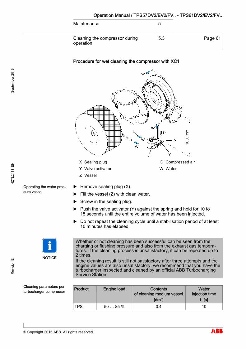
Procedure for wet cleaning the compressor with XC1
X Sealing plug D Compressed air Y Valve activator W Water Z Vessel
Remove sealing plug (X). Fill the vessel (Z) with clean water. Screw in the sealing plug. Push the valve activator (Y) against the spring and hold for 10 to
15 seconds until the entire volume of water has been injected. Do not repeat the cleaning cycle until a stabilisation period of at least
10 minutes has elapsed.
NOTICE
Whether or not cleaning has been successful can be seen from the charging or flushing pressure and also from the exhaust gas tempera-tures. If the cleaning process is unsatisfactory, it can be repeated up to 2 times. If the cleaning result is still not satisfactory after three attempts and the engine values are also unsatisfactory, we recommend that you have the turbocharger inspected and cleaned by an official ABB Turbocharging Service Station.
Product Engine load Contents of cleaning medium vessel
[dm3]
Water injection time
t1 [s] TPS 50 … 85 % 0.4 10
Operating the water pres-sure vessel
Cleaning parameters per turbocharger compressor


Operation Manual / TPS57DV2/EV2/FV.. - TPS61DV2/EV2/FV.. Troubleshooting 6
Malfunctions when starting 6.1 Page 63
© Copyright 2016 ABB. All rights reserved.
Sept
embe
r 201
6 H
ZTL2
411_
EN
Rev
isio
n E
Troubleshooting
Malfunctions when starting 6.1
Sluggish start-up
Possible causes Elimination Turbo-charger
Dirty turbocharger Clean it Damaged bearing Contact an ABB Turbocharging
Service Station Rubbing rotor Foreign object in turbocharger VTG module damaged or dirty Clean it or contact an ABB Tur-
bocharging Service Station
Vibrations
Possible causes Elimination Turbo-charger
Rotor unbalance Contact an ABB Turbocharging Service Station Damaged turbine or compressor
Damaged bearing
Rubbing of rotating parts
Normal behaviour, no malfunction Turbo-charger
Minor uniform wear around the periphery of rotor components, caused by slight local rubbing of adjacent components, is permis-sible. The compressor blades and turbine blades are then short-ened somewhat. Certain tolerances must be observed to avoid a significant loss of efficiency. If there is any doubt about the extent of rubbing, then an ABB
Turbocharging Service Station must be contacted. Have a dimension check carried out by an ABB Turbocharging
Service Station.
6 6.1
Operation Manual / TPS57DV2/EV2/FV.. - TPS61DV2/EV2/FV.. Troubleshooting 6
Surging of the turbocharger 6.2 Page 64
© Copyright 2016 ABB. All rights reserved.
Sept
embe
r 201
6 H
ZTL2
411_
EN
Rev
isio
n E
Surging of the turbocharger 6.2
Turbocharger surging
Possible causes Elimination Engine Guard in front of the turbo-
charger is dirty or damaged Clean / replace it
Turbo-charger
Filter silencer or diffuser dirty Clean it Heavy deposits of dirt in the turbine or nozzle ring VTG or VTG mechanism de-fective
Contact an ABB Turbocharging Service Station
Charge air cooler
Dirty cooler Clean it Charge air duct blocked
CAUTION
Prolonged or periodic surging Possible damage to components, such as the compressor wheel, tur-bine blades, bearings and filter silencer Have the cause clarified immediately by an ABB Turbocharging ser-
vice station and rectified. Have components inspected for damage and, if necessary, replaced
by an ABB Turbocharging service station.
Sporadic surge blows
Surging of the turbocharger can occur during certain operating conditions such as when reducing the engine performance quickly when manoeu-vring. At the same time, the flow direction in the compressor is momentari-ly reversed. Such sporadic surge blows do not impair the safe operation of the turbocharger.
A surge blow is accompanied by a loud bang and escape of hot air from the filter silencer.
6.2
Operation Manual / TPS57DV2/EV2/FV.. - TPS61DV2/EV2/FV.. Troubleshooting 6
Malfunctions during operation 6.3 Page 65
© Copyright 2016 ABB. All rights reserved.
Sept
embe
r 201
6 H
ZTL2
411_
EN
Rev
isio
n E
Malfunctions during operation 6.3
Lubricating oil pressure too low
Possible causes Elimination Engine Oil filter heavily contaminated Clean it
Defective oil pump in lubricating system
Check / replace it
Manometer display wrong Replace the manometer Turbo-charger
Rotor axial clearance too large Contact an ABB Turbocharging Service Station
Reduction in speed
Possible causes Elimination Engine Defects of connected cylinders
when pulse charging Contact the engine builder
Turbo-charger
Heavy contamination in the tur-bine
Clean it
Damaged rotor components or bearing
Contact an ABB Turbocharging Service Station
VTG module damaged or dirty Clean it or contact an ABB Tur-bocharging Service Station
Pipes Defects such as leaks in the ex-haust gas pipes or charge air ducts
Make repairs
Increase in speed
Possible causes Elimination Turbo-charger
Very dirty turbine (with 4-stroke application)
Contact an ABB Turbocharging Service Station
VTG module damaged or dirty Clean it or contact an ABB Tur-bocharging Service Station
6.3
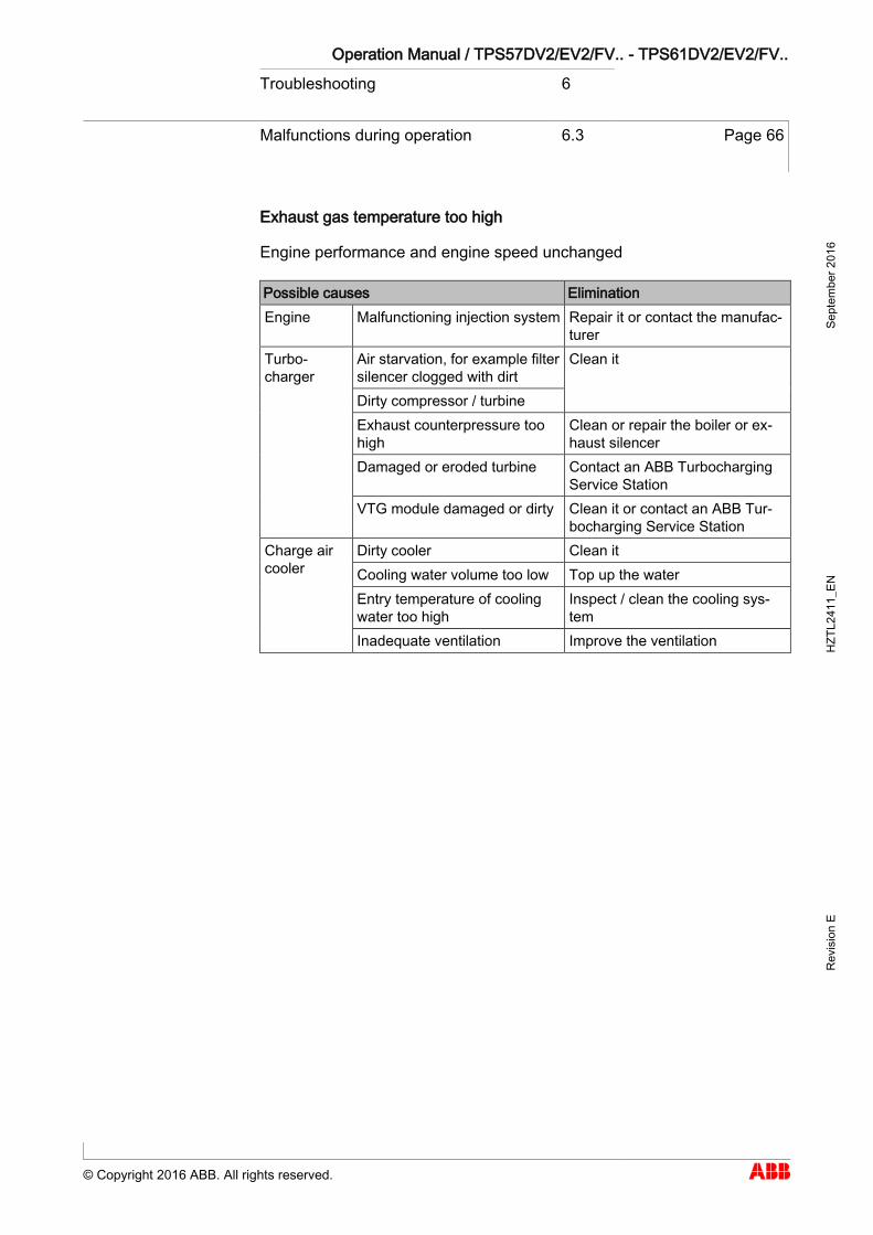
Operation Manual / TPS57DV2/EV2/FV.. - TPS61DV2/EV2/FV.. Troubleshooting 6
Malfunctions during operation 6.3 Page 66
© Copyright 2016 ABB. All rights reserved.
Sept
embe
r 201
6 H
ZTL2
411_
EN
Rev
isio
n E
Exhaust gas temperature too high
Engine performance and engine speed unchanged
Possible causes Elimination Engine Malfunctioning injection system Repair it or contact the manufac-
turer Turbo-charger
Air starvation, for example filter silencer clogged with dirt
Clean it
Dirty compressor / turbine Exhaust counterpressure too high
Clean or repair the boiler or ex-haust silencer
Damaged or eroded turbine Contact an ABB Turbocharging Service Station
VTG module damaged or dirty Clean it or contact an ABB Tur-bocharging Service Station
Charge air cooler
Dirty cooler Clean it Cooling water volume too low Top up the water Entry temperature of cooling water too high
Inspect / clean the cooling sys-tem
Inadequate ventilation Improve the ventilation
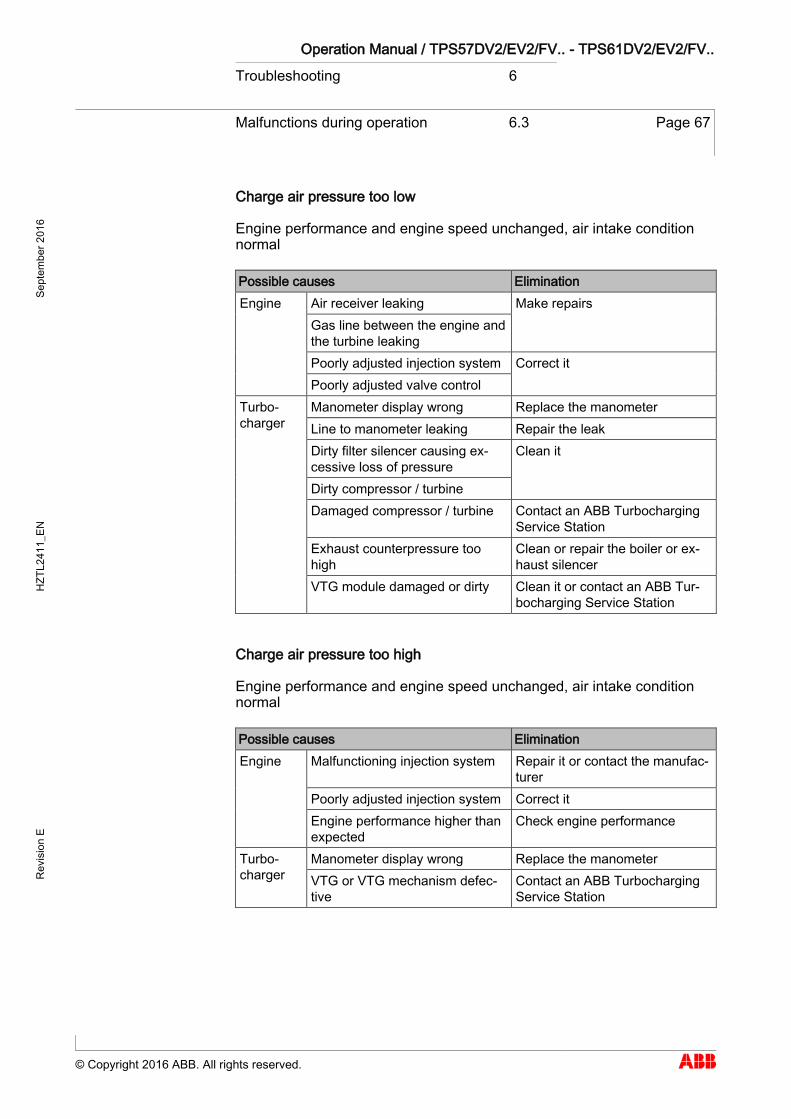
Operation Manual / TPS57DV2/EV2/FV.. - TPS61DV2/EV2/FV.. Troubleshooting 6
Malfunctions during operation 6.3 Page 67
© Copyright 2016 ABB. All rights reserved.
Sept
embe
r 201
6 H
ZTL2
411_
EN
Rev
isio
n E
Charge air pressure too low
Engine performance and engine speed unchanged, air intake condition normal
Possible causes Elimination Engine Air receiver leaking Make repairs
Gas line between the engine and the turbine leaking Poorly adjusted injection system Correct it Poorly adjusted valve control
Turbo-charger
Manometer display wrong Replace the manometer Line to manometer leaking Repair the leak Dirty filter silencer causing ex-cessive loss of pressure
Clean it
Dirty compressor / turbine Damaged compressor / turbine Contact an ABB Turbocharging
Service Station Exhaust counterpressure too high
Clean or repair the boiler or ex-haust silencer
VTG module damaged or dirty Clean it or contact an ABB Tur-bocharging Service Station
Charge air pressure too high
Engine performance and engine speed unchanged, air intake condition normal
Possible causes Elimination Engine Malfunctioning injection system Repair it or contact the manufac-
turer Poorly adjusted injection system Correct it Engine performance higher than expected
Check engine performance
Turbo-charger
Manometer display wrong Replace the manometer VTG or VTG mechanism defec-tive
Contact an ABB Turbocharging Service Station
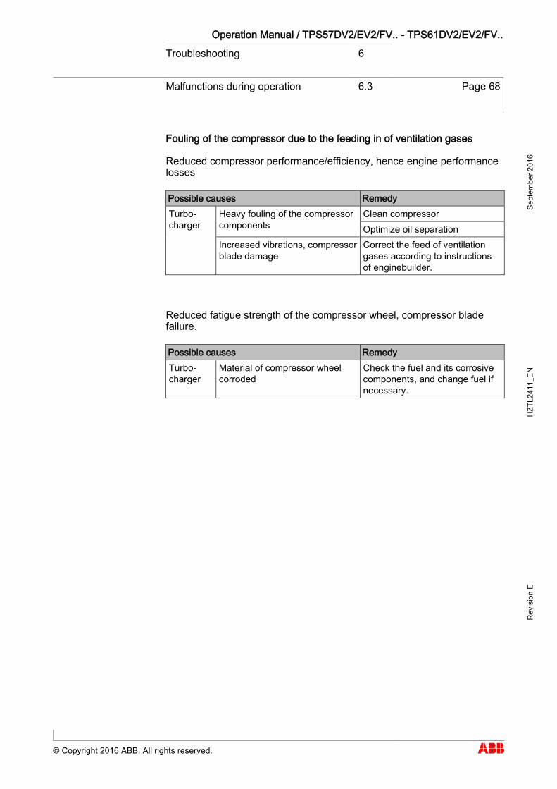
Operation Manual / TPS57DV2/EV2/FV.. - TPS61DV2/EV2/FV.. Troubleshooting 6
Malfunctions during operation 6.3 Page 68
© Copyright 2016 ABB. All rights reserved.
Sept
embe
r 201
6 H
ZTL2
411_
EN
Rev
isio
n E
Fouling of the compressor due to the feeding in of ventilation gases
Reduced compressor performance/efficiency, hence engine performance losses
Possible causes Remedy Turbo-charger
Heavy fouling of the compressor components
Clean compressor Optimize oil separation
Increased vibrations, compressor blade damage
Correct the feed of ventilation gases according to instructions of enginebuilder.
Reduced fatigue strength of the compressor wheel, compressor blade failure.
Possible causes Remedy Turbo-charger
Material of compressor wheel corroded
Check the fuel and its corrosive components, and change fuel if necessary.
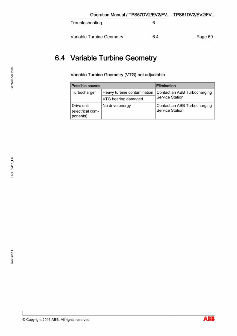
Operation Manual / TPS57DV2/EV2/FV.. - TPS61DV2/EV2/FV.. Troubleshooting 6
Variable Turbine Geometry 6.4 Page 69
© Copyright 2016 ABB. All rights reserved.
Sept
embe
r 201
6 H
ZTL2
411_
EN
Rev
isio
n E
Variable Turbine Geometry 6.4
Variable Turbine Geometry (VTG) not adjustable
Possible causes Elimination Turbocharger Heavy turbine contamination Contact an ABB Turbocharging
Service Station VTG bearing damaged Drive unit (electrical com-ponents)
No drive energy Contact an ABB Turbocharging Service Station
6.4

Operation Manual / TPS57DV2/EV2/FV.. - TPS61DV2/EV2/FV.. Troubleshooting 6
Malfunctions when stopping 6.5 Page 70
© Copyright 2016 ABB. All rights reserved.
Sept
embe
r 201
6 H
ZTL2
411_
EN
Rev
isio
n E
Malfunctions when stopping 6.5
Noises during run-down
Possible causes Elimination Turbo-charger
Turbocharger contaminated Clean it Damaged bearing Contact an ABB Turbocharging
Service Station Rubbing rotor Foreign object in turbocharger
Run-down time too short
Possible causes Elimination Turbo-charger
Turbocharger contaminated Clean it Damaged bearing Contact an ABB Turbocharging
Service Station Rubbing rotor Foreign object in turbocharger
6.5

Operation Manual / TPS57DV2/EV2/FV.. - TPS61DV2/EV2/FV.. Troubleshooting 6
Speed measurement system 6.6 Page 71
© Copyright 2016 ABB. All rights reserved.
Sept
embe
r 201
6 H
ZTL2
411_
EN
Rev
isio
n E
Speed measurement system 6.6
Possible causes Elimination No signal or amplitude is poor
Fitting error
The screw plug for the sensor is fitted with an additional gasket (copper ring). When fitting the speed sensor, this gasket must be removed. If the gasket is fitted by mistake, the distance from the sensor tip to the signal-generating sealing disc increases. As a result, the voltage amplitude of the speed signal decreases, which can cause problems for the evaluation electronics. This problem is eliminated by removing the gasket.
Defective sensor Contact an ABB Turbocharging Service Sta-tion
Measured speeds too high
Contaminated sensor tip
The sensor tip is magnetic and can thus at-tract metal particles. As a result, the dis-tance to the signal-generating sealing disc is reduced, which can lead to amplification of the noise component and consequently to faulty triggering. Dismantle the sensor, clean its tip and refit the sensor using the specified tightening torque.
Measured speed too low
- - Contact an ABB Turbocharging Service Sta-tion
Other sources of errors
- - If none of the above measures eliminates the malfunction, we recommend that you have the speed measuring system inspected by an ABB Turbocharging Service Station.
6.6

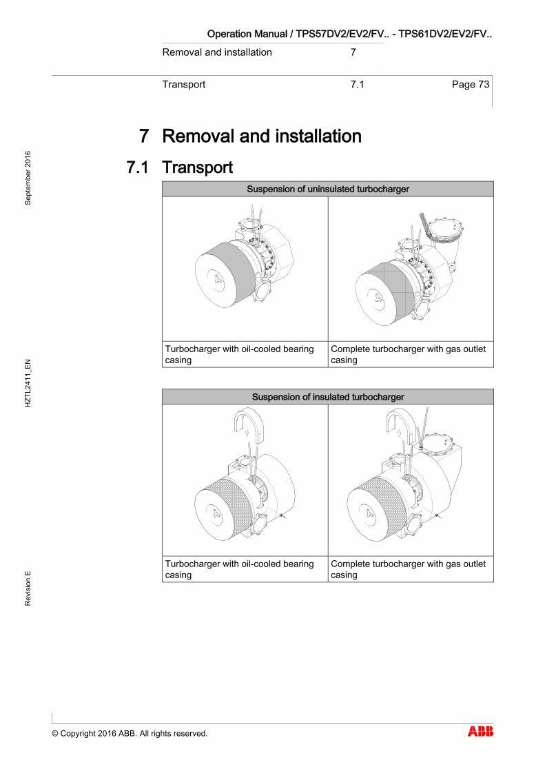
Operation Manual / TPS57DV2/EV2/FV.. - TPS61DV2/EV2/FV.. Removal and installation 7
Transport 7.1 Page 73
© Copyright 2016 ABB. All rights reserved.
Sept
embe
r 201
6 H
ZTL2
411_
EN
Rev
isio
n E
Removal and installation
Transport 7.1
Suspension of uninsulated turbocharger
Turbocharger with oil-cooled bearing casing
Complete turbocharger with gas outlet casing
Suspension of insulated turbocharger
Turbocharger with oil-cooled bearing casing
Complete turbocharger with gas outlet casing
7 7.1
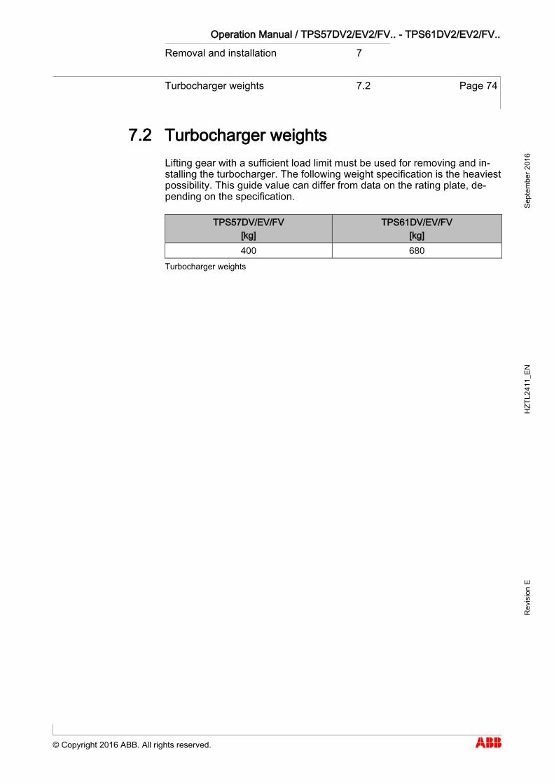
Operation Manual / TPS57DV2/EV2/FV.. - TPS61DV2/EV2/FV.. Removal and installation 7
Turbocharger weights 7.2 Page 74
© Copyright 2016 ABB. All rights reserved.
Sept
embe
r 201
6 H
ZTL2
411_
EN
Rev
isio
n E
Turbocharger weights 7.2
Lifting gear with a sufficient load limit must be used for removing and in-stalling the turbocharger. The following weight specification is the heaviest possibility. This guide value can differ from data on the rating plate, de-pending on the specification.
TPS57DV/EV/FV [kg]
TPS61DV/EV/FV [kg]
400 680
Turbocharger weights
7.2

Operation Manual / TPS57DV2/EV2/FV.. - TPS61DV2/EV2/FV.. Removal and installation 7
Remove the turbocharger 7.3 Page 75
© Copyright 2016 ABB. All rights reserved.
Sept
embe
r 201
6 H
ZTL2
411_
EN
Rev
isio
n E
Remove the turbocharger 7.3
Mark assembled position of operating lever and separate VTG drive from operating lever.
Disconnect all exhaust gas and air lines according to the instructions of the enginebuilder.
Version with water-cooled bearing casing:
Disconnect the water pipes according to the instructions of the en-ginebuilder.
If present, remove hard insulation as follows:
Remove screws and sheet metal (B) from the bearing casing insula-tion.
Remove the remaining screws from the bearing casing insulation (A). Pull the bearing casing insulation up and off. The bearing casing insu-
lation can be compressed to facilitate the removal process.
Unplug the cable connector from the speed sensor. Attach lifting gear to bearing casing. If a gas outlet bend is present, sling lifting gear around it or secure it to
the lifting gear with a swivel lifting eye (C). Loosen the fixing screws (D) on the bearing casing. Lift the turbocharger from the engine and put it down. Cover oil connections.
7.3
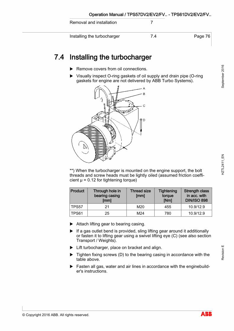
Operation Manual / TPS57DV2/EV2/FV.. - TPS61DV2/EV2/FV.. Removal and installation 7
Installing the turbocharger 7.4 Page 76
© Copyright 2016 ABB. All rights reserved.
Sept
embe
r 201
6 H
ZTL2
411_
EN
Rev
isio
n E
Installing the turbocharger 7.4
Remove covers from oil connections. Visually inspect O-ring gaskets of oil supply and drain pipe (O-ring
gaskets for engine are not delivered by ABB Turbo Systems).
**) When the turbocharger is mounted on the engine support, the bolt threads and screw heads must be lightly oiled (assumed friction coeffi-cient µ = 0.12 for tightening torque)
Product Through hole in bearing casing
[mm]
Thread size [mm]
Tightening torque [Nm]
Strength class in acc. with
DIN/ISO 898 TPS57 21 M20 455 10.9/12.9 TPS61 25 M24 780 10.9/12.9
Attach lifting gear to bearing casing. If a gas outlet bend is provided, sling lifting gear around it additionally
or fasten it to lifting gear using a swivel lifting eye (C) (see also section Transport / Weights).
Lift turbocharger, place on bracket and align. Tighten fixing screws (D) to the bearing casing in accordance with the
table above. Fasten all gas, water and air lines in accordance with the enginebuild-
er's instructions.
7.4

Operation Manual / TPS57DV2/EV2/FV.. - TPS61DV2/EV2/FV.. Removal and installation 7
Installing the turbocharger 7.4 Page 77
© Copyright 2016 ABB. All rights reserved.
Sept
embe
r 201
6 H
ZTL2
411_
EN
Rev
isio
n E
If present:
Fit speed sensor and plug in cable connector. Adapt and fit bearing casing insulation (A). Adapt and fit sheet metal (B) of bearing casing insulation.
Version with water-cooled bearing casing:
Remove the screw plugs from the water connections and fit the water pipes in accordance with the enginebuilder's instructions.
Place operating lever on marked fitting position and fit on VTG drive.

Operation Manual / TPS57DV2/EV2/FV.. - TPS61DV2/EV2/FV.. Disassembly and assembly 8
Introduction 8.1 Page 79
© Copyright 2016 ABB. All rights reserved.
Sept
embe
r 201
6 H
ZTL2
411_
EN
Rev
isio
n E
Disassembly and assembly
Introduction 8.1
Precondition for the work described below is a turbocharger removed from the engine (refer to the chapter entitled Removal and Installation).
CAUTION
Further work Only the work described in this Operation Manual may be carried out. Incorrectly performed disassembly and assembly of the cartridge group can lead to serious machine damage. ABB Turbo Systems recommends having further work carried out on-
ly by trained personnel from an ABB Turbocharging Service Station.
NOTICE
Marking casing positions for assembly ABB Turbo Systems recommends that the casing positions are marked before disassembling the turbocharger.
Identifying assembly devices
Not all assembly devices are marked with a part number. They can be identified using the tool list. This list is enclosed in the toolbox.
WARNING
Maintaining assembly devices Assembly devices must be checked for damage before and after use. Visually check for corrosion, cracks, deformation and wear. Don't use damaged assembly devices, but replace them.
8 8.1

Operation Manual / TPS57DV2/EV2/FV.. - TPS61DV2/EV2/FV.. Disassembly and assembly 8
Introduction 8.1 Page 80
© Copyright 2016 ABB. All rights reserved.
Sept
embe
r 201
6 H
ZTL2
411_
EN
Rev
isio
n E
Customer spare parts set
Before beginning work, ensure that the required customer spare parts sets are available.
See chapter Spare parts.
Oil orifice
When disassembling the turbocharger, a fitted oil orifice must not be removed.
Tightening torques for turbocharger components
The specified tightening torques of screw connections for turbocharger components must be observed. (See section Table of tightening torques.)
Tightening torques for assembly devices of ABB Turbo Systems
If nothing else is described, the screws and nuts of the assembly devices must be tightened down firmly.
WARNING
Suspended loads Loads not suspended in compliance with regulations may lead to per-sonal injury or accidents with fatal consequences. Attach turbochargers, assemblies or individual components only to
lifting gear which is in technically perfect condition and has sufficient load capacity.
Make sure the load is suspended properly on the crane hook. Do not let anyone stand beneath a suspended load.
Wear safety gloves to protect against mechanical hazards.
Wear safety helmet.
Definition of terms
Suspension point Defined load carrying point on a component or an assembly (blind hole thread, eye, lug).
Assembly device Devices mounted on the turbocharger to create a suspension point. Assembly devices are calculated and designed especially for the de-
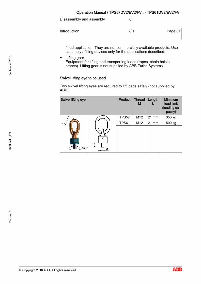
Operation Manual / TPS57DV2/EV2/FV.. - TPS61DV2/EV2/FV.. Disassembly and assembly 8
Introduction 8.1 Page 81
© Copyright 2016 ABB. All rights reserved.
Sept
embe
r 201
6 H
ZTL2
411_
EN
Rev
isio
n E
fined application. They are not commercially available products. Use assembly / fitting devices only for the applications described.
Lifting gear Equipment for lifting and transporting loads (ropes, chain hoists, cranes). Lifting gear is not supplied by ABB Turbo Systems.
Swivel lifting eye to be used
Two swivel lifting eyes are required to lift loads safely (not supplied by ABB).
Swivel lifting eye Product Thread M
Length L
Minimum load limit
(loading ca-pacity)
TPS57 M12 21 mm 350 kg TPS61 M12 21 mm 500 kg
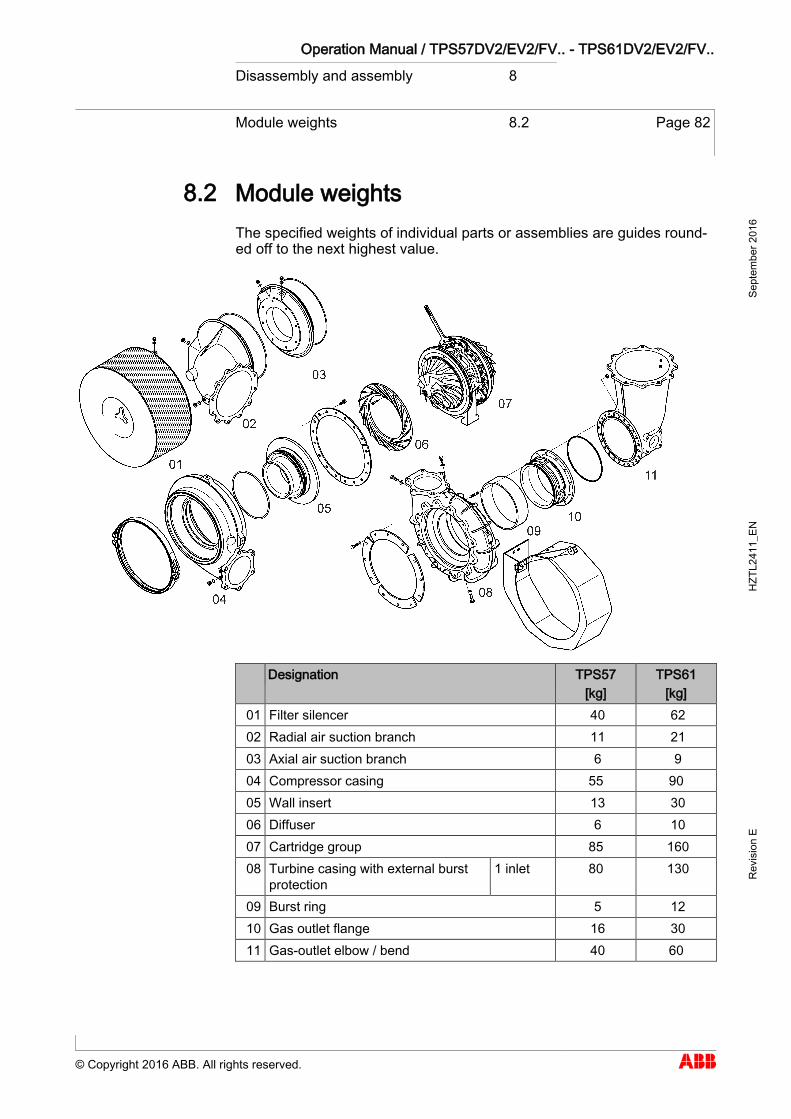
Operation Manual / TPS57DV2/EV2/FV.. - TPS61DV2/EV2/FV.. Disassembly and assembly 8
Module weights 8.2 Page 82
© Copyright 2016 ABB. All rights reserved.
Sept
embe
r 201
6 H
ZTL2
411_
EN
Rev
isio
n E
Module weights 8.2
The specified weights of individual parts or assemblies are guides round-ed off to the next highest value.
Designation TPS57 [kg]
TPS61 [kg]
01 Filter silencer 40 62 02 Radial air suction branch 11 21 03 Axial air suction branch 6 9 04 Compressor casing 55 90 05 Wall insert 13 30 06 Diffuser 6 10 07 Cartridge group 85 160 08 Turbine casing with external burst
protection 1 inlet 80 130
09 Burst ring 5 12 10 Gas outlet flange 16 30 11 Gas-outlet elbow / bend 40 60
8.2
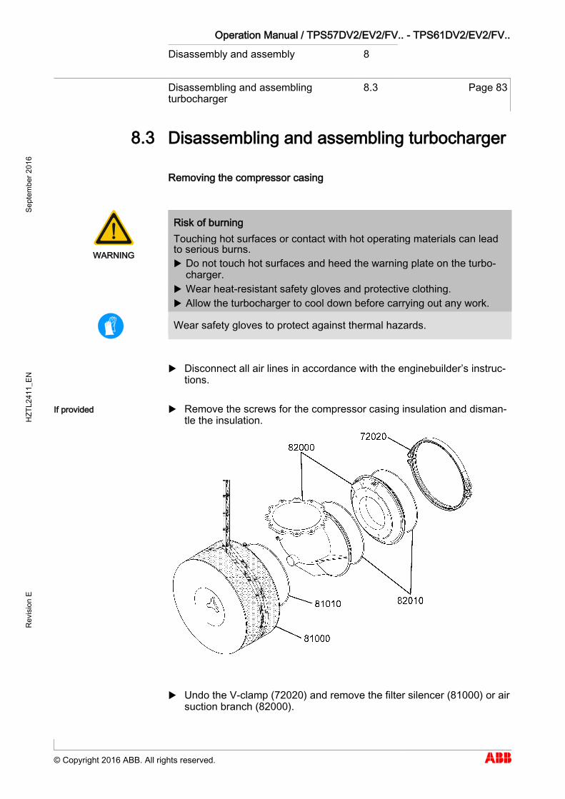
Operation Manual / TPS57DV2/EV2/FV.. - TPS61DV2/EV2/FV.. Disassembly and assembly 8
Disassembling and assembling turbocharger
8.3 Page 83
© Copyright 2016 ABB. All rights reserved.
Sept
embe
r 201
6 H
ZTL2
411_
EN
Rev
isio
n E
Disassembling and assembling turbocharger 8.3
Removing the compressor casing
WARNING
Risk of burning Touching hot surfaces or contact with hot operating materials can lead to serious burns. Do not touch hot surfaces and heed the warning plate on the turbo-
charger. Wear heat-resistant safety gloves and protective clothing. Allow the turbocharger to cool down before carrying out any work.
Wear safety gloves to protect against thermal hazards.
Disconnect all air lines in accordance with the enginebuilder’s instruc-tions.
Remove the screws for the compressor casing insulation and disman-tle the insulation.
Undo the V-clamp (72020) and remove the filter silencer (81000) or air suction branch (82000).
8.3
If provided
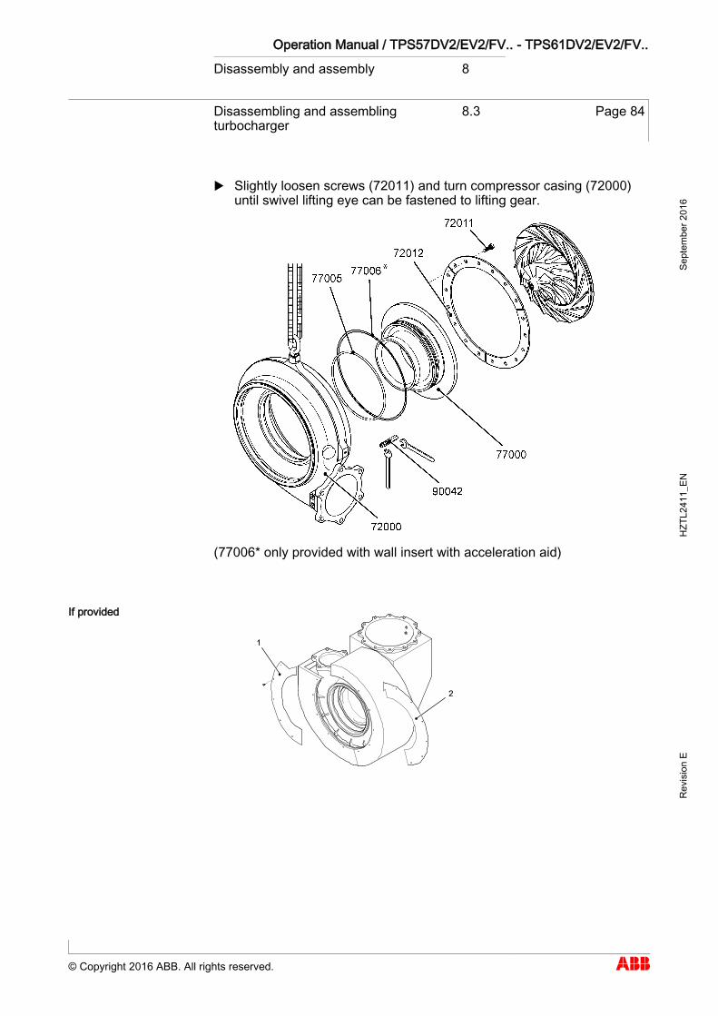
Operation Manual / TPS57DV2/EV2/FV.. - TPS61DV2/EV2/FV.. Disassembly and assembly 8
Disassembling and assembling turbocharger
8.3 Page 84
© Copyright 2016 ABB. All rights reserved.
Sept
embe
r 201
6 H
ZTL2
411_
EN
Rev
isio
n E
Slightly loosen screws (72011) and turn compressor casing (72000) until swivel lifting eye can be fastened to lifting gear.
(77006* only provided with wall insert with acceleration aid)
If provided
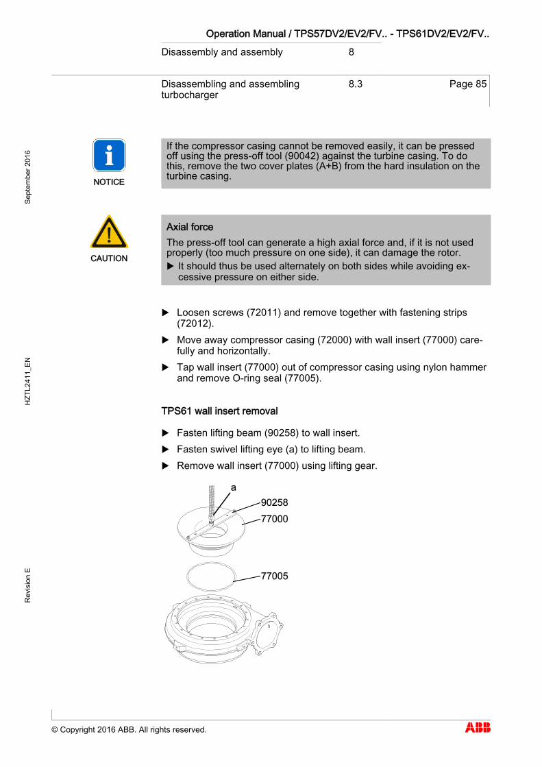
Operation Manual / TPS57DV2/EV2/FV.. - TPS61DV2/EV2/FV.. Disassembly and assembly 8
Disassembling and assembling turbocharger
8.3 Page 85
© Copyright 2016 ABB. All rights reserved.
Sept
embe
r 201
6 H
ZTL2
411_
EN
Rev
isio
n E
NOTICE
If the compressor casing cannot be removed easily, it can be pressed off using the press-off tool (90042) against the turbine casing. To do this, remove the two cover plates (A+B) from the hard insulation on the turbine casing.
CAUTION
Axial force The press-off tool can generate a high axial force and, if it is not used properly (too much pressure on one side), it can damage the rotor. It should thus be used alternately on both sides while avoiding ex-
cessive pressure on either side.
Loosen screws (72011) and remove together with fastening strips (72012).
Move away compressor casing (72000) with wall insert (77000) care-fully and horizontally.
Tap wall insert (77000) out of compressor casing using nylon hammer and remove O-ring seal (77005).
TPS61 wall insert removal
Fasten lifting beam (90258) to wall insert. Fasten swivel lifting eye (a) to lifting beam. Remove wall insert (77000) using lifting gear.
Operation Manual / TPS57DV2/EV2/FV.. - TPS61DV2/EV2/FV.. Disassembly and assembly 8
Disassembling and assembling turbocharger
8.3 Page 86
© Copyright 2016 ABB. All rights reserved.
Sept
embe
r 201
6 H
ZTL2
411_
EN
Rev
isio
n E
Installing compressor casing
Refit wall insert (77000) and O-ring (77005) in reverse order.
NOTICE
O-rings Used O-rings must always be replaced with new ones. O-rings are only available as a set (see chapter Spare parts).
Install compressor casing in reverse order. Thoroughly clean fastening strips (72012) before fitting them.
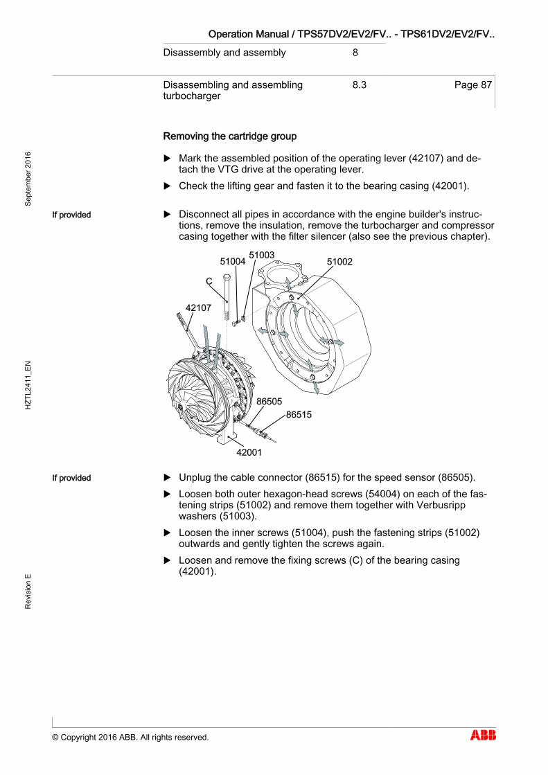
Operation Manual / TPS57DV2/EV2/FV.. - TPS61DV2/EV2/FV.. Disassembly and assembly 8
Disassembling and assembling turbocharger
8.3 Page 87
© Copyright 2016 ABB. All rights reserved.
Sept
embe
r 201
6 H
ZTL2
411_
EN
Rev
isio
n E
Removing the cartridge group
Mark the assembled position of the operating lever (42107) and de-tach the VTG drive at the operating lever.
Check the lifting gear and fasten it to the bearing casing (42001).
Disconnect all pipes in accordance with the engine builder's instruc-tions, remove the insulation, remove the turbocharger and compressor casing together with the filter silencer (also see the previous chapter).
Unplug the cable connector (86515) for the speed sensor (86505). Loosen both outer hexagon-head screws (54004) on each of the fas-
tening strips (51002) and remove them together with Verbusripp washers (51003).
Loosen the inner screws (51004), push the fastening strips (51002) outwards and gently tighten the screws again.
Loosen and remove the fixing screws (C) of the bearing casing (42001).
If provided
If provided
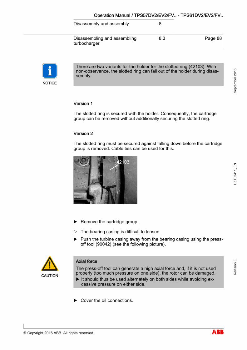
Operation Manual / TPS57DV2/EV2/FV.. - TPS61DV2/EV2/FV.. Disassembly and assembly 8
Disassembling and assembling turbocharger
8.3 Page 88
© Copyright 2016 ABB. All rights reserved.
Sept
embe
r 201
6 H
ZTL2
411_
EN
Rev
isio
n E
NOTICE
There are two variants for the holder for the slotted ring (42103). With non-observance, the slotted ring can fall out of the holder during disas-sembly.
Version 1
The slotted ring is secured with the holder. Consequently, the cartridge group can be removed without additionally securing the slotted ring.
Version 2
The slotted ring must be secured against falling down before the cartridge group is removed. Cable ties can be used for this.
Remove the cartridge group.
The bearing casing is difficult to loosen. Push the turbine casing away from the bearing casing using the press-
off tool (90042) (see the following picture).
CAUTION
Axial force The press-off tool can generate a high axial force and, if it is not used properly (too much pressure on one side), the rotor can be damaged. It should thus be used alternately on both sides while avoiding ex-
cessive pressure on either side.
Cover the oil connections.
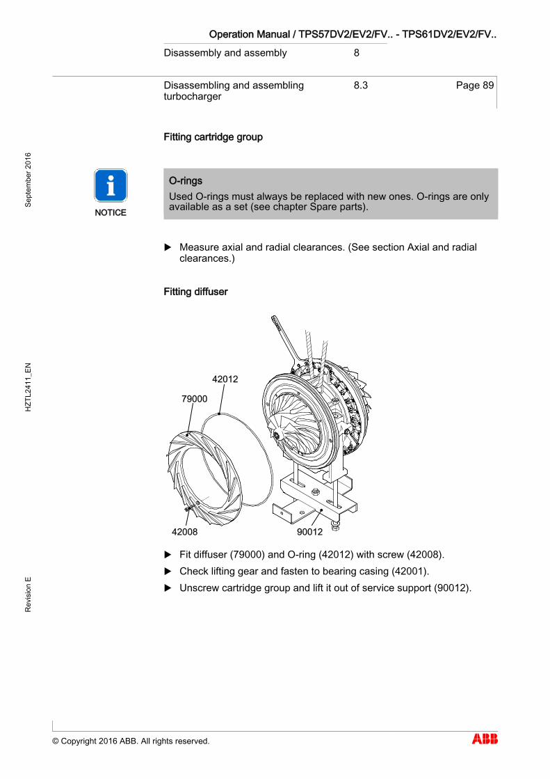
Operation Manual / TPS57DV2/EV2/FV.. - TPS61DV2/EV2/FV.. Disassembly and assembly 8
Disassembling and assembling turbocharger
8.3 Page 89
© Copyright 2016 ABB. All rights reserved.
Sept
embe
r 201
6 H
ZTL2
411_
EN
Rev
isio
n E
Fitting cartridge group
NOTICE
O-rings Used O-rings must always be replaced with new ones. O-rings are only available as a set (see chapter Spare parts).
Measure axial and radial clearances. (See section Axial and radial clearances.)
Fitting diffuser
Fit diffuser (79000) and O-ring (42012) with screw (42008). Check lifting gear and fasten to bearing casing (42001). Unscrew cartridge group and lift it out of service support (90012).
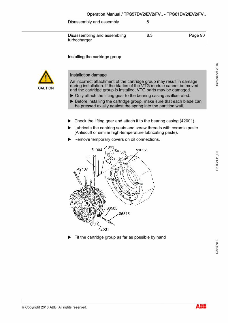
Operation Manual / TPS57DV2/EV2/FV.. - TPS61DV2/EV2/FV.. Disassembly and assembly 8
Disassembling and assembling turbocharger
8.3 Page 90
© Copyright 2016 ABB. All rights reserved.
Sept
embe
r 201
6 H
ZTL2
411_
EN
Rev
isio
n E
Installing the cartridge group
CAUTION
Installation damage An incorrect attachment of the cartridge group may result in damage during installation. If the blades of the VTG module cannot be moved and the cartridge group is installed, VTG parts may be damaged. Only attach the lifting gear to the bearing casing as illustrated. Before installing the cartridge group, make sure that each blade can
be pressed axially against the spring into the partition wall.
Check the lifting gear and attach it to the bearing casing (42001). Lubricate the centring seats and screw threads with ceramic paste
(Antiscuff or similar high-temperature lubricating paste). Remove temporary covers on oil connections.
Fit the cartridge group as far as possible by hand
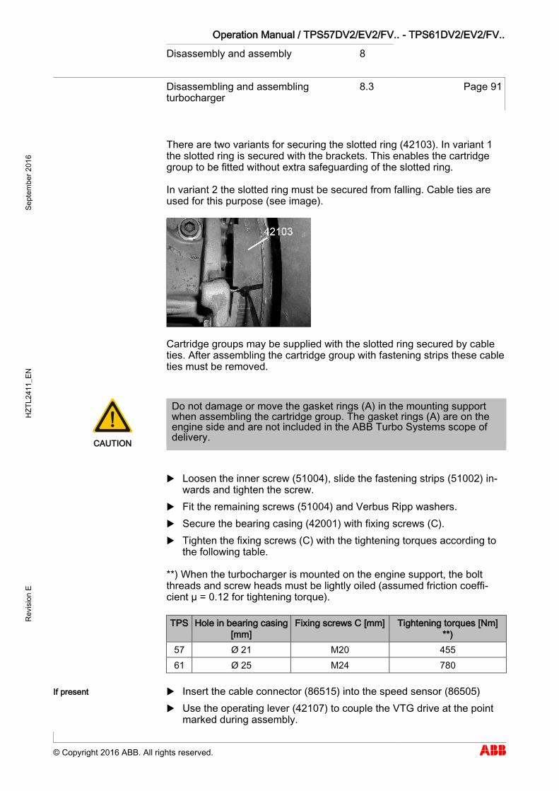
Operation Manual / TPS57DV2/EV2/FV.. - TPS61DV2/EV2/FV.. Disassembly and assembly 8
Disassembling and assembling turbocharger
8.3 Page 91
© Copyright 2016 ABB. All rights reserved.
Sept
embe
r 201
6 H
ZTL2
411_
EN
Rev
isio
n E
There are two variants for securing the slotted ring (42103). In variant 1 the slotted ring is secured with the brackets. This enables the cartridge group to be fitted without extra safeguarding of the slotted ring.
In variant 2 the slotted ring must be secured from falling. Cable ties are used for this purpose (see image).
Cartridge groups may be supplied with the slotted ring secured by cable ties. After assembling the cartridge group with fastening strips these cable ties must be removed.
CAUTION
Do not damage or move the gasket rings (A) in the mounting support when assembling the cartridge group. The gasket rings (A) are on the engine side and are not included in the ABB Turbo Systems scope of delivery.
Loosen the inner screw (51004), slide the fastening strips (51002) in-wards and tighten the screw.
Fit the remaining screws (51004) and Verbus Ripp washers. Secure the bearing casing (42001) with fixing screws (C). Tighten the fixing screws (C) with the tightening torques according to
the following table.
**) When the turbocharger is mounted on the engine support, the bolt threads and screw heads must be lightly oiled (assumed friction coeffi-cient µ = 0.12 for tightening torque).
TPS Hole in bearing casing [mm]
Fixing screws C [mm] Tightening torques [Nm] **)
57 Ø 21 M20 455 61 Ø 25 M24 780
Insert the cable connector (86515) into the speed sensor (86505) Use the operating lever (42107) to couple the VTG drive at the point
marked during assembly.
If present
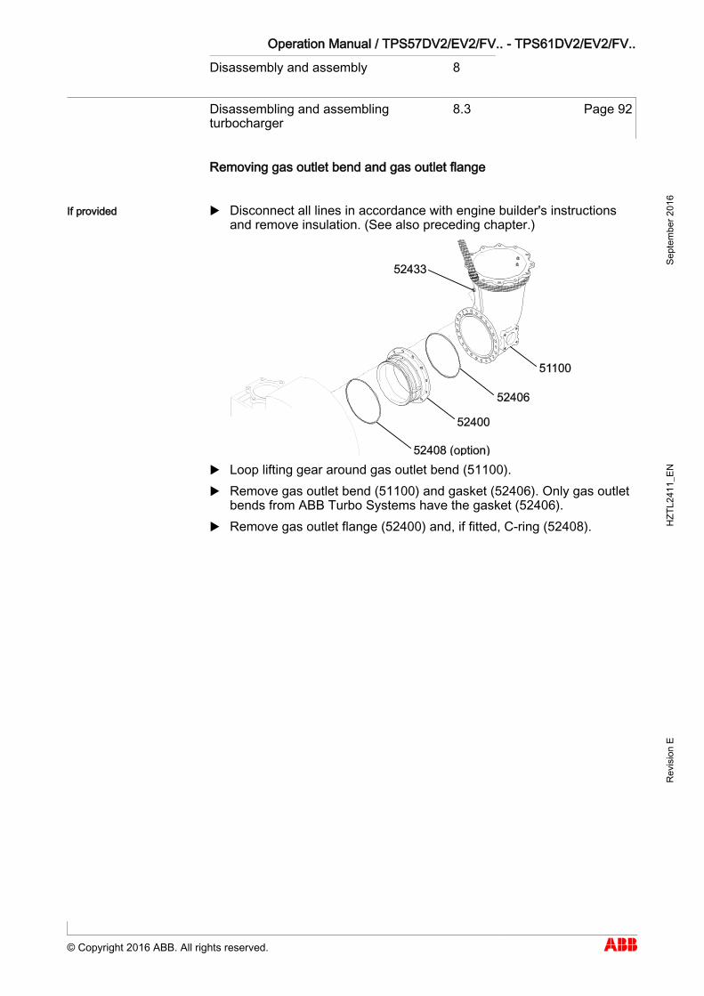
Operation Manual / TPS57DV2/EV2/FV.. - TPS61DV2/EV2/FV.. Disassembly and assembly 8
Disassembling and assembling turbocharger
8.3 Page 92
© Copyright 2016 ABB. All rights reserved.
Sept
embe
r 201
6 H
ZTL2
411_
EN
Rev
isio
n E
Removing gas outlet bend and gas outlet flange
Disconnect all lines in accordance with engine builder's instructions and remove insulation. (See also preceding chapter.)
Loop lifting gear around gas outlet bend (51100). Remove gas outlet bend (51100) and gasket (52406). Only gas outlet
bends from ABB Turbo Systems have the gasket (52406). Remove gas outlet flange (52400) and, if fitted, C-ring (52408).
If provided
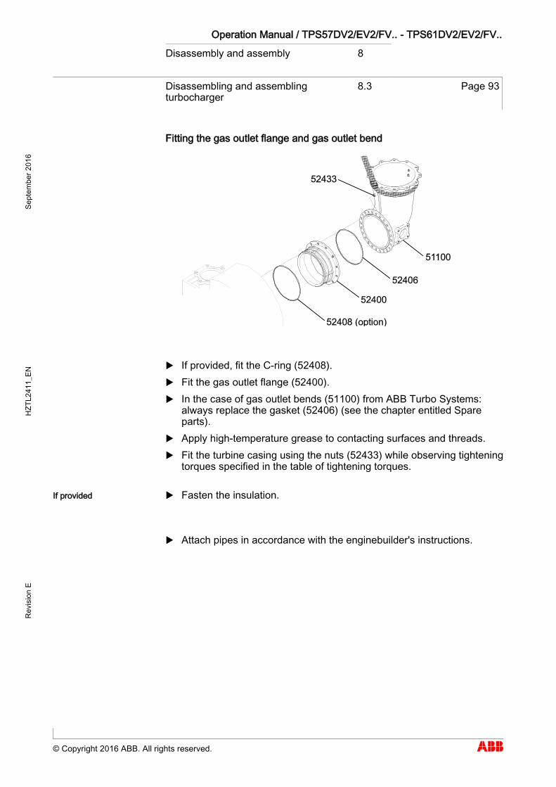
Operation Manual / TPS57DV2/EV2/FV.. - TPS61DV2/EV2/FV.. Disassembly and assembly 8
Disassembling and assembling turbocharger
8.3 Page 93
© Copyright 2016 ABB. All rights reserved.
Sept
embe
r 201
6 H
ZTL2
411_
EN
Rev
isio
n E
Fitting the gas outlet flange and gas outlet bend
If provided, fit the C-ring (52408). Fit the gas outlet flange (52400). In the case of gas outlet bends (51100) from ABB Turbo Systems:
always replace the gasket (52406) (see the chapter entitled Spare parts).
Apply high-temperature grease to contacting surfaces and threads. Fit the turbine casing using the nuts (52433) while observing tightening
torques specified in the table of tightening torques.
Fasten the insulation.
Attach pipes in accordance with the enginebuilder's instructions.
If provided
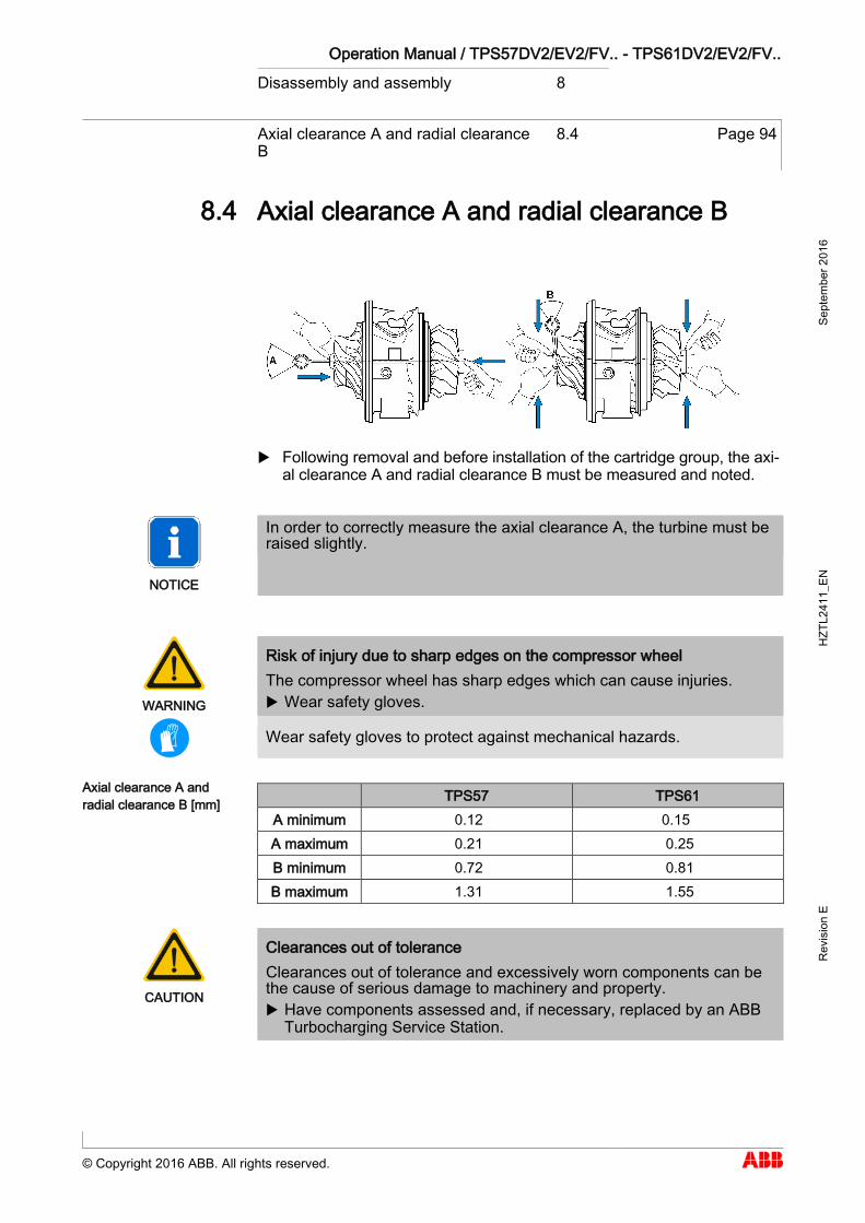
Operation Manual / TPS57DV2/EV2/FV.. - TPS61DV2/EV2/FV.. Disassembly and assembly 8
Axial clearance A and radial clearance B
8.4 Page 94
© Copyright 2016 ABB. All rights reserved.
Sept
embe
r 201
6 H
ZTL2
411_
EN
Rev
isio
n E
Axial clearance A and radial clearance B 8.4
Following removal and before installation of the cartridge group, the axi-al clearance A and radial clearance B must be measured and noted.
NOTICE
In order to correctly measure the axial clearance A, the turbine must be raised slightly.
WARNING
Risk of injury due to sharp edges on the compressor wheel The compressor wheel has sharp edges which can cause injuries. Wear safety gloves.
Wear safety gloves to protect against mechanical hazards.
TPS57 TPS61 A minimum 0.12 0.15 A maximum 0.21 0.25 B minimum 0.72 0.81 B maximum 1.31 1.55
CAUTION
Clearances out of tolerance Clearances out of tolerance and excessively worn components can be the cause of serious damage to machinery and property. Have components assessed and, if necessary, replaced by an ABB
Turbocharging Service Station.
8.4
Axial clearance A and radial clearance B [mm]
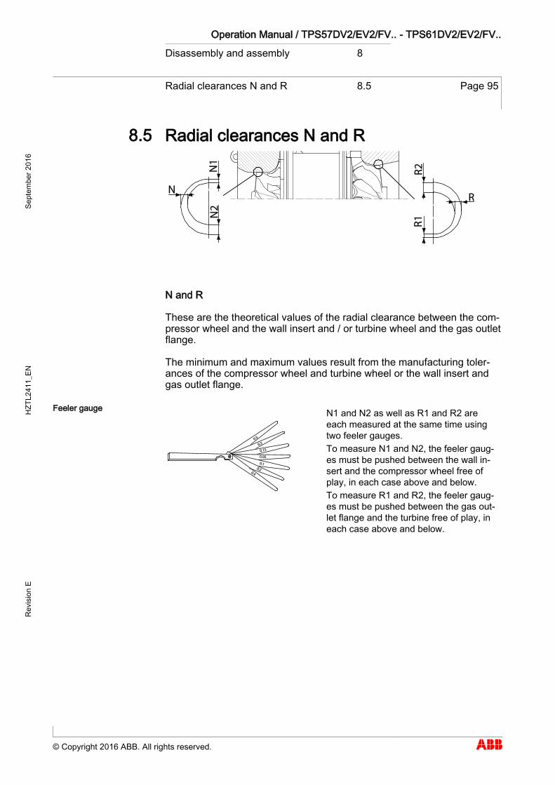
Operation Manual / TPS57DV2/EV2/FV.. - TPS61DV2/EV2/FV.. Disassembly and assembly 8
Radial clearances N and R 8.5 Page 95
© Copyright 2016 ABB. All rights reserved.
Sept
embe
r 201
6 H
ZTL2
411_
EN
Rev
isio
n E
Radial clearances N and R 8.5
N and R
These are the theoretical values of the radial clearance between the com-pressor wheel and the wall insert and / or turbine wheel and the gas outlet flange.
The minimum and maximum values result from the manufacturing toler-ances of the compressor wheel and turbine wheel or the wall insert and gas outlet flange.
N1 and N2 as well as R1 and R2 are each measured at the same time using two feeler gauges. To measure N1 and N2, the feeler gaug-es must be pushed between the wall in-sert and the compressor wheel free of play, in each case above and below. To measure R1 and R2, the feeler gaug-es must be pushed between the gas out-let flange and the turbine free of play, in each case above and below.
8.5
Feeler gauge
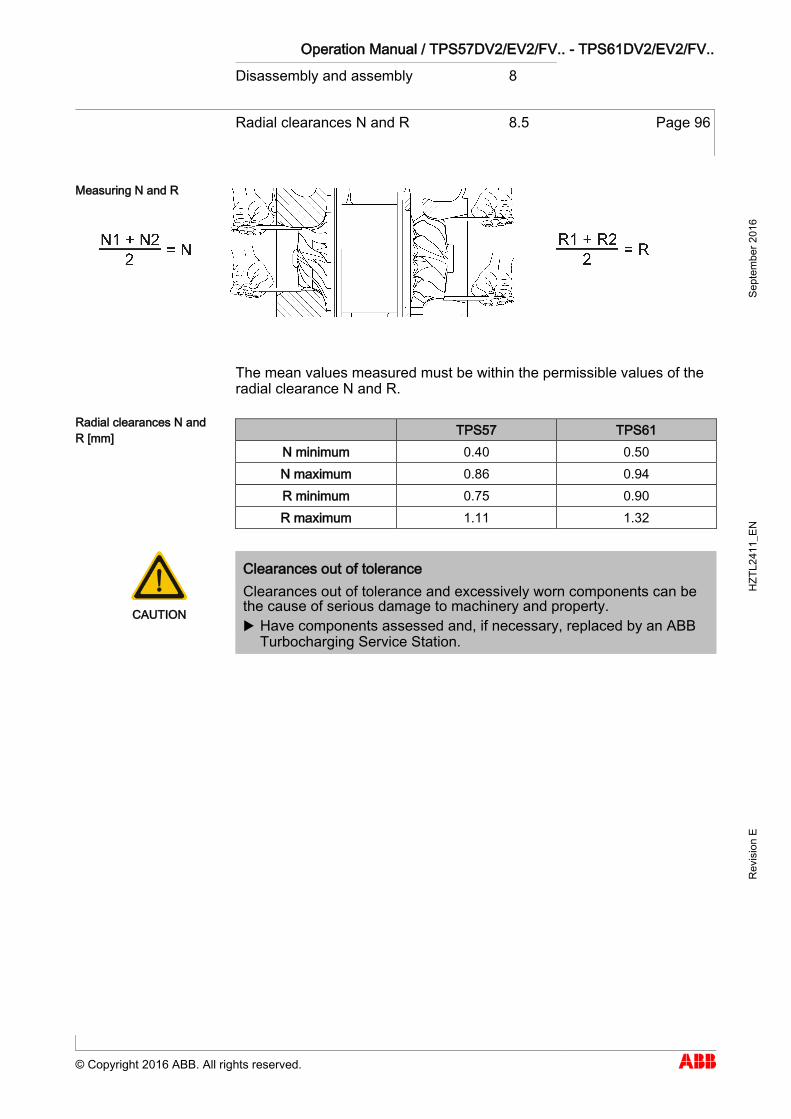
Operation Manual / TPS57DV2/EV2/FV.. - TPS61DV2/EV2/FV.. Disassembly and assembly 8
Radial clearances N and R 8.5 Page 96
© Copyright 2016 ABB. All rights reserved.
Sept
embe
r 201
6 H
ZTL2
411_
EN
Rev
isio
n E
The mean values measured must be within the permissible values of the radial clearance N and R.
TPS57 TPS61 N minimum 0.40 0.50 N maximum 0.86 0.94 R minimum 0.75 0.90 R maximum 1.11 1.32
CAUTION
Clearances out of tolerance Clearances out of tolerance and excessively worn components can be the cause of serious damage to machinery and property. Have components assessed and, if necessary, replaced by an ABB
Turbocharging Service Station.
Measuring N and R
Radial clearances N and R [mm]
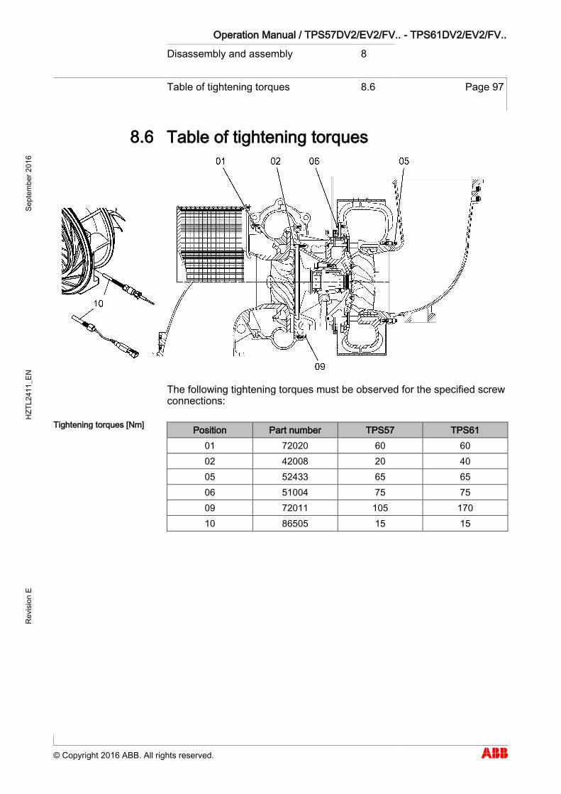
Operation Manual / TPS57DV2/EV2/FV.. - TPS61DV2/EV2/FV.. Disassembly and assembly 8
Table of tightening torques 8.6 Page 97
© Copyright 2016 ABB. All rights reserved.
Sept
embe
r 201
6 H
ZTL2
411_
EN
Rev
isio
n E
Table of tightening torques 8.6
The following tightening torques must be observed for the specified screw connections:
Position Part number TPS57 TPS61 01 72020 60 60 02 42008 20 40 05 52433 65 65 06 51004 75 75 09 72011 105 170 10 86505 15 15
8.6
Tightening torques [Nm]

Operation Manual / TPS57DV2/EV2/FV.. - TPS61DV2/EV2/FV.. Taking out of operation 9
Shut down turbocharger 9.1 Page 99
© Copyright 2016 ABB. All rights reserved.
Sept
embe
r 201
6 H
ZTL2
411_
EN
Rev
isio
n E
Taking out of operation
Shut down turbocharger 9.1
If the turbocharger is damaged and the engine can be shut down for only a short time for emergency repairs, proceed as follows:
Fit the cover plate.
CAUTION
Always precisely obey the engine builder's instructions in case of en-gine operation with a blocked/throttled turbocharger!
Dismantling the turbocharger
Dismantling the turbocharger (see the chapter entitled Dismantling and fitting the turbocharger)
9 9.1
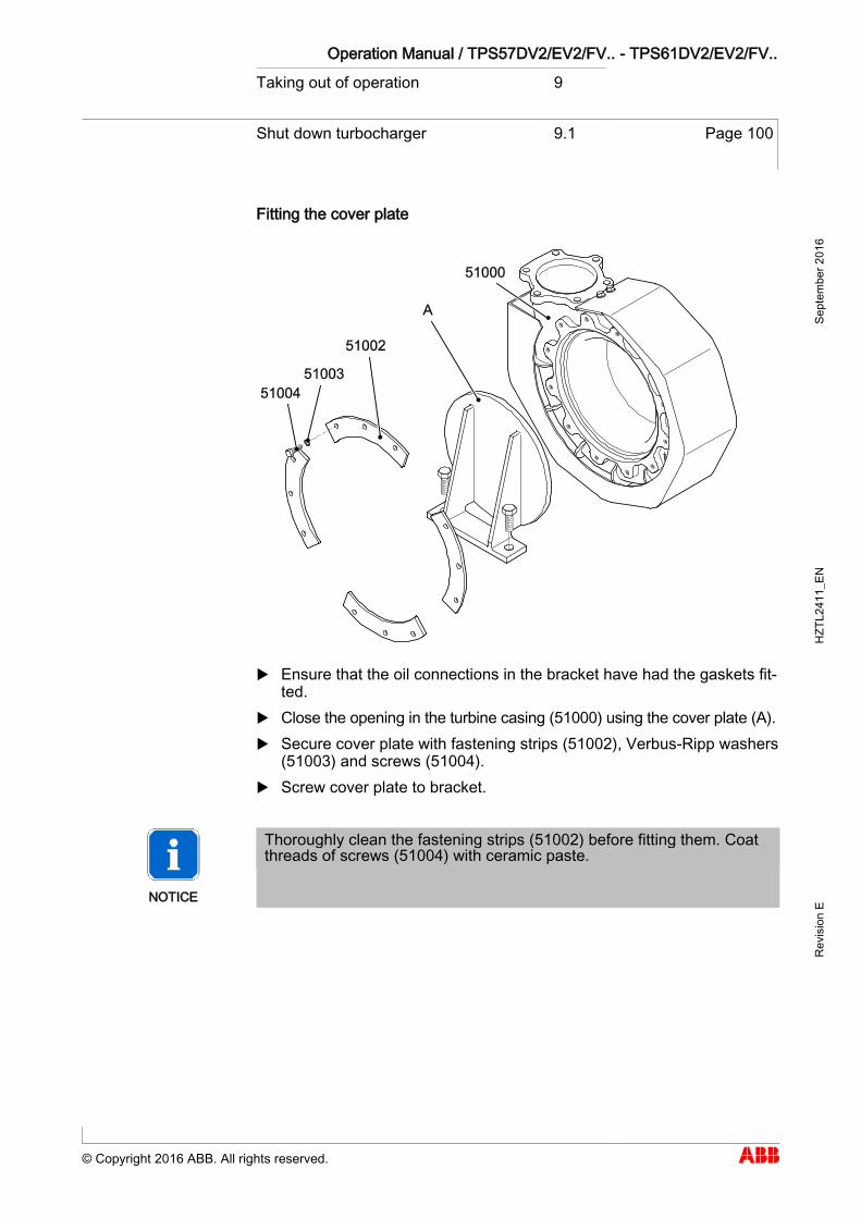
Operation Manual / TPS57DV2/EV2/FV.. - TPS61DV2/EV2/FV.. Taking out of operation 9
Shut down turbocharger 9.1 Page 100
© Copyright 2016 ABB. All rights reserved.
Sept
embe
r 201
6 H
ZTL2
411_
EN
Rev
isio
n E
Fitting the cover plate
Ensure that the oil connections in the bracket have had the gaskets fit-ted.
Close the opening in the turbine casing (51000) using the cover plate (A). Secure cover plate with fastening strips (51002), Verbus-Ripp washers
(51003) and screws (51004). Screw cover plate to bracket.
NOTICE
Thoroughly clean the fastening strips (51002) before fitting them. Coat threads of screws (51004) with ceramic paste.
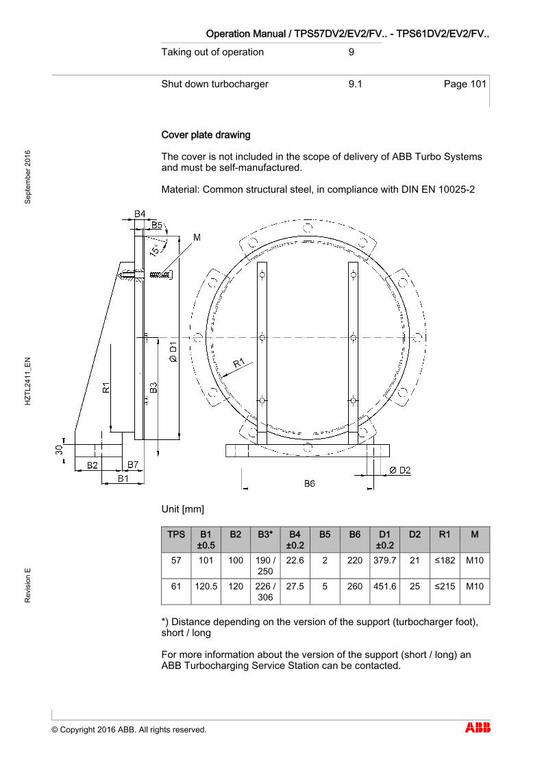
Operation Manual / TPS57DV2/EV2/FV.. - TPS61DV2/EV2/FV.. Taking out of operation 9
Shut down turbocharger 9.1 Page 101
© Copyright 2016 ABB. All rights reserved.
Sept
embe
r 201
6 H
ZTL2
411_
EN
Rev
isio
n E
Cover plate drawing
The cover is not included in the scope of delivery of ABB Turbo Systems and must be self-manufactured.
Material: Common structural steel, in compliance with DIN EN 10025-2
Unit [mm]
TPS B1 ±0.5
B2 B3* B4 ±0.2
B5 B6 D1 ±0.2
D2 R1 M
57 101 100 190 / 250
22.6 2 220 379.7 21 ≤182 M10
61 120.5 120 226 / 306
27.5 5 260 451.6 25 ≤215 M10
*) Distance depending on the version of the support (turbocharger foot), short / long
For more information about the version of the support (short / long) an ABB Turbocharging Service Station can be contacted.

Operation Manual / TPS57DV2/EV2/FV.. - TPS61DV2/EV2/FV.. Mothballing the turbocharger 10
Taking the engine out of operation for up to 12 months
10.1 Page 103
© Copyright 2016 ABB. All rights reserved.
Sept
embe
r 201
6 H
ZTL2
411_
EN
Rev
isio
n E
Mothballing the turbocharger
Taking the engine out of operation for up to 12 months
10.1
Condition of engine lubricating oil
The turbocharger normally remains mounted on the engine. Mothballing a turbocharger depends on the condition of the lubricating oil:
If the total acid number (TAN) is lower than 2 mg KOH/g, no measures have to be taken.
If the engine lubricating oil is replaced by preserving oil before taking the engine out of operation and this is circulated by the pre-lubrication pump, no measures have to be taken. Any remaining old engine oil will therefore be flushed away and the bearing sections largely protected against corrosion.
Mothballing measures
WARNING
Handling operating materials and supplies Swallowing or inhaling vapours of operating materials and supplies or contact with them may be harmful to health. Do not breathe in these substances and avoid contact with the skin. Ensure proper ventilation. Observe the information in the material safety data sheet for the op-
erating materials and supplies. Wear personal protective equipment (PPE) according to the material
safety data sheet. Comply with local legislation.
Wear safety goggles.
Wear safety gloves to protect against chemical hazards.
Wear a respiratory mask to protect against gases.
10 10.1
Operation Manual / TPS57DV2/EV2/FV.. - TPS61DV2/EV2/FV.. Mothballing the turbocharger 10
Taking the engine out of operation for up to 12 months
10.1 Page 104
© Copyright 2016 ABB. All rights reserved.
Sept
embe
r 201
6 H
ZTL2
411_
EN
Rev
isio
n E
If the total acid number (TAN) is greater than 2 mg KOH/g, the following mothballing measures are necessary after taking an engine out of opera-tion:
Dismantle the turbocharger. The rotor and the bearing parts must be removed by an official ABB
Turbocharging service station and refitted afterwards. Clean all parts. Machined, bright surfaces of steel and cast parts must be oiled with
anticorrosive oil. Reassemble complete turbocharger.
Rotor turning in stack draught
If the rotor turns as a result of the stack draught:
Install blind flange between compressor casing outlet flange and charge air duct.
Operation Manual / TPS57DV2/EV2/FV.. - TPS61DV2/EV2/FV.. Mothballing the turbocharger 10
Taking the engine out of operation for more than 12 months
10.2 Page 105
© Copyright 2016 ABB. All rights reserved.
Sept
embe
r 201
6 H
ZTL2
411_
EN
Rev
isio
n E
Taking the engine out of operation for more than 12 months 10.2
If the engine is taken out of service, the following alternatives are possible with the turbocharger:
The turbocharger remains mounted on the engine. The turbocharger casing remains mounted on the engine, but the rotor
and the bearing parts are removed and stored separately by an ABB Turbocharging Service Station.
The turbocharger is removed completely, either as a whole or in indi-vidual parts.
See the section Taking out of operation for up to 12 months, under Moth-balling measures, for the measures always necessary when mothballing turbocharger parts.
If the turbocharger remains mounted on the engine, refer to the section Taking out of operation for up to 12 months, under Rotating the rotor in stack draught.
If the entire turbocharger is removed, or if the turbocharger is re-assembled from the individual components thereof:
Close all turbocharger openings using wooden covers and paraffin paper.
Suitable storage locations are only dry rooms where the relative humidity is between 40 … 70 % and no condensation can form.
Condition of the mothballed turbocharger
Check the mothballed turbocharger parts for corrosion once per an-num.
If there are signs of rust: Clean parts thoroughly and renew protection against corrosion.
10.2

Operation Manual / TPS57DV2/EV2/FV.. - TPS61DV2/EV2/FV.. Disposing of turbocharger components 11
Taking the engine out of operation for more than 12 months
10.2 Page 107
© Copyright 2016 ABB. All rights reserved.
Sept
embe
r 201
6 H
ZTL2
411_
EN
Rev
isio
n E
Disposing of turbocharger components
WARNING
Handling damaged thermal insulation Damaged thermal insulation can lead to dust exposure. The glass fibres can cause mechanical irritation of the eyes, skin, and respiratory tracts. Avoid the formation of dust. Vacuum up dust with a suitable vacuum cleaner. Wear a respiratory mask to protect against particles (P1 or P2 mask). Wear work gloves made of leather.
Wear safety goggles.
Wear a respiratory mask to protect against dusts.
Wear safety gloves to protect against mechanical hazards.
Disposal must be environmentally compatible, professional, and in com-pliance with locally applicable regulations.
The turbocharger consists largely of metal (cast iron materials, steel, nickel-steel alloys, aluminium and bearing brass).
Further components are: Non-metallic materials (filter components of felt and polyethylene), lubricants (engine oil), electronic parts (speed sensor and associated components), and thermal insulation.
Dispose of metals as scrap metal for recycling. Dispose of non-metallic materials as waste. Dispose of residues of lubricants as waste oil. Dispose of electronic components as electronic waste. Dispose of thermal insulation as hazardous waste.
11

Operation Manual / TPS57DV2/EV2/FV.. - TPS61DV2/EV2/FV.. Spare parts 12
Ordering spare parts 12.1 Page 109
© Copyright 2016 ABB. All rights reserved.
Sept
embe
r 201
6 H
ZTL2
411_
EN
Rev
isio
n E
Spare parts
Ordering spare parts 12.1
The following data must be specified when making inquiries or ordering spare parts:
Turbocharger type Serial number (HT……) Description and part number
Our service stations and agents take orders for spare parts.
Contact an ABB Turbocharger service station or an ABB agent if spe-cial versions / cases are not addressed in these general instructions.
CAUTION
Storage of spare parts All spare parts ordered with the turbocharger must be kept complete and ready for use. Parts showing signs of rust should be carefully cleaned and greased.
Dispose of replaced and unusable parts in a professional and envi-ronmentally compatible way.
12 12.1

Operation Manual / TPS57DV2/EV2/FV.. - TPS61DV2/EV2/FV.. Spare parts 12
Ordering spare parts 12.1 Page 110
© Copyright 2016 ABB. All rights reserved.
Sept
embe
r 201
6 H
ZTL2
411_
EN
Rev
isio
n E
Customer spare part set (97070)
NOTICE
The customer spare part set (97070) is required for the work described in this manual. The parts included in the customer spare part set are available only as a complete set.
Quantity Description Part number 1 Hexagon socket head screw 42008 1 O-ring 42012/ 81010/ 82010 1 O-ring 77005 1 Gasket 52406 * 2 Counter-sunk screw 72041
* This gasket can only be inserted when using a gas outlet casing from ABB Turbo Systems.
Operation Manual / TPS57DV2/EV2/FV.. - TPS61DV2/EV2/FV.. Spare parts 12
Ordering spare parts 12.1 Page 111
© Copyright 2016 ABB. All rights reserved.
Sept
embe
r 201
6 H
ZTL2
411_
EN
Rev
isio
n E
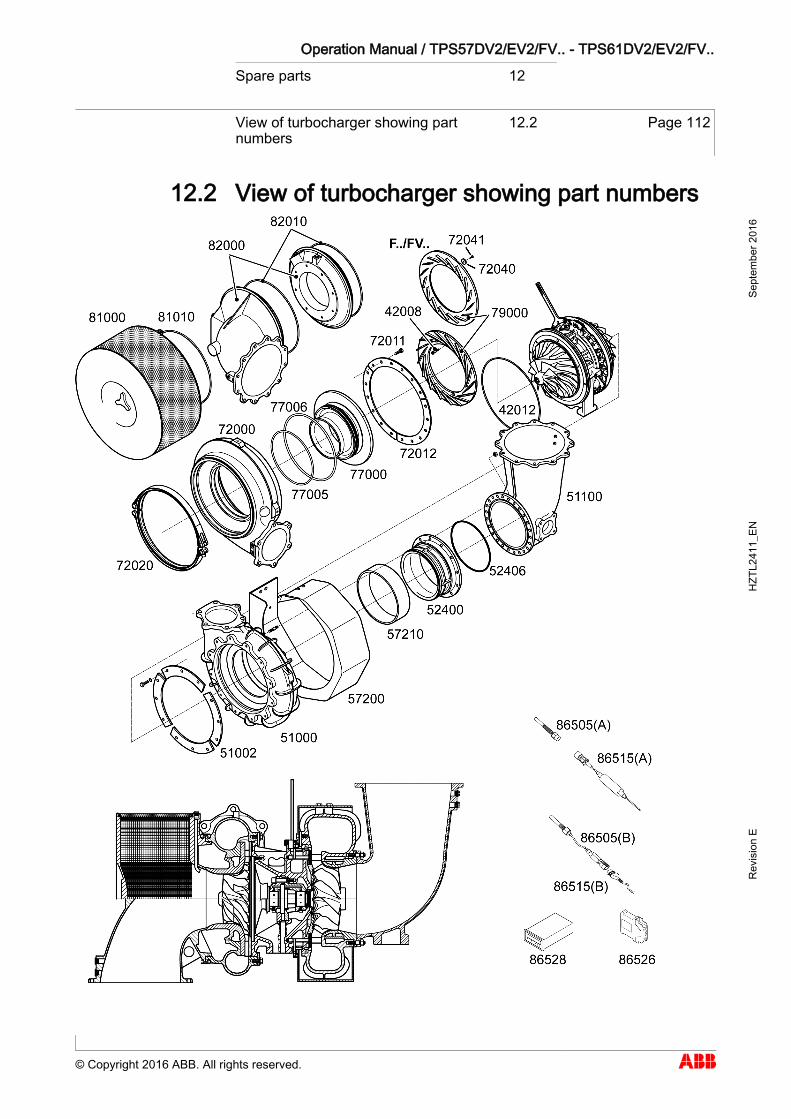
Operation Manual / TPS57DV2/EV2/FV.. - TPS61DV2/EV2/FV.. Spare parts 12
View of turbocharger showing part numbers
12.2 Page 112
© Copyright 2016 ABB. All rights reserved.
Sept
embe
r 201
6 H
ZTL2
411_
EN
Rev
isio
n E
View of turbocharger showing part numbers 12.2
12.2
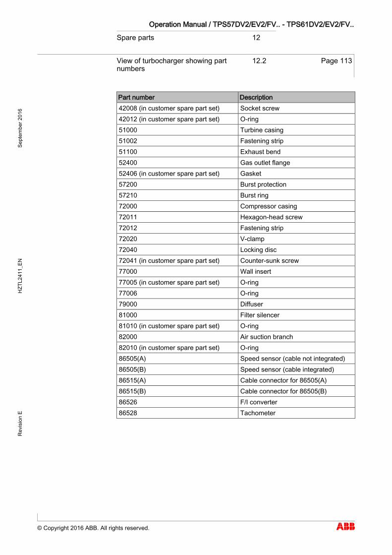
Operation Manual / TPS57DV2/EV2/FV.. - TPS61DV2/EV2/FV.. Spare parts 12
View of turbocharger showing part numbers
12.2 Page 113
© Copyright 2016 ABB. All rights reserved.
Sept
embe
r 201
6 H
ZTL2
411_
EN
Rev
isio
n E
Part number Description 42008 (in customer spare part set) Socket screw 42012 (in customer spare part set) O-ring 51000 Turbine casing 51002 Fastening strip 51100 Exhaust bend 52400 Gas outlet flange 52406 (in customer spare part set) Gasket 57200 Burst protection 57210 Burst ring 72000 Compressor casing 72011 Hexagon-head screw 72012 Fastening strip 72020 V-clamp 72040 Locking disc 72041 (in customer spare part set) Counter-sunk screw 77000 Wall insert 77005 (in customer spare part set) O-ring 77006 O-ring 79000 Diffuser 81000 Filter silencer 81010 (in customer spare part set) O-ring 82000 Air suction branch 82010 (in customer spare part set) O-ring 86505(A) Speed sensor (cable not integrated) 86505(B) Speed sensor (cable integrated) 86515(A) Cable connector for 86505(A) 86515(B) Cable connector for 86505(B) 86526 F/I converter 86528 Tachometer
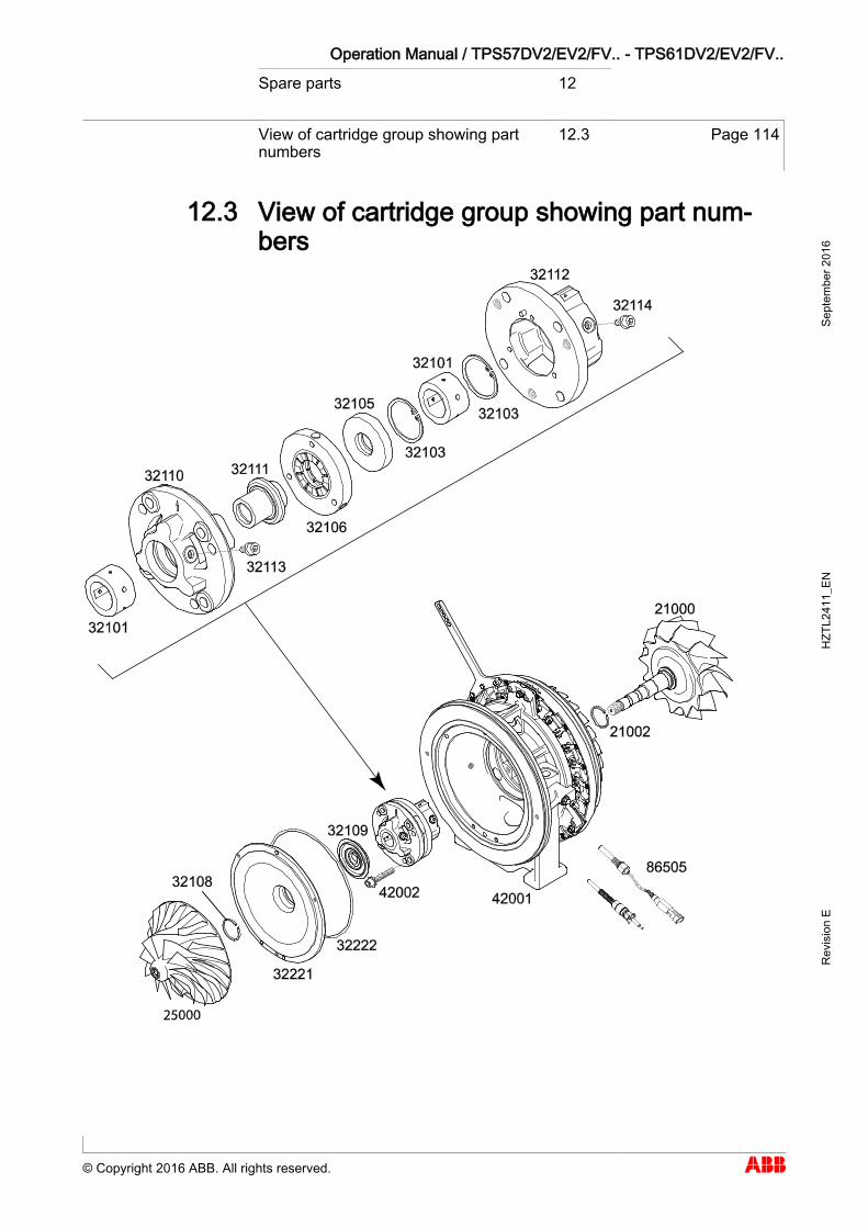
Operation Manual / TPS57DV2/EV2/FV.. - TPS61DV2/EV2/FV.. Spare parts 12
View of cartridge group showing part numbers
12.3 Page 114
© Copyright 2016 ABB. All rights reserved.
Sept
embe
r 201
6 H
ZTL2
411_
EN
Rev
isio
n E
View of cartridge group showing part num-bers 12.3
12.3
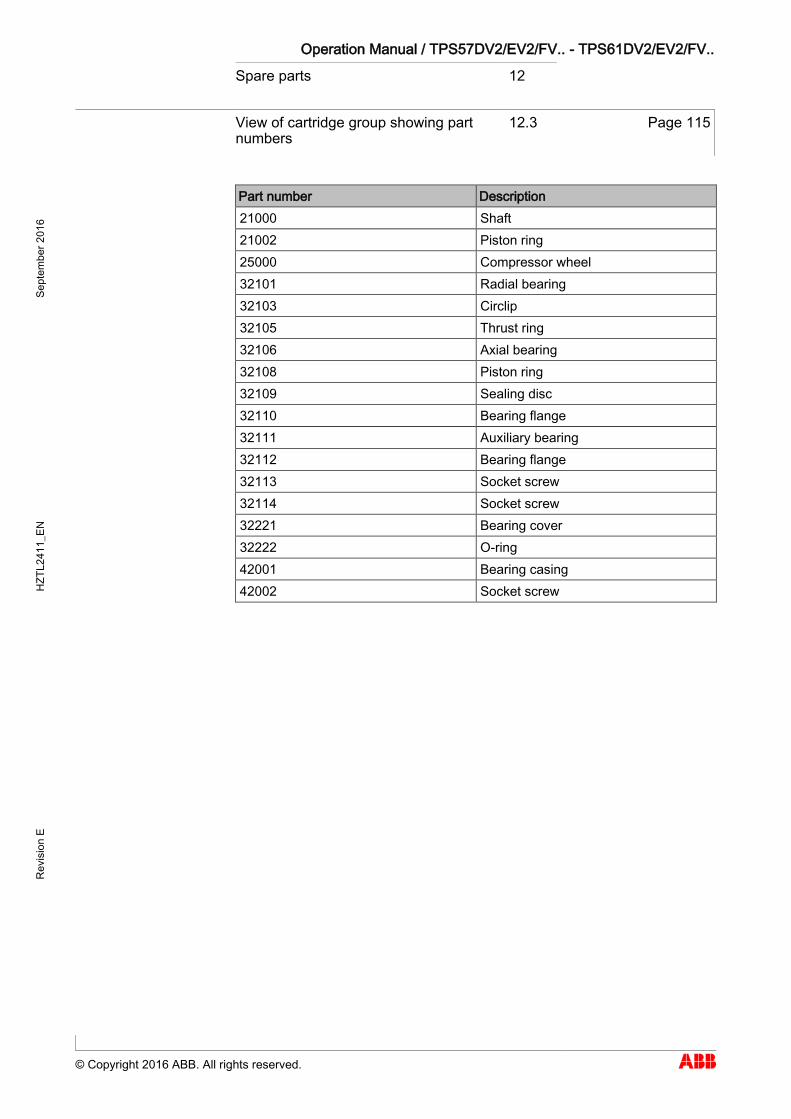
Operation Manual / TPS57DV2/EV2/FV.. - TPS61DV2/EV2/FV.. Spare parts 12
View of cartridge group showing part numbers
12.3 Page 115
© Copyright 2016 ABB. All rights reserved.
Sept
embe
r 201
6 H
ZTL2
411_
EN
Rev
isio
n E
Part number Description 21000 Shaft 21002 Piston ring 25000 Compressor wheel 32101 Radial bearing 32103 Circlip 32105 Thrust ring 32106 Axial bearing 32108 Piston ring 32109 Sealing disc 32110 Bearing flange 32111 Auxiliary bearing 32112 Bearing flange 32113 Socket screw 32114 Socket screw 32221 Bearing cover 32222 O-ring 42001 Bearing casing 42002 Socket screw

������������ ���������� ������� ��������������� ����� �����
���