Embed Size (px)
Citation preview


Sop
pa
lco M
EC
AN
O ROSSS
2
INDICE
Brackets for secondary beams on major beam ……………………………………………………………………………………………………………………….pag. 19
Vertical cross-bracings ……………………………………………………………………………………………………………………….pag. 21
Suspended vertical cross-bracings ……………………………………………………………………………………………………………………….pag. 22
Tie-rods ……………………………………………………………………………………………………………………….pag. 23
Reticulate for beam stiffening ……………………………………………………………………………………………………………………….pag. 23
Parapet railing ……………………………………………………………………………………………………………………….pag. 24
Kickplate ……………………………………………………………………………………………………………………….pag. 25
Flooring ……………………………………………………………………………………………………………………….pag. 26
Stairway ……………………………………………………………………………………………………………………….pag. 28
Stairway landing ……………………………………………………………………………………………………………………….pag. 29
Starway ramp ……………………………………………………………………………………………………………………….pag. 30
Starway handrail ……………………………………………………………………………………………………………………….pag. 31
Stair landing ……………………………………………………………………………………………………………………….pag. 32
Testing of the mezzanine ……………………………………………………………………………………………………………………….pag. 33
Periodical checks and maintenance ……………………………………………………………………………………………………………………….pag. 35
Maintenance and control modality ……………………………………………………………………………………………………………………….pag. 35
Maintenance and control form ……………………………………………………………………………………………………………………….pag. 36

Sop
pa
lco M
EC
AN
O ROSSS
3
Our company, using a wide experience in production and an advanced technology, is able to offer safe and rational solutions to every problem of storage. Our modular structures meet the most stringent load requirements, while providing maximum ease of installation and incredible agility functional. ROSSS was the first Italian company to have obtained the certification for its Quality System according to UNI EN ISO 9001 in branch design and manufacture of metal shelving and then in 2002 we obtained first in Italy, the prestigious ISO 14001 environmental certification, followed by EMAS and SA800. Objectives that underlie an efficient business organization, an absolute thoroughness in all phases of its activities (design, raw materials acquisition, production, installation and after-sales service), the environment and its employees, for the benefit and guarantee of customer. We are part since several years of 'Acai' (Association of Italian Steel) Section Steel Constructors, which has developed a program of selection and self-qualification, we are one of the companies to have passed those tests, and we have been awarded with "Quality Safety CISI" established from Acai to ensure customers the quality and safety of the product in all phases of implementation: from design to after-sales service. We are also the 'only Italian company to have been awarded by official laboratories in Germany who made strict tests on our facilities, obtaining the approval of the German static. For the design and construction of our products we follow the ‘ACAI’ rules as below: and technical standards on New Construction - UNI EN 1993-1-1 – Eurocode 3
Italian and European legislation relating to the design, use and safety of the product: - UNI EN 1993-1-1 - Eurocode 3 Part 1-1: General rules and rules for buildings - UNI EN 1993-1-3 - Eurocode 3 Part 1-3: General rules - Supplementary rules for the use of folded sheet metal sections and cold D. Decree No. 81, 09/04/2008 - Consolidated Security D. Decree No. 172 of 21.05.2004 - Implementation of Directive 2001/95/EC on general product safety;
ISTALLATION N°_______________YEAR OF COSTRUCTION ___________ (delivery note n° /year)
COMPANY
STANDARD REFERENCE

Sop
pa
lco M
EC
AN
O ROSSS
4
Do not place on the mezzanine horizontal loads or dynamic loads either vertical or horizontal. It is not allowed to bump or lean on the mezzanine with trolleys or other means. It is not allowed to use the mezzanine for different purpose other than those described in this manual. The mezzanine is designed for a specific use. Any alterations to the geometry can be made only upon authorization of our Technical Office.
The instructions stated herein are indicative for some details. These particular information are aimed to be extensive for the purposesof the present manual: correct installation of the mezzanine. The exact dimensions are listed in the accompanying documentation. The drawings shown in this manual are presented solely for trade didactic purposes.
MEZZANINE OPERATING LIMITS
NOTICE
In case customer will take care of the assembly directly, Rosss will decline any responsability of damaged to people and
materials.
Our production is covered by insurance guarantees with Assicurazioni Generali Insurance with No 989455770 - "Risk Products" and "Liability" with maximun
amount of € 1,549,370.

Sop
pa
lco M
EC
AN
O ROSSS
5
BEFORE STARTING ASSEMBLY
TOOLS FOR ASSEMBLY
CAUTION
1) ) Check the capacity of the floor and its capacityability to support loads. 2) Check the leveling of the floor surface. 3) Check if there are any interference with existing structures. 4) Check that the available spaces are adequate to ensure the assembly operations can be conducted in safety. 5) The flooring and lighting of the environment should be correct so as to enable staff to work in good conditions.
The assembly team should be trained on such activities and related risks. Assembly team must also be equipped with devices to prevent accidents and provided with personal protection in relation to the specific assembly (helmet, gloves, safety shoes, safety belts, etc.)..
Key sets Level
Screwdriver Crowbar
Rubber hammer Plumb string
Pliers Optical level
Drill Safety belts
Dynamometrical key

Sop
pa
lco M
EC
AN
O ROSSS
6
HANDLING
For the handling of columns and beams during installation you should use only appropriate mechanical means, such as small cranes, winches or other. For columns with less significant lenghts, the handling can be done manually with an appropriate number of people. For all shelves heights, a lift truck must be used to move the material with adequate capacity and for structure assembly a platform with adequate capacity and lift heigh will be required.

Sop
pa
lco M
EC
AN
O ROSSS
7
SEQUENZA DI MONTAGGIO
It is recommended to read carefully the present instruction before starting the assembly.
ASSEMBLY SEQUENCE
To assemble the structure we advise you to follow the steps below: - mounting footplates, main and secondary brackets on the columns - assemble major and minor secondary beams on columns - assemble secondary beams with major beams - assemble flooring and railings - assemble stairs and landings - assemble cross bracings, supporting strut and stiffening elements - assembling of columns and balusters on ground We advise to tighten the bolts at the end of each steps

Sop
pa
lco M
EC
AN
O ROSSS
8
240 290 340 3
90
75
240
290
340
390
75
30
2-3 2-3-4 3-4 4
75
30
75
30
30
BEAMS

Sop
pa
lco M
EC
AN
O ROSSS
9
COLUMNS

Sop
pa
lco M
EC
AN
O ROSSS
10
Fissare il piedino alla colonna con 8 viti M12x30 FOOTPLATE ASSEMBLY
Fix the footplate to the column with 8 screws M12x30
Place the metal plate under the footplate, and then screwing into the floor after the assemblying of the structure.

Sop
pa
lco M
EC
AN
O ROSSS
11
277
277 277
20
0
25
0
30
0
FOR EACH BEAM OF 290 mm
FOR EACH BEAM OF 240 mm
FOR EACH BEAM OF 340 mm
M14
M12
MAJOR PLATES ASSEMBLY
COLUMN 120x120
The major plates have to be joined to the column with bolts M14x40 + nuts and washer; the screwhead must be placed external to the columns. To join beams to major plates use screws M12x35 + nuts and washer. Quantities and placing are shown in this page drawings: red perforations for screws M14, and green ones with screw M12. Note: for the major double plates use screws M14 as above mentioned, but screws M12 have to doubled.

Sop
pa
lco M
EC
AN
O ROSSS
12
COLUMN 150x150
The major plates have to be joined to the column with bolts M14x40 + nuts and washer; the screwhead must be placed external to the columns. To join beams to major plates use screws M12x35 + nuts and washer. Quantities and placing are shown in this page drawings: red perforations for screws M14, and green ones with screw M12. Note: for the major double plates use screws M14 as above mentioned, but screws M12 have to doubled.
FOR EACH BEAM OF 240 mm
330
200
FOR EACH BEAM OF 290 mm
330
250
FOR EACH BEAM OF 340 mm
330
300
M12
M14
FOR EACH BEAM OF 390 mm
405
350
MAJOR PLATES ASSEMBLY

Sop
pa
lco M
EC
AN
O ROSSS
13
Column 150x150 with 2 major double beam
After having assembled the 2 double beams with the brackets for secondary beams, join beams to the column: to do this insert the screws M12x200, interposing between the 2 brackets the tube Ø25 mm; then assemble the second double beams and fix with nuts washer.
N.B. Brackets for secondary beams (see following pages) have to be assembled on double beams before assembling them on the column.
MAJOR PLATES ASSEMBLY

Sop
pa
lco M
EC
AN
O ROSSS
14
COLUMN 200x200
FOR EACH BEAM OF 390 mm
430
350
FOR EACH BEAM OF 340 mm
355
300
M12
M14
FOR EACH BEAM OF 290 mm
355
250
The major plates have to be joined to the column with bolts M14x40 + nuts and washer; the screwhead must be placed external to the columns. To join beams to major plates use screws M12x35 + nuts and washer. Quantities and placing are shown in this page drawings: red perforations for screws M14, and green ones with screw M12. Note: for the major double plates use screws M14 as above mentioned, but screws M12 have to doubled.
MAJOR PLATES ASSEMBLY
Sop
pa
lco M
EC
AN
O ROSSS
15
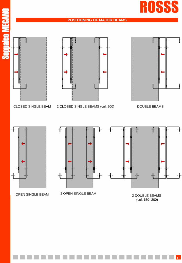
CLOSED SINGLE BEAM 2 CLOSED SINGLE BEAMS (col. 200) DOUBLE BEAMS
2 DOUBLE BEAMS
(col. 150- 200)
OPEN SINGLE BEAM 2 OPEN SINGLE BEAM
POSITIONING OF MAJOR BEAMS

Sop
pa
lco M
EC
AN
O ROSSS
16
Brackets for secondary beams have to be fixed to the column with screw M14x40 + nuts and washer, the screwhead must be placed external to the columns. The secondary beam has to be fixed to the bracket with screw M12x35 + nuts and washer.
In case of double secondary beams, 2 brackets are needed, with the beams joined on one side. N.B. On the column 200x200, also in case of single beam, two secondary bracket are always needed.
In case on the column you have a major plate, the bracket (single or double) has to be fixed on the major plate, using the bolts of the major plate.
BRACKETS FOR SECONDARY BEAMS ON COLUMN

Sop
pa
lco M
EC
AN
O ROSSS
17
FOR BEAM OF 240 mm
FOR BEAM OF 290 mm
M12
M14
FOR BEAM OF 340 mm
FOR BEAM OF 390 mm
Quantities and placing are shown in this page drawings: red perforations for screws M14, and green ones with screw M12. N.B. if the secondary brackets are double, the screws M14 have to be doubled, while the screws M12 remain unchanged.
BRACKETS FOR SECONDARY BEAMS ON COLUMN

Sop
pa
lco M
EC
AN
O ROSSS
18
JOINING COLUMNS-BEAMS
COLUMN 200X200 – 8 BEAMS
COLUMN 200X200 – 2 BEAMS
COLUMN 150X150 – 2 BEAMS
COLUMN 150X150 – 8 BEAMS COLUMN 120X120 – 6 BEAMS
COLUMN 120X120 – 2 BEAMS

Sop
pa
lco M
EC
AN
O ROSSS
19
Fix the bracket to the major beam and the plate to the secondary beam. Then fix the plate to the bracket. Use screw M12x35 + nuts and washer.
In case of secondary double beams two brackets and two plates are needed. The two plates have to be fixed inside the two brackets. The two secondary beams have to be positioned on the same side.
BRACKETS FOR SECONDARY BEAMS ON MAJOR BEAM

Sop
pa
lco M
EC
AN
O ROSSS
20
Quantities and placing of screws M12 are shown in this page drawings. When using a secondary beam smaller than the major one, quantities and placing of screws needed for joining are indicated by the number of holes on the plate.
BRACKETS FOR SECONDARY BEAMS ON MAJOR BEAM

Sop
pa
lco M
EC
AN
O ROSSS
21
Fix the 4-way plate for horizontal cross-bracings at the columns with M12x30 screws, then fix the tie rod; at last pass the tie in the hole of the tie rod and plate and then fix it with 5 D8 clamps.
Tie rod M20
19 edges tie redance
redance N° 5 D8 clamps
PLATES FOR HORIZONTAL
CROSS-BRACINGS
4 WAY
VERTICAL CROSS-BRACINGS

Sop
pa
lco M
EC
AN
O ROSSS
22
Plate for vertical
diagonals
Diagonal 60x5
Example of use of 4 way plate for horizontal diagonals and suspended vertical cross-bracings
In case of suspended vertical cross-bracing, use a plate 60x5 mm, and fix it on the plate, tie rod and plate for vertical diagonals.
Fix the plates for vertical cross-bracings at the columns with M12x30 screws; then fix the tie rod; at last pass the tie in the hole of the tie rod and plate and then fix it with 5 D8 clamps. The plates have to be fixed on a level of about 150 mm from the foot and from the brackets for beams.
Tie rod M20
19 edges tie
4 WAY 3 WAY 2 WAY
VERTICAL CROSS-BRACINGS
SUSPENDED VERTICAL CROSS-BRACINGS

Sop
pa
lco M
EC
AN
O ROSSS
23
Fix the two L-shaped squares on the secundary beams with M12x25 screws, nuts and washer. Then fix to the little squares the beams and the C-shaped profiles with M8x45/80 screws, nuts and 2 washers. At last drill into the C-shaped profiles in the holes on the beams and fix with M8x45 bolts, nuts and 2 washers.
JOINING BRACKETS FOR TIE ROD
150 mm 324 mm
Fix the plate at the upright, then fix the right and left joining brackets at the principal beam. At last fix the tie rod with 2 M12x30 screws.
PLATES FOR TIE-
RODS
2 WAY 3 WAY
TIE-RODS
RETICULATE FOR BEAM STIFFENING

Sop
pa
lco M
EC
AN
O ROSSS
24
Fix the columns on the beams with 2 M10x25 screws. Then insert the tubes, Ø25 mm below and Ø30 mm at the top, then fix them from the inner side with selfscrewing screws M4,2x22. On the angles use curved tubes; these must be fixed on three columns, two on one side and one on the orthogonal side. The curved tubes have to be assembled staggered, in order to have at least one profile fixed on two columns in both ways of the angle. In the picture above you can see the placing of the three elements (in red) which form the angle. All the tubes must be cut on scale during assembly, and the joints have to be calculated in the middle of column.
PARAPET RAILING

Sop
pa
lco M
EC
AN
O ROSSS
25
Put the kickplate on the beam and on the columns, then fix it to all columns with 2 selfscrewing screws M4,2x22. For the finishing of the angle trim one profile during assembly, as showed in the picture below; then lay the two profiles one upon the other and fix them with one selfscrewing screw M4,2x22. After having assembled the flooring, finish off eventual protrusions of the kickplate, in order to remove possible cutting borders. Insert the finishing profile inside the kickplate, then fix it with 2 selfscrewing screws M4,2x22. N.B. Every possible corner has to be finished off in order to avoid possible cutting borders.
KICKPLATE

Sop
pa
lco M
EC
AN
O ROSSS
26
Fix the floor planks to every beam with the bracket and screws M8x20, nuts and washer. The open/closed plank has to be fixed on every beam. Use 1 bracket per 3 planks. The planks have to be joint together with M8x20 screws, nuts and washer, placing one bolt per meter.
OPEN/CLOSED PLANK
WOOD PANELS
OPEN/CLOSED PLANK + WOOD PANEL
Fix the floor plank to every beam as described above, then fix the wood panel to the open/closed plank with screws for wood.
Fix the panels on the beams with the bracket and 2 screws for wood; use two brackets for every panel.
FLOORING

Sop
pa
lco M
EC
AN
O ROSSS
27
Fix the shaped sheet on the beam with selfscrewing screws. Then fix the wood panels with selfscrewing screws on the top of the panel.
SHAPED SHEET + WOOD PANEL
CONNECTION OF WOOD PANELS
For joining together the wood panels use the plastic profile. This profile has to be inserted in the relevant tapping on every side of the panel. The cross-section on this side shows the typical connection between two panels.
FLOORING

Sop
pa
lco M
EC
AN
O ROSSS
28
STAIRWAY

Sop
pa
lco M
EC
AN
O ROSSS
29
Position the upper bracket on the flooring, then fix it on the beam using holes Ø11 mm on the upper part of the beam. The holes on the bracket have to be made during assembly. For fixing use screws M10x40, nuts and washer (a); in case of screws on the beam (b), add more screws M12 to get thickness. Fix the side stair profile on the upper bracket with 6 screws M12x25, nuts and washer (c). Then fix on the side stair profile the two feet with 6 screws M12x25, nuts and washer (d). Assemble the steps by fixing on the profile the two brackets for step support with 4 screws M8x16, nuts and washer (e). At last fix the steps on the side stair profile, starting from the step on the top and downwards. The steps have to be fixed on the side stair profile with 4 screws M12x25, nuts and washer; the buttonhole for adjusting the inclination must be positioned on the back side of the step (f). The number and the pitch of steps is specified in the assembly drawings provided by ROSSS Technical Department.
a
d
e
c
f
b
STAIRWAY landing

Sop
pa
lco M
EC
AN
O ROSSS
30
Fix the side stair profile on the upper bracket with 6 screws M12x25, nuts and washer (c). Then fix the pillars on the lower bracket with 6 screws M12x25, nuts and washer (d). Assemble the steps by fixing on the profile the two brackets for step support with 4 screws M8x16, nuts and washer (e). At last fix the steps on the side stair profile, starting from the step on the top and downwards. The steps have to be fixed on the side stair profile with 4 screws M12x25, nuts and washer; the buttonhole for adjusting the inclination must be positioned on the back side of the step (f). The number and the pitch of steps is specified in the assembly drawings provided by ROSSS Technical Department.
a
c
b
d e
STAIRWAY ramp
Position the lower and upper brackets on the respective flooring, then fix them on the beam using holes Ø11 mm on the upper part of the beam. The holes on the brackets have to be made during assembly. For fixing use screws M10x40, nuts and washer (a); in case of screws on the beam (b), add more screws M12 to get thickness.

Sop
pa
lco M
EC
AN
O ROSSS
31
Fix the columns to the side stair profile with 3 screws M10x25, nuts and washer. Then fix the final column on the upper bracket of the stairway with 2 screws M12x30, nuts and washer. Then insert the tubes in the holes of columns and let them slide till they come inside the final column; fix them on every column with selfscrewing screws M M4,2x22. N.B. the tubes must come out about 20 mm from the last column. Fix the handrail on the columns with the threaded backplate placed inside; fix it on the last column with a selfscrewing screw M4,2x22. The handrail must come out of about 250 mm from the last column. At last insert the plastic caps in the tubes and in the handrail.
For joining the stairway with the banisters, use the holes on the final column, inserting the tubes of Ø25 and Ø30 mm; then fix them with selfscrewing screws M4,2x22.
N.B. Both the handrail and the tubes must be cut off during assembly. The positioning of columns will be specified by the assembly drawings provided by ROSSS Technical Department.
STAIRWAY HANDRAIL

Sop
pa
lco M
EC
AN
O ROSSS
32
Fix each beam on the brackets with 4 screws M12x25, nuts and washer; in case of double stair landing, assemble the intermediate beam as well with the brackets for secondary beam; then assemble the studded open/closed plank, the stairway and the banisters.
STAIR LANDING

Sop
pa
lco M
EC
AN
O ROSSS
33
The test must be executed by personnel with adequate preparation and experience in this field.
In case the test is executed by Rosss, the employed personnel will have been instructed for the specific case.
For the purpose of the test and following the directions related in this manual the following points must be checked:
1) Lay-out of the installation in conformity with Rosss drawing. (if existing)
2) Inspection of columns and beams integrity.
3) Inspection of verticality, alignment and levelling of the mezzanine.
4) Check that the positioning of the banister and/or stairway is as provided.
5) Check of right assembly of the main and secondary brackets.
6) Check of right assembly of cross-bracings and tie rods.
7) Check of right fixing of stair landing.
8) Check of right assembly of the accessory equipment.
9) Check the right application of the capacity labels.
TESTING OF THE MEZZANINE

Sop
pa
lco M
EC
AN
O ROSSS
34
TESTING OF THE MEZZANINE

Sop
pa
lco M
EC
AN
O ROSSS
35
INSPECTIONS
Provide for inspections to single out abnormalities not encountered during normal use of the structure.
Performing scheduled maintenance on the installation, you can avoid dangerous situations that can cause accidents and injuries. Also this will prevent interruptions of activity optimizing the use of the mezzanine.
Planned inspections avoid:
1) Accidents to persons
2) Damages to materials
3) Interruption of production
4) Loss of functionality and consequent economic losses
5) Criminal proceedings against the buyer for not having carried out proper maintenance.
When a situation of immediate danger in the installation is found out, it is advisable to unload the material from the mezzanine in the danger area to avoid accidents to personnel.
The specialized technicians of ROSSS, will start, on request, to examine the problem determining the corrective action to restore the installation in the shortest possible time and with the minimal interruption of activity.
In the operations of maintenance and repair only original spare parts must be used.
It is possible, if you request it, to draw up a maintenance contract so that the controls are carried out by specialized personnel of ROSSS. This will ensure to you maximum utilization of the warranty period and optimal use of the structure while avoiding the dangers caused by occasional interventions performed by unskilled personnel.
Kind of control Periodicity
Columns integrity Yearly
Beams integrity Yearly
Brackets integrity Yearly
Vertical ranging of structure Yearly
Horizontal ranging of structure Yearly
Excessive loads Monthly
Disposition of loads Monthly
Painting Yearly
If these controls reveals anomalies, the total integrity of the mezzanine must be restored as soon as possible, unloading excessive loads or replacing damaged parts.
PERIODICAL CHECKS AND MAINTENANCE
MAINTENANCE AND CONTROL MODALITY

Sop
pa
lco M
EC
AN
O ROSSS
36
Technician Control form department
N° dated shelf
Kind of
controlRegular
Irregular
First Name/Surname
Notes for suggested interventions
MAINTENANCE AND CONTROL FORM

Sop
pa
lco M
EC
AN
O ROSSS
37
N° DateInternal
intervention
Description
intervention
Doc. Details of
intervention
REGISTER OF MAINTENANCE INTERVENTIONS