Embed Size (px)
Citation preview

Near-field characterization of guided polariton propagationand cutoff in surface plasmon waveguides
Rashid Zia,* Jon A. Schuller, and Mark L. BrongersmaGeballe Laboratory for Advanced Materials, Stanford University, Stanford, California 94305, USA
�Received 22 December 2005; revised manuscript received 14 August 2006; published 25 October 2006�
We present a series of near-field experiments characterizing cutoff for the three lowest order leaky surfaceplasmon modes supported by Au stripes on glass substrates. These studies demonstrate that the propagation oflight along surface plasmon waveguides is mediated by a discrete number of guided polariton modes as well asa continuum of radiation modes. To distinguish the contribution of the guided modes from that of the radiationcontinuum, a parametric study of propagation length as a function of varying stripe width is performed.Discontinuities consistent with the loss of a guided mode are observed near cutoff widths predicted by nu-merical simulations, and a severe decrease in propagation length is observed below cutoff for the fundamentalsurface plasmon mode. Contrary to previous interpretations, experimental and numerical investigations confirmthat the finite propagation lengths observed along the narrowest stripes are in good agreement with an intuitivemodel for the radiation continuum. Furthermore, multimode interference studies provide direct evidence formultiple guided modes and support previous findings with regard to modal cutoff.
DOI: 10.1103/PhysRevB.74.165415 PACS number�s�: 73.20.Mf, 78.66.Bz, 42.79.Gn, 07.79.Fc
I. INTRODUCTION
Surface plasmon-polaritons �SPPs� have received consid-erable attention for their ability to guide electromagnetic en-ergy at optical frequencies.1–3 In particular, researchers haveproposed the use of surface plasmon waveguides to transportlight below the diffraction limit of conventional dielectricoptics.4–7 The best studied surface plasmon waveguides todate have been finite width metal stripes on dielectric sub-strates, which have been the topic of numerous near-fieldmicroscopy studies.8–13 Initial experimental results have sug-gested that subwavelength metal stripes may support highlyconfined surface plasmon modes.10,13 However, recent nu-merical studies have shown that there is a cutoff conditionfor metal stripe waveguides and that no guided surface po-lariton modes are supported along subwavelength metalstripes.14 These results suggest that guided polariton modesare insufficient to describe the observed propagation of lightalong metal stripe waveguides.
It is well known that a complete description of lightpropagation in dielectric waveguides requires a continuum ofradiation modes in addition to a discrete number of guidedsolutions.15,16 Here, we demonstrate that a similar descriptionmay be used for the propagation of light along surface plas-mon waveguides. To introduce this description, we leveragea recently derived dielectric waveguide model for guidedsurface polaritons.17 This model describes how the total in-ternal reflection of SPPs at the edge of a metal film �asshown in Fig. 1�a�� may lead to the existence of guided sur-face polariton modes in a metal stripe of finite width, asshown in Fig. 1�b�. Similar to the modes of a dielectric slabwaveguide, SPPs along the finite width stripe must construc-tively interfere upon total internal reflection to form a guidedmode. This interference condition establishes an eigenvalueproblem with a discrete set of modal solutions. In contrast,SPPs incident below the critical angle for total internal re-flection may be transmitted into the external dielectric region�as shown in Fig. 1�c��. This transmission forms the basis for
radiation modes, and an example is shown in Fig. 1�d�.Given the continuous range of possible angles below thecritical condition for total internal reflection, these solutionsform a continuum of radiation modes. Although the fieldsassociated with the radiation continuum extend well beyondthe finite width stripe, these solutions may contribute to thelocal optical field in the vicinity of the waveguide.
While previous experimental results have been mainly as-sociated with the guided polariton modes explored by nu-merical studies,14,18–20 it is likely that near-field measure-ments of the local optical intensity probe the radiationcontinuum as well. In the following paper, we present a se-ries of near-field experimental studies characterizing guidedpolariton propagation along metal stripe surface plasmonwaveguides. Using a photon scanning tunneling microscope�PSTM�,21 we image light propagation along finite width Austripes on glass substrates. To distinguish the guided modesfrom the radiation continuum, we perform a parametric studyof propagation length as a function of stripe width. Consis-tent with the discrete nature of the guided solutions, we ob-serve discontinuities in the propagation length near predictedcutoff widths for the three lowest order surface plasmonmodes. Furthermore, below cutoff for the fundamentalguided mode, we observe propagation lengths that are con-sistent with a simple, width-independent model for lightpropagation via the radiation continuum. Cutoff widths forthe higher order modes are further investigated by multi-mode interference studies, and all results are shown to be ingood agreement with numerical simulations.
II. EXPERIMENTAL TECHNIQUE
Similar to previous experimental studies,8–13 we use aPSTM �Ref. 21� to probe the localized light intensity abovemetal stripe waveguides. Samples were prepared lithographi-cally on glass substrates such that thin Au stripes protrudefrom extended thin film regions which serve as launchpads.To excite surface plasmon modes along the metal stripes,
PHYSICAL REVIEW B 74, 165415 �2006�
1098-0121/2006/74�16�/165415�12� ©2006 The American Physical Society165415-1
SPPs are first excited at the top air-metal interface of theextended thin film region by attenuated total reflection �ATR�in the Kretschmann configuration.22 These SPPs then propa-gate though a tapered region to the stripe waveguides wherethey can excite guided polariton modes as well as radiationmodes. By scanning a near-field optical probe at a constantheight of 100 nm above the sample, one can map the propa-gation of light along the metal stripe.
A schematic of the PSTM used for this study is shown inFig. 2. This instrument has been constructed by modifying acommercially available scanning near-field optical micro-scope ��-SNOM; WITec GmbH; Ulm, Germany�. The modi-fied microscope is a variation on the conventional PSTMwhich has been used extensively to characterize SPP propa-gation along extended films as well as metal stripewaveguides.8–13,23,24 In a conventional PSTM, SPPs are ex-cited via ATR using prism coupling, and the local opticalfields are probed by scanning a tapered fiber tip above thesample. Our PSTM operates in a similar fashion, except forthree modifications. First, in the place of a prism, a partiallyilluminated high numerical aperture total internal reflectionfluorescence �TIRF� objective �Zeiss Alpha Plan-Fluar,100X, NA=1.45� is used to excite SPPs on the Au launch-pad. Second, an aluminum-coated apertured cantilever with a100 nm opening at the base of a hollow pyramidal tip is usedas an optical near-field probe as opposed to a tapered opticalfiber.25 Third, instead of scanning the cantilever above a sta-tionary sample, the sample and illumination objective arescanned on an x ,y ,z piezostage beneath the apertured canti-lever probe. Although the presence of a near-field probe nec-essarily perturbs the SPP fields, we assume such as previousworks on surface plasmon waveguides that these effects aresmall,8–13 and will later show that the measured field distri-butions are in good agreement with numerical simulations ofthe SPP fields in the absence of any perturbations.
The studied metal stripe waveguides were fabricated us-ing electron-beam lithography. In order to prevent complica-tions arising from additional materials, the following processwas developed to produce pure Au structures on glass sub-strates without the need for an adhesion layer such as chro-
mium or an intermediate anticharging layer such as indiumtin oxide �ITO�. Due to the short working distance of theTIRF objective, samples were fabricated on 150–180 �mthick coverslips made of S1-UV grade fused silica. Cleanedsubstrates were spin-coated with a 100 nm thick layer ofpolymethyl methacrylate �PMMA, 950 K molecular weight�.To prevent sample charging, a 45 Å layer of chromium wasdeposited on top of the cured PMMA, and followingelectron-beam exposure, the Cr layer was removed with a
FIG. 1. Simple ray optics schematics for themodes of a metal stripe waveguide. Total internalreflection of a surface polariton wave, �a�, maylead under proper interference conditions to aguided surface polariton mode, �b�. Surface po-lariton waves may also be transmitted, �c�, whichnecessarily leads to a radiation mode �d�. Notethat the radiation mode must appear to have asource outside of the waveguide to be an eigen-mode of the system, as depicted by the dashedlines.
FIG. 2. �Color online� Schematic of photon scanning tunnelingmicroscope �PSTM�. A partially illuminated high numerical aper-ture objective is used to excite surface plasmon-polaritons along theAu-Air interface via attenuated total reflection. Light is scatteredfrom these surface waves by an aperture cantilever probe and de-tected by a photomultiplier tube. Note that the sample and illumi-nation objective are rigidly mounted to a x ,y ,z piezostage which isscanned below the fixed cantilever.
ZIA, SCHULLER, AND BRONGERSMA PHYSICAL REVIEW B 74, 165415 �2006�
165415-2

standard, acetic-acid based etchant. To ensure Au adhesion tothe glass substrate, the developed samples were cleaned us-ing a low power oxygen plasma �1–2 W/in2 at 100 mTorroxygen pressure� for 10 sec to remove residual water andhydrophilic silanol groups from the exposed glass surface.Samples were then immediately loaded into a vacuum cham-ber for metallization, and after reaching a base pressure be-low 10−7 Torrs, a 48 nm thick layer of Au was deposited viaelectron-beam evaporation. Fabrication was completed bystandard liftoff of the remaining PMMA, and the resultingsamples consisted of patterned 48 nm Au structures whichdirectly adhered to the fused silica coverslips without anyadhesion or anti-charging layers.
III. PARAMETRIC STUDY OF PROPAGATION LENGTHS
Using the aforementioned PSTM, we have mapped thepropagation of light along varying width Au stripes on glass
substrates. Fifteen different stripe widths were investigatedranging from 500 nm to 6 �m. Figure 3 shows characteristicnear-field images for the eight narrowest stripe widths. Simi-lar to previous far-field measurements along Ag stripes,26 itappears that the observed propagation length decreases as afunction of decreasing stripe width. This general behavior isin good agreement with previous numerical solutions for theleaky surface plasmon modes supported by the top air-metalinterface of Au stripe waveguides.14 However, we can antici-pate additional features in this study of propagation lengthsthat may distinguish guided polariton propagation by its dis-crete nature. In particular, a metal stripe waveguide can sup-port a finite number of guided modes. While wide stripesmay support multiple guided modes, narrower stripes maysupport none. In the following sections, we will show howthese finite variations in mode number may be used to dis-tinguish the discrete guided modes from the radiation con-tinuum.
FIG. 3. �Color online� Experimental near-field images of surface plasmon propagation along varying width metal stripe waveguidesranging from 0.5 �m to 3.5 �m.
NEAR-FIELD CHARACTERIZATION OF GUIDED… PHYSICAL REVIEW B 74, 165415 �2006�
165415-3

A. Discrete nature of the guided modes
To quantify the propagation length, previous studies havecommonly fit observed intensity profiles to a single decayingexponential �i.e., �E�2�Ae−y/L+c, where y denotes positionalong the direction of propagation, L is the 1/e decay lengthfor intensity, and c is an offset constant generally associatedwith background noise�. Such analysis provides a qualita-tively useful measure of propagation length, but the singleexponential decay is an imprecise description when multiplemodes are excited. As we vary the stripe width, we anticipatethis inaccuracy will be most noticeable in regions wherethere is a transition in the number of allowed modes. In thecontext of waveguide theory, the electric field in a regionsupporting N number of guided modes may be described bythe following expression:
E� �x,y,z� = �n=1
N
an�� n�x,z�ei��n+i�n�y
+ �0
+� �0
k0
bk�,k���
k�,k��x,z�ei�k�+ik��ydk�dk�,
�1�
where the summation and integral terms denote the contribu-tion of the guided modes and the radiation continuum,respectively.27 Each guided �radiation� mode is described byan amplitude coefficient an �bk�,k��, transverse mode profile
�� n�x ,z���� k�,k��x ,z��, and complex propagation constant ��n
+ i�n���k�+ ik���. Note that the summation term in Eq. �1�reflects the discrete nature of the guided polariton modes.Ignoring for the time being the contribution of the radiationcontinuum, we may recognize how this discrete nature influ-ences the relationship between the physical decay constants��n� and the phenomenological propagation length �L�. Forthe case of a single guided mode �e.g., N=1�, the propaga-tion length is directly related to the mode’s decay constant�e.g., L=1/2�1�. For the case of multiple modes however,the fit will depend upon the relative intensities of the sup-ported modes, and the propagation length more closely ap-proximates a weighted average of the decay constants.Therefore for varying stripe widths, the propagation lengthwill reflect not only changes in the decay constants, but alsochanges in the number of supported modes. As cutoff of aguided mode may dramatically alter a weighted average ofthe decay constants, we may anticipate discontinuities in theobserved propagation length as a function of stripe width.
While discontinuities were not reported in previous far-field measurements,26 the enhanced spatial resolution offeredby near-field techniques has allowed us to observe such be-havior. To calculate propagation lengths from the near-fieldimages, we have integrated the light intensity along thewidth of each stripe and fit the resulting curve with a simpleexponential decay, as follows:
�−W/2
W/2
�E�x,y,z = h0��2dx � Ae−�y�/L + c . �2�
The integration here serves to average the light intensityalong the stripe width.28 Figure 4 shows the fit propagation
length �L� as a function of stripe width �W�. Using the full-vectorial finite difference method described previously inRef. 14, we have also solved for leaky surface plasmonmodes supported by these stripes. Alongside the experimen-tal data, we plot the calculated decay behavior for the threelowest order surface plasmon modes. Vertical lines havebeen used to denote the calculated cutoff widths for the first,second, and third order modes near 1.25 �m, 3 �m, and5 �m, respectively. Note that for wider stripes �i.e., W�3 �m�, the observed propagation length falls within therange of values predicted by these numerical simulations.For these stripe widths, we also observe the expected discon-tinuities near cutoff for the higher order guided modes.While the propagation length tends to decrease with decreas-ing stripe width, there are two increases that oppose thistrend. The propagation lengths for stripe widths between4 �m and 5 �m are higher than those for wider stripes, andthe propagation length increases slightly as stripe widths arereduced from 3 �m to 2.5 �m. These increases are consis-tent with cutoff for the lossier third and second order surfaceplasmon modes, respectively. As higher order modes are cut-off, the observed propagation length increasingly reflects thelower loss fundamental mode. Below the predicted cutoff ofthe fundamental guided mode, we observe a severe disconti-nuity. As stripe widths are reduced from 1.25 �m to 1 �m,the propagation length drops significantly from9.6 �m to 4.8 �m. Unlike cutoff for the higher order modeswhere there still exist lower order modes with reducedlosses, it is not surprising that cutoff of the fundamentalguided mode results in a severe decrease in propagationlength. This third discontinuity again reflects the discrete na-ture of the guided solutions, but also represents a transitionto a new regime in which there are no guided modes at all.
B. Contribution of the radiation continuum
Below the predicted cutoff width for the fundamental sur-face plasmon mode, it is not surprising that we continue to
FIG. 4. �Color online� Surface plasmon propagation length as afunction of stripe width at 780 nm for Au stripes on glass sub-strates. Circular markers denote experimental data with error barsdetermined by 95% tolerance intervals. The solid, dashed, and dot-ted curves show the calculated decay behavior for the three lowestorder leaky surface plasmon modes supported by these stripes, andthe associated vertical lines denote the predicted cutoff widths forthese mode. Note that numerical solutions were obtained using thefull-vectorial finite-difference method described in Ref. 14 for48 nm thick Au stripes ��Au=−24.13+1.725i� �Ref. 29� on a glasssubstrate ��glass=2.25�.
ZIA, SCHULLER, AND BRONGERSMA PHYSICAL REVIEW B 74, 165415 �2006�
165415-4

observe finite propagation lengths. The lack of guided modesalong narrow stripes does not imply that light cannot propa-gate nor that propagation cannot be observed. Even in theabsence of a metal stripe �i.e., the limiting case of infinitesi-mal stripe width�, the termination of the tapered launchpadpresents a discontinuity which should scatter SPPs into free-space radiation,30 and this scattered light may be detected byour PSTM at short distances from the launchpad edge. De-spite experimental differences with previous near-field stud-ies, it is interesting to note that the observed propagationlengths for narrow stripes �i.e., W�1 �m� in Fig. 4 are com-parable to previous reports for subwavelength stripes.10,13
Given the presence of distinctive interference patterns withsubwavelength periodicities,10 previous studies attributed theobserved propagation lengths along narrow metal stripes toguided polariton modes. However, we suggest an alternativephysical interpretation. By leveraging an intuitive physicalmodel, we will demonstrate that the finite propagationlengths which we have observed for narrow stripes are con-sistent with both experimental and numerical models for thecontribution of the radiation continuum.
In the context of modal theory, all nonguided pathwaysare described by the integral term for the radiation con-tinuum in Eq. �1�. As it is impractical to explicitly derive theamplitude coefficients, transverse mode profiles and propa-gation constants for all of the radiation modes, we recall thesimple physical model presented in Fig. 1. In this model, theradiation modes may be decomposed into SPPs propagatingalong the metal stripe at variety of angles below the criticalcondition for total internal reflection. In the lateral direction,these SPPs are confined to the metal stripe by a small effec-tive index gradient �kspp=1.022k0; neff=1.022�.17 Thus, asshown in Fig. 5�a�, these SPPs can radiate laterally from the
stripe by coupling to homogenous waves in the surroundingdielectric region. Although the precise modes will dependupon the boundary conditions imposed by the stripe’s edges,the resulting radiation pattern can be modeled by means ofthe free-space approximation.31 For weakly guided dielectricstructures, the radiation modes are often described as pertur-bations from the free-space modes within a uniform dielec-tric cladding.32 In this manner, the radiation modes excited atthe input of a metal stripe can be modeled by the light scat-tered into free-space from the terminated taper shown in Fig.5�b�. In Fig. 5�c�, we present a near-field image of lightscattered from a terminated taper, and despite the absence ofa stripe, the light intensity appears to have lateral definition.To compare this model case for the radiation modes with theobserved propagation along metal stripes, the cross-sectionshown in Fig. 5�d� has been fit to an exponential decay. Theresulting propagation length of 3.25 �m is in good agree-ment with the lengths observed for our two narrowest stripes.We further check the validity of the model against a numeri-cal solution based on vector diffraction theory.30,33 Using thenormal mode analysis outlined in Ref. 32, we have solvedfor the scattered fields from an extended edge discontinuity.The calculated intensity decay is plotted in the inset of Fig.5�d� alongside a fit exponential decay function with a propa-gation length of 2.6 �m. Therefore, both experimental andnumerical investigation of the free-space modes well ap-proximate the finite propagation observed for narrow stripes,and this agreement suggests that radiation modes rather thanguided modes account for the observed propagation alongsubwavelength stripes. Accordingly, we can conclude that acomplete description of the measured near-field intensityalong metal stripe waveguides requires both the discreteguided solutions as well as the continuum of radiationmodes.
FIG. 5. �Color online� Characterization of theradiation modes using the free-space approxima-tion: �a� the radiation modes excited at the inputof a metal stripe waveguide may be modeled tofirst order by �b� the free-space modes excited atthe end of tapered launch-pad. Even without astripe, the experimental near-field image at theend of taper �c� appears to show light propagationalong the y axis, and �d� a cross section along thedashed line can be well fit to an exponential de-cay. The fit propagation length �3.25 �m� is ingood agreement with the propagation length pre-dicted by numerical simulations of scattered lightabove an extended edge discontinuity �2.6 �m�as shown in the inset.
NEAR-FIELD CHARACTERIZATION OF GUIDED… PHYSICAL REVIEW B 74, 165415 �2006�
165415-5

IV. MULTIMODE INTERFERENCE STUDIES
In addition to distinct decay constants ��n�, each guidedpolariton mode is described by a unique transverse mode
profile ��� n�x ,z�� and phase constant ��n�. By leveraging lat-eral symmetries associated with the mode profiles, we haveperformed a parametric study of multimode interference forvarying width stripes. Multimode interference is commonlyexploited in the design of couplers and dividers for applica-tions in integrated optics.34 In the present context though,multimode interference may also be used to characterize themodes supported by a complex waveguide structure.35
Figure 6 shows the simulated mode profiles for the leakysurface plasmon modes supported by three varying width Austripe waveguides. While the 2 �m wide stripe supports onlya single mode with even lateral symmetry, the wider 4 �mand 6 �m stripes also support a second order mode with anodd lateral symmetry. Note that the phase constant associatedwith this higher order mode is smaller than that of the fun-damental mode, and thus, if both modes are excited simulta-neously, one observes a beating in the propagation direction.To demonstrate this interference, we can excite a 4 �m widewaveguide using a single mode 2 �m input stripe. When theinput stripe is centered with respect to the larger waveguideas shown in Fig. 7�a�, we primarily excite the fundamentalmode. However, when the input stripe is fabricated off-centerwith respect to the larger waveguide as shown in Fig. 7�b�,both supported modes are excited. As evidenced by the lat-eral cross-sections of Fig. 7�d�, there is a clear shift in the
transverse intensity profile as light propagates down thestripe. Near the input region, the lateral profile shows asingle peak to the right of the dashed centerline; this profileis consistent with a superposition of the even first ordermode and the odd second order mode. Further down thestripe though, the intensity of this initial peak diminishes,and an additional peak to the left of the centerline emerges.At the end of the 35 �m long stripe, it appears that the op-tical intensity has switched to the other side of the 4 �mwaveguide. This lateral transition is consistent with a phase shift in the relative phases for the first and secondorder modes, and the length scale for this transition is ingood agreement with the beat length predicted by numericalsimulations �i.e., / ��1−�2��38 �m�.
For wider stripes, a third order leaky surface plasmonmode may also be supported. As shown in Fig. 6�f�, thismode has three lateral intensity peaks in the dominant Hxfield profile and an even lateral symmetry. Again, we mayexploit the parity difference to demonstrate multimode inter-ference. Similar to the previous case shown in Fig. 7�a�, weuse a centered 2 �m wide stripe as the input for a largerwaveguide to minimize excitation of the second order oddmode. In Fig. 8�a�, we can observe multimode inference asthe excited 6 �m stripe supports two even surface plasmonmodes, a fundamental mode with a single lateral peak as wellas the third order with three peaks. Near the stripe input, therelative phase of the two modes is such that they interfere toform a single peak at the stripe center. With propagationthough, a relative phase shift is incurred such that afterpropagating 30 �m there is a local minima along the center
FIG. 6. �Color online� Simulated field profiles for the leaky surface plasmon modes supported by 2, 4, and 6 �m Au stripe waveguidesusing the full-vectorial finite-difference method described in Ref. 14 ��Au=−24.13+1.725i for =780 nm� �Ref. 29�. Insets depict the lateralmode profiles predicted by equivalent dielectric slab waveguides as outlined in Ref. 17. The core index of the dielectric slabs was determinedby the effective index of the leaky SPP mode supported along an infinitely wide 48 nm thin Au film on a glass substrate �neff=kspp/k0
=1.022+0.003i, calculated using the reflection pole method� �Ref. 37�.
ZIA, SCHULLER, AND BRONGERSMA PHYSICAL REVIEW B 74, 165415 �2006�
165415-6

of the stripe between two lateral peaks. Again, the observedbeat length is in good agreement with the value predicted byfull-vectorial simulations of the guided polariton modes �i.e., / ��1−�3��29 �m�. Although the leaky nature of theguided polariton modes does not allow for simple normaliza-tion, we can leverage the dielectric waveguide model fromRef. 17 to calculate approximate lateral mode profiles for usein simple beam propagation calculations.36 The observednear-field intensity in Fig. 8�a� is well modeled by multi-mode interference of the equivalent dielectric structure asshown in Fig. 8�b�.
Accordingly, the combined experimental and numericalresults shown in Figs. 6–8 unambiguously demonstrate theexistence of higher order surface plasmon modes. To furthersupport our previous findings with respect to guided modecutoff, we have performed parametric studies of multimodeinterference along varying width metal stripe waveguides.
A. Cutoff for the odd second order mode
To investigate cutoff for the second order surface plasmonmode, waveguides ranging in width �W� from
FIG. 7. �Color online� Experimental demon-stration of multimode interference between thetwo guided modes supported by a 4 �m wide Austripe as excited by a 2 �m wide input stripe. Thedashed white lines indicate the outline of the Austructures. Frames �a� and �b� show near-field im-ages acquired for symmetric and asymmetricalignment of the input stripe, respectively.Frames �c� and �d� show cross sections of thedata shown in �a� and �b�, respectively. Initialcross sections show the intensity above the inputstripe �acquired at y=−1 �m�, and subsequentcross sections are taken at 2.5 �m intervals �be-ginning with y=−2.5 �m� and offset by −0.25increments.
NEAR-FIELD CHARACTERIZATION OF GUIDED… PHYSICAL REVIEW B 74, 165415 �2006�
165415-7

2.5 �m to 4 �m were fabricated with an off-center inputstripe. The width of each input stripe was set to half of thevalue for wider waveguide such that the left edge could bealigned along the center of the larger waveguide while theright edges were continuous. For wider stripes, such asym-metric excitation clearly excited both the even and odd paritysurface plasmon modes. In Fig. 9�a�, the near-field image fora 3.5 �m stripe waveguide is shown. As with the earlierexample in Fig. 7�b�, there is a shift in the lateral intensityprofile from one side of the waveguide to the other, and theobserved beat length of approximately 28 �m is in goodagreement with numerical simulations �i.e., /���31 �m�.
For the narrower 3 �m wide waveguide shown in Fig. 9�b�,the multimode interference is more difficult to distinguish.However, from the lateral cross sections shown in Fig. 9�e�,one can observe the transition from a single lateral peak tothe right of the centerline near the input to a pronouncedpeak to the left of the centerline near the predicted beatlength of 25 �m. As the stripe width was reduced further,evidence of multimode interference was not observed. Fig.9�c� shows an example case for a 2.5 �m stripe. Near theinput region, there is a shift in the lateral intensity as the SPPdiffract onto the wider stripe, but despite some undulations inintensity, the lateral profile does not appear to shift from side
FIG. 8. �Color online� Demonstration of mul-timode interference between the two guidedmodes supported by a 6 �m wide Au stripe: �a�experimental near-field image; �b� simulatednear-field intensity for an equivalent dielectricwaveguide system calculated for the approximatemodes shown in the insets of Figs. 6�a�, 6�d�, and6�f�. The dashed white lines indicate the outlineof the Au structures. Frames �c� and �d� showcross sections of the data shown in �a� and �b�,respectively. Initial cross sections show the inten-sity above the input stripe �acquired at y=−1 �m�, and subsequent cross-sections are takenat 2.5 �m intervals �beginning with y=−2.5 �m�and offset by −0.25 increments.
ZIA, SCHULLER, AND BRONGERSMA PHYSICAL REVIEW B 74, 165415 �2006�
165415-8

FIG. 9. �Color online� Experimental multimode interference study to investigate the cutoff width for the second order leaky surfaceplasmon mode. The dashed white lines indicate the outline of the Au structures. Frames �a�, �b�, and �c� show near-field images acquiredstripe widths of 3.5 �m, 3 �m, and 2.5 �m, respectively. Frames �d�, �e�, and �f� show cross sections of the data shown in �a�, �b�, and �c�,respectively. Initial cross sections show the intensity above the input stripe �acquired at y=−1 �m�, and subsequent cross-sections are takenat 2.5 �m intervals �beginning with y=−2.5 �m� and offset by −0.25 increments.
NEAR-FIELD CHARACTERIZATION OF GUIDED… PHYSICAL REVIEW B 74, 165415 �2006�
165415-9

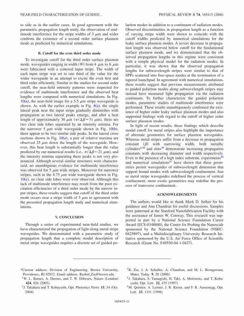
FIG. 10. �Color online� Experimental multimode interference study to investigate the cutoff width for the third order leaky surfaceplasmon mode. The dashed white lines indicate the outline of the Au structures. Frames �a�, �b�, and �c� show near-field images acquiredstripe widths of 5.5 �m, 5 �m, and 4.75 �m, respectively. Frames �d�, �e�, and �f� show cross sections of the data shown in �a�, �b�, and �c�,respectively. Initial cross-sections show the intensity above the input stripe �acquired at y=−1 �m�, and subsequent cross-sections are takenat 2.5 �m intervals �beginning with y=−2.5 �m� and offset by −0.25 increments.
ZIA, SCHULLER, AND BRONGERSMA PHYSICAL REVIEW B 74, 165415 �2006�
165415-10
to side as in the earlier cases. In good agreement with theparametric propagation length study, the observation of mul-timode interference for the stripe widths of 3 �m and widerconfirms the existence of a second order surface plasmonmode as predicted by numerical simulations.
B. Cutoff for the even third order mode
To investigate cutoff for the third order surface plasmonmode, waveguides ranging in width �W� from 4 �m to 6 �mwere fabricated with a centered input stripe. The width ofeach input stripe was set to one third of the value for thewider waveguide in an attempt to excite the even first andthird order efficiently. Similar to the studies for second ordercutoff, the near-field intensity patterns were inspected forevidence of multimode interference and the observed beatlengths were compared with numerical simulations. In Fig.10�a�, the near-field image for a 5.5 �m stripe waveguide isshown. As with the earlier example in Fig. 8�a�, the singlelateral peak near the input stripe gradually diminishes withpropagation as two lateral peaks emerge, and after a beatlength of approximately 30 �m � /���31 �m�, there aretwo clear side lobes separated by an intensity minima. Forthe narrower 5 �m wide waveguide shown in Fig. 10�b�,there appear to be two similar side peaks. In the lateral crosssections shown in Fig. 10�e�, a pair of relative maxima areobserved 25 �m down the length of the waveguide. How-ever, this beat length is substantially longer than the valuepredicted by our numerical results �i.e., /���21 �m�, andthe intensity minima separating these peaks is not very pro-nounced. Although several similar structures were character-ized, no unambiguous evidence for multimode interferencewas observed for 5 �m wide stripes. Moreover for narrowerstripes, such as the 4.75 �m wide waveguide shown in Fig.10�c�, no clear side lobes were ever observed. Although thislack of multimode interference may result from the poor ex-citation efficiencies of a third order mode by the narrow in-put stripes, these results suggest that cutoff of the third ordermode occurs near a stripe width of 5 �m in agreement withthe presented propagation length study and numerical simu-lations.
V. CONCLUSION
Through a series of experimental near-field studies, wehave characterized the propagation of light along metal stripewaveguides. We demonstrated with a parametric study ofpropagation length that a complete modal description ofmetal stripe waveguides requires a discrete set of guided po-
lariton modes in addition to a continuum of radiation modes.Observed discontinuities in propagation length as a functionof varying stripe width were shown to coincide with thecutoff widths predicted by numerical simulations for theleaky surface plasmon modes. A severe decrease in propaga-tion length was observed below cutoff for the fundamentalsurface plasmon mode, and we demonstrated that the ob-served propagation lengths in this regime were consistentwith a simple physical model for the radiation modes. Inparticular, it was shown that the observed propagationlengths for subwavelength stripes were similar to that ofSPPs scattered into free-space modes at the termination of atapered launchpad. In agreement with numerical simulations,these results suggest that previous measurements attributedto guided polariton modes along subwavelength stripes mayinstead have measured light propagation via the radiationcontinuum. To further characterize the guided polaritonmodes, parametric studies of multimode interference wereperformed. These results unambiguously confirmed the exis-tence of higher order leaky surface plasmon modes and alsosupported findings with regard to the cutoff of higher ordersurface plasmon modes.
In light of recent results, these findings which describemodal cutoff for metal stripes also highlight the importanceof alternate geometries for surface plasmon waveguides.Whereas metal stripes suffer from a decrease in propagationconstant ��� with narrowing width, both metalliccylinders4,38 and slots39 demonstrate increasing propagationconstants with decreasing diameter and width respectively.Even in the presence of a high index substrate, experiments40
and numerical simulations41 have shown that these geom-etries permit waveguides of subwavelength dimension thatsupport bound modes with subwavelength confinement. Justas metal stripe waveguides redefined the process of verticalconfinement, more exotic geometries may redefine the pro-cess of transverse confinement.
ACKNOWLEDGMENTS
The authors would like to thank Mark D. Selker for hisguidance and Anu Chandran for useful discussions. Sampleswere patterned at the Stanford Nanofabrication Facility withthe assistance of James W. Conway. This research was sup-ported in part by a National Science Foundation CareerAward �ECS-0348800�, the Center for Probing the Nanoscalesponsored by the National Science Foundation �NSEC-0425897�, and a Multidisciplinary University Research Ini-tiative sponsored by the U.S. Air Force Office of ScientificResearch �Grant No. F49550-04-1-0437�.
*Current address: Division of Engineering, Brown University,Providence, RI 02912. Email address: Rashid�[email protected]
1 W. L. Barnes, A. Dereux, and T. W. Ebbesen, Nature �London�424, 824 �2003�.
2 J. Takahara and T. Kobayashi, Opt. Photonics News 15, 54 �Oct.2004�.
3 R. Zia, J. A. Schuller, A. Chandran, and M. L. Brongersma,Mater. Today 9, 20 �2006�.
4 J. Takahara, S. Yamagishi, H. Taki, A. Morimoto, and T. Koba-yashi, Opt. Lett. 22, 475 �1997�.
5 M. Quinten, A. Leitner, J. R. Krenn, and F. R. Aussenegg, Opt.Lett. 23, 1331 �1998�.
NEAR-FIELD CHARACTERIZATION OF GUIDED… PHYSICAL REVIEW B 74, 165415 �2006�
165415-11

6 J. C. Weeber, A. Dereux, Ch. Girard, J. R. Krenn, and J. P. Gou-donnet, Phys. Rev. B 60, 9061 �1999�.
7 M. L. Brongersma, J. W. Hartman, and H. A. Atwater, Phys. Rev.B 62, R16356 �2000�.
8 J. R. Krenn and J. C. Weeber, Philos. Trans. R. Soc. London 362,739 �2004�.
9 J. C. Weeber, J. R. Krenn, A. Dereux, B. Lamprecht, Y. Lacroute,and J. P. Goudonnet, Phys. Rev. B 64, 045411 �2001�.
10 J. R. Krenn, B. Lamprecht, H. Ditlbacher, G. Schider, M. Salerno,A. Leitner, and F. R. Aussenegg, Europhys. Lett. 60, 663�2002�.
11 J. C. Weeber, Y. Lacroute, and A. Dereux, Phys. Rev. B 68,115401 �2003�.
12 J. C. Weeber, Y. Lacroute, A. Dereux, E. Devaux, T. Ebbesen, C.Girard, M. U. González, and A. L. Baudrion, Phys. Rev. B 70,235406 �2004�.
13 L. Yin, V. K. Vlasko-Vlasov, J. Pearson, J. M. Hiller, J. Hua, U.Welp, D. E. Brown, and C. W. Kimball, Nano Lett. 5, 1399�2005�.
14 R. Zia, M. D. Selker, and M. L. Brongersma, Phys. Rev. B 71,165431 �2005�.
15 D. Marcuse, Light Transmission Optics �Van Nostrand Reinhold,New York, 1972�.
16 D. Marcuse, Theory of Dielectric Optical Waveguides: SecondEdition �Academic Press, Boston, 1991�.
17 R. Zia, A. Chandran, and M. L. Brongersma, Opt. Lett. 30, 1473�2005�.
18 P. Berini, Phys. Rev. B 61, 10484 �2000�.19 P. Berini, Phys. Rev. B 63, 125417 �2001�.20 S. J. Al-Bader, IEEE J. Quantum Electron. 40, 325 �2004�.21 R. C. Reddick, R. J. Warmack, and T. L. Ferrell, Phys. Rev. B 39,
767 �1989�.22 W. P. Chen, G. Ritchie, and E. Burstein, Phys. Rev. Lett. 37, 993
�1976�.23 P. Dawson, F. de Fornel, and J. P. Goudonnet, Phys. Rev. Lett. 72,
2927 �1994�.24 P. Dawson, B. A. F. Puygranier, and J. P. Goudonnet, Phys. Rev.
B 63, 205410 �2001�.25 C. Mihalcea, W. Scholz, S. Werner, S. Munster, E. Oesterschulze,
and R. Kassing, Appl. Phys. Lett. 68, 3531 �1996�.26 B. Lamprecht, J. R. Krenn, G. Schider, H. Ditlbacher, M. Salerno,
N. Felidj, A. Leitner, and F. R. Aussenegg, Appl. Phys. Lett. 79,51 �2001�.
27 This representation is complicated by the leaky modes supportedby the stripe. In this context, some authors prefer to describe thefields in terms of a discrete number of bound and leaky modes aswell as a continuum of free-space modes. �For example, seeSnyder and Love, Optical Waveguide Theory �Chapman andHall, New York, 1983��. For simplicity though, we will speak ofthe discrete guided solutions and a continuum of radiationmodes.
28 Note that this averaging also serves to minimize sensitivity tolaterally dependent intensity variations, and serves to separateour present analysis from investigation of multimode interfer-ence presented in Sec. VI.
29 E. D. Palik, Handbook of Optical Constants and Solids �Aca-demic, Orlando, 1985�.
30 R. F. Wallis, A. A. Maradudin, and G. I. Stegeman, Appl. Phys.Lett. 42, 764 �1983�.
31 A. Snyder, J. Opt. Soc. Am. 70, 405 �1980�.32 R. A. Sammut, J. Opt. Soc. Am. 72, 1335 �1982�.33 G. I. Stegeman, A. A. Maradudin, and T. S. Rahman, Phys. Rev.
B 23, 2576 �1981�.34 L. B. Soldano and E. C. M. Pennings, J. Lightwave Technol. 13,
615 �1995�.35 A. L. Campillo, J. W. P. Hsu, K. R. Parameswaran, and M. M.
Fejer, Opt. Lett. 22, 399 �2003�.36 R. Zia and M. L. Brongersma �unpublished�.37 E. Anemogiannis, E. N. Glytsis, and T. K. Gaylord, J. Lightwave
Technol. 17, 929 �1999�.38 C. A. Pfeiffer, E. N. Economou, and K. L. Ngai, Phys. Rev. B 10,
3038 �1974�.39 R. Zia, M. D. Selker, P. B. Catrysse, and M. L. Brongersma, J.
Opt. Soc. Am. A 21, 2442 �2004�.40 H. Ditlbacher, A. Hohenau, D. Wagner, U. Kreibig, M. Rogers, F.
Hofer, F. R. Aussenegg, and J. R. Krenn, Phys. Rev. Lett. 95,257403 �2005�.
41 G. Veronis and S. Fan, Opt. Lett. 30, 3359 �2005�.
ZIA, SCHULLER, AND BRONGERSMA PHYSICAL REVIEW B 74, 165415 �2006�
165415-12
![Excitation and Propagation of Guided Waves in Multilayer ... · propagation in hollow cylindrical structures. Li et al.[9] modeled the guided wave propagation in a pressure vessel](https://img.dokumen.tips/doc/110x75/60610ee6bd7e2a0a42396346/excitation-and-propagation-of-guided-waves-in-multilayer-propagation-in-hollow.jpg)