Embed Size (px)
Citation preview

NEAR EAST UNIVERSITY
Faculty of Engineering
Department of Electrical and Electronic Engineering
GSM Radio Interface
Graduation Project EE 400
Student: Ahmed Hamadi (20033272)
Supervisor: Mr. Jamal Abu Hasna •
Nicosia - 2007

ACKNOWLEDGEMENT
First of all I would like to thanks Allah {God} for guiding me through my studies.
More over I want to pay special regards to my parents who are enduring these all expenses
and supporting me in all events.Im nothing without their prayers. They also encouraged me
in crises. I shall never forget their sacrifices for my education so that I can enjoy my
successful life as they are expecting. They may get peaceful life in Heaven.
Also, I feel proud to pay my special regards to our project adviser "Dr. JAMAL ABU
HASNA ". He never disappointed us in any affair. He delivered us too much information
and did his best of efforts to make us able to complete our project. Not to forget to give my
thanks to the NEAR EAST UNIVERSITY education staff especially to electrical and
electronic engineering doctors for their helping to take this degree and to achieve this level
of education.
We will never forget the days that I have been in Cyprus, from the University to the good
friends that I have enjoyed my 4 years with them. I would like to thank them for there
kindness in helping me to complete our project: Mohammad Mansour ,Mohammad abu
Husein, Omar enbawi, Rwad issa, Abu Sharkes, ala' abou hadba, baha' abou majdoba
I would like also to thank my family again my mother (ROQAIA HAMAD!), my brother
(ABED AL AZEEZl),)
•

ABSTRACT
As the human mind is unlimited, as the technology never stopped and the inventing is
still goes on without a limit, the telecommunication are evolving towards personal
communication network , whose objective can be stated as availability of all
communication service anytime ,anywhere One of phones greatest strengths of all is that
it's Local, offering local news. And local community information on a daily basis. A phone
create awareness, moves customers, sells products and/or services and influences listeners,
so there are a lot of reasons that makes this system important in our life.
This project presents GSM project which is designing and building. And overview of
GSM system.
•
ii

TABLE OF CONTENTS
ACKNOWLEDGMENT
ABSTRACT
TABLE OF CONTENTS
INTRODUCTION
1. ARCHITECTUTE OF GSM
1.1 Overview
1.2 History of GSM and cellular mobile Radio
1.3 Architecture of the GSM Network
1.3 .1 Mobile Station
1.3.2 The Base Station Subsystem
1.3.3 The Network and Switching Subsystem
1.3.4 The Operation and Support Subsystem (OSS)
1.4 The Geographical Areas of The GSM Network
1.5 The GSM Functions
1.5.1 Transmission
1.5.2 Radio Resources Management (RR)
1.5.3 Mobility Management
1.5.4 Communication Management (CM)
1.5.5 Operation, Administration And Maintenance (OAM)
1.6 Summary
2. FROM SOURCE TO RADIO WAVES
2.1 Introduction
2.2 The GSM Speech Coding
2.3 The GSM Channel Coding
2.3.lChannel coding for the GSM data TCH channels
2.3.2 Channel coding for the GSM speech channels
2.3.3 Channel coding for the GSM control channels
2.3.4Error Detecting Codes
2.3.5Convolution Coding I Decoding
2.4 Interleaving
2.4.1 Interleaving for the GSM speech channels
2.4.2 Interleaving for the GSM data TCH channels
2.5 Ciphering I Deciphering
2.6 Modulation
V
ii
V
vii
1
1
2
3
4
5
7
10
10
11
11
11
13
15
16
16
17
17
17
18
19 • 20
20
20
21
22
23
24
24
25

2.7 Discontinuous Transmission (DTX)
2.8 Timing Advance
2.9 Power Control
2.1 O Discontinuous Reception
2.11 Multipath and Equalization
2.12GSM Service
2.12.1 Teleservices
2.13 Summary
3. The GSM RADIO INTERFACE 3 .1 Introduction
3 .2 Frequency Allocation
3.3 Multiple Access Scheme
3.2.1 FDMA and TDMA
3.3 GSM Channel Structure
3.3.1 Traffic Channels (TC)
3.3.2 Control Channels
3.4 Structure ofTDMA Slot with a Frame
3.4.1 Normal Burst
3.4.2 Synchronization Burst
3.4.3 Frequency Correction Burst
3.4.4 Access Burst
3.4.5 Dummy Burst
3.5 Frequency Hopping
3.6 Summary
4. LEVELS of RADIO FRECUENCY RADIATION FROM GSM MOBILE TELEPHONE BASE ST ATI ON 4.1 Introduction
4.2 Method of Measurement Locations
4.2.1 Fixed Site Environmental Measurements
26
27
27
27
28
28
29
29
30 30
31
32
32
33
34
36
41
41
42
42
43
43
44
44
46
•46
48
484.2.2 GSM Base Station Activity Measurements 49
4.2.3 Mobile GSM Base Station Area Measurements 50
4.2.4 Equipment 51
4.3 Results for RF EME Exposure and Activity Levels from GSM Base stations 52
4.4 Summary 56
Conclusion 57
References 58
VI

INTRODUCTION
Throughout the evolution of cellular telecommunications, various systems have been
developed without the benefit of standardized specifications. This presented many
problems directly related to compatibility, especially with the development of digital radio
technology. The GSM standard is intended to address these problems. From 1982 to 1985
discussions were held to decide between building an analog or digital system. After
multiple field tests, a digital system was adopted for GSM. The next task was to decide
between a narrow or broadband solution.
GSM provides recommendations, not requirements. The GSM specifications define the
functions and interface requirements in detail but do not address the hardware. The reason
for this is to limit the designers as little as possible but still to make it possible for the
operators to buy equipment from different suppliers.
Chapter one will present the history of developing GSM and cellular mobile Radio,
architecture of GSM network and its stations. In addition, to GSM area network and
explanation about the function of GSM.
Chapter two will present the coding of GSM channel, coding. The error and how it is
detected and corrected in the channel of GSM. The operating of interleaving and some of
GSM services.
Chapter three will present in detail GSM radio interface and what is the meaning of
radio interface, GSM channel structure and explanation about the type TCH.
Chapter four will present method of measurement locations the nature and type of the
measurements which are required. And results for (RF EME) exposure and activity levels
from GSM Base stations.
vıı

1. ARCHITECTUTE OF GSM
1.1 Overview
In the beginning of the I 980s several different systems for mobile communications
were developed in Europe. The need for a common system that allowed roaming between
countries was early recognized. In I 982 a number of European countries created a new
standardization organisation called "Groupe Speciale Mobile" (GSM). The mandate of this
group was to develop a standard to be common for the countries that created it. In I 988 the
GSM was included in the European Telecommunication Standards Institute (ETSI), and the
standards developed by GSM thus became standards for all telecommunication
administrations in Europe.
The main work with the GSM took place from I 988 - I 990 and resulted in I 2 series of
specifications that in great detail specified the inner workings of GSM. In I 990, when
phase I of the specifications was finished, there were three dominating automatic systems
for mobile communications in the world:
• American AMPS from I 984, with networks in the US.
• British TACS from I 985, with network in Britain.
• Nordic NMT from I 98 I, with networks in the nordic countries.
Unlike these systems, the GSM is a fully digital system, allowing both speech and data•..
services and allowing roaming across networks and countries. These features made GSM a
very popular system, not only in European countries but also elsewhere. The term GSM has•
been chosen as a trademark for the system, meaning "Global System for Mobile
communications", whereas the group within ETSI working with the standards has been
renamed SMG (Special Mobile Group). Today GSM is the largest system for mobile
communications in the world, and exist on all continents. From I 995, the specifications of
GSM have moved into phase 2.

1 .2 History of GSM and cellular mobile Radio
The idea of cell-based mobile radio systems appeared at Bell Laboratories (in USA) in
the early 1970s. However, mobile cellular systems were not introduced for commercial use
until the 1980s. During the early 1980s, analog cellular telephone systems experienced a
very rapid growth in Europe, particularly in Scandinavia and the United Kingdom, but also
in France and Germany. Each country developed its own system, which was incompatible
with everyone else's in equipment and operation. But in the beginnings of cellular systems,
each country developed its own system, which was an undesirable situation for the
following reasons:
• The equipment was limited to operate only within the boundaries of each
country, which in a unified Europe were increasingly unimportant.
• The market for each mobile equipment was limited, so economies of scale,
and the subsequent savings, could not be realized.
In order to overcome these problems, the Coriference of European Posts and
Telecommunications (CEPT) formed, in 1982, the Groupe Special Mobile (GSM) in order
to develop a pan-European mobile cellular radio system (the GSM acronym became later
the acronym for Global System for Mobile communications). The standardized system had
to meet certain criterias:
• Good subjective speech quality
• Support for international roaming
• Ability to support, handheld terminals
• Support for range of new services and facilities
• Spectral efficiency ••• Low mobile and base stations costs
• Compatibility with other systems such as Integrated Services Digital
Network (ISDN)
In 1989 the responsibility for the GSM specifications passed from the CEPT to the
European Telecommunications Standards Institute (ETSI). The commercial use of GSM
started around mid-1991.
2

By the beginning of 1994, there were I .3 million subscribers worldwide. By the
beginning of I 995, there were 60 countries with operational or planned GSM networks in
Europe, the Middle East, the Far East, Australia, Africa, and South America, with a total of
over 5.4 million subscribers. As of the end of I 997, GSM service was available in more
than 100 countries and has become the de facto standard in Europe and Asia. Presently,
GSM networks are operational or planned in over 80 countries around the world.
1.3 Architecture of the GSM Network
The GSM mobile telephony service is based on a series of contiguous radio cells which
provide complete coverage of the service area and allow the subscriber operation anywhere
within it. Prior to this cellular concept, radiophones were limited to just the one transmitter
covering the whole service area. Cellular telephony differs from the radiophone service
because instead of one large transmitter, many small ones are used to cover the same area.
The basic problem is to handle the situation where a person using the phone in one cell
moves out of range of that cell. In the radiophone service there was no solution and the call
was lost, which is why the service area was so large. In cellular telephony, handing the call
over to the next cell solves the problem. This process is totally automatic and requires no
special intervention by the user, but it is a complex technical function requiring significant
processing power to achieve a quick reaction.
The functional architecture of-a GSM system can be broadly divided into the Mobile
Station, the Base Station Subsystem, and the Network Subsystem. Each subsystem is
comprised of functional entities that communicate through the various interfaces using
specified protocols. The subscriber carries the mobile station; the base station subsystem
controls the radio link with the Mobile Station. The network subsystem, which is the main
part of which is the Mobile services Switching Center, performs the switching of calls
between the mobile and other fixed or mobile network users, as well as management of
mobile services, such as authentication.
3

The architecture of the GSM network is presented in figure 1.1.
Figure 1.1 Architecture of the GSM Network
1.3.1 Mobile Station
The mobile station (MS) consists of the physical equipment, such as the radio
transceiver, display and digital signal processors, and a smart card called the Subscriber
Identity Module (SIM). The SIM provides personal mobility, so that the user can have
access to all subscribed services irrespective of both the location of the terminal and the use
of a specific terminal. By inserting the SIM card into another GSM cellular phone, the user
is able to receive calls at that phone, make calls from that phone, or receive other
subscribed services.•
The International Mobile Equipment Identity (IMEI) uniquely identifies the mobile
equipment. The SIM card contains the International Mobile Subscriber Identity (IMSI),
identifying the subscriber, a secret key for authentication, and other user information. The
IMEI and the IMSI are independent, thereby providing personal mobility. The SIM card
may be protected against unauthorized use by a password or personal identity number.
4

• The Terminal
There are different types of terminals distinguished principally by their power and
application:
I -The" fixed" terminals are the ones installed in cars. Their maximum allowed output
power is 20 W.
2-The GSM portable terminals can also be installed in vehicles. Their maximum allowed
output power is 8W.
3-The handheld terminals have experienced the biggest success thanks to their weight and
volume, which are continuously decreasing. These terminals can emit up to 2 W. The
evolution of technologies allows decreasing the maximum allowed power to 0.8 W.
• The STh1
The SIM is a smart card that identifies the terminal. By inserting the SIM card into the
terminal, the user can have access to all the subscribed services. Without the SIM card, the
terminal is not operational; a four-digit Personal Identification Number (PIN) protects The
SIM card. In order to identify the subscriber to the system, the SIM card contains some
parameters of the user such as its International Mobile Subscriber Identity (IMSI).
Another advantage of the SIM card is the mobility of the users. In fact, the only element
that personalizes a terminal is the SIM card. Therefore, the user can have access to its
subscribed services in any terminal using its SIM card.
1.3.2 The Base Station Subsystem
The Base Station Subsystem (BSS) is composed of two parts, the Base Transceiver
Station (BIS) and the Base Station Controller (BSC). These communicate across the
specified Abis interface, allowing (as in the rest of the system) operation between
components made by different suppliers.'
The BIS houses the radio transceivers that define a cell and handles the radio link
protocols with the Mobile Station. In a large urban area, there will potentially be a large
5

number of BTSs deployed. The requirements for a BTS are ruggedness, reliability,
portability, and minimum cost. BTS is responsible for providing layers I and 2 of the radio
interface, that is, an error-corrected data path. Each BTS has at least one of its radio
channels assigned to carry control signals in addition to traffic.
The BSC manages the radio resources for one or more BTSs. It is responsible for the
management of the radio resource within a region. Its main functions are to allocate and
control traffic channels, control frequency hopping, undertake handovers ( except to cells
outside its region) and provide radio performance measurements. Once the mobile has
accessed, and synchronized with, a BTS the BSC will allocate it a dedicated bi-directional
signaling channel and will set up a route to the Mobile services switching
Center (MSC). The BSC also translates the I 3 KBPS voice channel used over the radio
link to the standard 64 KBPS channel used by the Public Switched Telephone Network or
ISDN .. BSS connects the Mobile Station and the NSS. It is in charge of the transmission
and reception. The BSS can be divided into two parts:
I-The Base Transceiver Station (BTS) or Base Station.
2-The Base Station Controller (BSC).
• The Base Transceiver Station
The BTS corresponds to the transceivers and antennas used in each cell of the network.
A BTS is usually placed in the center of a cell. Its transmitting power defines the size of a
cell. Each BTS has between one.and sixteen transceivers depending on the density of users
in the cell.
•• The Base Station Controller
The BSC controls a group of BTS and manages their radio resources. A BSC is
principally in charge of handovers, frequency hopping, exchange functions and control of
the radio frequency power levels of the BTSs.
6

1.3.3 The Network and Switching Subsystem
The central component of the Network Subsystem is the Mobile services Switching
Center (MSC). It acts like a normal switching node of the PSTN or ISDN, and in addition
provides all the functionality needed to handle a mobile subscriber, such as registration,
authentication, location updating, handovers, and call routing to a roaming subscriber.
These services are provided in conjunction with several functional entities, which together
form the Network Subsystem. The MSC provides the connection to the public fixed
network (PSTN or ISDN), and signaling between functional entities uses the ITUT
Signaling System Number 7 (SS7), used in ISDN and widely used in current public
networks.
The Home Location Register (HLR) and Visitor Location Register (VLR), together
with the MSC, provide the call routing and (possibly international) roaming capabilities of
GSM. The HLR contains all the administrative information of each subscriber registered in
the corresponding GSM network, along with the current location of the mobile. It also
contains a unique authentication key and associated challenge/response generators.
The current location of the mobile is in the form of a Mobile Station Roaming Number
(MSRN), which is a regular ISDN number used to route a call to the MSC where the
mobile is currently located. There is logically one HLR per GSM network, although it may
be implemented as a distributed database.
The VLR contains selected administrative information from the HLR, necessary for call
control and provision of the subscribed services, for each mobile currently located in the
geographical area controlled by the VLR. Although each functional entity can be
implemented as an independent unit, most manufacturers of switching equipment
implement one VLR together with one MSC, so that the geographical area controlled by the
MSC corresponds to that controlled by the VLR, simplifying the signaling required.
7

Note that the MSC contains no information about particular mobile stations - this
information is stored in the location registers, the other two registers are used for
authentication and security purposes. The Equipment Identity Register (EIR) is a database
that contains a list of all valid mobile equipment on the network
Mobile Equipment Identity (IMEI). An IMEI is marked as invalid if it has been
reported stolen or is not type approved. The Authentication Canter is a protected database
that stores a copy of the secret key stored in each subscriber's SIM card, which is used for
authentication and ciphering of the radio channel.
The role is to manage the communications between the mobile users and other users,
such as mobile users, ISDN users, fixed telephony users, etc. It also includes data bases
needed in order to store information about the subscribers and to manage their mobility.
The different components of the NSS are described below.
• The Mobile services Switching Center (MSC)
It is the central component of the NSS. The MSC performs the switching functions of
the network. It also provides connection to other networks.
• The Gateway Mobile services Switching Center (GMSC)
A gateway is a node interconnecting two networks. The GMSC is the interface between
the mobile cellular network and the PSTN. It is in charge of routing calls from the fixed
network towards a GSM user. 'Ihe GMSC is often implemented in the same machines as
the MSC.
•• Home Location Register (HLR)
The HLR is considered as a very important database that stores information of the
subscribers belonging to the covering area of a MSC. It also stores the current location of
these subscribers and the services to which they have access. The location of the subscriber
corresponds to the SS7 address of the Visitor Location Register (VLR) associated to the
terminal
8

• Visitor Location Register (VLR)
The VLR contains information from a subscriber's HLR necessary in order to provide
the subscribed services to visiting users. When a subscriber enters the covering area of a
new MSC, the VLR associated to this MSC will request information about the new
subscriber to its corresponding HLR. The VLR will then have enough information in order
to assure the subscribed services without needing to ask the HLR each time a
communication is established.
The VLR is always implemented together with a MSC; so the area under control of the t
MSC is also the area under control of the VLR.
• The Authentication Center (AuC)
The AuC register is used for security purposes. It provides the parameters needed for
authentication and encryption functions. These parameters help to verify the user's identity.
• The Equipment Identity Register (EIR)
The EIR is also used for security purposes. It is a register containing information about
the mobile equipments. More particularly, it contains a list of all valid terminals. Its
International Mobile Equipment Identity (IMEI) identifies a terminal. The EIR allows then
to forbid calls from stolen or unauthorized terminals (e.g., a terminal which does not
respect the specifications concerning the output RF power).
• The GSM Interlocking Unit (GIWU)
The GIWU corresponds to an interface to various networks for data
communications. During these communications, the transmission of speech and data can be
alternated.
9

1.3.4 The Operation and Support Subsystem (OSS)
The OSS is connected to the different components of the NSS and to the BSC, in order
to control and monitor the GSM system. It is also in charge of controlling the traffic load of
the BSS.
However, the increasing number of base stations, due to the development of cellular
radio networks, has provoked that some of the maintenance tasks are transferred to the
BTS. This transfer decreases considerably the costs of the maintenance of the system.
1.4 The Geographical Areas of.The GSM Network
The figure 1.2 presents the different areas that form a GSM network.
Figure 1.2 GSM network areas
As it has already been explained a cell, identified by its Cell Globjl Identity number
(CGI), corresponds to the radio coverage of a base transceiver station. A Location Area
(LA), identified by its Location Area Identity (LAI) number, is a group of cells served by a
single MSCNLR. A group of location areas under the control of the same MSCNLR
defines the MSCNLR area. A Public Land Mobile Network (PLMN) is the,
Area served by one network operator
10

1.5 The GSM Functions
In this paragraph, the description of the GSM network is focused on the different
functions to fulfill by the network and not on its physical components. In GSM, five main
functions can be defined:
• Transmission.
• Radio Resources management (RR).
• Mobility Management (MM).
• Communication Management (CM).
• Operation, Administration and Maintenance (OAM).
1.5.1 Transmission
The transmission function includes two sub-functions:
• The first one is related to the means needed for the transmission of user information.
• The second one is related to the means needed for the transmission of signaling
information.
Not all the components of the GSM network are strongly related with the transmission
functions. The MS, the BTS and the BSC, among others, are deeply concerned with
transmission. But other components, such as the registers HLR, VLR or EIR, are only
concerned with the transmission for their signaling needs with other components of the••
GSM network.
••1.5.2 Radio Resources Management (RR)
The role of the RR function is to establish, maintain and release communication links
between mobile stations and the MSC. The elements that are mainly concerned with the RR
function are the mobile station and the base station. However, as the RR function is also in
charge of maintaining a connection even if the user moves from one cell to another, the
MSC, in charge of handovers, is also concerned with the RR functions.
11

The RR is also responsible for the management of the frequency spectrum and the
reaction of the network to changing radio environment conditions. Some of the main RR
procedures that assure its responsibilities are:
1- Channel assignment, change and release.
2- Handover.
3- Frequency hopping.
4- Power-level control.
5- Discontinuous transmission and reception.
6- Timing advance.
Handover, which represents one of the most important responsibilities of the RR, will
Be described:
• Handover:
Movements can produce the need to change the channel or cell, especially when the
quality of the communication is decreasing. This procedure of changing the resources is
called handover. Four different types of handovers can be distinguished:
I - Handover of channels in the same cell.
2- Handover of cells controlled by the same BSC.
3- Handover of cells belonging to the same MSC but controlled by different BSCs.
4- Handover of cells controlled by different MSCs.
Handovers are mainly controlled by the MSC. However in order to avoid unnecessary
signaling information, the first two types of handovers are managed by-the concerned BSC
(in this case, the MSC is only notified of the handover).
The mobile station is the active participant in this procedure. In order to perform the
handover, the mobile station controls continuously its own signal strength and the signal
strength of the neighboring cells. The base station gives the list of cells that must be
monitored by the mobile station. The power measurements allow deciding which is the best
12

cell in order to maintain the quality of the communication link. Two basic algorithms are
used for the handover:
• The 'minimum acceptable performance' algorithm. When the quality of the
transmission decreases (i.e. the signal is deteriorated), the power level of the mobile
is increased. This is done until the increase of the power level has no effect on the
quality of the signal. When this happens, a handover is performed.
• The 'power budget' algorithm. This algorithm performs a handover, instead of
continuously increasing the power level, in order to obtain a good communication
quality.
1.5.3 Mobility Management
The MM function is in charge of all the aspects related with the mobility of the user,
specially the location management and the authentication and security.
• Location Management
When a mobile station is powered on, it performs a location update procedure by
indicating its iMSi to the network. The first location update procedure is called the iMSi
attach procedure.
The mobile station also performs location updating, in order to indicate its current
location, when it moves to a new Location Area or a different PLMN. This location
updating message is sent to the new MSCNLR, which gives the location information to the
subscriber's HLR. If the mobile station is authorized in the new MSCNLR, the subscriber's
HLR cancels the registration of the mobile station with the old MSCNLR.
A location updating is also performed periodically. If after the updating time period, the
mobile station has not registered, it is then deregistered.
When a mobile station is powered off, it performs an iMSi detach procedure in order to tell
the network that it is no longer connected.
13

• Authentication And Security
The authentication procedure involves the SIM card and the Authentication Center. A
secret key, stored in the SIM card and the AuC, and a ciphering algorithm called A3 are
used in order to verify the authenticity of the user. The mobile station and the AuC compute
a SRES using the secret key, the algorithm A3 and a random number generated by the AuC.
If the two computed SRES are the same, the subscriber is authenticated. The different
services to which the subscriber has access are also checked.
Another security procedure is to check the equipment identity. If the IMEi number of
the mobile is authorized in the EIR, the mobile station is allowed to connect the network.
In order to assure user confidentiality, the user is registered with a Temporary Mobile
Subscriber Identity (TMSI) after its first location update procedure.
The SIM card and the Authentication Center are used for the authentication procedure
involves the SIM card and the Authentication Center. A secret key, stored in the SIM card
and the AuC, and a ciphering algorithm called A3 are used in order to verify the
authenticity of the user. The mobile station and the AuC compute a SRES using the secret
key, the algorithm A3 and a random number generated by the AuC. If the two computed
SRES are the same, the subscriber is authenticated. The different services to which the
subscriber has access are also checked.
Another security procedure is to check the equipment identity. If the IMEi number of
the mobile is authorized in the EJR, the mobile station is allowed to connect the network, in
order to assure user confidentiality, the user is registered with a Temporary Mobile
Subscriber Identity (TMSI) after its first location update procedure. •
14

1.5.4 Communication Management (CM)
The CM function is responsible for:
1 -Call control.
2 - Supplementary Services management.
3 -Short Message Services management.
• Call Control (CC)
The CC is responsible for call establishing, maintaining and releasing as well as for
selecting the type of service. One of the most important functions of the CC is the call
routing. In order to reach a mobile subscriber, a user dials the Mobile Subscriber ISDN
(MSISDN) number, which includes:
I -A country code
2-A national destination code identifying the subscriber's operator
3-A code corresponding to the subscriber's HLR
The call is then passed to the GMSC (if the call is originated from a fixed network),
which knows the HLR corresponding to a certain MISDN number. The GMSC asks the
HLR for information helping to the call routing. The HLR requests this information from
the subscriber's current VLR. This VLR allocates temporarily a Mobile Station Roaming
Number (MSRN) for the call. The MSRN number is the information returned by the HLR
to the GMSC. Thanks to the MSRN number, the call is routed to subscriber's current
MSC/VLR. In the subscriber's current LA, the mobile is paged.
• Supplementary Services Management •
The mobile station and the HLR are the only components of the GSM network involved
with this function
• Short Message Services management
In order to support these services, a GSM network is in contact with a Short Message
Service Center through the two following interfaces:
15

I -The SMS-GMSC for Mobile Terminating Short Messages (SMS-MT/PP). It has the
same role as the GMSC.
2 -The SMS-IWMSC for Mobile Originating Short Messages (SMS-MO/PP).
1.5.5 Operation, Administration And Maintenance (OAM)
The OAM function allows the operator to monitor and control the system as well as to
modify the configuration of the elements of the system. Not only the OSS is part of the
OAM, also the BSS and NSS participate in its functions as it is shown in the following
examples:
1 -The components of the BSS and NSS provide the operator with all the information it
needs. This information is then passed to the OSS, which is in charge of analyzing it and
control the network.
2-The self test tasks, usually incorporated in the components of the BSS and NSS, also
contribute to the OAM functions.
3-The BSC, in charge of controlling several BTSs, is another example of an OAM function
performed outside the OSS.
1.6 Summary
In this chapter I have tried to give an overview of the GSM system. I gave the general
flavor of GSM and the philosophy behind its de signed. The GSM system and its sibling
system operating at 1.8 GHz and 1.9 GHz. GSM comes close to fulfilling the requirements
for personal communication system. Another point where GSM has shown its commitment
to openness, standard and interoperability is the compatibility with the integrated service
digital network that is evolving in most industrialized countries. •
16

2. FROM SOURCE TO RADIO WAVES
2.1 Introduction
In order to send our voice across a radio network, we have to tum our voice into a
digital signal. GSM uses a method called RPE-LPC (Regular Pulse Excited - Linear
Predictive Coder with a Long Term Predictor Loop) to tum our analog voice into a
compressed digital equivalent. Once we have a digital signal we have to add some sort of
redundancy so that we can recover from errors when we trams our digital voice over the
radio channel. GSM uses a convolution codes to encode digital speech representations.
2.2 The GSM Speech Coding
The full rate speech coder in GSM is described as Regular Pulse Excitation with
Long Term Prediction (GSM 06.10 RPE-LTP). A good overview of this algorithm has
been done by Jute Deeper and Cars ten Barman at the Technical University of Berlin.
Moreover, they have developed a software implementation of the GSM 06. I O speech
code, which is available in the public domain. Basically, the encoder divides the speech
into short-term predictable parts, long-term predictable part and the remaining residual
pulse. Then, it encodes that pulse and parameters for the two predictors. The decoder•reconstructs the speech by passing the residual pulse, first through the long-term
prediction filter, and then through the short-term predictor, sees Figure 2. I_.
17

Speec:h
II
ı:u
Encoding I Cod~J'----L-·------
Analysis,_.'ipetn:h
r--~------ ------·- ------,._ •..•1---ıSbort-Term Long-Term RPE I
Synthesis SJnthesis .,.._ Decoding . I'--------------------Dec:od:7..I
Figure 2.1: A block Diagram Of the GSM 06.10 Codec
Note that the Phase 2 of GSM defines a new half rate speech encoder (GSM 06.20 RPE
LTP).
The transmission of speech is, at the moment, the most important service of a mobile
cellular system. The GSM speech codec, which will transform the analog signal (voice)
into a digital representation, has to meet the following criteria's:
1-A good speech quality, at least as good as the one obtained with previous cellular
systems.
2-To reduce the redundancy in the sounds of the voice. This reduction is essential due to
the limited capacity of transmission of a radio channel.
3-The speech code must not be very complex because complexity is equivalent to high
costs.
The final choice for the GSM speech code is a code named RPE-L TP (Regular Pulse
Excitation Long-Term Predictionı.This code uses the information from previous samples
(this information does not change very quickly) in order to predict the current sample.
The speech signal is divided into blocks of 20 ms. these blocks are then passed to the
speech code, which has a rate of 13 kbps, in order to obtain blocks of 260 bits.
2.3 The GSM Channel Coding
Channel coding introduces redundancy into the data flow in order to allow the
detection or even the correction of bit errors introduced during the transmission .The
18

speech coding algorithm produces a speech block of 260 bits every 20 ms (i.e. bit rate I 3
kbit/s). In the decoder, these speech blocks are decoded and converted to I 3 bit uniformly
coded speech samples. The 260 bits of the speech block are classified into two groups.
The 78 Class II bits are considered of less importance and are unprotected. The I 82 Class
I bits are split into 50 Class Ia bits and 132 Class lb bits
Class Ia bits are first protected by 3 parity bits for error detection. Class lb bits are
then added together with 4 tail bits before applying the convolution code with rate r= 1 I 2
and constraint length K=5. The resulting 378 bits are then added to the 78 unprotected
Class II bits resulting in a complete coded speech frame of 456 bits.
Channel coding adds redundancy bits to the original information in order to detect and
correct, if possible, errors occurred during the transmission.
2.3.1 Channel coding for the GSM data TCH channels
The block code corresponds to the block code defined in the GSM Recommendations
05.03. The block code receives an input block of 240 bits and adds four zero tail bits at
the end of the input block. The output of the block code is consequently a block of 244
bits.
A convolution code adds redundancy bits in order to protect the information. A
convolution encoder contains memory. This property differentiates a convolution code
from a block code. A convolution eode can be defined by three variables: n, k and K. The
value n corresponds to the number of bits at the output of the encoder, k to the number of
bits at the input of the block and K to the memory of the encoder. The-ratio, R, of the
code is defined as follows: R = kin. Let's consider a convolution code with the following
values: k is equal to 1, n to 2 and K to 5. This convolution code uses then a rate of R =
112 and a delay of K = 5, which means that it will add a redundant bit for each input bit.
The convolution code uses 5 consecutive bits in order to compute the redundancy bit. As
the convolution code is a 1/2 rate convolution code, a block of 488 bits is generated.
19
These 488 bits are punctured in order to produce a block of 456 bits. Thirty-two bits,
obtained as follows, are not transmitted:
C (11 + 15 j) for j = O, 1... 31
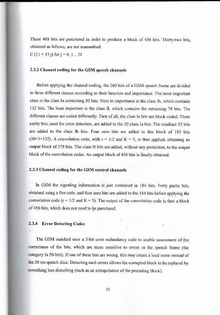
2.3.2 Channel coding for the GSM speech channels
Before applying the channel coding, the 260 bits of a GSM speech frame are divided
in three different classes according to their function and importance. The most important
class is the class Ia containing 50 bits. Next in importance is the class lb, which contains
132 bits. The least important is the class II, which contains the remaining 78 bits. The
different classes are coded differently. First of all, the class Ia bits are block-coded. Three
parity bits, used for error detection, are added to the 50 class Ia bits. The resultant 53 bits
are added to the class lb bits. Four zero bits are added to this block of 185 bits
(50+3+ 132). A convolution code, with r = 1/2 and K = 5, is then applied, obtaining an
output block of 378 bits. The class II bits are added, without any protection, to the output
block of the convolution coder. An output block of 456 bits is finally obtained.
2.3.3 Channel coding for the GSM control channels
In GSM the signaling information is just contained in 184 bits. Forty parity bits,
obtained using a fire code, and four zero bits are added to the 184 bits before applying the
convolution code (r = 1/2 and K = 5). The output of the convolution code is then a block
of 456 bits, which does not need to be punctured.
•2.3.4 Error Detecting Codes •
The GSM standard uses a 3-bit error redundancy code to enable assessment of the
correctness of the bits, which are more sensitive to errors in the speech frame (the
category Ia 50-bits). If one of these bits are wrong, this may create a loud noise instead of
the 20 ms speech slice. Detecting such errors allows the corrupted block to be replaced by
something less disturbing (such as an extrapolation of the preceding block).
20

The polynomial representing the detection code for category Ia bits is:
G(X)=XJ +X+J (2. I)
At the receiving side, the same operation is done and if the remainder differs, an error is
detected and the audio frame is eventually discarded.
2.3.5 Convolution Coding I Decoding
Convolution coding consists in transmitting the results of convolutions of the source
sequence using different convolution formulas. The GSM convolution code consists in
adding 4 bits (set to "O") to the initial 185 bit sequence and then applying two different
convolutions: polynomials are respectively
G 1 (X)=X4 +X3 +J
G 2(X)=X4 +X J +X+J.
(2.2)
(2.3)
Convolution decoding can be performed using a Vitter algorithm .A Vitter decoder
logically explores in parallel every possible user data in sequence. It encodes and
compares each one against the received sequence and picks up the closest match: it is a
maximum likelihood decoder. To reduce the complexity (the number of possible data
sequence double with each additional data bit), the decoder recognizes at each point that
certain sequences cannot belong to the maximum likelihood path and it discards them.
The encoder memory is limited to K bits; a Vitter decoder in steady-state operation keeps•
only 2 K -] paths. Its complexity increases exponentially with the constraint length K.
The GSM convolution coding rate per data flow is 378 bits each 20 ms, i.e.: 18.9
kb/s. However, before modulate this signal, the 78 unprotected Class II bits are added
(see Figure 2.2). So, the GSM bit rate per flow is 456 bits each 20 ms i.e. 22.8 kb/s.
21

Note that there is a software Vitter decoder developed by Phil Kem, from Qualcomm Inc.
which supports the (K=7, r=l/2) NASA standard code.
2.4 Interleaving
Interleaving is meant to de-correlate the relative positions of the bits respectively in
the code words and in the modulated radio bursts. The aim of the interleaving algorithm
is to avoid the risk of loosing consecutive data bits. GSM blocks of full rate speech are
interleaved on 8 bursts: the 456 bits of one block are split into 8 bursts in sub-blocks of
57 bits each. A sub-block is defined as either the odd- or the even-numbered bits of the
coded data within one burst. Each sub-blocks of 57 bits is carried by a different burst and
in a different TDMA frame. So, a burst contains the contribution of two successive
speech blocks A and B. In order to destroy the proximity relations between successive
bits, bits of block A use the even positions inside the burst and bits of block B, the odd
positions (see Figure 2.2).
JJOIJOOIOIOOOIIIOOIO
Blodcitıg I lnterleovlııı I H)I J 000 I I 00 I O I I 00 I O ı
f 1()1100011 0011001010
+fl OIi 00110 000110/010
+I I O I I 0010 I 000 I I I 00 I O
1101100101 OOOlf 10010
•ı ıoı ıoeıo: 0000001010
ıTran.smission I
frtors
ııoııooıoı ER.ROR ErrorCorN<tlon
•Figure 2.2: Interleaving operation
De-interleaving consists in performing the reverse operation. The major drawback of
interleaving is the corresponding delay: transmission time from the first burst to the last
one in a block is equal to 8 TDMA frames (i.e. about 37 ms).
22

Rearrange a group of bits in a particular way. It is used in combination with FEC
codes in order to improve the performance of the error correction mechanisms. The
interleaving decreases the possibility of losing whole bursts during the transmission, by
dispersing the errors. Being the errors less concentrated, it is then easier to correct them.
A burst in GSM transmits two blocks of 57 data bits each. Therefore the 456 bits
corresponding to the output of the channel coder fit into four bursts (4* 114 = 456). The
456 bits are divided into eight blocks of 57 bits. The first block of 57 bits contains the bit
numbers (O, 8, 16 ... 448), the second one the bit numbers (1, 9, 17 .. .449), etc. The last
block of 57 bits will then contain the bit numbers (7, 15 .. .455). The first four blocks of 57
bits are placed in the even-numbered bits of four bursts. The other four blocks of 57 bits
are placed in the odd-numbered bits of the same four bursts. Therefore the interleaving
depth of the GSM interleaving for control channels is four and a new data block starts
every four bursts. The interleave for control channels is called a block rectangular
interleave.
2.4.1 Interleaving for the GSM speech channels
The block of 456 bits, obtained after the channel coding, is then divided in eight
blocks of 57 bits in the same way as it is explained in the previous paragraph. But these
eight blocks of 57 bits are distributed differently. The first four blocks of 57 bits are
placed in the even-numbered bits o.f four consecutive bursts. The other four blocks of 57
bits are placed in the odd-numbered bits of the next four bursts. The interleaving depth of
the GSM interleaving for speech channels is then eight. A new data block also starts
every four bursts. The interleave for speech channels is called a block diagonal
interleave.
23

2.4.2 Interleaving for the GSM data TCH channels
A particular interleaving scheme, with an interleaving depth equal to 22, is applied to
the block of 456 bits obtained after the channel coding. The block is divided into 16
blocks of 24 bits each, 2 blocks of 18 bits each, 2 blocks of 12 bits each and 2 blocks of 6
bits each. It is spread over 22 bursts in the following way :
I-the first and the twenty-second bursts carry one block of 6 bits each
2-the second and the twenty-first bursts carry one block of 12 bits each
3-the third and the twentieth bursts carry one block of 18 bits each
4-from the fourth to the nineteenth burst, a block of 24 bits is placed in each burst
A burst will then carry information from five or six consecutive data blocks. The data
blocks are said to be interleaved diagonally. A new data block starts every four bursts.
2.5 Ciphering I Deciphering
Protection has been introduced in GSM by means of transmission ciphering. The
ciphering method does not depend on the type of data to be transmitted (speech, user data
or signaling) but is only applied to normal bursts.
Ciphering is achieved by performing an '' exclusive or" operation between a pseudo
random bit sequence and 1 14 useful bits of a normal burst (i.e. all information bits except
the 2 stealing flags). The pseudo-random sequence is derived from the burst number and••a key session established previously through signaling means. Deciphering follows
exactly the same operation.•
Ciphering is used to protect signaling and user data. First of all, a ciphering key is
computed using the algorithm A8 stored on the SIM card, the subscriber key and a
random number delivered by the network (this random number is the same as the one
used for the authentication procedure). Secondly, a 114-bit sequence is produced using
the ciphering key, an algorithm called A5 and the burst numbers. This bit sequence is
then XORed with the two 57 bit blocks of data included in a normal burst.
24

In order to decipher correctly, the receiver has to use the same algorithm AS for the
deciphering procedure.
2.6 Modulation
The modulation chosen for the GSM system is the Gaussian Minimum Shift Keying
(GMSK).
The aim of this section is not to describe precisely the GMSK modulation as it is too
long and it implies the presentation of too many mathematical concepts. Therefore, only
brief aspects of the GMSK modulation are presented in this section.
The GMSK modulation has been chosen as a compromise between spectrum
efficiency, complexity and low spurious radiations (that reduce the possibilities of
adjacent channel interference). The GMSK modulation has a rate of 270 5/6 kbauds and a
BT product equal to 0.3. Figure 2.3 presents the principle of a GMSK modulator.
• coswt
[~~ .l_n_ --ı.i Integra ı---. aussi ___. ~ ___.
b.on fılter f _J cos (wt+ f)
jsrnl~-- t sin wt
Figure 2.3: GMSK modulator
GSM uses the Gaussian Modulation Shift Keying (GMSK) with
I-modulation index (deviation ratio) h = Tb (!1 - !2) = 0.5
2-BT (filter bandwidth times bit period) equal to 0.3
3-modulation rate of 271 (270 5/6) kbauds
•
25

The GMSK modulation has been chosen as a compromise between a fairly high
spectrum efficiency (of the order of 1 bit/Hz) and a reasonable demodulation complexity.
The constant envelope allows the use of simple power amplifiers and the low out-of-band
radiation minimizes the effect of adjacent channel interference. GMSK differs from
Minimum Shift Keying (MSK) in that a pre-modulation Gaussian filter is used. The time
domain impulse response of the filter is described in Equation (2.1 ), where
1r k1B -k2s2ı2k J = _/
21n2, and h(t) = J; e 1 and µ=O, therefore
And B is the half-power bandwidth. The Viterbi algorithm can also be used as a
Maximum Likelihood Sequence Estimator (MLSE) equalizer. So a GSM receiver can
contain two different implementations of the Viterbi algorithm.
2. 7 Discontinuous Transmission (DTX)
This is another aspect of GSM that could have been included as one of the
requirements of the GSM speech codec. The function of the DTX is to suspend the radio
transmission during the silence periods. This can become quite interesting if we take into
consideration the fact that a person speaks less than 40 or 50 percent during a
conversation. The DTX helps then to reduce interference between different cells and to
increase the capacity of the system. It also extends the life of a mobile's battery. The
DTX function is performed thanks to two main features:
•1-The Voice Activity Detection (VAD), which has to determine whether the sound
represents speech or noise, even if the background noise is very important. If the voice
signal is considered as noise, the transmitter is turned off producing then, an unpleasant
effect called clipping.
26

2-The comfort noise. An inconvenient of the DTX function is that when the signal is
considered as noise, the transmitter is turned off and therefore, a total silence is heard at
the receiver. This. can be very annoying to the user at the reception because it seems that
the connection is dead. In order to overcome this problem, the receiver creates a
minimum of background noise called comfort noise. The comfort noise eliminates the
impression that the connection is dead.
2.8 Timing Advance
The timing of the bursts transmissions is very important. Mobiles are at different
distances from the base stations. Their delay depends, consequently, on their distance.
The aim of the timing advance is that the signals coming from the different mobile
stations arrive to the base station at the right time. The base station measures the timing
delay of the mobile stations. If the bursts corresponding to a mobile station arrive too late
and overlap with other bursts, the base station tells, this mobile, to advance the
transmission of its bursts.
2.9 Power Control
At the same time the base stations perform the timing measurements, they also
perform measurements on the power level of the different mobile stations. These power
levels are adjusted so that the power is nearly the same for each burst.•• A base station also controls its power level. The mobile station measures the strength
and the quality of the signal between itself and the base station. If the mobile station does• •
not receive correctly the signal, the base station changes its power level.
2.10 Discontinuous Reception
It is a method used to conserve the mobile station's power. The paging channel is
divided into sub channels corresponding to single mobile stations. Each mobile station
27

will then only 'listen' to its sub channel and will stay in the sleep mode during the other
sub channels of the paging channel.
2.11 Multipath and Equalization
At the GSM frequency bands, radio waves reflect from buildings, cars, hills, etc. So
not only the 'right' signal (the output signal of the emitter) is received by an antenna, but
also many reflected signals, which corrupt the information, with different phases.
An equalizer is in charge of extracting the 'right' signal from the received signal. It
estimates the channel impulse response of the GSM system and then constructs an
inverse filter. The receiver knows which training sequence it must wait for. The equalizer
will then, comparing the received training sequence with the training sequence it was
expecting, compute the coefficients of the channel impulse response. In order to extract
the 'right' signal, the received signal is passed through the inverse filter.
2.12GSM Service
It is important to note that all the GSM services were not introduced since the
appearance of GSM but they have been introduced in a regular way. The GSM
Memorandum of Understanding (MoU) defined four classes for the introduction of the
different GSM services:
I-EI : introduced at the start of the service.
2-E2: introduced at the end of 1991.•.
3-Eh: introduced onavailability of half-rate channels.
4-A: these services are optional.
Three categories of services can be distinguished:
• Teleservices.
• Bearer services.
• Supplementary Services.
28

2.12.1 Teleservices
I-Telephony (El® Eh).
2- Facsimile group 3 (El).
3- Emergency calls (EI® Eh).
4-Teletex.
Short Message Services (El, E2, A). Using these services, a message of a maximum
of I 60 alphanumeric characters can be sent to or from a mobile station. If the mobile is
powered off, the message is stored. With the SMS Cell Broadcast (SMS-CB), a message
of a maximum of 93 characters can be broadcast to all mobiles in a certain geographical
area. Fax mail. Thanks to this service, the subscriber can receive fax messages at any fax
machine. Voice mail. This service corresponds to an answering machine.
2.13 Summary
In this chapter I have tried to give and explain about the GSM speech coding, GSM
channel coding and convolution coding /decoding, additionally to give information about
interleaving , modulation and power control.
At the GSM frequency bands, radio waves reflect from buildings, cars, hills, etc. So
not only the 'right' signal (the output signal of the emitter) is received by an antenna, but
also many reflected signals, which corrupt the information, with different phases .
•
29

3. The GSM RADIO INTERFACE
3.1 Introduction ,
The radio interface in GSM uses a combination between frequency (FDMA) and time
(TDMA) multiplexing. The frequency division in GSM 900 allocates 125 frequencies in
each direction for GSM. The uplink (MS to BTS) frequencies are in the area 890 - 915
MHz and the downlink (BTS to MS) frequencies in the are 935-960 MHz. The carrier
frequencies are separated with 200 kHz on each side. The frequencies are allocated in pair,
so that each uplink/downlink pair is separated with exactly 45 MHz. as shown in figure3.1 .
Figure3.1: The synchronization ofTDMA framesı
Each of the carrier frequencies are divided into 8 logical channels, using TDMA. A
TDMA frame contains one time-frame from each of the eight channels, and lasts 4.615 ms.
The time-frames from each channel lasts 0.577 ms.The total bit rate for all 8 channels is
270.833 kbit/s, whereas the bit rate for each channel is 22.8 kbit/s .
30

In order to get the TDMA scheme to work, the time-frames from each mobile station
must be synchronized when received by the BTS. This synchronization is achieved by
using the concept of Timing Advance (TA), defined in . The degree of synchronization is
measured by the BTS on the uplink, by checking the position of the training sequence. This
training sequence is mandatory in all frames transmitted from the MS. From these
measurements, the BTS can calculate the Timing-Advance and send it back to the MS in
the first downlink transmission. From the TA value received from the BTS, the MS know
when to send the frame, so that it can arrive at the BTS in synchronism. The values of the
TA is continuously calculated and transmitted to the MS during the lifetime of a
connection.
The TA can take values from to 233µs. These values are coded by 6 bits, where defines
O to be no timing-advance, and 63 to be the maximum timing advance. This gives a time
difference of 233/63=3.7.
3.2 Frequency Allocation
Two frequency bands, of 25 Mhz each one, have been allocated for the GSM system:
I-The band 890-915 Mhz has been allocated for the uplink direction (transmitting from
the mobile station to the base station).
2-The band 935-960 Mhz has been allocated for the downlink direction (transmitting
from the base station to the mobile station).
But not all the countries can use the whole GSM frequency bands. This is due
principally to military reasons and to the existence of previous analog systems using part of•• the two 25 Mhz frequency bands.
31

3.3 Multiple Access Scheme
The multiple access scheme defines how different simultaneous communications,
between different mobile stations situated in different cells, share the GSM radio spectrum.
A mix of Frequency Division Multiple Access (FDMA) and Time Division Multiple
Access (TDMA), combined with frequency hopping, has been adopted as the multiple
access schemes for GSM.
3.2.1 FDMA and TDMA
Using FDMA, a frequency is assigned to a user. So the larger the number of users in a
FDMA system, the larger the number of available frequencies must be. The limited
available radio spectrum and the fact that a user will not free its assigned frequency until he
does not need it anymore, explain why the number of users in a FDMA system can be
"quickly" limited.
On the other hand, TDMA allows several users to share the same channel. Each of the
users, sharing the common channel, are assigned their own burst within a group of bursts
called a frame. Usually TDMA is used with a FDMA structure.
In GSM, a 25 Mhz frequency band is divided, using a FDMA scheme, into I 24 carrier
frequencies spaced one from each other by a 200 kHz frequency band. Normally a 25 Mhz
frequency and can provide I 25 oarrier frequencies but the first carrier frequency is used as
a guard band between GSM and other services working on lower frequencies .
•Each carrier frequency is then divided in time using a TDMA scheme. This scheme
splits the radio channel, with a width of 200 kHz, into 8 bursts. A burst is the unit of time in
a TDMA system, and it lasts approximately 0.577 ms. A TDMA frame is formed with 8
bursts and lasts, consequently, 4.6 I 5 ms. Each of the eight bursts, that form a TDMA
frame, are then assigned to a single user.
32

3.3 GSM Channel Structure
The GSM standard not only specifies then "when" of different channels in those
different types of information is transmitted in different burst periods, frames, multi-frames
super-frames etc.
It also distinguishes the "why" of the information under the phrase of "logical
channels", For example, it is not sufficient to identify between TCH and CCH. The GSM
standard identifies the different types of CCH and TCH that are used.
Depending on the kind of information transmitted (user data and control signaling), we
refer to different logical channels, which are mapped under physical channels (slots).
Digital speech is sent on a logical channel named TCH, which during the transmission
can be an allocated to a certain physical channel. In a GSM system no RF channel and no
slot is dedicated to a priori to the exclusive use of anything (any RF channel can be used for
number of different uses).
Logical channels are divided into two categories:
i) Traffic Channels (TCHs)
ii) Control Channels.
A channel corresponds to the recurrence of one burst every frame. It is defined by its
frequency and the position of its corresponding burst within a TDMA frame. In GSM there
are two types of channels:
I -The traffic channels used to transport speech and data information .•
2-The control channels used for network management messages and some channel
maintenance tasks, We have already introduced the physical channels used in GSM, namely
8 burst periods per frame on an FDMA carrier.
We have also seen the need for the transmission of two distinct types of information
between MS and BS, namely control (signaling) and user traffic information, This leads to
33

the concept of two types of channels: Traffic Channel (TCH) used to convey user traffic
information, Control Channels (CCH) used to convey signaling information between MS
and network
Typically, burst period O in a frame is used (in both directions) as a CCH, Remaining
seven burst periods in the TDMA are "nominally" TCHs, However, and this simple picture
is not the complete picture.
We have already seen that the normal burst in a burst period which carries TCH can be
"stolen" to carry specific types of "urgent" signalling information, Up to four consecutive
frames can be stolen for this Fast Associated Control Channel (FACCH), For example, the
26 channel multi-frame structure applies to burst periods used as TCH, in this multi-frame
structure, in frames O to 11; the burst period acts as a TCH, In frame 12, it acts as a means
of transmitting specific type of control information (Slow Associated Control Channel -
SACCH). In frames 13 to 24, it again acts as a TCH, in frame 25; it is actually unused to
allow the MS to do other tasks.
Similarly, the 51 frame multi-frame used on burst period carrying certain CCH (e.g.
burst period O) is used in a similarly manner to separate when different "types" of
signalling information (or channels) are transmitted
3.3.1 Traffic Channels (TC)
A traffic channel (TCH) is used to carry speech and data traffic. Traffic channels are
defined using a 26-frame multiform, or group of 26 TDMA frames. The length of a 26-• • frame multiform is 120 ms, which is how the length of a burst period is defined ( 120 ms
divided by 26 frames divided by 8 burst periods per frame). Out of the 26 frames, 24 are
used for traffic, 1 is used for the Slow Associated Control Channel (SACCH) and 1 is
currently unused. TCHs for the uplink and downlink are separated in time by 3 burst
periods, so that the mobile station does not have to transmit and receive simultaneously,
thus simplifying the electronics.
34
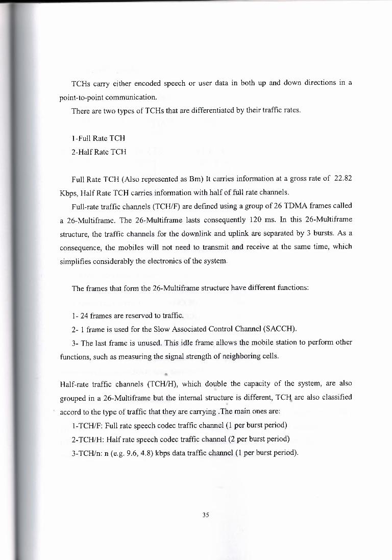
TCHs carry either encoded speech or user data in both up and down directions in a
point-to-point communication.
There are two types of TCHs that are differentiated by their traffic rates.
1-Full Rate TCH
2-Half Rate TCH
Full Rate TCH (Also represented as Bm) It carries information at a gross rate of 22.82
Kbps, Half Rate TCH carries information with half of full rate channels.
Full-rate traffic channels (TCH/F) are defined using a group of 26 TDMA frames called
a 26-Multiframe. The 26-Multiframe lasts consequently 120 ms. In this 26-Multiframe
structure, the traffic channels for the downlink and uplink are separated by 3 bursts. As a
consequence, the mobiles will not need to transmit and receive at the same time, which
simplifies considerably the electronics of the system.
The frames that form the 26-Multiframe structure have different functions:
1- 24 frames are reserved to traffic.
2- 1 frame is used for the Slow Associated Control Channel (SACCH).
3- The last frame is unused. This idle frame allows the mobile station to perform other
functions, such as measuring the signal strength of neighboring cells.
Half-rate traffic channels (TCH/H), which double the capacity of the system, are also
grouped in a 26-Multiframe but the internal structure is different, TC!i. are also classified. · accord to the type of traffic that they are carrying .The main ones are:
1-TCH/F: Full rate speech codec traffic channel ( 1 per burst period)
2-TCH/H: Half rate speech codec traffic channel (2 per burst period)
3-TCH/n: n (e.g. 9.6, 4.8) kbps data traffic channel (1 per burst period).
35

3.3.2 Control Channels
Basic structure of Control channel
Figure 3.2. Basic structure of Control channel
Actually in the above diagram S will be at slot 1 of next frame, F is frequency
correction channel, which occurs every 10th burst. The next frame to S contains service
operator's information. There are four important different classes of control channels
defined:
I-Broadcast Channels (BCH)
2-Comınon Control Channels (CCCH)
3-Dedicated Control Channels (DCCH)
4-Associated Control Channels (ACCH)
Each class is further subdivided to identify specific "logical channels",
The mapping of these "logical" channels onto "physical" channels is quite complex but
some examples have already been mentioned
• Broadcast Channels •• ••
Which gives to the mobile station the training sequence needed in order to demodulate
the information transmitted by the base station, Broadcast channels are transmitted by the
base station to convey "information" to ALL MS in the cell Three different "logical" BCH
exist information necessary for the MS to register in the system.
36

I - The Broadcast Control Channel (BCCH)
Which gives to the mobile station the parameters needed in order to identify and access
the network? BCCH is a point-to-multipoint unidirectional control channel from the fixed
subsystem to MS that is intended to broadcast a variety of information to MSs, BCCH has
5 I bursts. BCCH is dedicated to slot I and repeats after every 5 I bursts.
Broadcast Control Channel (BCCH) continually broadcasts, on the downlink,
information including base station identity, frequency allocations, and frequency hopping
sequences. This provides general information per BTS basis (cell specific information)
including information necessary for the MS to register at the system. After initially
accessing the mobile, the BS calculates the requires MS power level and sets a set of power
commands on these channels. Other information sent over these channels includes country
code network code, local code, PLMN code, RF channels used with in the cell where the
mobile is located, and surrounding cells, hopping sequence number, mobile RF channel
number for allocation, cell selection parameters, and RACH description. One of the
important messages on a BCCH channel is CCCH_CONF, which indicates the organization
of the CCCHs. This channel is used to down link point-to-multipoint communication and is
unidirectional; there is no corresponding uplink. The signal strength is continuously
measured by all mobiles which may seek a hand over from its present cell and thus it is
always transmitted on designated RF channel using time slot O(zero). This channel is never
kept idle-either the relevant messages are sent or a dummy burst is sent.
2- Frequency correction channel (FCCH)••The Frequency-Correction Channel (FCCH), which supplies the mobile station with
the frequency reference of the system in order to synchronize it with the uetwork (FCCH) is
· used to allow an MS to accurately tune to a BS. The FCCH carries information for the
frequency correction of MS downlink. It is required for the correct operation of radio
system. This is also a point-to multipoint communication. This allows an MS to accurately
tune to a BS. ) conveys all information required by the MS to access and identify the
network - transmitted in burst period O on only one (non-hopping) carrier in a cell The
BCCH is a point-to-multipoint unidirectional control channel from the fixed subsystem to
37

MS that is intended to broadcast a variety of information to MSs, including information
necessary for the MS to register in the system. BCCH has 51 bursts. BCCH is dedicated to
slot 1 and repeats after every 51 bursts.
3- Synchronization channel (SCH)
Which gives to the mobile station the training sequence needed in order to demodulate
the information transmitted by the base station (SCH) is used to provide TDMA frame
oriented synchronization data to a MS. When a mobile recovers both FCCH and SCH
signals, the synchronization is said to be complete. SCH repeats for every 51 frames. SCH
carries information for the frame synchronization (TDMA frame number of the MS, and the
identification of BTS). This is also required for the correct operation of the mobile.
The Synchronization Channel contains 2 encoded parameters:
1-BTS identifications code (BSIC)
2- Reduced TDMA frame number (RFN).
• Common Control Channels (CCCH)
A CCCH is a point-to-multipoint (bi-directional control channel) channel that is
primarily intended to carry signaling information necessary for access management
functions (e.g., allocation of dedicated control channels). The CCCH channels help to
establish the calls from the mobile station or the network. Three different types of CCCH
can be defined:
The CCCH includes:
1- Paging channel (PCH)
Which is used to search (page) the MS in the downlink direction, The Paging Channel
(PCH). It is used to alert the mobile station of an incoming cal
2- Random access channel (RACH)
The Random Access Channel (RACH), which is used by the mobile station to request
access to the network which is used by MS to request of an SDCCH either as a page
response from MS or call origination/ registration from the MS. This is uplink channel and
38

operates in point-point mode (MS to BTS).This uses slotted ALOHA protocol. This causes
a possibility of contention. If the mobiles request through this channel is not answered with
in a specified time the MS assumes that a collision has occurred and repeats the request.
Mobile must allow a random delay before re-initiating the request to avoid repeated
collision. It is used by MS when it attempts to request access to the network
3- Access grant channel (AGCH)Which is a downlink channel used to assign a MS to a specific SDCCH or a TCH.
AGCH operates in point-to-point mode. A combined paging and access grant channel is
designated as PAGCH. The Access Grant Channel (AGCH). It is used, by the base station,
to inform the mobile station about which channel it should use. This channel is the answer
of a base station to a RACH from the mobile station _Access Grant Channel (AGCH) is
used by BS to tell MS which DCH to use after it has sent a message over the RACH
• Dedicated Control Channels (DCCH)
The Standalone Dedicated Control Channels (SDCCH) are allocated to specific
mobiles to exchange information with the network for a specific duration
A typical use of the SDCCH would be to exchange signalling relating to a call set up.
A DCCH is a point-to-point, directional control channel. The DCCH channels are used
for message exchange between several mobiles or a mobile and the network. Two different
types of DCCH can be defined:
Two types of DCCHs used at,e:
1- Standalone DCCH (SDCCH)Is used for system signaling during idle periods and call setup before allocating a TCH,• ••
for example MS registration, authentication and location updates through this channel.
When a TCH is assigned to MS this channel is released. Its data rate is one-eighth of the
full rate speech channel which is achieved by transmitting data over the channel once every
eighth frame. The channel is used for uplink and downlink and is meant for point-to-point
39

usage, it is used in order to exchange signaling information in the downlink and uplink
directions.
2- The slow associated control channels (SACCH)
Is data channel carrying information such as measurement· reports from the mobile of
received signal strength for a serving cell as well as the adjacent cells, This is necessary
channel for the assisted over hand over function, is also used for power regulation of MS
and time alignment and is meant for uplink and down link. It is used for point-to-point
communication. SACCH can be linked to TCH or an SDCCH.
• Associated Control Channels
Two types of ACH, which have already been mentioned:
I-Slow ACH (SACCH) which is transmitted in the TCH burst period once every TCH
multi-frame and is used for signalling of a non-urgent nature relating to the call ( e.g.
supplementary service and call related requests)
2-Fast ACH (FACCH) which is formed by "stealing" up to four consecutive TCH
bursts (frames) to convey "urgent" signalling information (e.g. handover, power control,
timing advance) The Fast Associated Control Channels (FACCH) replace all or part of a
traffic channel when urgent signaling information must be transmitted. The FACCH
channels carry the same information as the SDCCH channels.
It is a DCCH whose allocation is linked to the allocation of a CCH. A FACCH or burst
stealing is a DCCH obtained by pre-emptive dynamic multiplexing on a TCH.•
A FACCH is also associated to TCH. FACCH works in a stealing mode. This means
that if suddenly during a speech transmission it is necessary to exchange signaling
information with the system at a rate much higher than the SACCH can handle, then 20 ms
speech (data) bursts are stolen for signaling purposes. This is the case at the case at the
40

hand over. The user will not hear the interruption of the speech since it lasts only for 20 ms
and cannot sensed by human ears.
3.4 Structure of TDMA Slot with a Frame
There are five different kinds of bursts in the GSM system. They are:
I-Normal Burst
2-· Synchronization Burst
3-Frequency Correction Burst
4- Access Burst
5- Dummy Burst
3.4.1 Normal Burst
This burst is used to carry information on the TCH and on control channels. The lowest
bit number is transmitted first. The encrypted bits are 57 bits of data or (speech + 1 bit
stealing flag) indicating whether the burst was stolen for FACCH signaling or not. The
reason why the training sequence is placed in the middle is that the channel is constantly
changing. By having it there, the chances are better that the channel is not too different
when it affects the training sequence compared to when the information bits were affected.
If the training sequence is put at the beginning of the burst, the channel model that is
created might not be valid for the bits at the end of a burst there are 8 training sequences
shown at the diagram. The 26 bits equalization patterns are determined at the time of the
call setup.
"'
41

3.4.2 Synchronization Burst
ı '"IDMA rraırne(4.615 ms)
l tiınesloo; (0.577 ms:)
Leg.en.cl: TB = "Tail Bit-;f:= FlagGB = Guard band
Figure 3.3. GSM TDMA structure and normal burst number of bits per field below the
field legend
This burst is used for the time synchronization of the mobile. It contains 64 bit
synchronization sequence. The encrypted 78 bits carry information of the TDMA frame
number along with the BSIC. It is broadcast together with the correction burst. The TDMA
frame is broadcast over SCH, in order to protect the user information against
eavesdropping, which is accomplished is ciphering the information before transmitting. The
algorithm that calculates the ciphering key uses a TDMA frame number as one of the
parameters and therefore, every frame must have a frame number. By knowing the TDMA
frame number, the mobile will know what kind of logical channel is being transmitted on
the control channel TSO. BSIC is also used by the mobile to check the identity of the BTS
when making signal strength measurements (to prevent measurements on co-channel cells).
3.4.3 Frequency Correction Burst•
This burst is used for frequency synchronization of the mobile. It is equivalent to an un
modulated channel with a specific frequency offset. The repetition of these bursts are called
FCCH.
42

3.4.4 Access Burst
This burst is used for random access and longer GP to protect for burst transmission
from a mobile that does not know the timing advance when it must access the system. This
allows for a distance of 35 km from base to mobile. Incase the mobile is far away from the
BTS, theinitial burst will arrive late since there is no timing advance on the first burst. The
delay must be shorter to prevent it from overlapping a burst in the adjacent time-slot
following this.
3.4.5 Dummy Burst
It is sent from BTS on some occasions as discussed previously which carrıes no
information and has the format same as the normal burst. The normal burst is used to carry
speech or data information. It lasts approximately 0.577 ms and has a length of I 56.25 bits.
Its structure is presented in figure 3.4.
Furnn 0-11: TCH Fnm< 12: SAC CH Fxarnn 13-24: TCH F:nı:n.e2:5 : Unused
O I 1 I 2 I 3 I 41SI'517 I 8 I 9 llOllll12l13ll4llSl1'5l17l18ll9l20l21l22l23l24l2S
26-f:urn.r mul t.if:r;ırn.rDu:nt.ion: 120 rn.:s
BP4
TDMAfxanuDU.J";ıtion:60/13 ms
- - - ----I 3 I S7 I 1 I 2'5 I 1 ITail D;ıubit.s Sual in& T:ninin.ı: sualin&bit.:s bit. sırqU,,ll!n.ce bit.
S7 0 a.zs
Daubiu Tail G~:rdbits bit.s
No:rnul be.astDUJ:at.ion 1:5126[1'\3
Figure 3.4: Structure of the 26-Multiframe, the TDMA frame and the normal burst•
This figure has been taken, with the corresponding authorization, from "An Overview
of GSM" by John Scoria's.
The tail bits (T) are a group of three bits set to zero and placed at the beginning and the end
of a burst. They are used to cover the periods of ramping up and down of the mobile's
power.
43

The coded data bits correspond to two groups, of 57 bits each, containing signaling or
user data. The stealing flags (S) indicate, to the receiver, whether the information carried by
a burst corresponds to traffic or signaling data. The training sequence has a length of 26
bits. It is used to synchronize the receiver with the incoming information, avoiding then the
negative effects produced by a multipath propagation. The guard period (GP), with a length
of 8.25 bits, is used to avoid a possible overlap of two mobiles during the ramping time.
3.5 Frequency Hopping
The propagation conditions and therefore the multipath fading depend on the radio
frequency. In order to avoid important differences in the quality of the channels, the slow
frequency hopping is introduced. The slow frequency hopping changes the frequency with
every TDMA frame. A fast frequency hopping changes the frequency many times per
frame but it is not used in GSM. The frequency hopping also reduces the effects of cochannel interference.
There are different types of frequency hopping algorithms. The algorithm selected is
sent through the Broadcast Control Channels, Even if frequency hopping can be very useful
for the system, a base station does not have to support it necessarily On the other hand, a
mobile station has to accept frequency hopping when a base station decides to use it.
3.6 Summary•
••In this chapter I tried to explain and give information about GSM radio interface and
the meaning of radio interface also channel structure , frequency allocation and TDMN
FDMA structure . We have also seen the need for the transmission of two distinct types of
information between MS and BS, namely control (signaling) and user traffic information.
44

The radio interface in GSM uses a combination between frequency (FDMA) and time
(TDMA) multiplexing. The frequency division in GSM 900 allocates 125 frequencies in
each direction for GSM. The uplink (MS to BTS) frequencies are in the area 890 - 915
MHz and the downlink (BTS to MS) frequencies in the are 935-960 MHz .
•
45

4. LEVELS of RADIO FRECUENCY RADIATION FROM
GSM MOBILE TELEPHONE BASE STATION
4.1 Introduction
In recent years there has been a proliferation of base station towers designed to meet
increased demands placed on mobile telephone networks by the growing number of
mobile phone users .In parallel with the construction of these base station towers there
has been an increase in community concern about possible health effects from the radio
frequency (RF) radiation emissions from the towers. The Australian Government
Committee on Electromagnetic Energy (EME) Public Health Issues (CEMEPHI), as
part of the public information component of its RF EME program, considers it
important that the general public be informed about the RF EME levels to which they
may be exposed. Accordingly, the CEMEPHI requested the Australian Radiation
Protection and Nuclear Safety Agency (ARPANSA) to carry out a survey of the RF
EME levels in the vicinity of mobile telephone base stations. This report provides
information on the levels of RF radiation from RF transmitter towers (base stations) to
which members of the public may be exposed. Reviews on the potential health risks of
RF radiation are available elsewhere (e.g., UNEP/WHO/IRPA, 1993; Barnett, 1994;
McKinley etal, 1996; ICNIRP, 1998; Repacholi, 1998; Byrus et al., 1999).
Both at indoor and outdoor sites, yielded power density measurements well within
Canada's safety code limits (Safety Code 6, 1990). Signal sources investigated in the
Thansandote et al survey included base station frequency bands for analog cellular
phones and personal communication services (PCS - the new generation of digital
cellular phone), as well as AM radio, FM radio and TV broadcasts. A US study by
Petersen and Testagrossa (1992) characterized RF EME fields in the vicinity of several
frequency modulated (FM) cellular radio antennae towers, at heights varying from 46 to
82 meters. They reported maximum power densities considered representative of public
exposure levels to be less than 0.0001 W/m 2 per transmitter. Hence, in a worst-case
scenario of 96 transmitters operating at an effective radiated power (ERP) of 100 watts
per transmitter; the aggregate maximum power density was estimated by Petersen and
46

Testagrossa to be below O.Ol W/m 2. In Poland, where the maximum permissible power
density value is 0.1 WIm 2 at relevant base station.
Frequencies, measurements of electromagnetic fields (EMF) in the surrounds of 20
GSM base stations showed that 'admissible EMF intensities at the level of people's
presence, in existing buildings, in surroundings of base stations and inside buildings
with antennas, were not exceeded' (Aniolczyk, I 999, p.57).
The purpose of the work reported here is to provide data on RF EME levels at
independently nominated sites, over the range of the digital Global System for Mobile
communication (GSM) mobile telephone base stations frequency band (935 - 960
MHz), and to make comparisons with the limit for non-occupational exposure specified
ın the relevant Australian exposure standard. The Radio communications
(Electromagnetic Radiation Human Exposure) Standard 1999 adopted by the Australian
Communications Authority (ACA) requires mobile phones and mobile phone base
stations to comply with the exposure limits in the interim Australian and New Zealand
Standard 2772.1(Int): 1998 which has now been withdrawn by
Standards Australia. The ACA standard is subsequently abbreviated as ACAS in this
publication. The non-occupational exposure limit specified in the ACAS, expressed in
terms of power flux density, is 2 W/m2 (equivalent to 200 µW/cm2) for frequencies
between I O MHz and 300 GHz, averaged over a 6 minute period. It should be noted that
the exposure limits in the ACAS were 'developed on the basis of there being a threshold
of 4 W/kg whole body specific absorption rate (SAR) before any adverse health••consequences are likely to appear' (ibid, p.13). However, because the SAR (units W/kg)
is difficult and often impractical to measure, the ACAS provides. derived levels of•
• electric (E) and magnetic (H) field strengths, as well as the equivalent plane wave power
flux densities (S), which are more readily measured.
Although the primary focus of the ARPANSA study was to measure the RF EME
emission levels from GSM base stations, fixed site environmental measurements from
other RF EME sources were also recorded, including the analog mobile phone system
(AMPS), VHF TV UHF TV, AM radio, FM radio and Paging.
47

4.2 Method of Measurement Locations
Measurements were performed at fourteen different locations throughout 1
Two localities were chosen from each state, and the Northern Territory.
instances the sites were chosen by local governments, who were asked to nom:
mobile telephone base stations sites in major population centers that were of cc
local communities. Security of monitoring equipment for the 24-hour dau
component was taken into account in the final selection of the measuremı
Following the nature and type of the measurements required.
4.2.1 Fixed Site Environmental Measurements
Broadcast communication sources such as television, and both AM radio
radio, are usually transmitted at high powers from a single base facility. Suet
have very extensive areas of effective reception frequently extending to many 1
of kilometers from a single station transmitter. Furthermore, for such sou
considering their necessary broadcast design requirements, we do not e:
encounter significant or strong variations in signal strength in relatively op
surrounding a mobile telephone base station. Given the nature and ernphasi
study we therefore adopted a protocol of making a single set of static envirc
measurements for all broadcast sources other than mobile telephone base station
Buildings or other likely objects may significantly attenuate or scatter the R
Hence, where possible, measurements were made in locations that maintaine
line-of-sight with known RF sources, at a height of 1. 7 meters above ground,
areas in the near vicinity of the GSM base station of interest. Measurement ı
were oriented to obtain maximum signal strength for the particular frequency ba
Being measured. The environmental RF EME signals were measured at a
within 500 meters of the base station.
Measurement of such fixed site environmental RF EME levels i
investigating a number of different RF EME sources. These included GS~,
48

VHF TV, UHF TV, AM radio, FM radio and paging. All signals with power densities
greater than I% of the observed maximum for each frequency band were recorded
individually. Other signals, such as emergency services (police, ambulance, etc.) and
taxis, were rarely detected and are not included in this summary report. To measure the
environmental RF EME levels the average RF EME levels over a six minute scanning
period during the day was determined. The time taken to record all the relevant sources
of environmental RF EME at each site was approximately one hour. A spectrum
analyzer was used and some transient signal sources,
Such as paging services, may have gone undetected if by chance the relevant
frequency band was not swept by the spectrum analyzer when the signal was
transmitted.
4.2.2 GSM Base Station Activity Measurements
The primary aim of this study was to determine the RF EME level resulting from all
signal frequencies produced by the particular GSM base stations under survey. Mobile
telephone communication signals are both transient and partly random in their
occurrence and distribution. In this context, we were interested in determining the RF
EME levels at many locations and more particularly, we wanted to estimate both
maximum and minimum levels and also the long term average value for each location
and to map such levels in the area surrounding the base station. Because telephonecommunications are based on htıman activity,
A diurnal signal pattern is generally observed- Site-specific GSM mobile telephone
exposure levels were therefore monitored over a 24-hour period. Relevant spectrum
analyzer data were recorded automatically under PC control and subsequently analyzed
to determine both the temporal and daily average activity. Measurements were
performed within a single sector, at a fixed location close to the base station, by
continuously scanning the frequency bands and logging the signal level for the GSM
mobile phone systems. The recorded data were used to determine the temporal activityfor the GSM systems over the 24-hour period.
49

The activity level of the data samples was determined by counting the number of
simultaneous active time slots for a single carrier base station. For the majority of GSM
base stations there is a possible minimum of eight and a possible maximum of thirty
two time slots for any given sector.
Hence, eight time slots will amount to 25% of the total activity possible from the
transmitting antenna of a single carrier GSM base station.
The digital GSM base stations produce carrier frequencies between 935 to 960 MHz
(analog AMPS system operates at 870 to 890 MHz). The GSM system transmits data in
bursts of 0.6µsec with a repetition rate of 217 Hz. The temporal RF EME levels of the
transmitting antennae at GSM base stations were analyzed to identify control
frequencies or additional carrier frequencies. For GSM the frequency range investigated
was divided up into three sub-bands, with the sampling order of each sub-band and
frequency randomized to avoid bias. The system was optimized to gather as much data
as possible by sampling more often when fewer frequencies were detected. Post logging
data analysis was performed to determine the average activity over a six-minute
scanning period, yielding an activity value for every six minutes of the day. The
analysis software included only the signals identified as belonging to the base station in
question. Where more than one carrier (Telstra, Optus or Vodafone) shared the same
tower, the combined activity from all carriers was determined. A diurnal correction
factor was derived from analysis of the 24-hour activity measurements for use in mobile
measurements.
4.2.3 Mobile GSM Base Station Area Measurements •
A fixed antenna was roof mounted on a car and automated mobile measurements
were made whilst driving around the streets near the GSM base station under survey.
Both signal data and position information [using Global Positioning System (GPS)]
were recorded. For technical reasons, we were not able to make simultaneous
measurements of all frequencies at each particular mobile measurement sample location.
However, for each base station sector there is always a single "control frequency"
present and this frequency is produced at a constant transmitter power. The control
50

frequency is broadcast from the same antennae as additional transient earner
frequencies. In addition, the control frequency will have similar propagation
characteristics to those of any additional frequencies. Hence, to determine the RF EME
area levels, only the control frequency (surrogate for all frequencies) was measured.
Application of the diurnal correction factor obtained by previous activity data analysis
yielded an estimate of the average RF EME over 24 hours at each measured point in the
mappıng area.
Maps of each survey area displaying the distribution of the 24-hour average RF
EME levels at each measured point are presented in the individual reports for each
survey site.
4.2.4 Equipment
All RF EME measurements were recorded using a portable Tektronix Model 2712
Spectrum Analyzer. This instrument is essentially a radio receiver with the capacity to
measure the power distribution of a received signal as a function of frequency. Signal
amplitude was usually measured in dB relative to a mill watt (dBm). Calculation of field
strength requires knowledge of the receiving antenna properties and system losses.
Because the dBm measurements were all recorded in the far field of the transmitting
antennae, the measurements results could be converted to equivalent electric field
strength in dB relative to microvolt per meter (dBµ V/m) using the following equation:
Field strength (dBµV/m) = dBm measurement+ 107 + receiving antenna factor+••cable loss factor + spectrum analyzer calibration factor
•The field strength values (in dBµ V/m) were subsequently converted to power flux
density. Power flux density (S) is commonly expressed in units of microwatt per square
centimeter (µW/cm 2) and, in the far field of a transmitting antenna, can be calculated
from the plane wave relationship:
E2 = Z*S (4.1)
Where E is the electric field strength (units V/m) and Z is the characteristic
Impedance of free space (377ohms).
51

The spectrum analyzer was interfaced to and controlled, via a communication card,
by a portable laptop computer based data logging system utilizing a portable GPS
receiver. The receiver was operated in differential mode.
GSM and AMPS power density measurements were recorded from the signals
radiated by the mobile telephone base stations. The signals measured by the spectrum
analyzer, over the frequency ranges specified below, were received using a variety of
antennae. Each receiving antenna was calibrated at relevant frequencies, and the
calibration factors were used in the calculations of the RF EME levels. The overall
uncertainty of the measurement results is estimated to be ± 6dB. The following
receiving antennae were used:
1- Low frequency signals (AM radio); O.Ol MHz - 30 MHz loop antenna; EMCO
model 6502 active loop. This antenna was used for the stationary environmental
measurements;
2-Very High Frequencies (FM radio, VHF TV, paging); 20 MHz - 320 MHz bi
conical antenna; A.H. Systems model SAS 200/541. This antenna was used for the
stationary environmental measurements.
3-Ultra High Frequency (UHF TV, mobile telephone, paging); 300 MHz - I 000
MHz log periodic antenna; A.H. Systems model SAS 200/51O. This antenna was used in
the environmental and base station activity measurements; and Mobile phone
frequencies; 870 MHz - 960 MHz magnetic base vehicle roof mount antenna; supplied
by Telstra Shop. This antenna ~as used to determine 24-hour base station activity levels
and mobile area survey measurements.
•
4.3 Results for RF EME Exposure and Activity Levels from GSM Base Stations
Table below lists the RF EME power flux density (µW/cm 2) and activity levels for
the GSM base stations at the 13 relevant locations. The reference to RF EME levels
always implies power flux density levels (µW/cm 2 ). When comparing the RF EME
power flux density levels with that of the ACAS, the comparison will be given as, for
example, "the limit specified in the ACAS is at least X times greater than this level." At
52

,/
··~ 1988 • ,..<l<the bottom of Table 2 the mean and SD are given, as well as the number of sites (N~
where measurements were made. No activity levels were measured from any single
GSM base station in Leichhardt, and so no measurements for Leichhardt were reported
in Table 2. Also, for technical reasons the activity Levels at Bulleen were only recorded
over a I 2-hour period, between late morning and late evening.
The RF EME measurements at each locality were each adjusted to represent the
mean RF EME level for the 24-hour recording period at each particular measurement
position. Column 2 in Table 2 gives the 'highest average' RF EME levels (i.e., the
highest of all the 24 hour mean RF EME readings in the surveyed area), whilst Column
3 lists the 'area average' RF EME levels (i.e., the average of all the 24 hour mean RF
EME readings in the surveyed area).
The surveyed area at each site was restricted to a radius of a few kilometers from the
GSM base station. For illustrations of the spatial variation in the 24-hour mean RF EME
measurements at a particular site refer to the survey map of the report for that locality.
Column 4, Column 5 and Column 6 in Table 2 lists the minimum, maximum and
average activity levels respectively over a 24hour period. These activity levels were
obtained by recording the telephone activity of the GSM base station over a 24hour
period from one position. Figure I illustrates the overall changes in activity at each
measurement locality. The three symbols in the graph correspond to the minimum
activity, average activity and maximum activity over the 24-hour period. The full names
for the locality abbreviations given in Figure I are as follows: Bulleen (Bul), Bunbury
(Bun), South Melbourne (SMe), Repatriation Hospital (Rep), Rapid Creek (Rap),
Palmerston (Pal), Nerang (Ner), Launceston (Lau), Kenmore (Ken), Jolimont (Joi),
· Hobart (Hob), Fulham (Ful) and Engadine (Eng). For graphs displaying the temporal
variation in activity over the 24-hour period at each individual site refer to the specific
report for that locality.
Across all GSM base stations the average of the 24 hour variation in telephone
activity was 32% of the total available capacity (a factor of I .27 compared with the
minimum operational capacity of 25%), with the maximum base station activity
averaging 48% of the total available capacity. The largest change possible is an increase
53

by a factor of four, which occurs when four transmitters are operating at full power.
Bulleen, Vic. had the largest measured variation in activity. For this site there was a
change in activity of 40% with respect to the total available capacity (a factor of 2.6
compared with the minimum operational capacity of 25%).
The smallest variation in activity was at Bunbury and Fulham, where no change in
activity over the 24-hour period was recorded (i.e., it remained at 25% capacity).
WOI ,.........--~~--
o rntnıı1uım acuvı~901 I 'v over age activityo rnilximuın .ıcthtily
~() -~ '10-..•.o ~·,,.. .,,
f'''iC'O
!;..#)
60 I lQ. I lf i~~l I~ 1(.) I çı rı I I I- 50 I r 'r I I o I I~ I r I l ~~'l I r:l ı,,~u, ,ıo t f
I I CJ I I r ı 't-- I l I ·ı t fo I ' t I I I?J. 30 I r i ! t I i Id) o d, d) d) d) t\ d>
20 -I I I r I I I I I I r l ·y II I r I I I I I I r I I I
ıo -I I I r I I I I I I r I I II I I I I I I I I r I I II I r I I I I I I r I I I
ol I I ı ı I I ı I I ı J IBul Bun SMo Rop Rop Pat NGtr UUJ Kon ):(';! Hob Ful l::ng
Locality Figure4.1: Activity levels of GSM Base Station.
I
The changes in activity of GSM base stations over a 24-hour period are illustrated.
The full names for the locality abbreviations are given in the text.
Column 7 in Table 2 shows what the RF EME levels at maximum activity were at
the point in the surveyed area that yielded the 'highest average' reading. Column 8 lists
what the RF EME levels would be at the point in the surveyed area that yielded the
'highest average' reading if the base station operated at full (100%) capacity. Figure 2
displays graphically the GSM RF EME levels for the different activity levels at the 13
54

locations of measurement. As illustrated in Figure 2 the 'area average' RF EME levels
were considerably less than the 'highest average' RF EME levels at most sites. The
largest of the 'highest average' RF EME levels was at Kenmore (0.052 µW/cm 2- the
limit specified in the ACAS is at least 3,000 times greater than this level), as was the
largest of the 'area average' RF EME levels (0.0051 µW/cm2 - the limit specified in
the ACAS is at least 30,000 times greater than this level). At maximum activity the
largest RF EME occurred at Kenmore (0.082 µW/cm2 - the limit specified in the
ACAS is at least 2,000 times greater than this level), whilst at 100% activity the largest
RF EME was at Nerang (0.178 µW/cm 2 - the limit specified in the ACAS is 1,000
times greater than this level). The mean of the 'highest average' RF EME levels over all
sites was 0.020 µW/cm2 (the limit specified in the ACAS is 10,000 times greater than
this level).
The mean of the 'area average' RF EME levels over all sites was 0.0016 µW/cm2
(the limit specified in the ACAS is at least 100,000 times greater than this level). For
maximum and 100% activity the means were 0.031 µW/cm2 (the limit specified in the
ACAS is at least 6,000 times greater than this level) and 0.062 µW/cm 2 (the limit
specified in the ACAS is at least 3,000 times greater than this level) respectively.
Figure 4.2: RF power flux density levels (µW/cm2) for GSM Base Station
55

The above 3D plot is of the GSM base stations RF EME power flux density levels
for thel3 different locations, at different activity levels.
4.4 Summary
In the last chapter in my project Ü contains information about Results for RF EME.
Exposure and Activity Levels from GSM Base Stations, Mobile GSM Base Station
Area Measurements and Method of Measurement Locations .
In recent years there has been a proliferation of base station towers designed to meet
increased demands placed on mobile telephone networks by the growing number of
mobile phone users .In parallel with the construction of these base station towers there
has been an increase in community concern about possible health effects from the radio
frequency (RF) radiation emissions from the towers.
•
56

CONCLUSION
The developers of GSM chose digital system, as opposed to the standard analog
cellular systems like AMPS in the United States and TACS in the United Kingdom. They
had faith that advancements in compression algorithms and digital signal processors
would allow the fulfillment of the original criteria and the continual improvement of the
system in terms of quality and cost. GSM was designed to be compatible with ISDN
servıces.
Protection has been introduced in GSM by means of transmission ciphering. The
ciphering method does not depend on the type of data to be transmitted ( speech, user data
or signaling) but is only applied to normal bursts; Ciphering is used to protect signaling
and user data. The EIR is also used for security purposes. It is a register containing
information about the mobile equipments. More particularly, it contains a list of all valid
terminals.
One of the main objectives of GSM is roaming. Therefore, in order to obtain a
complete compatibility between mobile stations and networks of different manufacturers
and operators, the radio interface must be completely defined. The specification of the
radio interface has then an important influence on the spectrum efficiency. Not all the
countries can use the whole GSM frequency bands. This is due principally to military
reasons and to the existence of previous analog systems using part of the two 25 MHz
frequency bands.
All information must be provided on the "levels of RF radiation from RF
transmitter towers (base stations) to which members of the public may be exposed.
Reviews on the potential health risks of RF radiation are available elsewhere.
57

REFERENCE [1] Mamedov, Fakhereddin, Telecommunication Lecture Note (2000)
[2]. Cheung et al., "Network Planning for Third-Generation Mobile Radio Systems,"
IEEE Communications Magazine 32, no. 11 (Xovember 1994): 54-69.
[3]. Chia, "Beyond the Second-Generation Mobile Radio Systems, "British Telecom
Engineering 1 O (January 1992): 326-335.
[4]. Cox, D. C., "Personal Communicarions-A Viewpoint,"IEEE Communication
Magazine (November 1990): 8-20.
[5]. European Telecommunications Stan
for G5M900/DC51800" (ETSI, Cedex, r irution (ETSI i, "Recommendations
[6]. Gardiner. J. D. "Second Generation C
and the Common Air Interface," IEE Electrczics
Journal (April 1992).
elephony in U.K: Telepoint Services
and Communications Engineering
[7]. Gilhousen, K. S., et al., "On the Capz..:i~~ of a Cellular CDMA system."IEEE
transaction on Velzicular technology VT-40, :....,..'.? {~fay 1991 ): 303-12.
[8]. Goodman, D. J., "Trends in Cellular -.~ Cordless Communications;' IEEE
Communications Magazine (Jane 1991 ): 31-~"-
[9]. Grillo and Macnamee, "European P
Communication Systems," Proceedings of
May 1990.
on Third Generation Personal
C Conference. Orlando, Florida.