Embed Size (px)
Citation preview

NEAR EAST UNIVERSITY
Witricity (Wireless Power Transmission)
A Thesis Presented To the Faculty
of Electrical & Electronic Engineering
Near East University, Nicosia, TRNC
In Partial Fulfillment of the
Requirements for the Degree of
4th year Senior Project (EE400)
Prepared By:
Mouhamed Aghiad Raslan
Mohammad Dadoua
Supervised By: Assoc. Prof. Dr. Özgür C. Özerdem
June 2015

II
This page was left blank on purpose
©2015
ALL RIGHTS RESERVED

III
DEDICATION
بسم هللا الرحمن الرحيم
نسان علم بالقلم علم الذي الكرم وربك اقرأ " "يعلم لم ما ال
To the source of light in our lives…
To whom always take care of us…
To greatest creator… “هللا عز وجل”
To every one cherish…
To the one who enlightened our lives with the light of faith…
To the one who enlightened our lives with the light of knowledge…
To our guide in life… صلى هللا عليه وسلم النبي محمد
To the people who are the source of love, happiness, kindness and safety in our lives…
To the people who were always there for us… To the ones who stood by our side when
no one else was there…
To the people who saw the best in us, and gave us the best they can to see us growing up
and reach the place we are in now…
To who took care of us and gave us moral support and strength when we were weak…
Our fathers Our mothers and Our families
To the people who helped us throughout our study and through our work on this project,
to the people who support us in every possible way to see this work succeed to our
friends.

IV
ACKNOWLEDGMENT
We won’t forget the people who worked so hard to be helpful guides for us, our Doctors,
Teachers and supporters who have been so generous to help us along the way.
We are very grateful for the project supervisors because without their valuable efforts and
continuous guidance, this project could not have been completed;
Assoc. Prof. Dr. Özgür C. Özerdem
Eng. Mohammed Kmail, M.Sc
We would like to express our gratitude and thanks to everyone who helped and supported
us in this course of this project. First we would like to thank the university
administration, faculty Dean; Prof. Dr. Ali Ünal ŞORMAN, and our colleagues at NEU
for their helpful and constructive participation.
Special Thanks to:
Google.com (since it was the most useful thing throughout the work).
Eng. Mohammed Kmail, M.Sc

V
Index
Abstract ...........................................................................................................................................1
Chapter 1: Introduction to WiTricity ..........................................................................................2
1.1 What is WiTricity? .................................................................................................................3
1.2 Why do we need WiTricity? ..................................................................................................4
1.3 What can we do with WiTricity? ...........................................................................................5
1.4 How does WiTricity work? ....................................................................................................5
Chapter 2: History of WiTricity ...................................................................................................6
2.1 Nicola Tesla ............................................................................................................................6
2.2 Tesla Contribution ..................................................................................................................6
Chapter 3: How to WiTricity? ......................................................................................................9
3.1 Wireless energy transmission technology ..............................................................................9
3.2 Wireless Power Transmission Experiments .........................................................................11
3.2.1 Microwave-Based Experiment ................................................................................................... 11
3.2.2 LASER-Based Experiment ........................................................................................................ 11
3.3 LASER Power Transmission ..............................................................................................13
3.3.1 LASER Selection ....................................................................................................................... 14
a. Standard Indirectly Pumped LASERs ........................................................................................ 15
b. Direct Solar Pumped LASERs ................................................................................................... 16
3.3.2 Recent and Ongoing Research ................................................................................................... 17
3.3.3 Other Application on LASER-Based Wireless Power Transmission ........................................ 21
a. Planetary and lunar surface applications .......................................................................21
b. Powering tether “climbers” for a space elevator ............................................................22
c. Wireless power driven propulsion .................................................................................22

VI
3.4 Highly Resonant Wireless Power Transmission .................................................................22
3.4.1 System Description .................................................................................................................... 22
3.4.2 Physics of Highly Resonant Wireless Power Transfer .............................................................. 25
a. Resonance .................................................................................................................................. 25
b. Coupled resonators..................................................................................................................... 26
3.4.3 Technology Benefits .................................................................................................................. 29
a. Consumer Electronics ................................................................................................................ 31
b. Medical Devices......................................................................................................................... 32
c. Electrical Vehicles ..................................................................................................................... 33
d. LED Lighting ............................................................................................................................. 33
e. Defense Systems ........................................................................................................................ 34
Chapter 4: Practical Application of WiTricity .........................................................................36
4.1 Components ..........................................................................................................................36
4.2 Concept of Working .............................................................................................................36
4.3 Steps .....................................................................................................................................37
4.4 Building the Receiver ...........................................................................................................37
4.5 Results ..................................................................................................................................38
4.5.1 Test 1.......................................................................................................................................... 38
4.5.2 Test 2.......................................................................................................................................... 38
Chapter 5: Human Safety ...........................................................................................................41
5.1 Tissue Heating ......................................................................................................................42
5.2 Nerve and Muscle Stimulation .............................................................................................44
5.3 Electromagnetic simulations ................................................................................................45
5.4 Human body models .............................................................................................................46
Appendix A ...................................................................................................................................49

VII
Appendix B ...................................................................................................................................57
References .....................................................................................................................................59

1
Abstract
We cannot imagine the world without electric power. Generally the power is
transmitted through wires. This project describes an original idea to eradicate the hazardous
usage of electrical wires which involve lot of confusion in particularly organizing them.
Imagine a future in which wireless power transfer is feasible: cell phones, household robots,
mp3 players, laptop computers and other portable electronics capable of charging themselves
without ever being plugged in, freeing us from that final, ubiquitous power wire. Some of these
devices might not even need their bulky batteries to operate. This project includes the
techniques of transmitting power without using wires with an efficiency of about 95% with
non-radiative methods. Due to which it does not affect the environment surrounding. These
techniques Includes resonating inductive coupling in sustainable moderate range. The coupling
consists of an inductor along with a capacitor with its own resonating frequency. In any system
of coupled resonators there often exists a so-called “strongly coupled” regime of operation. If
one ensures to operate in that regime in a given system, the energy transfer can be very efficient.
Another technique includes transfer of power through microwaves using rectennas. This is
particularly suitable for long range distances ranging kilometers. With this we can avoid the
confusion and danger of having long, hazardous and tangled wiring. This project as a whole
gives an effective, high performance techniques which can efficiently transmit the power to the
required area varying in distances. .

2
Chapter 1 Introduction to WiTricity
High power moving objects can be supplied economically if appropriate wireless power
transfer (WiTricity) sources exist. A maglev system, with a linear synchronous motor, for
instance, requires primary windings distributed along the track, resulting in substantial increase
in the construction and maintenance cost. Placing windings on the mover plus a proper
WiTricity system considerably reduces the cost. A suitable structure for high power WiTricity
systems should be designed to satisfy the best performance and meet the requirement of the
application. The simplicity of the implementation is also essential in selecting the WiTricity
structure.
In WiTricity for high power moving applications, the apparatus usually includes a small
air gap along the main flux path that links two coils. A primary coil is located on the stationary
base unit while a secondary coil is located on the vehicle. The latter coil effectively receives
the power from the primary side through the air gap and delivers it to the vehicle. The power
can be used immediately by a traction motors or can be stored for later use. Also, a WiTricity
structure can be constructed in conjunction with a magnetic levitation system using Hallbach
arrays, permanent magnets (PMs), passive and self-controlled systems. Although the required
power for a levitation system is usually lower than the power needed by a propulsion system,
the combined system causes a reduction in total weight of vehicle and improves its
performance.
Different WiTricity structures for transferring high power form long primary tracks to
moving objects are considered. In particular, two types of WiTricity systems, i.e., with long
bus bars and with long magnetic material cores are proposed. Also, WiTricity structures for
monorail systems with U, S, E, Z and λ shapes are introduced. Two WiTricity structures are
presented and analyzed for the linear servo motors. A WiTricity system consisting of a U shape
pickup on the vehicle and three wires as primary winding is proposed for supplying movable
vehicles. The mentioned works not thoroughly discuss the system analysis and design,
considering practical limitations such as operating frequency when both high power transfer
and high efficiency are desirable. In order to attain high performances in WiTricity systems,
capacitive compensations in both primary and secondary sides are recommended to provide
resonance conditions. Resonance based WiTricity systems save weight, space and cost of the
system. However, some special applications can be supplied by non-resonance based WiTricity
systems with proper designs.

3
Coaxial WiTricity systems including a straight primary wire passing through the center of
a cylindrical secondary core with an air gap have already been recognized. It can be used in
Maglev as well as in wireless EV charging systems and power delivery system for mining
applications. Also, a high power coaxial inductive power transfer pickup is presented. A partial
design of the system is reported recently. However, a systematic modeling, analysis and design
procedure is not reported in the literature.
In this work, a coaxial WiTricity system as in Fig. 1 is considered. A mathematical model
is used for the system analysis including the compensating capacitors. The analysis includes
the calculation of transferred power, efficiency, coupling coefficient, etc.. Then, a design
procedure is proposed to achieve high efficiency and high transferred power. The work extends
the application of low power resonance based inductive magnetic coupling to high power
applications like Maglev. The system parameters are obtained to meet the design specifications.
Analytical results are verified by 3D FEM simulations to confirm the design.
1.1 What is WiTricity?
WiTricity (wireless power transmission) is nothing but wireless electricity.
Transmission of electrical energy from one object to another without the use of wires is called
as WiTricity. WiTricity will ensure that the cell phones, laptops, iPods and other power hungry
devices get charged on their own, eliminating the need of plugging them in. WiTricity
technology is transferring electric energy or power over distance without wires. With the basics
4
of electricity and magnetism, and work our way up to the WiTricity technology. Even better,
because of WiTricity some of the devices won't enquire batteries to operate. No, this concept
of wireless electricity is not new. In fact it dates back to the 19th century, when Nikola
Tesla used conduction- based systems instead of resonance magnetic fields to transfer
wireless power. Further, in 2005, Dave Gerding coined the term WiTricity which is
being used by the MIT researchers today. Moreover, we all are aware of the use of
electromagnetic radiation (radio waves) which is quite well known for wireless transfer
of information. In addition, lasers have also been used to transmit energy without wires.
However, radio waves are not feasible for power transmissions because the nature of the
radiation is such that it spreads across the place, resulting into a large amount of radiations
being wasted. And in the case of lasers, apart from requirement of uninterrupted line of
sight (obstacles hinders the transmission process), it is also very dangerous.
1.2 Why do we need WiTricity?
There are so many places where a power source is needed for many appliances to work,
but batteries cannot be there. Examples of such situations include remote underwater locations
for temperature and tide sensors, concrete reinforcements for corrosion detectors, or even
inside our own body for diagnostic endoscopes, etc. In such instances, ability to deliver power
wirelessly where it is needed becomes an enabler to a much larger impact from countless
electrical devices. Wireless Power Transmission (WiTricity) is the transmission of electrical
energy from a power source to an electrical load without a conductive physical connection or
interconnecting wires. Transmission of power wirelessly is very different from data
communication wirelessly. Radio waves are used to send and receive cell phone, TV, radio,
and WiFi data. The radio waves spread in all directions until they reach the antenna that is
tuned to the right frequency. Spreading power in a similar way would be not only inefficient
but also dangerous. Therefore, WiTricity is done utilizing technologies like inductive coupling.
WiTricity is increasingly being used to make everyday products like cell phones, laptop
computers, mobile robots, and electric vehicles, capable of re-charging themselves without
ever being plugged in. WiTricity enables flat screen TVs hang on the wall without any wires
to power source. Medical devices and implants no longer need wires or batteries. Pacemakers
do not have to be surgically replenished with batteries every few years. WT technologies
5
continue to evolve, so they can be safely and efficiently over larger and larger distances and
deliver large amount of power.
1.3 What Can We Do with WiTricity?
Wireless energy transmission applications by WiTricity technologies will enable a new
tether less truly mobile connected world:
Eliminate cords for everything from lamps and laptops to kitchen appliances
Eliminate the need for surgery to replace batteries for pacemakers inside human
bodies
Eliminate chargers for mobile cell phone and cameras chargers
Eliminate extra installations needed for new power outlets when installing electrical
devices
Eliminate restrictions of distance and need to place electrical product within a limited
cord range to the wall outlet
Eliminate dangers of tripping posed by dangling power cord
Electrically powered devices will no longer need recharging
Highways would continuously recharge electric cars that drive on them
1.4 How Does WiTricity Work?
Wireless energy transfer (WiTricity) is an emerging technology that can wirelessly provide
perpetual energy supply to wireless networks and wireless devices. WET is achieved by either
the “near-field” electromagnetic (EM) induction technology or the “far-field” EM radiation
(such as radio) for short- or long-range applications, respectively. There are many ways to
transfer low levels of energy including:
WiTricity using EM induction
WiTricity using EM induction with resonance
WiTricity using EM radiation with radio waves
WiTricity using EM radiation with Light Amplification by Stimulated Emission of
Radiation (laser)

6
Chapter 2 History of WiTricity
2.1 Nikola Tesla
Nikola Tesla (Serbian Cyrillic: Никола Тесла; 10 July 1856 – 7 January 1943) was a
Serbian American inventor, electrical engineer, mechanical engineer, physicist, and futurist
best known for his contributions to the design of the modern alternating current (AC) electricity
supply system.
Tesla gained experience in telephony and electrical engineering before immigrating to
the United States in 1884 to work for Thomas Edison in New York City. He soon struck out
on his own with financial backers, setting up laboratories and companies to develop a range of
electrical devices. His patented AC induction motor and transformer were licensed by George
Westinghouse, who also hired Tesla for a short time as a consultant. His work in the formative
years of electric power development was involved in a corporate alternating current/direct
current "War of Currents" as well as various patent battles. Tesla went on to pursue his ideas
of wireless lighting and electricity distribution in his high-voltage, high-frequency power
experiments in New York and Colorado Springs and made early (1893) pronouncements on
the possibility of wireless communication with his devices. He tried to put these ideas to
practical use in his ill-fated attempt at intercontinental wireless transmission, which was his
unfinished Wardenclyffe Tower project. In his lab he also conducted a range of experiments
with mechanical oscillators/generators, electrical discharge tubes, and early X-ray imaging. He
also built a wireless controlled boat, one of the first ever exhibited.
2.2 Tesla contribution
The idea of transmitting power through the air has been around for over a century, with
Nikola Tesla’s pioneering ideas and experiments perhaps being the most well-known early
attempts to do so. He had a vision of wirelessly distributing power over large distances using
the earth’s ionosphere. Most approaches to wireless power transfer use an electromagnetic
(EM) field of some frequency as the means by which the energy is sent. At the high frequency

7
end of the spectrum are optical techniques that use lasers to send power via a collimated beam
of light to a remote detector where the received photons are converted to electrical energy.
Efficient transmission over large distances is possible with this approach; however,
complicated pointing and tracking mechanisms are needed to maintain proper alignment
between moving transmitters and/or receivers. In addition, objects that get between the
transmitter and receiver can block the beam, interrupting the power transmission and,
depending on the power level, possibly causing harm. At microwave frequencies, a similar
approach can be used to efficiently transmit power over large distances using the radiated EM
field from appropriate antennas. However, similar caveats about safety and system complexity
apply for these radiative approaches.
It is also possible to transmit power using non-radiative fields. As an example, the
operation of a transformer can be considered a form of wireless power transfer since it uses the
principle of magnetic induction to transfer energy from a primary coil to a secondary coil
without a direct electrical connection. Inductive chargers, such as those found commonly in
electric toothbrushes, operate on this same principle. However, for these systems to operate
efficiently, the primary coil (source) and secondary coil (device) must be located in close
proximity and carefully positioned with respect to one another. From a technical point of view,
this means the magnetic coupling between the source and device coils must be large for proper
operation.
But what about going over somewhat larger distances or having more freedom in
positioning the source and device relative to each other? That’s the question that a group at the
Massachusetts Institute of Technology asked themselves. They explored many techniques for
transmitting power over “mid-range” distances and arrived at a non-radiative approach that
uses resonance to enhance the efficiency of the energy transfer (see Physics of Highly Resonant
Power Transfer for details). High quality factor resonators enable efficient energy transfer at
lower coupling rates, i.e., at greater distances and/or with more positional freedom than is
otherwise possible (and therefore, this approach is sometimes referred to as “highly resonant”
wireless energy transfer or “highly resonant” wireless power transfer (HR-WiTricity)). The
MIT team demonstrated the highly resonant technique using a magnetic field to transfer energy
over a mid-range distance of 2 meters, and an industry was born. In some instances, this
technology is also referred to as “magnetic resonance”, and it is often contrasted to “induction”
for its ability to efficiently transfer power over a range of distances and with positional and

8
orientational offsets. Since that initial demonstration, the use of HR-WiTricity, or magnetic
resonance, has enabled efficient wireless energy transfer in a wide range of applications that
was not possible before.

9
Chapter 3 How to WiTricity
3.1 Wireless energy transmission technology
In general, effective wireless energy transmission concepts need to comply with a range of
fundamental constraints:
• possibility to transfer the energy though an atmosphere; transparency of the atmosphere
to the used wavelength;
• possibility for directional emission;
• possibility to convert the energy from the form of its source (solar, electric, heat) to a
transmittable form (e.g. microwave, laser, acoustic);
• Possibility to convert the transmittable energy form back into a useful form of energy
(e.g. electricity, hydrogen).
It is useful to compare its performances and parameters with microwave energy
transmission with LASER energy transmission, the most widely studied wireless energy
transmission technology. In principle, laser energy transmission systems are very similar to
energy transmission via microwave technology: the power source (solar, electricity) is
converted into an emitter or an emitter array that generates the directional electromagnetic
radiation, which is subsequently absorbed in a receiver, which transforms the energy back into
a more useful, transportable form, e.g. electricity, heat, hydrogen.
The key difference, the wavelengths used, implies the major other differences between the
laser and microwave-based concepts: While most wireless power transmission rely on
microwave frequencies of either 2.45 or 5.8 GHz (0.12-0.05 m; both in the industrial, scientific
and medical (ISM) frequency band), laser energy transmission takes advantage of the
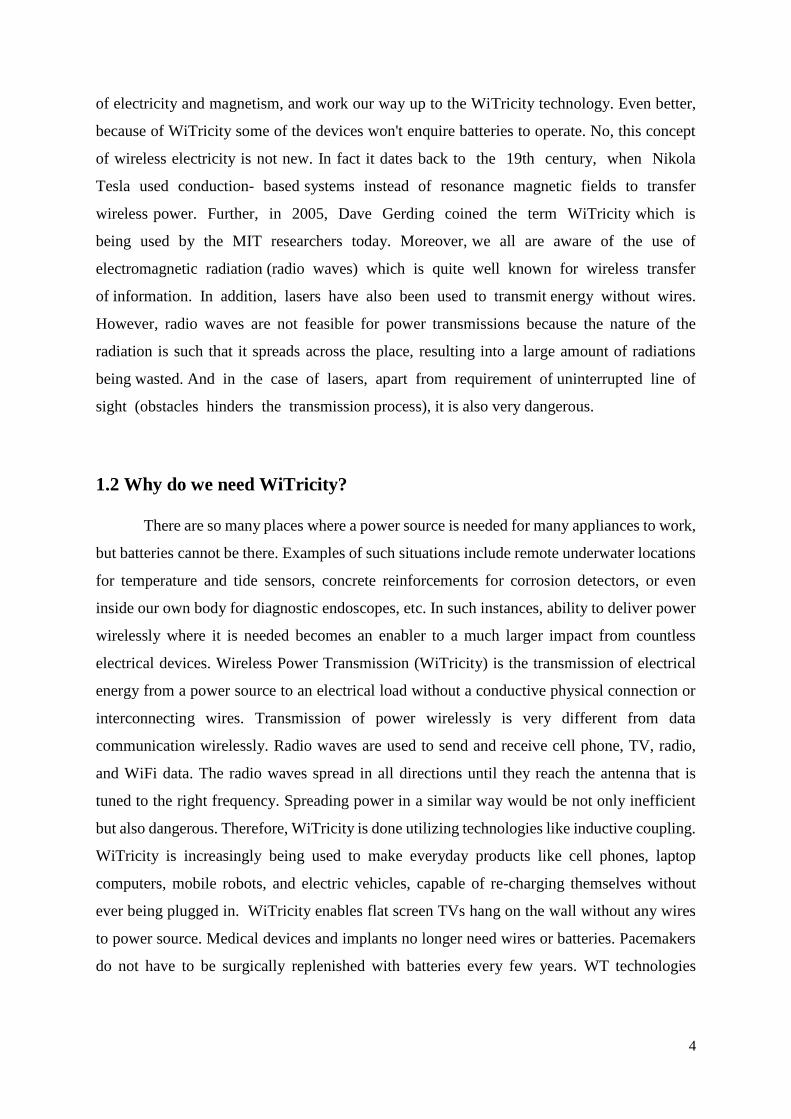
atmospheric transparency window in the visible or near infrared frequency spectrum. (Fig. 1)
10
Figure 3: Transmission and absorption in Earth atmosphere. (Source: NASA)
The five orders of magnitude frequency difference determine the sizing of the emitters
and receiving devices as well as the energy density of the transmission beam according to
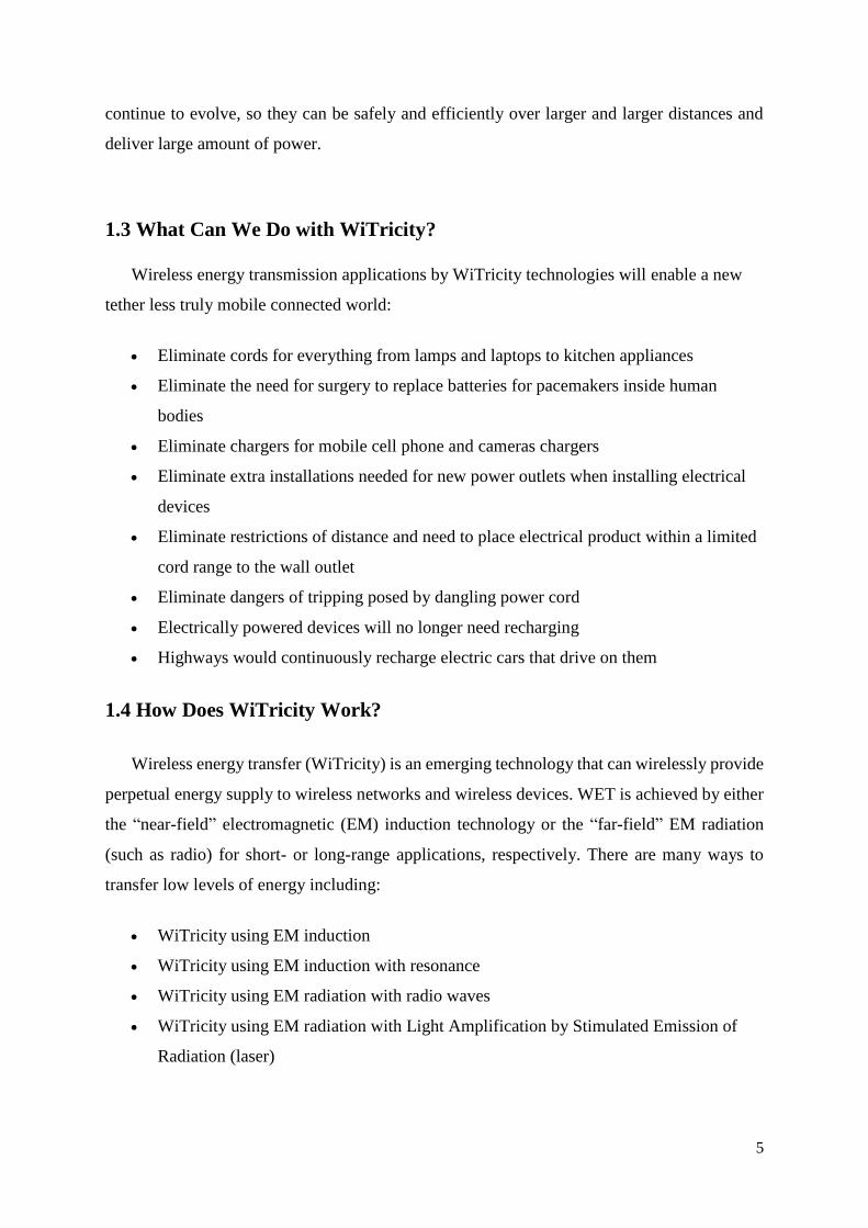
standard optics principles. Similar to the higher data rate achievable with optical data links
(Fig. 2), laser energy transmission allows much higher energy densities, a narrower focus of
the beam and smaller emission and receiver diameters.
Figure 4: Classification of satellite communication systems by beam divergence and data
rate.

11
3.2 Wireless power transmission experiments
The principles of wireless power transmission as considered for SPS and other
applications has already been demonstrated for both technologies: RF and laser systems.
3.2.1 Microwave-based experiments
Microwave-based experiments have demonstrated so far the possibility to supply power
to e.g. helicopters, balloon-based platforms, experimental airplanes, experimental cars, rovers
and cell phones. The first experiment was conducted by W. Brown in 1964, when also the
first “rectenna” and invented and used.
The longest distances between emitting and receiving points achieved so far is in the
order to hundred kilometers. The largest amount of energy transmitted so far was during an
experiment by the US Jet Propulsion Laboratory in 1975, when 30 kW were transmitted from
a 26 m diameter parabolic dish to a 1.54 km distant rectenna with 85% efficiency.
The first energy transmission in space between two objects was achieved by N. Kaya
et al. in 1983. The first airplane powered by a ground based microwave emitter was launched
in Canada in 1987 with the aim to test a wireless power transmission technology to be used
for powering high altitude, quasistationary platforms. Similar experiments were performed in
Japan in 1993 and 1995, powering from the ground a small airplane and a balloon
respectively. The electronic beam steering by phase control of a microwave beam from space
to Earth using a pilot signal has been demonstrated in a sounding rocket experiment in 2006
by Kaya et al.
In a completely different power range and for completely different applications, also
the power supply to RFID chips are to be considered an application of wireless power
transmission by microwaves. Furthermore, these generally use the same ISM frequency band.
3.2.2 Laser-based experiments
While over the years, several laser-based wireless power transmission experiments and
applications have been suggested and described, only relatively few actual experiments have
been carried out compared to the number and diversity of microwave-based experiments
described in the previous section.

12
Classified experiments involving laser power transmission technology demonstration
have been reported to have taken place in the 1980s during the US Strategic Defence
Initiative. These seem to have been conducted building on a heritage from the Apollo
programme that used ground-based lasers with reflectors on the Moon to measure the Earth-
Moon distance. Once of the observatories involved has been the Air Force Maui Optical
Station (AMOS) located on top of mount Haleaki in Hawaii, US. The SDI concepts would
use ground based eximer lasers with adaptive optics and a roughly 5 m mirror in GEO and
another mirror in a polar orbit at roughly 1000 km altitude.
In 2002 and 2003, Steinsiek and Schafer demon-¨ started ground to ground wireless
power transmission via laser to a small, otherwise fully independent rover vehicle equipped
with photovoltaic cells as a first step towards the use of this technology for powering airships
and further in the future lunar surface rovers. The experiment was based on a green,
frequency-doubled Nd:YAG laser at only a few Watts. It included the initiation and supply of
the rover including a micro-camera as payload as well as the pointing and tracking of the
moving rover over a distance up to 280 m by applying active control loops. (Fig. 3)
Recently, similar experiments, however focusing less on the beam control and beam
steering aspects but rather on the total transmitted power levels have been carried out in the
frame of a context related to space elevators, organized and co-funded by NASA. Ground-
based lasers have been used to power small PV-covered “climbers” attached to a tether with
the objective to achieve maximum climbing speeds.
One of the advantages of microwave power transmission over the use of laser has been
the possibility to avoid moving parts in space by using an electronic beam steering system
based on the control of the phase of a matrix of emitters. Recently, Schafer¨ and Kaya have
however demonstrated that a similar system is in principle also possible for laser based
systems by presenting a new concept for a retro directive tracking system.
In the proposed concept, the power transmitter utilizes a receiver’s pilot signal to obtain
information about its direction by conjugating the signal’s phase inside a nonlinear medium.
The emitted power therefore transmitted back to the direction of the receiver by the phase-
conjugated signal beam. In this way, power can be concentrated by an array of phase
conjugators, which offer the possibility to provide a large aperture in order to increase the
intensity at the receiver’s photovoltaic panels. The control of the phase and the direction of

13
the readout beams provides control over the interference pattern, its position, and its size,
offering new possibilities for the design of space based power stations.
Figure 5: EADS developed, fully laser powered autonomous rover. (source: EADS)
3.3 Laser power transmission
Lasers generate phase-coherent electromagnetic radiation at optical and infrared
frequencies from external energy sources by preferentially pumping excited states of a
“lasant” to create an inversion in the normal distribution of energy states. Photons of specific
frequency emitted by stimulated emission enter and are amplified as standing waves in a
resonant optical cavity. The most efficient DC-to-laser converters are solid-state laser diodes
commercially employed in fiber optic and free-space laser communication. Alternatively,
direct solar-pumping laser generation has a major advantage over conventional solid state or
gas lasers, which rely on the use of electrical energy to generate laser oscillation since the
generation of electricity in space implies automatically a system level efficiency loss of
roughly 60%. To generate a laser beam by direct solar pumping, solar energy needs to be
concentrated before being injected into the laser medium. The required concentration ratio is
14
dependent on the size of the laser medium, the energy absorption ratio and the thermal shock
parameter (weakness of the material to internal stress caused by a thermal gradient).
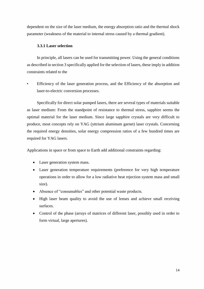
3.3.1 Laser selection
In principle, all lasers can be used for transmitting power. Using the general conditions
as described in section 3 specifically applied for the selection of lasers, these imply in addition
constraints related to the
• Efficiency of the laser generation process, and the Efficiency of the absorption and
laser-to-electric conversion processes.
Specifically for direct solar pumped lasers, there are several types of materials suitable
as laser medium: From the standpoint of resistance to thermal stress, sapphire seems the
optimal material for the laser medium. Since large sapphire crystals are very difficult to
produce, most concepts rely on YAG (yttrium aluminum garnet) laser crystals. Concerning
the required energy densities, solar energy compression ratios of a few hundred times are
required for YAG lasers.
Applications in space or from space to Earth add additional constraints regarding:
Laser generation system mass.
Laser generation temperature requirements (preference for very high temperature
operations in order to allow for a low radiative heat rejection system mass and small
size).
Absence of “consumables” and other potential waste products.
High laser beam quality to avoid the use of lenses and achieve small receiving
surfaces.
Control of the phase (arrays of matrices of different laser, possibly used in order to
form virtual, large apertures).
15
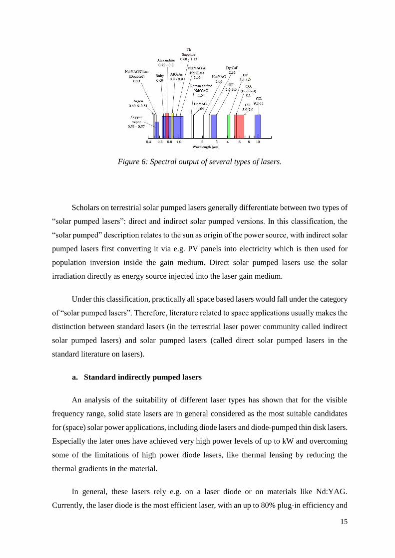
Figure 6: Spectral output of several types of lasers.
Scholars on terrestrial solar pumped lasers generally differentiate between two types of
“solar pumped lasers”: direct and indirect solar pumped versions. In this classification, the
“solar pumped” description relates to the sun as origin of the power source, with indirect solar
pumped lasers first converting it via e.g. PV panels into electricity which is then used for
population inversion inside the gain medium. Direct solar pumped lasers use the solar
irradiation directly as energy source injected into the laser gain medium.
Under this classification, practically all space based lasers would fall under the category
of “solar pumped lasers”. Therefore, literature related to space applications usually makes the
distinction between standard lasers (in the terrestrial laser power community called indirect
solar pumped lasers) and solar pumped lasers (called direct solar pumped lasers in the
standard literature on lasers).
a. Standard indirectly pumped lasers
An analysis of the suitability of different laser types has shown that for the visible
frequency range, solid state lasers are in general considered as the most suitable candidates
for (space) solar power applications, including diode lasers and diode-pumped thin disk lasers.
Especially the later ones have achieved very high power levels of up to kW and overcoming
some of the limitations of high power diode lasers, like thermal lensing by reducing the
thermal gradients in the material.
In general, these lasers rely e.g. on a laser diode or on materials like Nd:YAG.
Currently, the laser diode is the most efficient laser, with an up to 80% plug-in efficiency and

16
an emitted wavelength in the range of 795-850 nm. The most important development effort
seems to be made for diodes emitting in the range of 950 nm (pumping of 1.55 µm fiber laser).
For larger scale space applications for wireless power transmission, large area emitting system
with thousands of individual diodes could be realized. In this case, the main limitation is the
thermal control of such diode panels to maintain optical coherence.
Most of the solid state lasers are based on crystal technology (Nd: YAG, Nd:Y2O3,
Ruby, etc). These lasers are optically pumped in the visible range. The Nd:YAG laser (1.064
µm) is the most widely used; it can be efficiently pumped by laser diodes or solar radiation,
emitting visible radiation at 0.532 µm. The overall system efficiency for the laser diode
pumped concept is reported at about 15%.
b. Direct solar pumped lasers
Direct pumping uses sunlight as the source of the pumping light in order to generate the
laser beam. In order to achieve the required power densities for the inversion process, sunlight
at 1 a.u. needs to be concentrated from its natural 1387 W/m2 to concentration values between
200 and a few thousands depending on the lasing medium. In order to avoid very large
collecting and concentrating surfaces (reflectors or lenses), direct solar pumped lasers add
additional constraints to the selection process described above:
• Low energy densities for the population inversion in order to allow for practically
achievable solar energy concentration ratios;
• High temperature lasing rods able to be combined in series;
• Highly efficient hear removal systems.
The laser rods can be made of a variety of materials; many recent studies have focused
on using semiconductor materials. The power output of direct solar pumped lasers depends
fundamentally on the overlapping between the standard solar emission spectrum and the laser
absorption one. The speculated slope efficiency of this type of pumping is up to 2-3%. The
components of this system are a solar collector, laser medium and on the receiving end either
photovoltaic panels or a heat-based conversion system for the conversion of the laser beam
back to electricity. Alternatively, as for standard lasers, lasers in the infrared wavelength
region might be used to via further concentrations to directly generate hydrogen via the
molecular dissociation process.

17
One of the most critical technical challenges is the design of an efficient heat removal
system from the laser medium. Even with the reported very high conversion efficiencies only
part of the injected solar energy will appear as laser output. The remaining energy will
generate heat. This energy increases the internal energy of the laser medium but does not
appear as laser output. It is therefore important to design the system so that those parts of the
solar spectrum that do not contribute to the laser output are filtered and don’t reach the laser
medium in the first place. One options could be polymer films with a wavelength-dependent
reflectance ratio.
Direct solar pumped lasers present some considerable advantages for space applications,
making this technology in principle more attractive for use in space than on Earth:
Since in space, the energy for laser pumping needs to come from solar radiation the
efficiency of the photovoltaic solar to electric conversion system needs to be included
in a laser technology system analysis. Space PV system efficiencies in the order of 30
to possibly 40% are assumed to be achievable within the next 5 years. Therefore 15%
efficient direct solar pumped lasers would compete with laser systems with a 50%
laser generation efficiency, not accounting for other aspects.
The elimination of the intermediate conversion process from solar into electricity in
space, which eliminates the need for most of the electronics. Eliminating the electricity
intermediate step also solves one of the potentially limiting factors of “traditional”
solar power satellite concepts, namely problems due to high voltages (e.g. arching,).
A fiber laser with optimized sun collector could be an interesting alternative, but only a
very small number of theoretical studies have been carried out to date and it is difficult to
currently quantify the application of this technique for direct solar pumped lasers.
3.3.2 Recent and ongoing research
Most of the very early solar power satellite systems were based on microwave power
transmission. But since the very early phases, laser power transmission was considered as an
alternative. Studies included already in the late 1970s laser based SPS, their economic
rationale, their integration into a hydrogen economy and their potential interactions between
high power laser beams and the environment, including the investigation of potential

18
mitigation techniques to minimize the environment effect by a judicious choice of laser
operating parameters.
The use of laser based wireless power transmission was revisited in the early 1990s by
Landis. Since several years, the Japanese space agency JAXA is pursuing a solid and targeted
R&D program towards the development of space based solar power stations, including as the
two main technical options the microwave and laser based concepts. New designs and laser
system options have been proposed.
The JAXA proposed laser based system is based on direct solar pumped lasers using a
Nd:YAG crystal. A reference system has been designed, delivering in its full configuration 1
GW. The entire system would be built in a highly modular way, with individual modules of
(100 m×200 m) primary mirrors and an equally large radiator system as base unit delivering
10 MW each and stacked to a total length of 10 km in orbit. (Fig. 5 and Fig. 6)
In 2004, JAXA and the Osaka based Institute for Laser Technology have reported an
experiment with direct solar pumped laser beam (using simulated solar light and a fiber laser
medium made from a neodymium-chrome doped YAG (Nd-Cr:YAG) crystal and disc type
bulk crystal) with conversion efficiencies from the input power to the output laser power with
37%.

19
Figure 7: JAXA L-SPS 100x200 m reference unit
delivering 10 MW via direct solar pumped lasers.
(Source: JAXA)
Figure 8: JAXA L-SPS fully deployed reference
system delivering 1 GW via direct solar pumped
lasers. (Source: JAXA)
Figure 9: JAXA L-SPS system diagram. (Source: JAXA)

20
In Europe, the European Space Agency (ESA) has federated European research
communities and industry in 2002 into the European SPS Network. A multiphase program plan
provided the frame for several studies related to laser based SPS.
As part of the first phase, together with EADS Atrium the use of laser power
transmission for space to space applications were studied, including powering surface elements
on the Moon and Mars, Earth orbiting satellites and deep space missions. The lunar surface
application has been identified as the most promising application.
The relatively conservative and compact design incorporated four parallel laser
systems, connected to a 1.5 m diameter telescope capable of emitting 6 kW power. The lasers
are based on solid state diode pumped technology. In order to allow the system in lunar orbit
to provide power to small lunar surface elements, the system design required a pointing
accuracy of only 86.2 nard. Going into some details on the overall system aspects, a rover
acquisition process had been defined, which would reply on a small laser beacon or corner cube
implemented on the rover and receiver optics on the orbiting SPS. Each telescope would have
to be actively controlled to achieve fine pointing accuracy. The rover(s) receiver surface is to
be equipped with wavelength optimized solar PV cells. The spot size dimensions at rover level
measure 14.4 m in diameter and would thus be substantially larger than the rover receiver area,
but on the other hand assure sufficient power during moving of the rover and margins on the
pointing accuracy. The total power the rover was estimated to receive from such a system was
approximately 650 W.
A satellite would be located in Earth-Moon Lagrange point L1-L2 at a distance of about
58,000 km. The system could provide a permanent illumination of any spot of roughly half the
moon. The system would use four Nd-YAG lasers, each with a 10 kW rating and a 1 m diameter
telescope. The SPS would include one power system, one deployable radiator (about 120 m2)
per laser module and a receiver system that measures 100 m2 of PV cells.
Subsequent more recent work refined further the detailed options on the choice of the
positioning of the laser based SPS in lunar orbits, confirming the large advantage of laser based
systems over microwave based systems for such lunar surface applications.
As part of the same first phase of the European SPS Program plan, two studies were performed
assessing among other aspects the optimal way to integrate space based with terrestrial solar
power plants, assessing the microwave as well as laser options.
21
To date, a number of laboratory-based experiments have taken place, which have shown
the promise that this type of power transmission holds for the future. An optical fiber design
has been proposed by G. Philipps, in which an optical fiber to deliver the solar radiation to a
lens or to a lens system constructed at the end of the crystal. This lens or lens system will
concentrate the radiation and will direct it onto the laser medium. In the case of Nd:Cr:GSGG,
the output power is 3.2 W with a collecting area of 0.41 m2 from the input power of 200 W.
The slope efficiency of that system was found to be 1.6%.
An experiment to illustrate the difference between two laser types: Nd:YAG and
Nd:Cr:GSGG was carried out by U. Brauch et al. These laser types were selected because of
their physical properties. This comparison indicated that solar pumped solid state lasers,
especially the Nd:Cr:GSGG laser, are the best choice for space-power transmission. Their
experiments with direct solar pumped Nd:Cr:GSGG and Nd:YAG lasers at 77 K and 300 K
showed that cooling the laser crystals to temperatures much lower than 300 K reduces thermal
problems, increases efficiency and improves beam quality. They have also shown that the
overall system efficiency can be increased by splitting the solar spectrum into different parts
for conversion to laser power and to electrical power. The estimated values were 17% for a
laser/photovoltaic system and 27% for a laser/solar dynamic system.
A two stage collector test was completed by P. Gleckman, in which it was demonstrated
that the laser types Nd:YAG and Nd:Cr:GSGG, when end pumped in a two-stage solar
concentrator consisting of 40.6 cm diameter primary which forms a 0.98 cm diameter image,
could produce 55 W of sunlight was squeezed into a spot 1.27 mm in diameter with a 55%
efficiency. With this efficiency, two-stage end pumping of solid state laser rods had the
potential for an improvement on the previous direct pumped solar laser.
3.3.3 Other applications of LASER-Based Wireless Power Transmission
a. Planetary and lunar surface applications
Apart from the above presented large scale solar power satellites for providing power
to Earth or their orders of magnitude smaller versions for space-to space energy transmission,
relatively large-distance laser power transmission are also considered to avoid the complexity
and mass of cables for planetary or lunar installations in combination with a surface power
plant. Such a plant could either be solar powered (e.g. small solar powered stations installed
on spots of permanent sunshine very close to lunar pole) or be a small lunar surface nuclear
reactor.

22
b. Powering tether “climbers” for a space elevator
In the frame of the ongoing studies related to space elevators, the power supply for the
tether construction and payload carrying “climbers” represents a substantial challenge.
Wireless power transmission via lasers is currently the best option. In order to advance the
related technology, NASA is organizing and co-funding since several years competitions with
the aim to supply sufficient power from the ground for “climbers” to reach a minimum speed.
c. Wireless power driven propulsion
Laser or microwave-driven acceleration by photon reflection has been proposed for
propelling spacecraft for science missions to the outer solar system and even to nearby stars.
In principle, such wireless beam driven probes have the advantage that energy is used for the
acceleration of only the payload (and the receiving/reflecting structure usually called a “sail”)
but not the propelling beam generator.
3.4 Highly Resonant Wireless Power Transfer
3.4.1 System Description
Across an application space that spans power levels from less than a watt to multiple
kilowatts, a wireless energy transfer system based on HR-WiTricity often has a common set of
functional blocks. A general diagram of such a system is shown in Figure 10.
Figure 10: Block diagram of a wireless energy transfer system.
23
Progressing from left to right on the top line of the diagram, the input power to the
system is usually either wall power (AC mains) which is converted to DC in an AC/DC rectifier
block, or alternatively, a DC voltage directly from a battery or other DC supply. In high power
applications a power factor correction stage may also be included in this block. A high
efficiency switching amplifier converts the DC voltage into an RF voltage waveform used to
drive the source resonator. Often an impedance matching network (IMN) is used to efficiently
couple the amplifier output to the source resonator while enabling efficient switching-amplifier
operation. Class D or E switching amplifiers are suitable in many applications and generally
require an inductive load impedance for highest efficiency. The IMN serves to transform the
source resonator impedance, loaded by the coupling to the device resonator and output load,
into such an impedance for the source amplifier. The magnetic field generated by the source
resonator couples to the device resonator, exciting the resonator and causing energy to build
up in it. This energy is coupled out of the device resonator to do useful work, for example,
directly powering a load or charging a battery. A second IMN may be used here to efficiently
couple energy from the resonator to the load. It may transform the actual load impedance into
an effective load impedance seen by the device resonator which more closely matches the
loading for optimum efficiency. For loads requiring a DC voltage, a rectifier converts the
received AC power back into DC.
In the earliest work at MIT, the impedance matching was accomplished by inductively
coupling into the source resonator and out of the device resonator. This approach provides a
way to tune the input coupling, and therefore the input impedance, by adjusting the alignment
between the source input coupling coil and the source resonator, and similarly, a way to tune
the output coupling, and therefore the output impedance, by adjusting the alignment between
the device output coupling coil and the device resonator. With proper adjustment of the
coupling values, it was possible to achieve power transfer efficiencies approaching the
optimum possible efficiency. Figure 11 shows a schematic representation of an inductive
coupling approach to impedance matching. In this circuit Mg is adjusted to properly load the
source resonator with the generator’s output resistance. The device resonator is similarly loaded
by adjusting ML, the mutual coupling to the load. Series capacitors may be needed in the input

24
and output coupling coils to improve efficiency unless the reactances of the coupling inductors
are much less than the generator and load resistances.
Figure 11: Schematic representation of inductively coupling into and out of the resonators.
It is also possible to directly connect the generator and load to the respective resonators
with a variety of IMNs. These generally comprise components (capacitors and inductors) that
are arranged in “T” and/or “pi” configurations. The values of these components may be chosen
for optimum efficiency at a particular source-to-device coupling and load condition (“fixed
tuned” impedance matching) or they may be adjustable to provide higher performance over a
range of source-to-device positions and load conditions (“tunable” impedance matching). The
requirements of the particular application will determine which approach is most appropriate
from a performance and cost perspective.
A common question about wireless charging is: How efficient is it? The end-to-end
efficiency of a wireless energy transfer system is the product of the wireless efficiency (see
Physics of Highly Resonant Power Transfer for an explanation) and the efficiency of the
electronics (RF amplifier, rectifier and any other power conversion stages, if needed). In high
power applications, such as charging of plug-in hybrid vehicles, end-to-end efficiencies (AC
input to DC output) greater than 90% have been demonstrated. Such efficiencies require that
each stage in the system have an efficiency at 97-98% or greater. Careful design in each stage
is required to minimize losses in order to achieve such performance.

25
In mobile electronic devices, space is usually of utmost importance, so incorporating
resonators into them generally involves some tradeoffs in resonator size and system efficiency
to accommodate the space restrictions. Also, the application use-case may involve a wider
range of magnetic coupling between source and device which can also present a challenge for
the design of the impedance matching networks. However, coil-to-coil efficiencies of 90% or
more and end-to-end efficiencies over 80% are achievable in these lower power applications.
3.4.2 Physics of Highly Resonant Wireless Power Transfer
a. Resonance
Resonance is a phenomenon that occurs in nature in many different forms. In general,
resonance involves energy oscillating between two modes, a familiar example being a
mechanical pendulum in which energy oscillates between potential and kinetic forms. In a
system at resonance, it is possible to have a large buildup of stored energy while having only a
weak excitation to the system. The build-up occurs if the rate of energy injection into the system
is greater than the rate of energy loss by the system.
The behavior of an isolated resonator can be described by two fundamental parameters, its
resonant frequency w0 and its intrinsic loss rate, Γ. The ratio of these two parameters defines
the quality factor or Q of the resonator (𝑄 =𝜔0
2Γ⁄ ) a measure of how well it stores energy.
An example of an electromagnetic resonator is the circuit shown in Figure 12, containing an
inductor, a capacitor and a resistor.
Figure 12: Example of a resonator.
In this circuit, energy oscillates at the resonant frequency between the inductor (energy stored
in the magnetic field) and the capacitor (energy stored in the electric field) and is dissipated
in the resistor. The resonant frequency and the quality factor for this resonator are:
L
R
C

26
𝜔0 =𝜔0
√𝐿 ∙ 𝐶… … (1)
𝑄 =𝜔0
2Γ= √
𝐿
𝐶∙
1
𝑅=
𝜔0
𝑅… … (2)
The expression for Q (2) shows that decreasing the loss in the circuit, i.e., reducing R,
increases the quality factor of the system.
In highly-resonant wireless power transfer systems, the system resonators must be high-Q in
order to efficiently transfer energy. High-Q electromagnetic resonators are typically made
from conductors and components with low absorptive (also sometimes referred to as ohmic,
resistive, series resistive, etc.) losses and low radiative losses, and have relatively narrow
resonant frequency widths. Also, the resonators may be designed to reduce their interactions
with extraneous objects.
b. Coupled Resonators
If two resonators are placed in proximity to one another such that there is coupling
between them, it becomes possible for the resonators to exchange energy. The efficiency of
the energy exchange depends on the characteristic parameters for each resonator and the energy
coupling rate, κ, between them. The dynamics of the two resonator system can be described
using coupled-mode theory, or from an analysis of a circuit equivalent of the coupled system
of resonators.
One equivalent circuit for coupled resonators is the series resonant circuit shown in Figure
13.
Figure 13: Equivalent circuit for the coupled resonator system.
L s
R s
C s R g
V g
L d
R d
C d
R L
M

27
Here the generator is a sinusoidal voltage source with amplitude 𝑉𝑔 at frequency 𝜔 with
generator resistance𝑅𝑔 . The source and device resonator coils are represented by the inductors
𝐿𝑠 and 𝐿𝑑 , which are coupled through the mutual inductance M, where
𝑀 = 𝑘√𝐿𝑑𝐿𝑠 . Each coil has a series capacitor to form a resonator. The resistances 𝑅𝑠 and 𝑅𝑑
are the parasitic resistances (including both ohmic and radiative losses) of the coil and resonant
capacitor for the respective resonators. The load is represented by an equivalent AC
resistance𝑅𝐿.
Analysis of this circuit gives the power delivered to the load resistor, divided by the maximum
power available from the source when both the source and device are resonant at 𝜔,
𝑃𝐿
𝑃𝑔,𝑚𝑎𝑥=
4 ∙ 𝑈2 𝑅𝑔
𝑅𝑠
𝑅𝐿
𝑅𝑑
((1 +𝑅𝑔
𝑅𝑠) (1 +
𝑅𝐿
𝑅𝑑) + 𝑈2)
2 … … (3)
Where
𝑈 =𝜔𝑀
√𝑅𝑠𝑅𝑑
=𝑘
√Γ𝑠Γ𝑑
= 𝑘√𝑄𝑠𝑄𝑑 … … (4)
is the figure-of-merit for this system.
We have the ability to choose the generator and load resistances which give the best system
performance (or use an impedance transformation network to match to other resistance
values). If we choose
𝑅𝑔
𝑅𝑠=
𝑅𝐿
𝑅𝑑= √1 + 𝑈2 … … (5)
then the efficiency of the power transmission is maximized and is given by
𝜂𝑜𝑝𝑡 =𝑈2
(1 + √1 + 𝑈2)2 … … (6)
and shown in Figure 14. Here one can see that highly efficient energy transfer is
possible in systems with large values of U. Note that the impedance matching described
above is equivalent to the coupled mode theory treatment that shows that work extracted from
a device can be modeled as a circuit resistance that has the effect of contributing an additional
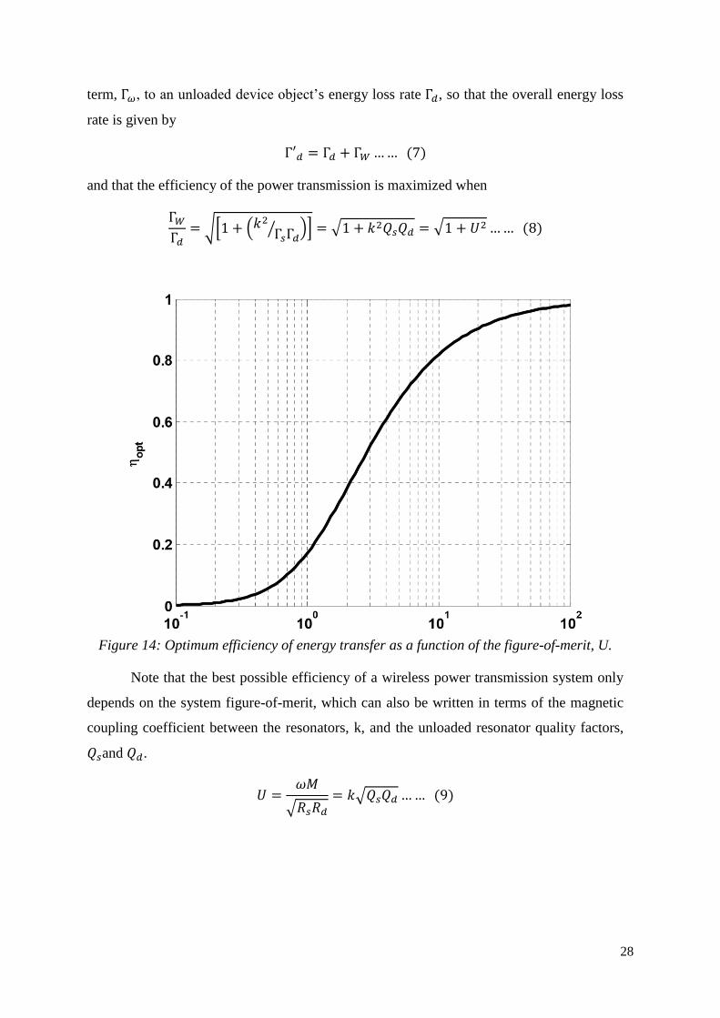
28
term, Γ𝜔, to an unloaded device object’s energy loss rate Γ𝑑, so that the overall energy loss
rate is given by
Γ′𝑑 = Γ𝑑 + Γ𝑊 … … (7)
and that the efficiency of the power transmission is maximized when
Γ𝑊
Γ𝑑= √[1 + (𝑘2
Γ𝑠Γ𝑑⁄ )] = √1 + 𝑘2𝑄𝑠𝑄𝑑 = √1 + 𝑈2 … … (8)
Figure 14: Optimum efficiency of energy transfer as a function of the figure-of-merit, U.
Note that the best possible efficiency of a wireless power transmission system only
depends on the system figure-of-merit, which can also be written in terms of the magnetic
coupling coefficient between the resonators, k, and the unloaded resonator quality factors,
𝑄𝑠and 𝑄𝑑.
𝑈 =𝜔𝑀
√𝑅𝑠𝑅𝑑
= 𝑘√𝑄𝑠𝑄𝑑 … … (9)

29
Knowing the resonator quality factors and the range of magnetic coupling between them for
a specific application, one can use Equations (6) and (9) to determine the best efficiency
possible for the system.
The wide range of applications capable of being supported by wireless power transfer
systems using HR-WiTricity can be estimated by examining Equations (6) and (9) that show
the importance of coupling factor and quality factor. The magnetic coupling coefficient is a
dimensionless parameter representing the fraction of magnetic flux that is coupled between
the source and device resonators, and has a magnitude between zero (no coupling) and 1 (all
flux is coupled). Wireless power transmission systems based on traditional induction (i.e.,
cordless toothbrush) typically are designed for larger values of coupling and as a result
require close spacing and precise alignment between source and device. Equations (6) and
(9) show that using high-quality resonators makes traditional induction systems even more
efficient, but perhaps more importantly, makes very efficient operation at lower coupling
values possible, eliminating the need for precise positioning between source and device and
providing for a greater freedom of movement.
3.4.3 Technology Benefits and Applications
The interest in highly resonant wireless power transfer comes from many markets and
application sectors. There are several motivations for using such technology, and these often
fall into one or more of the following categories:
1. Make devices more convenient and thus more desirable to purchasers, by eliminating
the need for a power cord or battery replacement.
2. Make devices more reliable by eliminating the most failure prone component in most
electronic systems—the cords and connectors.
3. Make devices more environmentally sound by eliminating the need for disposable
batteries. Using grid power is much less expensive and more environmentally sound
than manufacturing, transporting, and using batteries based on traditional
electrochemistries.
4. Make devices safer by eliminating the sparking hazard associated with conductive
interconnections, and by making them watertight and explosion proof by eliminating
connector headers and wires that run through roofs, walls or other barriers (even skin
tissue).

30
5. Reduce system cost by leveraging the ability to power multiple devices from a single
source resonator.
The high degree of scalability of power level and distance range in solutions based on
highly resonant wireless power transfer enables a very diverse array of configurations.
Applications range from very low power levels for wireless sensor and electronic devices
needing less than 1 watt, to very high power levels for industrial systems and electric vehicles
requiring in excess of 3 kilowatts. Furthermore, systems can be implemented for either or both
a) “Wireless Direct Powering” of a device, in which the captured energy is directly connected
to a load (e.g., LED lights) and any existing battery or energy storage component in the device
is not providing power or is providing back-up power; or b)”Wireless Charging”, in which a
battery or super capacitor is charged with the received energy. Examples of each are illustrated
in Figure 15.
Figure 15: Photographs of highly resonant wireless power transfer systems used to
wirelessly power and operate an LCD TV (~250 W supplied wirelessly) (left) and to
wirelessly charge a battery in a smart phone (~5 W supplied wirelessly) (right).
There are four (4) major functional benefits of using highly resonant wireless power
transfer systems as compared to systems based on traditional magnetic induction. The first is
the flexibility in the relative orientations of the source and device during operation. This
flexibility opens the application space as well as makes systems easier and more convenient to
use. Second, a single source can be used to transfer energy to more than one device, even when
the devices have different power requirements. For example, instead of having a separate
charger for each mobile phone in your family, you can have a charging surface that handles all
of them at once. Third, because of the ability to operate at lower magnetic coupling values, the
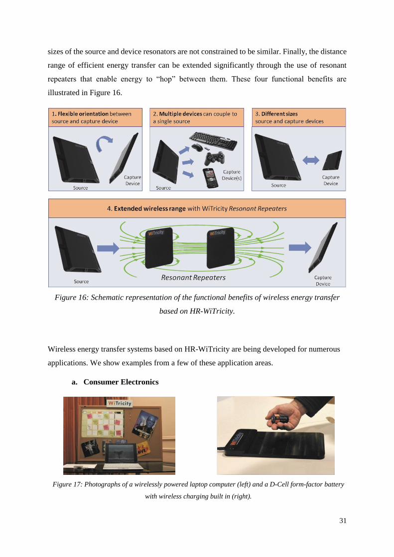
31
sizes of the source and device resonators are not constrained to be similar. Finally, the distance
range of efficient energy transfer can be extended significantly through the use of resonant
repeaters that enable energy to “hop” between them. These four functional benefits are
illustrated in Figure 16.
Figure 16: Schematic representation of the functional benefits of wireless energy transfer
based on HR-WiTricity.
Wireless energy transfer systems based on HR-WiTricity are being developed for numerous
applications. We show examples from a few of these application areas.
a. Consumer Electronics
Figure 17: Photographs of a wirelessly powered laptop computer (left) and a D-Cell form-factor battery
with wireless charging built in (right).

32
The laptop PC shown in the left photo in Figure 5 is being powered directly by a
wireless power source deployed behind the cork board, delivering over 20 watts of power
over a 40 cm distance. The source and device resonators are oriented perpendicular to each
other. In the photo on the right in Figure 17, the D cell form factor battery shown charging
is enabled for wireless energy capture, and can charge at a distance of over 10 cm from the
wireless charging source. Analysts expect that the benefits of charging over distance and
with spatial freedom will result in highly resonant wireless power transfer capturing over
80% market share of all wireless charging systems by 2020.
b. Medical Devices
Figure 18: Pictures showing two examples of HR-WiTricity charging applications in medical devices: Left
ventricular assist device (LVAD) (left) and pacemakers (right).
Wireless charging systems are being developed for implanted medical devices
including LVAD heart assist pumps, pacemakers, and infusion pumps. Using highly resonant
wireless power transfer, such devices can be efficiently powered through the skin and over
distances much greater than the thickness of the skin, so that power can be supplied to devices
deeply implanted within the human body. The HR-WiTricity technique eliminates the need
for drive lines that penetrate the human body, and for surgical replacement of primary
batteries.

33
c. Electric Vehicles
Figure 19: Photograph showing an application of HR-WiTricity for charging full electric
and hybrid vehicles.
Wireless charging systems are being developed for rechargeable hybrid and battery
electric vehicles. These systems already deliver 3.3 kW at high efficiency over a distance of
10 cm -20 cm (typical vehicle ground clearances). Figure 19 shows the Audi Urban Concept
Vehicle, demonstrated by Audi in April, 2012. It is expected that wireless charging will
vastly improve the charging experience for EV owners, making such vehicles even more
attractive to consumers.
d. LED Lighting
Figure 20: Photographs showing LED lights directly powered by highly resonant wireless
energy transfer systems.
LED (light emitting diode) lights can be directly powered with wireless electricity,
eliminating the need for batteries in under-cabinet task lighting, and enabling architectural
lighting designers to create products that seemingly float in mid-air, with no power cord. The
LED fixture shown in the left photo in Figure 20 is powered by a 10 W source mounted above

34
the ceiling, and using two resonant repeaters (the white disks) to improve the efficiency of
the energy transfer.
e. Defense Systems
Figure 21: Photographs showing several military applications for highly resonant wireless
charging systems: military robots (left) and soldier electronics (right).
Designers of defense systems are able to utilize wireless charging to improve the
reliability, ergonomics, and safety of electronic devices. The Talon tele-operated robot
shown in
Figure 21 is being equipped with wireless charging so that it can be recharged while it is
being transported by truck from site to site. Helmet mounted electronics, including night
vision and radio devices can be powered wirelessly from a battery pack carried in the soldier’s
vest, eliminating the need for disposable batteries or a power cord connecting the helmet to
the vest mounted battery pack.
Over the past few years a number of standards development organizations and industrial
consortia have initiated activities to develop specifications and standards relating to the
application and commercialization of wireless power. The Society of Automotive Engineers
(SAE) has a committee developing recommendations and ultimately a standard for wireless
charging of electric and hybrid electric vehicles (cars and buses). Outside of North America,
other international (International Electro technical Commission, or IEC) and national
organizations (e.g., DKE German Commission for Electrical, Electronic & Information
Technologies and the Japanese Automobile Research Institute, among others) are doing the
same. The Consumer Electronics Association (CEA) is active in developing a standard for the
deployment of wireless power technologies in consumer applications. Also, several industry
consortia have been established to develop specifications for components and systems (e.g.,

35
Wireless Power Consortium (WPC), Power Matters Alliance (PMA), and Alliance for Wireless
Power (A4WP)). These efforts should help speed the adoption of wireless power technology
across a varied application space.

36
Chapter 4 Practical application of WiTricity
4.1 Components:
Type Name Quantity Value
Transistor IRFZ44N 2 ______
Capacitor 1 WIMA FKP 1 6 6.8 nF (1000 V)
Capacitor 2 _____ 1 100 nF (63V)
Capacitor 3 PHILIPS metal 1 47 nF
Inductor _____ 2 100 µH (3A)
Diode 1N4148 2 ______
Heat Sink SK129 2 ______
Resistance 1 _____ 2 100 Ω (1W)
Resistance 2 _____ 2 10 kΩ (1/4 W)
Resistance 3 _____ 2 1kΩ (1/4 W)
LED _____ 2 _____
Copper Tube _____ 2 6.6 µH
Board
Table 1: Components required
4.2 Concept of working
We was working on a concept design which has a bunch of electronics in a board that
communicates together to create a high resonance circuit. First thing we needed to do was to
power the electronics so we looked for a wireless power transmitter design and we found one
which is simple, at least in terms of construction, and works really well.
This is a wireless transmitter and receiver project. The transmitter is based on the "Witricity"
series.

37
Figure 22: The schematic of the transmitter circuit
4.3 Steps:
1- Print and itch the board.
2- Gather the components on the board. (as it is shown in appendix B)
3- Test the board connectivity.
4- Test the board and see the frequency differences.
5- According to Step 4, build the receiver circuit.
6- Test the transmission between the transmitter and the receiver.
7- Get the results, efficiency and losses.
4.4 Building the receiver:
According to step 4, we got almost (57 KHz) of frequency from the receiver, so we
can easily calculate the resonance circuit of the receiver.
We have a copper tube with a diameter of 6mm, shaped as horseshoe, and has a reactance of
(0.208 µH).
By connecting the copper tube in parallel with an appropriate capacitor we can get a
resonance circuit that fits with the transmitter frequency.
𝑓 =1
2 ∙ 𝜋 ∙ √𝐿 ∙ 𝐶
38
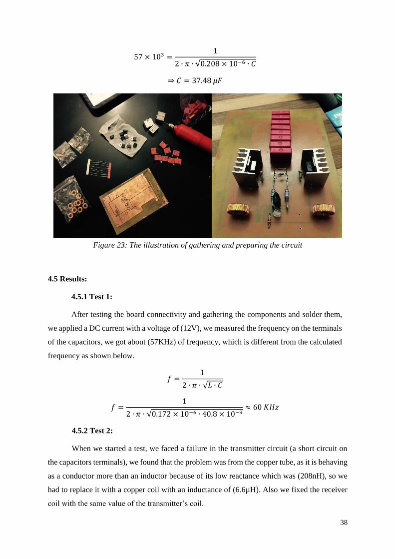
57 × 103 =1
2 ∙ 𝜋 ∙ √0.208 × 10⁻⁶ ∙ 𝐶
⇒ 𝐶 = 37.48 𝜇𝐹
Figure 23: The illustration of gathering and preparing the circuit
4.5 Results:
4.5.1 Test 1:
After testing the board connectivity and gathering the components and solder them,
we applied a DC current with a voltage of (12V), we measured the frequency on the terminals
of the capacitors, we got about (57KHz) of frequency, which is different from the calculated
frequency as shown below.
𝑓 =1
2 ∙ 𝜋 ∙ √𝐿 ∙ 𝐶
𝑓 =1
2 ∙ 𝜋 ∙ √0.172 × 10⁻⁶ ∙ 40.8 × 10⁻⁹≈ 60 𝐾𝐻𝑧
4.5.2 Test 2:
When we started a test, we faced a failure in the transmitter circuit (a short circuit on
the capacitors terminals), we found that the problem was from the copper tube, as it is behaving
as a conductor more than an inductor because of its low reactance which was (208nH), so we
had to replace it with a copper coil with an inductance of (6.6µH). Also we fixed the receiver
coil with the same value of the transmitter’s coil.

39
After changing all the parameters of the two circuits, we need to measure the frequency
and recalculate the capacitance needed for the receiver circuit.
We have a frequency of (285 KHz) and an inductance of (6.6µH) in the receiver circuit,
then we can easily calculate the capacitor needed as following:
𝑓 =1
2 ∙ 𝜋 ∙ √6.6 × 10⁻⁶ ∙ 𝐶≈ 285 𝐾𝐻𝑧
⇒ 𝐶 = 47.1 𝑛𝐹
After applying the previous results on the circuit, we tested it, and we got the results:
The output voltage of the transmitter was about (28V), with a current flow of (250mA), and
after measuring the input of the receiver we got about (18V) with a distance from the
transmitter of (5cm). And the current flow of (350mA).
𝜂 =𝑃𝑜𝑢𝑡
𝑃𝑖𝑛× 100% =
18 × 350 × 10−3
28 × 250 × 10−3× 100 = 90%
Figure 24: Range Distance of (5cm)

40
There was a lot of losses in a high distance according to our circuit. We could measure a
voltage of (6V) and a current about (100mA) in a distance range of (15cm).
𝜂 =𝑃𝑜𝑢𝑡
𝑃𝑖𝑛× 100% =
6 × 100 × 10−3
28 × 250 × 10−3× 100 = 8.57%
Figure 25: Range Distance of (15cm)

41
Chapter 5 Human Safety Considerations
A common question about wireless energy transfer systems using HR-WiTricity is: Are
they safe?
Perhaps because these systems can efficiently exchange energy over mid-range
distances, people may assume that they are being exposed to large and potentially dangerous
electromagnetic fields when using these systems. Early popular press descriptions of the
technology as “electricity-in-the-air” have done little to calm people’s potential fears.
Of course, WiTricity’s technology is NOT “electricity-in-the-air”, but rather a
technology that uses oscillating magnetic fields to mediate the wireless energy exchange. With
proper design the stray electric and magnetic fields can be kept below the well-established and
long-standing human safety limits that regulate all electro-magnetic consumer devices
including cell phones, wireless routers, Bluetooth headphones, radio transmitters, etc. The high
quality factor resonators used in WiTricity systems have very low loss rates, and so can
efficiently store energy and transfer power efficiently over distance, even when the magnitude
of the magnetic fields is very low.
In this section, we will discuss what the human safety limits are, where they come
from, and how it is established that wireless power systems conform to these safety limits.
The safety limits for human exposure to electromagnetic fields are determined by on-
going reviews of scientific evidence of the impact of electromagnetic fields on human health.
The World Health Organization (WHO) is expected to release a harmonized set of human
exposure guidelines in the near future. In the meantime, most national regulations reference,
and the WHO recommends, the human exposure guidelines determined by the Institute of
Electrical and Electronic Engineers (IEEE) and by the International Commission on Non-
Ionizing Radiation Protection (ICNIRP).
The purposes of the IEEE and ICNIRP guidelines are similar:
“The main objective of this publication is to establish guidelines for limiting EMF
(electromagnetic field) exposure that will provide protection against known adverse
health effects. An adverse health effect causes a detectable impairment of the health of
the exposed individual or of his or her offspring; a biological effect on the other hand,
may or may not result in an adverse health effect”. [ICNIRP]
42
“The purpose of this standard is to provide exposure limits to protect against
established adverse health effects to human health induced by exposure to RF (radio
frequency) electric, magnetic, and electromagnetic fields over the frequency range of 3
kHz to 300 GHz.”[IEEE]
In their most recent reviews of the accumulated scientific literature, both the IEEE and
ICNIRP groups have concluded that there is no established evidence showing that human
exposure to radio frequency (RF) electromagnetic fields causes cancer, but that there is
established evidence showing that RF electromagnetic fields may increase a person’s body
temperature or may heat body tissues and may stimulate nerve and muscle tissues. The ICNIRP
group also concludes that the induction of retinal phosphenes may be considered in determining
human exposure limits. Both groups recommend limiting human exposure to electromagnetic
field strengths that are well below those that cause the adverse effects described above. In the
case of tissue heating, the IEEE and ICNIRP recommend limiting the specific absorption rate
or SAR, a measure of the amount of electromagnetic energy absorbed by the human body and
turned into heat. In the case of electro-stimulation of nerve and muscle tissues and the induction
of retinal phosphenes, the groups recommend limiting the internal electric field.
The SAR and internal E-field limits are referred to as basic restrictions (BRs) because they are
“based on the physical quantity or quantities directly related to the established health
effects.”[ICNIRP]
5.1 Tissue Heating
For the case of tissue heating and/or body temperature increases, both the IEEE and
ICNIRP have determined that even the most sensitive human tissues are not adversely affected
when the whole-body averaged (WBA) SAR levels are less than 4 W/kg, corresponding to a
maximum body temperature rise of 1 °C, under normal environmental conditions. However,
neither group recommends setting the WBA SAR at 4 W/kg. Rather, both groups recommend
including a so-called “safety factor” or “reduction factor” meant as a cautionary step to
compensate for incomplete scientific data and also public perception. The IEEE and ICNIRP
recommend a whole body average SAR limit of 0.4 W/kg, for workers in controlled
environments (also called occupational exposure), and a SAR limit of 0.08 W/kg for the general
public.

43
Note that the 0.08 W/kg limit is the whole body average or WBA SAR, and
corresponds to effects when a person’s whole body is exposed to an electromagnetic field.
However, under conditions of non-uniform or localized exposure, it is possible that the
temperature of certain areas of the body may be raised by more than 1 °C, even though the
average field does not exceed the whole body SAR limit. To accommodate these
circumstances, recommendations are also made for limiting the localized field exposure.
In general, these limits are larger because temperature rises induced by localized
electromagnetic fields may be dissipated by conduction to cooler surrounding regions of the
body and by cooling mechanisms associated with blood flow. Therefore, the localized SAR
values are volume-averaged and are chosen to be small enough to avoid excessive temperature
gradients over the extent of the volume but large enough to obtain an average SAR that
corresponds well to the actual temperature increase throughout the volume. The IEEE and
ICNIRP recommend a localized general public SAR limit of 4 W/kg for limbs and 2 W/kg for
the head and trunk in 10 g of tissue. We note that for the United States, the Federal
Communications Commission (FCC) has adopted a more stringent SAR limit of 1.6 W/kg
averaged over 1 g of tissue.
SAR [W/kg]
(Whole Body
Average)
SAR [W/kg]
(Head/Trunk)
SAR [W/kg]
(Limbs)
Induced E
[V/m]
(All Tissue)
Induced J
[mA/m2]
(Central
Nervous
System)
FCC 0.08 1.6 (1 g) 4 (10 g) -- --
ICNIRP
2010 0.08 2.0 (10 g) 4 (10 g)
1.35 x 10⁻⁴ f
(f in Hz) --
ICNIRP
1998 0.08 2.0 (10 g) 4 (10 g) --
f/500
(f in Hz)
Table 2. Recommended SAR, induced electric field, and induced current (in the central
nervous system) levels by ICNIRP, and the FCC regulations for those same quantities.
44
5.2 Nerve and Muscle Stimulation
For the case of muscle and nerve stimulation, both the IEEE and ICNIRP have
identified field levels that stimulate very minor and short-lived effects on the central nervous
system, such as the production of visual phosphenes in the eyes, which may cause a faint
flickering visual sensation, as the effect to be avoided. While both groups acknowledge that
these minor effects are not associated with any adverse health effects, they have at least
temporarily decided to set recommended field limits at very conservative values, with the
intention of refining the recommended limits as data continues to emerge.
The general population internal electric field limits recommended by ICNIRP are
similar but slightly lower than IEEE. ICNIRP recommends an internal E-field limit of 1.35 x
10-4 *f V/m, where f is the frequency of the electromagnetic field in Hertz. The IEEE
recommends internal E-field limits that range from 2.1 × 10⁻⁴ × 𝑓(𝑣𝑚⁄ ) to 6.3 × 10⁻⁴ ×
𝑓(𝑣𝑚⁄ ) depending on which part of the body is exposed.
Note that both the IEEE and ICNIRP acknowledge that it may be difficult to determine
the basic restrictions because they require either sophisticated measurement techniques and/or
computational capabilities, so more conservative but easier to determine reference levels
(ICNIRP) or maximum permissible exposures (IEEE) are also provided to help determine
compliance with the limits:
“Because of the difficulty in determining whether an exposure complies with the basic
restrictions (BRs), derived limits (MPEs) to protect against adverse health effects
associated with heating are provided below for convenience in exposure assessment.”
[IEEE]
“The internal electric field is difficult to assess. Therefore, of practical exposure
assessment purposes, reference levels of exposure are provided.” [ICNIRP]
Oddly enough, despite the agreement between the IEEE and ICNIRP groups on what
the basic restrictions should be, the two groups used very different estimation and scaling
techniques to develop the MPE’s/Reference Levels.
The MPE’s and Reference Levels are often referred to in the literature as the limits
recommended by the IEEE and ICNIRP, but they are not. They are simply easily measureable
electric and magnetic field levels in free space, that guarantee the BRs are met if measured
field levels are below these levels. Both the IEEE and ICNIRP guidelines are quite clear that

45
the MPEs/Reference Levels are for convenience, and that it is quite possible that systems whose
field levels exceed these MPE’s/Reference Levels may still comply with the ultimate limits,
the basic restrictions.
5.3 Electromagnetic simulations
At WiTricity, we have developed the sophisticated modeling tools necessary to assess
compliance with the basic restrictions recommended by the IEEE and ICNIRP. Our
electromagnetic simulations are performed using the finite-element method (FEM) in the
frequency domain. Although it is common to utilize finite-difference time-domain (FDTD)
methods for these types of studies, FEM holds several advantages and is also being used. First,
in an FDTD simulation the maximum time step must be chosen to meet the Courant-Friedrichs-
Levy stability condition, which means the number of time steps required for an FDTD
simulation scales as the free space wavelength of light (1,200 m for a 250 kHz operating
frequency) over the size of the computational cell (~1 cm in the present case). The low
frequencies used for wireless power transfer would translate to very long simulation times. As
our FEM simulations are performed directly in the frequency domain rather than propagated in
the time domain, they do not suffer from this poor low-frequency scaling. Second, in a FDTD
simulation, voxel-based models of the human body must be used. In this case, the rectangular
voxel grids may not line up with the curved boundaries between different body tissues. The
actual simulations will therefore use stair-cased representations of the tissue boundaries, which
can have the effect of introducing large inaccuracies in the electromagnetic fields at these
boundaries. One approach to circumvent these problems is to simply discard the upper 1% of
field values before performing the various field averages, but this procedure is entirely
uncontrolled and can result in significant inaccuracies. For FEM simulations, the mesh can be
forced to conform to the boundaries between different tissues, removing these stair-casing
effects.

46
5.4 Human body models
In order to create anatomically accurate finite-element mesh models of the human body,
we started with the Virtual Family dataset, which consists of high-resolution CAD models
obtained from MRI scan data. We then created a voxel grid from this dataset, and generated
the FEM mesh from the voxel grid. Electromagnetic properties of the various tissues involved
(muscle, bone, skin, etc.) are frequency dependent; we use values taken from studies in the
literature.
As one example of the simulation process using the human body models, consider the
case of a person standing next to a vehicle being wirelessly charged. Figure 19 shows a
WiTricity wireless vehicle charging system similar to that used in this simulation. The
simulation was performed with the system operating at 145 kHz and transferring 3.3 kW to the
load. For this case the leg closest to the vehicle (at approximately 65 cm from the wireless
charging system) will experience the highest fields and is the relevant portion of the human
body to include in the simulation. The car is modeled as a block of aluminum. The calculated
electric field in the leg is shown on the left side of the figure while the calculated peak SAR is
shown on the right. In both cases, the values are displayed relative to the most stringent basic
restriction levels (ICNIRP for electric field and FCC for SAR). Both measures are well below
the guidelines; the largest electric field is -19 dB and the peak SAR value is -36 dB relative to
the guidelines. Thus, the highly resonant vehicle charging system shown in Figure 19 is
completely safe, as the SAR and internal E-field levels for people standing directly against a
vehicle are well below the established guideline limits. Note that Figure 26 (right) shows the
peak SAR values in the FEM simulation grid which are larger than what would be obtained by
averaging over the 1 gram volume of tissue as the FCC regulations state. However, even these
over-estimated SAR values are significantly below the limits set by the FCC.

47
Figure 26: Calculated electric field (left) and specific absorption rate (right) for a leg next to
a vehicle being wirelessly charged at 3.3 kW. The values are normalized to the most stringent
basic restriction levels (ICNIRP electric field and FCC SAR).
A second example is a cell phone being wirelessly charged on a pad, similar to the
photo in Figure 15. In this use case, the system is operating at 6.78 MHz and the phone is
receiving 5 W from the wireless system. The geometry is a phone located on a source pad, with
a hand placed on top of the phone while charging is taking place. The fields are largest on the
palm of the hand, and the top plots in Figure 26 show the computed electric field and peak SAR
values for this portion of the hand. The bottom plots show the computed electric field and peak
SAR values for the top portion (back) of the hand. In general, as the frequency of operation is
increased, the SAR values become larger and the electric field smaller relative to the guidelines.
This is evident in Figure 26 where the largest electric field value is -20 dB relative to the
guideline, while the SAR value is closer to the guideline limit. The same use case was simulated
with a system operating at 250 kHz and the results (not shown here) are basically reversed from
those in Figure 26, i.e., the electric field is closer to the guidelines while the SAR results are
far below. Note that these results show that a highly resonant cell phone charging system, is
completely safe, as the SAR and internal E-field levels for people holding phones while they

48
are charging are well below the established guideline limits. As in Figure 26, Figure 27 (right)
shows the peak SAR values in the FEM simulation grid which are larger than what would be
obtained by averaging over the 1 gram volume of tissue as the FCC regulations state. However,
even these over-estimated SAR values are significantly below the limits set by the FCC.
Figure 27: Calculated electric field (left) and specific absorption rate (right) in a hand
resting on a phone being wirelessly charged at 5 W. The values are normalized to the most
stringent basic restriction levels ((ICNIRP electric field and FCC SAR).

49
Appendix A
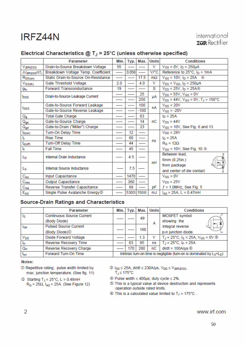
50
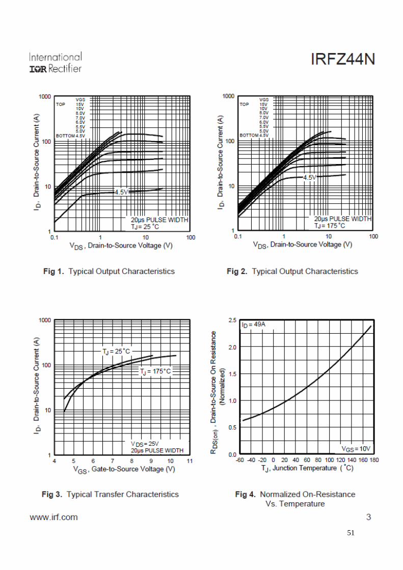
51

52
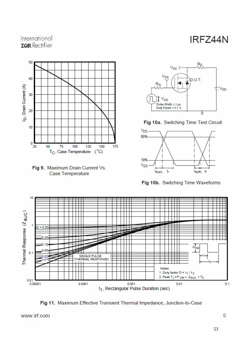
53
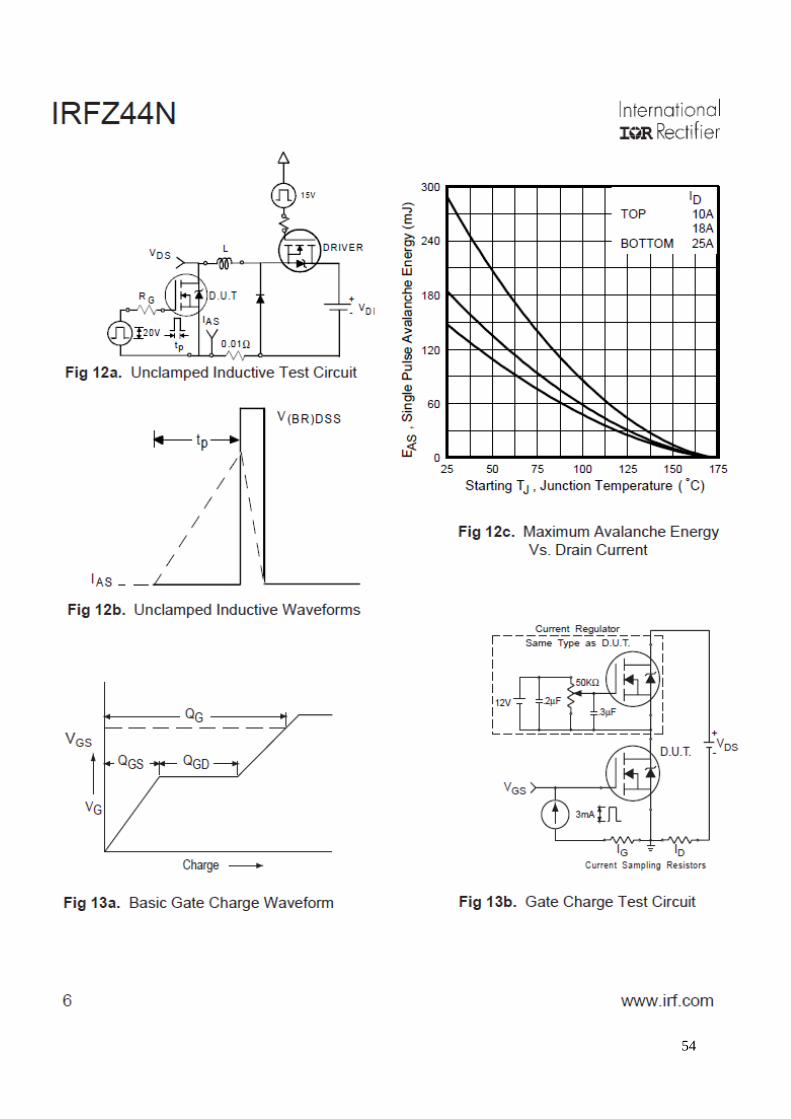
54

55

56

57
Appendix B
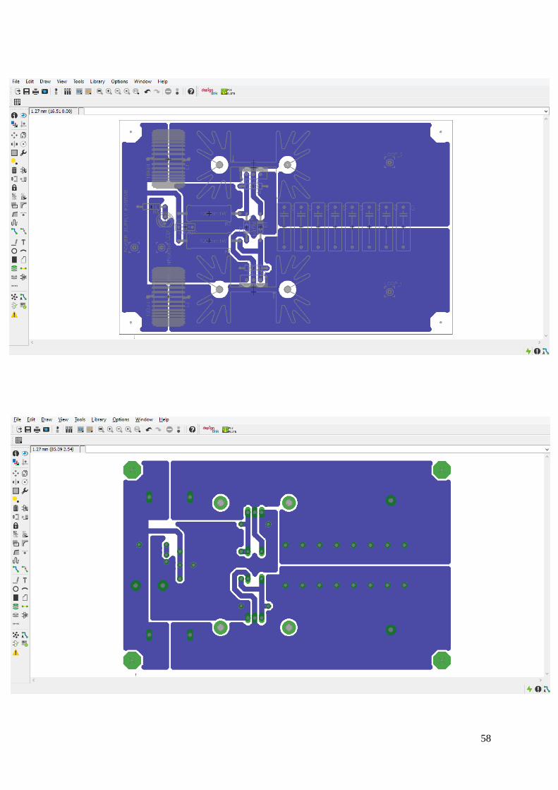
58

59
References
1- Abel, E. and S. Third, “Contactless power transfer, an exercise in topology,” IEEE
Trans. on Magnetics, Vol. 20, No. 5, 1813–1815, 1984
2- http://www.esa.int/gsp/ACT/doc/POW/ACT-RPR-NRG-2009-SPS-ICSOS-concepts-
for-laser-WPT.pdf
3- http://www.itis.ethz.ch/services/anatomical-models/static-models/
4- http:// www.comsol.com.
5- http://en.wikipedia.org/wiki/Nikola_Tesla
6- IFAC website “An Internet Resource for the Calculation of the Dielectric Properties
of Body Tissues”, http://niremf.ifac.cnr.it/tissprop/
7- “IEEE Standard for Safety Levels with Respect to Human Exposure to Radio
Frequency Electromagnetic Fields, 3 kHz to 300 GHz”, IEEE Std. C95.1-2005.
8- Kaur S. Pushing frontiers with the first lady of emerging technologies - How is
wireless power transmission going to affect our lives?. IETE Tech Rev 2012;29:259-
64
9- Wireless Power Consortium, Qi Specification Version 1.1,
http://www.wirelesspowerconsortium.com/developers/specification.html
10- American society of electrical engineers.

VIII
Table of Figures
Figure 1: A schematic View of the gapped coaxial WPT system ...............................................3
Figure 2: Cross section of the gapped coaxial WPT system.......................................................3
Figure 3: Transmission and absorption in Earth atmosphere ................................................10
Figure 4: Classification of satellite communication systems by beam divergence and data
rate ................................................................................................................................................10
Figure 5: EADS developed, fully laser powered autonomous rover .......................................13
Figure 6: Spectral output of several types of lasers ..................................................................15
Figure 7: JAXA L-SPS 100x200 m reference unit delivering 10 MW via direct solar
pumped lasers ...............................................................................................................................19
Figure 8: JAXA L-SPS fully deployed reference system delivering 1 GW via direct solar
pumped lasers ...............................................................................................................................19
Figure 9: JAXA L-SPS system diagram ....................................................................................19
Figure 10: Block diagram of a wireless energy transfer system ..............................................22
Figure 11: Schematic representation of inductively coupling into and out of the resonators
........................................................................................................................................................24
Figure 12: Example of a resonator .............................................................................................25
Figure 13: Equivalent circuit for the coupled resonator system .............................................26
Figure 14: Optimum efficiency of energy transfer as a function of the figure-of-merit, U ..28
Figure 15: Photographs of highly resonant WPT systems used to wirelessly power and
operate an LCD TV and to wirelessly charge a battery in a smart phone .............................30
Figure 16: The functional benefits of wireless energy transfer based on HR-WiTricity ......31
Figure 17: Photographs of a wirelessly powered laptop computer (left) and a D-Cell form-
factor battery with wireless charging built in (right) ...............................................................31

IX
Figure 18: Pictures showing two examples of HR-WiTricity charging applications in
medical devices: Left ventricular assist device (LVAD) (left) and pacemakers (right) ........32
Figure 19: Photograph showing an application of HR-WiTricity for charging full electric
and hybrid vehicles ......................................................................................................................33
Figure 20: Photographs showing LED lights directly powered by highly resonant wireless
energy transfer systems ...............................................................................................................33
Figure 21: Photographs showing several military applications for highly resonant wireless
charging systems: military robots (left) and soldier electronics (right) ..................................34
Figure 22: The schematic of the transmitter circuit .................................................................37
Figure 23: The illustration of gathering and preparing the circuit.........................................38
Figure 24: Range Distance of (5cm) ...........................................................................................39
Figure 25: Range Distance of (15cm) .........................................................................................40
Figure 26: Calculated electric field (left) and specific absorption rate (right) for a leg next
to a vehicle being wirelessly charged at 3.3 kW. The values are normalized to the most
stringent basic restriction levels (ICNIRP electric field and FCC SAR) ................................47
Figure 27: Calculated electric field (left) and specific absorption rate (right) in a hand
resting on a phone being wirelessly charged at 5 W. The values are normalized to the most
stringent basic restriction levels ((ICNIRP electric field and FCC SAR)...............................48

X
Table of Tables
Table 1: Components required ..................................................................................................36
Table 2. Recommended SAR, induced electric field, and induced current (in the central
nervous system) levels by ICNIRP, and the FCC regulations for those same quantities ......43