Embed Size (px)
Citation preview

NCR Planning Board Asian Development Bank
Capacity Development of the National Capital Region Planning Board (NCRPB) – Component B (TA No. 7055-IND)
FINAL REPORT Volume I-C: Detailed Project Report for Panipat Water Supply
Detailed Specifications
July 2010
i
Contents 1. GENERAL SPECIFICATIONS ................................................................................................................. 1
A. EQUIVALENCY OF STANDARDS AND CODES ............................................................................................... 1 B. SIGN DEPARTMENT .................................................................................................................................... 1 C. SAMPLES AND TESTS .................................................................................................................................. 1 D. PROTECTION OF UTILITIES ......................................................................................................................... 2
2. EARTHWORK ............................................................................................................................................ 2 A. EARTH WORK ............................................................................................................................................. 2 B. DISPOSAL OF SURPLUS EXCAVATED MATERIAL......................................................................................... 3 C. SECTIONS FOR EXCAVATION FOR ALL UNDERGROUND STRUCTURES AND PIPE LINES .................................. 5 D. FOUNDATION FOR PUMPS, MOTORS AND TRANSFORMERS ......................................................................... 5 E. CLASSIFICATION OF EXCAVATION .............................................................................................................. 5 F. LIMITS OF EXCAVATION ............................................................................................................................. 6 G. TRIAL PITS .................................................................................................................................................. 6 H. SLIPS AND SLIDES ....................................................................................................................................... 6 I. STACKING OF EXCAVATED MATERIAL ........................................................................................................ 6 J. SAFETY MEASURES ..................................................................................................................................... 6 K. PROGRESS OF EXCAVATION OF PIPE TRENCHES .......................................................................................... 7 L. SHORING AND BRACING ............................................................................................................................. 7 M. EXCAVATION IN ROCK ........................................................................................................................... 7 N. BLASTING OF ROCK .................................................................................................................................... 7 O. EXCAVATION FOR INLETS, JUNCTION CHAMBERS AND OTHER APPURTENANT STRUCTURES ..................... 8 P. CONTRACTOR'S RESPONSIBILITY ................................................................................................................ 8 Q. WORKS INCLUDED IN EXCAVATION ........................................................................................................... 9 R. BEDDING FOR THE PIPE ............................................................................................................................... 9 S. BACKFILLING OF TRENCHES AND AROUND FOUNDATIONS OF STRUCTURES ............................................. 10 T. REFILLING OF TRENCHES OF PIPE LINE:- .................................................................................................. 12 U. FILLING TRENCHES WITH STONE DUST:- .................................................................................................. 12 V. RESTORING ROAD TO THEIR ORIGINAL LEVEL:- ....................................................................................... 13 W. DISPOSAL OF SURPLUS EXCAVATED MATERIAL .................................................................................. 13
3. DETAILED SPECIFICATIONS FOR PIPE LINE WORKS ............................................................... 14 A. DUCTILE IRON PIPES .......................................................................................................................... 14 B. M.S. PIPES .............................................................................................................................................. 16 C. HDPE PIPES ........................................................................................................................................... 18 D. GLASS FIBER REINFORCED PLASTIC (GRP) PIPES, FITTINGS AND SPECIALS ........................................... 24
4. VALVES ..................................................................................................................................................... 30 A. GENERAL ................................................................................................................................................. 30 B. SLUICE VALVES. ...................................................................................................................................... 31 C. AIR VALVES (TAMPER PROOF) ................................................................................................................. 33 D. DOUBLE FLANGED BUTTERFLY VALVES CONFORMING TO IS 13095 WITH ISI MARK ............................. 34 E. DUAL PLATE NON RETURN VALVES ........................................................................................................ 35
5. PIPE JOINTING ........................................................................................................................................ 36 A. BETWEEN STEEL PIPES OR STEEL PIPES AND SPECIALS ............................................................................ 36 B. JOINTING OF VALVES AND SPECIALS ........................................................................................................ 36
6. PROCESS VALIDATION ........................................................................................................................ 37 7. PROTECTION AGAINST FLOATATION DUE TO UPLIFT PRESSURE. ..................................... 37 8. CIVIL SPECIFICATIONS ....................................................................................................................... 37
A. SITE CLEARANCE ..................................................................................................................................... 37 B. DESIGN OF STRUCTURES ........................................................................................................................... 37 C. WATER FOR HYDRAULIC TESTING ............................................................................................................ 39 D. WATER FOR DRINKING AND CONSTRUCTION WORK ................................................................................. 39
ii
E. POWER FOR CONSTRUCTION WORK AND STAND BY DIESEL GENERATOR SET.......................................... 39 F. SURVEYING INSTRUMENTS ....................................................................................................................... 39
9. STRUCTURAL CONCRETE AND MORTAR ...................................................................................... 40 A. GRADE OF CONCRETE .............................................................................................................................. 40 B. STRENGTH REQUIREMENT OF CONCRETE ................................................................................................. 41 C. USE OF PLUMS IN ORDINARY CONCRETE ................................................................................................. 41
10. ANCILLARY STRUCTURES ............................................................................................................. 42 A. VALVE CHAMBERS, THRUST BLOCKS/ANCHOR BLOCKS .......................................................................... 42
11. PIPE LINE CONNECTIONS ............................................................................................................... 43 A. CROSSINGS OF ROADS AND CULVERTS..................................................................................................... 44
12. PROVIDING & INSTALLING BULK & DOMESTIC WATER METERS WITH STRAINERS 44
A. TECHNICAL SPECIFICATIONS FOR 15/20/25/32MM DOMESTIC WATER METERS ....................................... 44 B. APPLICABLE STANDARDS ......................................................................................................................... 44 C. NOMINAL CAPACITY ................................................................................................................................ 45 D. ACCURACY CLASS ................................................................................................................................... 45 E. ACCURACY AT 0,5 QMIN .......................................................................................................................... 45 F. PRESSURE AND TEMPERATURE ................................................................................................................. 45 G. PRESSURE LOSS ........................................................................................................................................ 45 H. METER MARKINGS ................................................................................................................................... 46 I. ACCESSORIES ........................................................................................................................................... 46 J. CONFORMANCE TO METER TESTING ........................................................................................................ 46 K. METER SIZE AND OVERALL DIMENSIONS .................................................................................................. 47 L. SEAL ........................................................................................................................................................ 47 M. SPECIFICATIONS FOR INSTALLATION OF METERS ................................................................................. 47
13. SPECIFICATION FOR WOLTMANN TYPE BULK METERS CLASS B ................................... 47 A. SCOPE ....................................................................................................................................................... 47 B. MATERIALS .............................................................................................................................................. 47 C. GENERAL ................................................................................................................................................. 48 D. MARKINGS ............................................................................................................................................... 49 E. STRAINER ................................................................................................................................................. 49
14. TECHNICAL SPECIFICATION FOR BULK POTABLE WATER METERS (FULL BORE ELECTROMAGNETIC FLOWMETERS) ..................................................................................................... 50 15. SERVICE CONNECTIONS ................................................................................................................. 52
A. OPTION 1 .................................................................................................................................................. 52 B. OPTION 2 .................................................................................................................................................. 53 C. ITEMS COMMON FOR BOTH OPTIONS: ........................................................................................................ 53
16. TECHNICAL SPECIFICATIONS FOR ELECTRO FUSION TAPPING ..................................... 53 17. INSTALLATION AND FUSION JOINTING .................................................................................... 56 18. ELECTRO FUSION WELDING MACHINE .................................................................................... 56 19. COMPRESSION FITTINGS ............................................................................................................... 57
A. MATERIAL OF CONSTRUCTION ................................................................................................................. 57 B. PRESSURE TESTING ................................................................................................................................... 58 C. DIMENSIONS ............................................................................................................................................. 58 D. PERFORMANCE REQUIREMENTS ................................................................................................................ 58 E. EFFECTS ON QUALITY OF WATER ............................................................................................................. 58
20. U PVC BALL VALVES (STOP COCKS) ........................................................................................... 59 A. GENERAL ................................................................................................................................................. 59 B. PRESSURE RATING ................................................................................................................................... 59 C. DIMENSIONS ............................................................................................................................................. 59
iii
D. PERFORMANCE REQUIREMENTS: .............................................................................................................. 59 21. MDPE PIPES ......................................................................................................................................... 60
A. RAW MATERIAL ....................................................................................................................................... 60 B. EFFECTS ON WATER QUALITY ................................................................................................................. 60 C. PRESSURE RATING ................................................................................................................................... 60 D. COLOUR OF PIPES ..................................................................................................................................... 60 E. DIMENSIONS ............................................................................................................................................. 61 F. PERFORMANCE REQUIREMENTS ................................................................................................................ 61
22. SPECIFICATION FOR TUBSETTLER MEDIA .............................................................................. 61
1
1. GENERAL SPECIFICATIONS
A. Equivalency of Standards and Codes Wherever reference is made in the Contract to specific standards and codes to be met by
the goods and materials to be furnished, and work performed or tested, the provisions of the latest current edition or revision of the relevant standards and codes in effect shall apply, unless otherwise stated in the Contract. Where such standards and codes are national, or relate to a particular country or region, other authoritative standards that ensure an equal or higher quality than the standards and codes specified will be acceptable subject to the Engineer's prior review and written approval. Differences between the standards specified and the proposed alternative standards must be fully described in writing by the Contractor and submitted to the Engineer at least 28 days prior to the date when the Contractor desires the Engineer's approval. In the event the Engineer determines that such proposed deviations do not ensure equal or higher quality, the Contractor shall comply with the standards specified in the documents.
B. Sign Department The Contractor shall provide a sign Department at the site of the Works of approved size
and design which provides (i) the name of the Project (ii) the names and addresses of the Employer, the Contractor and the Consultant; (iii) the name and short description of the Project, (iv) the amount of the Contract Price; and (v) the starting and completion dates.
C. Samples and Tests Pursuant to other clauses in this contractor, the Contractor shall be responsible to develop
a quality control program and to provide all necessary materials, apparatus, instruments, equipment, facilities and qualified staff for sampling, testing and quality control of the materials and the works under the Contractor. Without limiting the generality of the foregoing, the Contractor shall either (i) establish a testing laboratory at the site of Works which is adequately equipped and staffed to carry out all sampling and testing in accordance with the requirement set out in the General Specifications and/or these Special Specifications and provide all field equipment and apparatus as necessary to conduct all specified in-situ tests and/or any Tests on Completion, or (ii) arrange for routine sampling, testing and reporting, as required, through a certified independent testing laboratory acceptable to the Engineer. All costs of such sampling, testing and reporting of test results will be borne by the Contractor, and the Contractor shall include sufficient provisions in his tendered rates to allow for independent sampling and laboratory testing under the direction of the Engineer upto 5% of the required tests at no additional cost. The Contractor shall furnish certified copies of all test reports to the Engineer within 3 days of completion of the specified tests.

2
The Contractor shall, within 14 days after the date of the Letter of Acceptance, submit to the Engineer for his consent a detailed description of the arrangements for conducting the quality control program during execution of the Works, including details of his testing laboratory, equipment, staff and general procedures. If following submission, or at any time during the progress of Works, it appears to the Engineer that the Contractor's quality control program is not adequate to ensure the quality of the Works, the Contractor shall produce a revised program which will be adequate to ensure satisfactory quality control.
D. Protection of Utilities The Contractor is required to carefully examine the location of the Works and their
alignments and to make special enquiry's with all authorities concerning all utility lines such as water, sewers, gas pipe, telephone (underground and/or overhead) lines, electric cable (underground and/or overhead) lines, etc.; and to determine and verify to his own satisfaction the character, sizes, position and lengths of such utilities from authentic records. The Contractor shall be wholly responsible for the protection and/or facilitating relocation of such utilities as may be required, and shall not make any claim for extra work or extra time that may be required to protect or facilitate relocating such utilities. If any major shifting or realignment of water, sewers, gas pipes, electric and telephone lines is necessary due to their interference with the proposed Works, the same may be done by the Employer. The cost of such relocation will be borne by the Employer.
2. EARTHWORK
A. Earth Work The earth work excavation for laying of pipe shall be carried out, in general, as per
Chapter 10, Standard Specifications for Procurement of Project Works, as specified in Sub-Clause 15.7.5.1 for rising main and Clause 5 for the reservoir. Any additions or modifications specified in this Chapter shall be followed. The Contractor shall make all excavations required for laying and jointing of the pipeline and construction of pertinent structures as required by the project. Except where otherwise required by the project or instructed by the Engineer, all excavation shall be in open cut to the specified widths and depths. The Contractor is advised to satisfy himself with regard to the likely conditions that may be met with during the execution of the Works, with regard to the underground obstructions or conditions, necessary dewatering requirements etc., before quoting the rates.
While carrying out earthwork in excavation in foundation and trenches in all kinds of soil,
including boulders, soft and hard rock etc., the work shall be carried out as per Chapter 10: Standard Specifications. Wherever necessary, shoring and strutting as specified in the above mentioned specifications shall be provided.
Wherever allowed with prior written permission, blasting of hard rock may be done after
taking all the necessary precautions as provided in the local Laws and By-laws.
3
Excavated earth in trenches shall not be dumped within 1.5 m distance from both sides of the trench from the top. Barricading on the sides of the trenches shall be provided with caution sign Departments and sufficient red light arrangement during night.
Earthwork in backfilling the trenches with selected earth and with the earth taken from
borrow pits shall be done in layers of 150 mm, watered and well consolidated. The Contractor would be responsible for making foolproof dewatering arrangement. The
arrangement for the disposal of the water pumped out from the trenches up to the nearby drain shall be the responsibility of the Contractor.
B. Disposal of Surplus Excavated Material The Contractor shall have to cart the surplus excavated material from the site and dispose
off to the place decided by the Engineer.
4
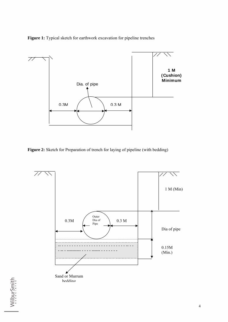
Figure 1: Typical sketch for earthwork excavation for pipeline trenches
Figure 2: Sketch for Preparation of trench for laying of pipeline (with bedding)
0.3M 0.3 M
1 M (Cushion) Minimum
Dia. of pipe
0.3M 0.3 M
1 M (Min)
Dia of pipe 0.15M (Min.)
Outer Dia of Pipe
-- - - - - - - - - - - - - - - - - - - - - - - - - - - -- - - - -- - ---------- - - - - ------ - - - - - - -
Sand or Murrum bedding
5
C. Sections for excavation for all underground structures and pipe lines Contractor shall prepare sectional drawings showing the details of excavation for all
underground structures and pipe lines, in all kinds of soils, boulders, soft and hard rock etc., based on test results of soil testing and investigation reports and shall submit to the Engineer for review and approval, prior to starting of the work. If during excavation any change in section is considered necessary for reasons of safety of workers, the Engineer will issue directions for compliance by the Contractor. The Contractor shall comply with the Engineer’s directions without any extra charge or payment.
D. Foundation for Pumps, Motors and Transformers The foundations for pumps and motors shall be designed based on sound engineering
practices, taking into consideration all vibration and other forces acting upon them. Foundations for transformers shall conform to IS: 10028 (Part-II).
E. Classification of Excavation All strata involved in excavation shall be classified as follows:
1. Ordinary soil This includes excavation in all types of soil including soil containing gravels, murums,
loose boulders, viz., ordinary gravelly soil, hard gravelly soil, wet soil, stiff slushy soil, chettu soil and cal carious strata, but exclusive of disintegrated rock, soft rock/shale.
2. Soil Containing Disintegrated Rock, Soft Rock and Soft Shale
This category includes excavation in soil containing disintegrated rock, soft rock or soft
shale which can be cut by shovel and no hand or mechanical chistelling is required.
3. Medium Hard rock This category includes excavation in lime stone, sand stone, hard shale and schist fissured
rock, without resorting to blasting.
4. Hard Rock This category includes excavation in hard rock requiring hand or mechanical chiselling or
blasting. In case of difference in opinion between the classification of rock requiring blasting and that requiring chiseling, wedging, the decision of the Engineer shall be final and binding on the Contractor.
6
F. Limits of excavation The Contractor shall be responsible to ensure that the widths and depths of the trenches do
not exceed the limits shown in the construction drawings. Should the excavation occur beyond the dimensions specified therein, because of the negligence of the Contractor, the Contractor shall fill the excess space with granular material or concrete as directed by the Engineer. Nothing extra shall be paid to the Contractor on account of this.
G. Trial pits The details of trial pits as shown on the alignment plans are only for general information.
There is no expressed or implied agreement or guarantee that depths or character of materials are correctly shown or the conditions affecting the work will not differ from those shown on the plans.
Trial pits may be dug by the Contractor, without being directed to do so, along the lines of
the trenches as shown on the drawings in advance of the excavations for the purpose of satisfying himself as to the location of under ground obstructions or soil conditions.
H. Slips and slides Pursuant to Clause 5.8 of Chapter 10, Standard Specifications for Procurement of Project
Works, the Contractor is responsible for proper protection of excavations made by him from any slips and slides. All slides and caving shall be handled, removed or corrected by the Contractor without any extra compensation at whatever time and under whatever circumstances they may occur. The excavations shall be made good and brought to necessary depth, width and levels without any extra cost.
I. Stacking of excavated material Pursuant to Clause 15.7.5.1, item 7 of Chapter 10, Standard Specifications for
Procurement of Project Works, the excavated material shall be stacked at least 600 mm away from the sides of the trench.
J. Safety measures The Contractor shall provide adequate safety measures during excavation. They shall
include: (i) Barricading all sides of the open trenches. (ii) Red danger lights as can be easily visible from dusk to dawn at an interval of 20 m
and at all the road crossings. (iii). Traffic signals and display Departments giving direction for diversion of traffic at
the appropriate places as may be directed by the Engineer.
7
(iv) Adequately safe wooden plank / Department or steel plate over the trenches at every 15 meters interval to facilitate crossing by the public residing on either side of the trench.
(v) Round the clock watch and ward maintaining all safety regulations at the site of work and protecting the site from unauthorized intrusions.
K. Progress of Excavation of pipe trenches The Contractor shall adjust excavation of trenches in such lengths that the pipes can be
laid in such exposed portion of the trench within 3 days.
L. Shoring and Bracing Pursuant to Clauses 5.7, 15.7.5.1 (item 9), 15.7.11 and 15.7.12 of Chapter 10, Standard
Specifications for Procurement of Project Works, the Contractor shall supply, fix and maintain necessary sheathing, shoring and bracing etc., in steel or wood, as may be required to support the sides of the excavation, to protect workmen in the trench and to prevent any trench movement which might any way injure or delay the work, change the required width of the trench, make unsafe condition for adjacent pavements, utilities, buildings or other structures above or below ground.
Sheathing, shoring and bracing shall be withdrawn and removed as the backfilling is being
done, except when the Engineer may agree that such sheathing, shoring and bracing be left in place, at the Contractor's request. In any case, the Contractor shall cut off any such sheathing at least 600 mm below the surface and shall remove the cut off material from the trench.
All sheathing, shoring and bracing which is left in place under the foregoing provisions
shall be removed in a manner so as to not endanger the completed work or other structures, utilities or property, whether public or private.
M. Excavation in Rock Excavation in rock shall be carried out to a depth, 150 mm more than the bottom level of
pipe and to a width equal to the diameter of the pipe plus minimum working space on either side as given in drawing. Unless otherwise directed by the Engineer, rock excavation shall be progressed at least by 20 m in advance of the pipe length proposed to be laid.
N. Blasting of Rock Excavation of rock by blasting may be carried out if permitted by the Engineer depending
upon the location and circumstances. Contractor shall submit a detailed plan and methodology for such blasting operation to the Engineer for approval. The responsibility
8
of the Contractor with respect to the use of explosives in blasting includes compliance with all laws, rules and regulations of the State or Local Municipalities governing the storage, use, manufacture, sales, handling, transportation or other disposition of explosives. All operations involving the handling, storage and use of explosives, shall be conducted with every precaution by trained and reliable men under experienced supervisors. Blasting shall not be undertaken until all persons in the vicinity have had ample notice and have reached positions out of danger there from. The Contractor shall take special precautions for blasting at and near the top of trench as well as for the proper use of explosives in the trench to prevent damage to surface, structures, water supply mains, sewers, storm drains or other buried structures. The Contractor shall advice the department in advance when charges are to be set off.
After blasting, the Contractor shall thoroughly seal the excavated trench/pit, remove all
loose and shattered rock or other loose materials and make the excavation safe before proceeding with further work. The Contractor shall not be entitled to compensation for removal of loose or shattered rock or other loose materials resulting from the enlargement of the excavation beyond the required limits.
Rock requiring blasting or chiseling shall exclude all rocks such as soft rock, small
boulders which can be removed either with pickaxe or crow bars, and shall apply to only rocks which cannot be removed by any of these means. In case of differences in opinion, the decision of the Engineer shall be final and binding on the Contractor.
O. Excavation for Inlets, Junction Chambers and Other Appurtenant Structures The Contractor shall excavate as required for all structures with foundations to firm,
undisturbed earth up to the level of the under side of the structure. If the excavation is in rock, the Contractor shall excavate all rock at least to the minimum limits shown on the standard details for trenches and to the grade of the bottom of inlets, junction chambers or other structures as required. Where the bottom of the structure is in rock, it should be ensured that no rock shall project above the lower surface of the concrete in such a manner so as to reduce the required thickness of concrete placed simultaneously as an integral part of the foundation and to the outside of structure foundation where structure is to be built. The Contractor shall excavate the trench / pit to provide necessary working space on all sides and for accommodating any sheathing, shoring or bracing etc.
P. Contractor's Responsibility The Contractor shall be responsible for the adequate pumping, drainage and bailing out of
water from the excavation. In case of failure to make such provisions or any other provisions which may result in unsuitable sub-grade conditions, the Contractor shall replace and repair the sub-grade as directed to the satisfaction of the Engineer, at his own cost and responsibility.
Should the Contractor select to use a gravel sub-grade to facilitate flow of water to pumps
or other points of disposal, such gravel sub-grade shall not be measured or paid for as an
9
extra item.
Q. Works Included in Excavation The following works as per specifications are also included in excavation and the term
'Excavation' shall construe to mean all such items of work. The quoted rates should include the same: (i) Provision of side space or additional space in the trench/pit for working and/or
accommodating sheathing, shoring, bracing, etc. (ii) Supply, installation and removal after the work, all sheathing, shoring and bracing
required to protect the excavation where required or where such work is recommended by the Engineer.
(iii) Protection of excavations. (iv) Providing adequate safety measures. (v) Additional work in connection with overhead wires and poles. (vi) Excavations for socket hollows. (vii) Additional work in conducting blasting operations as required, in case the
excavation is in rock. (viii) Supplying and fixing of sight rails and boning rods in the trench to facilitate
measurement of work.
R. Bedding for the pipe Bedding shall be provided all along the stretch of the pipe line, which differs based on the
area through which the pipe line passes. Pipe shall be generally laid on earth bedding. When rock is met with, it shall be provided with gravel/sand bedding. Concrete arch bedding shall be used in situations where the pipeline crosses the road below and the pipe may be subjected to damage from passing vehicles. However, the type of bedding to be provided shall be as decided by the Engineer. The various types of beddings are specified below:
1. Earth Bedding
The pipes shall be placed on the natural, undisturbed earth bedding, which has been
carefully shaped to fit the lower part of the pipe for a width of at least 50 % of its external diameter. The trench shall be excavated to an extra breadth and depth, wherever weld joints are coming and the bedding shall be given to the weld joint such that it is relieved of all loads, permitting the pipe Chapter to be firmly bedded through out its length. Filling and removing earth or similar materials beneath the pipe to adjust with the grade will not be permitted except filling with compacted granular bedding material or murrum.
2. Gravel Bedding
Wherever rock is met with, it shall be removed upto 150 mm below the bottom level of the
pipe to a minimum width equal to the width of the trench and the resulting space shall be

10
filled up with good quality compacted gravel. The granular material shall be filled in the trench upto the level of ¼ the outer diameter of the pipe line, above the bottom of trench and well compacted. Unless otherwise directed by the Engineer, rock excavation shall progress at least 20 m in advance of the pipe length proposed to be laid.
3. Concrete Arch bedding
Wherever concrete bedding is proposed to be provided, it shall be provided as per the
approved drawings or as directed by the Engineer. The sub-grade shall be prepared to dimension as shown in the Drawings. The pipe shall be provided with sand bedding below and concrete arch above. The dimensions and thickness of bedding etc., shall be as per the approved Drawings.
The bottom of the trench may be slopped on the sides or kerbed. The sand bedding shall
be provided below the pipe. The sand used shall be clean, medium grained and free from impurities. The sand shall be compacted by hand compaction, by watering and ramming, in layers not exceeding 150 mm.
The minimum thickness of concrete for the arch portion shall be as specified in the
Drawings or as directed by the Engineer. Dry mix will not be permitted. The slump for concrete for the arch portion shall not be more than 25 mm. All water in the trench must be bailed out prior to taking up bedding work. When concrete is to be placed over the pipe for arch portion, it shall be placed carefully so as not to damage or injure the joints or displace the pipe. Back filling shall be done in a careful manner and at such time after the concrete is set, so as not to damage the concrete. Joints shall be avoided under the roads, but they shall be located on either side of the roads.
The concrete arch bedding shall only be used when the pipe line crosses the road below
and where directed by the Engineer.
4. Special Bedding in poor sub-grades During the progress of work, if the sub-grade is observed to be of poor quality which is
unsuitable for laying the pipe line and which is not the result of the Contractor's negligence, the Engineer may direct the Contractor to strengthen the sub-grade. The strengthening shall be done either by crushed stone or local lime stone, with depth not exceeding 450 mm or by gravel, with depth not exceeding 225 mm or by concrete of mix 1:4:8.
S. Backfilling of Trenches and around foundations of structures
1. General The Contractor shall use selected surplus spoils from excavated materials for backfilling.
All fill material shall be subject to Engineer’s approval. The excavated materials suitable
11
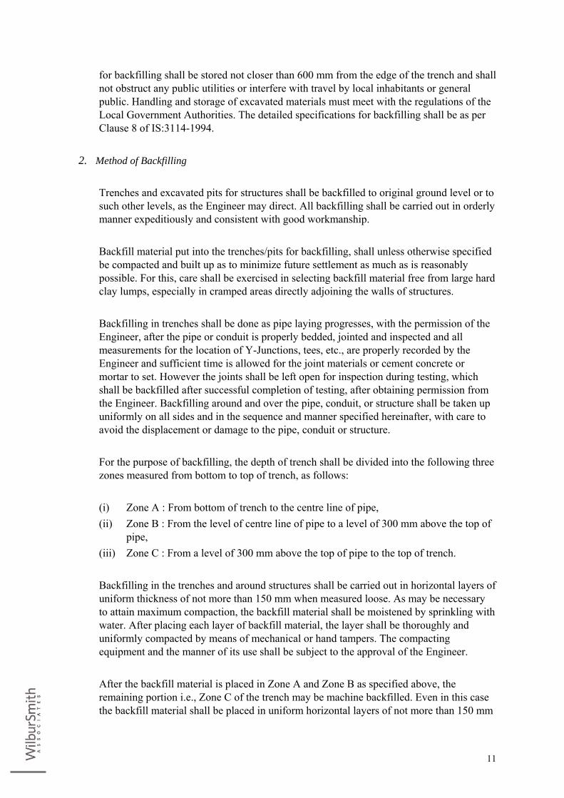
for backfilling shall be stored not closer than 600 mm from the edge of the trench and shall not obstruct any public utilities or interfere with travel by local inhabitants or general public. Handling and storage of excavated materials must meet with the regulations of the Local Government Authorities. The detailed specifications for backfilling shall be as per Clause 8 of IS:3114-1994.
2. Method of Backfilling
Trenches and excavated pits for structures shall be backfilled to original ground level or to
such other levels, as the Engineer may direct. All backfilling shall be carried out in orderly manner expeditiously and consistent with good workmanship.
Backfill material put into the trenches/pits for backfilling, shall unless otherwise specified
be compacted and built up as to minimize future settlement as much as is reasonably possible. For this, care shall be exercised in selecting backfill material free from large hard clay lumps, especially in cramped areas directly adjoining the walls of structures.
Backfilling in trenches shall be done as pipe laying progresses, with the permission of the
Engineer, after the pipe or conduit is properly bedded, jointed and inspected and all measurements for the location of Y-Junctions, tees, etc., are properly recorded by the Engineer and sufficient time is allowed for the joint materials or cement concrete or mortar to set. However the joints shall be left open for inspection during testing, which shall be backfilled after successful completion of testing, after obtaining permission from the Engineer. Backfilling around and over the pipe, conduit, or structure shall be taken up uniformly on all sides and in the sequence and manner specified hereinafter, with care to avoid the displacement or damage to the pipe, conduit or structure.
For the purpose of backfilling, the depth of trench shall be divided into the following three
zones measured from bottom to top of trench, as follows:
(i) Zone A : From bottom of trench to the centre line of pipe, (ii) Zone B : From the level of centre line of pipe to a level of 300 mm above the top of
pipe, (iii) Zone C : From a level of 300 mm above the top of pipe to the top of trench.
Backfilling in the trenches and around structures shall be carried out in horizontal layers of
uniform thickness of not more than 150 mm when measured loose. As may be necessary to attain maximum compaction, the backfill material shall be moistened by sprinkling with water. After placing each layer of backfill material, the layer shall be thoroughly and uniformly compacted by means of mechanical or hand tampers. The compacting equipment and the manner of its use shall be subject to the approval of the Engineer.
After the backfill material is placed in Zone A and Zone B as specified above, the
remaining portion i.e., Zone C of the trench may be machine backfilled. Even in this case the backfill material shall be placed in uniform horizontal layers of not more than 150 mm
12
thickness. Small pebbles of size less that 50 mm, if any, shall be so distributed throughout the mass, that all interstices are solidly filled with fine material. The backfill material shall be tamped with mechanical tamping equipment, after moistening the backfill by sprinkling with water to obtain maximum compaction.
Machine backfill shall be so conducted that the material deposited in the trench shall not
fall directly on top of the pipe from such a height as might result in damage to the pipe joints or alignment.
If the trench is subjected to conditions, which might cause flotation of the pipe before
sufficient backfill has been placed, the Contractor shall take the necessary precautions to prevent floatation of the pipe, conduit or structure.
Before final acceptance of the work, additional tamped earth shall be added to restore the
settled trench surface to the required level of the adjacent earth surface or to the base of crushed rock wearing surface or to the finished earth base.
If from the excavated spoil, enough backfill material is not available, imported, selected
and approved backfill material from the borrow pits is required to be placed for backfill, on approval of the Engineer. Backfilling of trenches where the excavation is in the rock shall be with the surplus soft soil, with all lead and lift.
T. Refilling of Trenches of Pipe line:- In execution of this item following work is included.
(i) The available excavated stuff shall be laid in layers of 15 cms to 20 cm. Each layer shall be watered and compacted before the upper layer is laid, till the required level is reached.
(ii) First two layers of 15 cm to 20 cm shall be free from stones or chips or any harmful material to protect the pipe from damage.
(iii) Only soil or soft murum shall be used for filling. (iv) Originally filling shall be done 30 to 40 cm above natural ground or road level. (v) Sinking below the road or ground level if noticed till the completion of work. The
contractor shall have to make it level at his cost.
U. Filling Trenches with Stone Dust:- The stone dust shall be got approved from the Engineer-in-charge. So also the work shall
be carried out as per the directives of the Engineer-in-charge. No extra lead or lift shall be payable.
13
V. Restoring Road to their Original Level:- Before excavation of the road, the necessary schedule of work programme shall be
informed to the other Departments of Civic responsibility and to take permission if necessary. This must also be informed to the concerned Traffic Police for better co-ordination between the public and the departments.
(i) It should be noted that part of the work is to be carried out through the City along
the roads, with some crossings. At all such places where the original Road surface is required to be excavated for the purpose of laying mains, restoring of road surfaces to its original, level and grades will have to be done by the contractor.
(ii) The work of restoring the roads shall be done soon after the pipes have been jointed and tested. Full care shall be taken to see that the least inconvenience is caused to the normal traffic on the roads and all rules In this regard are rigorously followed.
(iii) All damages to the existing structures in pipe alignment shall be made good by the contractor in proper time and manner without extra claim.
(iv) This item includes 30 cms soling. Murrum bindage 40 mm size metal. 25 mm thick premix bitumen carpet with hot mixed seal coat including all material and labour, required for tar / Asphalt roads. The contractor shall obtain necessary permission from respective authority at their cost.
(v) For C.C. Road the item includes 30 cms thick soling and providing and laying PCC / RCC M-200 of thickness of original layer or 200 mm which ever is more.
(vi) If the restoration of the road/ footpath is not made good within 7 days after excavation (laying of pipeline or valve or specials etc) such restorations will be got done by the Engineer at the risk and cost of the Contractor besides the penalty under the clause 12.14.1 of chapter 2.
(vii) The restoration in case of construction of valve chambers must be completed within 20 days after the earthwork excavation commenced.
(viii) If the surplus excavated stuff is not disposed off to the place directed within the stipulated period of 3 days after the restoration or within 10 days after earthwork excavation whichever is earlier, appropriate penalty will be levied and such surplus earth will be got removed through any other Contractor at his risk & cost (besides the penalty).
W. Disposal of Surplus Excavated Material The excavated material which is in surplus to the requirements after backfilling shall be
removed and spread at places shown by the Engineer, with all lead and lift from the site of work, for which no extra payment shall be made. No surplus or excess material shall be disposed in a stream / channel nor in any place where the pre-construction surface drainage may have to be provided, without written permission of the Engineer.

14
3. DETAILED SPECIFICATIONS FOR PIPE LINE WORKS The manufacture, supply, laying, jointing testing and commissioning of pipes used for raw
water, pure water main shall generally conform to specifications mentioned herein. Any additions and/ or modifications specified in this Chapter shall also be followed. For procurement of any material/ equipment/ instruments/ plant etc shall be from reputed makes subject to prior approval from Engineer in charge or Employer duly relevant certificates to substantiate their reputation/credentials.
A. DUCTILE IRON PIPES The DUCTILE IRON pipes shall be manufactured for Class K-7 (working pressure)
confirming to IS 8329/2000 with internal Cement Mortar Lining of smooth finish confirming to IS 4179 with its latest Amendments.
1. Manufacture of DI pipes
Supply of K-7 Class Socket and Spigot Centrifugally Cast (Spun) Ductile Iron Pressure
Pipes conforming to IS 8329- 2000 with ISI mark in standard working lengths of 4.50 mtrs, 5.00 mtrs, 5.5 mtrs & 6.00 mtrs with Cement Mortor Lining inside the pipes and outside bitumen coating conforming to ISO 4179 including suitable (Push on) Rubber Gasket jointing as indicated below. The rubber gaskets also should conform to IS 5382 and its latest amendments and should be tested as laid down in IS 12820 -1989.
2. Laying & jointing of DI pipes
The pipes should be conveyed to worksite, rolled, lowering into the trenches, laying true to
line, leveling with perfect linking at joints using rubber gaskets confirming to relevant IS including cleaning the socket, spigot ends with soap solution and applying soap solution to the spigot and socket ends before insertion of rubber gaskets, jacking and fixing in perfect condition. The pipes should hydraulically tested as per relevant IS. The bidder shall make his own arrangements for procurement of water for testing purposes.
3. Field Hydrostatic Testing of DI Pipes
After laying and jointing of DI pipes the field hydraulic testing has to be carried as per IS
8329 – 2000 and its latest amendments. The pipes or fittings which are found defective shall be replaced and joints found leaking shall be redone without any extra payment. The water and any other equipment required for field hydraulic testing shall be arranged by contractor. The water used for testing shall be of approved quality.
15
4. D.I Specials Supply of DI Specials with ISI Mark conforming to IS 9523/2000 suitable for jointing
200mm to 900mm dia DI Pipes. The pipes and fittings shall be coated for rust prevention as described below:
(i) External Coating Bituminous paint as per Annexure `C’ of IS 8329-2000 / IS 9523-2000 (ii) Internal Lining ` Portland cement (with or without additives) mortar as per Annexure - `B’ of IS 8329–2000
/ IS 9523-2000 (iii) Provision of Thrust Pad - (from DN 80 to DN 100): Thrust pad has to be provided on bends of 90 & 45 deg. for sizes 80 & 100. Bends face the
maximum surge pressure in any pipeline and tend to turn when pressure is applied. The thrust pad provides more surface area for the thrust block (made of concrete) to grip the fitting.
(iv) Provision of Lifting Loops Lifting loops have to be provided on fittings from DN 400 & above this enables easy
lifting of the fitting from the truck to the trench. These loops have been computer aligned & placed at the "centre of gravity" point(s) of each fitting. During lifting the fitting remains stationary (doosent oscillate) also enabling alignment (which is critical for higher dia fittings) with the pipe during placement of fitting in the trench.
(v) Provision of Side Lugs Each socket fitting is to be provided with two side lugs. This lug is available across all
sizes and all type of socket fittings. This enables fastening of wire rope & offers a firm grip for pulling machines while laying and jointing. This can be used to either push the pipe on the fitting or the fitting on the pipe. Without the lugs, the wire rope tied on the socket mouth tends to slip because of lack of any firm support. While the provision of side lugs speeds up laying & jointing considerably, many contractors use a crowbar with the lug to keep the fitting firmly in place while jointing.
16
B. M.S. PIPES
1. Manufacture of MS pipes Manufacturing, providing, transporting, rolling, lowering, laying and jointing, testing,
commissioning of Spirally welded SAW (submerged arc welded)/ ERW pipes (Fe-410 grade) conforming to IS : 3589-2001 with latest amendments including perfect linking and welding of joints to correct position including cost and conveyance of pipes and materials with all lead and lifts, cost of all labour and giving satisfactory hydraulic test as per IS : 3589-2001 with latest amendments for test pressure and working pressure both at factory and site etc. complete as per detailed specifications with inside CM 1:1.5 lining of minimum 10mm thick up to 610 mm OD and minimum 12 mm thick beyond 610 mm OD and outside minimum 25 mm thick coating in CM 1:3 over 50 mm x 50 mm weld mesh of 13 gauge, including loading and unloading of pipes for the following diameters and specified thickness of plate as noted below, including bailing out of water wherever necessary with all lead and lift etc., Complete. The rates are inclusive of all taxes and including excise duty.
No negative tolerance in respect of thickness is permissible for MS pipes (ERW pipes,
SAW & Seamless pipes) and MS specials. Each pipe MS shall be in lengths of 4 m to 12 mtrs based on availability, ease in handling,
transportation & laying. The surfaces of the MS pipe shall be cleaned thoroughly before any lining or coating is
given. The internal cement mortar lining of 10mm thick up to 610mm dia OD and minimum
12mm thick beyond 610 mm dia OD in CM 1:1.5 (by weight) as detailed in IS 3589/2001 with latest amendments for the MS pipes should have smooth finish.
The MS pipes should be hydraulically tested and should be capable of withstanding the
maximum test pressure of two times the working pressure at site.
2. Internal Lining The Cement mortar and Cement concrete used for pipes and specials, shall confirm to the
specifications mentioned in the chapter 10 of standard specifications. The maximum size of the aggregate shall be 1/3rd the thickness of concrete cover. The concrete mix shall have a minimum Cement content of 450 Kg/m3 and minimum characteristic compressive strength of 25 N/mm2 at 28 days. The cement mortar shall have a minimum cement content of 600 Kgs/m3 characteristic compressive strength of 25 N/mm2 at 28 days.
17
3. External Coating
The cement mortar coating is applied on MS pipe using either by wire brush/rubber brush
coating method. The pipe is rotated in a lathe type machine which turns and traverses the pipe. The weld mesh of 50x50mx13mm gauge is wrapped on MS pipe with spacing between pipe weld mesh. Prior to coating cement slurry is applied over the pipe to create alkaline surroundings around the pipe. A stream of premixed cement mortar 1:3 is then shot on to the pipe ejection between high speed counter rotating wheels in contact. Compaction is by impact. Turning and traverse speeds of the pipe make a coat of the minimum thickness 25mm. The ends of the mortar are trimmed to shape. The coated pipe is then cured either by immersion in water or by spraying or by stream or a combination. By this coating process, MS pipe is adequately protected against corrosion. The permeability results shall be as per revised IS 3589/2001 with latest amendments.
4. Laying of MS pipes
The pipes should be conveyed to worksite, rolling, lowering into the trenches, laying true
to line & level and perfect linking at joints and testing and commissioning including loading and unloading at both destination and cuts of pipes wherever necessary including jointing of MS pipes by welding confirming to IS 3589-2001. Pipes shall be laid underground with a minimum earth cover of 1 m. pipes shall be laid in sections of 500 m each. Laying of pipes shall be as per clause 15, Section 10, Standard specifications for procurement of project works. All pipes, fittings and material shall be tested and approved by the Engineer before being laid. Any pipes, fittings or material placed before they are tested and approved shall be removed and replaced with tested and approved material. The pipes shall be hydraulically tested at two times the working pressure. After laying of pipes 5% of the weld joints shall be subjected to Ultrasonic test as per IS:4260 with latest amendments before conducting the hydraulic testing. The bidder shall make his own arrangements for procurement of water for testing purposes.
5. Fabrication of specials
Specials shall be made from the steel of same grade as that of pipe. The thickness of plate
used for specials shall be minimum 8mm. The flanges used for specials shall conform to IS 7322-1985 / 1538-1993 / ANSI standards / DIN standards with latest amendments or equivalent standards. The steel used for making specials shall conform to IS:2062. Flange drilling shall conform to relevant IS codes (IS 5318), Flange drilling shall be suitable for mating with the connecting element. Stiffener rings used for manufacturing specials shall be 8 mm thick. Cement mortar (1:3) 25mm thick shall be used for external coating of specials. In coating, specials shall be provided with wire mesh reinforcement of 50mm x 50mm x 13 mm wire gauge. The inside lining shall be done with two coats of food grade epoxy painting of approved make with each coat 250 microns thick (after dry) over one coat of food grade epoxy primer of approved make with minimum of 50 microns thick (after dry).
18
6. Hydrostatic Testing after manufacturing
After manufacturing the pipes before giving any lining or coating, each pipe section shall
be given a hydrostatic test at factory, in accordance with IS 3589/2001, at two times the working pressure, Hydrostatic testing should confirm to IS 8329/2000.
C. HDPE PIPES These specifications are for pipes of diameters 90 mm to 630 mm. Providing and supplying in standard length ISI mark High Density Polyethylene(HDPE)
pipes suitable for potable water as per IS specification 4984/1995. The item shall be covering manufacturing, supplying and delivery of HDPE pipes having
material grade PE100 bearing IS4984/1995 and its latest version or amendments. The HDPE pipes shall be supplied in standard length or as specified herein.
1. Grade of Material
Raw material used to manufacture the HDPE pipes shall be virgin compounded or Natural
black PE 100 resin confirming to IS4984:1995, IS7328:1992 and ISO4427:1996. The resin proposed to be used for manufacturing of the pipes should also comply with the following norms as per ISO 9080:1992:
(i) The resin should have been certified by the an independent laboratory of
international repute for having passed 10,000 hour long term hydrostatic strength (LTHS) test extrapolated to 50 years to show that the resin has a minimum MRS of over 10MPa. Internal certificate of any resin manufacturer will not be acceptable.
(ii) Certificate for having passed the full scale rapid crack propagation test as per ISO 13478.
(iii) The resin grade for PE 100 shall be 46GP003.
2. Quality assurance certificate Quality assurance certificate as above for the raw material proposed to be used for the
project, from one of the certifying agencies such as Bodycoat or Slevan or Advantica or Reliance India any other internationally reputed organization shall be submitted along with the bid. The bidder should submit the above raw material certificates along with his bid in the first cover.

19
3. Pressure Rating
The pressure rating of HDPE pipes and specials shall be of PN 6 confirming to clause 3.3
of IS 4984.
4. Colour of pipes The Colour of the HDPE pipe shall be confirming to clause 4 of IS4984:1995 or clause
3.1.2, 3.1.3 and 3.2 of ISO4427:1996.
5. Reworked material As per the provision of clause 5.4 of IS4984:1995, addition of not more than 10 percent of
the manufacturer’s own reworked material resulting from the manufacture of pipes is permissible. No other reworked or recycled material shall be used. The material to be used shall be clean and should be derived from the same resin as used for the relevant production.
6. Dimensions
The pipe dimensions shall be as per latest revisions and amendment of Clause 6 of
IS4984:1995. The pipes up to diameters 110mm shall be supplied in coils of 100m length. The coils shall be as per the provisions of clause 6.5 of IS4984:1995. Pipe beyond 110mm shall be supplied in straight lengths of minimum 6m to 12m as per Engineers instructions.
The internal diameter, wall thickness, length and other dimensions of pipes shall be as per
relevant tables of IS: 4984 for different class of pipes. Each pipe shall be of uniform thickness throughout its length. The wall thickness of the PE100, PN 6 pipes shall be as per the table given below:
Nominal Dia of HDPE Pipe (mm) Wall Thickness (mm)
Minimum Maximum
63 2.9 3.4
75 3.5 4.1
110 5.0 5.7
160 7.3 8.3
200 9.1 10.3
315 14.4 16.1
400 18.2 21.2
The dimension tolerances shall be as per IS: 4984.
20
7. Performance requirements
The pipe supplied should have passed the acceptance tests as per clause 9.2 of
IS4984:1995. The manufacturer should provide the test certificates for the tests conducted, as required in clause 9.2 of IS4984:1995 along with the supply of pipes. These tests can be performed in the in-house laboratory of the pipe manufacturer or at an approved laboratory. The Employer will fix the third party for inspection of pipes at factory.
8. Marking
As per the provisions of clause 10 of IS4984:1995, each straight length of the pipe shall be
clearly marked in inedible ink/ paint on either end and for coils at every 5m the following information:
i. The manufacturer’s name and/ trade mark ii. Designation of the pipe as per IS iii. Lot number/ Batch number iv. Employer’s mark as “PHED” only.
9. BIS License
The pipe manufacturer who is going to supply the pipe for the project has to have a valid
BIS license to do so for the kind of pipes required for this project. The bidders shall include this valid license along with their bid.
10. Fittings / Specials
All HDPE fittings/ specials shall be moulded for lower diameter upto 200mm dia and
fabricated for other diameter in accordance with IS: 8360 (Part I & III). PE Injection moulded fittings shall be as per IS: 8008 (Part I to IX). All fittings/specials shall be fabricated or injection moulded at factory only. No fabrication or moulding will be allowed at site, unless specifically permitted by the Engineer.
Fittings will be electro-fusion welded on to the pipes or other fittings by use of heat fusion. Bends. HDPE bends shall be plain square ended conforming to IS: 8360 Part I & III
Specifications. Bends may be fabricated by jointing several small sections of pipes to reach the required angle.
Tees. HDPE Tees shall be plain square ended conforming to IS: 8360 Part I & II
Specifications. Tees may be equal tees or reduced take off tees. Tees may be moulded or fabricated from pipes elements.
21
Reducers. HDPE Reducers shall be plain square ended conforming to IS: 8008 Part I &
VII Specifications. Reducer must be moulded. Flanged HDPE Pipe Ends. HDPE Stub ends shall be square ended conforming to IS: 8008
Part I & VII Specifications. Stub ends will be welded on the pipe. Flange will be of slip on flange type as described below.
Slip-On Flanges. Slip-on flanges shall be metallic flanges covered by epoxy coating or
plastic powder coating. Slip-on-flanges shall be conforming to standard mating relevant flange of valves, pipes etc. Nominal pressure rating of flanges will be PN 10.
11. Procedure
Jointing between HDPE pipes and specials shall be done as per the latest IS: 7634 part II.
Method of jointing between the pipes to pipes and pipes to specials shall be with electro fusion welding wherever necessary using automatic or semi automatic, hydraulically operated, superior quality electro fusion machines which will ensure good quality electrofusion welding of HDPE pipes. If approved by the Engineer, jointing with PP compression fittings may be carried out for smaller diameters of PE pipes (up to 110mm).
12. Butt Jointing
Electro fusion butt joint can be provided during continuous laying of HDPE pipeline
conforming to relevant IS Standards. The butt joint shall not be allowed in case of joining two ends already laid & in such case only electro fusion with fittings is allowed.
With a clean dry cloth wipe the inside and outside surfaces of the two pipe ends to be
joined to remove dirt, moisture and foreign materials. It is important that the ends protruding past the clamp jaws be absolutely clean and free of any kind of contaminations.
Install pipe in the welding machine clamps. Ends should extend approximately one inch
past alignment clamps for facing. Check alignment and adjust as required to get perfect alignment of the meeting surfaces.
Pipe ends should be perfectly faced by facer or square-cut with appropriate tools meant for
the same. Remove any burr on the meeting faced / square-cut ends by a knife. Do not touch the meeting pipe ends by hand, which may contaminate the meeting surfaces due to dirt or perspiration or body oil.
Bring the two pipe ends together after facing, to see the alignment once again and ensure
the alignment is perfect. Separate the two pipe ends and insert the heater plate between the two pipe ends. Bring the

22
movable pipe section against the heater plate until both pipe-ends are in full and firm contact with the heater plate.
As soon as the pipe ends are firmly in contact with the heater plate, immediately remove
the pressure given to the clamp to remove the pressure on pipe ends on heater plate. If the pressure on the pipe is maintained during heating, the melt will be squeezed away from the pipe ends and create a concave effect in the pipe ends and this will weaken the joint.
Heat the pipe ends until properly sized melt bead are formed on both pipe ends. As the
pipe ends melt against the heater plate during the heating period, the molten plastic will swell and form melt beads around the pipe ends. The melt beads should be the same size on both ends and uniformly sized all the way around.
The butt fusion temperature is normally situated between 2000C to 2350C depending on
the variable factors.
Pipe size Approximate one side melt bead width
Less than 90 mm OD pipes 1.60 mm
90 mm OD to 180 mm OD pipes 3.20 mm
200 mm to 250 mm OD pipes 4.75 mm
280 mm to 630 mm OD pipes 6.25 mm
Please note the meld bead width values given above are indicative only and depending on
wall thickness of the pipe, the material grade, production type, temperature of the heater plate and the applied fusion-cycle, the melt swell bead width may vary.
After melting has been completed as described above, separate the pipe ends, just enough
to remove the heater. Quickly observe the parts to be joined to ensure sufficient and uniform melting patterns. Then quickly bring the pipe ends together with the fusion jointing pressure. Join the pipe ends within a time of (3+0.0dn) seconds with a maximum 6 seconds for diameters upto & including dn 250 mm and a maximum of 12 seconds for diameters above dn 250 mm.
To ensure a good quality joint, it should have a smooth symmetrical bead shape around the
entire pipe circumference as shown in the following figure A. The bead depression "A" shall not extend below the pipe surface.
If the molten plastic sticks to the heater, do not continue with jointing. Allow the pipe ends
to cool and start all over again from the beginning with refacing / square cutting. Fusion jointing pressure would vary with pipe size, wall thickness and material grade.

23
The force applied will cause each bead to roll back on to the pipe. Insufficient or excessive roll back is one indication of a faulty joint Fig. `B'.
While maintaining the pressure used in making joints, allow the joints to cool naturally for
30 to 90 seconds per inch of pipe diameter before removing from the clamps. Heavier walled (lower SDR) pipes require longer cooling time. However, the cooling time will vary depending on the prevailing climatic / environmental conditions.
On examining if the joint appears faulty, cut open the joint and start all over again from
the beginning. On satisfactory appearance, remove fused pipe from the welding clams. Allow the joint to
cool under no pressure at least for 20 minutes after removal from welding clamps before subjecting the joint to testing, bending or backfilling stresses.
13. Workshop
The Contractor has to establish a workshop for jointing group of HDPE specials by means
of electro fusion welding. Two or more PE specials coming at one place (like HDPE Tee, Reducer, Flanged end etc.,) shall be jointed at workshop and transported to the site of works for final installation with proposed PE pipelines. In no case, jointing of two or more PE specials in one place, at site will be allowed.
14. Field Works
After visual inspection and approval of the welded PE specials assembly by the Engineer,
the group of PE specials welded at workshop shall be transported to site of works for installation with the proposed PE pipes or valves etc., by means of electro fusion or slip-on flanged joints.
15. Field Hydro static testing of HDPE pipes
After laying and jointing of HDPE pipes and specials, the hydraulic testing shall be carried
out at 1.5 times the working pressure. The pipes or fittings which are found defective shall be replaced and joints found leaking shall be redone without any extra payment. The water and any other equipment required for field hydraulic testing shall be arranged by contractor. The water used for testing shall be of approved quality.
24
D. Glass Fiber Reinforced Plastic (GRP) Pipes, Fittings And Specials
1. Scope This section describes detailed specification for manufacture, supply, fabrication,
installation/ erection and testing of Glass reinforced polyester/plastic (GRP) pressure pipeline, bends, reducers etc. complete. The fabrication requires proper equipment and necessary certifications for manufacturing. The fabricator must have in its shop satisfactory facility for edge preparation and grinding, hydraulic test and other required tests as per relevant codes.
2. Codes, Standards and Manuals
All pipes, joints and fittings supplied under this specification shall fully meet the
requirements of at least one the following standards, depending on the use to which the pipes are intended to be put. Other standards are also mentioned for reference as needed.
(i) IS 12709:1994. Specification for glass fiber reinforced plastic (GRP) pipes joints
and fittings for use for potable water supply. (ii) IS 14402 : 1996 Specification for GRP pipes joints and fitting for sewerage,
industrial waste and water (other than portable). (iii) IS 13916:1994. Code of practice for installation of glass fiber reinforced plastic
(GRP) piping system. Additional details are available in the following standards which may be referred to when
and if needed: (i) AWWA C 950, AWWA Standard for Fiber glass pressure pipe. (ii) AWWA Manual M45, Fiber glass Pipe Design. (iii) ASTM D3517. Standard Specification for fiberglass (Glass fiber reinforced
Thermosetting Resin) Pressure pipe in the case of pressure pipes. (iv) ASTM D3262, Standard specification for fiberglass (Glass fiber reinforced
Thermosetting Resin) Sewer pipe in the case of gravity sewer pipes. (v) ASTM D3754, Standard specification for fiberglass (Glass fiber reinforced
Thermosetting Resin) Sewer and Industrial Pressure pipe. (vi) ASTM D4161. Standard specification for fiberglass (Glass fiber reinforced
Thermosetting Resin) Pipe joints using Flexible Elastomeric seals. (vii) ASTMD578-00. Standard specification for Glass Fiber Strands.
25
3. Product Description
The Manufacturer should manufacture GRP Pipes using either dual helical Continuous
Filament Winding process or using the continuously advancing mandrel process and should be capable of manufacturing specials. The manufacturer shall arrange for 3rd party inspection at their works for pipe diameters, pressure rating and stiffness class offered and at the minimum and have testing facilities at least for the compulsory tests specified in the relevant BIS Standard.
Materials Resin Systems.The manufacturer will use only resin systems suited to the application.
Specifically, for potable water applications, styrene monomer should be within the prescribed limits in the internal gel coat (inner lining) as the same comes in direct contact with water.
Glass Reinforcements. The reinforcing glass fibers, used in the manufacture of the
components shall be of E Glass or better (eg boron free E-CR (Electrical and Corrosion Resistant) glass filaments, suitably treated with binder and sizing compatible with impregnating resins.
Fillers/fortifiers. Silica sand or other suitable materials may be used as fillers in the
laminates to provide the requisite stiffness. Elastomeric Sealing Rings. Elastomeric Sealing rings must be supplied by recognized,
acceptable quality manufacturers. The elastomeric compound used must be compatible with the end use environment eg EPDM or SBR)
Manufacture and Construction Pipes. The pipes shall be supplied in accordance with the diameters and tolerances
specified in respective IS code. They shall be manufactured by a controlled reproducible process using the materials to result in a corrosion resistant product with Composite structure to meet the operating conditions for the project.
Couplings.The pipe may preferably have a spigot and bell jointing system till 1000 mm Ø
to help quicker laying and water tightness. Alternatively, the pipes may be field connected with GRP sleeve coupling that utilizes elastomeric Sealing rings to maintain joint water tightness. They must meet the Performance requirements of ASTM D 4161.
Fittings. Flanges bends, reducers Tees wyes and other fittings shall, when installed be
capable of withstanding all operating conditions of the project. They may be contact molded or manufactured from mitered sections of pipe joined by glass fiber reinforced resin overlays. Fittings to be used inside chambers, if any, shall be clearly identified to the
26
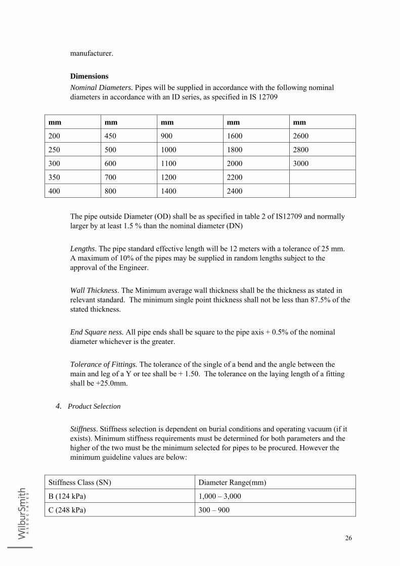
manufacturer. Dimensions Nominal Diameters. Pipes will be supplied in accordance with the following nominal
diameters in accordance with an ID series, as specified in IS 12709
mm mm mm mm mm
200 450 900 1600 2600
250 500 1000 1800 2800
300 600 1100 2000 3000
350 700 1200 2200
400 800 1400 2400
The pipe outside Diameter (OD) shall be as specified in table 2 of IS12709 and normally
larger by at least 1.5 % than the nominal diameter (DN) Lengths. The pipe standard effective length will be 12 meters with a tolerance of 25 mm.
A maximum of 10% of the pipes may be supplied in random lengths subject to the approval of the Engineer.
Wall Thickness. The Minimum average wall thickness shall be the thickness as stated in
relevant standard. The minimum single point thickness shall not be less than 87.5% of the stated thickness.
End Square ness. All pipe ends shall be square to the pipe axis + 0.5% of the nominal
diameter whichever is the greater. Tolerance of Fittings. The tolerance of the single of a bend and the angle between the
main and leg of a Y or tee shall be + 1.50. The tolerance on the laying length of a fitting shall be +25.0mm.
4. Product Selection
Stiffness. Stiffness selection is dependent on burial conditions and operating vacuum (if it
exists). Minimum stiffness requirements must be determined for both parameters and the higher of the two must be the minimum selected for pipes to be procured. However the minimum guideline values are below:
Stiffness Class (SN) Diameter Range(mm)
B (124 kPa) 1,000 – 3,000
C (248 kPa) 300 – 900
27
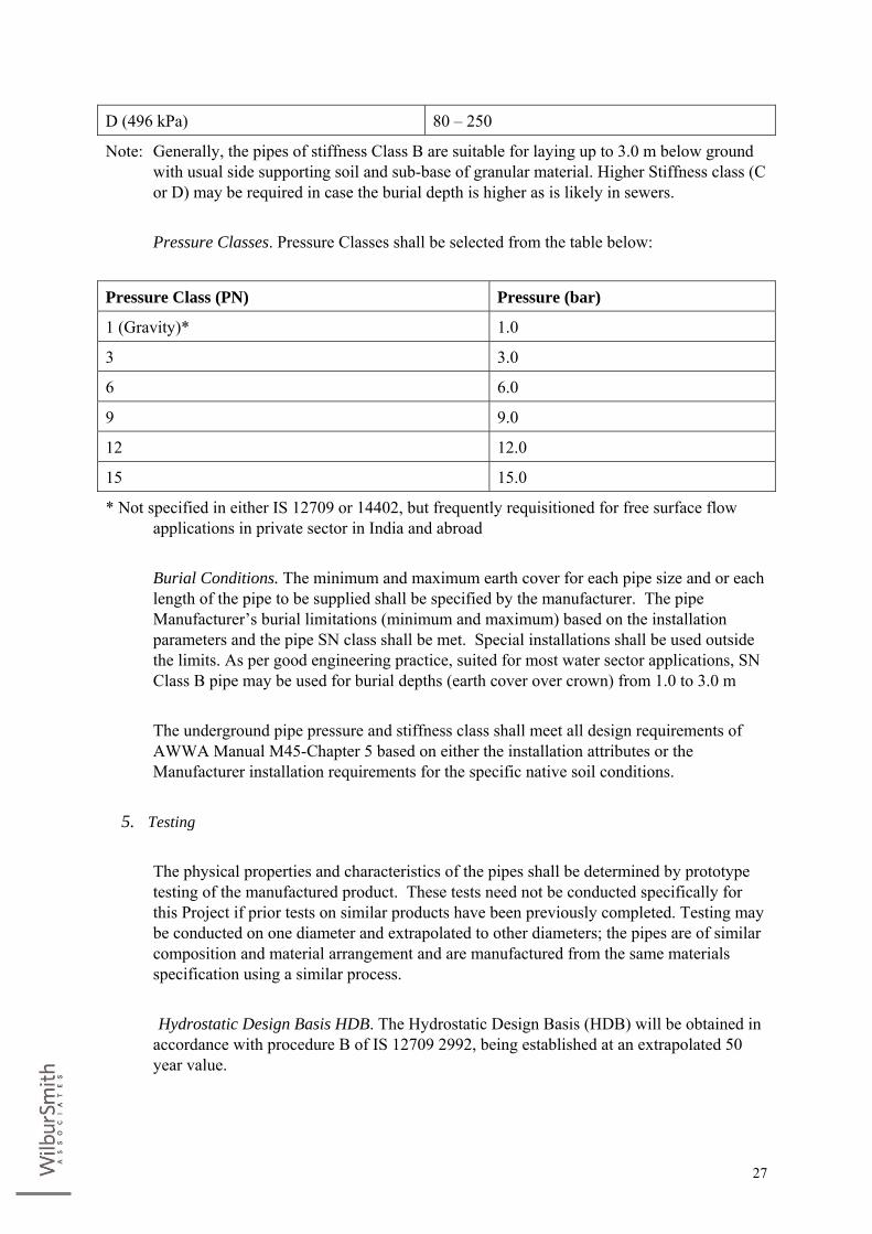
D (496 kPa) 80 – 250
Note: Generally, the pipes of stiffness Class B are suitable for laying up to 3.0 m below ground with usual side supporting soil and sub-base of granular material. Higher Stiffness class (C or D) may be required in case the burial depth is higher as is likely in sewers.
Pressure Classes. Pressure Classes shall be selected from the table below:
Pressure Class (PN) Pressure (bar)
1 (Gravity)* 1.0
3 3.0
6 6.0
9 9.0
12 12.0
15 15.0
* Not specified in either IS 12709 or 14402, but frequently requisitioned for free surface flow applications in private sector in India and abroad
Burial Conditions. The minimum and maximum earth cover for each pipe size and or each
length of the pipe to be supplied shall be specified by the manufacturer. The pipe Manufacturer’s burial limitations (minimum and maximum) based on the installation parameters and the pipe SN class shall be met. Special installations shall be used outside the limits. As per good engineering practice, suited for most water sector applications, SN Class B pipe may be used for burial depths (earth cover over crown) from 1.0 to 3.0 m
The underground pipe pressure and stiffness class shall meet all design requirements of
AWWA Manual M45-Chapter 5 based on either the installation attributes or the Manufacturer installation requirements for the specific native soil conditions.
5. Testing
The physical properties and characteristics of the pipes shall be determined by prototype
testing of the manufactured product. These tests need not be conducted specifically for this Project if prior tests on similar products have been previously completed. Testing may be conducted on one diameter and extrapolated to other diameters; the pipes are of similar composition and material arrangement and are manufactured from the same materials specification using a similar process.
Hydrostatic Design Basis HDB. The Hydrostatic Design Basis (HDB) will be obtained in
accordance with procedure B of IS 12709 2992, being established at an extrapolated 50 year value.
28
Long Term Ring Bending Strength. The Long-Term Ring Bending Strength (Sb) will be
determined in accordance with AWWA C 950 for water projects or ASTM D3262 section 6.3 for sanitary sewer projects.
Joints. Coupling joints shall be qualified as per the tests of section 7 of ASTM D 4161.
6. Product Use Deflection. The maximum allowable long-term deflection shall be 5%. These values shall
apply to all stiffness classes. Operating Temperatures. The maximum allowable operating temperature of the pipes
shall be 500C. The minimum allowable operating temperature of the pipes shall be 40C.
7. Installation Procedures Standard Installation Procedures. GRP pipes shall be installed in accordance with the
installation parameters as specified in accordance with IS 13916: 1994 amended up to date and keeping in view Manufacturer’s installation instructions.
Additional Procedures. Additional installation procedures like pipe or fitting concrete
encasement pouring, pipe flexibility at rigid connections. Pipe end reinforcement, field closure sections, pipe casing procedures, use of concrete cover slabs, etc. shall be done as per the Manufacturer installation instructions or his written advice.
8. Quality Assurance & Qualty Control
Quality control testing shall be conducted in accordance with this specification and in
accordance with relevant test method specified in IS 12709 or IS 14402. . These tests shall as a minimum cover:
i. Pipe stiffness ii. Hydrostatic testing (as agreed with purchaser) iii. Axial tensile and hoop Load capacities iv. Critical dimensions v. Visual acceptance
Barcol hardness may be checked to ascertain proper curing of the pipes (if the surface of
the pipes is found to be tacky) in accordance with ASTM D2483 Adequate records must be kept by the Manufacturer. Such reports will be readily
available for inspection by the customer or his Engineer or Representative. The Customer
29
or his Representative may witness quality control tests. Pipe Stiffness. Samples of pipe shall be tested for compliance with pipe stiffness in
accordance with Annex B of IS 12709. The test frequency of pipe ring samples shall be at least one per lot or one per day.
If the one sample fails, it should be re-tested. If it still fails, cut two (2) additional samples
from the lot (from the preceding and the following pipes). If they both pass, then the entire batch except the failed pipe is considered acceptable. If not as above, the pipes must be proven individually acceptable. Testing will be carried out in accordance with ASTM D 2412.
Hydraulic Test. The Manufacturer shall, as agreed upon with the purchaser,
hydrostatically test the pipes to 1.25 times the Design pressure up to 1400 mm diameter and beyond 1400 mm up to the Design pressure.
The pressure class of the pipes will be that specified in Table (as selected in section 4.2).
Any pipe failing to pass this test to be rejected. Rejected pipes may be repaired and re-tested; if they pass, they will then be accepted.
Load Capacity (Hoop and Axial). Tests will be performed accordance to requirements in
IS 12709 to check load capacity (or strength) both in the hoop and axial direction. One of each test shall be made per production lot.
Should samples fail to meet or exceed the stated values for each test. Two additional
samples shall be cut from the preceding and following pipes. If they both pass and the average of all three sets passes, then the entire lot may be considered acceptable.
Critical Dimensions. Pipes will be measured for compliance with critical dimensions as
specified in earlier including diameter, thickness, and squarness and length. Diameter. Checks on diameter will be made at each change of diameter manufactured.
The pipe outside diameter (OD) shall meet the requirement for OD as stated in table 2 of IS 12709.
Thickness. All Pipes will be checked for compliance with thickness stated in section 10.1.
The minimum average thickness and the minimum single point thickness must meet the requirement of cl. 7.4 of IS 12709
If Requirements in regard to thickness alone are not met, the thin pipes may be reinforced
or may be acceptable for another class.

30
End Squareness. Any pipe with stepped ends shall be checked to ensure compliance with
the requirements of c l. 7.3 of IS 12709 /IS 14402 as applicable. Length. All pipes must be measured to ensure compliance with the requirements of cl. 7.2
of IS 12709/ IS 14402 as applicable Visual Acceptance. The pipes shall be free from all defects, including de-laminations,
bubbles, pinholes, cracks, pits, blisters, foreign inclusions, and resin starved areas that, due to their nature, degree or extent, detrimentally affect the strength and serviceability of the pipe. The pipe shall be as uniform as commercially practicable in color, opacity, density and other physical properties.
9. Inspections
The Department or his authorized representative shall be entitled to inspect pipes or
witness the pipe manufacturing and Quality Control (QC) tests. Such inspection shall in no way relieve the Manufacturer of the responsibility to provide products that comply with applicable standards within this specification.
10. Submittals
The Manufacturer shall include in his offer, in addition to the items specified sufficient
data for the broad evaluation of his proposed pipe. This data shall include, as a minimum, the following specific information.
i. Details of the Proposed pipe thickness and properties ii. Pressure class iii. Stiffness class iv. Details of joints v. Hydrostatic test plan (to be agreed with the purchaser)
4. VALVES
A. General The valves shall be manufactured for the work as per relevant IS specifications and basic
parameters. Required number of suitable valves of Department approved make shall be supplied and fixed as directed by the Engineer-In-charge by the Contractor himself at the locations shown in the drawings.
All valves shall be fixed at the required locations with necessary bolts, nuts, washers,
gaskets, etc., complete and provided with cement concrete supports.
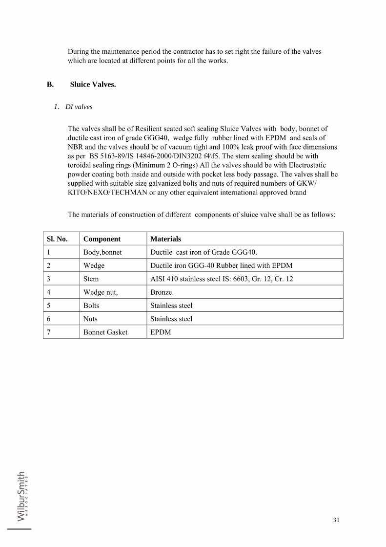
31
During the maintenance period the contractor has to set right the failure of the valves which are located at different points for all the works.
B. Sluice Valves.
1. DI valves The valves shall be of Resilient seated soft sealing Sluice Valves with body, bonnet of
ductile cast iron of grade GGG40, wedge fully rubber lined with EPDM and seals of NBR and the valves should be of vacuum tight and 100% leak proof with face dimensions as per BS 5163-89/IS 14846-2000/DIN3202 f4\f5. The stem sealing should be with toroidal sealing rings (Minimum 2 O-rings) All the valves should be with Electrostatic powder coating both inside and outside with pocket less body passage. The valves shall be supplied with suitable size galvanized bolts and nuts of required numbers of GKW/ KITO/NEXO/TECHMAN or any other equivalent international approved brand
The materials of construction of different components of sluice valve shall be as follows:
Sl. No. Component Materials
1 Body,bonnet Ductile cast iron of Grade GGG40.
2 Wedge Ductile iron GGG-40 Rubber lined with EPDM
3 Stem AISI 410 stainless steel IS: 6603, Gr. 12, Cr. 12
4 Wedge nut, Bronze.
5 Bolts Stainless steel
6 Nuts Stainless steel
7 Bonnet Gasket EPDM

32
Hydro-Static Tests. Each valve shall be subjected to closed and hydrostatic test as follows: Body Test: The body of each sluice valve shall be hydraulically tested to the 1.5 times the
working pressure and the test pressure shall be maintained for a duration of 5 minutes. The valve shall show no sign of leakage under these tests.
Seat Test: The seat shall be tested to 1.00 times the working pressure and the test pressure
shall be maintained for a duration of 2 minutes. The valve shall show no sign of leakage under there tests.
Coating: All the valves are to be electro static powder coated both inside and out side of
GSK quality. The minimum dry thickness of the coating is 250 microns. All the valves are to be compatible for underground installation without valve chamber.
Packing: The valves shall be supplied with the wedge closed, bright parts protected
against rust, valves of small dia meters shall be packed in wooden cases. Valves with smooth finished flanged joint faces shall be suitably protected against damage. Parts liable to injury in transit shall be wrapped with wood-wool or similar material as protection. Hand wheel of valves forwarded shall be removed before dispatch.
Marking: Each valve body shall be cast in raised letter with the following information:
(i) The manufacturers name or trade mark (ii) The nominal pressure of the valve (iii) The size
2. CI Valves
Sluice valves shall generally conform to IS 14846:2000. The valves shall be of rising
spindle type and close in the clockwise direction. The direction of closing shall be marked on the hand wheel.
Materials of Construction of valve components shall be as follows:
S. No
Component Material of construction
Reference to IS Nos.
Grade / Designation
1 Body, Bonnets, Wedge, Dome , stool, cover, stuffing box, gland, thrust plate and cap
Grey cast iron 210 FG 200

33
2 Hand wheel Grey cast iron 210 FG 200
3 Stem Stainless steel 6603 12Cr 13 04Cr 18Ni 10 04Cr 17Ni 12 MO2
4 Wedge nut, shoe, channel Leaded tin Bronze
318 LTB-2
5 Body seat ring, wedge facing ring and bushes
Leaded tin Bronze
318 LTB-2
6 Bolts Stainless steel 6603
7 Nuts Stainless steel 6603
8 Gasket Rubber 638 Type B
9 Gland packing Jute and hemp 5414
10 Gear Cast steel 1030
11 Gear Housing Cast steel 1030 230-450W
12 Pinion and pinion shaft Stainless steel 6603
Hydro Static Tests Each valve shall be subjected to closed and hydrostatic test as follows:
i. Body Test: The body of each sluice valve shall be hydraulically tested to the 1.5 times the working pressure and the test pressure shall be maintained for a duration of 5 minutes. The valve shall show no sign of leakage under these tests.
ii. Seat Test: The seat shall be tested to 1.00 times the working pressure and the test pressure shall be maintained for a duration of 2 minutes. The valve shall show no sign of leakage under these tests.
iii. Coating: All the valves are to be electro static powder coated both inside and out side of GSK quality. The minimum dry thickness of the coating is 250 microns. All the valves are to be compatible for underground installation without valve chamber.
C. Air valves (Tamper Proof) Tamper proof air valves of specified dia shall be provided at the locations shown to release
& admit air at high flow rates from and into the water pipeline while pumping, filling and emptying with design and testing standards of AWWA C512-92 with long life stainless steel float, Zero water leakage. The flanges drilled to IS 1538 or BS 4505.
Sl. No. Description Materials Specification.
1. Body Cast Iron IS: 210 FG 260
2. Float Stainless Stell SS 304

34
3. Nozzle IS: 318 LB2/GM With Rubber
4 Gasket Rubber Neoprene
5 Cover Carbon Steel Plate
6 Stud & Bolts Carbon Steel High tensile
7 Body Cast Iron IS 210 FG 260
8 Float Stainless Steel SS 306
9 Bolts & Nuts Steel MS
10 Nozzle IS 318 LB2 / GM with rubber
11 Cover Cast Iron IS 210 FG260
12 Adaopter Steel MS with O Ring
D. Double Flanged Butterfly Valves Conforming to IS 13095 with ISI Mark Supplying of approved make manually operated self locking type fabricated/cast steel
double flanged butterfly valves - PN 1.6 confirming to /IS:13095/ BS:5155 AWWA:C-504 with flanged ends drilled in accordance with IS:1538 Part VI/IS:6392 table (5)(ii) and (17)IS:6418 table 3,6 and 7/BS:4504/AWWA:C-207 with latest amendments as detailed below for following diameters and types and conveying to worksite, loading, unloading, stacking, and fixing with flanges, etc., complete with all lead and lifts and as directed by Engineer-in-charge, with hand wheel and position indication. The flanges shall be at right angles to the axis of the bore and concentric with bore. The gear box shall have worm and worm wheel design totally closed grease filled and weather proof. There shall be, valve position indicator graduated in degrees of travel to show from full open to full close. The valve shall have drop tight closure, low head loss, uninterrupted disc periphery, renewable face ring(Rubber seal) with horizontal or vertical shaft with good closing characteristic and ease of throttling etc., The valve shall be free from induced vibrations. The valve shall be of single/duo-eccentric seat geometry so as to reduce the disc seal wear and tear. The valves shall be supplied along with the required number of standard make galvanized Bolts and Nuts of GKW/KITO/NEXO/TECHMAN make or any equivalent international approved brand.
Sl. No. Component Material of Construction, Ref. To IS and Grade or
Designation 1 Body Cast Iron : IS 210-Gr-FG 260 2 Body Liner Black Nitrile 3 O' Ring Black Nitrile 4 Disc Cast Iron : IS 210-Gr-FG 260 5 Shaft Stainless Steel 6603:1972 6 Seat Ring / Seat Retaining
Ring Stainless Steel 6603:1972
35
Testing: Each Valve shall be subjected to Hydrostatic testing as per IS 13095 Coating: All coatings / paintings shall be carried out after satisfactory testing of the Valves
as per standard, prior to dispatch.
E. Dual Plate Non Return Valves The design and manufacture of the valves shall comply with all currently applicable
statutes, regulations and safety codes in the locality where the equipments will be installed. Nothing in this specification shall relieve the contractor of his responsibility. The valves shall be confirming to API 594 and API 598. The distance across flanges shall be in accordance to IS:5312 for flanged valves.
1. Design Requirements
The non return valves shall be of dual plate type check valve and provided with soft
seating for clear and cold water. The valves shall be suitable for mounting on horizontal/vertical pipeline. The valves shall be designed for minimum head loss. The valves shall have lugged ends or flat faced flanged ends as specified. The back side of the flanges shall be fully or spot faced. Hydraulic passage shall be designed to avoid cavitations. The valves shall have non slam characteristic during closing. This is to be achieved by suitably designed springs. Direction of flow shall coincide with the flow direction indicated by arrow cast on the valve body.
2. Painting
Valves shall first be given two coats of zinc base primer after completely cleaning the
surface and then it shall be coated with three coats of epoxy paint. The resulting coating shall be uniform and smooth and shall adhere perfectly to the surface. The coating shall not contain any constituent soluble in water or any ingredient which could impart any taste or odor to the water.
3. Tests and Inspection
Valves shall be tested as per relevant Indian standards specification, API 594 and API 598
with latest revisions. Valves shall be offered for visual inspection and dimensional checks. The hydrostatic and water tightness testing shall be witnessed by the Engineer. Valve shall be offered for inspection and following tests will be conducted (before painting) : • Visual inspection with dimensional checks. • Hydrostatic test.
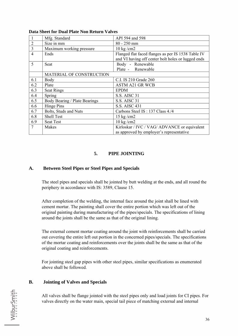
36
Data Sheet for Dual Plate Non Return Valves 1 Mfg. Standard API 594 and 598 2 Size in mm 80 - 250 mm 3 Maximum working pressure 10 kg /cm2 4 Ends Flanged flat faced flanges as per IS 1538 Table IV
and VI having off center bolt holes or lugged ends 5 Seat Body - Renewable
Plate - Renewable MATERIAL OF CONSTRUCTION 6.1 Body C.I. IS 210 Grade 260 6.2 Plate ASTM A21 GR WCB 6.3 Seat Rings EPDM 6.4 Spring S.S. AISC 31 6.5 Body Bearing / Plate Bearings S.S. AISC 31 6.6 Hinge Pins S.S. AISC 431 6.7 Bolts, Studs and Nuts Carbons Steel IS : 137 Class 4./4 6.8 Shell Test 15 kg /cm2 6.9 Seat Test 10 kg /cm2 7 Makes Kirloskar / IVC / VAG/ ADVANCE or equivalent
as approved by employer’s representative
5. PIPE JOINTING
A. Between Steel Pipes or Steel Pipes and Specials The steel pipes and specials shall be jointed by butt welding at the ends, and all round the
periphery in accordance with IS: 3589, Clause 15. After completion of the welding, the internal face around the joint shall be lined with
cement mortar. The painting shall cover the entire portion which was left out of the original painting during manufacturing of the pipes/specials. The specifications of lining around the joints shall be the same as that of the original lining.
The external cement mortar coating around the joint with reinforcements shall be carried
out covering the entire left out portion in the concerned pipes/specials. The specifications of the mortar coating and reinforcements over the joints shall be the same as that of the original coating and reinforcements.
For jointing steel gap pipes with other steel pipes, similar specifications as enumerated
above shall be followed.
B. Jointing of Valves and Specials All valves shall be flange jointed with the steel pipes only and load joints for CI pipes. For
valves directly on the water main, special tail piece of matching external and internal
37
diameter with suitable flange on one end shall be fabricated either at site or at manufacturer's works, and provided with lining and coating as per specifications. For valves to be fitted in the body of the water main, special 'Tee' with flange at the valve end shall be fabricated either at site or at manufacturer's works, and provided with lining and coating as per specifications. The other ends of tail pieces / tees for connecting valves shall be of beveled ends suitable for connecting to the steel pipes by butt welding.
6. PROCESS VALIDATION Process validation for laying pipe shall be done by the contractor before starting such
process. This shall be done to the satisfaction of Engineer in charge.
7. PROTECTION AGAINST FLOATATION DUE TO UPLIFT PRESSURE. The Contractor shall ensure that all structures constructed underground by lowering sub
soil water level, shall be protected against uplift and consequent floatation and tilting. Adequate measures including non stop dewatering shall be taken as per relevant IS codes.
8. CIVIL SPECIFICATIONS The following civil specifications shall be applicable for providing and executing all such
items which are not mentioned in foregoing paras but are necessary to be provided and for the items which are mentioned above but require some elaboration. No extra cost shall be paid for such items.
It should clearly be understood by the Contractors / tendering firms that all civil
specifications mentioned here below shall be treated as part of the technical specifications already mentioned. The specific requirement of different items of work involved in the construction, completion and commissioning of the plant as a whole, shall be provided in accordance with the requirement given in these civil specifications.
A. Site Clearance Before taking up construction, site shall be cleared of all jungles, bushes and unwanted
vegetation growth. After completion of plant, the entire site area shall be cleared of all left over material and debris.
B. Design of structures
1. Materials All materials used in the work shall be subjected to mandatory tests in accordance with
relevant IS codes, and before using them on the worm, the test reports shall be submitted

38
to the Engineer for seeking his permission.
2. Form Work Form work, shuttering, centering, scaffolding etc., shall be of steel plants or plywood,
lined with MS sheets and for scaffolding steel tubulars shall be used. Joints should be sufficiently tied to prevent loss of cement slurry from the concrete. All forms, shuttering shall be leveled, aligned and thoroughly cleaned before they are used for concreting.
Form work shall be removed after specified days of curing with the prior written
permission of the Engineer. The surface of RCC after removal of form work / shuttering shall be smooth, even and without honeycombing or undulations.
3. Finishing of RCC Surfaces
To given an even finish to the concrete surfaces, unless otherwise specified, the outside
faces of walls and inside surfaces of ceiling shall be of form work finish, smoothly rendered and other inside faces shall be finished with cement plaster 20 mm thick in 1:3 cement mortar. All concrete surfaces coming in contact with water shall be provided with cement plaster 20 mm thick in 1:3 cement mortar with approved quality water proofing compound in requisite proportion.
4. Minimum clear cover over Reinforcement
Minimum clear cover over the steel reinforcement shall be conformity with IS:3370 in the
case of water retaining structures. For other structures the clear cover over the reinforcement shall be as per IS:456.
5. Minimum Reinforcement
For water retaining structures, the minimum reinforcement in walls, floors and roofs in
each of the two directions at right angles shall have an area of 0.3 percent of the area of concrete section. For HYSD bars, the above percentage of reinforcement can be reduced by 20%.
For other structures, the minimum reinforcement shall be based on IS:456.
6. Minimum Thickness of RCC The minimum thickness of all RCC members viz., walls, roofs, floors etc., shall not be
less than 150 mm.
7. Tested steel Only tested and approved steel reinforcement shall be used on the work, and the
39
Contractor shall produce the test certificate of the manufacturer to the Engineer. The grade of steel shall be Fe:415 conforming to IS:1786.
8. Cement Concrete
For all water retaining concrete structures, cement concrete mix 1:1.5:3 (M20) grade shall
be used. For all other concrete structures, cement concrete 1:2:4 (M15) grade shall be used unless otherwise specified.
9. Lean Concrete
Lean concrete mix of 1:3:6, 150 mm thick shall be provided under all foundations and
floors of structures.
C. Water for Hydraulic testing The Contractor shall have to make all arrangements for water supply at his own cost for
hydraulic testing pipes and valves. Nothing extra shall be payable for above mentioned hydraulic testing.
D. Water for Drinking and Construction work The Contractor shall have to make all arrangements at his own cost for water fit for
construction purposes and also water fit for drinking purposes as per norms of IS codes and nothing extra will be paid.
E. Power for Construction work and Stand by Diesel Generator Set The Contractor shall make all arrangements at his own cost for providing power supply to
the site of work, site office and for construction activities
F. Surveying Instruments Contractor shall keep at least two accurate leveling instruments at each of the site and shall
be responsible for checking all the levels as per designs before starting the construction, during construction and after completion. The Contractor shall be fully responsible for rectifying any mistake noticed at any time at his own cost.
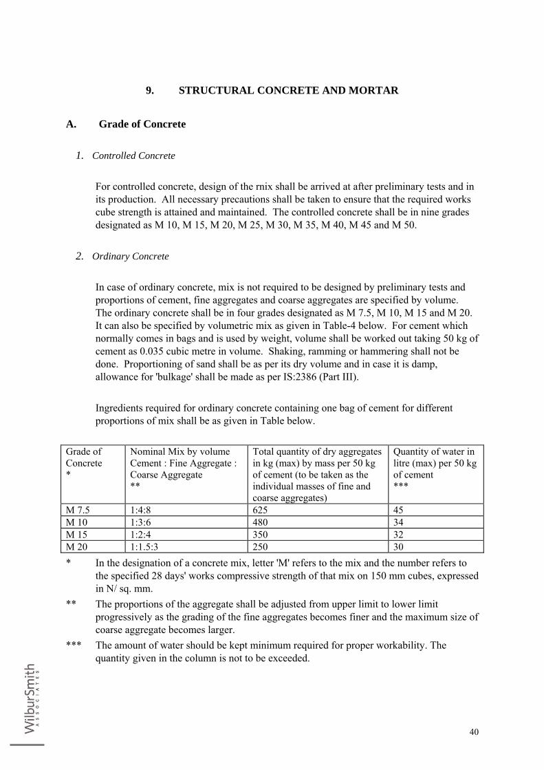
40
9. STRUCTURAL CONCRETE AND MORTAR
A. Grade of Concrete
1. Controlled Concrete For controlled concrete, design of the rnix shall be arrived at after preliminary tests and in
its production. All necessary precautions shall be taken to ensure that the required works cube strength is attained and maintained. The controlled concrete shall be in nine grades designated as M 10, M 15, M 20, M 25, M 30, M 35, M 40, M 45 and M 50.
2. Ordinary Concrete
In case of ordinary concrete, mix is not required to be designed by preliminary tests and
proportions of cement, fine aggregates and coarse aggregates are specified by volume. The ordinary concrete shall be in four grades designated as M 7.5, M 10, M 15 and M 20. It can also be specified by volumetric mix as given in Table-4 below. For cement which normally comes in bags and is used by weight, volume shall be worked out taking 50 kg of cement as 0.035 cubic metre in volume. Shaking, ramming or hammering shall not be done. Proportioning of sand shall be as per its dry volume and in case it is damp, allowance for 'bulkage' shall be made as per IS:2386 (Part III).
Ingredients required for ordinary concrete containing one bag of cement for different
proportions of mix shall be as given in Table below. Grade of Concrete *
Nominal Mix by volume Cement : Fine Aggregate : Coarse Aggregate **
Total quantity of dry aggregates in kg (max) by mass per 50 kg of cement (to be taken as the individual masses of fine and coarse aggregates)
Quantity of water in litre (max) per 50 kg of cement ***
M 7.5 1:4:8 625 45 M 10 1:3:6 480 34 M 15 1:2:4 350 32 M 20 1:1.5:3 250 30 * In the designation of a concrete mix, letter 'M' refers to the mix and the number refers to
the specified 28 days' works compressive strength of that mix on 150 mm cubes, expressed in N/ sq. mm.
** The proportions of the aggregate shall be adjusted from upper limit to lower limit progressively as the grading of the fine aggregates becomes finer and the maximum size of coarse aggregate becomes larger.
*** The amount of water should be kept minimum required for proper workability. The quantity given in the column is not to be exceeded.
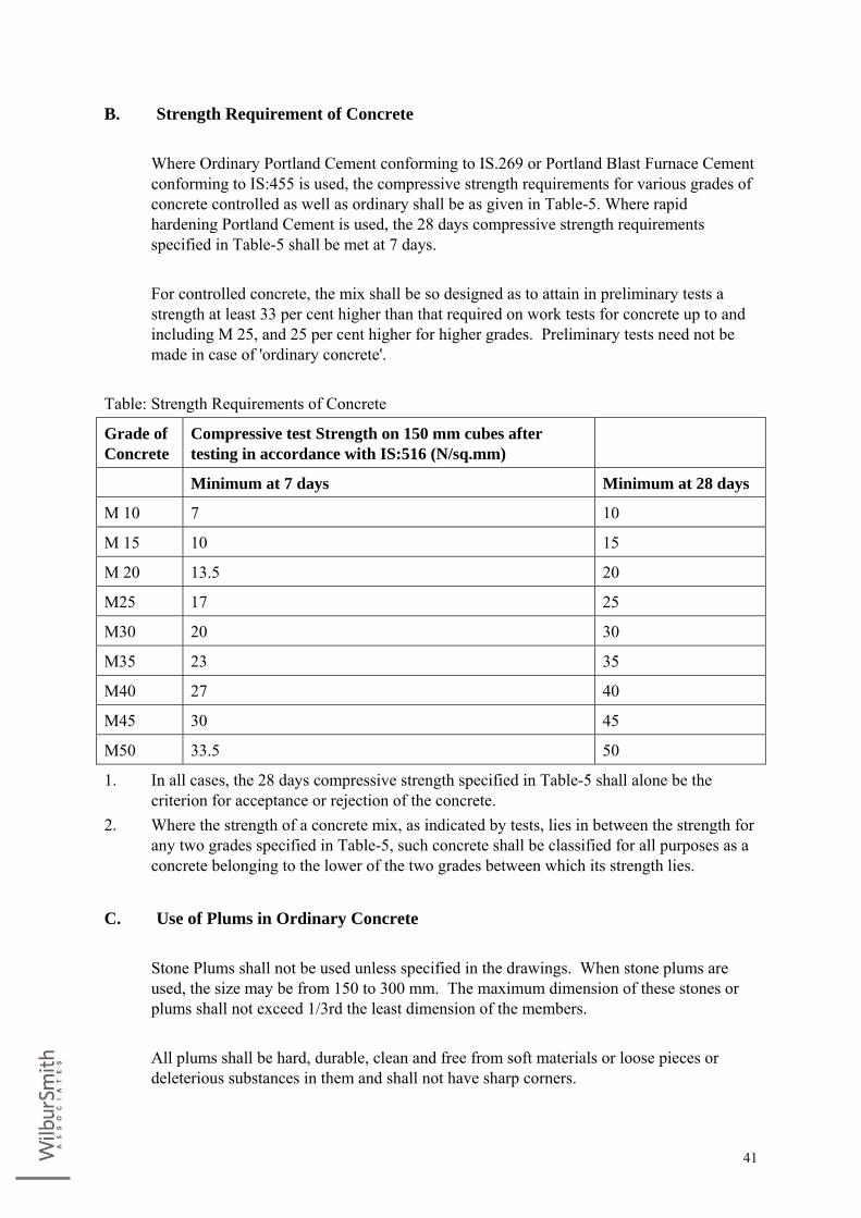
41
B. Strength Requirement of Concrete Where Ordinary Portland Cement conforming to IS.269 or Portland Blast Furnace Cement
conforming to IS:455 is used, the compressive strength requirements for various grades of concrete controlled as well as ordinary shall be as given in Table-5. Where rapid hardening Portland Cement is used, the 28 days compressive strength requirements specified in Table-5 shall be met at 7 days.
For controlled concrete, the mix shall be so designed as to attain in preliminary tests a
strength at least 33 per cent higher than that required on work tests for concrete up to and including M 25, and 25 per cent higher for higher grades. Preliminary tests need not be made in case of 'ordinary concrete'.
Table: Strength Requirements of Concrete
Grade of Concrete
Compressive test Strength on 150 mm cubes after testing in accordance with IS:516 (N/sq.mm)
Minimum at 7 days Minimum at 28 days
M 10 7 10
M 15 10 15
M 20 13.5 20
M25 17 25
M30 20 30
M35 23 35
M40 27 40
M45 30 45
M50 33.5 50
1. In all cases, the 28 days compressive strength specified in Table-5 shall alone be the criterion for acceptance or rejection of the concrete.
2. Where the strength of a concrete mix, as indicated by tests, lies in between the strength for any two grades specified in Table-5, such concrete shall be classified for all purposes as a concrete belonging to the lower of the two grades between which its strength lies.
C. Use of Plums in Ordinary Concrete Stone Plums shall not be used unless specified in the drawings. When stone plums are
used, the size may be from 150 to 300 mm. The maximum dimension of these stones or plums shall not exceed 1/3rd the least dimension of the members.
All plums shall be hard, durable, clean and free from soft materials or loose pieces or
deleterious substances in them and shall not have sharp corners.

42
During concreting the first layer of concrete of the specified mix shall be laid to a thickness of at least two and a half times the thickness of the maximum size of plums to be used. The plums shall then be laid while the top portion of this concrete is still green but sufficiently stiff to prevent complete submergence of the plums under their own weight. These plums shall be about half embedded in the concrete and the remaining part exposed so as to form a key with the next layer of concrete. No plums shall be used for concrete-laid under water.
While placing the plums, care shall be taken to see that the clear distance between any two
plums is not less than either the width or thickness of either of the plums. The distance from plums to the outer surface or from any steel reinforcement shall be equal to greatest width of the plum.
If plums of stratified stone are used, they shall be laid on their natural bed. Stones with
concave faces shall be laid with the concave portion upwards. The thickness of the next and successive layers of concrete shall be at least twice that of the largest plums. The total volume of plums shall not exceed 15% of the volume of the finished concrete.
10. ANCILLARY STRUCTURES
A. Valve Chambers, Thrust Blocks/Anchor blocks The Contractor shall build Valve Chambers & Thrust Blocks/Anchor blocks and such
other miscellaneous structures that may be required at the locations shown by the Engineer and as shown in the drawings or as may be otherwise specified or directed. The various structures shall be built as the pipe laying progresses and the Engineer at his discretion, may stop work entirely on the laying of pipe or construction of other structures, until the construction of the structures already approved by the Engineer are completed by the Contractor. Brick masonry/RCC Valve chamber of required size shall be constructed at the locations mentioned earlier for various valves. Floor will have minimum 300 mm gap under the valves. The valve chamber floor shall have a mild slope towards an opening provided on one of the side walls, to drain off any collected or scoured water. Drain channels shall be provided to the nearest storm water drain, from the valve chamber. The valves shall be supported on suitable foundations. The valve chamber need not be provided with any water proof painting.
1. Pipe Supports
Pipe supports shall be constructed as per Clause 17.6 of Chapter 10, Standard
Specifications for Procurement of Project Works, wherever needed, as per the directions of the Engineer. Pipe supports shall be of saddle type. Pipe supports shall also be provided for the stretches of the pipe, where the pipe is to be gradually brought above the ground for crossing any obstructions as shown in the drawings. The distance between pipe supports shall not exceed 5.0 m centre-to-centre.
Pipe supports shall be as per the approved designs and to be taken to a depth of at least 1.
43
30 mtrs. below ground level as shown in the drawing and shall have sufficient height above ground to be able to support the pipe. 20 mm dia tor steel clamp shall be provided all round the pipe and fixed to the pipe supports using appropriate means as shown in the drawings or as directed by the Engineer.
There shall be no joints at the location of the pipe supports. The joints shall be located on
any one side of the support, at a minimum distance of 200 mm from the face of the support.
The successful bidder should execute the pipe supports as per the approved designs
obtained from the Employer.
2. Thrust Blocks Thrust blocks shall be provided for both horizontal and vertical bends greater than 5o, to
effectively transfer the hydrostatic thrust developed during the operation of the rising main, to the ground. They shall be constructed at the locations shown in the alignment drawings, and are of the respective dimensions shown therein, depending on the angle of bends, and the pressures developed in the main. They shall be constructed as per Clause 17.5 of Chapter 10, Standard Specifications for Procurement of Project Works. The surrounding virgin land of the thrust blocks shall not be disturbed, to effectively transfer the thrust developed in the main.
3. Valve chambers
Stone masonry/RCC valve chambers shall be provided for all valves. The specifications of
the valve chamber shall generally confirm to Clause 17.4 of Chapter 10, Standard Specifications for Procurement of Project Works. These valve chambers are of different sizes suitable for air valves & scour valves with RCC pre-cast slabs covering . They shall be constructed as per the details shown in the drawings. The stone masonry valve chamber with RCC pre-cast cover, shall be constructed as shown in the Drawings for all Valves. It shall have a opening in the side wall for access into it. Outside the valve chambers, for scouring of water, draft channels shall be provided.
4. Structures for Crossing Canal/ Nallahs and Other Miscellaneous Structures
Structures for crossing the pipeline over canals/Nallahs and other miscellaneous structures
not listed in these specifications but may be required to be built shall be as per construction drawings and as described in Bill of quantities. The materials of construction and workmanship for those structures shall conform to the relevant Standard Specifications.
11. PIPE LINE CONNECTIONS
44
The Contractor is responsible for giving suitable connections at the inlet and outlet ends of the WTP, RWPS, CWPS, pipelines, OHT. Etc.,
A. Crossings of Roads and Culverts Under major roads and rail line, as directed by Engineer, the rising main shall be laid
inside a steel casing pipe. Steel pipe shall be used for such crossings and for culvert crossings as casing pipe and will be pushed through trenchless technology. The details of such crossings shall be furnished in construction drawings.
12. PROVIDING & INSTALLING BULK & DOMESTIC WATER METERS WITH STRAINERS
A. Technical Specifications for 15/20/25/32mm Domestic Water Meters Technical Specification for Water Meters conforming to Class – B of ISO:4064 / IS 779 –
1994 and its latest amendments. The meter will be used for the measurement of cold, chlorinated potable water. (i) Domestic Water Meters (Multi Jet) (ii) Domestic Water Meters (Multi Jet) with Automatic Meter Reading (iii) Woltmann Helical Flow meter with Automatic Meter Reading (iv) Bulk Water Meters (Full Bore Electromagnetic Flow meters)
B. Applicable Standards The meter shall conform to both IS 779 and ISO (4064) standards with latest amendments.
Valid EEC certification or equivalent certification is necessarily for the manufacturing unit from where the meters would be supplied.
This certificate shall be valid at least up to end of 2010. For EEC meters, the bidders
should categorically mention the following:
• Name, address and contact details with phone, fax details of the EEC / equivalent approval issuing authority.
• Validity of the approval.
Alternative to EEC certificate / Life cycle & accuracy test certificate conducted after May 2005 by FCRI / NABL / Other accredited laboratories should be enclosed with the bid as well as any other technical document which may help in assessing the technical merits and suitability of the meters for the prevailing operating conditions.
The meters shall be:
• Super dry dial
45
• Hermitically sealed • Minimum Class B • Fitted with inbuilt pulse output suitable for AMR, strainer, non return valve and brass
connectors • Nominal size of water meters shall be 15mm, 20mm, 25mm & 32mm
Materials which come in contact with the water supply shall withstand 2 ppm (parts per
million) of chlorine residual in the water supply and shall be resistant to corrosion. The water meter and accessories shall be manufactured from materials of adequate
strength and durability. The materials, which come in contact with the potable water, shall not create a toxic hazard, shall not support microbial growth, and shall not give rise to unpleasant taste or discoloration in the water supply.
Construction: Meter shall be as per clause 9 of IS 779 – 1994 or relevant clauses of ISO
4064-1. The Material of Construction shall be as per IS standards. Each meter will be supplied with two cylindrical nipples or tail pieces with connecting nuts. Threads on the connection shall conform to latest version of IS 2643 (part 1 to3) or ISO 228-1. All meters shall be supplied with an easily removable tubular inlet strainer. The Seal & Sealing wires shall be rust proff material like engineering plastic.
C. Nominal Capacity The nominal capacity of the meter shall be Qn 1.5m3/hour
D. Accuracy Class The accuracy of the meter shall be in accordance with ISO 4064 class B and IS 779 – 1194
and its latest amendments.
E. Accuracy at 0,5 Qmin The accuracy range of the meter at a flow rate of 0,5 Qmin shall be between +/-5%.
F. Pressure and Temperature The working pressure shall not be less than 16 bar and shall conform to the testing in
accordance with ISO 4064. The meter shall be capable to operate in an ambient temperature of up to 50ºC
G. Pressure Loss The pressure loss through the water meter shall not be greater than 0.25 bar at Qn and 1.0
46
bar at Qmax
H. Meter Markings The water meter shall be marked with the following identifications:
(i) Direction of water flow with an arrow indicating the direction. (ii) Trade mark and/or name of the Manufacture. (iii) The metrological class and Qn rate in m3 per hour. (iv) The Manufacture’s Serial number of the meter permanently affixed to the meter’s
upper or lower case. (v) Stamped with the initial “PHE” (vi) Working pressure. (vii) Approval marking and No. of approval certificate. (viii) Year of manufacturing printed on the counter or engraved on the head ring. (ix) EEC mark on the meter dial.
I. Accessories The meter shall include the following accessories:
• Two threaded tailpieces which shall conform to BS 21 for threaded end Meters. • An internal non-return-valve.
J. Conformance to Meter Testing The type or make of the meter which shall be supplied be tested as per the provision of IS
779 read with IS 6784 or ISO 4064-1 for the following: • Acceptance tests • Type tests
In addition of the above, all the meters supplied shall be tested for the Production Routine
tests as per provisions of clause 12.3 of IS 779. The manufacturers Production Routine test certificates along with every meter supplied shall be submitted to the Engineer.
The meter shall be tested for registration accuracy as per IS. The test bench from the respective manufacturer for the water meter shall be established
one complete setup in Panipat city to take care of repairs, test and other complaints from the customer.
47
K. Meter Size and overall dimensions Nominal diameter of the meters shall be 15mm, 20mm, 25mm and 32mm. Meter threads,
nominal flow rate, minimum length of threads on either side, overall dimensions shall be as per table 2 of IS 779 or table 1 of ISO 4064-1.
L. Seal The meter shall be sealed by the manufacture before delivery and shall be provided with a
hole for sealing the meter with the service valve on the inlet side of the meter
M. Specifications for Installation of Meters
(i) The bidder shall install the water meters as per IS/ISO installation standards and manufacturer’s recommendations.
(ii) The bidder shall submit the drawing for installation of meters of various sizes and get it approved from Engineer before installation.
13. SPECIFICATION FOR WOLTMANN TYPE BULK METERS CLASS B
A. Scope The Bulk Meter shall be as per ISO 4064/ 1 & EEC approval (Certification). The meter
will be Class B Woltmann type (Helical blades which rotates about the axis of flow in the meter ) magnetically coupled suitable for cold potable water meter for water supplies having sizes from 50 mm to 500 mm. Maximum admissible working pressure (MAP) upto 10 bar. The meter will have hermetically sealed register press, which will be waterproof, and the unit will be provided with maximum corrosion protection.
B. Materials Water meters shall be made of materials of adequate strength and stability for the purpose
for which the water meter is to be used. It must be manufactured throughout of materials, which are resistant to internal and normal external corrosion and if necessary be protected by some suitable surface treatment. All materials of the water meter, which are in contact with water, shall be resistant to corrosion and shall be nontoxic and non-staining. Use of dissimilar metals in contact under water shall be avoided as far as possible in order to minimize electrolytic corrosion. Water temperature variation within the temperature range specified must not adversely affect the materials used in the construction of the water meter.
48
C. General
(i) The register shall be hermetically sealed (IP-68) and Rota table through 360°. The water meters shall be capable of being fitted in any position i.e. horizontal, vertical or inclined going upward only.
(ii) The meter size, designation and overall dimensions shall conform to ISO 4064 part I class B.
(iii) The water meter shall have flanged connections. The flanged connections shall comply with IS 1538 part iv & vi for a nominal pressure corresponding to that of the water meter.
(iv) The manufacturer shall provide a reasonable clearance behind the rear face of the flange to allow access for installation and removal.
(v) Type of indicating Device: The indication of meter shall be a combination of analog and digital as per ISO 4064 Part -1.
(vi) Sealing & Marking: Sealing and marking of the water meters shall conform to 4.10 & 4.11 of ISO 4064 Part I.
(vii) Maximum Permissible errors: The maximum permissible error in the lower zone from qmin inclusive upto but
excluding q t is + 5 %. The maximum permissible error in the upper zone from qt inclusive upto and
including qs is + 2 %. The meters shall be able to retain their accuracy when installed in horizontal,
vertical or inclined planes going upward only. (viii) The meter performance specification shall be as per ISO 4064/1, Class B. Copies of
the relevant Production Test Certificates are to be provided by the meter manufacturer.
(ix) The meter shall be able to withstand a maximum working temperature of 45° C. (x) Meters shall be designed for easy disassembly and re-assembly without the use of
special tools or equipment and shall be easy to maintain and repair. Meters shall be designed to resist tampering.
(xi) The casing shall be powder coated CI. Workman ship shall be good. All burrs and sharp edges shall be removed and the inside surface shall have smooth finish.
(xii) Hydrostatic Test at 16 bars in accordance with ISO 4064 -3: 1999 shall be witnessed by the purchaser.
(xiii) Catalog / Literature shall be submitted with the offer. GA and cross sectional drawings with part numbers, material of construction and major dimensions, QAP etc. shall be submitted to purchaser for approval after placement of order.
(xiv) The supplier shall submit following documents during inspection. • Chemical Test and mechanical test certificate. • Warranty Certificate. • Hydro Test Certificate. • EEC Certificate. •
49
D. Markings Each meter shall be marked with the following information: (i) Manufacturers name or Trade Mark. (ii) Nominal size and class of meter. (iii) Direction of flow of water on both sides of meter. (iv) Year of Manufacturing & Serial No. (v) UWSEIMP (vi) EEC Certificate.
E. Strainer Strainers shall be made of material, which is not susceptible to electrolytic corrosion. They
shall be of corrosion resistant materials. They shall be rigid, easy to remove and clean and shall be fitted as separate unit before water meter on the inlet side of the meter. The strainer shall have total area of holes not less than four times the area of the nominal inlet bore of the pipe to which the meter is connected. It shall be at installed at such a place that it does not affect the accurate functioning of the meter.
A strainer shall be provided upstream of the water meter to avoid any foreign material
entering into the meter. The strainer shall be with flanged connection as per IS 1538. Body of the strainer shall be of CI conforming to FG 200 of IS 210 – 1978 and filter material shall be of stainless steel AISI304, 40 mesh. Gasket shall be rubber as per IS 638. Bolts and Nuts and washers shall be as per IS 1367 clause 4.6/4
Tests to be witnessed by purchaser are Hydro Test of body at 15kg per cm2 and pressure
drop across strainer less than 0.5 kg per cm2. Workman ship shall be good. All burrs and sharp edges shall be removed and the inside
surface shall have smooth finish. Painting shall be one coat of primer followed by two coats of enamel paint.
Catalog / Literature shall be submitted with the offer. Cross sectional drawings with part
numbers, material of construction and major dimensions shall be submitted to purchaser for approval after placement of order.
The supplier shall submit following documents during inspection.
(i) Chemical Test and mechanical test certificate. (ii) Warranty Certificate. (iii) Hydro Test Certificate. (iv) QAP (v) Performance Test Certificate
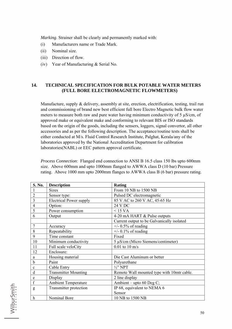
50
Marking. Strainer shall be clearly and permanently marked with:
(i) Manufacturers name or Trade Mark. (ii) Nominal size. (iii) Direction of flow. (iv) Year of Manufacturing & Serial No.
14. TECHNICAL SPECIFICATION FOR BULK POTABLE WATER METERS (FULL BORE ELECTROMAGNETIC FLOWMETERS)
Manufacture, supply & delivery, assembly at site, erection, electrification, testing, trail run
and commissioning of brand new best efficient full bore Electro Magnetic bulk flow water meters to measure both raw and pure water having minimum conductivity of 5 µS/cm, of approved make or equivalent make and conforming to relevant BIS or ISO standards based on the origin of the goods, including the sensers, loggers, signal convertor, all other accessories and as per the following description. The acceptance/routine tests shall be either conducted at M/s. Fluid Control Research Institute, Palghat, Kerala/any of the laboratories approved by the National Accreditation Department for calibration laboratories(NABL) or EEC pattern approval certificate.
Process Connection: Flanged end connection to ANSI B 16.5 class 150 lbs upto 600mm
size. Above 600mm and upto 1000mm flanged to AWWA class D (10 bar) Pressure rating. Above 1000 mm upto 2000mm flanges to AWWA class B (6 bar) pressure rating.
S. No. Description Rating 1 Sizes From 10 NB to 1500 NB 2 Sensor type: Pulsed DC electromagnetic 3 Electrical Power supply 85 V AC to 260 V AC, 45-65 Hz 4 Option: 24 V DC 5 Power consumption < 15 VA 6 Output 4-20 mA HART & Pulse outputs Current output to be Galvanically isolated 7 Accuracy +/- 0.5% of reading 8 Repeatability +/- 0.1% of reading 9 Time constant Fixed 10 Minimum conductivity 5 µS/cm (Micro Siemens/centimeter) 11 Full scale veloCity 0.01 to 10 m/s 12 Enclosure: a Housing material Die Cast Aluminum or better b Paint Polyurethane c Cable Entry ½” NPT d Transmitter Mounting Remote Wall mounted type with 10mtr cable. e Display 2 line display f Ambient Temperature Ambient – upto 60 Deg C; g Transmitter protection IP 68, equivalent to NEMA 6
Sensor h Nominal Bore 10 NB to 1500 NB
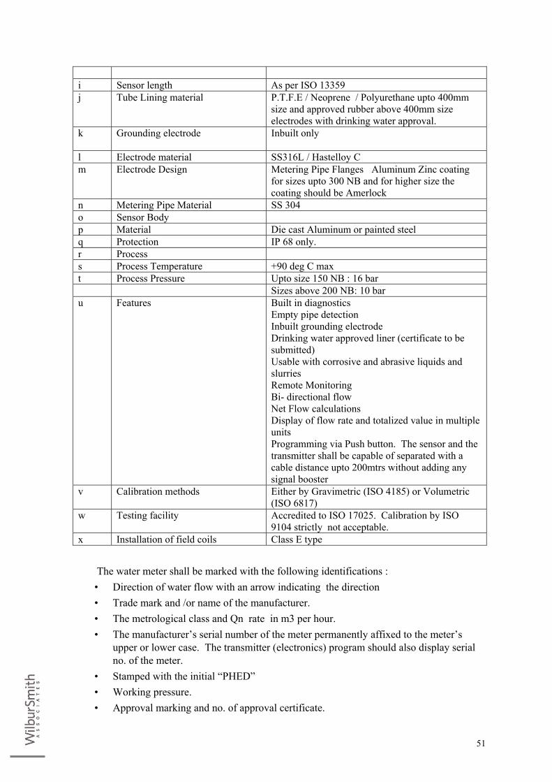
51
The water meter shall be marked with the following identifications :
• Direction of water flow with an arrow indicating the direction • Trade mark and /or name of the manufacturer. • The metrological class and Qn rate in m3 per hour. • The manufacturer’s serial number of the meter permanently affixed to the meter’s
upper or lower case. The transmitter (electronics) program should also display serial no. of the meter.
• Stamped with the initial “PHED” • Working pressure. • Approval marking and no. of approval certificate.
i Sensor length As per ISO 13359 j Tube Lining material P.T.F.E / Neoprene / Polyurethane upto 400mm
size and approved rubber above 400mm size electrodes with drinking water approval.
k Grounding electrode Inbuilt only
l Electrode material SS316L / Hastelloy C m Electrode Design Metering Pipe Flanges Aluminum Zinc coating
for sizes upto 300 NB and for higher size the coating should be Amerlock
n Metering Pipe Material SS 304 o Sensor Body p Material Die cast Aluminum or painted steel q Protection IP 68 only. r Process s Process Temperature +90 deg C max t Process Pressure Upto size 150 NB : 16 bar Sizes above 200 NB: 10 bar u Features Built in diagnostics
Empty pipe detection Inbuilt grounding electrode Drinking water approved liner (certificate to be submitted) Usable with corrosive and abrasive liquids and slurries Remote Monitoring Bi- directional flow Net Flow calculations Display of flow rate and totalized value in multiple units Programming via Push button. The sensor and the transmitter shall be capable of separated with a cable distance upto 200mtrs without adding any signal booster
v Calibration methods Either by Gravimetric (ISO 4185) or Volumetric (ISO 6817)
w Testing facility Accredited to ISO 17025. Calibration by ISO 9104 strictly not acceptable.
x Installation of field coils Class E type

52
• Year of manufacturing printed on the counter or engraved the head ring. • Minimum sustainable pressure shall be PN 16 bar
Flow rate; minimum, maximum and transition flow shall be as per relevant standards. The successful bidder shall arrange to give training to minimum of 2 Engineer-in-charge
regarding erection, installation & functionality of bulk flow meter of selected manufacturer at the original manufacturing place for minimum of 5 days.
Note: 1. If the flow meter size works out to be smaller than the pipeline size, bidder shall offer
suitable reducers and expanders. The reducers / expanders shall be of MS, smaller dia end flanged to suit the flow meter flanges and the larger dia end finished for welding to the pipe. The conical angle of reduction should not exceed 10 deg. The bidder should guarantee that installation of such reducers and expanders immediately before and after the flowmeter will not affect the accuracy stated for the flowmeter.
2. The accuracy of calibration of flowmeter at factory shall be better by a factor of 2 than the guaranteed accuracy. This higher accuracy should be reflected in the calibration certificate of flowmeter (+/- 0.25% for 0.5% accuracy and +/- 0.4% for 0.8% accuracy).
3. The bidder shall include 25mtr cable length in the basic offer.
15. SERVICE CONNECTIONS One Service Connection means one tapping from a distribution main/ sub-main including
one tapping saddles, elbows, service pipe from tapping point to the chamber near property boundary or inside the property boundary as per the direction with U-ball valve.
The house connection using Medium Density Polyethylene pipes (MDPE) shall consist of
the following;
A. Option 1 Electro Fusion Tapping Ferrule of PN 12.5 PE 100 compatible to the HDPE Mains of
various diameters. The outlets should be reinforced with female threaded metal inserts of SS 304, metal inserted male thread elbow, MDPE PE 100 Blue pipes, 90 deg double compression elbows, UPVC ball valves of required sizes and water meter. The outlet size shall be either 15mm, 20 mm depending upon the type of Service Connection.
Electro fusion Tapping Ferrule shall be provided with a SS-304 Brass cutter with cutting
edges for making hole / tapping on the Mains as shown in drawing and Fusion joint in such a manner that the 20-63mm dia outlet depending on requirement of the house service connections rotateable 3600 to the axis of pipeline including maintaining the same for the period under O&M.
53
B. Option 2 Providing required sizes of HSC brass ferrule with union confirming to relevant IS make
hole by drilling on top of DI distribution mains, fixing the ferrule for diameter 200 to 400mm and making the connection water tight etc., as shown in the drawing and as directed by the Engineer including cost of required specials, drilling charges, hydraulic testing, maintaining the same for the period under O&M.
From tapping on DI mains, metal inserted male thread elbow, MDPE PE 100 Blue pipes, 90 deg double compression elbows, UPVC ball valves of required sizes and water meter.
C. Items common for both options: From the outlet of Male Threaded compression Elbow, 15/ 20 mm MDPE BLUE Service
Pipe shall be extended upto the RCC/BBM chamber at property boundary as shown in the drawing. At the end of the Service pipeline, 90 Deg Double Compression Elbow shall be fixed and MDPE Service pipe shall be connected. From the Service Pipe, a U PVC Ball valve of necessary size with Compression joint at one side and Female joint at one side. The Ball valve shall be as per ISO 4422 Part 4 and rated PN 12.5.
The entire assembly shall be as per the enclosed drawing. The connecting pipe shall be made out of MDPE conforming to ISO 4984 & ISO 4427-
1996. This International standard specified the required properties of pipes made from polyethylene (PE) to be used for buried water mains and services and for water supply above ground both inside and outside buildings. In addition, it specifies some general properties of the material from which these pipes are made, including a classification scheme. Other relevant IS and International Standards applicable for the MDPE pipe shall be followed as approved by the Engineer.
The MDPE Pipes for drinking water applications should have undergone type test by
WRc-NSF, U.K. according to BS 6920 and a certificate from either WRc-NSF or WRAS (Water Regulations Advisory Scheme) should be available evidencing this fact.
16. TECHNICAL SPECIFICATIONS FOR ELECTRO FUSION TAPPING All the electro fusion fittings included in this document will be designed for use in water
distribution system and be manufactured/supplied by manufacturers having ISO 9001-2000 certification for their quality systems. The products should comply with the following specific requirements.
(i) All the electro fusion fittings should (George Fisher/Wavin/Kimplast/ Equivalent)
have Melt Flow Rate (MFR) in the range between 0.4 to 1.4 gms /10 min and shall be compatible for fusing on PE 100 distribution line manufactured according to the relevant national or international standards. The polymer used should comply with the requirements of BS 3412 and/or BS EN 12201-1.
54
(ii) All the electro fusion fittings should be manufactured in Black PE100- material
which should be compatible with the distribution mains. (iii) The tapping saddles to have drilling cutter which enable s tapping even below the
maximum permissible operating pressure; the disc cut out of the pipe wall is permanently kept in the drilling cutter.
(iv) The products shall comply with the requirements of BS EN 12201-3: 2003, BS EN
1555-3 or ISO 8085-3. (v) All the fittings shall be of SDR 11 rating. (vi) The product group used for drinking water applications should have undergone type
test by WRc-NSF, U.K. according to BS 6920 and a certificate from either WRc-NSF or WRAS (Water Regulations Advisory Scheme) should be available evidencing this fact.
(vii) All the products shall be manufactured by injection moulding using virgin
compounded PE 100 (MDPE) polymer having a melt flow rate between 0.5 – 1.1 grams/10 minutes and shall be compatible for fusing on PE 100 distribution mains manufactured according to the relevant national or international standards. The polymer used should comply with the requirements of BS 3412 and/or BS EN 12201 -1.
(viii) The fittings intended for water distribution applications shall be coloured black for
the clear identification of the services. (ix) All the electro fusion products should be individually packed so that they can be
used instantaneously at site without additional cleaning process. The protective packing should be transparent to allow easy identification of the fittings without opening the bags.
(x) The electro fusion products should be with only a single heating coil to fully electro
fuse the fitting to the adjoining pipe or pipe component as applicable. The heating coils shall be terminated at terminal pins of 4.0 or 4.7 millimeter diameter, protected with polyethylene shroud. Each terminal shroud should be additionally protected with polyethylene shroud caps.
(xi) No heating element shall be exposed and all coils are to be integral part of the body
of the fitting. The insertion of the heating element in the fitting should be part of the injection moulding process and coils inserted after the injection moulding process or attached to the body of the fitting as a separate embedded pad etc. are strictly not acceptable.
55
(xii) The pipe fixation shall be achieved by external clamping /suitable devices as directed by the Engineer in charge.
(xiii) The brand name, size, raw material grade, SDR rating and batch identification are to
be embedded as part of the injection moulding process. Each fitting should also be supplied with a barcode sticker for fusion parameters attached to the body for setting the fusion parameters on an fusion control box. The barcode sticker should also include the fusion and cooling time applicable for the fitting for the manual setting of a manual fusion control box.
(xiv) The fittings should be V-regulated type designed to fuse at a fusion voltage of 40
volts AC. (xv) The heating elements should be designed for fusion at any ambient temperatures
between -5 to +40 degree centigrade at a constant fusion time i.e. without any compensation of fusion time for different ambient temperatures.
(xvi) A limited path style fusion indicator acting for each fusion zone as visual
recognition of completed fusion cycle should be incorporated into the body of each fitting near the terminals. The fusion indicators should not allow the escape of the molten polymer through them during or after the fusion process.
(xvii) All the sockets in the electro fusion fittings should include a method of tapping
controlling the pipe penetration (pipe positioner/stopper). (xviii) The EF tapping ferrules should be the top loading type which are to be clamped on
the mains for fusion using the custom made top loading clamps exerting 1500N (150 kilograms approximately) top load.
(xiv) The tapping ferrules should be supplied with suitable adaptors for proper positioning of the top-loading clamp into the saddle.
(xx) The Torque required to operate the cutter after fusion of the PE mains should not
exceed 45 N-m. (xxi) The cutter should be designed in such a way that the cut coupon is not allowed to
fall into the pipeline and is retained inside the body of the cutter providing a positive sealing of the hole in the cutter head for pressure testing.
(xxii) The tapping ferrules will have female threaded outlet to connect necessary
compression fittings for further connecting MDPE Pipe in House connection. (xxiii) The threaded outlet should be from sizes ½” to 1” BSP to suit the required House
Service Connections.
56
(xxiv) The outlets should be reinforced with female threaded metal inserts of SS 304.
17. INSTALLATION AND FUSION JOINTING The fusion jointing process shall be carried out as per the procedure outlined in the
DVS220 standard, if not available equivalent standards acceptable to employer. A protocol for each fusion joint to be printed to ensure the joint process carried out is error
free. The electro fusion machine shall have the facility to record & make print for each joint.
The precautions & measures as mentioned by electro fusion fittings/machine manufacturer
be taken up rigorously while making the joints in the field. The related pipe jointing accessories such as proper pipe cutter, Universal scrapped
clamping kits, Pipe cleaners, Top load tools(for tapping saddle installation), Pipe peelers supplied by the same electro fusion fitting/machine supplier shall be used to ensure perfect jointing.
The usage of tapping tools such as taping keys, tension clamps supplied by the same
electro fusion fitting /machine supplier must be used to ensure perfect tapping of main lines.
The piping system will be tested as per the guidelines given by ISO standard. The
guideline shall be furnished by the supplier of electro fusion fittings, tools and machines.
18. ELECTRO FUSION WELDING MACHINE Supplying delivery and testing at site (Fusion Provida/George Fisher/Equivalent approved
makes of Electro fusion welding machine as under: The electro fusion control unit shall be designed for use with any electro fusion fittings
required upto 48V. The unit shall operate in three modes, Automatic, Manual and Barcode. The unit shall be complete with all accessories and shall have the following features as minimum.
Full output voltage and output current monitoring throughout the jointing cycle. Automated output voltage (True RMS) level control between 10 and 48 VAC Graphical display of output current and voltage levels. Data logging facility for storing minimum 600 joint records and facility for data transfer
57
and print out. Required software shall be provided. Shall have Soft start feature to present shock loading on generators. Temperature compensation facility. Protection against fitting overheat. The unit shall give user friendly step by step operator instructions and printing facility (in
English & Hindi languages). Shall have back-lit graphical display. Shall have a single combined lead for all modes of operation. RS 232 serial interface cable shall be provided along with the unit. The machine shall be provided with barcode reader and adaptors if any required. These unites are provided with 7 segment display unit to select the output voltage,
Temperature, Fusion Time and Error message in case of malfunctions occurring before or during the Fusion.
The output voltage level control shall be between 10 and 44 VAC. Specification Operating Temperature Range (Min). -10 to +50 Deg C Operating Voltage Range (min) 190 V to 270 V, 45 to 50 Hz Output Voltage 8 to 44 VAC 10 – 44 VAC (Barcode Mode) Enclosure Protection IP 54 Input Cable length Minimum 12 meters Output Cable length Minimum 4 meters
19. COMPRESSION FITTINGS Compression fittings used for House service connection comply as per ISO 14236
A. Material of Construction Compression fittings material shall confirm to ISO14236.Clause -5.
(i) Body-Polypropylene
58
(ii) Nut / Cap –Polypropylene. (iii) Clip Ring-POM (Acetylic resin ) (iv) Packing bush- Polypropylene (v) “O” ring - NBR (vi) Threaded metal inserts –SS 304 with BSP Threads
B. Pressure testing The pressure rating of compression fittings as per clause 8 of ISO 14236 which shall be
PN16
C. Dimensions The Dimension of compression fittings shall be as per clause 7.1 of ISO 14236
D. Performance requirements The compression fittings shall be tested as per ISO 14236. Following Test methods shall
be performed.
Clause 8.2.1 -Leak tightness under internal pressure. Clause 8.2.2 -Resistance to Pull out. Clause 8.2.3 -Leak tightness under Internal Vaccum. Clause 8.2.4 -Long term Pressure Test for Leak tightness for assembled joint Clause 8.3.2.1 -MRS Value as per ISO 9080 Clause 8.3.3.1 -Resistance to Internal pressure.
E. Effects on Quality of Water The Compression fittings for intended for conveyance of Potable water for Human
consumption to be tested to comply with BS 6920 specifications in any of the laboratories like DVGM / KIWA / SPGN / WRc –NSF and certificate of compliance to be produced for the following parameters :
(i) Odour & Flavour of Water. (ii) Appearance of Water. (iii) Growth of Micro Organism (iv) Extraction of substances that may be of concern to Public Health (Cyto Toxicity) (v) Extraction of Metals.
59
For clear identification of the water services, the nuts of the fittings should be coloured
blue while the body to be black. All fittings with threaded ends should be with BSP threads.
20. U PVC BALL VALVES (STOP COCKS)
A. General Ball Valves used for HOUSE Service Connections comply to ISO 4422, Part 4. Material of Construction.Ball Valve material shall confirm to as per clause 4 of ISO 4422.
(i) Body and Handle - UPVC (ii) Seals - PTFE (iii) O-rings – NBR/EPDM (iv) Material of Construction for compression end will as per specifications for
compression fittings.
B. Pressure Rating The Pressure of the Ball Valve shall be as per ISO 4422 shall be PN 16.
C. Dimensions The Dimensions of the Ball Valve shall be as per Table 3 of ISO 4422.
D. Performance Requirements: The Ball valves shall be tested as per ISO 4422.Folowing test methods will be performed.
Clause 7.1 - Resistance of Valve Bodies to internal pressure Clause 7.2 - Crushing Test Clause 7.3 - Endurance Test Clause 7.4.2 - Seat and Packing Test Clause 7.4.1 - Operating torque Test
The Ball Valves intended for conveyance of Potable water for Human consumption to be tested to comply with BS 6920 specifications in any of the laboratories like DVGM / KIWA / SPGN / WRc –NSF and certificate of compliance to be produced for the following parameters :
60
(i) Odour & Flavour of Water. (ii) Appearance of Water. (iii) Growth of Micro Organism (iv) Extraction of substances that may be of concern to Public Health (Cyto ToxiCity) (v) Extraction of Metals.
21. MDPE PIPES These specifications are for MDPE Blue PE 100 Pipes for House Service Connections of
Dia 20 mm to 200 mm OD.
A. Raw Material Raw material used to Manufacture MDPE Blue Pipes shall be Virgin Natural Resin PE
100 containing those anti – oxidants, UV Stabilisers & Pigments necessary for Manufacturing of pipes. The Density of Pipes shall be in the Range 0.926 to 0.940 g/cm3 confirming to ISO 4984 & ISO 4427 Standard. The PE 80 Resin shall have MRS of 8 Mpa.
B. Effects on Water Quality The MDPE PE 100 Blue Pipes shall confirm to clause 3.5 of ISO 4984 & ISO 4427for
conveyance of Water for Human Consumption. Also the pipes intended for conveyance of Potable water for Human consumption to be tested to comply with BS 6920 specifications in any of the laboratories like DVGM/KIWA/SPGN/WRc-NSF and certificate of compliance to be produced for the following parameters
(i) Odour & Flavour of Water (ii) Appearance of Water (iii) Growth of Micro Organism (iv) Extraction of substances that may be of concern to Public Health (Cyto Toxicity) (v) Extraction of Metals
C. Pressure Rating The Pressure rating of MDPE Blue PE 100 Pipes shall be confirming to ISO 4984 &
Clause 4.1 of ISO 4427 : 1996.
D. Colour of Pipes The Colour of MDPE PE 100 Pipes shall be BLUE confirming to ISO 4984 & Clause 3.2
61
of ISO 4427: 1996.
E. Dimensions The pipe dimensions shall be as per latest revisions of ISO 4984 & Clause 4.1 of ISO 4427
: 1996 and pipes upto diameters 200 mm shall be supplied in Coils of 300 mtrs. The internal diameter, wall thickness, length and other dimensions of pipes shall be as per relevant tables of ISO 4427:1996. Each pipe shall be of uniform thickness throughout its length.
The wall thickness of the PE 100 Pipes shall be as per the table given below:
Nominal Dia of MDPE Pipe (mm) PR rating Wall thickness
Minimum Maximum
20 PN 16 2.3 2.8
25 PN 12.5 2.3 2.8
32 PN 12.5 3.0 3.5
The dimension tolerances shall be as per ISO 4427 clause 4.1.3
F. Performance requirements The Pipe supplied should have passed the acceptance test as per ISO 4427. The
manufacturer should provide the test certificates for the following tests.
i. Melt Flow Rate ii. Density, iii. Oxidation and Induction test, iv. Hydrostatic Test , v. Pigment dispersion Test, vi. Longitudinal Reversion Test.
These tests should be performed in the in-house laboratory of the pipe manufacturer. The
Employer will depute Third Party Inspection Agency to the pipe manufacturing facility of the manufacturer to inspect the pipes as per QAP approved by Engineer In charge.
22. SPECIFICATION FOR TUBSETTLER MEDIA
Product Tubesettler
General Specification Must be certified safe for drinking water application as per BIS guidelines
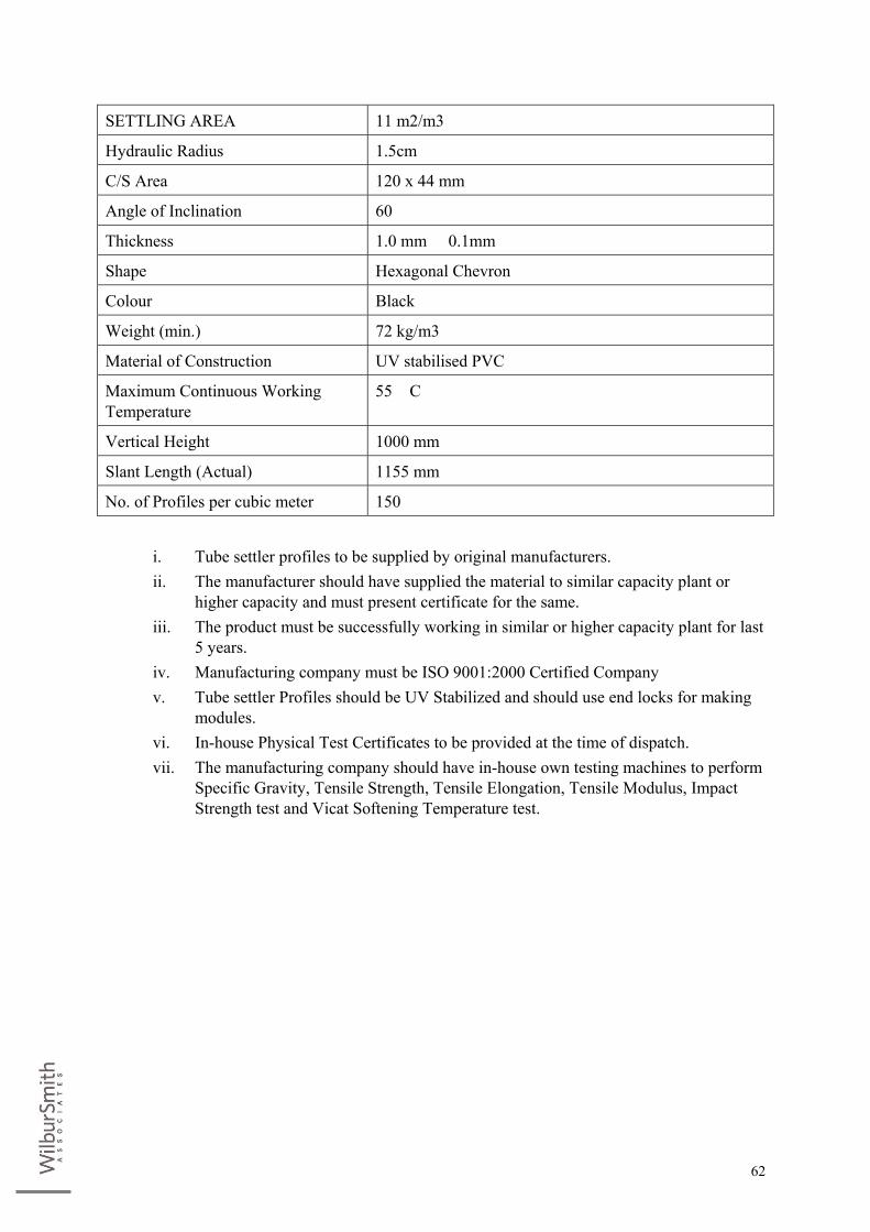
62
SETTLING AREA 11 m2/m3
Hydraulic Radius 1.5cm
C/S Area 120 x 44 mm
Angle of Inclination 60�
Thickness 1.0 mm � 0.1mm
Shape Hexagonal Chevron
Colour Black
Weight (min.) 72 kg/m3
Material of Construction UV stabilised PVC
Maximum Continuous Working Temperature
55� C
Vertical Height 1000 mm
Slant Length (Actual) 1155 mm
No. of Profiles per cubic meter 150
i. Tube settler profiles to be supplied by original manufacturers. ii. The manufacturer should have supplied the material to similar capacity plant or
higher capacity and must present certificate for the same. iii. The product must be successfully working in similar or higher capacity plant for last
5 years. iv. Manufacturing company must be ISO 9001:2000 Certified Company v. Tube settler Profiles should be UV Stabilized and should use end locks for making
modules. vi. In-house Physical Test Certificates to be provided at the time of dispatch. vii. The manufacturing company should have in-house own testing machines to perform
Specific Gravity, Tensile Strength, Tensile Elongation, Tensile Modulus, Impact Strength test and Vicat Softening Temperature test.

#8, Second Floor, 80 Feet Road,
RT Nagar Bangalore Karnataka - 560 032. India
w +91.80. 3918.7500 f +91.80. 2363.4097
www.WilburSmith.com


![[Concord 7055] [Panzers in the Gunsights]](https://img.dokumen.tips/doc/110x75/55cf9668550346d0338b4b44/concord-7055-panzers-in-the-gunsights-5681614dcd15f.jpg)


