Embed Size (px)
Citation preview
NAVAL POSTGRADUATE SCHOOL MONTEREY, CA
Rear Admiral R. C. Chaplin Richard Elster Superintendent Provost This report was prepared as an integral part of the Total Ship Systems Engineering
(TSSE) program educational process. Externally provided funds were not used. Reproduction
of all or part of this report is authorized, provided the source is cited.
This report was prepared by: CHARLES N. CALVANO ROBERT C. HARNEY Associate Professor Associate Professor, Mechanical Engineering Department Physics Department TSSE Program Chair TSSE Combat Systems Reviewed by: Released by: TERRY McNELLEY DAVID W. NETZER Chairman and Profesor Dean of Research Mechanical Engineering Department
1
REPORT DOCUMENTATION PAGE Form Approved
OMB No. 0704-0188 Public reporting burden for this collection of information is estimated to average 1 hour per response, including the time for reviewing instruction, searching existing data sources, gathering and maintaining the data needed, and completing and reviewing the collection of information. Send comments regarding this burden estimate or any other aspect of this collection of information, including suggestions for reducing this burden, to Washington headquarters Services, Directorate for Information Operations and Reports, 1215 Jefferson Davis Highway, Suite 1204, Arlington, VA 22202-4302, and to the Office of Management and Budget, Paperwork Reduction Project (0704-0188) Washington DC 20503.
1. AGENCY USE ONLY (Leave blank)
2. REPORT DATE May 1998
3. REPORT TYPE AND DATES COVERED Technical (7/97 – 12/97)
4. TITLE AND SUBTITLE A Short Take-off Vertical Landing (STOVL) Aircraft Carrier, S-CVX
5. FUNDING NUMBERS
6. AUTHOR(S) Profs C. N. Calvano & R. C. Harney; LT N. Meister, USCG; LTs K. Christensen, S. Debus, T. Do, E. LeGear, J. Melvin, USN & Mr. M. McClatchy, ONI
7. PERFORMING ORGANIZATION NAME(S) AND ADDRESS(ES) Naval Postgraduate School Monterey, CA 93943-5000
8. PERFORMING ORGANIZATION REPORT NUMBER NPS-ME 98-003
9. SPONSORING / MONITORING AGENCY NAME(S) AND ADDRESS(ES) 10. SPONSORING / MONITORING AGENCY REPORT NUMBER
11. SUPPLEMENTARY NOTES
The views expressed in this report are those of the authors and do not reflect the official policy or position of the Department of the Navy, the Department of Defense or the U.S. Government.
12a. DISTRIBUTION / AVAILABILITY STATEMENT Approved for public release; distribution unlimited.
12b. DISTRIBUTION CODE
13. ABSTRACT (maximum 200 words)
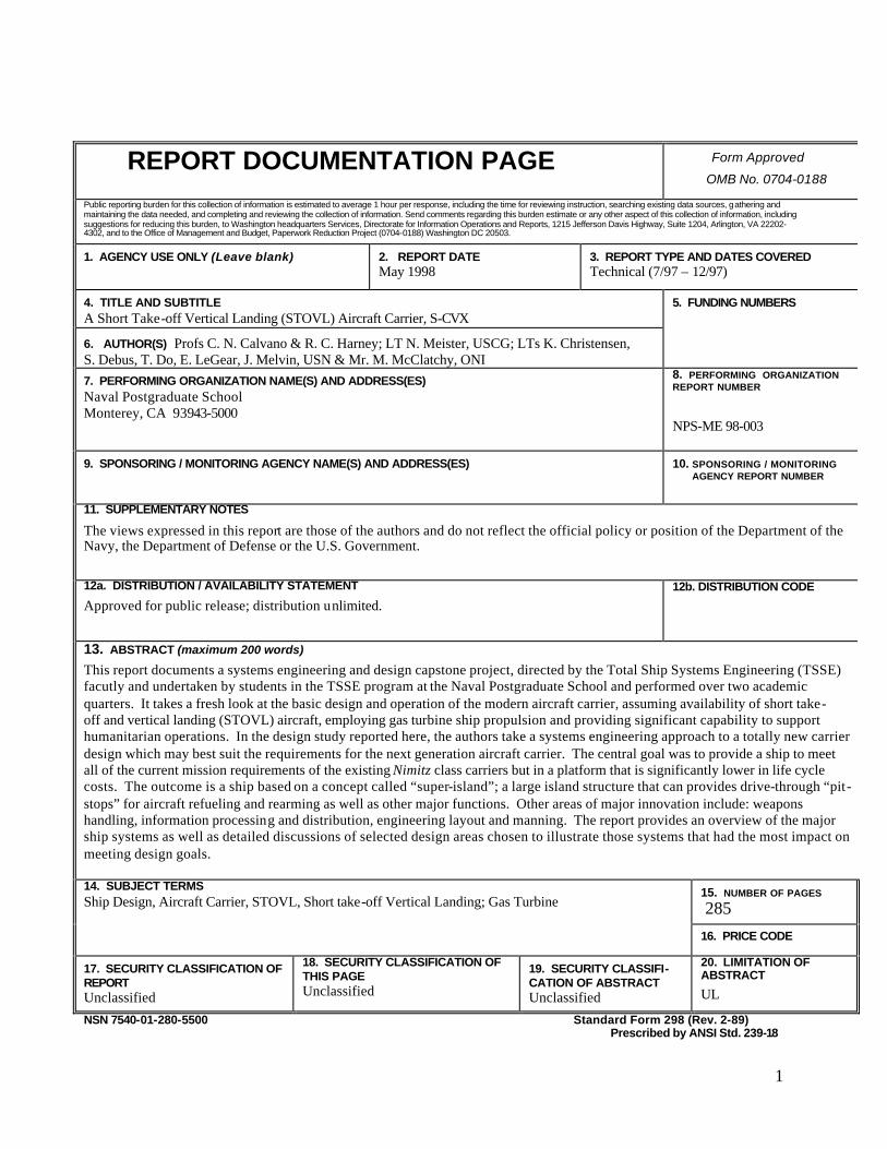
This report documents a systems engineering and design capstone project, directed by the Total Ship Systems Engineering (TSSE) facutly and undertaken by students in the TSSE program at the Naval Postgraduate School and performed over two academic quarters. It takes a fresh look at the basic design and operation of the modern aircraft carrier, assuming availability of short take-off and vertical landing (STOVL) aircraft, employing gas turbine ship propulsion and providing significant capability to support humanitarian operations. In the design study reported here, the authors take a systems engineering approach to a totally new carrier design which may best suit the requirements for the next generation aircraft carrier. The central goal was to provide a ship to meet all of the current mission requirements of the existing Nimitz class carriers but in a platform that is significantly lower in life cycle costs. The outcome is a ship based on a concept called “super-island”; a large island structure that can provides drive-through “pit-stops” for aircraft refueling and rearming as well as other major functions. Other areas of major innovation include: weapons handling, information processing and distribution, engineering layout and manning. The report provides an overview of the major ship systems as well as detailed discussions of selected design areas chosen to illustrate those systems that had the most impact on meeting design goals. 14. SUBJECT TERMS Ship Design, Aircraft Carrier, STOVL, Short take-off Vertical Landing; Gas Turbine
15. NUMBER OF PAGES 285
16. PRICE CODE
17. SECURITY CLASSIFICATION OF REPORT Unclassified
18. SECURITY CLASSIFICATION OF THIS PAGE Unclassified
19. SECURITY CLASSIFI- CATION OF ABSTRACT Unclassified
20. LIMITATION OF ABSTRACT
UL
NSN 7540-01-280-5500 Standard Form 298 (Rev. 2-89) Prescribed by ANSI Std. 239-18
2
A Short Take-off/Vertical Landing (STOVL) Aircraft Carrier
(S-CVX)
This report documents a systems engineering and design capstone project undertaken by students in the Total Ship Systems Engineering (TSSE) program at the United States Naval Postgraduate School and performed over two academic quarters. The project was under the direction of Professors C. N. Calvano and R. Harney. The design team consisted of: LT Neil Meister, USCG; LT Jim Melvin, USN; LT Thuy Do, USN; LT Eric Legear, USN, LT Kathryn Christensen, USN; LT Steve Debus, USN and Mr. Mike McClatchey, Office of Naval Intelligence.
ABSTRACT
In the era since World War II, the aircraft carrier has arguably been the type of naval combatant that has undergone the least innovation. With the end of the Cold War, the shift of focus from blue water engagements to littoral operations and the stark realities of fiscal conservatism, a fresh look at the basic design and operation of the modern aircraft carrier is warranted. In addition, major advances in computers and information systems, short take-off and vertical landing (STOVL) aircraft, automated handling systems and robotics provide new challenges and opportunities to the basic shape and functioning of the aircraft carrier. In the design study reported here, we examine these often conflicting constraints and technologies and by means of a systems engineering approach we offer a totally new carrier design which we feel best suits the requirements we were given for the next generation aircraft carrier. Our central goal in this design was to provide a ship that can meet all of the current mission requirements of the existing Nimitz class carriers but in a platform that is significantly cheaper in life cycle costs. The outcome of our effort is a ship based on a concept we call “super-island”; a large island structure that can provides drive-through “pit-stops” for aircraft refueling and rearming as well as other major functions. Other areas where we made major innovations include: weapons handling, information processing and distribution, engineering layout and manning.
Following an introduction, the first part of this document outlines the requirements which constrained our design. These requirements include both the prescribed requirements in our Mission Need Statement (MNS) as well as a list of derived requirements generated through our review of the MNS and other requirements documents. The second part of the report outlines the initial design decisions and trade-off analyses which led to our proposed ship. The final section of the report provides an overview of the major ship systems as well as detailed discussions of selected design areas. The sheer magnitude of an aircraft carrier design and the limited time frame available prohibit us from presenting detailed discussions of all design areas. The selected areas that are presented, however, are an attempt to present those systems that had the most impact on meeting our design goals.

3
Table of Contents List of Figures and Tables.................................................................................................................6
1 Introduction...............................................................................................................................8
2 Requirements ............................................................................................................................8
2.1 Mission Need Statement and Supplemental Guidance .........................................................8
2.2 Analysis and Implications ...................................................................................................25
2.2.1 STOVL / Emergency CTOL Capability .....................................................................25
2.2.2 Aircraft Weapons Load Out ........................................................................................25
2.2.3 Humanitarian Relief Capabilities................................................................................25
2.2.4 Gas Turbine Propulsion ..............................................................................................26
2.2.5 Decreased Manning.....................................................................................................26
2.3 Derived Requirements.........................................................................................................26
2.3.1 Airwing Mix................................................................................................................26
2.3.2 Landing Rate ...............................................................................................................29
3 Initial Design Decisions ..........................................................................................................30
3.1 Design Philosophy ..............................................................................................................30
3.1.1 Improved Flight Deck Operations ..............................................................................30
3.1.2 Automated Aviation Weapons Handling ....................................................................30
3.1.3 Increased Sortie Rate ..................................................................................................30
3.1.4 Reduced Signatures.....................................................................................................31
3.1.5 Life Cycle Affordability..............................................................................................31
3.2 Design Assumptions ...........................................................................................................31
3.2.1 Integrated Computer/Communication Network .........................................................31
3.2.2 Communications Suite ................................................................................................32
3.2.3 Self Defense Weapons System ...................................................................................32
3.3 Design Trade Spaces/Feasibility Studies ............................................................................32
3.3.1 Flight Deck Studies .....................................................................................................32
3.3.2 Hull, Mechanical and Electrical (HM&E) Studies .....................................................43
3.3.2 Combat Systems Studies .............................................................................................49
4.......................................................................................................................................................52
System / Ship Descriptions .............................................................................................................52

4
3.4 Arrangements of Selected Areas.........................................................................................52
4.1.1 Flight Deck Layout and Operations ............................................................................52
4.1.2 Hangar Deck Layout ...................................................................................................58
4.1.3 Humanitarian & Operations Other Than War (OOTW) Support ...............................59
4.1.4 Super-Island Arrangements.........................................................................................63
4.1.5 Bridge and Primary Flight Control and Engineering Operating Station (EOS)
Arrangements..........................................................................................................................65
Engineering Operating Station (EOS) Layout ........................................................................67
Carrier Information Center (CVIC) Layout ............................................................................68
4.2 Hull Design .........................................................................................................................69
4.2.2 Signature Reduction Efforts........................................................................................71
4.2.2 Passive Protection Systems .........................................................................................73
4.2.3 Magazine Design.........................................................................................................73
4.2.4 Tankage Design...........................................................................................................74
4.3 Ordnance Handling System ................................................................................................74
4.3.1 Assumptions................................................................................................................75
4.4 C4ISR Systems Descriptions ...............................................................................................79
4.4.1 Antenna Arrays ...........................................................................................................79
4.4.2 External Connectivity .................................................................................................80
4.4.3 Defense Systems .........................................................................................................84
4.4.4 Decoy and Deception Systems....................................................................................86
4.4.5 Mine Avoidance Sonar................................................................................................88
4.4.6 Computer and Communications Architecture ............................................................88
4.5 Hull Mechanical and Electrical (HM&E) Systems Design ................................................92
4.5.1 Integrated Power System ............................................................................................92
4.5.2 DC Zonal Electrical Distribution System ...................................................................93
4.5.3 Auxiliary Systems .......................................................................................................93
4.5.4 Propulsor System ........................................................................................................93
4.5.5 Power Analysis ...........................................................................................................94
4.5.6 Resistance Analysis .....................................................................................................94
4.6 Damage Control Design Efforts..........................................................................................94

5
4.6.1 Overview.....................................................................................................................94
4.6.2 Fire Suppression Systems ...........................................................................................95
4.6.3 DC Deck Location and Flooding Concerns ................................................................95
4.6.4 Chemical, Biological and Radiological Defense Systems .........................................96
4.7 Manning Analysis ...............................................................................................................96
4.8 Weight Reports ...................................................................................................................99
4.9 Naval Architecture Analysis .............................................................................................100
4.9.1 Body Plan..................................................................................................................100
4.9.2 Isometric View..........................................................................................................101
4.9.3 Section Area Curve ...................................................................................................101
4.9.4 Hydrostatic Properties at Level Trim........................................................................102
4.9.5 Floodable Length Curve ............................................................................................102
4.9.6 Intact Stability with Wind Heeling Arm...................................................................103
4.9.7 Intact Stability with Turn Heeling Arm....................................................................104
4.10 Cost Analysis ................................................................................................................104
4.10.1 Methodology ..............................................................................................................104
4.10.2 Results .......................................................................................................................105
4.11 Conclusions ..................................................................................................................108
4.12 Faculty Assessment of Major Design Innovations .......................................................109
5 References .............................................................................................................................113
6 Appendices............................................................................................................................115
Appendix A-1 Friendly and Hostile Force Structures for S-CVX Defining Scenario ............116
Appendix A-2 Scenario Mission Analysis and Required Aircraft Sorties for S-CVX Defining
Scenario .....................................................................................................................................118
Appendix B-1 Island- less Carrier Study..................................................................................123
Appendix C-1 Mine Avoidance Sonar Analysis.......................................................................128
Appendix C-2 TSSE S-CVX Baseline Manning ......................................................................130
Appendix C-3............................................................................................................................158
6
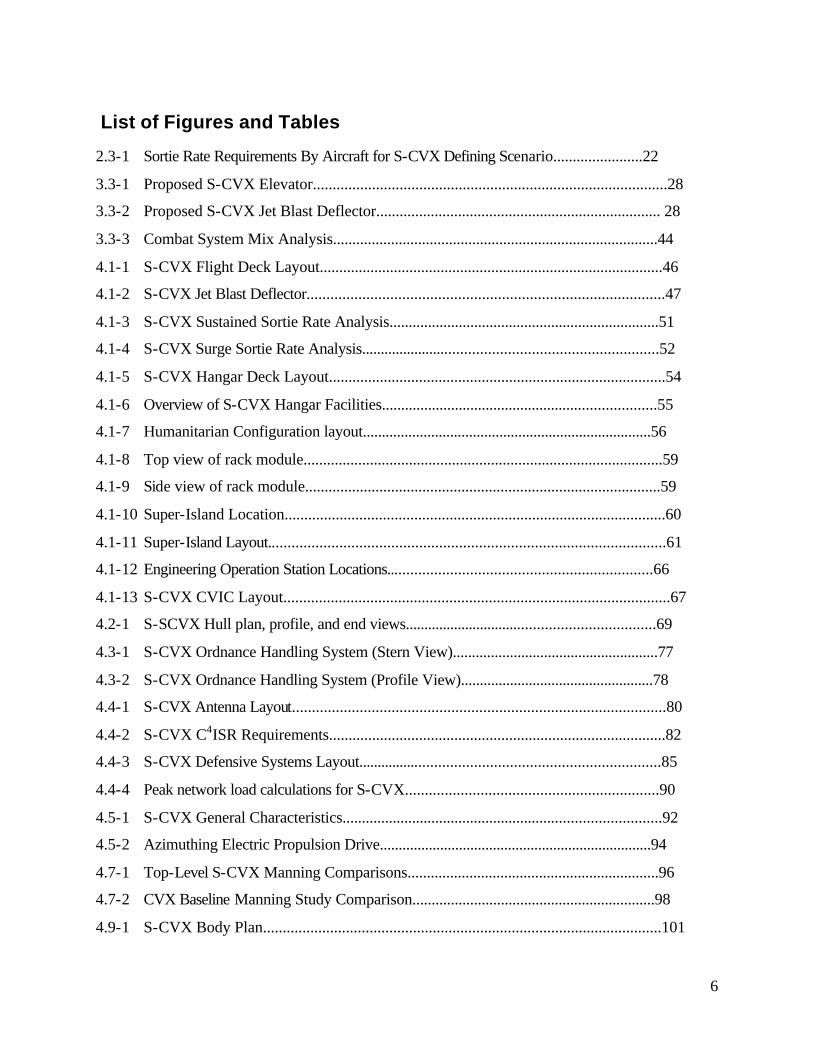
List of Figures and Tables
2.3-1 Sortie Rate Requirements By Aircraft for S-CVX Defining Scenario.......................22
3.3-1 Proposed S-CVX Elevator..........................................................................................28
3.3-2 Proposed S-CVX Jet Blast Deflector......................................................................... 28
3.3-3 Combat System Mix Analysis....................................................................................44
4.1-1 S-CVX Flight Deck Layout........................................................................................46
4.1-2 S-CVX Jet Blast Deflector..........................................................................................47
4.1-3 S-CVX Sustained Sortie Rate Analysis......................................................................51
4.1-4 S-CVX Surge Sortie Rate Analysis............................................................................52
4.1-5 S-CVX Hangar Deck Layout......................................................................................54
4.1-6 Overview of S-CVX Hangar Facilities.......................................................................55
4.1-7 Humanitarian Configuration layout............................................................................56
4.1-8 Top view of rack module............................................................................................59
4.1-9 Side view of rack module...........................................................................................59
4.1-10 Super-Island Location.................................................................................................60
4.1-11 Super-Island Layout....................................................................................................61
4.1-12 Engineering Operation Station Locations...................................................................66
4.1-13 S-CVX CVIC Layout..................................................................................................67
4.2-1 S-SCVX Hull plan, profile, and end views.................................................................69
4.3-1 S-CVX Ordnance Handling System (Stern View)......................................................77
4.3-2 S-CVX Ordnance Handling System (Profile View)...................................................78
4.4-1 S-CVX Antenna Layout..............................................................................................80
4.4-2 S-CVX C4ISR Requirements......................................................................................82
4.4-3 S-CVX Defensive Systems Layout.............................................................................85
4.4-4 Peak network load calculations for S-CVX................................................................90
4.5-1 S-CVX General Characteristics..................................................................................92
4.5-2 Azimuthing Electric Propulsion Drive........................................................................94
4.7-1 Top-Level S-CVX Manning Comparisons.................................................................96
4.7-2 CVX Baseline Manning Study Comparison...............................................................98
4.9-1 S-CVX Body Plan.....................................................................................................101

7
4.9-2 S-CVX Isometric view of hull..................................................................................102
4.9-3 S-CVX Section Area Curve......................................................................................102
4.9-4 S-CVX Hydrostatic Properties at level trim.............................................................103
4.9-5 Floodable Length Curve...........................................................................................103
4.9-6 Intact Stability with Wind Heeling Arm...................................................................104
4.9-7 Intact Stability with Turn Heeling Arm....................................................................105
4.10-1 S-CVX Cost Analysis...............................................................................................106
8
1 Introduction
In the year 2015, the USS Enterprise (CVN-65) is scheduled to retire from service.
Unless another carrier is built and ready to enter service on that date, the United States will fall
below the nation’s stated need of twelve carrier battlegroups. The easiest solution would be to
continue building Nimitz-class aircraft carriers. This, however, is rapidly becoming an
impractical solution. The Nimitz was designed for blue-water engagements between fleets and
long range (potentially nuclear) air strikes. The mission today is much more varied and focused
on the littorals. This Nimitz-class is also the most expensive ships in the fleet to procure and
operate. The challenge then is to reinvent the aircraft carrier to meet today’s mission needs at a
much more affordable life-cycle cost. The CVX Program Office is currently tasked with
resolving this dilemma. The 1997 student class in the Total Ship System Engineering (TSSE)
Program undertook to complete a design for the new carrier as our capstone design project. This
document is the product of our efforts. To avoid confusion, throughout this document we refer
to our resulting design as the Short Take-off and Vertical Landing (STOVL) CVX or S-CVX.
This reflects our use of a STOVL airwing and avoids confusion when referencing the Program
Office’s ongoing CVX design efforts.
2 Requirements
2.1 Mission Need Statement and Supplemental Guidance
At the start of this design effort the student team was presented with a Mission Need
Statement (MNS) and a sheet of Supplemental Faculty Guidance that delineated the requirements
of the design effort and provided boundaries for the scope of the task. These two documents are
provided below.
The intent was to provide a MNS which was as close as possible to the NAVSEA CVX
Mission Need Statement. Indeed, some paragraphs are copied verbatim. However, for reasons
given below, some changes had to be made. Many of the modified requirements contained in
these documents are neither obvious as to origin nor are they entirely consistent with the current
9
thoughts of the Navy’s CVX program office. The TSSE capstone design project is first and
foremost an educational experience for the students. Development of innovative concepts for
serious consideration by naval ship designers is desirable but secondary. Design of a ship that
will actually be built has never been a goal, although design realism is stressed throughout the
project. The faculty leaders of this project strove to create a project that would challenge the
students to think out of the box, to generate alternative approaches to problems with accepted
conventional solutions, and to address issues which may run contrary to the conventional party
line. The design presented herein was forced to address the faculty-provided guidance. Any
perceived shortfalls relative to a “practical” design that arise from the imposition of these
constraints are the fault of the faculty and not of the students.
Although the primary desire in developing the MNS and supplemental guidance was to
create a problem that was interesting & challenging, yet sufficiently bounded for a small design
team to tackle in a limited time frame, many of the requirements do have a rationale to them and
are not pulled from thin air. In some cases the rationale may simply be to reopen an issue that
has been declared settled (any good solution can always stand up favorably to further review). In
others, the faculty may feel that changes in technology or threats that have occurred since the
initial decisions were made warrant a revisiting of those decisions. In others the faculty may
simply disagree with the conventional solution path. In still others there is a desire to quantify
through design the implications of selecting an unconventional alternative. In the guidance
documents that follow, the faculty have added annotations in italicized typeface which document
their rationale. This rationale was not initially provided to the students, so as to avoid distraction
during the crucial initial steps in the project. However, most of it eventually became apparent as
a result of student questioning of various requirements.

10
In the remainder of this section, the italicized portions are faculty comments added
at the time of the printing of this report, which were not in the guidance provided to the
students at the beginning of the project.
MISSION NEED STATEMENT FOR A
TACTICAL AVIATION SHIP (CVX)
TS4002 7/15/97
1. Mission. The general missions of the Tactical Aviation Ship (CVX) are to:
(a) Perform missions currently assigned to Nimitz class carriers, and be interchangeable
with a Nimitz class ship in any battle group.
The CVX class carriers will begin replacing Nimitz class carriers on a one-for-one basis
as soon as they are introduced. Since the missions of the Nimitz class carriers are not
disappearing, it is essential that the replacement carriers have a minimum capability
which is comparable to the Nimitz class.
(b) Be much more adaptable to the littoral warfare environment likely to be encountered
in a Major Regional Conflict or in Operations Other than War (OOTW).
Current projections of the threat indicate a much reduced probability of blue water
engagements between U. S. carrier battle groups and either enemy surface action groups
or enemy carrier battle groups. Much more of the fighting will be conducted near the
coastlines of adversary nations. Because of the economic importance of littoral waters,
other nations may be more disposed to contesting shared littoral regions. In addition, the
reduction in the need to be able to forcibly maintain control of the seas coupled with our
desires to have operating forces in the forward areas, places naval forces in the position
of being available to perform other missions, such as peacekeeping or humanitarian
operations.
(c) Perform all missions independently of forward-based land facilities.
As the defense budget continues to shrink and as other nations feel the presence of U. S.
forces on their territories is not in their best interests, our access to forward bases will
continue to decrease. In times of hostilities, countries wishing to maintain a degree of
neutrality may close normal airfield and port facilities to our military forces. Any new

11
combatant must not require the existence of forward bases which may not exist when
needed.
2. Threat. The CVX battle group will face threats from
(a) nuclear and diesel submarines;
The magnitude of this threat has not changed, although ownership of assets has changed
considerably.
(b) long-range land-based aircraft, naval aviation, theater ballistic missiles, sea skimming
missiles, high speed high altitude cruise missiles, and mines. (Rockets and missiles are
assumed not to carry nuclear weapons, although chemical, biological, radiological
warheads and EMP (nuclear or conventional) are a possibility.);
Traditional threats have not disappeared. New threats such as ballistic missiles with
terminal guidance capable of hitting moving surface combatants are under development
(prior to the signing of the Intermediate Nuclear Forces treaty, the U. S. possessed an
intrinsic capability to perform this mission in the Pershing 2 weapon system). The
proliferation of weapons of mass destruction may result in their use against U. S. forces
in times of conflict (especially if the enemy is in possession of a strategic nuclear
retaliatory capability). The requirement to address all kinds of advanced warheads
(except nuclear) will result in a highly survivable design without attempting to solve the
virtually insoluble problem of hardening a ship against nuclear weapons exploded at
close range. Addressing radiological and EMP warheads will result in a ship capable of
surviving nuclear explosions more than a few kilometers distant.
(c) Surface ships ranging from cruiser-type ships to missile patrol boats and small craft;
(Organization of threat craft may vary from a disciplined surface action group, possibly
including a STOVL-aircraft-equipped carrier, to organized swarm attacks from smaller
vessels to kamikaze-type raids by individual small craft);
For the next few decades the U. S. will undoubtedly face foes pursuing asymmetrical
warfare. However, before the first CVX reaches its midlife point, at least one potential
adversary may have developed a blue water navy comparable to our own (by 2015 the
defense budget of China is expected to exceed that of the United States in real dollars).
(d) Naval special forces.

12
Special forces become most effective when their capabilities are underestimated and
adequate preparations are not made to resist them.
3. Capabilities. The primary function of the CVX is to shelter, transport, launch, recover and
maintain multi-mission tactical aircraft. The core capabilities required are:
(a) Strategic mobility - the ability to independently deploy/respond quickly and operate
with sufficient tactical flexibility, whenever and wherever required, to enable joint
maritime expeditionary force operations. The sustained speed will be 25 kts.
Although the MNS does not explicitly require gas turbine propulsion, the students were
strongly encouraged to use this technology in their design. Nuclear propulsion was
allowed, but only if gas turbines could be shown to be inadequate. One of the primary
advantages of nuclear carriers is their ability to transit any distance at high speed (30+
kts) and immediately engage the enemy. Although no conventionally powered carrier
can hope to equal this performance, the sustained speed and range requirements in (b)
below will permit the S-CVX to arrive within 4 days of a nuclear carrier’s arrival time
from any point on the globe with only one en-route refueling. San Diego to the Straits of
Hormuz is approx. 11,500 nmi. or 16 days at 30 kts for a nuclear carrier. The same
distance for the S-CVX can be covered in less than 20 days at 25 kts even with a half-day
stop for refueling. Transit time differences for Norfolk to the Straits of Hormuz via Suez
are only 2 days.
(b) Sustainability - it must have the capacity to sustain itself, its aircraft and escort for
extended periods without access to shore facilities. The ship will carry sufficient fuel for
16000 nm (at 20 kts) plus twice the air wing fuel carried by a Nimitz class carrier. The
ship must be able to refuel (at a limited rate) from any commercial tanker in an
emergency (limited to sea state 4 or less). Food and stores endurance will be equal to the
Nimitz class, except that emergency rations for 2500 persons for 30 days will be carried
in addition. Ordnance storage capacity will be 50% larger than that of the Nimitz class,
with one magazine capable of storing nuclear weapons.
One of the major arguments used against conventional (vice nuclear) carriers is that they
are incapable of transiting from home ports to operational areas at high speeds and
immediately engaging in combat operations without stopping to refuel (see above). This
13
can be ameliorated by forcing the design to accommodate an extra fuel load. An added
concern is that when operations are contemplated in littoral environments, the enemy
may be able to deny the unrestricted movement of resupply ships. For example, if the
carrier were operating in the Persian Gulf and a hostile power were to massively mine
the Straits of Hormuz, oilers and ammunition ships might be denied to the fleet for the
days to weeks it would take to clear the mines. A 2X reserve of bunker fuel, 2X reserve of
aviation fuel, and 1.5X reserve of ordnance would allow full combat operations to
continue for a number of days even if resupply was cut off. The ordnance and aviation
fuel reserves would also reduce the need for almost daily resupply when massive
operations are underway (as was often the case during the Vietnam war).and 1.5X
reserve of ordnance would allow full combat operations to continue for a number of days
even if resupply was cut off. The ordnance and aviation fuel reserves would also reduce
the need for frequent resupply when massive operations are underway (as was often the
case during the Vietnam war).
(c) Survivability - it must be able to operate aircraft in hostile environments, protect
itself from attack by threat weapons, and if hit, degrade gracefully and survive. The ship
must be capable of transit through any sea state (including hurricane/typhoon seas)
without suffering significant damage and be capable of launching/recovering aircraft
under the same conditions as a Nimitz class carrier. The ship will be capable of
withstanding at least one mine strike, one torpedo hit or two Harpoon-equivalent missile
impacts without sustaining damage which prevents flight operations; the ship will be
capable of withstanding hits from double the number of any of these threats (or any
appropriately ratioed combination of these hits) without sinking.
The mass of weaponry that can be brought to bear against any combatant operating in
littoral environments will almost guarantee some hits. A carrier for littoral warfare
must be capable of taking hits from any of the major littoral threats (mines, torpedoes,
cruise missiles) and continuing to fight or it will not be allowed to sail in harm’s way.
(d) Ability to deliver precise, high-volume firepower - it must be able to operate an air
wing of 60 aircraft, consisting of approximately 45 STOVL, 10 tiltrotor and 5 rotary
wing. Ordnance will consist of the versions available in 2015 of current programs,
including Joint Standoff Weapon (JSOW) with unitary, antiarmor submunition, and
14
cluster warheads, Joint Direct Attack Munition (JDAM), HARM, Harpoon, Sidewinder
and AMRAAM. Unmanned air vehicles may be utilized to perform some mission
functions.
With aircraft costs continuing to increase and defense budgets expected to continue to
decrease (or at least not increase significantly), the Navy will be unable to procure as
many aircraft as it has in the past. Carrier air wings will be smaller in the future. Wings
as small as 40 airplanes are being discussed. A 60-aircraft wing is intermediate between
today’s 80+ aircraft wings and the lowest number. A smaller airwing should
theoretically result in a smaller carrier with lower procurement and operational costs.
This would help to maintain a twelve carrier Navy in times of decreasing procurement
budgets. The approximate aircraft mix was selected to provide STOVL or VTOL
alternatives to each aircraft currently in the aggregate airwing on a carrier: STOVL
strike fighters instead of F/A-18’s; tiltrotor aircraft instead of S-3, C-2, E-2C, and EA-
6B support aircraft; rotary wing platforms comparable to existing platforms. Carrier
designs dedicated to handling only STOVL aircraft are often dismissed because the Navy
will have legacy CTOL aircraft for many years. However, the navy will have CTOL
aircraft carriers for many years after legacy aircraft have all been relegated to the
boneyard. Because of this less-than-logical objection, STOVL carrier designs have not
been investigated as thoroughly as they deserve. Another objection has been based on a
putative inability of STOVL aircraft to perform the support aircraft functions. The
faculty do not completely concur with this assessment. It is their belief that more
concerted design efforts incorporating new technologies (especially in sensors and
powerplants) will result in support aircraft designs that are adequate to perform their
roles, even if their performance may be less than current aircraft. The benefits of an all-
STOVL design may outweigh the penalties accrued to the support aircraft. This can only
be investigated by postulating the successful development of STOVL support aircraft and
proceeding with the carrier design. It is expected that cost and efficiency concerns will
result in a rather limited selection of basic weapon types with variants to accommodate
different mission requirements. This “standardization” should facilitate automation of
weapons handling with subsequent important savings in required manpower. Unmanned
air vehicles will be increasingly used by the military of the future. If functions currently
15
performed by manned aircraft can be adequately performed by unmanned air vehicles,
their use should be encouraged and facilitated. This will allow the reduced number of
manned aircraft assets to concentrate on those tasks that they alone can perform.
(e) Joint command and control - it must be interoperable and its communications suite
must be fully compatible with other naval, expeditionary, interagency, joint, and allied
forces. In addition, it must be able to operate as a Command and Control center, integrate
information to develop a coherent tactical picture to support Joint Force, Battle Force,
Battle Group and Air Wing planning, coordinate actions with other forces, and
communicate the force's actions to appropriate commanders. The ship must have the
capability to fully support a Joint Force Commander (JFC) and under limited
circumstances be able to host an embarked JFC. Connectivity must include seamless
integration of both organic and off-ship sensor inputs for power projection actions.
Aircraft carriers are key components of any major command. As such they may be
employed in many roles, coupled with many other kinds of forces. Connectivity must be
assured with any and all of the other forces with which they must operate. Dedicated
Command & Control centers such as shore installations or Command & Control ships
may not always be available. The aircraft carrier is the obvious choice among
combatant vessels for serving as the force Command & Control center, regardless of
force size or composition, including a Joint Force Command.
(f) Flexibility and growth potential - it must have the versatility to support current and
future sea-based STOVL aircraft. It must have the ability to perform simultaneous multi-
mission taskings and readily adapt to changing operational needs. In addition, it must
have the flexibility to adapt to changes in future threats, missions and technologies.
Just as the missions assigned to carrier aviation and aircraft carriers have changed
substantially in the 50 years since World War II, they will likely change even more
radically in the 50 years of operational life of the new carriers. To the extent practical,
the carrier must not be prevented from, or hindered in, performing these new and
unplanned missions by avoidable design choices. Technology and threat capabilities will
also significantly improve over the life of the carrier. The design must facilitate rapid
and cost-controlled incorporation of new technologies and new defensive weaponry as
they become available.
16
(g) Humanitarian Operations and OOTW – The ship will provide empty shelter space for
accommodating as many as 2500 non-combatants in an emergency (this space may be
used for crew recreation or enhanced survivability; it must not interfere with the ability of
the ship to conduct normal functions, even with the additional passenger load onboard).
Freshwater and sanitation systems must support the crew plus non-combatants for a 30
day period. Meals may be accommodated from the emergency rations required in
paragraph 3(b).
It is possible that humanitarian operations will become one of the major missions of the
Navy. Because of the size of an aircraft carrier, it becomes the obvious (and possibly
only suitable) candidate for housing large numbers of non-combatants such as might
become necessary during a Noncombatant Evacuation Operation or during relief of
islands devastated by hurricanes, typhoons, or volcanic eruptions. Although this was not
anticipated at the time this document was generated, the student design is amenable to
allowing the carrier to be used as an emergency hospital ship facility (without halting
combat operations) – a mission now being discussed for CVX.
4. Constraints.
(a) Architecture. The ship design must employ a total ship, aircraft and weapons system
architecture/engineering approach that optimizes life cycle cost and performance; permits
rapid upgrade and change in response to evolving operational requirements; allows
computational and communications resources to keep technological pace with
commercial capabilities and allows for full realization of the command, control,
communications, computers, and intelligence (C4I) for the warrior (C4IFTW) concept;
and provides the capability to survive and fight hurt. More specifically this implies
physical element modularity; functional sharing of hardware (across all services); open
systems information architecture; shipwide resource management; automation of
Command, Control, Communications, and Computers (C4I), combat, aircraft support,
ordnance handling, management; automation and minimization of maintenance and
administrative functions; integrated systems security; and embedded training. The
approach should also promote commonality with other ship designs. The ship will have a
low observable design with radar signatures (to sea skimming missiles at all ranges and to
17
high altitude missiles at 50 km range), infrared signatures and acoustic signatures that are
no larger than those of a DD963 class ship. Design trade studies will include at least one
concept which does not have an “island”.
Most of this paragraph is good systems engineering practice and common sense and
requires no further justification. Commonality with other ship designs is desirable
because it should promote reduced construction costs. Signature reduction is desirable
in any new design. Since it is impossible to make a ship as large as an aircraft carrier
invisible to sensors in multiple frequency bands, the next best step is to make it
indistinguishable from its many escorts (thus the choice of a relatively small ship as a
comparison standard). Cruise missiles are seen as the primary threat in the radar
spectrum, although both sea-skimming and high-altitude diving missile designs may be
encountered. Radar cross section reduction is more difficult if multiple aspects must be
considered. Overhead radar assets (radar ocean reconnaissance satellites or terminal
seekers on ballistic missiles) were not included as it is virtually impossible to obtain a
low radar cross section at normal incidence to a very large, flat flight deck. As the island
is a major source of aircraft carrier radar cross section and infrared signature, the
faculty wished to see if the island could be completely eliminated in a fully functional
design.
(b) Design. Consideration should be given to the maximum use of modular construction
design in the ship’s infrastructure. Emerging technologies must be accounted for during
the developmental phase. Modern, flexible information processing must be built into any
new weapons system. Since communication and data systems hold the greatest potential
for growth, and therefore obsolescence, their installations must be modularized as much
as possible to allow for future upgrades. Use standard man-to-machine interfaces among
the systems onboard.
Modular design considerations and pre-planned growth paths may eliminate the costly
and lengthy mid-life upgrade aircraft carriers currently undergo by allowing minor
upgrades every time the ship returns to home port.
(c) Personnel. The platform should be automated to a sufficient degree to realize
significant manpower reductions in engineering, damage control, combat systems, ship
support and Condition III watchstanding requirements. Reduced manning concepts used
18
by other Navies should be reviewed to leverage advanced technologies and future
advanced technology concepts in an effort to minimize shipboard manning requirements.
Preventive maintenance manpower requirements must be reduced by incorporating self-
analysis features in equipment designs, and by selecting materials and preservatives
which minimize corrosion. Tradeoffs which reduce Manpower, Personnel and Training
(MPT) requirements will be favored during design and development. It is especially
desired to minimize or entirely eliminate the need for flight deck personnel. Total crew
size (including the air wing) will be less than half that of a Nimitz class carrier
(including air wing). The ship will be cashless and paperless.
Manpower is one of the largest contributors to life cycle cost of any ship acquisition. As
a consequence, Pareto analysis suggests that vigorously attempting to reduce manpower
is one of the best ways to reduce life cycle cost. Naval manpower levels are also likely to
continue to decrease as defense budgets shrink (or even remain static). Ship manning
must decrease or the permissible number of ships will decrease. Prior estimates of
achievable manpower reductions on CVX did not predict achievable reductions that
would have any dramatic effect on life cycle costs. Examination of these studies
indicated that a lack of significant reductions in airwing manpower and less than
aggressive incorporation of manpower-saving technology were major contributors to the
limited manpower reductions achieved. To force a total reassessment of this problem,
the faculty arbitrarily set a goal of a maximum of 50% manpower relative to a Nimitz
class carrier including the airwing. Flight deck personnel are significant limiters of
sustained combat operations. These positions are also among the most hazardous on an
aircraft carrier. When the added safety concerns associated with the extreme power of
the STOVL JSF engines are considered, it makes sense to attempt to totally eliminate
flight deck personnel, if practical. SMARTship has shown that cashless and paperless
ships are practical. This will likely be a requirement of all new Navy ship designs.
(d) Aircraft. Aircraft will have footprints and fuel consumption comparable to planned
JSF STOVL aircraft and existing V-22 and SH-60 aircraft. The CVX must be able to
perform all mission functions using the airwing addressed in paragraph 3(d); novel
concepts must be developed to permit some mission functions (such as AEW) to be
accommodated; no additional manned aircraft will be permitted to perform any function.
19
The faculty expect that all three of these aircraft (JSF, V-22, and SH-60) will be available
in air wing quantities by 2015. They further expect that the V-22 will undergo at least
one major improvement (probably re-engining) to provide improved range, payload, and
fuel efficiency. Budgetary concerns will limit the number of new aircraft programs that
will begin in the next few decades. The Common Support Aircraft postulated by
conventional CVX proponents may be one of the many potential new starts that does not
occur in a timely fashion. The faculty believe that aircraft like the V-22 can be adapted
to fulfill many of the support missions if requirements are scrubbed to the bare minimums
and innovative concepts are developed for the mission equipment packages. For
example, if fuel tanks and a crew-controllable refueling drogue are incorporated into the
V-22 cargo spaces, that aircraft can refuel a substantial quantity of JSFs. The somewhat
reduced airspeed of the V-22 is a limitation, but not an overwhelming one (if a KC-10
can refuel an MH-53D in flight, a V-22 can refuel a JSF, even a damaged one). Similar
solutions can be envisioned for anti-submarine warfare, airborne early warning,
electronic countermeasures, and carrier on-board delivery. There is also a possibility of
performing some missions using unmanned air vehicles. Although the faculty recognize
that some performance penalties may be incurred by forcing an all STOVL solution, they
also recognize that the Navy may not be able to afford more Nimitz-like conventional
carriers in addition to several new classes of aircraft.
(e) Sortie generation. Given at least 40 flightworthy aircraft and at least twice that
number of qualified flight crews, the CVX shall be capable of indefinitely maintaining a
fixed-wing sortie generation rate of 160/day, surging to 240 sorties/day for a period of 48
hours. The CVX must be capable of turning around (taxiing, repairing all electronic
failures, refueling, rearming, pre-flight inspecting and preparing for takeoff) any and all
fixed wing aircraft within one hour of their touchdown, even at surge sortie generation
rates. The ship must be capable of launching at least two aircraft simultaneously and
capable of launching eight ready aircraft within ten minutes.
Recent exercises have demonstrated that a Nimitz-class carrier with an 80 aircraft air
wing with extra flight crews can maintain 160 sorties/day for extended periods and surge
to 240 sorties/day. It is desired that CVX maintain at least the Nimitz-class capability
20
even though the number of aircraft in the airwing is reduced. To facilitate these rates,
rapid aircraft turnaround and rapid launch rates must be achievable.
(f) Other. The CVX must be capable of trapping any fleet aircraft in an emergency, as
well as providing refueling and one-time take-off capability for those aircraft. The ship
will employ gas turbine propulsion, using the same fuel for air wing and ship propulsion.
Although the CVX in this study will carry only STOVL aircraft in its airwing, there will
be some carriers in the fleet which will still be flying conventional take-off and landing
(CTOL) aircraft. In a major conflict more than one carrier may be operating in a theater
and because of the prior interchangeability requirement, the second carrier may be
CTOL. Should that second carrier be sunk or severely damaged, it is desirable to be able
to prevent the loss of otherwise undamaged aircraft and aircrews by providing for the
emergency landing and take-off of CTOL assets. Although most studies indicate that
nuclear propulsion is superior to conventional propulsion, many of these studies are
based on comparison between existing carrier designs. The faculty wished to determine
if a design specifically tailored to overcome the usually stated drawbacks (excessive size
and/or inability to transit and engage without resupply) could be achieved. Once a
conventional power plant is mandated it makes sense to permit the captain the option to
trade maneuver for flight operations and vice versa (remember in a STOVL carrier, it is
not essential to always steam into the wind to accommodate flight operations). Use of a
common fuel permits this flexibility.
(g) The CVX IOC will be 2015.
This is consistent with current CVX requirements.
5. Operational Constraints
(a) The CVX must remain fully functional and operational in all environments
regardless of time of day, whether conducting independent or force operations, in heavy
weather or in the presence of electromagnetic, nuclear, biological and chemical
contamination and/or shock effects from nuclear and conventional weapon attack.
The ship must be survivable and not suffer a mission kill from any of these threats. The
list goes beyond Navy survivability policy (OPNAVINST 9070.1 dated 23 Sept 1988) by
including chemical and biological contamination. The faculty feel that aircraft carriers
21
are exceedingly tempting targets for chemical and biological attack due to the large
numbers of personnel on current flight decks and the large, virtually uncleanable hangar
spaces. Chemical or biological contamination would be difficult to remove and flight
operations would slow to a standstill if all flight, flight deck, and hangar deck personnel
were required to wear MOPP 4 gear for an extended period. In many areas of the world
it would be virtually impossible to prevent contamination if a suicide attack were
executed. Due to continuing proliferation of chemical and biological weapons, they are
currently possessed in substantial quantities by most nations which are potentially hostile
to the United States.
(b) The CVX must meet the survivability requirements of Level III as defined in
OPNAVINST 9070.1. Topside systems components shall be decontaminated through use
of a countermeasure wash down system and portable Decontamination (DECON)
methods.
This requirement is the minimum consistent with the comments of 5(a) above.
(c) The CVX must provide landing and hangar facilities, and ammunition storage for
operational support of required aviation assets.
(d) The ship must be able to operate in U.S., foreign, and international waters in full
compliance with existing U.S. and international pollution control laws and regulations.
The students were encouraged to provide hangar space for all aircraft. This eliminates a
major source of radar and infrared signatures since even stealthy aircraft have large
signatures with their wheels down. Hangaring aircraft would also significantly reduce
corrosion problems and associated maintenance. However, hangar space for all aircraft
was not treated as an absolute requirement.
(e) All ship and combat system elements must make use of standard subsystems and
meet required development practices. The CVX must be fully integrated with other U.S.
Navy, Marine Corps, joint and allied forces, and other agencies (e.g., Theater Air
Defense Architecture) in combined, coordinated operations. For example, linkage with
standard data bases from the Defense Mapping Agency (DMA) will minimize ancillary
costs and promote maximum interoperability with the widest number of weapons and

22
sensor systems. Joint goals for standardization and interoperability will be achieved to the
maximum feasible extent.
These fairly straightforward requirements were levied on the students to force them to
ascertain what standardization and interoperability goals are currently being considered
(f) The ship must be able to embark Special Operations Forces (SOF) and Joint Forces
when required for selected missions.
(g) The CVX, when part of a battle group, will be accompanied by at least two Aegis
class cruisers or destroyers, one or more nuclear attack submarines and other surface
combatants.
It is virtually impossible and certainly inefficient to design any ship to be capable of
performing every naval mission on a stand-alone basis. Air defense (against cruise
missiles and ballistic missiles) and anti-submarine warfare are more efficiently
conducted from specialized platforms. Since any aircraft carrier is subject to missile and
submarine attack, it is reasonable to off-load the defenses against those threats to
specialized escort platforms.

23
Supplemental Faculty Guidance
MISSION NEED STATEMENT FOR A
TACTICAL AVIATION SHIP (CVX)
TS4002 7/15/97
1. The guidance provided herein is intended to supplement or expand on the information in the
draft Mission Need Statement of the same date.
2. The MNS specifies an air wing of 60 aircraft, with an approximate breakdown. One of the
studies you should do is to determine the optimum mix among these aircraft types. If unmanned
air vehicles are used, they may be in addition to the 60, unless they exceed 10 in number or they
require significantly more deck space. The tradeoffs involved must be included in the aircraft
mix study.
The 45 STOVL/10 tiltrotor/5 rotary wing mix was merely an educated guess on the part of the
faculty. The optimum mix in any carrier wing depends on the missions to be performed. Some
time after the promulgation of this document, the faculty specified that the air wing mix be
determined from a mission analysis of a very stressing mission: support of an amphibious
invasion of a fortified coastline using a single carrier without any nearby supporting land bases
as one element of a major regional conflict. Bandar y Abbas in Iran was specified as the target
and reasonable projections of Iranian force levels were provided.
3. The MNS calls for the CVX to be able to trap and take off any fleet carrier aircraft in an
emergency. You should explore options to meet this need which minimize the impact on the
design of what will be, essentially, a STOVL carrier.
It is obvious that a conventional flight deck carrier can handle both STOVL and CTOL aircraft.
The faculty wanted the students to design a STOVL flight deck carrier that incidentally could
handle CTOL emergencies
4. When examining the required sortie rates assume a sortie consists of a take-off-to-touch-down
duration of 2.5 hours.
This is roughly the amount of time required to fly a strike mission on targets at 400 nm range.
24
5. In examining ways to minimize manpower, explore the concept of “wing-level” maintenance,
with all aircraft logistics and maintenance functions organized at the carrier air wing, rather than
the squadron, level.
Currently each squadron assigned to an air wing has its own organic maintenance unit. When
almost a dozen kinds of aircraft are carried on the carrier, this has merit. However, when the
number of aircraft types is reduced to three, it makes less sense. Why have three separate
maintenance teams and shops to service three squadrons of identical JSF aircraft? Manpower
and support equipment can be reduced in a wing maintenance concept (if only a few aircraft
types exist in the wing).
6. In examining a ship design without an island, you will need to address and develop viable
concepts for monitoring flight deck operations, navigation under high traffic conditions,
communications and radar/electronic warfare operations.
These are all functions currently requiring elevated locations on the island. They are still
required so an alternative means of performing them must be devised.
A Faculty Assessment of Design Innovation appears at the end of this report, on page 109.
25
2.2 Analysis and Implications
2.2.1 STOVL / Emergency CTOL Capability
The MNS calls for the basic airwing to be fully STOVL capable while the ship still
retains the capability for emergency landing and launching CTOL aircraft from legacy aircraft
carriers. This allows us to examine elimination of the catapult and arresting gear systems. The
embarked STOVL aircraft should present no problems with eliminating the catapults. The only
remaining issue is whether or not the emergency CTOL launch capability can be achieved
without catapults. In the Future Aircraft Carrier Study performed by the Naval Air Engineering
Center [1] it was shown that the F/A-18 using a 6 degree ramp can take-off at maximum weight
with only a 400 foot roll out. Assuming this to be our worst-case-need roll out, it shows that
eliminating the catapults is indeed feasible. With regard to the arresting gear, no known
alternative exists for trapping multiple CTOL aircraft even on an infrequent basis. Thus the
arresting gear will have to be retained.
2.2.2 Aircraft Weapons Load Out
The MNS calls for the S-CVX to be capable of carrying versions available in 2015 of all
current aircraft weapons programs and goes on to list many of the weapons this should include.
Based on discussions we had with G-3 Division supervisory personnel on board U.S.S. Nimitz,
we noted that all of the weapons explicitly listed either currently exist as or expected to be “all
up rounds.” By this we mean that the weapons arrive in a shipping canister fully assembled and
fused and require no physical assembly prior to use. Iron bombs, by contrast, require a great deal
of assembly prior to use. One of our major initiatives in this study was to examine an automated
weapons handing system. To ease our analysis we did not consider standard iron bombs. If iron
bombs are still to be used on S-CVX we assume that they would be used much less often
(requiring fewer to be stored on ship) and those that are needed could come pre-assembled and in
canisters.
2.2.3 Humanitarian Relief Capabilities
Owing to the changing nature of expected operations, the MNS calls for the S-CVX to be
capable of accommodating 2500 non-combatants for 30 days and provide emergency rations and
26
sanitation services for these people. Obviously adding permanent berthing and services for such
a large, seldom-encountered, contingent would lead to a very inefficient ship design. Instead we
must devise a means to reuse existing parts of the ship temporarily. The challenge is to minimize
the impact the loss of this space has on full combat operations. Our requirements state that we
must at least maintain “normal” functions during this period. We interpret this to mean at least
the ability to maintain a full defensive posture while maintaining as much offensive capability as
possible. The main area where we expect to take degradation is in aircraft cycle throughput.
2.2.4 Gas Turbine Propulsion
In order to limit the scope of our study and examine alternatives to the current nuclear
propulsion option, the MNS forces us to select gas turbines for our propulsion system. This
selection also opens many other possible variations of the standard propulsion layout including
electric dive, engine locations, and propulsor type.
2.2.5 Decreased Manning
The MNS levies a requirement that the S-CVX manning (including airwing) must be less
than 50% of the current Nimitz manning (including airwing). Several of our other requirements
assist in meeting this manning goal. First, by not having nuclear power, we can significantly
decrease the engineering manning requirements. Secondly, large numbers of flight deck
personnel are involved with catapults and arresting gear operations. The requirement for a
STOVL airwing gives us the potential to eliminate the catapults entirely and requires operation
of the arresting gear only on an emergency basis for landing CTOL aircraft. Since this will be an
ad-hoc evolution, we could eliminate dedicated personnel for this effort and rely on cross
training of other crew members. More details of our manning analysis are presented in section
4.7.
2.3 Derived Requirements
2.3.1 Airwing Mix
The MNS lists a firm upper bound of 60 aircraft for the airwing size and provides a
notional breakout for the mix between JSFs (45), V-22s (10) and SH-60s (5). One of our tasks
was to validate or modify this notional airwing mix or to justify changes. To do this we

27
generated what we considered to be a worst-case for S-CVX aircraft utilization. The proposed
scenario is one in which an S-CVX carrier battle group must support an expeditionary force
amphibious landing in southern Iran. The year is 2020, and Iran has launched a massive invasion
of its southern neighbors. The tactical situation is that the defending forces (Arab nations and
US forces) have halted the initial Iranian invasion forces. These friendly forces and a CV battle
group (in central Arabian Gulf) are busy halting southward flow of Iranian troops and aircraft.
The strategic objective is to halt the invasion by Iran and then eliminate its capabilities to repeat
such aggression at any point in the succeeding ten years. The tactical objective of the S-CVX
battle group is to enable the landing of a brigade-sized expeditionary force in southern Iran. This
force must seize and hold a major port facility (Bandar-E-Abbas) to facilitate debarking
conventional infantry forces and equipment in preparation for a major land offensive. Friendly
and hostile force structure and composition are listed in appendix A-1.
During the scenario, S-CVX aircraft must be capable of performing these minimum
operations: anti-submarine warfare (ASW), anti-surface warfare (ASUW), offensive counter-air
(OCA), and strike operations. An iterative analysis of the scenario concluded that an air-wing
composition of 45 JSFs, 10 V-22s, and 5 SH-60s was sufficient to perform all scenario
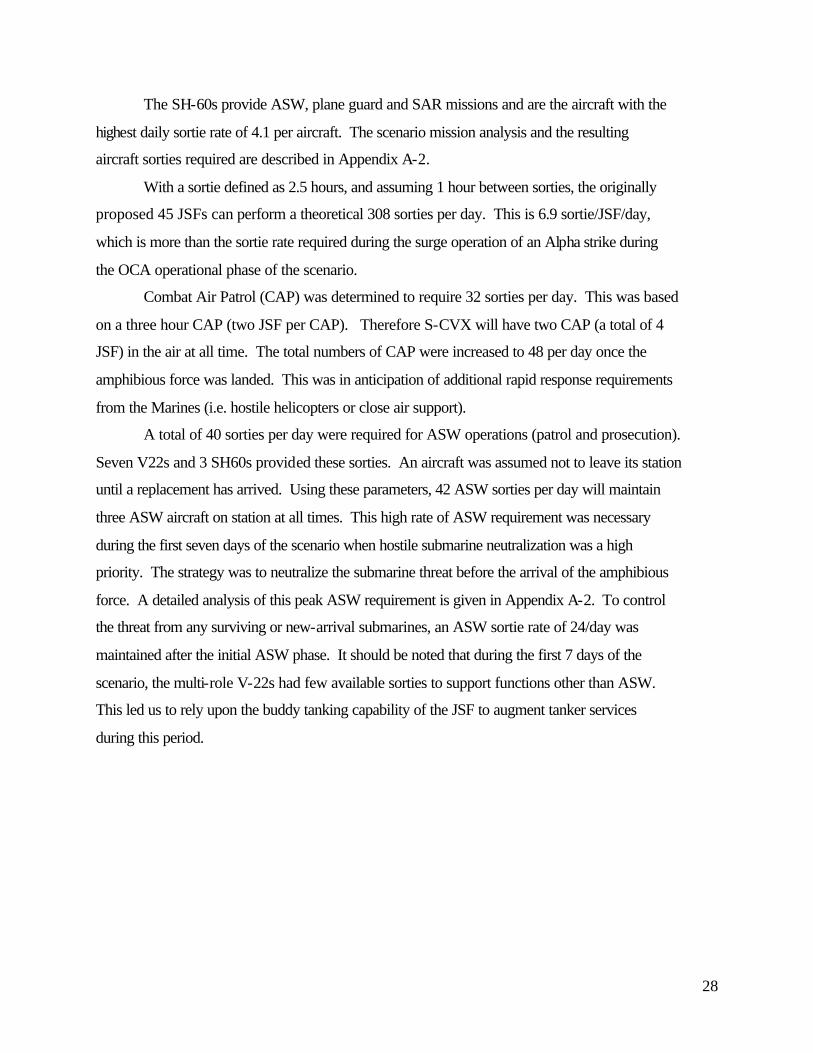
requirements. Table 2.3-1 describes the sortie rate for each aircraft in the different missions of
the scenario. The actual peak sortie rates occur during the OCA operations, requiring 215 sorties.
A minimum of 45 JSFs is required to perform the OCA operation. Three V-22s will be
configured as AEW platforms and the other 7 V-22s will be multi-role support aircraft,
performing ASW, tanker, and COD missions. To perform these disparate functions, we envision
the V-22 payload bay being redesigned with different “plug and play” modules. These modules
are end loaded in the rear of the aircraft and could even include the rear door/loading ramp on the
V-22. The three modules required are:
• an ASW electronics suite including rear ejected sonobouys (ASW torpedoes would be
wing mounted or rear ejected)
• an airborne tanking module containing a drogue/probe reel-able tanking system and extra
fuel tanks
• a cargo/transport module with extra seats and tie down points.
28
The SH-60s provide ASW, plane guard and SAR missions and are the aircraft with the
highest daily sortie rate of 4.1 per aircraft. The scenario mission analysis and the resulting
aircraft sorties required are described in Appendix A-2.
With a sortie defined as 2.5 hours, and assuming 1 hour between sorties, the originally
proposed 45 JSFs can perform a theoretical 308 sorties per day. This is 6.9 sortie/JSF/day,
which is more than the sortie rate required during the surge operation of an Alpha strike during
the OCA operational phase of the scenario.
Combat Air Patrol (CAP) was determined to require 32 sorties per day. This was based
on a three hour CAP (two JSF per CAP). Therefore S-CVX will have two CAP (a total of 4
JSF) in the air at all time. The total numbers of CAP were increased to 48 per day once the
amphibious force was landed. This was in anticipation of additional rapid response requirements
from the Marines (i.e. hostile helicopters or close air support).
A total of 40 sorties per day were required for ASW operations (patrol and prosecution).
Seven V22s and 3 SH60s provided these sorties. An aircraft was assumed not to leave its station
until a replacement has arrived. Using these parameters, 42 ASW sorties per day will maintain
three ASW aircraft on station at all times. This high rate of ASW requirement was necessary
during the first seven days of the scenario when hostile submarine neutralization was a high
priority. The strategy was to neutralize the submarine threat before the arrival of the amphibious
force. A detailed analysis of this peak ASW requirement is given in Appendix A-2. To control
the threat from any surviving or new-arrival submarines, an ASW sortie rate of 24/day was
maintained after the initial ASW phase. It should be noted that during the first 7 days of the
scenario, the multi-role V-22s had few available sorties to support functions other than ASW.
This led us to rely upon the buddy tanking capability of the JSF to augment tanker services
during this period.
29
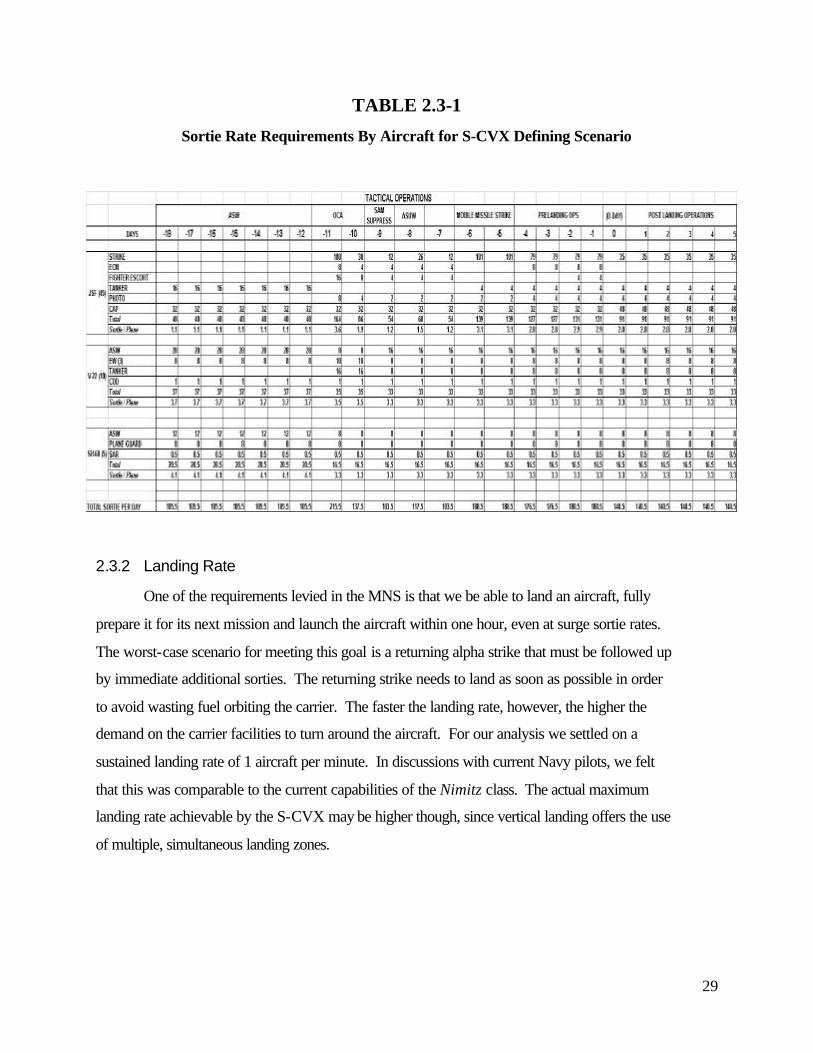
TABLE 2.3-1
Sortie Rate Requirements By Aircraft for S-CVX Defining Scenario
2.3.2 Landing Rate
One of the requirements levied in the MNS is that we be able to land an aircraft, fully
prepare it for its next mission and launch the aircraft within one hour, even at surge sortie rates.
The worst-case scenario for meeting this goal is a returning alpha strike that must be followed up
by immediate additional sorties. The returning strike needs to land as soon as possible in order
to avoid wasting fuel orbiting the carrier. The faster the landing rate, however, the higher the
demand on the carrier facilities to turn around the aircraft. For our analysis we settled on a
sustained landing rate of 1 aircraft per minute. In discussions with current Navy pilots, we felt
that this was comparable to the current capabilities of the Nimitz class. The actual maximum
landing rate achievable by the S-CVX may be higher though, since vertical landing offers the use
of multiple, simultaneous landing zones.
30
3 Initial Design Decisions
3.1 Design Philosophy
The top level objective of this project is to explore the feasibility and conduct a
conceptual design of a U. S. Navy Tactical Aviation Ship designed around Short Take
Off/Vertical Landing (STOVL) aircraft, specifically the STOVL version of the Joint Strike
Fighter (JSF). Due to the complexity of an aircraft carrier design and the limited manning and
time frame of this project, not all areas will be examined with the same level of detail. After
reviewing our MNS, we decided to concentrate our design efforts on the following issues:
3.1.1 Improved Flight Deck Operations
Current flight deck operations are extremely manpower intensive, fraught with personnel
hazards and not necessarily efficient. With the introduction of the Joint Strike Fighter (JSF) to
the airwing, an additional safety hazard (excessive engine noise) must now be overcome. It is
predicted that the JSF engine noise will be loud enough to cause physical injuries to personnel in
its immediate vicinity who are not equipped with active noise cancellation protection and body
armor. We believe that this new danger poses an undue burden on personnel safety and
efficiency in completing traditional flight deck operations. For this reason, one of our major
design initiatives is to eliminate the need for exposed personnel on the flight deck.
3.1.2 Automated Aviation Weapons Handling
Beyond flight deck operations, the next most manpower intensive activity on an aircraft
carrier is the handling of aviation weapons. In order to achieve our reduced manning
requirements, this is an area that must be addressed. The CVN 76 Workload Analysis and CVX
Baseline Analysis Initial Manning Estimate [2], proposed several initiatives on how to automate
the weapons handling process. For our project, we undertook better definition of these
automated systems to assess their possible impacts on manning and tactical operations.
3.1.3 Increased Sortie Rate
When military planners of today and the foreseeable future factor in an aircraft carrier to
their plans, they are assuming a ship with the capabilities of the Nimitz class. Since CVX and by
31
extension our S-CVX is supposed to be a one-for-one replacement of the retiring large deck
aircraft carriers we must be able to match or exceed the sortie rate of the Nimitz.
3.1.4 Reduced Signatures
Modern, high technology anti-ship missiles, mines, and torpedoes are becoming
increasingly available to third world nations. With these nations representing the bulk of
potential threats in the littoral environment, more needs to be done to protect our ships against
these threats. Per our requirements in the MNS, we strive to reduce the signatures (radar,
infrared and acoustic) of S-CVX to the level of an existing Spruance class destroyer (a ship
about one tenth the projected displacement of our design for S-CVX).
3.1.5 Life Cycle Affordability
The entering argument for all ship designs in the new era of budget cuts is life cycle
affordability. This is especially true for the CVX program. The Nimitz class aircraft carriers are
a proven effective design but they are also extremely expensive to build and operate. Therefore
all of our design efforts in S-CVX must strive to decrease life cycle costs and produce a more
affordable ship.
3.2 Design Assumptions
In several areas time constraints, lack of technical resources and other factors limited the
scope of our design efforts. In these areas we either found other Navy studies relevant to the
issue and extrapolated information as needed or we found information regarding the Navy’s
current trends and accepted the results at face value.
3.2.1 Integrated Computer/Communication Network
All new construction ship designs within the Navy are utilizing Fiber Optic backbones
with Asynchronous Transfer Mode (ATM) protocols. These designs have been migrating much
of the current point to point copper communications for tactical systems as well as ship
monitoring and control onto the networks. We plan to continue this trend and expand it to
include adding voice communications and ship’s entertainment systems to the network as well
(currently this is done in separate networks). The ATM format was designed with full
multimedia (voice, video and data). The commercial industry is already moving towards fully
32
integrated ATM networks and we are confident that this technology will be mature by in time for
use in S-CVX. In order to size and layout the network topology of the S-CVX
Computer/Communications Network we relied heavily upon studies performed by the New
Attack Submarine (NSSN) program in 1994-1995 [3] [4] [5] [6].
3.2.2 Communications Suite
For our design we plan to accept Navy’s current Copernicus design initiatives for
communications suite equipment. Our design only assumes that by 2015 a great deal more
automation will be achieved to allow reduced manning in the system.
3.2.3 Self Defense Weapons System
The Navy’s self defense weapons system of the future is the Evolved Sea Sparrow
Missile (ESSM) [7]. After consultations with the program office designing the system we
concluded that this system would meet our self protection needs and be ready in time for the
ship.
3.3 Design Trade Spaces/Feasibility Studies
As part of the design process we examined several areas in detail to develop a set of
optional trade spaces from which to choose. These options were then compared against one
another and the best choice for that design area was selected for incorporation in the final ship.
It should be noted, however, that these early studies and decisions were sometimes expectedly
modified during later stages of the process as greater understanding of the overall ship design
was acquired. The following sections detail the feasibility studies conducted and their results.
Section 4 of the report then expands on these design decisions (and any needed changes) with
regard to the final ship.
3.3.1 Flight Deck Studies
In investigating the design feasibility of an aircraft carrier, we found that the flight deck
arrangement is the one variable that lends itself most to manipulation. To ensure the viability of
our ASSET ship design model, we constrained ourselves to exploring only monohull designs,
thus eliminating the need to study alternate hull forms. This decision was bostered by our belief
33
that departure from the monohull form offered no significant advantages. This then let us
devote most of efforts into designing alternate flight deck arrangements.
For a first order look, we began with a 1000 ft x 250 ft rectangle (Nimitz equivalent flight
deck size) and started to layout the features that all the designs would have in common [8];
• Take-off area JSF: two 450 ft runs, one 750 ft run
V-22/SH-60: 100 ft diameter dedicated VTOL area
CTOL: 850-1000 ft w/ski jump (JATO assist as required)
• Landing areas JSF: 60 ft diameter Jet Blast Collectors (see below)
V-22/SH-60: 100 ft diameter dedicated VTOL are
CTOL: 800 ft run-out w/three arresting engines
• Pit stops JSF: five required
V-22/SH-60: one required
• Gas turbine inlet/exhaust locations
four gas turbines
• Elevators 60 ft x 70 ft, handles all aircraft (see below)
• Ski-jump
This led us to three alternative layouts that we investigated in more detail:
1. Longitudinal Super Island
2. Athwartships Island
3. Island-less
Further study found that two requirements are the primary drivers for the overall size of
the carrier. One is the requirement to launch and recover Conventional Take-off and Landing
(CTOL) aircraft on an emergency basis. This immediately drives the minimum length of the
carrier out to 800 feet to accommodate the arrested run-out of legacy aircraft. The other is the
requirement to hangar all aircraft below decks (65 total); the current carriers only hangar 40-50
percent (less than 40 total). This requirement alone would make the ship at least 1000 feet long
to accommodate this huge hangar.
All of the designs we studied have the following attributes in common;

34
1. Pit Stops: We completed an aircraft flow-through study to determine the minimum
number of pit stops required to meet the most demanding mission requirement, the
alpha strike. Our initial study suggested that five JSF pit stops are needed to handle
an alpha strike with a maximum aircraft turn-around time of one hour. Therefore all
of our designs include five JSF pit stops and one V-22/SH-60 pit stop (further
analysis later reduced the required number of JSF pit stops to four and allowed us to
eliminate the dedicated V-22/SH-60 pit stop and this is described further in section
4.1.1). All pit stops will be serviced with weapons from below in the weapons
gallery.
2. Elevators: The elevators are located on the deck-edge, but are completely enclosed
outboard to help reduce signature. They do not travel vertically in the trunk, but
operate at an angle to match the flare of the sponsons. They are sized at 60 ft x 70 ft
to accommodate two JSFs or SH-60s per lift or one V-22 on diagonal with no
overhang.
Figure 3.3-1 Proposed S-CVX Elevator
3. Jet Blast Collectors: The JSF will land vertically on the carrier and it is estimated that
the jet blast from the engine will require a minimum safe distance of 90 feet around the
aircraft as it lands. This places a serious constraint around each landing zone which
slows aircraft recovery. Each landing zone will have a 60 foot diameter jet blast collector
that has a flow-through grid structure on the deck which covers an exhaust collector
below. This will collect and safely vector the thrust overboard keeping the flight deck jet
blast free.
Hangar
Elevator Trunk
Flight Deck Gallery

35
Jet Blast ç
Overboardç
Figure 3.3-2 Proposed S-CVX Jet Blast Collector
Design Alternative Characteristics Evaluated
We evaluated three alternative designs at the feasibility study level. They are described below:
3.3.1.1 Longitudinal Super Island Design
Design features:
• 1000 ft x 250 ft flight deck
• 680 ft x 80 ft Super Island which starts 300 ft aft of bow, offset 20 ft to port to allow
proper CTOL landing area.
• Four elevators total, two each side with access to forward and aft segregated hangars.
• Starboard of island is STOVL launch area, two 450 ft runs and one 750 ft run, all
backed by Jet Blast Deflectors (JBDs). A twelve degree ski jump is located at the
bow with all take off runs aligned to its center.
• Starboard side is also the CTOL landing area with an 800 ft x 100 ft landing run out,
three arresting wires and ship’s engines are located aft. The long deck run (1000 ft)
and ski jump precludes the need for catapults to launch CTOL aircraft; any additional
thrust required may be provided by JATO rockets.
The Super Island houses all ship and air control spaces. Two engine rooms with two
large IPS gas turbines (LM 6000 or bigger) are located 350 feet apart just aft of the control
Grid
Exhaust
Flight Deck
36
spaces and just forward of the V-22/SH-60 pit stop. Five fully enclosed JSF pit stops and one V-
22/SH-60 pit stop are also housed in the island.
To the port side of the island, three JSF vertical landing zones (60 ft diameter) with JBCs
allow direct access to the pit stops and quick access to the elevators servicing both hangars.
Port forward of the bridge is a safe parking area for up to 15 aircraft.
The aft flight deck (120 ft x 250 ft) is a VTOL operating area with two 100 ft diameter
simultaneous launch and recover circles and direct access to the VTOL pit stop.
Two hangars, one forward and one aft, are segregated in the middle. Each hangar is
serviced by two elevators, one from each side of the ship. The space between the hangars houses
the weapons service elevator from the magazines.
Design Advantages:
• Fully enclosing pit stops in the island provide significant weather, acoustic, and weapons/jet
blast protection during rearm, refuel, flight line repair and pilot change out evolutions. No
personnel are required on the flight deck. The enclosure also provides capability to use an
overhead gantry crane for refueling and service. Smooth flow of aircraft from landing zone,
to rearm/refuel, to launch run is permitted.
• Aligning pit stops along the center line enhances the use of a race track style weapons
distribution system on the weapons gallery deck located immediately beneath the pit stops.
The weapons will be loaded on to the aircraft from below.
• Enhanced survivability through wide dispersal of prime movers, segregated hangars and
multiple elevators servicing each hangar.
• Locating prime movers in the island eliminates long intake and exhaust ducting runs which
consume large amounts of internal volume and cause engine performance loss. Exhaust
gases and acoustic emissions are directed up and away from aircraft and personnel.
• Enclosing elevators reduces radar signature.
• Simultaneous launch and recovery of aircraft is easily accommodated.
• Clear view of all ship and aircraft control evolutions is afforded, as is large amounts of high
up, unencumbered real estate on top of island for antennas and self defense weapons.
37
Design Drawbacks
• Increased radar signature due to large size of island.
• Reduced survivability of prime movers due to high up and exposed location.
• Additional structure leading to higher initial and life cycle maintenance costs.
3.3.1.2 Athwartship Super Island Design
Design Features:
• 850 ft x 250 ft flight deck
• Three elevators (can hold 2 of any aircraft)
• Two 750 ft STOVL take off
• Two 450 ft STOVL take off
• Three Jet Blast Collector JSF landing zones
• Two V-22 landing zones
• Three covered JSF pit stops, four exposed JSF pit stops
• Starboard of island is 850 ft x 100 ft CTOL landing zone
• Two sets of two engines (125 ft apart) are mounted on the island with no ducting
requirements
• Flight deck is 50 ft above water line, 12 degree ramp should help with A/C take off
Pit Stops:
• Cylindrical feed design (should be faster than race track design and also should avoid any
congestion problems. It would be a parallel flow vice serial flow design)
• Two independent pit stop areas should enhance survivability
• The covered pit stops would allow fueling from above, exposed pit stop would not.
• The center of each circular pit stop area can be a rotating disk that can quickly connect the
aircraft to each pit stop. The aircraft can also be moved to each pit stop on its own with the
TowBot (described elsewhere). This design feature should allow rapid movement of A/C to
pit stops and require less landing zones.
38
• The three covered pit stops are safe for personnel to move around. Three of the four outdoor
pit stops fall within the 150 ft danger zone (outboard take off lane.)
• The three covered pit stops (assume 20 min turn around time) should easily support normal
cyclic operations. High tempo operation would require the use of outdoor pit stops. Body
armor may be required by pilots at the outdoor pitting area. Pilots should be exposed only
for a short period of time for crew change out. Furthermore the very unique situation of a
complete A-strike turn around may be done by landing all A/C, servicing them, and then
taking off again.
• ** A second iteration of this design would raise the island by 10 ft and would allow a
complete indoor V-22 servicing station that does not require the V-22 to be folded.
Hangars:
• Two level hangars
• Total hangar area of 113,200 square ft.
• Upper hangar has three elevators
• Lower hangar has two elevators.
• Total hangar area could be smaller because current design has two large maintenance area,
aircraft are not parked on the elevators or in the indoor pit stop.
Design Advantages:
• Less RCS
Side Area Frontal Area
Athwartship Island 45092 sq ft 14450 sq ft
Longitudinal Island 70792 sq ft 15400 sq ft
No Island 48592 sq ft 12100 sq ft
• A smaller overall ship
• More total pit stops
• Direct and short A/C movements
• Engine placements required minimal ducting and also reduces IR signature
• Second iteration may have indoor non-folding V-22 servicing area

39
Design Concerns:
• Ship may have to be lengthened to get more efficient speed design
• Outdoor pit stop may be a safety concern
• Current flight deck can only hold 42 JSF on deck for A-Strike, the other 3 JSF will have to
be standing by below.
ATHWARTSHIP ISLAND
JSF
Unfolded V22
Folded V22
Folded SH60
Maintenance ShopLower Hangar
Upper Hangar
17 A/C
43 A/C
JSF External PitJSF LZ
JSF LZ0
V22 LZ JSF Internal PitV22 Internal Pit
V22 Landing Zone
Sonic Safe Line
Hangar
850 ft
Pre-Alfa Strike A/C Arrangement
250 ft
100 ft
130 ft
40
3.3.1.3 Island-less Design
The island-less design reduces radar cross section by removing the island used on current
Navy designs. The four main functions that had to be relocated in order to remove the island
were: ship control, the antenna farm, flight deck control/observation and engine inlet/exhaust.
Appendix B-1 provides more details on our analysis of these areas and potential alternatives.
The driving design factor for the island-less design was that in order for the pit stops to not be
enclosed they needed to be located 150 ft from any place a JSF may have an engine on (takeoff
or landing zone). This is due to the requirement for body armor inside a 150 ft radius. By
keeping the pit stops 150 ft away minor repairs and pilot change out can occur at the pit stop.
Our studies analyzed two variants of the island-less carrier: a large ship about the size of a Nimitz
class carrier and a smaller ship roughly the size of an old Midway class carrier.
Large Variant
Design Features :
• Approximate 1000ft by 300 ft flight deck.
• Four Gas Turbine inlets port side aft, exhaust blows off stern.
• Six pit stops (flush with deck, not enclosed) on port side.
• Four elevators, two port and two starboard.
• Four JSF landing zones and two V-22/helicopter landing zones.
• An enclosed antenna mast (radar cross section friendly -- similar to the one considered for
SC-21) on the port side aft.
• Camera mount amidships on the stern to view flight deck operations.
• Pilot house located centerline under the bow of the ship.
• Hangar deck area is 91000 square feet.
• Two 400 ft runways for “light” JSF
• One 750 ft runway for “heavy” JSF
• CTOL landing of 800ft by 120 ft is supported.
Positive Aspects of Design:
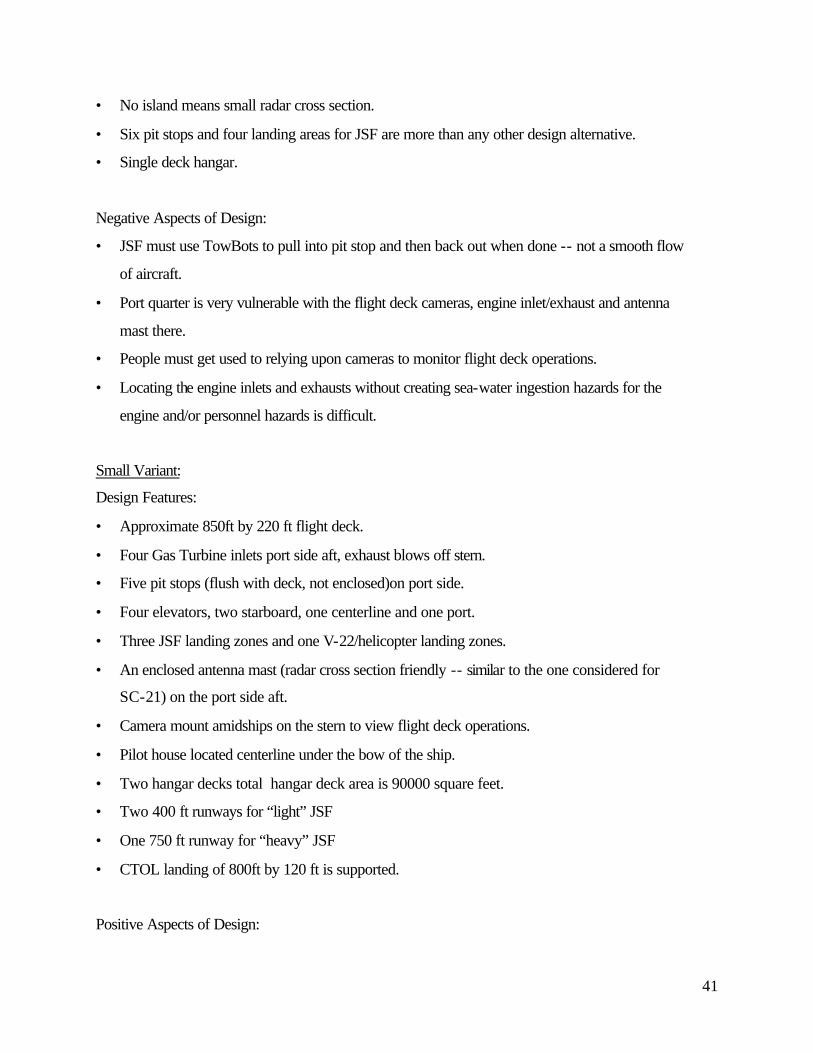
41
• No island means small radar cross section.
• Six pit stops and four landing areas for JSF are more than any other design alternative.
• Single deck hangar.
Negative Aspects of Design:
• JSF must use TowBots to pull into pit stop and then back out when done -- not a smooth flow
of aircraft.
• Port quarter is very vulnerable with the flight deck cameras, engine inlet/exhaust and antenna
mast there.
• People must get used to relying upon cameras to monitor flight deck operations.
• Locating the engine inlets and exhausts without creating sea-water ingestion hazards for the
engine and/or personnel hazards is difficult.
Small Variant:
Design Features:
• Approximate 850ft by 220 ft flight deck.
• Four Gas Turbine inlets port side aft, exhaust blows off stern.
• Five pit stops (flush with deck, not enclosed)on port side.
• Four elevators, two starboard, one centerline and one port.
• Three JSF landing zones and one V-22/helicopter landing zones.
• An enclosed antenna mast (radar cross section friendly -- similar to the one considered for
SC-21) on the port side aft.
• Camera mount amidships on the stern to view flight deck operations.
• Pilot house located centerline under the bow of the ship.
• Two hangar decks total hangar deck area is 90000 square feet.
• Two 400 ft runways for “light” JSF
• One 750 ft runway for “heavy” JSF
• CTOL landing of 800ft by 120 ft is supported.
Positive Aspects of Design:
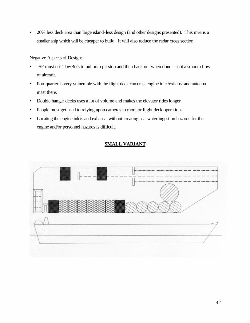
42
• 20% less deck area than large island-less design (and other designs presented). This means a
smaller ship which will be cheaper to build. It will also reduce the radar cross section.
Negative Aspects of Design:
• JSF must use TowBots to pull into pit stop and then back out when done -- not a smooth flow
of aircraft.
• Port quarter is very vulnerable with the flight deck cameras, engine inlet/exhaust and antenna
mast there.
• Double hangar decks uses a lot of volume and makes the elevator rides longer.
• People must get used to relying upon cameras to monitor flight deck operations.
• Locating the engine inlets and exhausts without creating sea-water ingestion hazards for the
engine and/or personnel hazards is difficult.
SMALL VARIANT
43
3.3.1.4 Selected Option and Rationale
After evaluation, we chose the Longitudinal Super Island design for further development.
The key factors in this decision were the ability to refuel/rearm aircraft in a fully enclosed
location and good aircraft flow from landing through servicing and take-off. We were greatly
encouraged, however, that the Athwartship Super Island and Small Island-less designs were able
to meet the needed requirements with a ship significantly smaller than the Nimitz. For our final
design we undertook modifying the Longitudinal Super Island design to also meet a maximum
ship length of 850 feet. This in turn forced several changes which will be explained later.
3.3.2 Hull, Mechanical and Electrical (HM&E) Studies
There are numerous HM&E alternatives that provide satisfactory solutions prescribed by
the Mission Need Statement (MNS). The most feasible alternatives are described below and are
subcategorized into hull, engines, drive train, propulsor, and electrical distribution.
3.3.2.1 Hull
Three types of hulls were considered feasible: Single Monohull, Advanced Double
Monohull, and a combination of the two.
3.3.2.2 Single Monohull
Single monohull ships are built with traditional transverse frames and longitudinal
stiffeners. Among the advantages are the facts that the single monohull has been previously
tested on US aircraft carriers and there is knowledge in the industry of how to build this type of
hull. A disadvantage of this hull form is that the required method of fabrication is fairly
expensive.
3.3.2.2.1 Advanced Double Monohull
Advanced double monohull ships are constructed with inner and outer hulls connected by
longitudinal web members. Studies into this design are currently part of a project funded by the
Office of Naval Research (ONR) with involvement from the ship building industry. The
potential advantages of this design are: improved resistance to underwater explosions, improved
damage control, and improved resistance to grounding damage. The biggest disadvantage of the
advanced double monohull is that the manufacturing process has not been tested [9].
44
3.3.2.2.2 Combination Single and Double Monohull
A hybrid single and double monohull ship utilizes the traditional single hull design
throughout most of the ship, but incorporates double hull structure in critical areas. The critical
areas to be housed within the double hull structure include all weapons magazines and machinery
rooms. This design incorporates the best of both hull features while mitigating their
disadvantages [10].
3.3.2.2.3 Hull Selection
The combination of single/double hull was selected. The improved survivability gained
through the double hulled design in key areas was the major factor in the selection. A complete
double hull design was not opted for principally two reasons: accompanying loss of internal
volume and technology risk.
3.3.2.3 Main Engines
The MNS dictates the use of gas turbine engines for propulsion achieving 25 knots
(sustained), which yields a requirement for 28 knots (maximum). Using scaling laws provided as
part of our TSSE curriculum [11] and assuming S-CVX has a displacement of 75,000 metric
tons, 112 megawatts (150,000 horsepower) are needed to propel S-CVX to 28 knots. In
addition, the CVX program AOA states that a 60 plane air wing will need 32 megawatts (43,000
horsepower) of electrical power [12]. Thus, a total of 144 megawatts (193,000 horsepower) of
power are need from the prime movers. The most feasible gas turbines are described below:
3.3.2.3.1 LM2500 (20 megawatts, 27,000 horsepower)
The LM2500 is the current gas turbine engine used by US Navy and other navies around
the world. Its advantages include long engine life, a well tested track record throughout the
world, and its relatively small intakes and exhausts. The LM2500’s disadvantages are its
relatively low power and old (1960's) technology.
3.3.2.3.2 LM6000 (45 megawatts, 60,000 horsepower)
The LM6000 represents the latest version of marine gas turbine from General Electric
and incorporates the latest technological advances. The major advantage of the LM6000 over
the LM2500 is its increased power with equal efficiency. The disadvantages for this engine
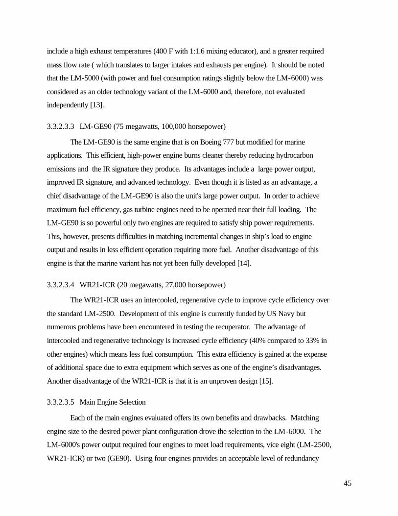
45
include a high exhaust temperatures (400 F with 1:1.6 mixing educator), and a greater required
mass flow rate ( which translates to larger intakes and exhausts per engine). It should be noted
that the LM-5000 (with power and fuel consumption ratings slightly below the LM-6000) was
considered as an older technology variant of the LM-6000 and, therefore, not evaluated
independently [13].
3.3.2.3.3 LM-GE90 (75 megawatts, 100,000 horsepower)
The LM-GE90 is the same engine that is on Boeing 777 but modified for marine
applications. This efficient, high-power engine burns cleaner thereby reducing hydrocarbon
emissions and the IR signature they produce. Its advantages include a large power output,
improved IR signature, and advanced technology. Even though it is listed as an advantage, a
chief disadvantage of the LM-GE90 is also the unit's large power output. In order to achieve
maximum fuel efficiency, gas turbine engines need to be operated near their full loading. The
LM-GE90 is so powerful only two engines are required to satisfy ship power requirements.
This, however, presents difficulties in matching incremental changes in ship’s load to engine
output and results in less efficient operation requiring more fuel. Another disadvantage of this
engine is that the marine variant has not yet been fully developed [14].
3.3.2.3.4 WR21-ICR (20 megawatts, 27,000 horsepower)
The WR21-ICR uses an intercooled, regenerative cycle to improve cycle efficiency over
the standard LM-2500. Development of this engine is currently funded by US Navy but
numerous problems have been encountered in testing the recuperator. The advantage of
intercooled and regenerative technology is increased cycle efficiency (40% compared to 33% in
other engines) which means less fuel consumption. This extra efficiency is gained at the expense
of additional space due to extra equipment which serves as one of the engine’s disadvantages.
Another disadvantage of the WR21-ICR is that it is an unproven design [15].
3.3.2.3.5 Main Engine Selection
Each of the main engines evaluated offers its own benefits and drawbacks. Matching
engine size to the desired power plant configuration drove the selection to the LM-6000. The
LM-6000's power output required four engines to meet load requirements, vice eight (LM-2500,
WR21-ICR) or two (GE90). Using four engines provides an acceptable level of redundancy
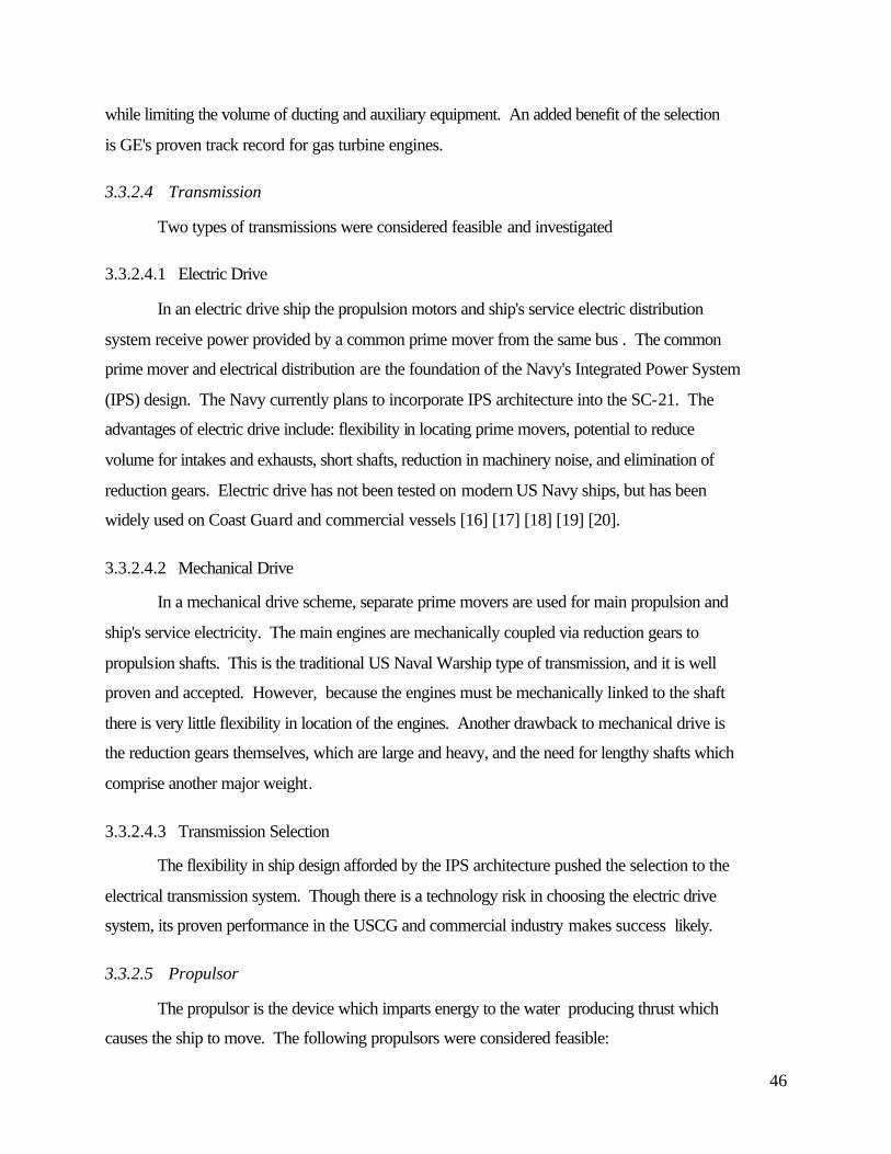
46
while limiting the volume of ducting and auxiliary equipment. An added benefit of the selection
is GE's proven track record for gas turbine engines.
3.3.2.4 Transmission
Two types of transmissions were considered feasible and investigated
3.3.2.4.1 Electric Drive
In an electric drive ship the propulsion motors and ship's service electric distribution
system receive power provided by a common prime mover from the same bus . The common
prime mover and electrical distribution are the foundation of the Navy's Integrated Power System
(IPS) design. The Navy currently plans to incorporate IPS architecture into the SC-21. The
advantages of electric drive include: flexibility in locating prime movers, potential to reduce
volume for intakes and exhausts, short shafts, reduction in machinery noise, and elimination of
reduction gears. Electric drive has not been tested on modern US Navy ships, but has been
widely used on Coast Guard and commercial vessels [16] [17] [18] [19] [20].
3.3.2.4.2 Mechanical Drive
In a mechanical drive scheme, separate prime movers are used for main propulsion and
ship's service electricity. The main engines are mechanically coupled via reduction gears to
propulsion shafts. This is the traditional US Naval Warship type of transmission, and it is well
proven and accepted. However, because the engines must be mechanically linked to the shaft
there is very little flexibility in location of the engines. Another drawback to mechanical drive is
the reduction gears themselves, which are large and heavy, and the need for lengthy shafts which
comprise another major weight.
3.3.2.4.3 Transmission Selection
The flexibility in ship design afforded by the IPS architecture pushed the selection to the
electrical transmission system. Though there is a technology risk in choosing the electric drive
system, its proven performance in the USCG and commercial industry makes success likely.
3.3.2.5 Propulsor
The propulsor is the device which imparts energy to the water producing thrust which
causes the ship to move. The following propulsors were considered feasible:

47
3.3.2.5.1 Fixed Pitch Propeller (FPP)
Fixed Pitch Propellers have been used on numerous naval vessels. FPP are well tested,
relatively cheap, and require smaller shafts (compared to the CRP described below).
Disadvantages of FPP include a narrow speed-efficiency range and poor reverse performance
[21].
3.3.2.5.2 Controllable Pitch Propeller (CRP)
Controllable Pitch Propellers alter pitch of the propeller blades for a given shaft speed in
order to maximize efficiency in both the forward and reverse directions. CRP's are the standard
for modern Navy Surface combatants, excluding carriers. Disadvantages of this design include:
increased size of shaft, increased maintenance due to complex hydraulic system, and cost.
3.3.2.5.3 Fixed Pods
Pods are extensions outside of the ship's hull that house a motor which turns a fixed pitch
propeller (FPP). Due to the external configuration of their design, pods necessarily require
electric drive transmission. Fixed Pods have been built up to 40 megawatts and are currently
used for commercial applications. The external arrangement provides a better flow field which
increases propulsive efficiency. This arrangement also eliminates the need for long shafts.
Disadvantages to the fixed pod design include increased navigational draft they create, the need
for cooling air, and a limited stopping/reverse direction capability [22].
3.3.2.5.4 Azimuthing Pods
Azimuthing pods have all the advantages of fixed pods, but provide greatly improved
maneuverability. Because the pods can rotate 360°, ship turn radius and stopping distance are
both reduced. Rotating pods eliminate the need for rudders and thrusters, thus decreasing
appendage resistance and increasing propulsive coefficient (PC). There are some disadvantages
to azimuthing pods. To date the largest pod to be built for commercial application is 25
megawatts. In addition, structural testing of the hull-pod mount may be required in order to meet
Navy ship shock criteria [23].
3.3.2.5.5 Water Jet

48
Water jets use an axial flow pump and nozzle to propel vessels. They have been used in
commercial applications up to 20 megawatts; however most water jets are used in lower power
applications. Water jets transmit less noise into the water than propellers. They have never been
tested on a ship as large as the S-CVX and thus their feasibility is questionable [24].
3.3.2.5.6 Propulsor Selection
Of the propulsor options considered, only the CRP and azimuthing pod can possibly
provide both the power and maneuverability required for a vessel as large as the S-CVX.
Though the CRP is the accepted Navy standard, the azimuthing pod offers much greater
flexibility of internal arrangements and is also likely to provide better maneuverability. There is
an acknowledged technological risk in selecting the pod, however, the structural testing and
motor improvements necessary should be obtainable over the next ten to fifteen years. Further,
the full benefits of the IPS electric transmission architecture may be realized with this selection.
3.3.2.6 Electrical Distribution
All ship's systems that require electrical power are connected to the electrical distribution
network. The network includes all necessary power conditioning circuits, breakers, electric
energy storage, switchboards, and electric wire cabling.
3.3.2.6.1 Conventional Electrical Distribution System
The standard Navy electrical distribution system consists of 60 Hz, 400 Hz, and DC
transmission lines throughout the ship. Breakers, switchboards, and transfer stations are
centrally located. Electricity is derived from a mechanical power take-off connected to a high
speed alternator and cyclo-converter. Due to the multiple electrical current requirements and the
centralized location, long and heavy cable runs exist throughout the ship. The central location of
electrical equipment also presents inherent vulnerability risks: a casualty in one compartment my
affect numerous others.
3.3.2.6.2 DC Zonal Electrical Distribution (ZED) System
The DC ZED is a major component of the integrated power system (IPS) that is
designated to be installed in SC-21. Electricity is derived from a more affordable electrical
power take-off (common electrical bus) via a solid state power converter system. The ship is

49
divided into port and starboard federated zones, 1000 volt DC electricity for each zone is
provided via a power conversion module (PCM). Within each zone additional solid state PCMs
are installed to provide the necessary electrical requirements, e.g., 60 Hz or 400 Hz. Control and
status monitoring of each zone may be performed locally or centrally via the Standard
Monitoring and Control System (SMCS). Using DC distribution eliminates the need for large
electromechanical switchgear by utilizing power electronics and semi-conductor technology.
Another advantage achieved through the DC ZED is the decoupling of the main engine generator
frequency and the ship service operation frequencies. By separating the two, the generator is
able to operate at its most efficient frequency [25].
3.3.2.6.3 Electrical Distribution Selection
The Navy's 21st century combatants will use the DC ZED. With all the benefits
described above and its likely use as the future Navy standard, the S-CVX will incorporate the
DC ZED.
3.3.2 Combat Systems Studies
In our initial feasibility studies for the S-CVX combat systems, we attempted to examine
the gamut of potential threats the carrier could be presented with and then identified several
levels of organic and non-organic capabilities that could be used to defend against these threats.
Table 3.3-3 describes our analysis and provides the recommendations for which level of defense
should be implemented on S-CVX.
For all air threats except the Theater Ballistic Missile (TBM), we opted for self protection
systems only, rather than incorporating area defense capabilities directly on S-CVX based on the
cost and size of an AEGIS Combat System. For the TBM threat, we rely solely upon escorts.
Given the current difficulty of hitting a moving ship with a ballistic missile, we consider this is
justifiable.
For surface threats, an Evolved Sea Sparrow Missile in surface-to-surface mode is ample
[7][26].
Concerning torpedo threats, a Nixie-derivative decoy system is all that we originally
foresee on the S-CVX. The Navy, however, is currently developing an anti-torpedo system.
Should this system become available for use on the S-CVX, the improved capabilities it would
add would definitely warrant its inclusion in the combat system. To support this, ample weight
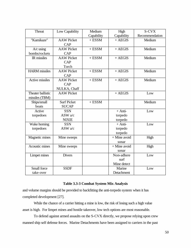
50
Threat Low Capability Medium Capability
High Capability
S-CVX Recommendation
"Kamikaze" AAW Picket CAP
+ ESSM + AEGIS Medium
A/c using bombs/rockets
AAW Picket CAP
+ ESSM + AEGIS Medium
IR missiles AAW Picket CAP Torch
+ ESSM + AEGIS Medium
HARM missiles AAW Picket CAP
+ ESSM + AEGIS Medium
Active missiles AAW Picket CAP
NULKA, Chaff
+ ESSM + AEGIS Medium
Theater ballistic missiles (TBM)
AAW Picket + AEGIS Low
Ships/small boats
Surf Picket SUCAP
+ ESSM Medium
Active torpedoes
SSN ASW a/c NIXIE
+ Anti-torpedo torpedo
Low
Wake homing torpedoes
SSN ASW a/c
+ Anti-torpedo torpedo
Low
Magnetic mines Mine sweeps + Mine avoid sonar
High
Acoustic mines Mine sweeps + Mine avoid sonar
High
Limpet mines Divers Non-adhere surf
Mine detect
Low
Small force take-over
SSDF Marine Detachment
Low
Table 3.3-3 Combat System Mix Analysis
and volume margins should be provided to backfitting the anti-torpedo system when it has
completed development [27].
While the chance of a carrier hitting a mine is low, the risk of losing such a high value
asset is high. For limpet mines and hostile takeover, low tech options are most reasonable.
To defend against armed assaults on the S-CVX directly, we propose relying upon crew
manned ship self defense forces. Marine Detachments have been assigned to carriers in the past

51
with one of their main tasks being protection of the nuclear weapons. Now that nuclear weapons
are not regularly maintained on carriers we consider the Marine Detachment no longer warranted
and adding the detachment back just to defend against a hostile takeover is not justified.
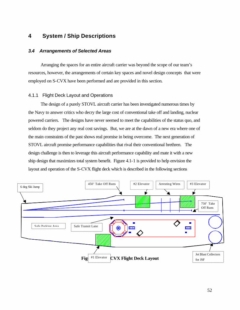
52
4 System / Ship Descriptions
3.4 Arrangements of Selected Areas
Arranging the spaces for an entire aircraft carrier was beyond the scope of our team’s
resources, however, the arrangements of certain key spaces and novel design concepts that were
employed on S-CVX have been performed and are provided in this section.
4.1.1 Flight Deck Layout and Operations
The design of a purely STOVL aircraft carrier has been investigated numerous times by
the Navy to answer critics who decry the large cost of conventional take off and landing, nuclear
powered carriers. The designs have never seemed to meet the capabilities of the status quo, and
seldom do they project any real cost savings. But, we are at the dawn of a new era where one of
the main constraints of the past shows real promise in being overcome. The next generation of
STOVL aircraft promise performance capabilities that rival their conventional brethren. The
design challenge is then to leverage this aircraft performance capability and mate it with a new
ship design that maximizes total system benefit. Figure 4.1-1 is provided to help envision the
layout and operation of the S-CVX flight deck which is described in the following sections
Figure 4.1-1 S-CVX Flight Deck Layout
Safe Parking Area
6 deg Ski Jump450’ Take Off Runs #2 Elevator Arresting Wires #3 Elevator
750’ Take Off Runs
#1 Elevator Jet Blast Collectors
for JSF
Safe Transit Lane

53
4.1.1.1 Aircraft Recovery
Conventional arrested recovery requires maintaining a large landing area and the
associated aircraft parking safe zones that consume a big piece of flight deck real estate. It is also
a series process; only one aircraft can land at a time and the arresting gear must be realigned after
each landing. This limits the recovery rate and slows sortie generation. Vertical recovery of
aircraft frees the carrier from this limitation. With two dedicated JSF landing zones, recovery
rate is at least doubled from that of a conventional take off and landing (CTOL) carrier and can
realistically go higher. One of the major concerns with using STOVL aircraft, however, is the
heat, blast and noise generated by the engine when in vertical mode. To overcome the heat and
blast effects in hover, our design incorporates a Jet Blast Collector (JBC) at each JSF recovery
circle on the aft end of the flight deck. The JBC (see figure 4.1-2) is an 18 meter diameter
circular grid structure that allows the jet blast to flow through to a collector box below deck
where it redirects the jet blast overboard. Due to the high temperature of the exhaust gas
(≈1000 °C), the grid and collector will have to be actively cooled, just as the Jet Blast Deflectors
are actively cooled on existing carriers. Once on deck, the aircraft transit under their own power
to outside the Pit Stop or queue up to along the port side to await their turn for servicing.
Figure 4.1-2 S-CVX Jet Blast Deflector
Flight Deck
Edge Transom
Jet Blast In
Flow Through
Grid
Actively Cooled Box and Grid
Exhaust Directed
Overboard
Plan View
Side View

54
4.1.1.2 Pit Stops
The process of arming and fueling current aircraft is manpower intensive and time
consuming due to the requirement to move the aircraft and/or equipment to different locations on
the flight deck for each evolution. This safety derived requirement is designed to separate these
potentially risk filled operations on an exposed flight deck. Our design rethinks this entire
process by centralizing all tactical aircraft servicing evolutions into four enclosed pits contained
within the island structure. Arming, refueling, flight line repairs, and pilot change outs for the
JSF can all be accomplished in one stop, eliminating additional aircraft movements. Enclosing
the pits within the island provides weather, acoustic, weapons fragment and CBR protection.
• Arming: Aircraft will enter the pits from the port side of the flight deck through the armored
articulating doors. Once positioned inside, the door is closed and the aircraft will be
automatically armed by the weapons handling robots that load the weapons from the
weapons gallery below. Weapons bays and external hard points on the JSF are equally
accessible to the robots and are loaded as required. De-arming of the aircraft is accomplished
by reversing the process.
• Fueling: The aircraft will be fueled automatically via the in-flight refueling probe using an
overhead gantry robot. The aircraft can be fueled in 7.5 minutes using existing 200 gpm fuel
pumps or in five minutes by reasonably increasing pump capacity to 300 gpm.
• Flight Line Repairs: Diagnostics and maintenance can be performed out of the weather by
squadron personnel.
• Pilot Change Outs: Projected aircraft availability rates for the JSF indicate that pilot
endurance will become the limiting factor in sustained operations, so 2.5 aircrews will be
provided per aircraft. The pilot swap can be accomplished in the protected pit environment.
• Aircraft Washing: Corrosion control of the aircraft demands manpower intensive hand
washing of the aircraft on a regular basis. The aft pit therefore will be equipped with an
automated aircraft washing system that will accommodate all the aircraft types.
4.1.1.3 Launching
Once the aircraft is serviced, it departs the pit through the starboard side door and
proceeds directly to the take off area using the aircraft transit safe lane on the starboard side of
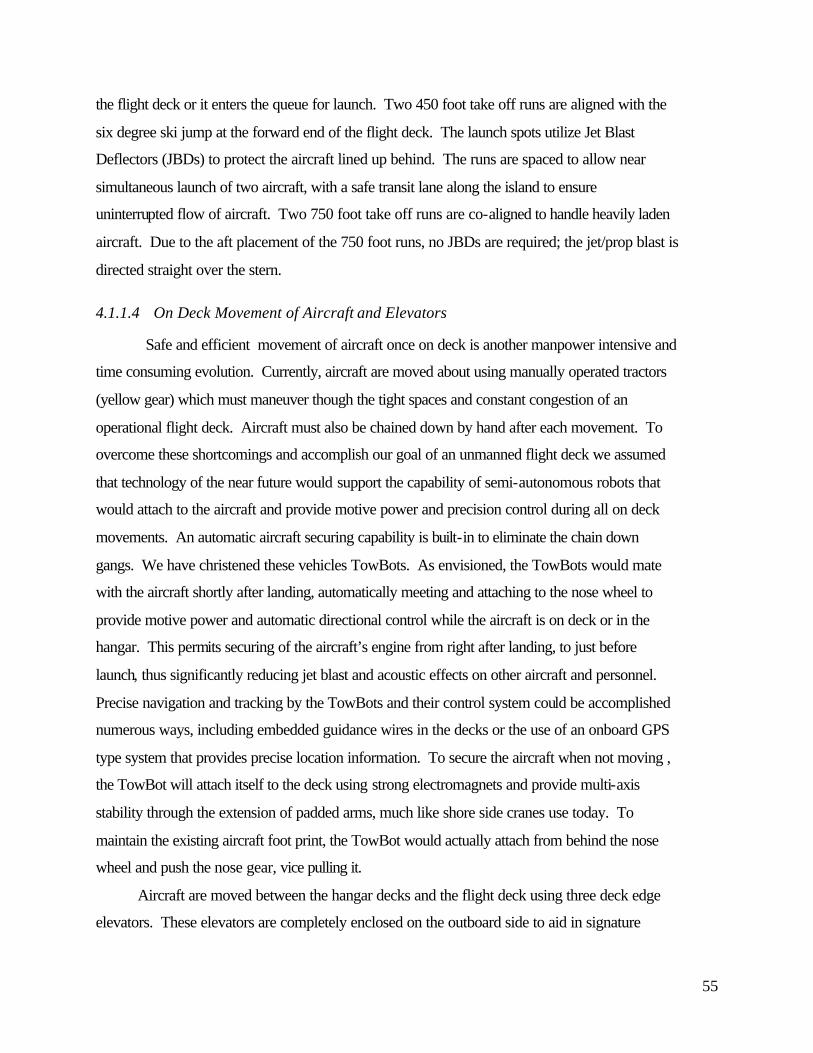
55
the flight deck or it enters the queue for launch. Two 450 foot take off runs are aligned with the
six degree ski jump at the forward end of the flight deck. The launch spots utilize Jet Blast
Deflectors (JBDs) to protect the aircraft lined up behind. The runs are spaced to allow near
simultaneous launch of two aircraft, with a safe transit lane along the island to ensure
uninterrupted flow of aircraft. Two 750 foot take off runs are co-aligned to handle heavily laden
aircraft. Due to the aft placement of the 750 foot runs, no JBDs are required; the jet/prop blast is
directed straight over the stern.
4.1.1.4 On Deck Movement of Aircraft and Elevators
Safe and efficient movement of aircraft once on deck is another manpower intensive and
time consuming evolution. Currently, aircraft are moved about using manually operated tractors
(yellow gear) which must maneuver though the tight spaces and constant congestion of an
operational flight deck. Aircraft must also be chained down by hand after each movement. To
overcome these shortcomings and accomplish our goal of an unmanned flight deck we assumed
that technology of the near future would support the capability of semi-autonomous robots that
would attach to the aircraft and provide motive power and precision control during all on deck
movements. An automatic aircraft securing capability is built-in to eliminate the chain down
gangs. We have christened these vehicles TowBots. As envisioned, the TowBots would mate
with the aircraft shortly after landing, automatically meeting and attaching to the nose wheel to
provide motive power and automatic directional control while the aircraft is on deck or in the
hangar. This permits securing of the aircraft’s engine from right after landing, to just before
launch, thus significantly reducing jet blast and acoustic effects on other aircraft and personnel.
Precise navigation and tracking by the TowBots and their control system could be accomplished
numerous ways, including embedded guidance wires in the decks or the use of an onboard GPS
type system that provides precise location information. To secure the aircraft when not moving ,
the TowBot will attach itself to the deck using strong electromagnets and provide multi-axis
stability through the extension of padded arms, much like shore side cranes use today. To
maintain the existing aircraft foot print, the TowBot would actually attach from behind the nose
wheel and push the nose gear, vice pulling it.
Aircraft are moved between the hangar decks and the flight deck using three deck edge
elevators. These elevators are completely enclosed on the outboard side to aid in signature
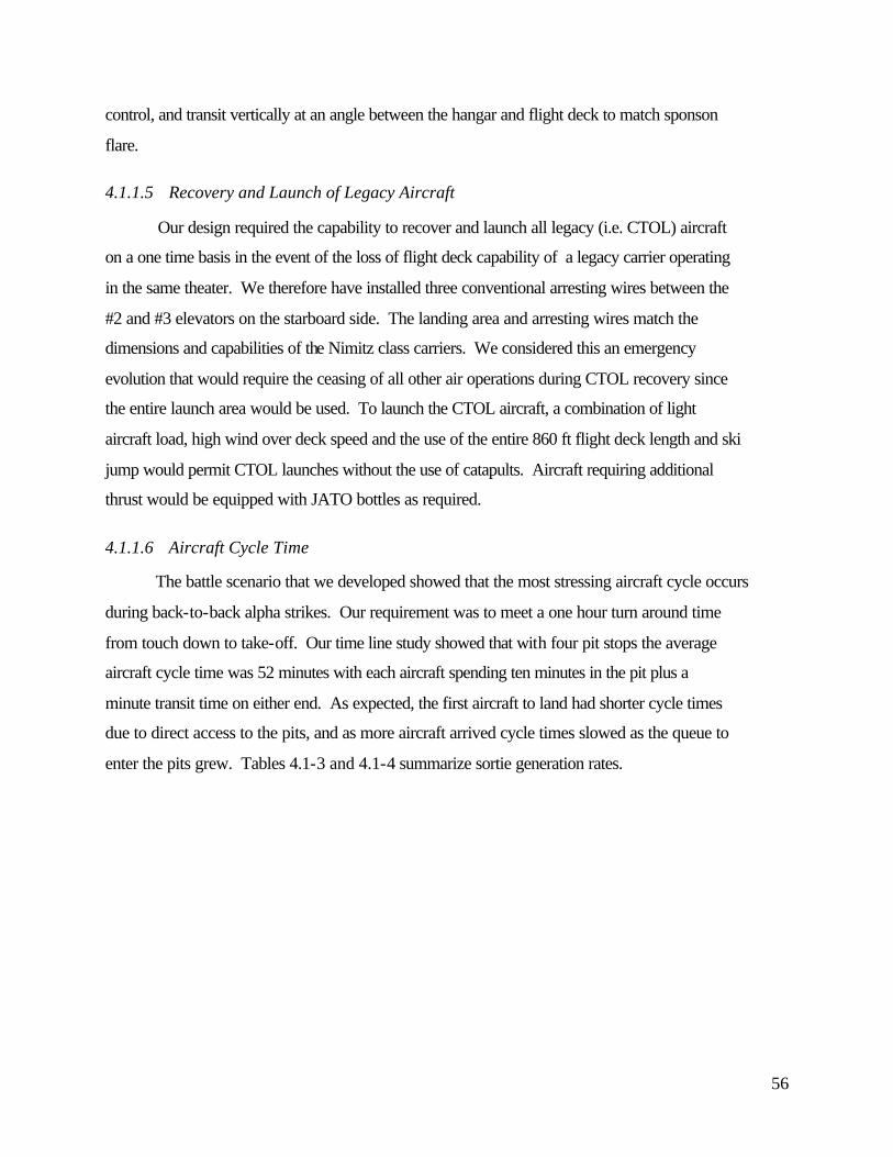
56
control, and transit vertically at an angle between the hangar and flight deck to match sponson
flare.
4.1.1.5 Recovery and Launch of Legacy Aircraft
Our design required the capability to recover and launch all legacy (i.e. CTOL) aircraft
on a one time basis in the event of the loss of flight deck capability of a legacy carrier operating
in the same theater. We therefore have installed three conventional arresting wires between the
#2 and #3 elevators on the starboard side. The landing area and arresting wires match the
dimensions and capabilities of the Nimitz class carriers. We considered this an emergency
evolution that would require the ceasing of all other air operations during CTOL recovery since
the entire launch area would be used. To launch the CTOL aircraft, a combination of light
aircraft load, high wind over deck speed and the use of the entire 860 ft flight deck length and ski
jump would permit CTOL launches without the use of catapults. Aircraft requiring additional
thrust would be equipped with JATO bottles as required.
4.1.1.6 Aircraft Cycle Time
The battle scenario that we developed showed that the most stressing aircraft cycle occurs
during back-to-back alpha strikes. Our requirement was to meet a one hour turn around time
from touch down to take-off. Our time line study showed that with four pit stops the average
aircraft cycle time was 52 minutes with each aircraft spending ten minutes in the pit plus a
minute transit time on either end. As expected, the first aircraft to land had shorter cycle times
due to direct access to the pits, and as more aircraft arrived cycle times slowed as the queue to
enter the pits grew. Tables 4.1-3 and 4.1-4 summarize sortie generation rates.
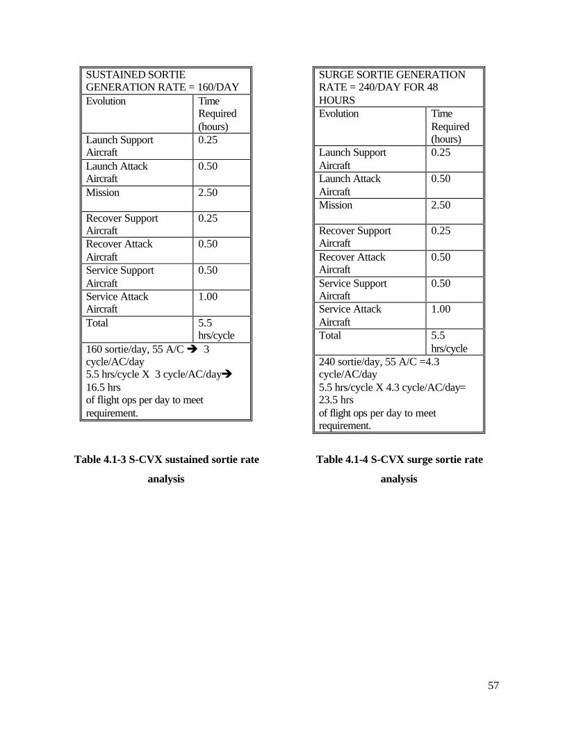
57
SUSTAINED SORTIE GENERATION RATE = 160/DAY Evolution Time
Required (hours)
Launch Support Aircraft
0.25
Launch Attack Aircraft
0.50
Mission 2.50
Recover Support Aircraft
0.25
Recover Attack Aircraft
0.50
Service Support Aircraft
0.50
Service Attack Aircraft
1.00
Total 5.5 hrs/cycle
160 sortie/day, 55 A/C è 3 cycle/AC/day 5.5 hrs/cycle X 3 cycle/AC/dayè 16.5 hrs of flight ops per day to meet requirement.
Table 4.1-3 S-CVX sustained sortie rate
analysis
SURGE SORTIE GENERATION RATE = 240/DAY FOR 48 HOURS Evolution Time
Required (hours)
Launch Support Aircraft
0.25
Launch Attack Aircraft
0.50
Mission 2.50
Recover Support Aircraft
0.25
Recover Attack Aircraft
0.50
Service Support Aircraft
0.50
Service Attack Aircraft
1.00
Total 5.5 hrs/cycle
240 sortie/day, 55 A/C =4.3 cycle/AC/day 5.5 hrs/cycle X 4.3 cycle/AC/day= 23.5 hrs of flight ops per day to meet requirement.
Table 4.1-4 S-CVX surge sortie rate
analysis

58
4.1.2 Hangar Deck Layout
The S-CVX hangar is divided into two main sections, the forward and after hangar bays
which can be separated by an articulating fire door. The forward hangar bay also contains a
smaller section which we label the forward aircraft repair facility. In normal operations, aircraft
requiring more in-depth maintenance would be positioned here because it imposes the least effect
on movement in other areas of the hangar. During humanitarian and operations other than war
support missions, however, this area is given up for other uses as explained in the next section.
Figure 4.1-5 shows the layout of the S-CVX hangars and Table 4.1-6 describes their salient
features.
Figure 4.1-5 S-CVX Hangar Deck Layout
Elevator #3 Elevator #2
Elevator #1
Forward A/C
Repair Bay
Hangar Bay
Segregation Door
Hangar Bay #1 Hangar Bay #2 Forward
Avionics Repair Shops
Engine Repair
Composites Repair
Machine Shops
Engine Test Cell
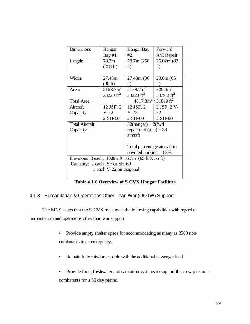
59
Dimensions Hangar Bay #1
Hangar Bay #2
Forward A/C Repair
Length: 78.7m (258 ft)
78.7m (258 ft)
25.02m (82 ft)
Width: 27.43m (90 ft)
27.43m (90 ft)
20.0m (65 ft)
Area: 2158.7m2 23220 ft2
2158.7m2 23220 ft2
500.4m2 5379.2 ft2
Total Area 4817.8m2 / 51819 ft2 Aircraft Capacity
12 JSF, 2 V-22 2 SH-60
12 JSF, 2 V-22 2 SH-60
2 JSF, 2 V-22 5 SH-60
Total Aircraft Capacity:
32(hangar) + 2(fwd repair)+ 4 (pits) = 38 aircraft Total percentage aircraft in covered parking = 63%
Elevators: 3 each, 19.8m X 16.7m (65 ft X 55 ft) Capacity: 2 each JSF or SH-60 1 each V-22 on diagonal
Table 4.1-6 Overview of S-CVX Hangar Facilities
4.1.3 Humanitarian & Operations Other Than War (OOTW) Support
The MNS states that the S-CVX must meet the following capabilities with regard to
humanitarian and operations other than war support:
• Provide empty shelter space for accommodating as many as 2500 non-
combatants in an emergency.
• Remain fully mission capable with the additional passenger load.
• Provide food, freshwater and sanitation systems to support the crew plus non-
combatants for a 30 day period.
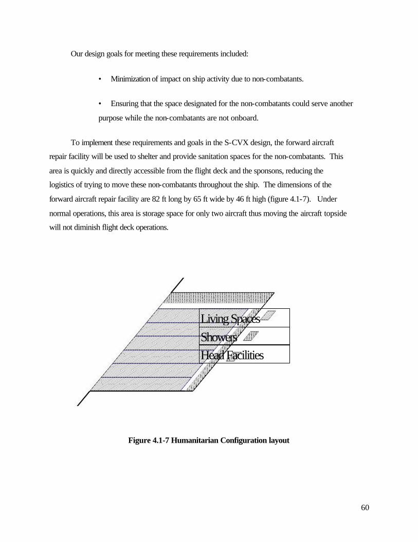
60
Our design goals for meeting these requirements included:
• Minimization of impact on ship activity due to non-combatants.
• Ensuring that the space designated for the non-combatants could serve another
purpose while the non-combatants are not onboard.
To implement these requirements and goals in the S-CVX design, the forward aircraft
repair facility will be used to shelter and provide sanitation spaces for the non-combatants. This
area is quickly and directly accessible from the flight deck and the sponsons, reducing the
logistics of trying to move these non-combatants throughout the ship. The dimensions of the
forward aircraft repair facility are 82 ft long by 65 ft wide by 46 ft high (figure 4.1-7). Under
normal operations, this area is storage space for only two aircraft thus moving the aircraft topside
will not diminish flight deck operations.
Living SpacesShowersHead Facilities
Figure 4.1-7 Humanitarian Configuration layout
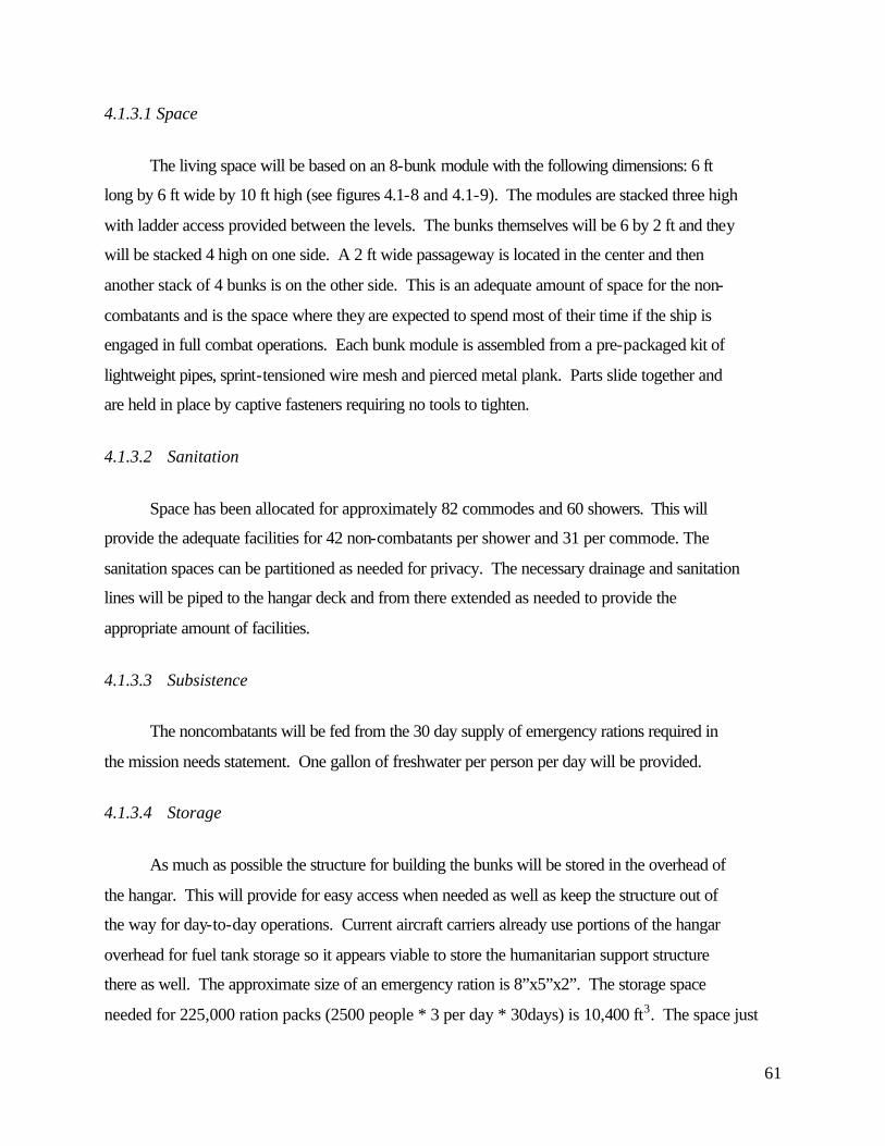
61
4.1.3.1 Space
The living space will be based on an 8-bunk module with the following dimensions: 6 ft
long by 6 ft wide by 10 ft high (see figures 4.1-8 and 4.1-9). The modules are stacked three high
with ladder access provided between the levels. The bunks themselves will be 6 by 2 ft and they
will be stacked 4 high on one side. A 2 ft wide passageway is located in the center and then
another stack of 4 bunks is on the other side. This is an adequate amount of space for the non-
combatants and is the space where they are expected to spend most of their time if the ship is
engaged in full combat operations. Each bunk module is assembled from a pre-packaged kit of
lightweight pipes, sprint-tensioned wire mesh and pierced metal plank. Parts slide together and
are held in place by captive fasteners requiring no tools to tighten.
4.1.3.2 Sanitation
Space has been allocated for approximately 82 commodes and 60 showers. This will
provide the adequate facilities for 42 non-combatants per shower and 31 per commode. The
sanitation spaces can be partitioned as needed for privacy. The necessary drainage and sanitation
lines will be piped to the hangar deck and from there extended as needed to provide the
appropriate amount of facilities.
4.1.3.3 Subsistence
The noncombatants will be fed from the 30 day supply of emergency rations required in
the mission needs statement. One gallon of freshwater per person per day will be provided.
4.1.3.4 Storage
As much as possible the structure for building the bunks will be stored in the overhead of
the hangar. This will provide for easy access when needed as well as keep the structure out of
the way for day-to-day operations. Current aircraft carriers already use portions of the hangar
overhead for fuel tank storage so it appears viable to store the humanitarian support structure
there as well. The approximate size of an emergency ration is 8”x5”x2”. The storage space
needed for 225,000 ration packs (2500 people * 3 per day * 30days) is 10,400 ft3. The space just
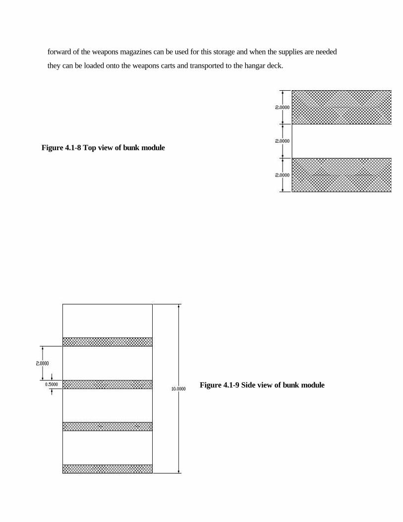
62
forward of the weapons magazines can be used for this storage and when the supplies are needed
they can be loaded onto the weapons carts and transported to the hangar deck.
Figure 4.1-8 Top view of bunk module
Figure 4.1-9 Side view of bunk module
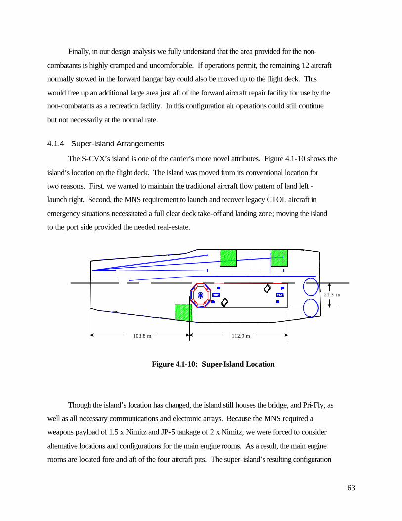
63
Finally, in our design analysis we fully understand that the area provided for the non-
combatants is highly cramped and uncomfortable. If operations permit, the remaining 12 aircraft
normally stowed in the forward hangar bay could also be moved up to the flight deck. This
would free up an additional large area just aft of the forward aircraft repair facility for use by the
non-combatants as a recreation facility. In this configuration air operations could still continue
but not necessarily at the normal rate.
4.1.4 Super-Island Arrangements
The S-CVX’s island is one of the carrier’s more novel attributes. Figure 4.1-10 shows the
island’s location on the flight deck. The island was moved from its conventional location for
two reasons. First, we wanted to maintain the traditional aircraft flow pattern of land left -
launch right. Second, the MNS requirement to launch and recover legacy CTOL aircraft in
emergency situations necessitated a full clear deck take-off and landing zone; moving the island
to the port side provided the needed real-estate.
112.9 m
21.3 m
103.8 m
Figure 4.1-10: Super-Island Location
Though the island’s location has changed, the island still houses the bridge, and Pri-Fly, as
well as all necessary communications and electronic arrays. Because the MNS required a
weapons payload of 1.5 x Nimitz and JP-5 tankage of 2 x Nimitz, we were forced to consider
alternative locations and configurations for the main engine rooms. As a result, the main engine
rooms are located fore and aft of the four aircraft pits. The super-island’s resulting configuration
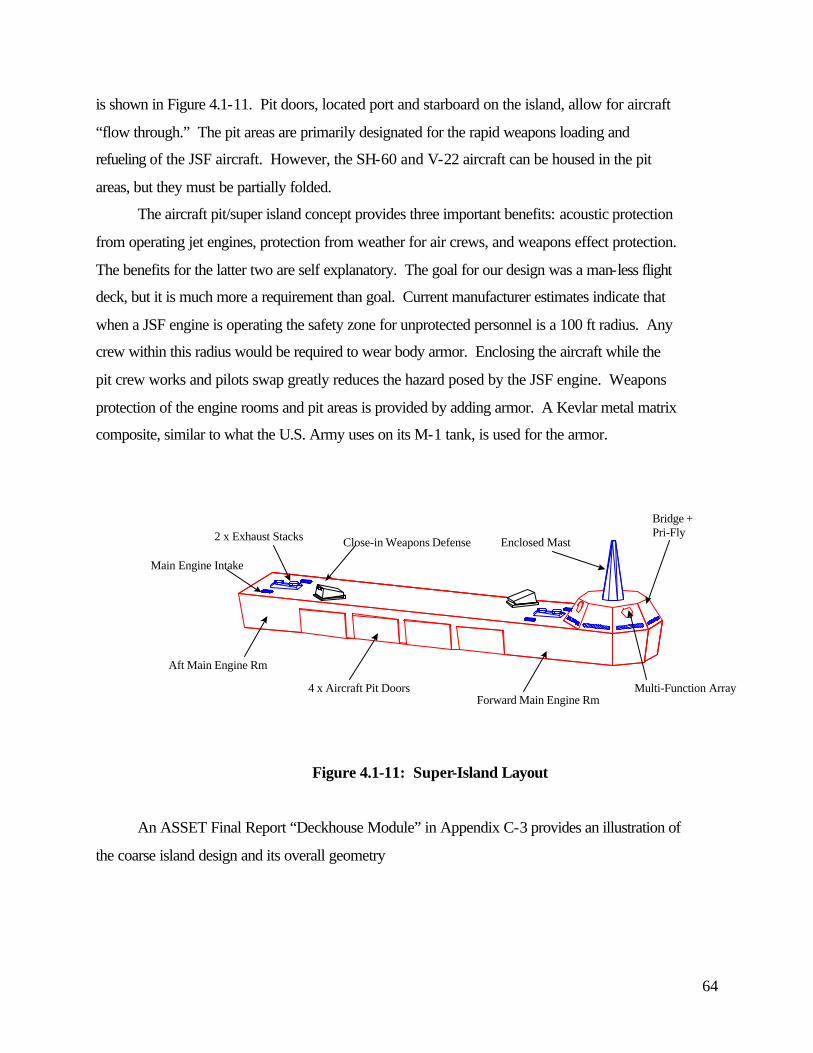
64
is shown in Figure 4.1-11. Pit doors, located port and starboard on the island, allow for aircraft
“flow through.” The pit areas are primarily designated for the rapid weapons loading and
refueling of the JSF aircraft. However, the SH-60 and V-22 aircraft can be housed in the pit
areas, but they must be partially folded.
The aircraft pit/super island concept provides three important benefits: acoustic protection
from operating jet engines, protection from weather for air crews, and weapons effect protection.
The benefits for the latter two are self explanatory. The goal for our design was a man-less flight
deck, but it is much more a requirement than goal. Current manufacturer estimates indicate that
when a JSF engine is operating the safety zone for unprotected personnel is a 100 ft radius. Any
crew within this radius would be required to wear body armor. Enclosing the aircraft while the
pit crew works and pilots swap greatly reduces the hazard posed by the JSF engine. Weapons
protection of the engine rooms and pit areas is provided by adding armor. A Kevlar metal matrix
composite, similar to what the U.S. Army uses on its M-1 tank, is used for the armor.
Multi-Function Array
Main Engine Intake
Close-in Weapons Defense2 x Exhaust Stacks
4 x Aircraft Pit Doors
Enclosed Mast
Bridge + Pri-Fly
Forward Main Engine Rm
Aft Main Engine Rm
Figure 4.1-11: Super-Island Layout
An ASSET Final Report “Deckhouse Module” in Appendix C-3 provides an illustration of
the coarse island design and its overall geometry
65
4.1.5 Bridge and Primary Flight Control and Engineering Operating Station (EOS)
Arrangements
The large pilot house at the forward end of the super island houses (among other
functions) the ship’s bridge and the primary flight control or Pri-Fly station. These two functions
have intentionally been arranged in close proximity to each other to allow for better overall
coordination between the OOD, the Air Boss and the ship’s command element (CO/XO) with
regard to ship and air wing operations. The design goals of the bridge and the Pri-Fly station
layouts were:
• Minimized manning
• Integration of functions ( e.g. consolidation of the main Engineering Operation
Station (EOS), navigation center and ship control functions into a single location)
• Improved functionality
• Enhanced survivability
The decision to locate the bridge topside resulted from an in depth look at survivability vs.
functionality. Traditionally, the bridge and Pri-Fly are both located topside to provide
watchstanders the ability to see what is going on. The degree of automation used aboard the S-
CVX would allow locating the bridge and Pri-Fly below decks, which would have greatly
enhanced the survivability of that space. The super-island is an especially vulnerable place due
to the infrared signatures of the engines. A compromise was reached by locating the bridge and
Pri-Fly topside but providing redundant capabilities in CVIC (which is located below the
waterline) in case of a loss of the primary space.
The bridge and Pri-Fly are located in the forward-most part of the super-island. The space
is divided into two areas by an athwartships bulkhead, Pri-Fly is in the aft part and the bridge is
forward. Windows completely surround the space which allows the Officer of the Deck (OOD) to
move to the Pri-Fly portion of the space to complete a 360 degree view of the horizon while still
protected by the skin of the ship.
The bridge integrates both navigation control and engineering control ship functions.
Conceptually, there will be an experienced junior officer as the OOD and two less-experienced
junior officers assigned as Junior Officer of the Deck (JOOD) and the Engineering Officer of the
Watch (EOOW). The JOOD will be the OOD’s assistant in matters pertaining to navigation and
shipping and the EOOW will be the engineering assistant. There will be three consoles
66
dedicated to the engineering functions on the bridge and a flat screen navigation table used for
charts.
In order to reduce the manning needed to perform the routine tasks on the bridge, S-CVX
incorporates the latest computers and technology. The Sperry Marine integrated control system
is an example of the type of system which would be needed to support these minimally manned
watch stations.
The Sperry Marine system incorporates the following different types of console
configurations (each system is Microsoft Windows NT based):
• Voyage Management System (VMS)
• Integrated Condition Assessment System (ICAS)
• Damage Control System (DCS)
• Standard Monitoring Control System (SMCS)
The Voyage Management System provides all voyage planning, electronic charts, as well
as autopilot capabilities. It can also handle weather displays and log-keeping functions.
ICAS is a diagnostic tool used to monitor machinery and provides information about the
equipment such as symptom analysis, online documentation, failure trends and supply support.
It will also schedule and document maintenance, provide online training, and handle all
engineering log-keeping needs.
The Damage Control System incorporates the ship’s drawings to make damage control
plotting easier. It also can allow wireless connectivity with damage control teams and can be
integrated with the Main Space Fire Doctrine to recommend prioritized corrective actions.
SMCS allows integrated, remote control of the engineering plant.
Pri-Fly will incorporate the following aircraft control functions which were previously
handled in separate spaces on traditional carriers:
• Fly One
• Fly Two
• Fly Three
• Flight Deck Control
• Aircraft communications
Pri-Fly consists of standard consoles used throughout the rest of the ship with special
software installed to allow them to be also used for aircraft control. In particular, the flight deck

67
control function will be handled by a flat screen display table which will be able to show the
hangar and flight deck layouts with current aircraft locations.
4.1.6 Engineering Operating Station (EOS) Layout
Complete control of S-CVX’s IPS and main engines is conducted at the engineering
operating station. There are four EOS stations within the ship: 1 - Bridge; 2 - Forward Engine
Room; 3 - Aft Engine Room; and 4 - Emergency Engine Room. Figure 4.1-13 shows the general
locations.
Forward Engine Rm2 x LM-6000 +& 1 x EOS Station
Flight Deck FireFightingEquipment
Aft Engine Rm2 x LM-6000 +& 1 x EOS Station
Emergency Engine Rm2 x CAT 3616 mod +& 1 EOS Station
EOS ≡ 1 SMCS, 1 DCS, 1 ICAS
Bridge EOS
Aux Machine Rm1 x “Slave” EOS
Figure 4.1-12: Engineering Operation Station Locations
An EOS consists of three consoles: one Standard Monitor and Control System (SMCS),
one Damage Control System (DCS), and one Integrated Condition Assessment System (ICAS).
The multifunction SMCS which controls all the engineering operations is connected to the
computer and communications system’s ship-wide or backbone network. By linking the SMCS
to the network the engineering officer watch can be performed in any of the locations shown.
The DCS and ICAS stations are used to monitor damage control and equipment condition,
respectively. ICAS is used to help replace traditional maintenance practices; equipment
conditions and operating parameters are monitored and recorded. When an operating parameter,
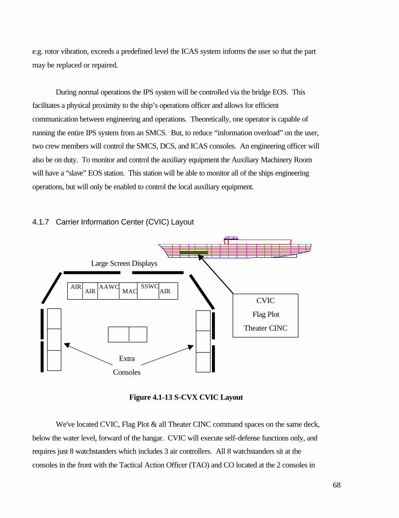
68
e.g. rotor vibration, exceeds a predefined level the ICAS system informs the user so that the part
may be replaced or repaired.
During normal operations the IPS system will be controlled via the bridge EOS. This
facilitates a physical proximity to the ship’s operations officer and allows for efficient
communication between engineering and operations. Theoretically, one operator is capable of
running the entire IPS system from an SMCS. But, to reduce “information overload” on the user,
two crew members will control the SMCS, DCS, and ICAS consoles. An engineering officer will
also be on duty. To monitor and control the auxiliary equipment the Auxiliary Machinery Room
will have a “slave” EOS station. This station will be able to monitor all of the ships engineering
operations, but will only be enabled to control the local auxiliary equipment.
4.1.7 Carrier Information Center (CVIC) Layout
Figure 4.1-13 S-CVX CVIC Layout
We've located CVIC, Flag Plot & all Theater CINC command spaces on the same deck,
below the water level, forward of the hangar. CVIC will execute self-defense functions only, and
requires just 8 watchstanders which includes 3 air controllers. All 8 watchstanders sit at the
consoles in the front with the Tactical Action Officer (TAO) and CO located at the 2 consoles in
AIR AIR
AAWC SSWC AIR
Extra
Consoles
Large Screen Displays
MAC
CVIC
Flag Plot
Theater CINC
69
the center. The main personnel reduction concerns the Multi-Functional Arrays. We see the
current Radar, EW, Link, and ID Supervisors combined into just 1 watch station. Six extra
consoles are provided for Force Coordinators & extra air controllers. Also, if Flag Plot or the
Pilot House are destroyed, those functions can move to CVIC with no loss in warfighting
capability.
4.2 Hull Design
The S-CVX hull was developed using the Naval Sea Systems Command’s computer
program Advanced Surface Ship Evaluation Tool - ASSET, MONOCV version 4.1.0. A
complete set of ASSET generated reports is provided as Appendix C-3. Hull plan, profile, and
end views are shown in Figure 4.2-1.

70
Figure 4.2-1: S-SCVX Hull plan, profile, and end views
Stern LBP = 250 m
LOA= 259
73
.2
40 m
Bow

71
4.2.2 Signature Reduction Efforts
The MNS levied a requirement that S-CVX maintain the same ship’s signatures as the
much smaller Spruance-class destroyers. A great deal of effort was devoted during the course of
our design to meet this challenge. The goal of these reductions was not to make the carrier
invisible, but rather to make it indistinguishable from other Battle Group assets.
4.2.1.1 Radar Cross Section (RCS)
The RCS problem actually had two dimensions. The MNS states that the S-CVX had to
present minimal signatures against both sea skimming and high altitude cruise missiles at a range
of 50 km or greater. Since no RCS prediction codes were available for student use, a very
simplified geometric analysis was the best that could be done. Our approach was to model S-
CVX against both missile profiles using a spreadsheet, and then manipulate the shape until
achieving RCS and functionality goals. For comparison data for the DD, we were limited to a
1990 NRL study (title classified) that used an I-band radar of 9.7 GHz. We also had to make a
number of assumptions:
1.) The ship’s surface is smooth & specular, and can represented by rectangles.
2.) There are no aircraft on the flight deck.
3.) All elevators to the hangar deck are enclosed (a missile can not look directly
into the hangar.
4.) Missile seeker is beam on.
Also, a similar hull geometry to that of a Nimitz class carrier is used for S-CVX. The hull
is assumed to make a 50 degree angle with the waterline for 2/3 of its length and a 80 degree
angle for the remaining 1/3.
To prevent a high flying (100K ft) cruise missile from seeing a normal reflected surface as it
closes to a range of 50 km, we either had to design the super island and pilot house with a greater
than 30 degree tumblehome or a flare of any angle. Since available hangar space was limited
within the super island, we went the maximum allowable flare: 9 degrees. A 30 degree
tumblehome was acceptable for the pilot house (plenty of room to spare).
72
By incorporating the described geometry into the S-CVX’s design, we reduced our RCS
to a couple orders of magnitude below a Spruance for the sea skimmer case. This is not terribly
surprising given the Spruance’s box-like design. S-CVX is roughly the same order of magnitude
however for the high flyer. This is because the S-CVX’s large flight deck now becomes a factor
in the RCS equation. Given the simplicity of our model, the goal has been achieved. However,
as higher order effects are considered, such as adding appendages and aircraft on the flight deck,
our numbers will most certainly rise.
4.2.1.2 Infrared Signatures
In order to meet our infrared signature goals, the S-CVX needed a contrast signature no
larger than a Spruance class destroyer in both the 3-5 and 8-12 um bands. In performing our
analysis, we were limited to a 1982 MIT study (title again classified) that recorded a background
temperature of 55F. This is colder than normal, and it hurt our analysis. We also made two
assumptions:
1.) Hull temperature is 70F for all spaces except engine rooms.
2.) Exterior engine room temperature is 100F.
With these assumptions in mind, our results show that in the 3-5 um band the S-CVX IR
signature is less than a kW/str (kilowatt per steradian) above a Spruance. Given the destroyer’s
signature in order of magnitude, this is not tactically significant.
In the 8-12 um band, though, our problem was worse. S-CVX has a hull 4 times the size
of a destroyer’s. The problem is that this larger hull is (on average) 15F above the ambient
temperature of 55F used in the MIT study. So even without examining specific hot spots, the S-
CVX presents a much larger contrast signature than the DD. However, as the ambient
temperature rises, the S-CVX’s contrast signature decreases faster than the DD’s. The gap in
signatures therefore shrinks. Unfortunately, further IR signature reductions required more than
we were able to afford as part of this report. In future design iterations, however, we would
recommend exploring the use of an active cooling system. This is where sea water is sent
throughout the skin of the ship thereby cooling the exterior surface below 70o F.
4.2.1.3 Acoustic Signature
Getting a grip on this signature area is quite difficult. Ship data is mostly empirical, and
there is no baseline available for a combatant using propulsive pods. Noise from shafting should
73
be almost completely eliminated using this scheme but the data is not there to confirm this
hypothesis. Finally, while advances in propeller design may provide some reduction in
cavitation noise, this will remain as the weak point in signature reduction.
4.2.2 Passive Protection Systems
With the changing world politics has come ever expanding roles for the carrier battle
group. Littoral operations and the associated higher risks that they pose, are likely operating
environments for the next generation carrier. Thus protection from underwater weapons and
surface missiles was a considerable concern. Several measures were incorporated into S-CVX’s
design to enhance its survivability.
Topside the super island engine rooms and aircraft pits are fully armored with a Kevlar
metal matrix composite, similar to what the U.S. Army uses on its M-1 tank. This armor will
likely not stop a direct hit, but it will prevent fragments and inhibit cascading damages. Below
the flight deck all vital compartments are shielded by a double hull or multiple bulkheads (for
interior sections). Those compartments considered vital include: the hangar, auxiliary machinery
room, weapons magazines, and the emergency engine room. The lowest deck on the ship is
protected from the bottom via an inner bottom.
4.2.3 Magazine Design
The MNS for S-CVX required a weapons magazine of one and half times that of the Nimitz
class. This requirement proved most challenging to our design team. Ultimately, housing all the
weapons was one of the driving reasons for removing the engine rooms from the hull of the ship
and locating them within the super island. The total magazine volume was over 30,000 m3; this
is approximately 15% of the total hull volume. The weapons handling system elevators and rail
system are not accounted for in this figure. A special note must be made regarding the allocation
of magazine volume within the ship. ASSET will not allow the user to locate the engine room
volume above the first deck. Though ASSET placed the two main machinery rooms within the
hull, the complete volume of these engine rooms was added to the weapons magazine volume,
making workarounds necessary. The compartment breakdown for magazine location is listed in
“Hull Subdivision Module” of Appendix C-3.
74
4.2.4 Tankage Design
ASSET automatically allocates tank volume for ship’s own fuel once the main engines and
endurance speed are input into the program. But, tank volume for aircraft fuel must be allocated
by the user. Most of the space between the double hull compartments is allocated as tankage for
JP-5. This is a recognized potential hazard; however, this tank location is standard practice;
most Navy ships store their fuel in compartments adjacent to the outer hull.
4.3 Ordnance Handling System
The methods of storage, assembly, transportation and mating of aviation ordnance to
aircraft on board the current Nimitz class aircraft carriers demands large numbers of personnel,
a large amount of deck space and can become the limiting factor in sortie rate generation. The
next generation of aircraft carrier is going to have to dramatically improve this process in order
to meet the manning and mission requirements.
The existing method has the weapons manually removed from the magazines, loaded on
skids and moved to the assembly areas below-deck using the lower stage weapons elevators. In
the assembly areas, the weapons have aerodynamic surfaces and targeting systems installed
(fuses and arming wires are installed on the flight deck) and then are staged in the assembly area
or on the hangar deck. Due to the amount of time it takes to move the large number of weapons
skids from the assembly areas to the flight deck, some weapons may be stowed outboard of the
island on the flight deck in what is called a “bomb farm”. Loading of the aircraft is done
manually and with the aid of bomb hoists. This system requires 300 personnel to operate (200 in
weapon assembly alone), limits the use of the aircraft elevators during surge operations and
crowds the flight deck with dangerous amounts of explosives.
The S-CVX must take a systems approach to improving this mission essential function.
The aircraft, the ship, the weapons and the personnel must work together seamlessly to overcome
the shortcomings of the existing system. Utilizing Just-In-Time Delivery techniques,
redesigning weapons flow paths, and leveraging robotics and automation technologies, the goal
is to reduce manning by 50 percent and reduce aircraft turn-around time to less than one hour
while maintaining or improving the existing levels of safety.
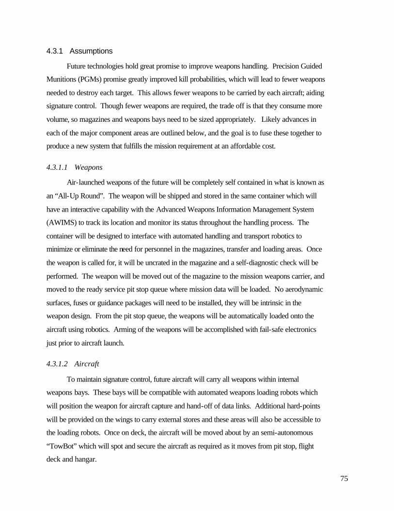
75
4.3.1 Assumptions
Future technologies hold great promise to improve weapons handling. Precision Guided
Munitions (PGMs) promise greatly improved kill probabilities, which will lead to fewer weapons
needed to destroy each target. This allows fewer weapons to be carried by each aircraft; aiding
signature control. Though fewer weapons are required, the trade off is that they consume more
volume, so magazines and weapons bays need to be sized appropriately. Likely advances in
each of the major component areas are outlined below, and the goal is to fuse these together to
produce a new system that fulfills the mission requirement at an affordable cost.
4.3.1.1 Weapons
Air-launched weapons of the future will be completely self contained in what is known as
an “All-Up Round”. The weapon will be shipped and stored in the same container which will
have an interactive capability with the Advanced Weapons Information Management System
(AWIMS) to track its location and monitor its status throughout the handling process. The
container will be designed to interface with automated handling and transport robotics to
minimize or eliminate the need for personnel in the magazines, transfer and loading areas. Once
the weapon is called for, it will be uncrated in the magazine and a self-diagnostic check will be
performed. The weapon will be moved out of the magazine to the mission weapons carrier, and
moved to the ready service pit stop queue where mission data will be loaded. No aerodynamic
surfaces, fuses or guidance packages will need to be installed, they will be intrinsic in the
weapon design. From the pit stop queue, the weapons will be automatically loaded onto the
aircraft using robotics. Arming of the weapons will be accomplished with fail-safe electronics
just prior to aircraft launch.
4.3.1.2 Aircraft
To maintain signature control, future aircraft will carry all weapons within internal
weapons bays. These bays will be compatible with automated weapons loading robots which
will position the weapon for aircraft capture and hand-off of data links. Additional hard-points
will be provided on the wings to carry external stores and these areas will also be accessible to
the loading robots. Once on deck, the aircraft will be moved about by an semi-autonomous
“TowBot” which will spot and secure the aircraft as required as it moves from pit stop, flight
deck and hangar.

76
4.3.1.3 Ship
One of the largest gains in weapons handling efficiency can be realized by minimizing the
physical movement of the weapon from the magazine to the aircraft. To this end we propose a
series of design modifications to realize these gains.
• One of the baseline requirements for our design was to increase the magazine area to 1.5
times that of the current Nimitz class. Our final design has 10,300 square meters of
magazine area, 1.45 times the area of the Nimitz. The flow paths to the elevators have
been specifically designed to offset vertical alignment of the shafts from the flight deck to
the magazines to prevent direct attacking weapon penetration.
• The weapons capacity of the magazines is calculated as follows:
(4 magazines/deck) X (78 weapons slots/magazine) X (3 decks) = 936 weapons slots
Each weapons slot has the capability to store one large weapon (i.e. SLAM-ER,
AMRAAM, JSOW, JASSM), or two smaller weapons (i.e. AIM-9X, MAVERICK,
PENGUIN). The S-CVX weapons load out will be dictated by the mission need, and
with the capability to store two weapons per slot, an upper end total of 1872 weapons
could be carried.
• The future carrier will incorporate a fully automated magazine and weapons handling
system. Robots will automatically segregate and store the different types of weapons in
accordance with use and safety compatibility. Containerized weapons will be onloaded
through the side of the ship to the hangar where they will be struck down below using the
mission weapons carriers for transport to the magazine. Expended weapons containers
will be retrograded at the same time.
• The magazines will be locatedalong the centerline of the ship, directly underneath and in
line with the island. This will allow alignment of the handling and transport elevators
with the weapons gallery located directly below the island pits. This vertical integration
of the weapons handling system greatly reduces the distance weapons travel from
magazine to the aircraft. The system has also been designed so that the weapon always
faces the same direction during handling and transport.
• The magazines will be segregated longitudinally by the main subdivisions and will
occupy three decks. Due to the containerized nature of future weapons and the need to
adapt to robotic handling, the magazines are designed around a six meter by one meter
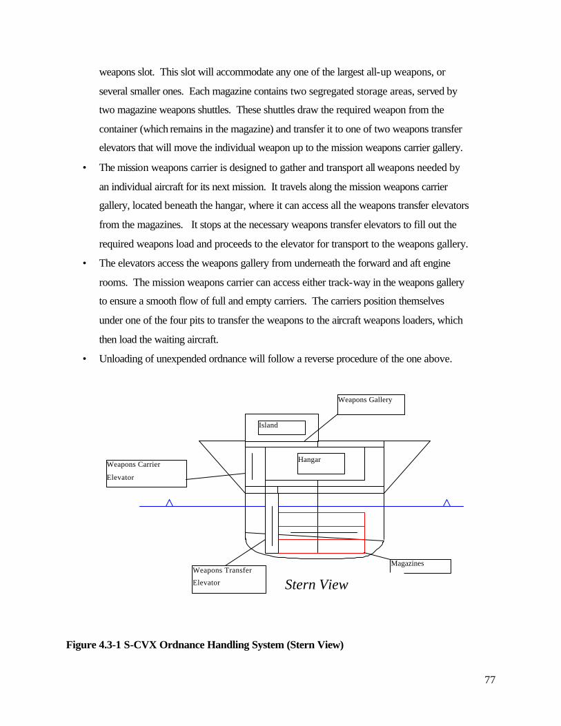
77
weapons slot. This slot will accommodate any one of the largest all-up weapons, or
several smaller ones. Each magazine contains two segregated storage areas, served by
two magazine weapons shuttles. These shuttles draw the required weapon from the
container (which remains in the magazine) and transfer it to one of two weapons transfer
elevators that will move the individual weapon up to the mission weapons carrier gallery.
• The mission weapons carrier is designed to gather and transport all weapons needed by
an individual aircraft for its next mission. It travels along the mission weapons carrier
gallery, located beneath the hangar, where it can access all the weapons transfer elevators
from the magazines. It stops at the necessary weapons transfer elevators to fill out the
required weapons load and proceeds to the elevator for transport to the weapons gallery.
• The elevators access the weapons gallery from underneath the forward and aft engine
rooms. The mission weapons carrier can access either track-way in the weapons gallery
to ensure a smooth flow of full and empty carriers. The carriers position themselves
under one of the four pits to transfer the weapons to the aircraft weapons loaders, which
then load the waiting aircraft.
• Unloading of unexpended ordnance will follow a reverse procedure of the one above.
Figure 4.3-1 S-CVX Ordnance Handling System (Stern View)
Island
Hangar
Magazines Weapons Transfer
Elevator
Weapons Carrier
Elevator
Weapons Gallery
Stern View

78
Figure 4.3-2 S-CVX Ordnance Handling System (Profile View)
Hanga
Weapons
Loading
Weapo
ns
Mission Weapons
Transfer Elevators Magazin Weapons
Transfer

79
4.3.1.4 Just-In-Time Delivery (JITD)
The right material, in the right amount, in the right place, at the right time is the central
theme of this concept that was originally developed in a manufacturing environment. Reducing
product flow path lengths, eliminating stockpiling, reducing/combining assembly steps and
minimal product handling are some of the methods that are embodied by this concept and are
incorporated in the new ordnance handling system. Ideally the weapons will be called up from
the magazine, assembled and loaded onto the aircraft “in stride”, i.e. the aircraft will arrive at the
pit at the same time as the weapons, load out, fuel up and be on its way in minimal time. One of
the main benefits of this will be the elimination of the “bomb farm” which will improve flight
deck safety, reduce vulnerability and optimize flight deck area use.
4.4 C4ISR Systems Descriptions
4.4.1 Antenna Arrays
Now we turn our attention to C4ISR. JMCOMS, or the Joint Maritime Communications
System will satisfy the Navy's vision of seamless worldwide data transfer from sensor to shooter.
JMCOMS is split into 2 main thrusts. First is Digital Modular Radio or DMR. It will bring to
the PC full communications capability in the HF, VHF & UHF spectrums. DMR will use a
smaller derivative of the current enclosed mast installed aboard USS RADFORD. The 2nd half
of JMCOMS is the Integrated Terminal Program or ITP. It handles SHF, the commercial
satellite bands & EHF. In addition to their radar and EW responsibilities, the Multi-Function
Arrays will also serve as antennas for all wideband applications.
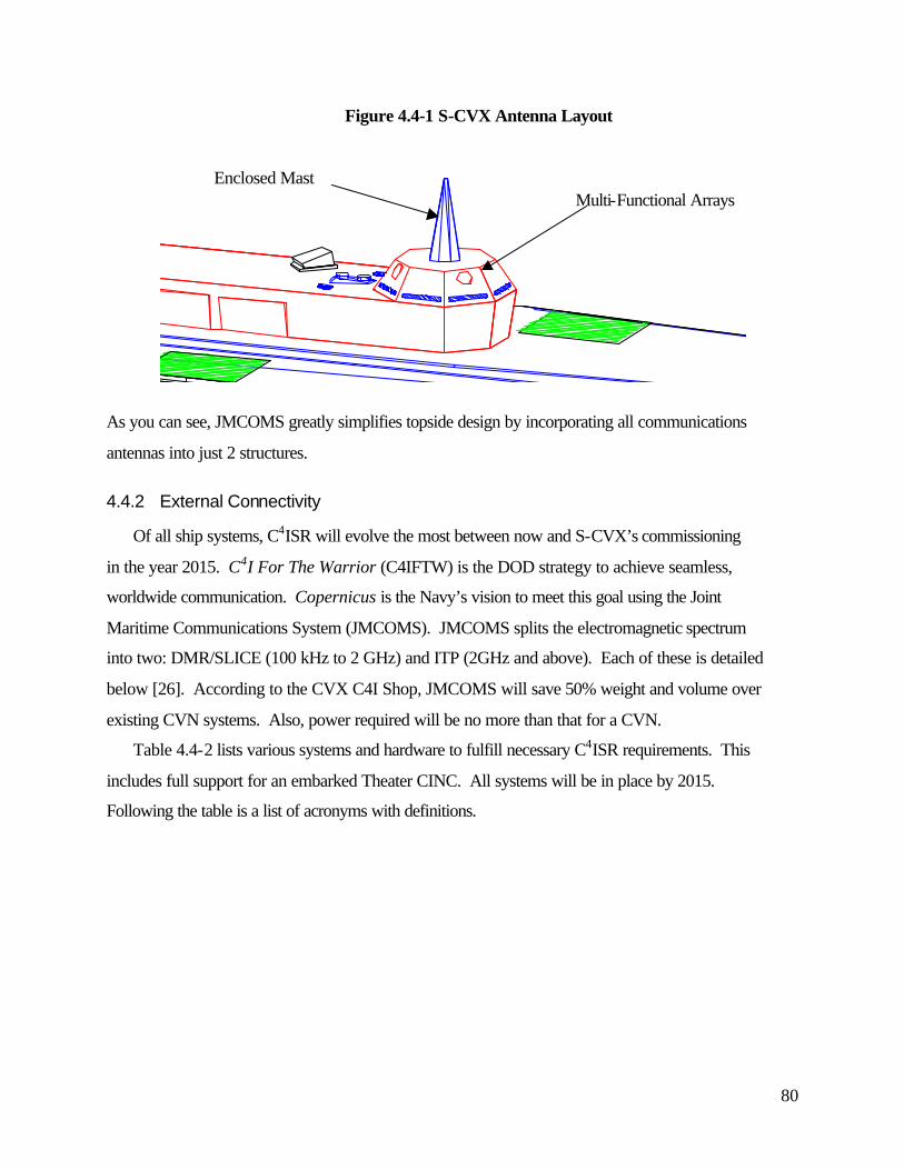
80
Figure 4.4-1 S-CVX Antenna Layout
As you can see, JMCOMS greatly simplifies topside design by incorporating all communications
antennas into just 2 structures.
4.4.2 External Connectivity
Of all ship systems, C4ISR will evolve the most between now and S-CVX’s commissioning
in the year 2015. C4I For The Warrior (C4IFTW) is the DOD strategy to achieve seamless,
worldwide communication. Copernicus is the Navy’s vision to meet this goal using the Joint
Maritime Communications System (JMCOMS). JMCOMS splits the electromagnetic spectrum
into two: DMR/SLICE (100 kHz to 2 GHz) and ITP (2GHz and above). Each of these is detailed
below [26]. According to the CVX C4I Shop, JMCOMS will save 50% weight and volume over
existing CVN systems. Also, power required will be no more than that for a CVN.
Table 4.4-2 lists various systems and hardware to fulfill necessary C4ISR requirements. This
includes full support for an embarked Theater CINC. All systems will be in place by 2015.
Following the table is a list of acronyms with definitions.
Enclosed Mast Multi-Functional Arrays
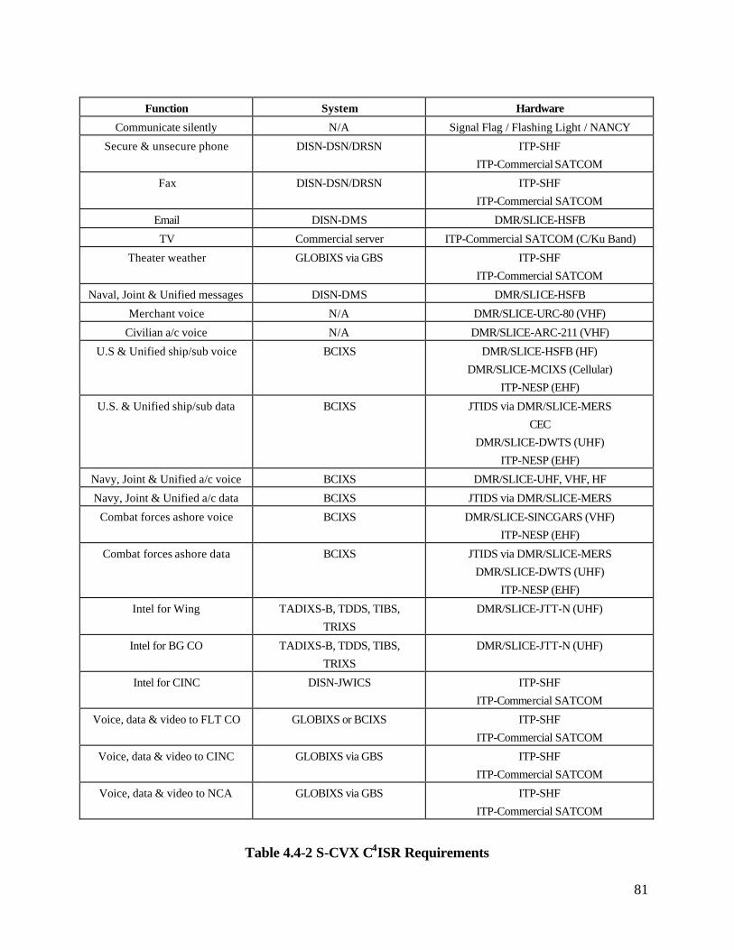
81
Function System Hardware
Communicate silently N/A Signal Flag / Flashing Light / NANCY
Secure & unsecure phone DISN-DSN/DRSN ITP-SHF
ITP-Commercial SATCOM
Fax DISN-DSN/DRSN ITP-SHF
ITP-Commercial SATCOM
Email DISN-DMS DMR/SLICE-HSFB
TV Commercial server ITP-Commercial SATCOM (C/Ku Band)
Theater weather GLOBIXS via GBS ITP-SHF
ITP-Commercial SATCOM
Naval, Joint & Unified messages DISN-DMS DMR/SLICE-HSFB
Merchant voice N/A DMR/SLICE-URC-80 (VHF)
Civilian a/c voice N/A DMR/SLICE-ARC-211 (VHF)
U.S & Unified ship/sub voice BCIXS DMR/SLICE-HSFB (HF)
DMR/SLICE-MCIXS (Cellular)
ITP-NESP (EHF)
U.S. & Unified ship/sub data BCIXS JTIDS via DMR/SLICE-MERS
CEC
DMR/SLICE-DWTS (UHF)
ITP-NESP (EHF)
Navy, Joint & Unified a/c voice BCIXS DMR/SLICE-UHF, VHF, HF
Navy, Joint & Unified a/c data BCIXS JTIDS via DMR/SLICE-MERS
Combat forces ashore voice BCIXS DMR/SLICE-SINCGARS (VHF)
ITP-NESP (EHF)
Combat forces ashore data BCIXS JTIDS via DMR/SLICE-MERS
DMR/SLICE-DWTS (UHF)
ITP-NESP (EHF)
Intel for Wing TADIXS-B, TDDS, TIBS,
TRIXS
DMR/SLICE-JTT-N (UHF)
Intel for BG CO TADIXS-B, TDDS, TIBS,
TRIXS
DMR/SLICE-JTT-N (UHF)
Intel for CINC DISN-JWICS ITP-SHF
ITP-Commercial SATCOM
Voice, data & video to FLT CO GLOBIXS or BCIXS ITP-SHF
ITP-Commercial SATCOM
Voice, data & video to CINC GLOBIXS via GBS ITP-SHF
ITP-Commercial SATCOM
Voice, data & video to NCA GLOBIXS via GBS ITP-SHF
ITP-Commercial SATCOM
Table 4.4-2 S-CVX C4ISR Requirements
82
Defense Information System Network (DISN) - The DOD phone, fax, message and email
system of the future. Consists of Defense Switched Network (DSN), Defense Red Switch
Network (DRSN), Defense Message System (DMS) and the Joint Worldwide Intelligence
Communications System (JWICS).
Global Information Exchange System (GLOBIXS) - DOD system which connects the Theater
CINC to his Tactical Command Centers (BG Commander, Amphibious Commander, JFAC,
etc.).
Battlecube Information Exchange System (BCIXS) - DOD system which connects all joint
forces within the battlecube (i.e. theater of combat operations).
Digital Modular Radio (DMR/SLICE):
1. Handles everything from 100 kHz to 2 GHz.
2. High Speed Fleet Broadcast (HSFB). The HSFB system is a multifunctional system
designed to provide more efficient RF bandwidth utilization and increased data throughput
on the Fleet Broadcast System. It will also significantly improve HF tactical
communications between and among BG/ARG/JTGs and will interface with joint, Allied and
NATO systems.
3. Maritime Cellular Information Exchange Service (MCIXS). MCIXS provides inter- and
intra-BG/ARG/JTG telecommunications by way of cellular telephone trunking. The user
may employ either a standard desktop or cellular telephone to access the trunk.
4. Multi-Functional Eletromagnetic Radiation System (MERS). MERS merges multiple RF
systems (UHF Communications, JTIDS, Combat DF, IFF) into a single, low cost, low
observable, antenna structure.
5. Digital Wideband Transmission System (DWTS). The DWTS provides two UHF, secure,
full duplex, digital wideband transmission links ship-to-ship or ship-to-shore. These links are
high data rate capable and interoperable with U.S. Forces ashore.
6. Single Channel Ground to Air Radio System (SINCGARS). SINCGARS provides VHF-
Frequency Modulation (FM), anti-jam, and 2 channel airborne relay for over-the-horizon
communications for Naval Surface Fire Support (NSFS) and amphibious operations.
83
7. Joint Tactical Terminal-Navy (JTT-N). The JTT-N will be a single multi-configured
terminal and will receive tactical intelligence via UHF communication links for TADIXS B,
TRAP Data Dissemination System (TDDS), Tactical Intelligence Broadcast System (TIBS),
Tactical Reconnaissance Information Exchange System (TRIXS) and transmitting tactical
intelligence via UHF for TIBS and TRIXS.
Integrated Terminal Program (ITP):
1. Spectrum covers 2 GHz and above.
2. Navy EHF SATCOM (NESP). EHF SATCOM provides jointly interoperable low data rate
and future medium and high data rate anti-jam, low probability of intercept/detection
connectivity for submarines, ships and ashore.
3. SHF SATCOM. SHF SATCOM provides high capacity connectivity over the Defense
Satellite Communications System (DSCS) and NATO SHF series satellites. In the fleet, it is
the primary military band ship to shore termination for providing two-way dialing voice for
DSN access, DISN IP network services (SIPRNET, NIPRNET, JWICS), video
teleconferencing and other point to point services.
4. Commercial SATCOM. The commercial SATCOM program provides for low to high
capacity connectivity not supported by military satellite capacity to meet non-tactical,
personal-use or official-use surge capacity requirements. INMARSAT, and transponded C,
Ku and future Ka or Personal Communications Service (PCS) or Multiple Subscriber Service
satellite connectivity will be implemented. Commercial SATCOM normally supports ship to
shore connectivity for point-to-point services similar to SHF SATCOM.
5. Global Broadcast Service (GBS). A joint program to field a very high capacity military
broadcast service worldwide. It is a three phase program. Phase 1 uses commercial satellites
to implement a Joint Broadcast Service (JBS). Phase 2 launches GBS Ka band payloads on
three satellites. Phase 3 completes a worldwide satellite constellation. Ship, ground and
airborne terminal systems and shore based broadcast injection points will be fielded.
6. Multifunction Radar. In addition to performing conventional radar, EW passive & active
functions, these arrays will serve as antennas for all ITP systems. According to the Office of
Naval Research-Radar Division, these arrays will be approximately 3x3 meters.
84
Automated Digital Network System (ADNS):
1. It is the network that connects the user to DMR/SLICE and/or ITP.
2. User connects to ADNS via PCs using IT-21 architecture.
3. Provides seamless, secure multimedia connectivity for voice, video, and data applications.
4. Automates routing and switching functions.
5. Multiplexes all traffic types over available Radio Frequency (RF) asset.
Consolidates radio room space, equipment, and antennas.
4.4.3 Defense Systems
Per the MNS, S-CVX will always operate in company with a minimum of two Aegis
cruisers/destroyers and a least one SSN. These escort assets and carrier air wing will provide the
main component of the battle group defense, especially at long range. S-CVX will only be
equipped with self defense systems.
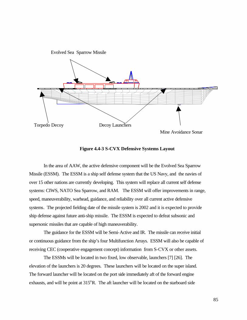
85
Mine Avoidance Sonar
Figure 4.4-3 S-CVX Defensive Systems Layout
In the area of AAW, the active defensive component will be the Evolved Sea Sparrow
Missile (ESSM). The ESSM is a ship self defense system that the US Navy, and the navies of
over 15 other nations are currently developing. This system will replace all current self defense
systems: CIWS, NATO Sea Sparrow, and RAM. The ESSM will offer improvements in range,
speed, maneuverability, warhead, guidance, and reliability over all current active defensive
systems. The projected fielding date of the missile system is 2002 and it is expected to provide
ship defense against future anti-ship missile. The ESSM is expected to defeat subsonic and
supersonic missiles that are capable of high maneuverability.
The guidance for the ESSM will be Semi-Active and IR. The missile can receive initial
or continuous guidance from the ship’s four Multifunction Arrays. ESSM will also be capable of
receiving CEC (cooperative engagement concept) information from S-CVX or other assets.
The ESSMs will be located in two fixed, low observable, launchers [7] [26]. The
elevation of the launchers is 20 degrees. These launchers will be located on the super island.
The forward launcher will be located on the port side immediately aft of the forward engine
exhausts, and will be point at 315oR. The aft launcher will be located on the starboard side
Evolved Sea Sparrow Missile
Decoy Launchers Torpedo Decoy
86
immediately forward of the aft engine exhausts, and will be pointed at 135oR. This large
separation of launchers increases the survivability of this capability. This launcher arrangement,
and the high mobility of the ESSM will provide compete 360o coverage. The launchers are
trained along expected minimal ship radar cross section bearings. In a defensive posture, S-CVX
would maneuver to place the threat on these axes to minimize the ship’s signature and provide a
direct line of fire for the ESSM. These bearings are also the bearings that offer the passive
decoys the greatest probability of success. Furthermore, placing the launcher locations near
existing structures will reduce overall ship RCS because the launcher and the RCS of nearby
structures may overlap at certain angles of orientation. The missile exhaust from the aft launcher
may interfere with the aft engine intakes, and this area needs further investigation.
Each launcher is composed of four, quad missile packs providing a total of 32 ESSM.
These missiles are in sealed canisters to increase their reliability (95%) and can only be reloaded
in port. A CVN76 study of ship defenses determined that this number of ready missiles was
adequate protection for most scenarios.
The ESSM will also have a ASUW mode. This should provide a quick defense against
surface threats out to the maximum line of sight range. The improved warhead of the missile
should make it a credible weapon against most hostile threats, especially smaller combatants.
ASW defense will be provided by the escorts, but CVX will have a passive torpedo
defense. This passive defense will come from a decoy that is a NIXIE derivative. Other defenses
including a possible active anti-torpedo defense and mine defensive system will be discussed in
later sections.
4.4.4 Decoy and Deception Systems
CVX will have an assortment of self-defense systems to counter the anti-ship missile
threat. The carrier will depend on its escorts for theater ballistic missile defense. SLQ-32 V(X)
(follow on variants or equivalent) will provide ESM, ECM, and ECCM functions. Softkill
decoys will be chaff, IR, NULKA and SLQ-49 (rubber duck). All decoys will be supported by
the MK 53 Decoy Launch System (DLS). The MK 53 DLS has the following components:
• MK 23 Decoy Launch Processor (DLP)
• MK 174 Processor Power Supply (PPS)
87
• (2) MK 137 Mod 7 Launchers
• (2) Ready Service Locker
Launcher controls are located on both the bridge and CIC.
All decoys systems will be integrated with the ESM/ECM system, which is an integral
part of the Combat system suite. The entire countermeasure system can be automated, semi-
automated, (automated response recommendation, but manual decision making), or completely
manual [28].
The SLQ-32 will be integrated into the multi-array radar. The MK 23 launcher will be
located on the super island, starboard side, and will fire to starboard to minimize the possibility
of hitting aircraft on landing approach. The rubber duck launchers will be located on the
quarters.
The current SLQ-32 system has deficiencies that should be overcome by the time they are
fielded on the S-CVX. Although the rubber duck offers good broadband RF deception, their lack
of mobility makes them vulnerable to detection. Current IR (TORCH) decoys are non-mobile
and may not provide enough IR energy output to mask a carrier. Possible solutions for
countering the increasing threat from IR anti-ship missile are active IR jamming capability and
additional passive IR deception technique. One possible passive defense may be to use a
controlled water screen over hot surface areas (engine compartments and stacks area) that will
help reduce the overall ship IR signature. This water screen system, in conjunction with stack
gas cooling system, and the countermeasure wash-down system will reduce the ship’s IR
signature and increase the effectiveness of IR decoys.
S-CVX will also employ decoys against torpedo threats. These could include a SLQ-36
Nixie or derivative and an active anti-torpedo torpedo system. There is currently a strong push
for the development of such an active torpedo defense system. If such a system is developed by
the time of the S-CVX, then it should definitely be part of the S-CVX defense system. We
estimate that such a system will require minimal space and weight requirements. The arrays are
mounted on the skin of the ship and would require minimal addition structural or space
requirements. The torpedo compartment where the defensive torpedo will be located will require
a space approximately 10ft by 20ft. This compartment will house the launchers, supporting
equipment, and a ready service magazine. Additional defensive torpedoes will be stored in the
main magazines. The system will consist of four passive arrays, one located on each ship quarter
88
and designed to listen for the high frequency of the torpedo screws and active sonar. The active
anti-torpedo torpedo will be located in (3X3) chaff style firing banks amidships. The torpedo
banks will be bottom firing to provide complete semi-hemispheric coverage.
4.4.5 Mine Avoidance Sonar
Traditionally aircraft carriers have not been equipped with an organic sonar system.
Partly this was due to the limited mine threat posed by the blue water engagements for which
they were primarily designed. As operations are increasingly in the littorals, however, the
danger of mine attacks is increased. Some U.S. warships struck mines during the Gulf War and
the events leading up to it and while none of them sank, they were damaged sufficiently to be
considered a mission kill. In our design for S-CVX we recognized that with the limited number
of carrier assets, the loss of one carrier to a mine attack could provide the difference in future
engagements. We therefore endeavored to equip S-CVX with a state of the art mine avoidance
sonar. Yet before we could lock this system into the final design we needed to satisfy two basic
questions:
1. Could a mine avoidance sonar be deployed with the ability to detect projected surface
and near surface mines at a range sufficient to allow the S-CVX to stop before
detonating the mine?
2. Could the same sonar be designed with a transmit power level low enough so as to not
raise the detection probability of the carrier by submarine threats?
These issues are addressed in detail in appendix D-1. The final result was that, yes, a mine
avoidance sonar is indeed feasible for the S-CVX and has been incorporated into the final design.
4.4.6 Computer and Communications Architecture
In order to provide the decreased manning levels and increased functionality proposed in
the rest of the S-CVX design, an integrated and robust computer and communications
architecture was required. In designing our system, we based our efforts on existing initiatives in
the New Attack Submarine (NSSN), LPD-17 and CVN-76 programs. Our design goes beyond
these systems in that we intend to also incorporate the ship’s interior communications (IC) and
announcing systems and the ship’s entertainment systems (e.g. cable TV) into the same
89
infrastructure. Our goal in S-CVX is to make one more redundant, flexible and more reliable
network than the multiple independent networks of these previous designs.
4.4.6.1 Topology
To define the requirements for the S-CVX computer and communications architecture,
we used studies from the NSSN computer architecture definition effort [3][4][5][6] to define the
required topology needed for S-CVX and to scale the size of our expected network traffic flows.
In performing these scaling operations, several assumptions about the computer and
communications architecture were made. These were:
• OC-12 technology will be available.
• A federated approach will be used in designing this system whereby all major subsystems
will maintain their own LANs independent of the main computer and communications
architecture.
• The computer and communications architecture will be used mostly for inter-systems
communications.
• Since sonar is not a main sensor source for the S-CVX the data rate required will be
approximately the same as that needed for NSSN.
• Data rate needed for communications will be approximately 100 times that of the NSSN to
support the needs of S-CVX and the embarked staff.
• The crew size of the S-CVX is roughly 20 times the size of NSSN so administration and
training needs scale accordingly.
• Command and control data rate will be approximately 20 times that of the NSSN to support
the needs of S-CVX and embarked staff
• S-CVX will need many cameras to view flight deck and pit operations remotely as well as
the surrounding sea to enable remote operation of the ship. The scale factor will be
approximately 20 times the data rate of NSSN.
• Navigation information will transmitted to more stations thus requiring approximately 10
times the data rate of NSSN.
• ESM will be used all of the time, thus requiring 50 times the data rate of the NSSN.
• Engineering and monitoring includes the ICAS, DCS, and SMCS systems used on S-CVX
requiring a factor of 100 to scale the data rate.

90
• There will be a large increase in the amount of radar data generated, requiring a scale factor
of 100 from NSSN.
Table 4.4-4 shows the results of our scaling analyses and the aggregate peak network load we
forecast of 67.6 Gbps (67.6 x 109 bits per second).
Source Reference Data
Rate
Mbits/sec
Scale
Factor
S-CVX Data
Rate
Mbits/sec
Sonar 1705 1 1705
Communications 496 100 49600
Administration 10 20 200
Training 160 20 3200
Command and
Control
100 20 2000
Imagery 340 20 6800
Navigation 170 10 1700
ESM 8 50 400
Engineering/monitor
ing
14 100 1400
Radar 6 100 600
Total: 3009 67605
Table 4.4-4: Peak network load calculations for S-CVX
To support this required data load, we utilize a scaled version of the Asynchronous
Transfer Mode (ATM) mesh network proposed for NSSN. The NSSN studies recommend a 4
ATM switch network to support their required traffic. The S-CVX data load is about 22.5 times
larger than that of the NSSN but NSSN assumes OC-3 (155Mbps) interconnection links between
its switches while for S-CVX we assume OC-12 (622Mpbs) technology will be fully mature and
available. These two factors mandate an S-CVX network containing 22.5 ATM switches. To
91
account for the addition of IC voice and announcing systems (low data rate but high priority
traffic) and the ship’s entertainment system (high data rate but limited distribution and low
priority traffic) as well as to leave room for growth we double the number of required switches to
45.
4.4.6.2 Reliability Considerations
To improve the reliability of the computer and communications architecture we employ
several initiatives. First, all links from the subsystems to the main network are balanced as much
as possible between the various switches in the system. This reduces the loss effects felt by any
one switch being lost. Second, all messages on the computer and communications architecture
will contain a two bit priority code. One of these bits is the priority bit already built into the
ATM cell format. The second is added by us by stripping off the highest address bit in the ATM
cell format. This is easily done because the number of addressable destinations on a ship is far
below the address capacity for ATM switching. By employing this priority encoding scheme we
can better utilize dynamic routing in the ATM switches. Thus when the network becomes
congested due to faults or battle damage, the switches can intelligently decide which messages to
discard while minimizing overall impact to the ship. Last, our proposed system will utilize a
principle we call 2 near/2 far with regard to its inter-switch connection scheme. Under this
principle, every switch in the network will be connected to at least two other switches in the
same general region of the ship as well as two other switches in more distant locations. Thus if a
single switch loses both of its links to the more remote switches, it could still reroute its
messages through the local links and allow those switches to forward the message. Another
advantage of this layout is that under normal, non-fault conditions message latency is reduced as
the number of switches a message must hop through to reach its destination is reduced.
4.4.6.3 Future Growth
Even though we attempted to account for growth in the sizing of our system, we fully
realize that technology is constantly increasing the bandwidth demands of computer networks.
To address this we intend to build the fiber optic cable plant that connects all of this networking
hardware together with large amounts of extra bandwidth potential. Protocols for transfer rates
over fiber of up to 2 Gbps already exist but the switches to implement this are either not yet
developed or prohibitively expensive. By ensuring our installed fiber optic cables are capable of

92
these higher data rates, we can make future upgrades as easy as replacing the installed ATM
switches (once they become available and affordable that is).
4.5 Hull Mechanical and Electrical (HM&E) Systems Design
The S-CVX HM&E systems and their standalone capabilities were researched and
determined by the TSSE design team. Once each system’s capabilities was decided its
characteristics were used as inputs into the Advanced Surface Ship Evaluation Tool - ASSET
MONOCV version 4.1.0. For an overview of the systems considered for each HM&E area see
Section 3.3.2 HM&E Feasibility Study.
Conventionally powered by four LM-6000 gas turbine engines and utilizing the Integrated
Power System (IPS) architecture, the S-CVX is capable of a maximum speed of 28 knots.
General characteristic highlights are presented in Table 4.5-1. A complete set of ASSET
generated systems reports is provided as Appendix C-3.
S-CVX General Characteristics
Displacement 80,374 LT
LBP 250 m (820 ft)
Max Beam 40 m (131 ft)
Draft 13.2 m (43 ft)
Flight Deck Dimensions 262.2 m x 72.2 m (860 ft x 240 ft)
Hangar Area 4820 m2
Max Speed 28 knots
Endurance Speed 20
Range @ Endurance Speed 16,000 nm
Table 4.5-1: S-CVX General Characteristics
4.5.1 Integrated Power System
S-CVX uses an Integrated Power System (IPS) to produce power for propulsion and ship’s
services. There are four power generation modules (PGM) consisting of a General Electric LM-

93
6000 gas turbines, each driving a 45 megawatt generator producing AC power. Two of the
PGM’s are located in the forward engine room, the other two in the aft engine room. Two
Caterpillar 3616 Diesel engines, each driving a 4 megawatt generator, provide emergency power
[29]. After going through a rectifier, DC power is distributed by the Zonal Electrical
Distribution System.
4.5.2 DC Zonal Electrical Distribution System
S-CVX distributes electricity via the DC Zonal Electrical Distribution System (DC
ZEDS). DC ZEDS uses two widely separated primary bus ducts to connect zones. This allows
for modular construction and testing of each zone and reduces longitudinal cables (savings in
cost and weight). At maximum speed, the four propulsion motors require 152 megawatts, this
still leaves 11 megawatts of power for ship’s services. A complete load analysis is available in
an ASSET Report “Machinery Module” in Appendix C-3.
4.5.3 Auxiliary Systems
Auxiliary systems onboard S-CVX, like the Reverse Osmosis water makers, Air
Conditioning plants, Fire pumps, Sea Water Service pumps, etc., are of modular construction as
part of the Navy’s Affordability Through Commonality Program. This program should be
implemented before construction on S-CVX begins, and will make auxiliary systems more
affordable by standardization.
4.5.4 Propulsor System
A novel design aspect of the S-CVX is the propulsor. Figure 4.5-2 shows one of the four
360° azimuthing podded electrical propulsion units on S-CVX. Each unit has a 38 megawatt
motor that turns a fixed pitch propeller. Azimuthing pods eliminate the need for long shaftlines,
rudders, thrusters, controllable pitch propellers, and reduction gears while providing tighter
turning circles and greater stopping capability. By operating pods in a pulling mode, a better
wake field is seen resulting in a higher propeller efficiency. In addition, the better wake field
decreases propeller induced vibration and noise levels. Azimuthing pods are a relatively new
concept, but have been used with 20 megawatt motors on passenger vessels. Fixed pods with 40
megawatt motors have been used on European tankers. Therefore, the design team of S-CVX

94
believes that the increase in technology to 38 megawatts for azimuthing pods is feasible at a
moderate risk.
Figure 4.5-2: Azimuthing Electric Propulsion Drive
4.5.5 Power Analysis
S-CVX can achieve its endurance speed, 20 knots, on two propulsion motors. Four
propulsion motors are needed to achieve sustained (26 knots) and maximum (28 knots) speed.
Propulsive coefficients for endurance, sustained, and maximum speed are 0.681, 0.680, and
0.675, respectively. A detailed power analysis is available in an ASSET Report “Performance
Analysis” in Appendix C-3.
4.5.6 Resistance Analysis
The total resistance of the hull at maximum, sustained, and endurance speeds are 6.75,
5.16, and 2.86 meganewtons, respectively. A complete resistance analysis is available in an
ASSET Report “Resistance Module” in Appendix C-3.
4.6 Damage Control Design Efforts
4.6.1 Overview
Damage control on the S-CVX will be based on three main systems, the Damage Control
System (DCS), the Standard Machinery Control System (SMCS), and the Integrated Condition

95
Assessment System (ICAS). These systems will enhance S-CVX’s ability to quickly and
effectively respond to any battle damage that it may receive. Furthermore, the automation
associated with these systems and their automated interaction will reduce manning requirements.
4.6.2 Fire Suppression Systems
Three zonal AFFF sprinkler systems will be on the flight deck. These same systems will
also serve as the ship’s CBR countermeasure washdown system by eliminating foam injection
and using only seawater. In addition there will be remotely operated water cannons on the
superstructure and flight deck edge to augment the sprinkler system. The aircraft salvage crane
will be stowed in Hangar #1 to minimize its impact on the ship RCS. To provide personnel
protection, the stand-by flight deck fire fighting team and its associated trucks and gear will be
positioned in the spaces below the pilothouse [30].
The hangar area will be divided into two compartments by blast doors. Each compartment
will have independent overhead AFFF sprinkler systems [31]. This system increases the ship
survivability by containing any battle damage to only one hangar compartment and minimizing
the possibility of cascading damages. This is especially critical because of the long longitudinal
length of the hangar. The weapons gallery is also divided into several compartments, each with
independent sprinkler systems and separated by quick acting blast doors. This system will help
contain any battle damage to the weapons gallery and prevent mass detonation or expansion of
the casualty into other weapons locations or magazines. There are also installed sprinkler system
along all weapons movement routes and in the magazine compartments.
Each engine room, emergency diesel room, and auxiliary machinery room will have an
overhead sprinkler system as well as other installed fire-fighting equipment. The gas turbine
engines are further enclosed in airtight modules with automatic installed CO2 systems.
4.6.3 DC Deck Location and Flooding Concerns
Our initial design iteration has the waterline midway up the 4th or damage control deck.
This creates a potential flooding danger that is unacceptable. A second design iteration would
investigate options for increasing the freeboard of the ship to bring the DC deck above the water
line.
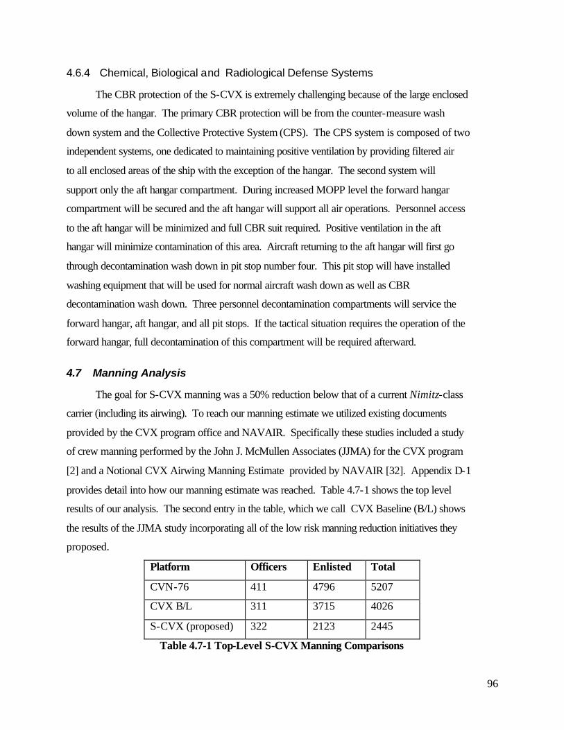
96
4.6.4 Chemical, Biological and Radiological Defense Systems
The CBR protection of the S-CVX is extremely challenging because of the large enclosed
volume of the hangar. The primary CBR protection will be from the counter-measure wash
down system and the Collective Protective System (CPS). The CPS system is composed of two
independent systems, one dedicated to maintaining positive ventilation by providing filtered air
to all enclosed areas of the ship with the exception of the hangar. The second system will
support only the aft hangar compartment. During increased MOPP level the forward hangar
compartment will be secured and the aft hangar will support all air operations. Personnel access
to the aft hangar will be minimized and full CBR suit required. Positive ventilation in the aft
hangar will minimize contamination of this area. Aircraft returning to the aft hangar will first go
through decontamination wash down in pit stop number four. This pit stop will have installed
washing equipment that will be used for normal aircraft wash down as well as CBR
decontamination wash down. Three personnel decontamination compartments will service the
forward hangar, aft hangar, and all pit stops. If the tactical situation requires the operation of the
forward hangar, full decontamination of this compartment will be required afterward.
4.7 Manning Analysis
The goal for S-CVX manning was a 50% reduction below that of a current Nimitz-class
carrier (including its airwing). To reach our manning estimate we utilized existing documents
provided by the CVX program office and NAVAIR. Specifically these studies included a study
of crew manning performed by the John J. McMullen Associates (JJMA) for the CVX program
[2] and a Notional CVX Airwing Manning Estimate provided by NAVAIR [32]. Appendix D-1
provides detail into how our manning estimate was reached. Table 4.7-1 shows the top level
results of our analysis. The second entry in the table, which we call CVX Baseline (B/L) shows
the results of the JJMA study incorporating all of the low risk manning reduction initiatives they
proposed.
Platform Officers Enlisted Total
CVN-76 411 4796 5207
CVX B/L 311 3715 4026
S-CVX (proposed) 322 2123 2445
Table 4.7-1 Top-Level S-CVX Manning Comparisons
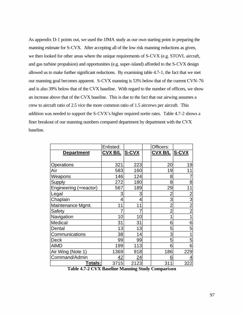
97
As appendix D-1 points out, we used the JJMA study as our own starting point in preparing the
manning estimate for S-CVX. After accepting all of the low risk manning reductions as given,
we then looked for other areas where the unique requirements of S-CVX (e.g. STOVL aircraft,
and gas turbine propulsion) and opportunities (e.g. super-island) afforded to the S-CVX design
allowed us to make further significant reductions. By examining table 4.7-1, the fact that we met
our manning goal becomes apparent. S-CVX manning is 53% below that of the current CVN-76
and is also 39% below that of the CVX baseline. With regard to the number of officers, we show
an increase above that of the CVX baseline. This is due to the fact that our airwing assumes a
crew to aircraft ratio of 2.5 vice the more common ratio of 1.5 aircrews per aircraft. This
addition was needed to support the S-CVX’s higher required sortie rates. Table 4.7-2 shows a
finer breakout of our manning numbers compared department by department with the CVX
baseline.
Enlisted: Officers: Department CVX B/L S-CVX CVX B/L S-CVX
Operations 321 223 20 19 Air 583 160 19 11 Weapons 146 124 8 7 Supply 272 180 8 8 Engineering (+reactor) 567 189 29 11 Legal 3 3 2 2 Chaplain 4 4 3 3 Maintenance Mgmt. 11 11 2 2 Safety 7 7 2 2 Navigation 10 10 1 1 Medical 31 31 6 6 Dental 13 13 5 5 Communications 38 14 3 1 Deck 99 99 5 5 AIMD 199 113 6 6 Air Wing (Note 1) 1369 918 186 229 Command/Admin 42 24 6 4
Totals: 3715 2123 311 322 Table 4.7-2 CVX Baseline Manning Study Comparison
98
As you can see, in many areas we simply accepted the results of the baseline study as is --
usually because the size of the department was so small as to have little impact on the overall
manning of the ship. Some areas of particular interest, however, should be noted.
The 72% reduction in Air Department is due primarily to use of STOVL aircraft on S-
CVX. By eliminating catapults and relegating arrestor gear operations to emergency CTOL
aircraft landing evolutions only, we greatly reduced the required manning numbers. A point to
make here is the arrestor gear, when needed, are manned as collateral duties for personnel from
other divisions. This said, a small contingent of personnel are retained specifically to handle
maintenance issues for the arrestor gear. The other major flight deck initiatives, the use of
TowBots to maneuver aircraft on deck and an automated weapons loading system, also account
for significant manning reductions in the air department.
The 66% reduction in the Engineering Department is due mostly to the use of gas turbine
propulsion by S-CVX. The CVX baseline study still assumes nuclear propulsion for their ship.
Using numbers provided by a separate Navy study, Marine Gas Turbine Propulsion for the Full
Battle Group [33], we were able to radically reduce the required manning. In fact we even added
back 39 enlisted personnel to the number provided by this study because we believed it may have
inadequately addressed needs such as monitoring of electrical distribution and overall system
maintenance.
The proposed airwing for S-CVX is 26% smaller than that suggested in the NAVAIR
Notional CVX Airwing Manning Estimate. Our reductions are gained almost equally as the
result of two factors. First we assumed a lower need for maintenance personnel since S-CVX
will be carrying newer and fewer types of aircraft. Our reduction based on this factor (28.5% of
maintenance personnel) is based on an extrapolation of reductions already seen when one
compares existing F-14 and F/A-18 squadrons. The second reduction initiative we propose is
consolidation of the three embarked JSF squadrons into one JSF wing. Again extrapolating
values from an existing study (this time a NAVAIR study on a composite 12 plane CSA
squadron [34]) we believe a 21.5% decrease in overall squadron manning can be achieved.
In comparing the S-CVX weapons department against the CVX baseline you see only
about a 15% decrease even though we discuss earlier in this paper how the automated weapons
handling system we propose will greatly reduce needed manning. Although this may appear
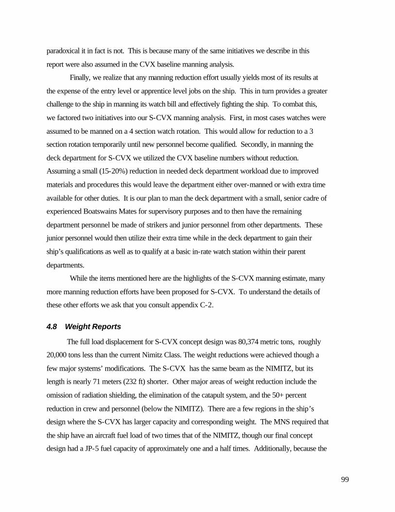
99
paradoxical it in fact is not. This is because many of the same initiatives we describe in this
report were also assumed in the CVX baseline manning analysis.
Finally, we realize that any manning reduction effort usually yields most of its results at
the expense of the entry level or apprentice level jobs on the ship. This in turn provides a greater
challenge to the ship in manning its watch bill and effectively fighting the ship. To combat this,
we factored two initiatives into our S-CVX manning analysis. First, in most cases watches were
assumed to be manned on a 4 section watch rotation. This would allow for reduction to a 3
section rotation temporarily until new personnel become qualified. Secondly, in manning the
deck department for S-CVX we utilized the CVX baseline numbers without reduction.
Assuming a small (15-20%) reduction in needed deck department workload due to improved
materials and procedures this would leave the department either over-manned or with extra time
available for other duties. It is our plan to man the deck department with a small, senior cadre of
experienced Boatswains Mates for supervisory purposes and to then have the remaining
department personnel be made of strikers and junior personnel from other departments. These
junior personnel would then utilize their extra time while in the deck department to gain their
ship’s qualifications as well as to qualify at a basic in-rate watch station within their parent
departments.
While the items mentioned here are the highlights of the S-CVX manning estimate, many
more manning reduction efforts have been proposed for S-CVX. To understand the details of
these other efforts we ask that you consult appendix C-2.
4.8 Weight Reports
The full load displacement for S-CVX concept design was 80,374 metric tons, roughly
20,000 tons less than the current Nimitz Class. The weight reductions were achieved though a
few major systems’ modifications. The S-CVX has the same beam as the NIMITZ, but its
length is nearly 71 meters (232 ft) shorter. Other major areas of weight reduction include the
omission of radiation shielding, the elimination of the catapult system, and the 50+ percent
reduction in crew and personnel (below the NIMITZ). There are a few regions in the ship’s
design where the S-CVX has larger capacity and corresponding weight. The MNS required that
the ship have an aircraft fuel load of two times that of the NIMITZ, though our final concept
design had a JP-5 fuel capacity of approximately one and a half times. Additionally, because the
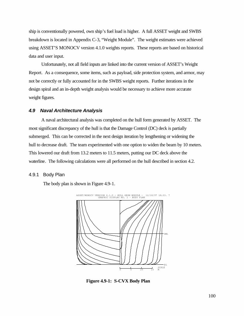
100
ship is conventionally powered, own ship’s fuel load is higher. A full ASSET weight and SWBS
breakdown is located in Appendix C-3, “Weight Module”. The weight estimates were achieved
using ASSET’S MONOCV version 4.1.0 weights reports. These reports are based on historical
data and user input.
Unfortunately, not all field inputs are linked into the current version of ASSET’s Weight
Report. As a consequence, some items, such as payload, side protection system, and armor, may
not be correctly or fully accounted for in the SWBS weight reports. Further iterations in the
design spiral and an in-depth weight analysis would be necessary to achieve more accurate
weight figures.
4.9 Naval Architecture Analysis
A naval architectural analysis was completed on the hull form generated by ASSET. The
most significant discrepancy of the hull is that the Damage Control (DC) deck is partially
submerged. This can be corrected in the next design iteration by lengthening or widening the
hull to decrease draft. The team experimented with one option to widen the beam by 10 meters.
This lowered our draft from 13.2 meters to 11.5 meters, putting our DC deck above the
waterline. The following calculations were all performed on the hull described in section 4.2.
4.9.1 Body Plan
The body plan is shown in Figure 4.9-1.
BL
DWL
0 5 10 15 MSCALE
ASSET/MONOCV VERSION 4.1.0 - HULL GEOM MODULE - 12/18/97 18:33. 7GRAPHIC DISPLAY NO. 1 - BODY PLAN
Figure 4.9-1: S-CVX Body Plan
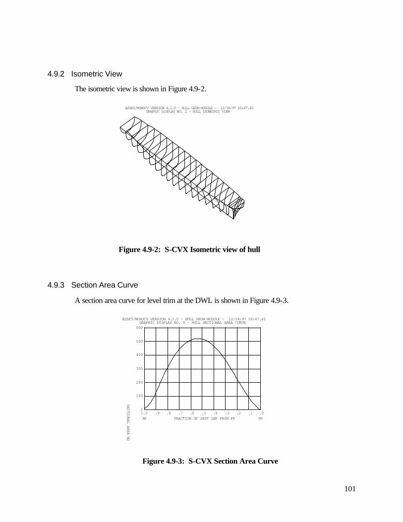
101
4.9.2 Isometric View
The isometric view is shown in Figure 4.9-2.
ASSET/MONOCV VERSION 4.1.0 - HULL GEOM MODULE - 12/18/97 20:47.43GRAPHIC DISPLAY NO. 2 - HULL ISOMETRIC VIEW
Figure 4.9-2: S-CVX Isometric view of hull
4.9.3 Section Area Curve
A section area curve for level trim at the DWL is shown in Figure 4.9-3.
1.0 .9 .8 .7 .6 .5 .4 .3 .2 .1 .00
100
200
300
400
500
600
SECTIONAL AREA M2
FRACTION OF SHIP LBP FROM FPAP FP
ASSET/MONOCV VERSION 4.1.0 - HULL GEOM MODULE - 12/18/97 20:47.43GRAPHIC DISPLAY NO. 5 - HULL SECTIONAL AREA CURVE
Figure 4.9-3: S-CVX Section Area Curve
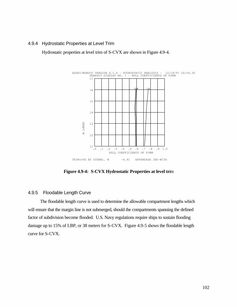
102
4.9.4 Hydrostatic Properties at Level Trim
Hydrostatic properties at level trim of S-CVX are shown in Figure 4.9-4.
.0 .1 .2 .3 .4 .5 .6 .7 .8 .9 1.011
12
13
14
15
16
17
CP CWCB
HULL COEFFICIENTS OF FORMDRAFT M
ASSET/MONOCV VERSION 4.1.0 - HYDROSTATIC ANALYSIS - 12/18/97 20:56.30GRAPHIC DISPLAY NO. 1 - HULL COEFFICIENTS OF FORM
TRIM(+VE BY STERN), M -4.91 APPENDAGE IND-WITH
Figure 4.9-4: S-CVX Hydrostatic Properties at level trim
4.9.5 Floodable Length Curve
The floodable length curve is used to determine the allowable compartment lengths which
will ensure that the margin line is not submerged, should the compartments spanning the defined
factor of subdivision become flooded. U.S. Navy regulations require ships to sustain flooding
damage up to 15% of LBP, or 38 meters for S-CVX. Figure 4.9-5 shows the floodable length
curve for S-CVX.
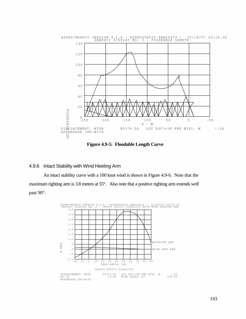
103
-500501001502002500
20
40
60
80
100
120
140
.90
X - M
FLOODABLE LENGTH M
ASSET/MONOCV VERSION 4.1.0 - HYDROSTATIC ANALYSIS - 12/18/97 20:56.30GRAPHIC DISPLAY NO. 3 - FLOODABLE LENGTH
DISPLACEMENT, MTON 80374.06 LCG LOC(+VE FWD MID), M -.26APPENDAGE IND-WITH
Figure 4.9-5: Floodable Length Curve
4.9.6 Intact Stability with Wind Heeling Arm
An intact stability curve with a 100 knot wind is shown in Figure 4.9-6. Note that the
maximum righting arm is 3.8 meters at 55°. Αlso note that a positive righting arm extends well
past 90°.
-20 -10 0 10 20 30 40 50 60 70 80 90-1.0
-.5
.0
.5
1.0
1.5
2.0
2.5
3.0
3.5
4.0
RIGHTING ARM
WIND HEEL ARM
HEEL ANGLE, DEG
ARMS M
ASSET/MONOCV VERSION 4.1.0 - HYDROSTATIC ANALYSIS - 12/18/97 20:56.30GRAPHIC DISPLAY NO. 4 - INTACT STATIC STABILITY WITH WIND HEELING ARM
INTACT STATIC STABILITY
DISPLACEMENT, MTON 80374.06 LCG LOC(+VE FWD MID), M -.26KG, M 13.98 WIND SPEED, KT 100.00APPENDAGE IND-WITH
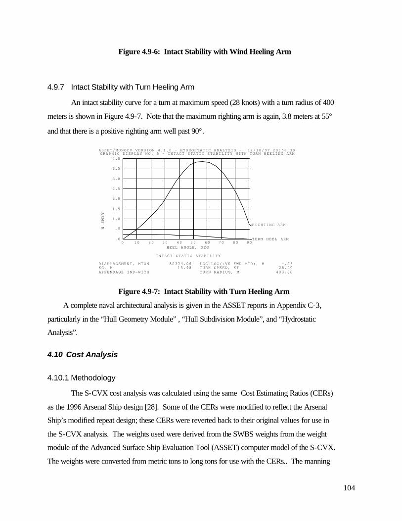
104
Figure 4.9-6: Intact Stability with Wind Heeling Arm
4.9.7 Intact Stability with Turn Heeling Arm
An intact stability curve for a turn at maximum speed (28 knots) with a turn radius of 400
meters is shown in Figure 4.9-7. Note that the maximum righting arm is again, 3.8 meters at 55°
and that there is a positive righting arm well past 90°.
0 10 20 30 40 50 60 70 80 90.0
.5
1.0
1.5
2.0
2.5
3.0
3.5
4.0
RIGHTING ARM
TURN HEEL ARM
HEEL ANGLE, DEG
ARMS M
ASSET/MONOCV VERSION 4.1.0 - HYDROSTATIC ANALYSIS - 12/18/97 20:56.30GRAPHIC DISPLAY NO. 5 - INTACT STATIC STABILITY WITH TURN HEELING ARM
INTACT STATIC STABILITY
DISPLACEMENT, MTON 80374.06 LCG LOC(+VE FWD MID), M -.26KG, M 13.98 TURN SPEED, KT 28.00APPENDAGE IND-WITH TURN RADIUS, M 400.00
Figure 4.9-7: Intact Stability with Turn Heeling Arm
A complete naval architectural analysis is given in the ASSET reports in Appendix C-3,
particularly in the “Hull Geometry Module” , “Hull Subdivision Module”, and “Hydrostatic
Analysis”.
4.10 Cost Analysis
4.10.1 Methodology
The S-CVX cost analysis was calculated using the same Cost Estimating Ratios (CERs)
as the 1996 Arsenal Ship design [28]. Some of the CERs were modified to reflect the Arsenal
Ship’s modified repeat design; these CERs were reverted back to their original values for use in
the S-CVX analysis. The weights used were derived from the SWBS weights from the weight
module of the Advanced Surface Ship Evaluation Tool (ASSET) computer model of the S-CVX.
The weights were converted from metric tons to long tons for use with the CERs.. The manning
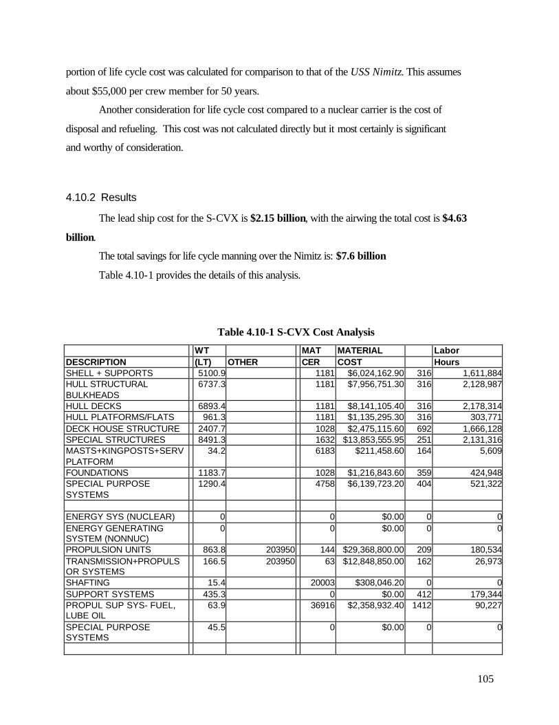
105
portion of life cycle cost was calculated for comparison to that of the USS Nimitz. This assumes
about $55,000 per crew member for 50 years.
Another consideration for life cycle cost compared to a nuclear carrier is the cost of
disposal and refueling. This cost was not calculated directly but it most certainly is significant
and worthy of consideration.
4.10.2 Results
The lead ship cost for the S-CVX is $2.15 billion, with the airwing the total cost is $4.63
billion.
The total savings for life cycle manning over the Nimitz is: $7.6 billion
Table 4.10-1 provides the details of this analysis.
Table 4.10-1 S-CVX Cost Analysis
WT MAT MATERIAL Labor DESCRIPTION (LT) OTHER CER COST Hours SHELL + SUPPORTS 5100.9 1181 $6,024,162.90 316 1,611,884HULL STRUCTURAL BULKHEADS
6737.3 1181 $7,956,751.30 316 2,128,987
HULL DECKS 6893.4 1181 $8,141,105.40 316 2,178,314HULL PLATFORMS/FLATS 961.3 1181 $1,135,295.30 316 303,771DECK HOUSE STRUCTURE 2407.7 1028 $2,475,115.60 692 1,666,128SPECIAL STRUCTURES 8491.3 1632 $13,853,555.95 251 2,131,316MASTS+KINGPOSTS+SERV PLATFORM
34.2 6183 $211,458.60 164 5,609
FOUNDATIONS 1183.7 1028 $1,216,843.60 359 424,948SPECIAL PURPOSE SYSTEMS
1290.4 4758 $6,139,723.20 404 521,322
ENERGY SYS (NUCLEAR) 0 0 $0.00 0 0ENERGY GENERATING SYSTEM (NONNUC)
0 0 $0.00 0 0
PROPULSION UNITS 863.8 203950 144 $29,368,800.00 209 180,534TRANSMISSION+PROPULSOR SYSTEMS
166.5 203950 63 $12,848,850.00 162 26,973
SHAFTING 15.4 20003 $308,046.20 0 0SUPPORT SYSTEMS 435.3 0 $0.00 412 179,344PROPUL SUP SYS- FUEL, LUBE OIL
63.9 36916 $2,358,932.40 1412 90,227
SPECIAL PURPOSE SYSTEMS
45.5 0 $0.00 0 0
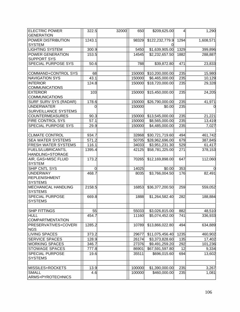
106
ELECTRIC POWER GENERATION
322.5 32000 650 $209,625.00 4 1,290
POWER DISTRIBUTION SYSTEM
1243.1 98329 $122,232,779.90
1294 1,608,571
LIGHTING SYSTEM 300.9 5450 $1,639,905.00 1329 399,896POWER GENERATION SUPPORT SYS
153.5 14545 $2,232,657.50 1882 288,887
SPECIAL PURPOSE SYS 50.6 788 $39,872.80 471 23,833
COMMAND+CONTROL SYS 68 150000 $10,200,000.00 235 15,980NAVIGATION SYS 43.1 150000 $6,465,000.00 235 10,129INTERIOR COMMUNICATIONS
124.8 150000 $18,720,000.00 235 29,328
EXTERIOR COMMUNICATIONS
103 150000 $15,450,000.00 235 24,205
SURF SURV SYS (RADAR) 178.6 150000 $26,790,000.00 235 41,971UNDERWATER SURVEILLANCE SYSTEMS
0 150000 $0.00 235 0
COUNTERMEASURES 90.3 150000 $13,545,000.00 235 21,221FIRE CONTROL SYS 57.1 150000 $8,565,000.00 235 13,419SPECIAL PURPOSE SYS 29.9 150000 $4,485,000.00 235 7,027
CLIMATE CONTROL 934.7 32868 $30,721,719.60 494 461,742SEA WATER SYSTEMS 571.2 50705 $28,962,696.00 679 387,845FRESH WATER SYSTEMS 116.1 34033 $3,951,231.30 529 61,417FUELS/LUBRICANTS, HANDLING+STORAGE
1395.4 42125 $58,781,225.00 271 378,153
AIR, GAS+MISC FLUID SYSTEM
173.2 70265 $12,169,898.00 647 112,060
SHIP CNTL SYS 0 14025 $0.00 353 0UNDERWAY REPLENISHMENT SYSTEMS
468.7 8035 $3,766,004.50 176 82,491
MECHANICAL HANDLING SYSTEMS
2158.5 16853 $36,377,200.50 259 559,052
SPECIAL PURPOSE SYSTEMS
669.8 1888 $1,264,582.40 282 188,884
SHIP FITTINGS 55 55033 $3,026,815.00 882 48,510HULL COMPARTMENTATION
454.7 11160 $5,074,452.00 741 336,933
PRESERVATIVES+COVERINGS
1285.2 10789 $13,866,022.80 494 634,889
LIVING SPACES 373.2 29677 $11,075,456.40 1235 460,902SERVICE SPACES 128.9 26174 $3,373,828.60 135 17,402WORKING SPACES 346.7 27376 $9,491,259.20 292 101,236STOWAGE SPACES 777.8 86901 $67,591,597.80 12 9,334SPECIAL PURPOSE SYSTEMS
19.6 35511 $696,015.60 694 13,602
MISSILES+ROCKETS 13.9 100000 $1,390,000.00 235 3,267SMALL ARMS+PYROTECHNICS
4.6 100000 $460,000.00 235 1,081

107
AIRCRAFT RELATED WEAPONS
813.7 100000 $81,370,000.00 235 191,220
SPECIAL PURPOSE SYSTEMS
133.9 100000 $13,390,000.00 235 31,467
SHIPS FORCE 298.2 MISSION RELATED EXPENDABLES
1603.3
STORES 673.7 LIQUIDS, PETROLEUM BASED
19351.2
LIQUIDS, NON-PETROLEUM BASED
650.3
FUTURE GROWTH MARGIN 453.6 Total Payload weight: 23030.
3
Total 1991 Material Cost: $709,413,485 Total 1997 Material Cost: $847,076,801
Total Reference Labor Hours: 33,474,837 Sum of Labor Hours: 18,016,597
Ship Assembly and Support Labor: Learning Curve Exponent: 95.00% (=0.478*Labor)
Integration and Engineering Labor: Total 1997 Lead Ship Labor Hours:
37,091,202 (=0.186*Labor)
Total 1997 Second Ship Labor Hours:
35,236,656 Program Management Labor:
Total 1997 Third Ship Labor Hours:
34,195,104 (=0.194*Labor)
Total 1997 Fourth Ship Labor Hours:
33,474,837
Total 1997 Fifth Ship Labor Hours:
32,926,618 Total Labor Costs: 33,474,837
Total 1997 Sixth Ship Labor Hours:
32,485,362
1997 Labor Cost per Hour: $25 Total 1997 Lead Ship Labor Cost
$927,280,050
Total 1997 Second Ship Labor Cost:
$880,916,403
Total 1997 Third Ship Labor Cost:
$854,877,611
Total 1997 Fourth Ship Labor Cost:
$836,870,920
Total 1997 Fifth Ship Labor Cost:
$823,165,454
Total 1997 Sixth Ship Labor Cost:
$812,134,058
Non-recurring Engineering Hours:
1300000
Engineering Burdened Rate: $45

108
Non-recurring Engineering Cost:
$58,500,000
Navy Program Cost Factor: 1.00% Total Non-recurring Engineering Cost:
$59,085,000
Shipyard General & Administrative Overhead:
6.50%
Shipyard Insurance: 1.00% Shipyard Contingency: 10.00% Shipyard Profit: 4.00% Total Shipyard Fee + Overhead Rate:
21.50%
Total 1997 Acquisition Costs Nonrecurring Engineering Cost:
$59,085,000
Lead Ship: $2,155,843,574 Second Ship: $2,099,511,742 Third Ship: $2,067,874,611 Fourth Ship: $2,045,996,481 Fifth Ship: $2,029,344,340 Sixth Ship: $2,015,941,194
Estimated Payload Costs: MANNING Total Payload Weight: 23030.3 Nimitz S-CVX Total Payload Cost: $14,900,604 Crew: 5207 2445
$14,319,250,000 $6,723,750,000Sail Away Cost: $2,229,829,178 Diff: $7,595,500,000airwing: $2,400,000,000 Total System Cost: $4,629,829,178
4.11 Conclusions
The design put forth in this report is, we believe, an alternative worth considering for the
future aircraft carrier needs of the Navy and the nation. Our study combines many innovative
approaches that add functionality, reduce manning, meet the unique requirements imposed on
our design (e.g. STOVL, Gas Turbine, Humanitarian/OOW Ops, etc.) and still produce a ship
that shows significant life cycle cost reductions below the current Nimitz-class aircraft carriers.
We understand that our efforts represent only the first iteration in a true design process and that
there are many areas in our design that require further work. This said, we are very confident
that most of the ideas and innovations we propose are feasible. It is our hope that at least some
portion of our efforts may prove useful to the actual CVX design program.

109
4.12 Faculty Assessment of Major Design Innovations
The S-CVX design created by this year’s TSSE students contains several innovative concepts
that deserve repeated mention. Most are not unique to the STOVL-only airwing and provide
such significant benefits that they merit serious consideration for incorporation into any
advanced carrier design. Specifically, the TSSE faculty believes the following concepts deserve
special recognition:
Super-Island with enclosed Pit Stops
One-stop Pit Stops
Tow-Bots for aircraft movement and positioning
Automated weapons handling system
Frame-Kit emergency berthing
Azimuthing pod propulsors
Jet-blast collectors
Enclosed, slant motion elevators
Mine avoidance sonar system
Super-Island with enclosed Pit Stops.
The super-island concept allows all aircraft turn-around functions except landing and take-off to
be performed in a conditioned, protected environment. This significantly reduces the hazard to
the crew and minimizes protective equipment needed. The few crew needed to perform minor
repairs and checkout are shielded from the weather and direct exposure to blast, fragments, flash,
chemical/biological/radiological contamination. Aircraft are provided similar protection.
Because all crew functions are performed within the shelters, they should take less time than in
unprotected environments, reducing turn-around time. Contributions to radar and infrared
signatures from aircraft on deck are reduced (although not eliminated because not all aircraft can
be in the pit stops or in the hangars at one time).

110
One-stop Pit Stops
The TSSE S-CVX concept has pit stops located in the super-island. This is desirable, but not
essential. One-stop pit stops have advantages even when located on exposed locations on the
flight deck. The ability to safely refuel, rearm, make minor electronic repairs, and exchange
flight crews at a single location eliminates the need for movement of aircraft from refueling sites,
to arming sites, etc. Specific fixed locations can have specialized automatic equipment which
can allow multiple functions to be performed in parallel rather than sequentially. This, too, will
reduce turn-around time and permit higher sortie generation rates.
TowBots
The robotic towing and tie-down vehicles called TowBots can eliminate many flight deck
personnel. By eliminating human error and human traffic they can speed up aircraft spotting.
Coupled with automated pit stops they permit the virtual elimination of flight deck personnel
with major improvements in safety and reduction in total manpower.
Automated Weapons Handling System
One of the most manpower-intensive functions on conventional aircraft carriers is the loading,
storage, removal, assembly, movement, attachment to aircraft, and arming of the bombs and
missiles carried by the carrier’s aircraft. The automated system removes the necessity for each
of these tasks to be performed by crew members. Speed of operations can be increased by
removing the human from the loop. The probability of making a mistake in the assembly or
arming which results in failed ordnance during mission will also be reduced. An automated
system will require weapons standardization. This can result in less space devoted to magazines.
The just-in-time character of an automated weapons handling system also means that the
traditional bomb farm around the island can be eliminated with an enormous improvement in
survivability given a concerted bombing or missile attack.
111
Frame-Kit Emergency Berthing
The use of pre-fabricated, specially designed structures which can be stored in limited volumes
and rapidly assembled into large-scale berthing and sanitation facilities for non-combatants or
wounded, deserves serious consideration if missions other than war continue to be commonplace.
It is not practical to devote too much space or resources to these occasional missions. Yet failure
to be prepared could have tragic if not catastrophic consequences, when those missions arise.
Jet Blast Collectors
STOVL aircraft will be developed for naval missions (the Marines will procure a STOVL
version of JSF) even if the Navy procures a CTOL JSF. The engines from such STOVL aircraft
will significantly heat the flight deck. Tire damage and personnel injuries may result. The
impact of the jet blast on the deck will also significantly raise noise levels. By having areas with
cooled grates to collect the STOVL engine down-blast and direct it overboard, both the heating
and noise effects will be significantly ameliorated. STOVL aircraft may also be spotted closer
together because the blast effects are ameliorated.
Enclosed, Slant Motion Elevators
Traditional deck-edge elevators pose three serious limitations on aircraft carriers. Flight
operations must stop when the sea state is high enough to wet the elevator decks with green
water. The openings associated with deck-edge elevators make it nearly impossible to control
the radar cross section presented to cruise missiles and attack aircraft. The openings also make it
difficult to button up the hangar deck to prevent contamination during a chemical, biological, or
radiological (CBR) attack. The openings are usually open regardless of elevator position unless
under the immediate threat of CBR attack. Deck edge elevators are desirable because they do
not limit the deck areas available for landing and take-off operations. The TSSE design team
conceived of elevators which open onto the flight deck at the edges but retract into the hull at a
slant, paralleling the slope of the sponsons. In this design the sponson can totally enclose the
elevator. Radar cross section is determined by the shape of the sponsons, not by the cavity

112
reflectors inside the hangar deck. Because the elevator is totally enclosed, sea state need not
limit flight operations until green water wets the flight deck. Other factors such as wind speed
will probably limit operations before enclosed elevators do. With the elevators closed it is
possible to pressurize the hangar deck and preclude CBR contamination. The only serious
disadvantange of the enclosed, slant-motion elevators is that they will reduce the space available
on the hangar deck. This limitation does not seem to outweigh the advantages.
Mine Avoidance Sonar
Mines are becoming so numerous in the arsenals of our potential enemies that aircraft carriers
will almost certainly encounter mined area. The mined areas need not be localized or located in
traditional choke points. It is possible that mid-ocean transit routes might be mined by enemy
submarines. The United States does not possess the mine-clearing assets to ensure safety during
higher speed operations. Because it would be catastrophic to the Navy to lose a billion-dollar
aircraft carrier to a thousand-dollar mine, some form of mine detection equipment should be
incorporated on every major combatant to permit avoidance of moored or floating mines.
Bottom mines would not be addressed but these are usually more expensive and less common in
deeper waters where major combatants would sail. The simple sonar system conceived by the
TSSE students is merely indicative that a low-powered, high-frequency sonar could be
developed which can localize mines but not increase the carrier’s acoustic signature to levels
detectable to distant submarines, a key additional requirement.

113
5 References
[1] Future Aircraft Carrier Study -- Aircraft Platform Interface (API) Analysis, Hal Fluk, Code
02T, Naval Air Engineering Center, 13 November 1991
[2] CVN 76 Workload Analysis and CVX Baseline Analysis Initial Manning Estimate, John J.
McMullen Associates Inc., 25 October 1996
[3] NSSN C3I System Architecture Description Document, AT&T Corporation, March 1995
[4] NSSN CCCIS Architecture Concept: System Architecture Description Document, BBN
Report No. 8054, BBN Systems and Technologies, March 1995
[5] NSSN C3IS Architect Concept Designer: System Architecture Description Document,
Contract No. SNE 224-027, TRW Corporation, March 1995
[6] NSSN C3I System Architecture Concurrent Engineering Team Final Report, July 1995
[7] Jane’s, Naval Weapon Systems, 1994
[8] Jane’s, Fighting Ships 1994-1995.
[9] Sikova, J., Grassman, J., “Advanced Double Hull Structural Design Technology,” Naval
Engineer’s Journal, May 1997, p. 117-28.
[10] Naval Surface Warfare Center – Carderock Division, Advanced Double Hull and Box
Girders, 1 Aug 1995.
[11] Rains, D., TS 4001 Lecture Notes, May 1997.
[12] CVX Program Office, CVX AOA Part 1, Apr 18 1997.
[13] Decision Engineering, Modern Powerplant Component Characteristics, Jun 3 1991.
[14] General Electric, Marine Gas Turbines: The Task Force, July 1996.
[15] NAVSEA03R2, ICR Gas Turbine Development Program, Jan 5 1994.
[16] Lockheed-Martin, Integrated Power System for the 21st Century, Jun 1996.
[17] NAVSEA 03R2, IPS: Configuration Control for SC-21, Jan 23 1997.
[18] Doerry, N., Robey, H., Amy, J., Petry, C., “Powering the Future with the Integrated Power
System,” Naval Engineer’s Journal, May 1996, p. 267-82.
[19] “Future Electric: Harvesting the promise of IFEP,” Jane’s Navy International, July 1997,
p.14-21.
114
[20] Spotts, T., “IPS system brings Innovation to Naval Ship Designs,” Sea Technology, July
1997, p.23-9.
[21] Wilhemi, G., Appleman, W., “Composite Shafting for Naval Propulsion Systems,” Naval
Engineer’s Journal, July 1986, p. 129-36.
[22] Rains, D., Vanlandingham, D., “Podded Destroyer Propulsion,” Naval Engineer’s Journal,
April 1979, p. 120-9.
[23] Kvaerner Masa-Azipod, Azimuthing Electric Propulsion Drive, Jun 15 1996.
[24] Alexander, K., “Waterjet to Hull Load Transfer,” Naval Engineer’s Journal, May 1996,
p.375-86.
[25] NAVSEA 03R22, Advanced Surface Machinery Program, Sep 23 1994
[26] Cocoon Launching System, TRACOR System Engineering, United Defense, provided by
Bob Scheckler
[27] World Naval Weapons Systems, Norman Friedman, United States Naval Institute, 1989.
[28] An Arsenal Ship Design, Total Ship System Engineering Student Capstone Design Project,
Naval Postgraduate School, April 1997.
[29] Caterpillar, Marine Diesel Selection Guide, Nov 1995.
[30] Aircraft Carrier Reference Data Manual, NAEC-MISC-06900, Naval Air Warfare Center,
Aircraft Division, Lakehurst, 01 January 1994
[31] U.S. Aircraft Carriers, Norman Friedman, United States Naval Institute, 1983.
[32] CVX Preliminary Baseline Manpower Estimate, Airwing and Aviation Functions (working
papers), provided by Bruce Colby of NAVAIR
[33] NAVSEA, Marine Gas Turbine Propulsion For the Full Battlegroup, CVX program office
slide presentation, Jimmy Dunne & LCDR Steve Surko, June 1996.
[34] CSA Notional Squadron Manpower Projections/Estimates (working papers), provided by
Bruce Colby of NAVAIR

115
6 Appendices
A-1 Friendly and Hostile Force Structures for S-CVX Defining Scenario
A-2 Scenario Mission Analysis and Required Aircraft Sorties for S-CVX Defining Scenario
B-1 Island-less Carrier Study
C-1 Mine Avoidance Sonar Analysis
C-2 TSSE S-CVX Baseline Manning
C-3 ASSET Reports
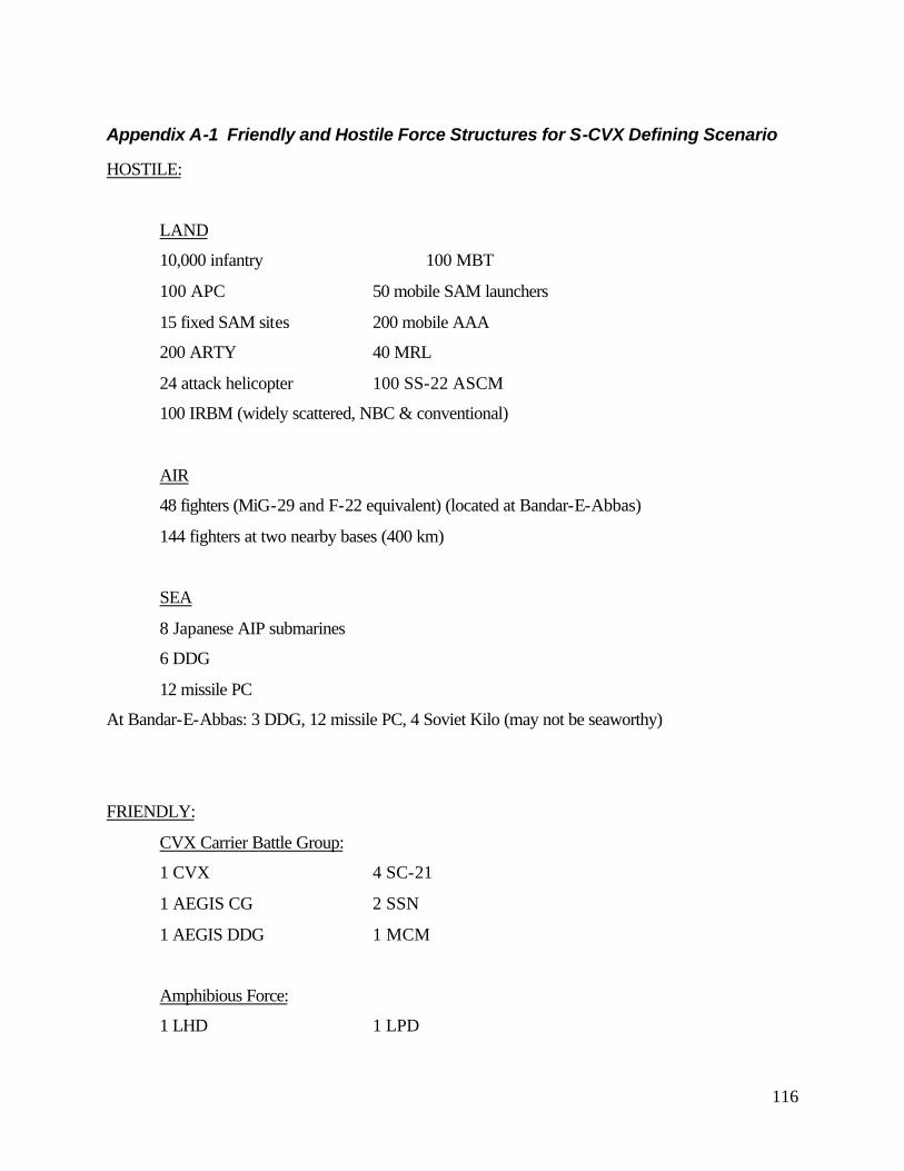
116
Appendix A-1 Friendly and Hostile Force Structures for S-CVX Defining Scenario
HOSTILE:
LAND
10,000 infantry 100 MBT
100 APC 50 mobile SAM launchers
15 fixed SAM sites 200 mobile AAA
200 ARTY 40 MRL
24 attack helicopter 100 SS-22 ASCM
100 IRBM (widely scattered, NBC & conventional)
AIR
48 fighters (MiG-29 and F-22 equivalent) (located at Bandar-E-Abbas)
144 fighters at two nearby bases (400 km)
SEA
8 Japanese AIP submarines
6 DDG
12 missile PC
At Bandar-E-Abbas: 3 DDG, 12 missile PC, 4 Soviet Kilo (may not be seaworthy)
FRIENDLY:
CVX Carrier Battle Group:
1 CVX 4 SC-21
1 AEGIS CG 2 SSN
1 AEGIS DDG 1 MCM
Amphibious Force:
1 LHD 1 LPD
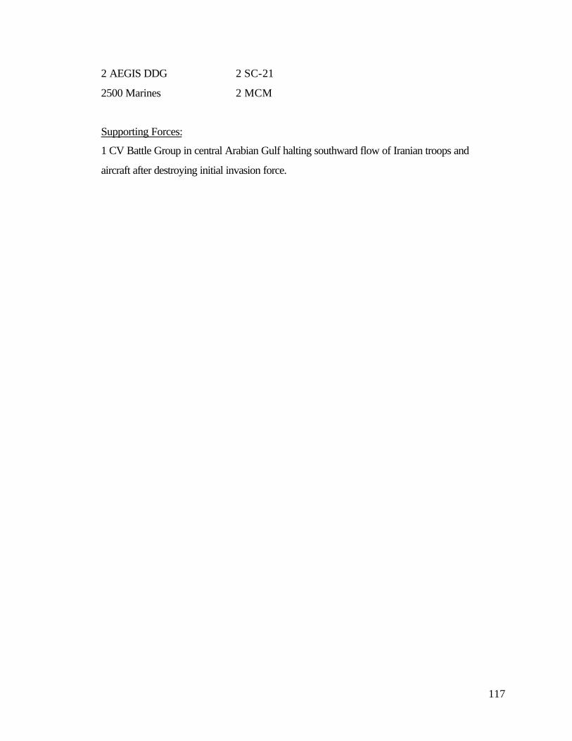
117
2 AEGIS DDG 2 SC-21
2500 Marines 2 MCM
Supporting Forces:
1 CV Battle Group in central Arabian Gulf halting southward flow of Iranian troops and
aircraft after destroying initial invasion force.
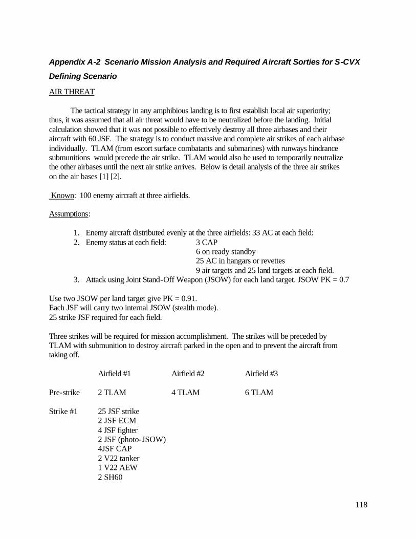
118
Appendix A-2 Scenario Mission Analysis and Required Aircraft Sorties for S-CVX
Defining Scenario
AIR THREAT
The tactical strategy in any amphibious landing is to first establish local air superiority; thus, it was assumed that all air threat would have to be neutralized before the landing. Initial calculation showed that it was not possible to effectively destroy all three airbases and their aircraft with 60 JSF. The strategy is to conduct massive and complete air strikes of each airbase individually. TLAM (from escort surface combatants and submarines) with runways hindrance submunitions would precede the air strike. TLAM would also be used to temporarily neutralize the other airbases until the next air strike arrives. Below is detail analysis of the three air strikes on the air bases [1] [2]. Known: 100 enemy aircraft at three airfields. Assumptions:
1. Enemy aircraft distributed evenly at the three airfields: 33 AC at each field: 2. Enemy status at each field: 3 CAP
6 on ready standby 25 AC in hangars or revettes
9 air targets and 25 land targets at each field. 3. Attack using Joint Stand-Off Weapon (JSOW) for each land target. JSOW PK = 0.7
Use two JSOW per land target give PK = 0.91. Each JSF will carry two internal JSOW (stealth mode). 25 strike JSF required for each field. Three strikes will be required for mission accomplishment. The strikes will be preceded by TLAM with submunition to destroy aircraft parked in the open and to prevent the aircraft from taking off.
Airfield #1 Airfield #2 Airfield #3 Pre-strike 2 TLAM 4 TLAM 6 TLAM Strike #1 25 JSF strike 2 JSF ECM 4 JSF fighter 2 JSF (photo-JSOW) 4JSF CAP 2 V22 tanker 1 V22 AEW 2 SH60
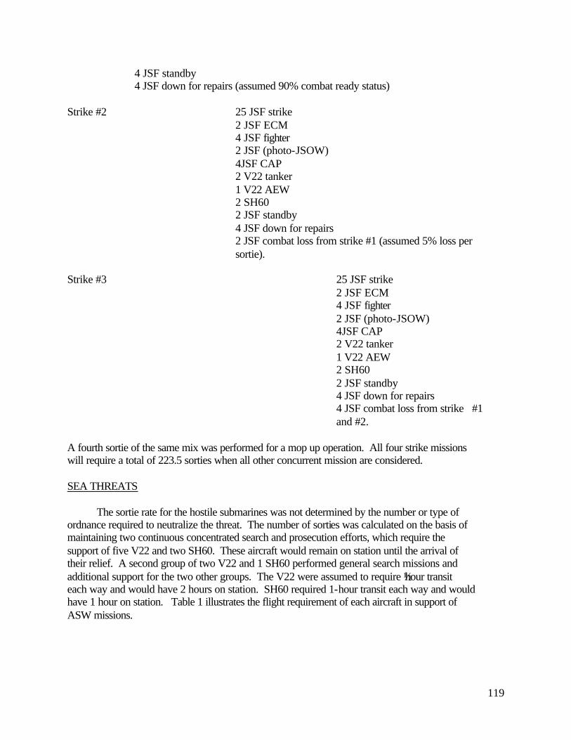
119
4 JSF standby 4 JSF down for repairs (assumed 90% combat ready status) Strike #2 25 JSF strike 2 JSF ECM 4 JSF fighter
2 JSF (photo-JSOW) 4JSF CAP 2 V22 tanker 1 V22 AEW 2 SH60 2 JSF standby 4 JSF down for repairs
2 JSF combat loss from strike #1 (assumed 5% loss per sortie).
Strike #3 25 JSF strike
2 JSF ECM 4 JSF fighter
2 JSF (photo-JSOW) 4JSF CAP 2 V22 tanker 1 V22 AEW 2 SH60 2 JSF standby 4 JSF down for repairs
4 JSF combat loss from strike #1 and #2.
A fourth sortie of the same mix was performed for a mop up operation. All four strike missions will require a total of 223.5 sorties when all other concurrent mission are considered. SEA THREATS
The sortie rate for the hostile submarines was not determined by the number or type of ordnance required to neutralize the threat. The number of sorties was calculated on the basis of maintaining two continuous concentrated search and prosecution efforts, which require the support of five V22 and two SH60. These aircraft would remain on station until the arrival of their relief. A second group of two V22 and 1 SH60 performed general search missions and additional support for the two other groups. The V22 were assumed to require ½ hour transit each way and would have 2 hours on station. SH60 required 1-hour transit each way and would have 1 hour on station. Table 1 illustrates the flight requirement of each aircraft in support of ASW missions.

120
Table 1: ASW Flight Requirments
Threat: 9 DDG -Response: Standoff attack by JSF. -Weapons: Harpoon (assume PK = 0.5) -Required Sortie: Neutralize 100% threat. Assume 3 Harpoon for each DDG, PK = 0.88 Assume 2 Harpoon/JSF = 14 JSF sorties. Threat: 24 Missile PC -Response: Direct attack by JSF -Weapons: Harpoon or Iron Bombs -Required Sortie: Neutralize 100% threat. Assume 2 weapon for each target Assume 4 weapon/JSF = 12 JSF sorties LAND THREATS
Threat: 10,000 infantry
V22 #1 V22 #2 V22 #3 V22 #4 SH60 #1 V22 #5 SH60 #2 V22 #6 V22 #7 SH60 #30 T/OS OS/T T/OS OS/T T/OS T1 OS OS /T T/ OS2 OS/T T/OS OS/T T/OS OS/T T/OS3 OS OS/T T/OS OS4 OS/T T/OS T/ OS /T OS/T T5 OS OS/T T/OS OS6 T/OS OS/T T/OS OS/T T/OS T7 OS OS /T T/ OS8 OS/T T/OS OS/T T/OS T/OS OS/T T/OS9 OS OS/T OS OS
10 OS/T T/OS T/ OS/T /T OS/T T11 OS T/OS OS12 T/OS OS/T T/OS OS/T T/OS T13 OS OS /T T/ OS14 OS/T T/OS OS/T T/OS T/OS OS/T T/OS15 OS OS/T OS OS16 OS/T T/OS T/ OS/T /T OS/T T17 OS T/OS OS18 T/OS OS/T T/OS OS/T T/OS T19 OS OS /T T/ OS20 OS/T T/OS OS/T T/OS T/OS OS/T T/OS21 OS OS/T OS OS22 OS/T T/OS T/ OS/T /T OS/T T23 OS T/OS OS
# of Sortie 12 16 12
CONCETRATED SEARCH AND PROSECUTION ADDITIONAL SEARCH
Hours
ASW Group 1 ASW Group 2 ASW Group 3
Total V22 Sortie 28Total SH60 Sortie 12

121
-Response: Continuing direct air attack of marshaling areas, choke points, and other areas of concentration.
-Weapons: Air deployed cluster bombs and area denial munitions. -Required Aircraft sorties: Neutralized 50% of threat; 5000 infantry assume 100 infantry killed per sortie = 50 JSF sorties. Threat: 100 Main Battle Tanks (MBTs) and 100 Armored Personnel Carriers (APCs) = 200 targets
-Response: Standoff attack of marshalling area, choke points, etc. -Weapons: JSOW B (24 sub-munitions per JSOW); 2 JSOW per JSF.
-Required Aircraft sorties: assume JSOW PK = 0.5 therefore 12 target destroyed per JSOW. To destroy 50% of threat requires 8.5 JSF sorties.
Threat: 15 fixed Surface to Air Missile (SAM) sites
-Response: Standoff attack. -Weapons: JSOW A, Tomahawk, SLAM-ER, JASSM -Required Aircraft sorties: assume 2 weapons per target = 30 weapons total.
Assume 75% will be air-launched weapons = 23 weapons Assume 2 weapons per JSF = 12 JSF sorties.
Threat: 100 mobile Intermediate Range Ballistic Missiles (IRBMs)
-Response: JSF stand off attacks. -Weapons: JSOW A, SLAM-ER (ATR) -Required Aircraft sorties: To destroy 75% of threat
Assume 2 sorties to acquire and destroy each target = 150 JSF sorties.
Threat: 100 SS-22 Anti-Ship Cruise Missiles (ASCMs) -Response: JSF direct attack.
-Weapons: Dumb/Smart bombs. -Required Aircraft sorties: assume 4 bombs/JSF with PK=0.8
= 32 JSF sorties.
Threat: 40 Multiple Rocket Launchers (MRLs) -Response: JSF direct attack
-Weapons: JDAM, PK=0.5 -Required Aircraft sorties: Assume destroy all MRLs with 20 miles of beachhead = 20 MRL. Assume 4 bombs per JSF = 10 JSF sorties.
Threat: 50 Mobile SAM launchers
-Response: JSF (stealth configuration) direct attack -Weapons: HARM and cluster bombs -Required Aircraft sorties: = 25 JSF sorties. Threat: 200 Mobile Anti Aircraft Artillery (AAA)
-Response: JSF direct attack

122
-Weapons: Cluster bombs; PK=0.5; 4 bombs/JSF -Required Aircraft sorties: Assume 50% detection probability = 50 JSF sorties. Threat: 200 ARTILLERY
-Response: JSF direct attack -Weapons: Cluster bombs; PK=0.5; 4 bombs/JSF -Required Aircraft sorties: Assume destroy 50% threat = 50 JSF sorties. Threat: 24 Attack Helicopters
-Response: JSF attack -Weapons: Air-to-Air missile (PK=0.7), Cluster bombs (PK=0.7) , JDAM (PK=0.9)
-Required Aircraft sorties: = Assume 30% kill in Air, 50% soft target on ground, 20% hard ground targets.
8 air target = 6 JSF sorties. 12 ground targets = 12 JSF sorties. References:
[1] Operation Desert Storm, Evaluation of the Air Campaign, GAO/NSIAD-97-134, June 1997,
www.gao.gov.
[2] Joint Strike Fighter Program, www.jast.mil
123
Appendix B-1 Island-less Carrier Study
OVERVIEW
An island-less carrier presents the opportunity to lower ship RCS signatures and increase
launch and recovery flight path options. This study reviews the feasibility of an island-less
CVX design and presents possible solutions to inherent problems posed by removing the island.
While existing CVN island designs support many functions, the crucial functions
identified in this study were aviation control; antenna farm; conning stations; and CO tactical
plot. Several other important functions such as the CO’s cabin, Flag Officer cabin have
traditionally been located on the island, however, as long as the senior officers are provided with
relatively close access to the aforementioned crucial functions, their location does not necessarily
require a bridge and island.
The total deckhouse area of the NIMITZ Class CVN is less than one percent of the total
available area. Incorporating the function spaces lost due to island elimination into the ship hull
and sponsons becomes only an exercise in arrangements. Further, by implementing CVX
manning reduction plans greater flexibility in arrangements may also be possible.
CURRENT CVN ISLAND FUNCTION AREA REQUIREMENTS
The review of functional spaces housed in the carrier island is based the nominal Large
CTOL Asset Carrier. The Asset space module report breaks down the area (m2) and ship
location (deckhouse, hull/sponson, or either) of all the ship’s functions. Table 1 lists the
breakdown of deckhouse function areas. The Large CTOL Carrier total area is 83780 m2 and
the total deckhouse (island) area is 494 m2, yielding a ratio of deckhouse area to total area of
0.57%.* Clearly, finding room for island functions is not a problem. But, functions such as
aviation control and ship control necessarily require the ability to ‘see.’ Removal of the island
calls for a novel approach to fulfill these functional requirements.
The surface area required for the ship’s antennas is a small fraction of the total exposed
surface area (above the waterline) of the CVN. But, relocation becomes a problem for two
primary reasons: first, an unobstructed clear field of view must be maintained; and second, the
potential for irradiating top side personnel must be avoided. Another factor, not considered, is
* All area reports based on the output of Asset’s Nominal Large CTOL CVN model.
124
each system’s horizon range. Horizon range is a function of height above sea level, eliminating
the island would necessarily reduce this range. But, the carrier’s inherent size, flight deck
approximately 60 ft above the sea, mitigates this factor.
OPTIONS FOR AVIATION CONTROL AND SHIP CONNING
To provide a view of the flight deck and local air traffic four options were considered:
1. Balloon/dirigibles equipped with panoramic camera system tethered to the port and
starboard deck edges;
2. Mast mounted panoramic camera system; this option assumes a “super-mast” is used in
the CVX design;
3. Deck edge mounted radar(s) or IRST linked to a computer simulation of the flight deck
and local air space;
4. Dog-house mounted panoramic camera system , IRST, or radar system; this option
assumes a “small” flight deck structure which may house aircraft rapid refuel/reload
facilities and or hangar deck elevator shaft.
Options 1) and 3) assume no flight superstructures whatsoever, while 2) and 4) assume
small optimally shaped structures, i.e., low radar cross section. To accurately assess the
feasibility of these options a breakdown of advantages and disadvantages for each follows.
Balloon System:
Advantages:
1. Real time, non simulated display.
2. Multiple redundancy; two or more balloons and multiple cameras.
3. Output display has look and feel similar to current island’s physical view.
4. Better than current system, 360° degree coverage.
5. Relatively cheap components.
6. Not very technically demanding.
7. Hardwire linked possible, high data rate capability, excellent image quality.
Disadvantages:
1. Questionable ability to operate in high sea states or high winds.
2. May not be a feasible options for ship control during in-port maneuvering.
125
3. Stability of camera system image may fluctuate, decreased ability to follow flight deck
operations.
4. Requires transponder and associated software for exact balloon location and camera
orientation.
5. Possible interference with flight paths.
6. No inherent linkage to computer controlled flight deck and operation management.
Mast Mounted Panoramic Camera System:
Advantages:
Same as balloon system above plus:
1. Flight path interference not an issue, assume super mast is pre-existing.
2. Fixed camera system position.
3. Operate in all winds and sea states.
Disadvantages:
1. Presupposes incorporation of a “super mast.”
2. Possible blind spot at base of mast, therefore, requires deck edge cameras.
3. Mast may not provide high enough elevation for optimal view of flight deck.
4. Shorter horizon than for balloon or radar systems.
Deck Edge Radar(s) or Infrared Search and Track (IRST) and Computer Simulated Flight Deck
Environment
Advantages:
1. Possible to obtain exact coordinates, range, and azimuth of aircraft on flight deck and in local
air space.
2. More easily input/feed to other operations systems, e.g. IFF could identify plane and its
location on flight deck.
3. Computer simulated approach enhances ability to provide training and mock exercises in
flight deck management.
4. System is stable and accurate.
5. No interference with flight path.
6. Good performance in all sea states, except extremely heavy rain or fog.

126
Disadvantages:
1. Possible for enemy intercept of radar.
2. Non-traditional “feel” of computer simulated flight deck, complications with man-machine
interface (MMI).
3. System cost more expensive than the other options.
4. Concern for prolonged exposure of pilots and flight deck crew to deck edge radar.
Dog House Mounted Camera, Radar System, or IRST
Advantages:
1. Higher elevation than deck edge, therefore better horizon range for radar and IRST.
2. Circular scanning possible, multiple systems not required for 360° coverage.
3. Operate in all sea states.
4. Fixed sensor sight and ease of access.
5. Same advantages as Deck Edge Radar, except for some possible flight path interference.
6. Dog house provides larger surface are for sensor mounting and thus greater design flexibility.
Disadvantages:
1. Presupposes incorporation of a “dog house.”
2. Potential for “blind spots” at the base of the dog house, larger blind spot that for mast system.
3. Depending on system chosen, cost and computer user interface may be not be acceptable.
OPTIONS FOR ANTENNA RELOCATION
The island functions as the mounting location for most of the carrier’s antennas
eliminating the island presents some difficulty. Three possible options may be considered for the
next generation carrier: deck mount the antennas; use conformal arrays mounted to the hull and
sponsons; or house all the antennas in a “super mast” structure similar to that proposed for the
SC-21.
Mounting the antennas on the carrier’s deck edge is simplest and cheapest option, but it
would necessarily pose restrictions on flight deck operation areas. Further, there would be an
increased danger to irradiating crew and also there would be a loss in horizon range of the
applicable antennas.
127
Developing hull/sponson mounted conformal arrays for each of the ship’s antennas would
likely be technically feasible by the timeframe of construction. Conformal arrays would provide
added directivity over existing antenna designs and would also mitigate some of the losses due to
the decrease in horizon range associated with the lower mounting location. Development cost
would likely be the obstacle for this option. To obtain 360° coverage, arrays would likely have
to be placed on both the port and starboard side of the ship; this added redundancy would
increase cost, but also would improve system performance.
The set-up to most closely match the current carrier’s antenna configuration would be the
flight deck “dog house” option. The doghouse would provide a covered area for aircraft
refueling and weapons loading and possibly a cover for an inboard elevator. The large surface
area on top of the dog house would allow for relatively easy configuration of a traditional
“antenna farm.” It is assumed that the dog house is designed to minimize radar cross section.
Finally, a “super mast” structure mounted on the flight deck could be used to house the
antennas. The SC-21 design proposes to use such a mast, but the technical feasibility of the
design remains to be proven. However, success of the program would greatly influence the
design for a CVX system. Such a super mast could pose an interference to flight deck
operations, but would have the added benefit of collocating all the antennas and increasing
antenna horizon range.

128
Appendix C-1 Mine Avoidance Sonar Analysis
1. Question. Is a mine avoidance sonar practical given our S-CVX design? Specifically,
a. Can the carrier stop in time?
b. Will the mine avoidance sonar increase the carrier’s detection range by hostile
submarines?
c. Are power requirements reasonable?
d. Are manning requirements reasonable?
2. Assumptions.
a. Normal cruising speed of 15 kts or 8.3 m/s.
b. 4 propulsion pods @ 30MW each.
c. Propeller diameter is 6.2 m.
d. Astern propulsion is 2/3rds that of the forward direction.
e. Ship displacement is 80,000 metric tons.
f. Mine diameter is 1 m, and located just below the surface.
g. Mine detonation keep-out zone is 100 m.
h. Crew reaction time (= Detect + Track + Decision time) is 1 min.
i. Mine avoidance sonar has a Probability of Detection (PD) of 0.8 per pulse or 0.9933
PD for a 2 out of 5 detection scheme.
j. The sonar has a Probability of False Detection (PF) of 1x10⁻⁵ per pulse or 1x10⁻⁹ PF
for a 2 out of 5 detection scheme.
k. The sonar has a Directivity Index of 14 dB, and aperture area of 9 m2.
l. Hostile submarine will hear the carrier when inside direct path range.
m. Direct path range is 12 km.
n. Hostile submarine has a Detection Threshold equal to the mine avoidance sonar, and
Directivity Index of 17 dB.
2. Mine Avoidance Sonar Detection Threshold. This was by far the most difficult and variable
characteristic of the sonar to define. Using a processing time of 10 msec, the Detection
Threshold becomes 31 dB.

129
3. Mine Detection Range. At 15 kts, the ship will stop in 1,200 m or approximately 4.5 ship
lengths. Adding reaction time and minimum keep-out zone, the minimum detection range
becomes 1,800 m. We added an additional 200 m for a “fudge factor”, and made our
required detection range 2 km.
4. Detection Range By Hostile Submarine. The goal here is not to allow detection by a hostile
submarine further than it would without the carrier’s mine avoidance sonar in direct path.
The assumption made is simple: if the submarine is within direct path range, the carrier is
detected. Using an average direct path of 12 km, this becomes our counter-detection range.
5. Choosing The Sonar’s Frequency. Here, you have two separate problems: mine detection
and counter detection. Using the basic sonar equation at low frequencies (approx 1 kHz), the
Source Level required to detect the mine (218 dB) is higher than that required by the hostile
submarine to detect the carrier (162 dB). This is not what you want. Fortunately, as
frequency increases, there is a cross over point where mine detection requires less power than
counter-detection. That cross over point is at 40 kHz (224 vice 238 dB).
6. Required Power. Given a Source Level of 224 dB at 40 kHz, the necessary peak power is
approximately, P A kWPEAKSL
aperture= =−( )( )( )/10 10 710 12 . The maximum available power to
the combat system is 32 MW so the mine avoidance sonar is feasible.
7. Basic Design. The sonar will be a lowering array pod much like today’s pitsword. It will
have auto-detect/auto-track features with view screens and audio alarms in CVIC and on the
Bridge.
8. Manning. To support maintenance requirements, 3 sailors are probably required (one 1st
Class Petty Officer and two 2nd or 3rd Class Petty Officers).
9. Conclusion. Given a 40 kHz mine avoidance sonar, the carrier can successfully avoid
surface mines without increasing counter-detection ranges. Also, power and manning
requirements are quite reasonable. In conclusion, such a sonar should be part of the carrier’s
combat system.
130
Appendix C-2 TSSE S-CVX Baseline Manning
TSSE S-CVX
Baseline Manning
Estimate
Revision (1)*
31 October 1997
EDITOR’S NOTE: The following document was prepared early in the process of the S-CVX design (during feasibility studies) and only the air wing descriptions have since been fully revisited due to improved data. We realize that in many areas small shifts in the manning numbers have occurred as subsequent decisions about the S-CVX design were made. While this document was not revised to match each of these changes, the manning estimates were monitored to ensure that no significant deviations were made to the overall numbers estimated in this report. In any continuation of the S-CVX design, one of the next steps in the design spiral would be to fully revisit this document and ensure that the manning estimates it contains are once again fully in line with the ship’s existing design.
131
Introduction and Process: This report is designed to provide the baseline manning estimate for
the TSSE S-CVX design. This estimate was generated by analyzing an earlier report (Ref (1)
referred to in this document as the CVX manning study) prepared by John J. McMullen
Associates, Inc in October 1996. We examined each department and division presented in the
CVX manning study concentrating on the watch station requirements identified. We then
adjusted these numbers based on what we believe is a reasonable assessment of what emerging
technologies and processes can deliver by 2015 to aid in reduced manning. In performing this
analysis we made the following general assumptions:
• Since we concentrated on the number of watchstanders needed, this may leave our design
shorthanded with regards to maintenance manning. To address this (unless otherwise noted)
we add additional personnel equal to 15% of the division’s manning to support watch section
requirements. These personnel are assumed to be exclusively non-watchstander
maintenance personnel. These personnel perform the bulk of each division’s maintenance
but watchstanders are still expected to perform 10 hours of maintenance per week as well.
• Except where noted, we assume four section watches for all departments and divisions. This
serves two purposes. First it allows watchstanders to support their 10 hour per week
maintenance requirement and still average only 52 work hours per week -- less than is
currently performed on ships. Secondly, it allows for watches that are undermanned due to
non-qualified personnel to still operate (hopefully at no less than a 3 section rotation) while
the “non-quals” learn to stand the watch. During this period maintenance requirements will
drive up average workloads but this is no different than current practices.
• The deck department will be manned by a core of Boatswain Mates and lead the division but
with the remaining personnel being composed of additional junior personnel from other
departments. This practice is already used in Deck Divisions on submarines and provides a
means for getting additional junior personnel to sea where they can spend at least part of their
time learning their in rate job while still supporting the ship.
• All personnel without an assigned Cond I watch will be added to the DC parties and will
have secondary training to be an effective DC party member. Once again this practice is
already in use aboard smaller ships like submarines and ensures that all personnel are fully
utilized at Cond I.
132
Below is our analysis of the CVX manning study results examined department by department.
At the end of each section we present manning number summaries that are read as follows:
• (#enlisted) + (#officers) at Cond I or Cond III (Cond III will be 4 section watch unless
otherwise indicated)
• # enlisted maintenance workers (usually 15% above the Cond III manning needs)
• total (#enlisted) + (#officers)
OPERATIONS DEPARTMENT
OA Division: Responsible for weather forecasting.
• The CVX manning study calls for 5 Cond III watch stations and 15 billets. Based on
automated weather forecasting equipment already in existence for domestic forecasts, we
assume that for this ship we should be able to reduce OA division needs to 1 senior
watchstander per section (assumes that these personnel are trained highly enough to interpret
received data effectively) plus one officer meteorologist assigned to supervise the operation.
Cond I: 4+1, Cond III: 1+0, Maint wkrs: 0 Total: 4+1
OI Division: Responsible for detection/collection/analysis/display/tracking/dissemination
tactical combat and operational information.
• The CVX manning study calls for 32 Cond III watch stations and 96 billets. These
assignments are based on the current paradigm of stove piped functional areas. By
implementing the proposed new paradigm of integrated data gathering, analysis and
dissemination we propose the following manning breakout:
• Pilot House and Flag Plot: In the pilot house we assume that the Navigation plot will be
maintained electronically and that the Nav watch can call up the surface summary on the
same or another console in the pilot house – thus no extra watch is added. In the flag plot,
we retain the one operator but give him a fusion plot.
Cond I: 1+0, Cond III: 1+0, Total: 4+0
133
• Air Control: By increasing use of automation and expert systems software (such as systems
which FAA should field soon) we believe that the ATC function can be handled with only 2
Cond III watches vice the 3 proposed by CVX. During flight ops these two operators would
be augmented by a third person to strictly handle take-offs, approaches and landings. This is
down one more from what CVX proposed. Finally, during Cond I, we again would decrease
the required number by one (to 5 vice 6).
Cond I: 5+0, Cond III: 2 (plus 1 for flight ops from offgoing section) +0, Total: 8+0
• Decision and Display: This is an area where we feel great reductions can be made through
use of use automated track correlation tools, open systems that all share same track file
database and advanced displays that eliminate the need for plotters and phone talkers. These
concepts are already being designed into programs such as NSSN and LPD-17. Based on
this we assume a reduction to 2 fusion plot evaluators during Cond III (+ 2 officer
supervisor) and 3 during Cond I (+4 officer supervisors). We also assume that these
personnel will be assuming the functions of many other plotters/evaluators in the remaining
OI division areas. Note that the officer supervisors listed here will also assume a supervisory
role over the remaining OI division functions.
Cond I: 3+4, Cond III: 2+2, Total: 8+8
• Surface/Subsurface: This function should be dedicated to detection and tracking of surface
and tracking of subsurface targets. The supervisor functions of this area should be handled
by the fusion plot evaluators and their supervisors. Much of the standard surface contacts
should be trackable using automated tools. Advanced tools are also being developed for
acoustic tracking of submarines. Finally, the advanced displays and networking tools
previously mentioned will alleviate the need for dedicated phone talkers and status board
keepers. Based on these assumptions, we envision this function requiring 2 track evaluators
during Cond III and 4 during Cond I.
Cond I: 4+0, Cond III: 2+0, Total: 8+0
• Tactical Operations Plot: With the advent of advanced displays linking data from all sources,
this function becomes redundant with the fusion plots listed under Decision and Display. For
this reason, we chose to eliminate these billets.
Cond I: 0+0, Cond III: 0+0, Total: 0+0
134
• Detection and Tracking: We assume that much of this function will be automated and/or
assumed by previously defined functions (fusion plot in particular). The one remaining
function that we can not replace is the radar control operator. This function will be retained.
Cond I: 1+0, Cond III: 1+0, Total: 4+0
• Electronic Warfare: With increased automation and better tie in to the rest of the Combat
System, we feel that this function can be reduced to 2 operators during Cond III and 3 during
Cond I.
Cond I: 3+0, Cond III: 2+0, Total: 8+0
• ASW/CCA: This function is assumed to involve the receipt and processing of raw ASW data
from airborne assets controlled by the carrier. With advances in computing power, it is
probably a safe assumption that the aircraft will be able to do more and more of this
processing on board, yet with multiple sonobouy patterns possibly deployed a need could still
arise for on ship processing. The magnitude of this on ship processing should, however be
lower than current levels. By utilizing this fact and employing advanced ASW processing
techniques currently being developed for the submarine force, the manning required for this
function should be lower. We envision reducing the needed watches to 2 during Cond III
and 3 plus and enlisted supervisor during Cond I. Note also that we move the function of the
NIXIE operator to the OEM Division as part of the self defense operations station.
Cond I: 4+0, Cond III: 2+0, Total: 8+0
• ESM/ECM Equipment Rooms: We retain the Cond I watches in these functions.
Cond I: 2+0, Cond III: 0+0, Total: 0+0
OI Division Totals
Cond I: 23+4 Cond III: 12+2, Maint wkrs: 7, Total: 55+8
OS Division: Responsible for communications intelligence, cryptology and ESM equipment.
• Although automated tools and expert systems may improve productivity and allow for further
manning reductions than proposed by the CVX study, we know of no imminent examples
and therefore accept the CVX study numbers with 5 Cond III watches 14 Cond I watches and
a total number of 15 billets in a three section watch. It is assumed that at least one of the
watches will be junior enough for newly reported personnel to qualify quickly and support
135
the watch while they train for other jobs. We also add one cryptologist officers to run the
detachment.
Cond I: 14+1, Cond III: 5+0, Maint wkrs: 2, Total: 17+1 ( assume three section watch)
OZ Division: Responsible for collecting, analyzing and disseminating intelligence concerning
the tactical and operational situation.
• Once again we accept most of the CVX manning recommendations due to the lack of any
known forthcoming tools that could improve efficiency. The two exceptions involve the
chart vault custodian and the security watch. With the charts being stored electronically, the
both of these jobs are easily replaced by electronic control and security measures. This
reduces the division watches to 8 during Cond III and 21 during Cond I. Once again, it is
assumed that some of the Cond III watches will be supportable by newly reported personnel
and that all watches will be handled with a three section rotation. Finally 2 officers are added
to supervise the division.
Cond I: 21+2, Cond III: 8+0, Maint wkrs: 4, Total 28+2 (assumes a three section watch)
OEM Division: Maintains and operates the ship’s self defense systems.
• The CVX manning study has this division responsible only for medium and short range
missile defense systems. As part of the integrated systems approach assumed for S-CVX, we
plan to combine all ship based self defense efforts within the same function. This includes
the anti-torpedo defenses, missile lures and decoys as well as the missile and/or gun defense
systems. The idea is for the operators at these stations to simply target the incoming threat
and the system automatically assign the best weapon to engage that threat (with operator
override still available). This system is assumed to be operated in the semi-autonomous
mode normally where the operator directs what to engage and concurs with the weapon
chosen and then leaves it up to the system to prosecute the engagement automatically. Fully
automatic engagement would also be an option. Another assumption made for this division
is that all radar systems are integrated and under the control of the OI division radar control
operator previously identified. With these considerations in mind we reduce the Cond III
watch load to 2 watches and the Cond I watch load to 4. We add one officer to supervise the
136
division. We also add an additional ten maintenance workers to maintain the defensive
weapons systems (above the 15% normally allocated).
Cond I: 4+1, Cond III: 2+0, Maint wkrs: 11, Total: 19+1
OED Division: Responsible for all organizational and limited intermediate level maintenance
for computers, computer networks and peripheral equipment.
• In our maintenance scheme we have a dedicated group of non-watchstanders assigned to
each division (in each department) that will be responsible for all division specific equipment
up to the common computer network interface (assuming the equipment has data that needs
to be routed and/or shared). Once the data reaches the computer network architecture it
becomes the responsibility of OED division. OED division will also maintain and repair all
office automation and data processing equipment around the ship We intend to leave this
division at the levels prescribed by the CVX study for watch station assignments (i.e. 20) but
change the Cond III watches to 2 LAN supervisors to cover all network operations on board.
It is also noted that with greater emphasis assumed for networked data and the reductions
already made to the rest of the ship’s departments, the relative maintenance workload on
OED division increases. We feel this is justified, however, assuming the more modular
construction of future electronics and better built in diagnostic and test equipment. Two
officers are added to supervise the division.
Cond I: 20+2, Cond III: 2+0, Maint wkrs: 0, Total: 20+2
(note: since OED division is primarily maintenance driven already, no additional maintenance
workers are assigned)
OC/OP/OEC/OER Divisions:
• These divisions are given manning estimates in the CVX manning study but their functions
and the watch structure associated with each division is omitted. Without any basis for
analysis, we applied a factor equal to the percentage change we made across the remaining
Operations Department Divisions to reach our own manning estimate for these divisions. We
also assume that 25% and 50% of the division personnel will be assigned watches during
Cond III and Cond I respectively. Any additional personnel left over after allocating a four

137
section watch is assigned as a maintenance worker (no additional maintenance workers are
added though). Finally we add one officer per 20 division personnel for supervision.
• Ratio scaling factor from all other Operations Dept. divisions is roughly 2/3
OC Division: Cond I: 12+0, Cond III: 6+0, Maint wkrs: 1, Total: 25+1
OP Division: Cond I: 8+0, Cond III: 3+0, Maint wkrs: 3, Total: 15+1
OEC Division: Cond I: 9+0, Cond III: 4+0, Maint wkrs: 3, Total: 19+1
OER Division: Cond I: 10+0, Cond III: 5+0, Maint wkrs: 1, Total: 21+1
OPERATIONS DEPARTMENT TOTALS:
Cond I: 125+11, Cond III: 48+2, Maint wkrs: 32 Total: 223+19
• Analysis and Justification: Compared to the CVX manning study, we show a reduction of
98 enlisted personnel and 1 officer within the operations department. The largest of these
reductions occur in OI Division (19) and OED Division (17). Within OI Division we
conclude that the cuts are justified based on implementation of the integrated data gathering
and analysis paradigm proposed in the CVX manning study. The numbers presented are our
best reflection on what could be achieved by concentrating more on fused sensor data and
emerging technologies such as digital charts and automated plots. With regard to OED
Division we simply accepted the number of personnel required to support the Cond I
manning needs outlined in the CVX manning study. The additional 17 personnel assigned
are not given any Cond III or Cond I work assignments and we decided that their elimination
would not seriously impact the division workload. The remaining Operations Department
divisions should a fairly stable reduction of about 33% below the CVX manning estimate.
For the most part these reductions are assumed justified by increases in technology that will
allow the remaining watchstanders be more efficient.
AIR DEPARTMENT
• Note that because flight operations are not continuos evolutions throughout the ship’s
deployment, the 4 section watch scheme utilized elsewhere is not applied to air department
personnel. Recognizing, however that air operations can indeed run constantly during

138
several days to a week, we still intend to improve upon the current scheme (only one section)
and provide a 3 section watch for the air department.
V-1 Division: Responsible for aircraft handling on the flight deck.
• Because of the excessive noise expected to be generated by the ATF’s engine, we
approached the issue of flight deck manning with the goal of completely eliminating
personnel being routinely stationed on the flight deck during flight operations. To this end
we incorporate several manning reduction initiatives such as:
• An automatic aircraft restraining system such as the Coast Guard’s talon system. This will
eliminate 18 billets between ASW and flight operations.
• Robotic aircraft tractors. These units will have installed sensors to detect impending
obstacles and will be directed by a central operations station as to where to move aircraft
around the deck. This will eliminate 17 additional billets (14 tractor drivers or supervisors +
9 A/C hand directors less 6 personnel (2 per shift) to manage the automated flight deck
movement system.
• Automated elevator operations. Once again using automated lock down equipment and
sensors to assure proper aircraft alignment on the elevator, we can eliminate the need for
individual operators for each elevator.
• The fly station petty officers will be moved from the flight deck to a remote viewing station
where they will monitor aircraft hook-up, etc. They will be equipped, however to enter onto
the flight deck quickly, should a problem necessitate direct human intervention.
• With the rest of the flight deck personnel removed from the area and an automated
movement system, the tail safety man becomes obsolete and is eliminated saving an
additional 9 billets.
Combined these initiatives provide the following watch breakdown:
• Primary Flight Control: Here we use automation to combine the two flight recorder and the
SPN tracker duties into one flight supervisor billet. We also replace the JA talker during
Cond I with a second flight supervisor.
Cond I: 2+0, Cond III: 1+0, Total: 3+0
• LSO Platform: The LSO spotter role is maintained.
Cond I: 1+0, Cond III: 1+0, Total: 3+0
139
• Flight Deck Control: The A/C spotter board duty will be automated and all of the elevators
will be supervised by the Flight deck chief and LPO as part of their remote supervisor
function. An officer flight deck supervisor is added. Also these personnel are augmented by
two additional enlisted supervisors and one more officer during Cond I.
Cond I: 4+2, Cond III: 2+1, Total: 6+3
• Fly One, Two and Three: These stations are reduced by the above innovations to just the
Petty Officer in charge. These three watch stations are maintained albeit in a modified
manner. These watchstanders will remain below decks monitoring the flight deck operations
at their station via remote sensors. They will however be stationed with rapid access to the
flight deck and be equipped with protective gear that will allow to operate safely on the flight
deck should an anomaly occur which requires direct human intervention at their stations.
During Cond I, these watchstanders are augmented by twice their number to ensure rapid
response to emergencies.
Cond I: 6+0, Cond III: 3+0, Total: 9+0
• Equipment Crew: The tractor drivers and their supervisor are replaced by an automated
system that will require 2 supervisors per shift to monitor plus two additional monitors
during Cond I.
Cond I: 4+0, Cond III: 2+0, Total 6+0
• Crash and Salvage (C&S) Team: The C&S team is assumed to be stationed off the flight
deck during normal operations and will only enter onto the flight deck in an emergency
situation. These personnel are assumed to have all the protective gear to operate on the flight
deck. Also since they only perform in emergencies, it is assumed that they will operate in a 2
section shift during flight operations. Other than this, no additional manning reductions are
assumed beyond those identified by the CVX study.
Cond I: 16+1, Cond III: 16+1, Total: 32+2
V-1 Division Totals:
Cond I: 33+3, Cond III: 25+2, Maint wkrs: 9, Total: 68+5
V-2 Division: Responsible for catapults and arresting gear operations and QA functions.
• Since our requirements for CVX only require emergency catapult and arrested landing
capabilities, these watches are not normally manned and would be handled as collateral
140
duties of V-1 division personnel with the exception that several additional maintenance
workers (3) are added to maintain this equipment.
Cond I: 20+2, Cond III: 0+0, Maint wkrs: 3, Total: 3+0
(Note: Cond I watchstanders borrowed from V-1 division to handle emergency catapult take-
off/arrested landing needs)
V-3 Division: Responsible for aircraft handling operations in the hangar bays.
• Based on many of the same initiatives described under V-1 division, we propose the watch
structure be reduced to the following:
• Hangar Deck Control: Here the hangar deck chief and LPO will be augmented by an officer
supervisor but the talker, elevator operators and spot board operator are eliminated. The hot
suit men are also maintained. Note that some coordination will be needed between the
hangar and flight deck concerning aircraft movement on the elevators. We assume that this
will be part of an integrated aircraft planning and movement system that will identify what
each aircraft’s position and needed movements will be to ensure it maintains a rapid sortie
turn around time. During Cond I all watch stations are doubly manned.
Cond I: 8+2, Cond III 4+1, Total: 12+3
• Hangar bay #1, #2, #3: Like the fly stations in V-1 division, automation will reduce these
stations to 3 supervising petty officers plus 2 automated tractor monitors. During Cond I
these stations are doubly manned.
Cond I: 10+0, Cond III: 5+0, Total: 15+0
• Conflagration Station: Since operations in the hangar bays are more of an ongoing evolution
we still assume a 3 section watch for this area and accept the CVX study’s numbers.
Cond I: 6+0, Cond III: 3+0, Total 9+0
V-3 Division Totals
Cond I: 24+2, Cond III: 12+1, Maint wkrs: 5, Total: 41+3
V-4 Division: Responsible for aircraft refueling.
• This is another area where we must use automation to dramatically reduce the number of
personnel around JSF’s when their engines are running. The Pit-stop refueling and re-arming
concept seems to fulfill some of this need. In our analysis, we propose using robots to handle
141
the hose man and nozzle man duties. The fuel crew leaders would remain to supervise the
robots remotely but would also fulfill the talker’s responsibilities. The 10 fuel crew leaders
titles would also be changed to Pit-stop crew chiefs. The crew chiefs’ roles are expanded to
supervise both refueling and rearming of the aircraft. See the discussion in G-1 division
below for more details. Below decks, all refueling operations would be consolidated into a
refueling operations center which would consolidate the pump room operators, filter room
operators and console operators into five watches: an officer supervisor, a supervising Petty
Officer, two combined console operators and a filters room operator (using remote filter
shifting and control). At Cond I, one additional console operator is added as are single
operators (4 total) in the pump rooms and filter rooms to overcome any lost connectivity due
to battle damage. Finally the Cond I repairmen are retained but the JP5 sample runner is
eliminated. The sample runner’s job is expected to be automated. Three officers are also
added to supervise the division.
Cond I: 19+1, Cond III: 14+1, Maint wkrs: 6, Total: 48+3
AIR DEPARTMENT TOTALS:
Cond I: 99+8, Cond III: 51+4, Maint wkrs: 23, Total: 160+11
• Analysis and Justification: Compared to the CVX manning study, we show a reduction of
423 enlisted and 8 officers in the Air Department. These reductions can be accounted for
based on two entering arguments of our design. First, the S- CVX design will be for a
STOVL carrier with only limited, emergency service for arrested landings and catapult
assisted take-offs. This effectively eliminates the V-2 Division function and accounts for 213
of our enlisted personnel cuts within the department. For the limited number of times that we
would need to use the catapult and arrestor gear systems, we can draw needed personnel from
other divisions. The second driving factor is that we are striving to eliminate personnel from
the flight deck entirely during flight operations due to the unsafe noise levels generated by
the JSF’s engine. This forces us to automate the current flight deck functions of refueling,
rearming, moving and spotting aircraft on the flight deck. This reduces many of the needed
functions of V-1, V-3 and V-4 Divisions to remote supervision of the automated equipment
142
and emergency support for malfunctions of the automated gear. These changes allow us to
project the remaining cuts in Air Department manning.
WEAPONS DEPARTMENT
• In our analysis of the weapons department manning needs we made the following
assumptions concerning available technology. We assume that automated vertical and
horizontal handling and transport of weapons will be available. We also assume that many of
the innovations discussed in the CVX manning for weapons department manning reductions
will be implemented. These innovations include: either preassembled or robotics assembled
weapons, robotics delivery systems, computerized inventory systems, etc. Once again, any
weapons department divisions that deal predominantly with flight operations will be assumed
to operate on a three section watch.
G-1 Division: Responsible for aircraft ordnance handling on the flight deck and the hangar deck
as well as weapons stowage magazines on the main deck and above
• For the G-1 division we propose replacing the mostly manual efforts of ordnance loading
with an automated weapons handling system. In our proposed system, an aircraft would
arrive at one of several Pit-stop refueling and rearming stations along the flight and/or hangar
decks. The next mission for the aircraft would have already been determined and the
ordnance required for this mission would have been ordered where they will be automatically
loaded onto one or more robotic transports that will deliver the ordnance to the aircraft. For
the main bay, the robot would approach low below the tail pipe and between the main gear
where it would then rise up and load the stores. For wing stores, the robot would approach
from the wing tip and move in. Each of these Pit-stop locations will have a human
supervisor that remotely monitors the evolution and if needed can enter the flight deck and
deal with any anomalies. Since these supervisors perform roughly the same function as the
fuel crew leaders identified in V-4 division, we propose that the two functions be combined
with 10 Pit-stop crew chiefs that would supervise the combined robotic refueling and
rearming evolutions. Three additional crew chiefs would be on-call, fully equipped to enter
143
the flight deck. Since the fuel crew leaders were already accounted for only the additional 3
watchstanders per section (6 during Cond I) will be counted against G-1 division. How the
manning for the Pit-stop crew chief watch will be divided between the G-1 and V-4 divisions
is beyond the scope of this study and is not addressed. Other functions of G-1 division
involve monitoring the automated ordnance delivery system. Our results indicate that a
central control station with 3 operators (5 during Cond I) supervising the locations and
movement of the automated ordnance handling system should be sufficient. A standby team
of 6 personnel (on a two section watch, both on duty during Cond I) is added to deal with
trouble-shooting and correcting any system failures in real time. Finally 3 officers are added
for division supervision.
Cond I: 23+1, Cond III: 12+1, Maint wkrs: 5, Total: 35+3
G-2 Division: Responsible for the issue of ammunition from the ship’s arsenal and the
magazine sprinkler systems.
• The only operational function identified for G-2 division is “armory emergency issue” and is
listed as requiring 4 watchstanders during Cond I and flight operations. By the description of
the division’s function, this tends to suggest that the CVX study assumed that it requires
three personnel plus a supervisor to distribute small arms ammunition. Our results reduce
this number to only 2 during flight operations and reduce total division manning to 7 – 6
watchstanders plus one maintenance worker.
Cond I: 4+0, Cond III: 2+0, Maint wkrs: 1, Total: 7+0
G-3 Division: Responsible for the assembly of air launched ordnance and its transport from the
magazines and assembly areas to the flight deck and/or hangar deck. Also responsible for
second deck and below magazines and linkless ammunition loading.
• Our analysis assumes the availability of preassembled weapons and/or automated weapons
assembly is available. Our manning estimates reflect only those personnel needed to oversee
the automated weapons assembly system. We also conclude that the automated ordnance
transport system outlined in the discussion of G-1 division will be adequate to handle
ordnance transport through all levels of the ship, thus additional manning in G-3 division for
ordnance transport is not needed. Based on these decisions, the G-3 manning for Cond III is
144
reduced to 1 operator/supervisor for each of the 10 (four missile, two bombs, one ASW, one
20mm and two other/special purpose) magazines plus two operator/supervisors for each of
the four weapons assembly stations. During Cond I each of these areas would be augmented
by one additional person. Three officers are added to provide divisional supervision.
Cond I: 32+0, Cond III: 18+0, Maint wkrs: 8, Total: 62+3
G-4 Division: Provides technical expertise in the maintenance and operation of the ship’s
weapons elevators. Additionally, this division will be responsible for higher level technical
maintenance on the ship’s automated ordnance handling and transport systems.
• This division is considered entirely maintenance oriented with its only watchstanding
requirements coming as emergency repair operators during Cond I and flight operations.
With the use of palletized ordnance loading for aircraft it is envisioned that the ordnance
elevators will become larger but less complex and thus require less maintenance. Manning
for this division is left intact, however, as it is also assumed that this division will serve as the
technical expertise shop for advance level maintenance of the ship’s automated ordnance
handling and transport systems.
Cond I: 3+0, Cond III: 0+0, Maint wkrs: 14, Total: 14+1
G-5 Division: Responsible for the proper accounting and inventory of all ordnance and the
operation of the weapons control center.
• The CVX study proposes the use of a computerized inventory system for tracking ordnance.
We fully implement this idea and include it as part of our integrated air planning system.
This system, described briefly earlier, allows mission planners to decide what the next
mission (and the required ordnance loadout) for each aircraft should be and then issues
commands to the automated weapons handling and transport systems to ensure that the
required ordnance is delivered to the aircraft’s assigned Pit-stop location as the aircraft
returns for its next rearming and refueling evolution. As part of this system, an automated
accounting system will track the ordnance from the magazine to the aircraft and if necessary
back to the magazine (for returned ordnance after a mission). This system is no more
complex than that used by Federal Express today to track delivery of packages.
145
Implementation of this system will reduce G-5 division manning to 2 persons per section (3
at Cond I) plus one officer to oversee the operations as a collateral duty.
Cond I: 3+0, Cond III: 2+0, Maint wkrs: 0, Total: 6+0
WEAPONS DEPARTMENT TOTALS:
Cond I: 65+1, Cond III: 34+1, Maint wkrs: 28, Total: 124+7
• Analysis and Justification: Overall our manning estimate for the Weapons Department
tracks fairly close to that proposed in the CVX manning study. We cut the number of
enlisted from 146 to 124 and the number of officers from 8 to 7. Most of our cuts are
explained by our assumption of an automated ordnance handling and transport system. Our
analysis also moves some billets from G-3 to G-1 Division in that we no longer split
responsibility for moving weapons in different parts of the ship between these two divisions.
Instead we assign the total responsibility for ordnance movement to G-1 Division.
SUPPLY DEPARTMENT
• For most of the supply department divisions, no maintenance workers are assigned because
these divisions are not responsible for significant amounts of operating equipment. The
obvious exceptions to this of course are S-2 division with all of its food preparation
equipment and S-3 division with the laundry equipment. The S-2 division items are expected
to be the maintenance responsibility of other divisions such as E and A division. S-3
division is provided with maintenance workers
S-1 Division: Procures, receives, stores, expends and accounts for general stores including
consumables, equipage, repair parts and other material as assigned.
• The CVX manning study proposes several initiatives that could be used to reduce S-1
division manning. We see little improvement upon their analysis and accept their baseline
figures of 17 personnel. We distribute them to 4 store rooms on a four section watch with
one enlisted supervisor as a non-watchstander. The four storerooms are expected to be
146
collocated with those of S-6 division to provide storeroom complexes with the personnel
assigned to each helping each other. Finally, we add one officer to supervise the division.
Cond I: 8+0, Cond III: 4+0, Maint wkrs: 0, Total: 17+1
S-2/S-5 Division: Operates all phases of the general mess including: preparation, inventory and
control of all food items as well as maintaining the cleanliness of food preparation spaces.
• Many smaller combatants such as submarines have operated combined messes for years.
Because of the economies of scale, we determined that the CVX should also operate in this
manner. Therefore we have combined the wardroom mess functions of S-5 division into S-2
division. In designing the messing facilities, we provide for two physically separate kitchen
spaces (to avoid battle damage) as well as a separate, centralized baking facility that will
operate continuously to supply the ship’s baked goods. The CVX manning baseline assumes
a total of 97 personnel to perform food service duties. Since the number of food service
workers needed is directly dependent on crew size, we scale this number to match our final
manning estimates. Our total manning estimate is about 65% of that given in the CVX
manning study therefore we scale the allotted billets to S-2 and S-5 divisions (97) to reach
roughly our number of 64 billets. For purposes of Cond I manning, food service workers are
assumed to remain in their normal role during Cond I.
Cond I: 64+0, Cond III: 16+1, Maint wkrs: 0, Total: 64+3
S-3 Division: Responsible for operation of the ship’s store and retail clothing, as well as, the
laundry, barber shop, tailor, dry cleaning and soda fountain.
• The CVX manning study calls for 42 personnel in S-3 Division. We propose even further
reductions based on the following analysis. We consolidate ship’s store operations into two
ship’s stores each with two clerks during the morning and afternoon watches and 3 clerks
total to man the remaining two watches (i.e. only one store open on the mid-watch). We also
add two stockers per store and one dedicated bookkeeper. This sums to 16 personnel. For
barbershop services, we allocate one barber per 500 personnel which equates to 5 barbers.
For the laundry, we propose using a self service laundry (and tailoring) system and assign 6
personnel full time to maintain the equipment as well as to operate a limited dry cleaning
system (only for use by senior personnel that need dress uniforms for official
147
entertaining/reception functions). Three more personnel are added to manage and maintain
the soda mess. This equates to a division manning of 30 plus one officer. None of these
watches are manned during Cond I.
Cond I: 0+0, Cond III: 7+0 (not balanced four section watches), Maint wkrs: 8, Total: 30+1
S-4 Division: Responsible for collection and disbursement of public funds as pay and allowance
functions afloat.
• The CVX manning study reduces this division manning to 3 personnel to serve as point of
contact references between the crew and the full PSD contingent which is moved ashore. We
concur with this assessment.
Cond I: 0+0, Cond III: 1+0 (3 section), Maint wkrs: 0, Total: 3+0
S-5 Division: Responsible for the wardroom mess.
• Consolidated with S-2 division.
Cond I: 0+0, Cond III: 0+0, Maint wkrs: 0, Total: 0+0
S-6 Division: Performs all functions pertaining to the receipt, issue, storage and inventory of
aviation material
• By fully implementing the innovations proposed in the CVX manning study including:
inventory control stations, standardized pallet sized aisles, and modular stowage aids we
conclude that the number of personnel (26) assigned to the S-6 Division in the CVX
manning study to be excessive. The work requirements to support should be no more taxing
than those required to support general stores for the ship (in fact it should actually be less).
Based on this we allocate 17 personnel to this division, distributed over four store rooms
(collocated with the general stores rooms) with one person assigned during each watch. This
gives 2 personnel per each stores room complex per watch which should be more than
adequate. The last non-watchstander is assumed to be a senior enlisted supervisor and/or
inventory control specialist. Cond I manning will be twice the Cond III level. Finally one
officer is added for division supervision.
Cond I: 8+0, Cond III: 4+0, Maint wkrs: 0, Total: 17+1
148
S-7 Division: Responsible for operation of the data processing center. Maintains supplies and
records and prepares reports from the automated supply system.
• With increased automation and inventory control, we conclude that a separate data
processing center is not required and we delete the need for this division.
Cond I: 0+0, Cond III: 0+0, Maint wkrs: 0, Total: 0+0
S-8 Division/HAZMAT Work Center: Responsible for the control, ordering and distribution
of hazardous material. Also responsible for ensuring compliance with all Federal and OPNAV
requirements concerning the receipt, issue, inventory and preparation for transport of all
hazardous materials.
• By applying the same manpower reduction efforts that were described in the CVX manning
study for determining the S-1 division manning, we propose a comparable reduction for S-8
division personnel. This leads to a 40% reduction in manning. We again assume that the
division will be equally divided for a four section watch and that ½ the division will be
assigned duty during Cond I and one officer is added for every 20 personnel.
Cond I: 20+0, Cond III: 10+0, Maint wkrs: 0, Total: 40+2
S-12 Division: Responsible for the postal service functions for the ship and accompanying ships
and is responsible receipt and distribution of fleet mail.
• The CVX manning study allots 9 personnel for this division. While automation should allow
for greater reductions to this number, we chose to accept the number proposed without
further comment. Eight of these personnel are assumed to perform postal services on a four
section watch and the ninth person serves as a non-watchstanding supervisor.
Cond I: 0+0, Cond III: 2+0, Maint wkrs: 0, Total: 9+0
Supply Department Totals:
Cond I: 100+0, Cond III: 44+1, Maint wkrs: 8, Total: 180+8
• Analysis and Justification: In our analysis we cut 92 enlisted billets from the supply
department. Part of these cuts are explained by the fact that our overall manning numbers are
significantly less than those projected in the CVX manning study. This affects areas like the
149
S-2 and S-5 Divisions (food preparation specialists) which are sized according to the crew.
Our reductions in these two divisions (33) came simply from scaling down the number
projected in the CVX study based on the overall manning reductions around the ship. We
also eliminated the S-7 Division with the understanding that improved office automation
tools make the need for a separate data processing center obsolete. This saved 12 billets.
Finally our other major cut came in the S-8 Division (hazardous materials) where we
eliminated 24 billets. We noted here that the CVX manning study made no efforts to reduce
manning levels below those currently assigned to CVN-76 in this division. Given that we
will have the same improved inventory management tools in hazardous materials as we have
elsewhere on the supply department, we conclude that this was an unwise decision. Simply
applying the same tools as are envisioned for the S-1 and S-6 Divisions (general and aviation
stores respectively) we should be able to realize comparable manning reductions from the
CVN-76 levels.
ENGINEERING DEPARTMENT:
• The CVX manning study assumes that the ship is nuclear powered. This significantly skews
the required numbers of engineering personnel upwards. Another study, Gas Turbine
Propulsion for the Fleet (ref (2)) outlines a proposed engineering department of 150
personnel for a gas turbine powered CVX variant. For our analysis we begin with the 150
person baseline but add back additional personnel for monitoring and maintenance of
electrical distribution equipment (16) and general maintenance (23 - our standard 15%
factor) because we conclude that the Gas Turbine Propulsion study does not elaborate well
enough to ensure that these areas were adequately covered. The electrical distribution
personnel are assumed to stand two Cond III watches (four at Cond I) with the remaining
personnel assigned as maintenance personnel. The general maintenance personnel are
divided as maintenance workers for the main propulsion, and auxiliaries functions.
Divisional breakouts for the engineering department are not provided in the gas turbines
study so none is provided here. Instead the functional allocations described in the gas
turbines study are provided. We assume that the watches are on a four section basis and are
150
augmented to 1.5 their Cond III level for Cond I. Finally, the gas turbine study does not
mention officer manning for the engineering department so a factor of one officer per 20
personnel is added as well as a chief engineer.
• Main Propulsion: Cond I: 20+3, Cond III: 12+1, Maint wkrs: 9, Total: 57+4 (CHENG
included in this element)
• Propulsion Auxiliaries: Cond I: 12+2, Cond III: 8+0, Maint wkrs: 6, Total: 38+2
• Aviation Support: Cond: I: 12+0, Cond III: 6+0, Maint wkrs: 6, Total: 30+2
• DC/Repair/Auxiliaries: Cond I: 40+2, Cond III: 10+0, Maint wkrs: 8, Total: 48+2
• Electrical Distribution: Cond I: 8+0, Cond III: 2+0, Maint wkrs: 8, Total: 16+1
Engineering Department Totals:
Cond I: 92+7, Cond III: 38+1, Maint wkrs: 37, Total: 189+11
• Analysis and Justification: This area alone accounts for the bulk of our manning
reductions. Combining the Engineering and Reactor Departments, the CVX manning study
proposes 567 enlisted and 29 officer billets for the two departments. The Gas Turbine
Propulsion for the Fleet study asserts that this could reduced to just 150 enlisted and
unspecified number of officers. While we concur that nuclear steam propulsion requires
significantly more personnel than a gas turbine ship, even we were somewhat skeptical of
this number and added back an additional 39 enlisted personnel to cover electrical
distribution needs and general engineering maintenance.
LEGAL/CHAPLAIN/MAINTENANCE
MANAGEMENT/SAFETY/NAVIGATION/MEDICAL/DENTAL DEPTS.
• These departments were not analyzed closely due to their small size and inability to greatly
impact overall manning. Therefore the CVX manning study numbers are taken as is. The
first four of these departments are not assumed to have regular watches (except Chaplains at
Cond I) nor maintenance personnel requirements so only total manning numbers are
provided.
151
Legal: Total: 3+2
Chaplain: Cond I: 4+3, Total: 4+3
Maintenance Management: 11+2
Safety: 7+2
Navigation: Cond I: 4+1, Cond III: 1+0, Maint wkrs: 6, Total: 10+1
Medical: Cond I: 31+6, Cond III: 10+2 (three section), Maint wkrs: 1, Total: 31+6
Dental: Cond I: 13+5, Cond III: 4+1 (three section), Maint wkrs: 1, Total: 13+5
Legal/Chaplain/Maintenance Management/Navigation/Medical/Dental Depts. Totals:
Cond I: 52+15, Cond III: 15+3, Maint wkrs: 8, Total: 79+21
COMMUNICATIONS DEPARTMENT
• The CVX manning study proposes a staffing of 38 enlisted plus 3 officers for this
department. Our results indicate that this number is excessive. Already NSSN and other
smaller combatants are designing unmanned radio rooms. We believe that while an
unmanned radio room is not adequate for the S-CVX, technology can allow for significant
manning cuts in this area. With this in mind, we allow for 2 watchstanders at all times in
radio to monitor the equipment (six during Cond I). We also allow for six additional
personnel to serve as non-watchstanding maintenance workers. Finally we add a single
officer to serve as the Communicator and supervise the department.
Cond I: 6+1, Cond III: 2+0, Maint wkrs: 6, Total: 14+1
DECK DEPARTMENT
• The Deck Department has only two identified Cond III watch stations (Helmsman and
Messenger – BMOW combined with QMOW). Most of the department functions however
are maintenance or special evolution (UNREP, small boat operations, etc.) related. Because
152
their is little data available to examine these evolutions, we decided to accept the manning
numbers proposed by the CVX manning study with the following caveat. Technological
improvements should allow for decreased workloads in the Deck department for maintenance
(due to better materials, etc.) and special evolutions (more automated small boats, etc.). We
choose to leave the current manning number unchanged, however, with the assumption that
many of these personnel will also be cross training to support maintenance and operations on
other systems. In the submarine force, for example, their are no dedicated bosuns mates.
Instead, the deck division is made up of strikers and other non-qualified personnel from other
divisions and departments.
Cond I: 2+0, Cond III: 1+0, Maint wkrs: 95, Total: 99+5
AVIATION INTERMEDIATE MAINTENANCE DETACHMENT (AIMD)
• The AIMD currently performs all non-organizational level maintenance attached to the
embarked air wing. The CVX manning study calls for 199 personnel plus 6 officers to
perform this function. We reduce this number to 113 personnel plus 6 officers based on the
following analysis. The newer aircraft (CSA, SH-60, and JSF) which are expected to be
embarked on the CVX in 2015 will have greatly improved mean times between failures and
therefore require less maintenance personnel. This is already being seen on aircraft such as
the F/A-18E/F which requires 28.5% less maintenance personnel than a similar F-14
squadron. Also these aircraft can reasonably be expected to incorporate much more
enhanced on board test and diagnostics equipment. These factors should enable the
embarked aircraft to make due with a much reduced maintenance contingent. In addition,
since less types of aircraft are being embarked, we feel this would further reduce the needed
workload since less unique items will have to be serviced. We estimate this to be another
gain of 15%. Thus we propose to reduce the AIMD by a total of 43.5% which leads to the
number listed above. To ensure continued high levels of supervision, we do not reduce the
officer contingent below the CVX proposal.
Cond I: 113+6, Cond III: 0+0, Maint wkrs: 113+6, Total: 113+6

153
AIR WING
Assumptions:
• Trends in reduced maintenance manning from F-14 to F/A-18 will continue in the future.
Analysis of existing airwing data shows a reduction of 28.5% in maintenance personnel
between these two aircraft. By extrapolation we propose that the JSF will require 28.5% less
maintenance manning than the F/A-18. We also propose that the SH-60 of the future will
require 14.25% less maintenance manning (since it is harder to reduce maintenance workload
on an existing platform). Finally we assume that the Common Support Aircraft (CSA) will
have 28.5% less maintenance personnel than the existing aircraft it replaces.
• The CVX CSA study showed that by combining squadrons into single squadron savings in
squadron overhead manning of between 13.2% and 21.4% can be achieved. We intend to
implement the same principle with the embarked JSF squadrens on S-CVX by combining
them into a single JSF wing. Since this represents a 3 to 1 reduction in functional elements
we use the higher savings value of 21.4%.
• Baseline manning for the embarked 10 element CSA squadron manning is based on the 12
element CSA squadron proposed in the CVX CSA study corrected only for the above factors.
This is not exactly correct since we embark two less aircraft (reducing aircrews needed and
maintenance personnel needed slightly) but we also assume higher aircrew ratios for some of
the CSA variants than was used in the CVX study. These factors oppose each other and
should just about cancel each other out.
• Baseline manning for the embarked JSF squadrons (3) is based on the proposed manning of
JSF squadrons in the CVX preliminary baseline manning estimates. We add aircrews for the
3 additional aircraft we carry and for the higher aircrew per aircraft ratio that we assume (2.5
for S-CVX vice the 1.5 used by CVX). Note we do not add additional maintenance
personnel for the 3 additional aircraft. This is a slight error and is accounted for by assumed
increased efficiencies in maintenance workloads.
• Maintenance personnel account for 66.4% of an F-14 squadron’s manning. For an F/A-18
squadron maintenance personnel represent 69.0% of the overall squadron manning. For JSF
154
we assume that maintenance personnel will represent 67.7% of the overall squadron
personnel (simply average of previous rates).
• Due to increased sortie rates desired on S-CVX, we decided to increase the aircrew to aircraft
ratio to 2.5 for all aircraft.
• No data was given to break out the personnel for Cond I or Cond III manning. For this
reason we assume that all personnel assigned to the air wing are assigned to duties during
Cond I and 1/3 of the personnel will be assigned during Cond III. Note even though the
maintenance department personnel would be better listed as maintenance workers, no attempt
was made to break them out from the Cond III manning except in the SEAOPET where all
personnel were listed as maintenance workers to match what was done for the AIMD.
JSF Manning: CVX Preliminary Baseline Manpower Estimate (ref (3)) calls for 14 plane
squadrons consisting of 27 officers (21 pilots) and 257 enlisted personnel – 284 personnel total.
Based on our above assumptions, we increase the number of pilots to 38 (2.5x15). The total
number of officers is then 44 or an increase of 17 officers. The number of maintenance personnel
assigned to each squadron on the baseline study is assumed to be 67.7% of the total or 192
personnel. Our reduction factor for maintenance personnel is 28.5% which reduces this number
to 137 personnel or a reduction of 55 people. This brings our total squadron level manning to
284 + 17 - 55 = 246 personnel. We also propose combining the three embarked JSF squadrons
into one wing of aircraft similar to what was proposed in the CVX study on the Notional 12
Aircraft CSA Squadron. This allows us to assume a decrease in personnel required of 21.4%.
Thus the total manning required for the three JSF squadrons is (3 x 246) x (1-.214) = 580
personnel. The assumed officer/enlisted breakout for this wing is as follows:
• Officers: 114 pilots (38x3) + 14 maintenance officers + 15 wing staff officers = 143
• Enlisted: 580 - 143 = 437
Cond I: 437+143, Cond III: 145+47, Maint wkrs : 0+0, Total: 437+143
CSA Manning: We accept the proposed manning for the notional 12 CSA squadron (ref (4))for
our manning level with the assumption that the reduced number of aircraft in our 10 plane
squadron offsets the increase in aircrew manning that we propose. This gives a manning
estimate of 63 officers and 330 enlisted personnel. The only changes we add are a reduction in
155
the number of maintenance personnel needed by 28.5% due to newer aircraft. This forces a
reduction of 72 personnel. We assume all of these reductions will come from the enlisted ranks
so this gives a final squadron manning of 63 officers and 258 enlisted personnel or a total of 321
personnel.
Cond I: 258+63, Cond III: 86+21, Maint wkrs : 0+0, Total: 258+63
SH-60 Manning: For the S-CVX we propose a 5 SH-60 squadron. To deduce the manning
needed we extrapolated data from the CVX Preliminary Baseline Manpower Estimates for the 6
aircraft squadron in the Large CTOL (series 2, 2A, & 2B ships) and the 4 aircraft squadron in the
large STOVL (series 2C ships). Since we assume a 2.5 aircrew to aircraft ratio, we accept the 6
aircraft officer estimate of 23 officers. For enlisted personnel we initially take the average of the
2 values and use 155 personnel. We then adjust the number of enlisted for assumed
improvements in maintenance practices. We estimate that this will be a factor of 14.25% or ½
the reduction we assumed for totally new aircraft. Using a factor that 67.7% of squadron
personnel are involved with maintenance this leads to a reduction of 18 personnel. Thus the total
SH-60 squadron manning is 23 officers and 137 enlisted or 160 personnel total.
Cond I: 137+23, Cond III: 45+7, Maint wkrs: 0+0, Total: 137+23
SEAOPDET Manning: The SEAOPDET are those personnel that arrive with the air wing to
augment the permanently assigned AIMD personnel. Since they are involved in maintenance
activities, we take the proposed values given in the CVX Baseline Manpower Estimates for the
different aircraft types and adjust them down by 28.5% to account for the ease in maintaining
newer aircraft. This results in the following manning estimates:
• JSF SEAOPDET - 55 x .715 = 39 enlisted
• CSA SEAOPDET - 58 x .715 = 41 enlisted
• SH-60 SEAOPDET - 9 x .715 = 6 enlisted
This gives a total SEAOPDET needed of 86 enlisted personnel.
Cond I: 0+0, Cond III: 0+0, Maint wkrs : 86, Total: 86+0
156
AIR WING TOTALS:
Cond I: 832+229, Cond III: 277+76, Maint wkrs : 86, Total: 918+229
COMMAND ELEMENT/ADMINISTRATION DEPARTMENT
• The command element is made up of the CO and XO. As far as administration personnel,
the CVX manning study proposes 42 personnel plus 4 officers. We conclude that this
number is overstated. With much of the routine administrative work transferred ashore (in a
virtual PSD establishment) we propose a manning formula based on 1 person per 100
members of the crew plus an additional 8 personnel to support the command element and
department heads. Two officers are added to run the administration department. Five
personnel are assumed to stand in a three section watch to handle crew interfacing needs.
The command element personnel are non-watchstanders but are not listed as maintenance
personnel since this department is not expected to maintain any equipment.
Cond I: 0+2, Cond III 5+0 (three section), Maint wkrs: 0, Total: 24+4
DAMAGE CONTROL MANNING
• Our analysis shows that at Cond I, 812 enlisted and 233 officers are currently assigned
watches. This leaves 551 enlisted and 42 officers available to support damage control teams
around the ship. This number also neglects that some of the Cond I watches identified are in
fact damage control watches for various systems around the ship. By combining these
personnel with improved , automated damage control systems we are fully confident that the
damage control manning is adequate.
REFERENCES
157
1. John J. McMullen Associates, Inc., CVN 76 Workload Analysis and CVX Baseline Analysis
Initial Manning Estimate, October 1996.
2. NAVSEA, Marine Gas Turbine Propulsion For the Full Battlegroup, CVX program office
slide presentation, Jimmy Dunne & LCDR Steve Surko, June 1996.
3. CVX Program Office, Preliminary Baseline Manpower Estimate Airwing and Aviation
Functions, June 1997.
4. CSA, Notional Squadron Manpower Projections/Estimates, Jun 1997.

158
Appendix C-3
Advanced Surface Ship Evaluation Tool (ASSET) Reports