Embed Size (px)
Citation preview
NATIONAL STANDARDS COMMISSION
WEIGHTS & MEASURES (PATTERNS 0~ INSTRUMENTS) REGULATIONS
REGULATION 9
CERTIFICATE OF APPROVAL No S/68/50
This is to certify that an approval has been granted by the Commission that the
pattern and variants of the
Pipeline/Loading Rack System with Tokheim 1400-40 Series Flowmeter
submitted by Gilbarco Aust. Ltd,
16 Talavera Road,
North Ryde, New South Wales, 2113,
are suitable for use for trade.
The approval of the pattern and variants is subject to review on or after l/l/06.
All instruments purporting to comply with this approval shall be marked NSC No
S/68/50,
Relevant drawings and specifications are lodged with the Commission.
Conditions of Approval
1.
2.
The maximum and minimum flow rates ore 2840 L/min and 454 L/min.
When the difference between maximum and minimum flow rates, in normal
conditions of use, exceeds 284 L/min, the maximum and minimum flow rates shall be marked on the data plate.
When the flow rate in normal conditions of use is within 2 5% of a nominal flow rate, the nominal flow rate shall be marked on the data plate.
3. The instrument is not used for liquified gases.
4. The liquid for which the instrument is verified is marked on the data
plate, namely petrol, kerosene, heating oil or distillate.
5.
6.
The system is designed so that gas cannot enter the meter.
Instruments are installed in the manner described in Technical Schedule No
S/6B/50.
7. The Commission reserves the right to inspect any installation incorporating
a meter covered by this approval.
Signed
Executive Director
. . . . . ..I2
Certificate of Approval No 5/6B/50 --
page 2
Descriptive Advice
Pattern: approved 5/8/81
A pipeline flowmeter system or a loading rock flowmeter system, with a Tokheim 1400-40 Series flowmeter.
Variants: approved 5/S/81
1. With Tokheim 1450-40 flowmeter.
3 -. With Tokheim 2415-40 flowmeter.
3. With Tokheim 2430-40 flowmeter.
4. Without ticket printer.
5. Without preset-control indicator and preset valve.
6. With rigid extension between the meter and indicator.
7. Without pulse transmitter.
8. Without flow-rate control valve.
9. Without swivel adaptor under indicator.
10. Without rate of flow tachometer.
11. Without mechanical drive housing.
Technical Schedule No S/60/50 dated 14/9/81 describes the pattern and variants 1
to 10.
14/9/81
Pattern: Pipeline/Loading Rack System with Tokheim 1400-40 Series Flowmeter
Submittor: Gilbarco Aust. Ltd,
16 Talavera Road,
North Ryde, New South
NATIONAL STANDARDS COMMISSION
TECHNICAL SCHEDULE No S/68/50
Wales, 2113.
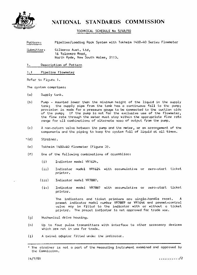
1. Description of Pattern
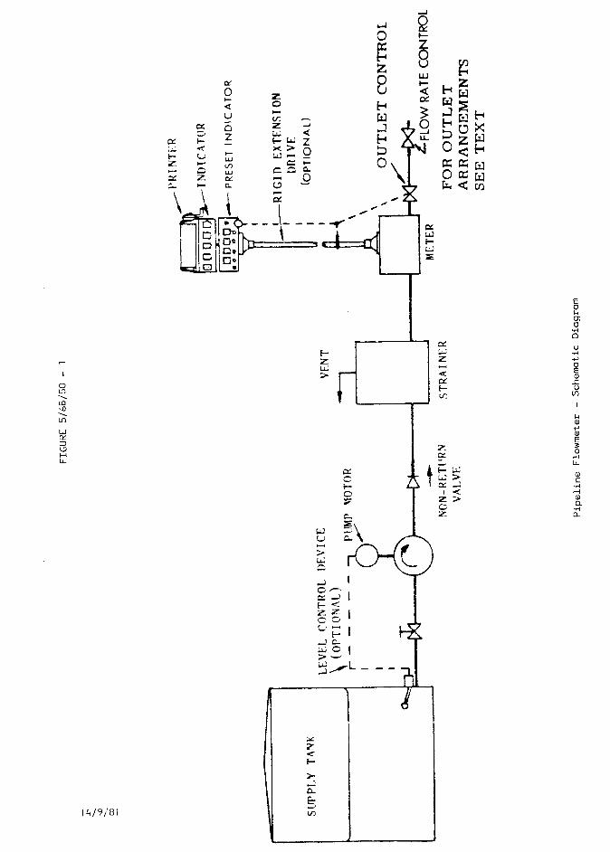
1 .l Pipeline flowmeter
Refer to Figure 1.
The system comprises:
(a) Supply tank.
(b) Pump - mounted lower than the minimum height of the liquid in the supply tank; the supply pipe from the tank has a continuous fall to the pump;
provision is made for a pressure gauge to be connected to the suction side of the pump; if the pump is not for the exclusive use of the flowmeter, the flow rate through the meter must stay within the appropriate flow rate range for all combinations of alternate uses of output from the pump,
(cl A non-return valve between the pump and the meter, or an arrangement of the
components ond the piping to keep the system full of liquid at all times.
*(d) Strainer.
(e) Tokheim 1400-40 flowmeter (Figure 3).
(f) One of the following combinations of assemblies:
(i) Indicator model VR1624.
(ii) Indicator model VR1624 with accumulative or zero-start ticket
printer.
(iii) Indicator model VR7887.
(iv) Indicator model VR7887 with accumulative or zero-start ticket
printer.
The indicators and ticket printers are single-handle reset. A
preset indicator model number VR7889 or VR1646 and preset-control valve may be fitted to the indicator with or without a ticket printer. The preset indicator is not approved for trade use.
(9) Mechanical drive housing.
(h) Up to four pulse transmitters with interface to other accessory devices which are not in use for trade.
(i) A swivel adaptor fitted under the indicator.
* The strainer is not a part of the measuring instrument examined and approved by the Commission.
1419181 .,..,...... /2
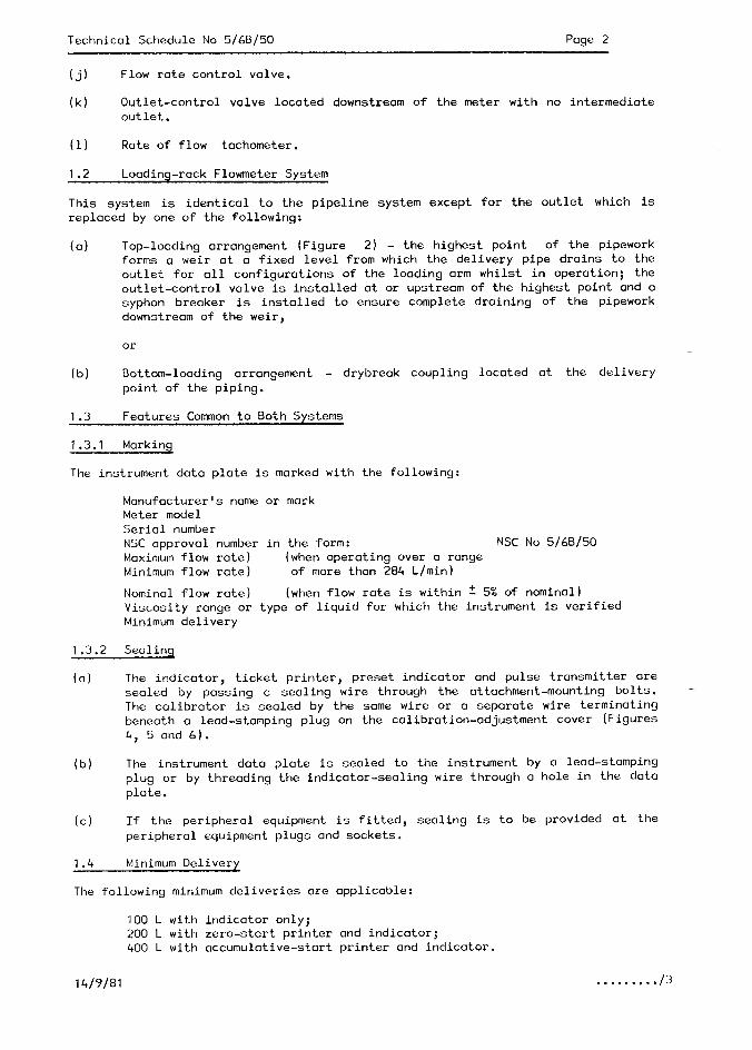
Technical Schedule No 5160150 Page 2
(j) Flow rate control valve.
(k) Outlet-control valve located downstream of the meter with no intermediate
outlet.
(1) Rate of flow tachometer.
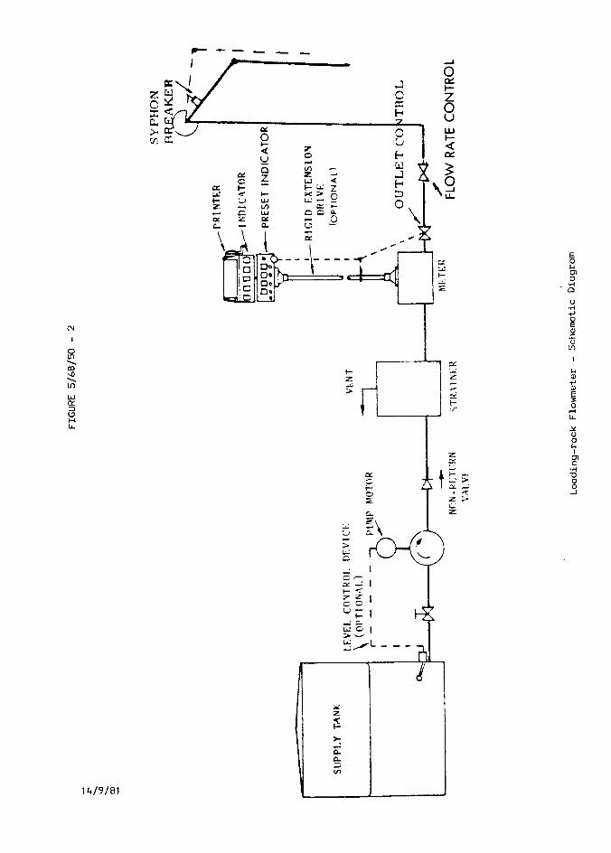
1.2 Loading-rack Flowmeter System
This system is identical to the pipeline system except for the outlet which is
replaced by one of the following:
(a) Top-loading arrangement (Figure 2) - the highest point of the pipework forms a weir at a fixed level from which the delivery pipe drains to the
outlet for all configurations of the loading arm whilst in operation; the
outlet-control valve is installed at or upstream of the highest point and a
syphon breaker is installed to ensure complete draining of the pipework downstream of the weir,
or
(b) Bottom-loading arrangement - drybreak coupling located at the delivery point of the piping.
1.3 Features Common to Both Systems
1.3.1 Marking
The instrument data plate is marked with the following:
Manufacturer’s name or mark Meter model Serial number NSC approval number in the form: NSC No 5/68/50
Maximum flow rate) (when operating over a range Minimum flow rate) of more than 284 L/min)
Nominal flow rate) (when flow rate is within t 5% of nominal)
Viscosity range or type of liquid for which the instrument is verified Minimum delivery
1.3.2 Sealing
(a) The indicator, ticket printer, preset indicator and pulse transmitter are sealed by passing o sealing wire through the attachment-mounting bolts. - The calibrator is sealed by the same wire or a separate wire terminating beneath a lead-stamping plug on the calibration-adjustment cover (Figures 4, 5 and 6).
(b) The instrument data plate is sealed to the instrument by a lead-stamping
plug or by threading the indicator-sealing wire through a hole in the data plate.
(cl If the peripheral equipment is fitted, sealing is to be provided at the
peripheral equipment plugs and sockets.
1.4 Minimum Delivery
The following minimum deliveries are applicable:
100 L with indicator only;
200 L with zero-start printer and indicator; 400 L with accumulative-start printer and indicator.
14/9/81 . . . , . . . . . I3
Techrlical Schedule No 5/60/50 Page 3
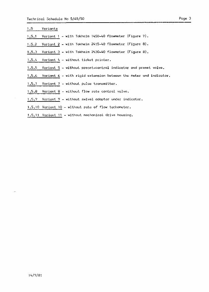
1.5 Variants
1.5.1 Variant 1
1.5.2 Variant 2
1.5.3 Variant 3
1.5.4 Variant 4
1.5.5 Variant 5
1.5.6 Variant 6
1.5.7 Variant 7
1.5.8 Variant 8
1.5.9 Variant 9
- with Tokheim 1450-40 flowmeter (Figure 7).
- with Tokheim 2415-40 flowmeter (Figure 8).
- with Tokheim 2430-40 flowmeter (Figure 8).
- without ticket printer,
- without preset-control indicator and preset valve.
- with rigid extension between the meter and indicator.
- without pulse transmitter.
- without flow rate control valve.
- without swivel adaptor under indicator.
1.5.10 Variant 10 - without rate of flow tachometer.
1.5.11 Variant 11 - without mechanical drive housing.
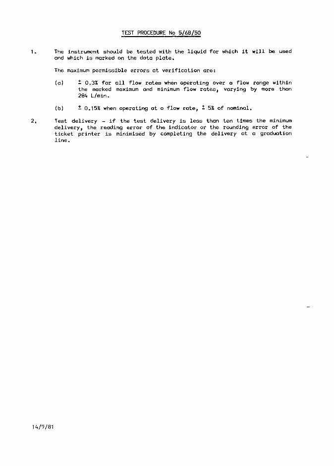
TEST PROCEDURE No 5/68/50
1. The instrument should be tested with the liquid for which it will be used
and which is marked on the data plate,
The maximum permissible errors at verification are:
(a) 2 0.3% for all flow rates when operating over a flow range within the marked moximum and minimum flow rates, varying by more than
284 L/min.
2.
(b) !: 0.15% when operating at a flow rate, * 5% of nominal.
Test delivery - if the test delivery is less than ten times the minimum
delivery, the reading error of the indicator or the rounding error of the
ticket printer is minimised by completing the delivery at a graduation line.
14/9/81
14191'81
14/9/81
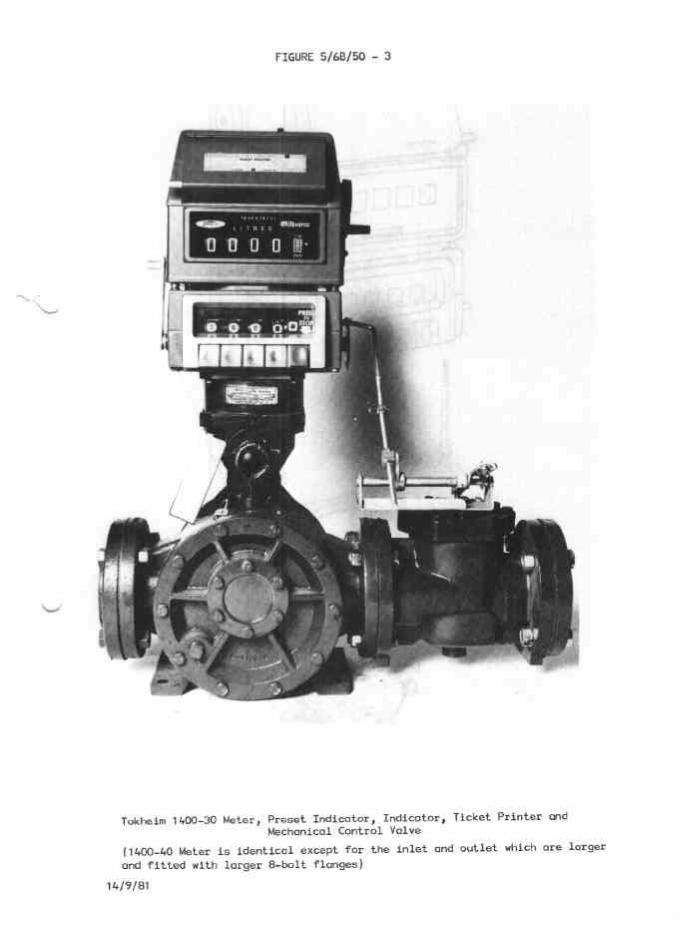
FIGURE 5/&B/M - 3
Tokheim ,&.~)-30 kter, preset Indicator, Indicator, Ticket printer ad Mechanical Control Valve
(140040 Meter is identical except for the inlet and outlet which OTT larger
and fitted with larger &bolt flanges)
14/V/81
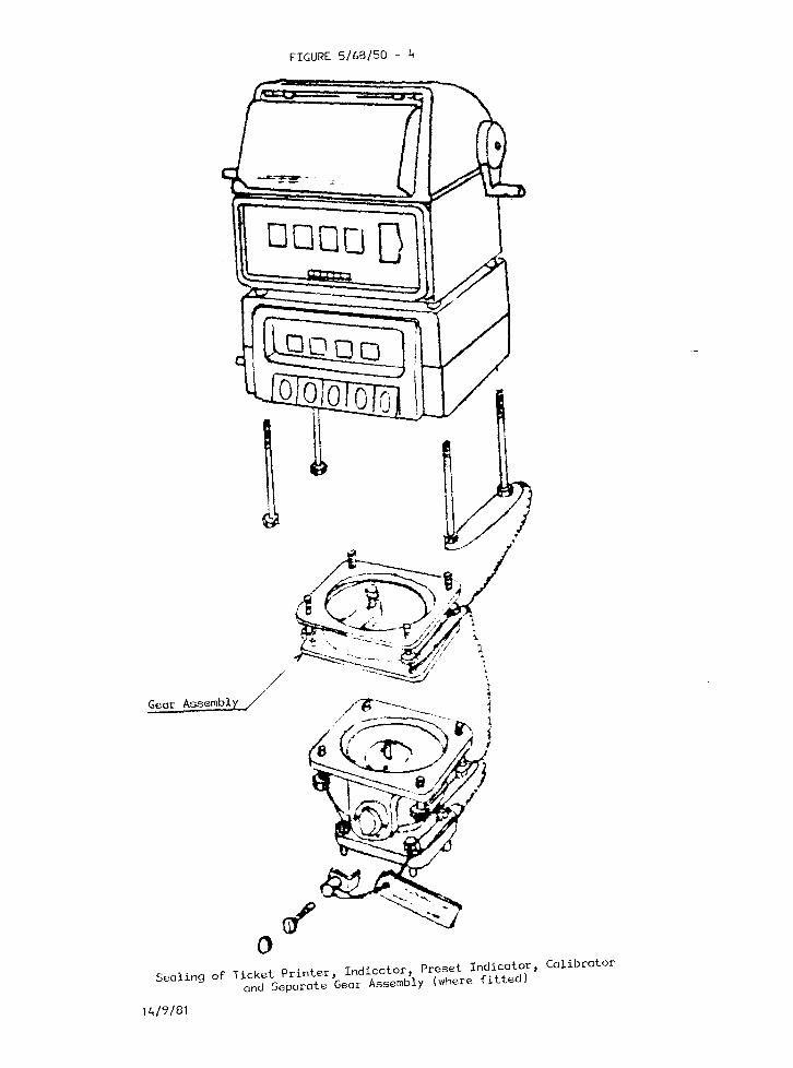
FIGURE 5/68/50 - 4
Gear Assembly/
Sealing of Ticket Printer, Indicator, Preset Indicator, Calibrator
and Separate Geor Assembly (where fitted)
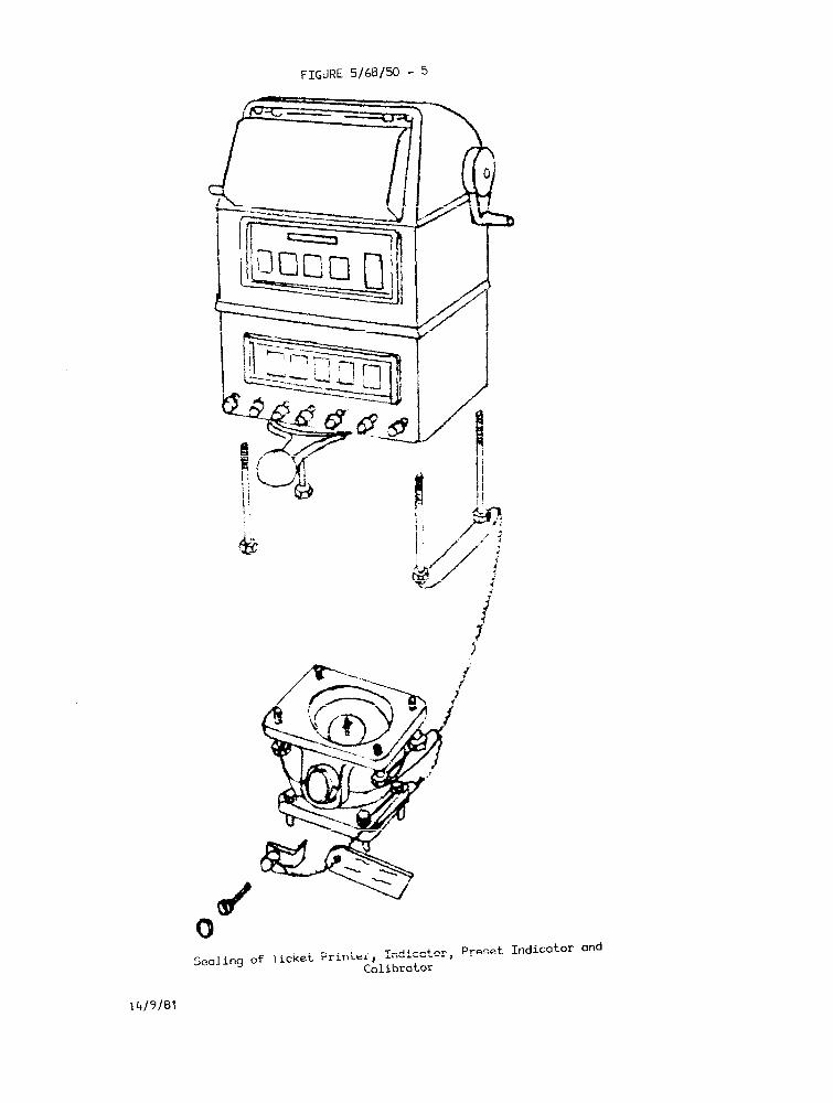
0 Sealing of Ticket Printer, Indicator,
Preset Indicator and
Calibrator
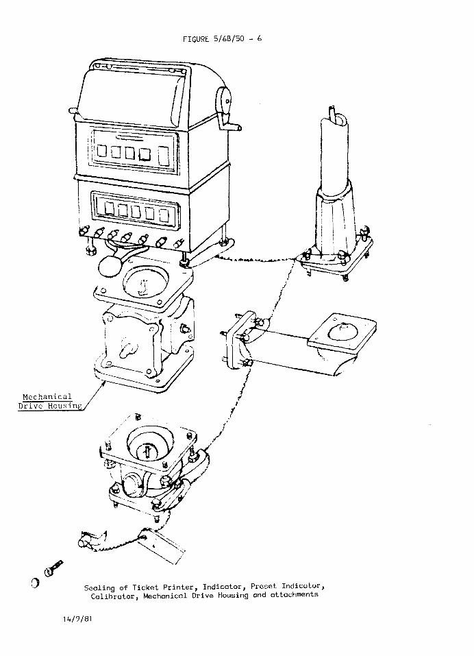
FIGURE 5/60/50 - 6
Sealing of Ticket Printer, Indicator, Preset Indicator, Calibrator, Mechanical Drive Housing and attachments
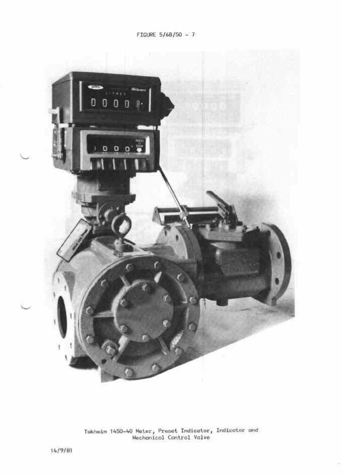
FIGURE 5/68/50 - 7
Tokheim ,4M-40 Meter, Preset Indicator, Indicator and Mechanical Control Valve
14/9/81
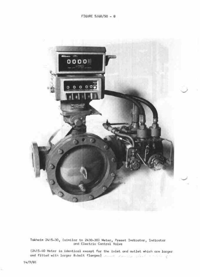
FIGURE 5/60/M - 8
Tokheim 241540, (similar to 2430-30) Meter, Preset Indicator, Indicator and Electric Control Valve
(241540 Meter is identical except fo'r the inlet and outlet which ore larger
and fitted with larger E-bolt flangesi A-- ' ,,,. . . : ,,
,4/9l01


![User's AXF Manual Magnetic Flowmeter Integral Flowmeter ... · Magnetic Flowmeter Integral Flowmeter/ Remote Flowtube [Hardware Edition] IM 01E20D01-01E IM 01E20D01-01E 7th Edition](https://img.dokumen.tips/doc/110x75/5e9c29fa54300501b21ae83a/users-axf-manual-magnetic-flowmeter-integral-flowmeter-magnetic-flowmeter-integral.jpg)


![User´s AXFA14G/C Manual Magnetic Flowmeter Remote ... · AXFA14G/C Magnetic Flowmeter Remote Converter [Hardware Edition/Software Edition] AXF Magnetic Flowmeter Integral Flowmeter](https://img.dokumen.tips/doc/110x75/5e9c29ae5a06915e2b2224e0/users-axfa14gc-manual-magnetic-flowmeter-remote-axfa14gc-magnetic-flowmeter.jpg)


![User's AXF Manual Magnetic Flowmeter Integral Flowmeter ... · User's Manual Yo kogawa Electric Corporation AXF Magnetic Flowmeter Integral Flowmeter/ Remote Flowtube [Hardware Edition]](https://img.dokumen.tips/doc/110x75/5c40f15893f3c338c3289cbb/users-axf-manual-magnetic-flowmeter-integral-flowmeter-users-manual-yo.jpg)


![AXR Two-wire Magnetic Flowmeter Integral Flowmeter [Style:S2]](https://img.dokumen.tips/doc/110x75/62cb14e07ee31d38b74d3e5b/axr-two-wire-magnetic-flowmeter-integral-flowmeter-styles2.jpg)

