Embed Size (px)
Citation preview
NATIONAL OPEN UNIVERSITY OF NIGERIA
SCHOOL OF SCIENCE AND TECHNOLOGY
COURSE CODE: PHY 124
COURSE TITLE: GEOMETRIC AND WAVE OPTICS
PHY 124 COURSE GUIDE
ii
PHY 124 GEOMETRIC AND WAVE OPTICS Course Developers/Writers Dr. Sanjay Goupta
National Open University of Nigeria Dr. C. O. Ajayi Physics Department
Ahmadu Bello University, Zaria. Programme Leader Dr. Sanjay Gupta National Open University of Nigeria
NATIONAL OPEN UNIVERSITY OF NIGERIA
COURSE GUIDE

PHY 124 COURSE GUIDE
iii
National Open University of Nigeria Headquarters 14/16 Ahmadu Bello Way Victoria Island Lagos Abuja Office No. 5 Dar es Salaam Street Off Aminu Kano Crescent Wuse II, Abuja Nigeria e-mail: [email protected] URL: www.nou.edu.ng Published by National Open University of Nigeria Printed 2008
Reprinted 2009 ISBN: 978-058-927-9 All Rights Reserved

PHY 124 COURSE GUIDE
iv
CONTENTS PAGE Introduction………………………………………………..………. 1 What You Will Learn in this Course………………………………... 1 Course Aims………………………………………………………… 2 Course Objectives……………………………….…………………… 2 Working through this Guide………………….……………………. 3 Course Materials………………………..………….………………. 3 Study Units……………………………..………………….……….. 4 Text Books and References……………………………….………. 4 Assignment File………………………………………….………... 5 Presentation Schedule……………………….…………….……….. 5 Assessment…………………….………………………….……….. 5 Tutor-Marked Assignment………………………………….……... 5 Final Examination and Grading…………………..………………... 6 Course Marking Scheme………………….……………………….. 6 Course Overview………………………………………...…………. 6 How to Get Most from the Course………..…………….…………. 7 Facilitators/Tutors and Tutorials……………………...……………. 9 Summary…………………………………..……………………….. 10

Introduction Light plays a vital role in human life. From the very beginning, it is a subject of great interest to know the secrets of light. We are always curious to know how we receive information to and from objects with the help of light. This is perhaps the reason to learn about the light and the phenomena associated with it. Geometric and wave optics is one semester 2 – Credits core course. It will be available to all students to take towards their B.Sc Education and other programmes like B.Sc computer science, environmental studies etc. This course comprises 15 study Units in 3 Modules, which involves basic principles of geometric and wave optics. The themes of these topics we have chosen are most interesting and relevant. The material for this subject has been developed in such a way that student with at least a credit pass at the ordinary level or equivalent will follow quite easily. This course will make the students to be aware of how perceive shapes, colors, motion of objects. There are no compulsory pre-requisites for the course. However, you are strongly advised to heave adequate knowledge for further Mathematics or applied mathematics. This course guide tells you briefly what the course is about, what course materials you will be using and how you can work your way through these materials. It suggests some general guidelines for the time you are likely to spend t complete it successfully. It also provides you guidance on tutor-marked assignments which will be available on the Web in due course. There are regular tutorials and practical classes that are linked to the course. You are advised to attend these sessions regularly as this is an important aspect. Details regarding the time and locations of tutorials and practical will be available at your Study Centre and included on Web. What You Will Learn in this Course The overall aim of PHY 124 is to introduce the basic principles of geometric and wave optics and appreciate the usefulness of these principles to make our life simpler and convenient. During this course, you will learn that light has a dual nature i.e. it exhibits characteristics of wave in some situations and characteristics of particle in other situations. In the beginning of this course, you would learn about reflection and refraction at plane and curved surfaces and the phenomena associated with them. Also, you learn about lenses and

PHY 124 GEOMETRIC AND WAVE OPTICS
ii
optical entrustments like telescopes, microscopes etc. required for scientific and technological developments. Towards the second part of this course, in the next few units, you will be introduced into some aspects of wave optics like interference and polarization of light. These include interference in thin films and air wedge, Newton’s rings, and laws ad application of polarization. Course Aims The aim of this course PHY 124: Geometric and wave optics is to introduce the principles of geometric and wave optics and so make use of these principles and their applications in everyday life. This will be achieved by: • Introducing you to the basic principles of geometric and wave
optics, • Demonstrating you how these basic principles can be used in our
day life situations, • Explaining some phenomena associated with geometric and wave
optics, • Stimulating your interest in this area for the betterments, of the
world through advancements of technology and, • Giving you some insight into possible future developments in the
areas of telecommunications optical lenses, optical instruments, surgery etc.
Course Objectives To achieve the aims set out above, the course sets over all objectives. In addition, each unit has specific objectives. The unit objectives are always included at the beginning of a unit; you should read them carefully before you start working through the unit. You may refer to them during your study of the unit to check your progress. You should always look at the unit objectives after completing a unit. In this way, you can be sure that you have done what was required of you for the unit. Mentioned below are the wider objectives of the course as a whole. By meeting these objectives, you should have achieved the aims of the course as a whole. On successful completion of the course, you should be able to: 1. Explain the concept of reflection and refraction;

PHY 124 GEOMETRIC AND WAVE OPTICS
iii
2. Explain how images are formed by reflection and refraction on plane and curved surfaces;
3. Apply the mirror formula to obtain either image distance or object distance or the focal length;
4. Define Snell’s law and how it can be related with refractive index or wavelength;
5. Describe refraction through a rectangular glass block and a prism; 6. Define a lens and identify its characteristics features; 7. Distinguish between the images formed by convex and concave
lenses; 8. Define and explain dispersion and identify the different colors of
white light; 9. Define power of a lens and to solve problems involving power of
a lens; 10. Explain the functions of microscope and astronomical telescope; 11. Distinguish between astronomical and terrestrial telescope; 12. Explain the concept of interference and the conditions for
interference; 13. Explain how a thin film and air wedge forms interference
patterns; 14. Differentiate between Newton’s rings and interference by him
films; 15. Identify the crystals that can produce polarize light; and 16. Define and explain Brewster’s law. Working through this Guide To complete this course you are required to go through the study units, read set books and read other materials provided by NOUN. You will also need to do some practical exercises, which will be arranged by your course facilitator/tutor. Each unit contains self-assessment exercises, and at points in the course you are required to submit assignments for assessment purposes. The evaluation of your TMAs will be done by the facilitator/tutor at the study center. At the end of the course, there is a final examination. The course shall take you about 15 weeks in total to complete. Below you will listed all the components of the course, what you have to do and how you should allocate your time to each unit in order to complete the course successfully and on time. Course Materials 1. Course Guide 2. Study Units 3. Assignment File 4. Presentation Schedule

PHY 124 GEOMETRIC AND WAVE OPTICS
iv
Study Units There are 15 Study Units in this course as follows: Module 1 Unit 1 Reflection at Plane Surfaces Unit 2 Reflection at Curved Surfaces Unit 3 Refraction at Plane Surfaces Unit 4 Refraction through Prism Unit 5 Refraction at Curved Surfaces Module 2 Unit 1 Images Formed by a Converging Lens and Diverging Lens Unit 2 Lens Formula and Spectra Unit 3 The Eye Unit 4 Optical instruments Unit 5 Other Types of Telescopes Module 3 Unit 1 Interference Unit 2 Interference in Thin Films and Air Wedge Unit 3 Newton’s Rings and Interference in Thin Films Unit 4 Polarization of Light Unit 5 Laws and Application of Polarization Each study unit consists of three hours work. Each study unit includes specific objectives, directions for study, reading materials, conclusions, summaries of key issues and ideas and references for further reading. The units direct you to work on exercises. In general, these self-assessment questions are based on the materials available in the units and will help you to gauge your progress and to reinforce your understanding of the material. Together with tutor-marked assignments, these exercises will assist you in achieving the stated learning objectives of the individual units and of the course. Text Books and References Nelkon and Parker, ‘An Advance Level Physics’, Published by British
Library Publication. Shortley and Williams, ‘Principles of College Physics’. Englcool Cliff
New Jersey: Prentice Hall Inc.:

PHY 124 GEOMETRIC AND WAVE OPTICS
v
Mark W. Zemansky, ‘College Physics’. London: Addision-Wasley. Waltham W. Ford, ‘Basic Physics’. London: Toronto. Kenneth W. Ford, ‘Basic Physics’. Toronto London: Wltham
Massachuesetts. Assignment File This assignment file will be supplied by NOUN. In this file, you will fine all the details of the work you must submit to your facilitator/tutor for marks that you obtain in your assignments will be counted in your final result you obtain for the course. Further information on assignments will be found in the assignment file itself and later in the Course Guide in the section on assessment. Therefore you are advised to take you assignments seriously and regularly. Before submitting, you must ensure that you have answered all the questions required from you in all assignments. There are about 15 assignments in this course. The assignments will cover all the topics treated in all the units. Presentation Schedule The presentation schedule included in your course materials gives you the important dates for the completion of tutor-marked assignments and attending tutorials. Remember, you have to complete the assignments in time and submit these stipulated assignments y the due date. Assessment There are two aspects to the assessment of you performance for the course. First are the tutor-marked assignments; second, there is a written examination, knowledge and techniques gathered during the course. The assignments must be submitted to your facilitator/tutor for formal assessments in accordance with the deadlines stated in the presentation schedule and the assignment file. The work you submit to your facilitator/tutor for assessment will carry 30% weightage of your total course work. At the end of your course, you need to appear for a final written examination of three hours duration. The final examination will carry 70% weightage of your course mark. Tutor-Marked Assignment The TMAs are listed as item 6.0 in each unit. The main of the assignments is to test your comprehension of the material provided to you and to help you by providing feedback to you. Generally, you will be able to complete your assignments from the information and
PHY 124 GEOMETRIC AND WAVE OPTICS
vi
materials contained in the study units of the course and other recommended books. Using other references will give you a broader viewpoint and provide a deeper understanding of the subject. On completion of each assignment, send it, together with a TMA form, to you facilitator/tutor. Make sure that each assignment reaches your facilitator/tutor on or before deadline mentioned by the course coordinator in the presentation schedule and assignment file. If, for any reason, you cannot complete you work on time, contact you facilitator/tutor before the assignment is due to discuss the possibility of an extension. Extensions will not be granted after the due date unless there are exceptional circumstances. Final Examination and Grading The final examination for PHY 124 will be of three hours duration and carry a weightage of 70% of the total course grade. The examination will consists of questions which reflect the type of self-testing practice exercises and tutor marked problems you have previously encountered. All areas of the course shall be assessed. Course Marking Scheme The assessment will be two folds – TMAs will carry 30% weightage of course marks while the final examination will carry 70% marks of the total marks obtainable. Course Overview The table given brings together the units, the number of weeks you should spend to complete them, and the assignments that follow them. Unit Title of Unit Week’s
Activity Assessment (end of unit)
Course Guide 0.5 Module 1
1 Reflection at Plane Surface 0.5 Assignment 1 2 Reflection at Curved
Surfaces 1.0 Assignment 2
3 Refraction at Plane Surfaces 1.0 Assignment 3 4 Refraction through Prisms 1.0 Assignment 4 5 Refraction at Curved
Surfaces 0.5 Assignment 5
6 Images Formed by Converging Lens and Diverging Lens
0.5 Assignment 6

PHY 124 GEOMETRIC AND WAVE OPTICS
vii
7 Lens Formula and Spectra 1.0 Assignment 7 8 The Eye 0.5 Assignment 8
9 Optical Instruments 1.0 Assignment 9 10 Other Types of Telescopes 1.0 Assignment 10 11 Interference 1.0 Assignment 11 12 Inference in Thin Films and
Air Wedge 0.5 Assignment 12
13 Newton’s Rings and Interference in Thin Films
1.0 Assignment 13
14 Polarization of Light 1.0 Assignment 14 15 Laws and Application of
Polarization 1.0 Assignment 15
Revision 2.0 Total 15.0 How to Get Most from the Course In distance learning, the study units replace the lecturer. This is one of the great advantages of distance learning; you can read and work through specially designed study materials at your own pace, and at a time and place that suit you best. Think of it as reading the lecture instead of listening a lecture. In the same way that a lecturer might set you some reading to do, the study units tell you when to read your set books or other materials, and when to undertake computing practical work. Just a lecturer might give you an in-class exercise, your study units provide exercises for you to do at appropriate points. Each of the study unit follows a common format. The first item is an introduction to the subject matter of the unit and how a particular unit is integrated with the other units and the course as a whole. Then, there is a set learning objectives. These objectives let you know what you should be able to do by the time you have completed the unit. You should use these objectives to guide your study. When you have finished the unit, you must go back and check whether you have achieved the objectives. If you make a habit of doing this, you will significantly improve your chances of passing the course. The main body of the unit guides you through the required reading from other sources. It will enhance your understanding of the material in the unit. Self-tests are interspersed throughout the units and answers are given within the units. Working through these tests will definitely help you to achieve the objectives of the unit and prepare you for the assignments and the examination. It is advised that you should do each self-tests as you come across in the study unit. There will also be numerous examples given in the study units; work through them when you come to them, too.

PHY 124 GEOMETRIC AND WAVE OPTICS
viii
The practical strategy for working through the course is mentioned below. If you have any trouble telephone your facilitator/tutor (or post the question on the Web CT OLE’s discussion board). Remember that facilitator/tutors are to help you. Here you will get an opportunity to discuss with them your problems pertaining to the course of your study. So, when you need help, don’t hesitate to consult you facilitator/tutor to provide it. 1. First of all, read the Course Guide carefully and thoroughly. 2. Then, organize a study schedule. Refer to the course overview for
more details. Note the time you are expected spend on each unit and how the assignments relate to the units. Important information’s regarding the details of your tutorials and the date of the first day of the semester is available from the Web ct OLE. You need to gather all the informations in one lace, such as your diary or a wall calendar. Whatever method you choose to use, you should decide on and write in you own dates for working on each unit.
3. Once you have created your own study schedule, do everything
you can to stick to it. The major reason that student fail is that they get behind their course work. If you have any difficulty with your schedule, please let your facilitator/tutor know before it is too late for help.
4. Turn to unit 1 and read the introduction and the objective for the
unit. Assemble the study materials. You will almost always both the study unit you are working on and of your set books on your desk at the same time.
5. Work through the unit. The content of the unit itself has been
arranged to provide a sequence for you to follow. As you work through the unit, you will be instructed to read section of your set books or other articles. Use the unit objectives to guide your readings.
6. Update yourself on the Web CT OLE. Up-to-date information
will be continuously posted there. 7. Keep in mind that you will learn a lot by doing the assignments
carefully. The assignments have been designed to help you to meet the objectives of the course and, therefore, will help you pass exam. Submit all assignments y due date.
PHY 124 GEOMETRIC AND WAVE OPTICS
ix
8. Review the objectives for each study unit to confirm that you have achieved them. If you feel unsure about any of the objectives, review the study materials or consult your facilitator/tutor. After ensuring that you have achieved a unit’s objectives, then start on the next unit. Proceed unitwise through the course and try to keep yourself on schedule.
9. When you have submitted an assignment to your facilitator/tutor
for marking, do not wait for its return before starting on the next unit. The evaluated assignments will be returned to you with tutor comments and marks obtained in TMAs. Keep to your schedule. When the assignment is returned, pay particular attention to your tutor’s comments, both on the tutor-marked assignment form and also written on the assignments. Consult your facilitator/tutor as soon as possible if you have any question or problems.
10. After completing the last unit, give sometime to review the
course and prepare yourself for the final examination. Check that you have achieved the unit objectives listed at the beginning of each unit and the course objective listed in the course Guide.
Facilitators/Tutors and Tutorials There are 5 hours of tutorials provided in support of this course. You will be notified of the dates, time and location of these tutorials, together with the name and phone number of your facilitator/tutor, as soon as you re allocated a tutorial group. Your facilitator/tutor will evaluate and comment on your assignments, keep a close watch on your progress and on any difficulties you might face and provide assistance to you during the course. You must mail your tutor-marked assignments to your facilitator/tutor well before the due date (at least two working days required). They will be marked by your facilitator/tutor and returned to you with comments at he earliest. Do not hesitate to contact your facilitator/tutor by telephone, email, or discussion board if you need help. The following might be circumstances in which you would find help necessary. Contact your facilitator/tutor if: • If you do not understand any part of the study units or the
assigned readings. • You have the difficulty with the self-tests or exercises.

PHY 124 GEOMETRIC AND WAVE OPTICS
x
• You have a question or problem with an assignment, with your tutor’s comments on an assignment or with the grading of an assignment.
You should try your best to attend the tutorials. This is the only chance to have face to face contact with your tutor and to ask questions which are answered instantly. You can raise any problem encountered in the course of your study. To gain the maximum benefit from course tutorials, prepare a question list before attending them. You will learn a lot from participating in discussion actively. Summary PHY 124 intends to introduce basic principles and applications of Geometric and wave optics. Upon completing this course, you will be equipped with knowledge of reflection, refraction, interference, polarization and dispersion etc. and the laws and phenomena associated with them. Also will learn how geometric and ray optics is useful in our day-to-day life. You will be able to answer these kinds of questions: 1. What is reflection and refraction? 2. How reflection occurs at plane and curved surfaces? 3. How total internal reflection is useful for us? 4. How we see the different colours when a ray of white light passes
through prism? 5. What is a power of a lens? 6. How lens maker’s law can apply? 7. What are the various parts of the eye? 8. How the microscope and telescope functions? 9. Is the astronomical telescope different from terrestrial telescope? 10. What are coherent sources? 11. How air wedge forms interference patterns? 12. What is the difference between Newton’s rings and interference
by thin films? 13. What are the ways to produce a polarized light 14. What is Brewster’s law? 15. What are the applications of polarized light?

PHY 124 GEOMETRIC AND WAVE OPTICS
xi
Course Code PHY 124 Course Title Geometric and Wave Optics Course Developers/Writers Dr. Sanjay Goupta
National Open University of Nigeria Dr. C. O. Ajayi Physics Department
Ahmadu Bello University, Zaria. Programme Leader Dr. Sanjay Gupta National Open University of Nigeria
NATIONAL OPEN UNIVERSITY OF NIGERIA

PHY 124 GEOMETRIC AND WAVE OPTICS
xii
National Open University of Nigeria Headquarters 14/16 Ahmadu Bello Way Victoria Island Lagos Abuja Office No. 5 Dar es Salaam Street Off Aminu Kano Crescent Wuse II, Abuja Nigeria e-mail: [email protected] URL: www.nou.edu.ng Published by National Open University of Nigeria Printed 2008
Reprinted 2009 ISBN: 978-058-927-9 All Rights Reserved

PHY 124 GEOMETRIC AND WAVE OPTICS
xiii
CONTENTS PAGE Module 1 Reflection and Refraction at Plane and Curved
Surfaces……………………………….…….……... 1 Unit 1 Reflection at Plane Surfaces……………….………… 1 Unit 2 Reflection at Curved Surfaces…………………..……. 8 Unit 3 Refraction at Plane Surfaces………………….……… 20 Unit 4 Refraction through Prisms…………….…………….. 31 Unit 5 Refraction at Curved Surfaces……………………….. 40 Module 2 Lenses and Optical Instruments…………..……..… 47 Unit 1 Images Formed By a Converging Lens and Diverging
Lens (Ray Tracing)……………………………..…… 47 Unit 2 Lens Formula and Spectra……….………………….. 56 Unit 3 The Eye……………………………..……………….. 70 Unit 4 Optical Instruments……………………..…………… 79 Unit 5 Other Types of Telescopes…………………………… 90 Module 3 Interference and Polarization of Light………….…. 98 Unit 1 Interference……………………….………………….. 98 Unit 2 Interference in Thin Films and Air Wedge…............... 111 Unit 3 Newton’s Rings and Interference in Thin Films…….… 118 Unit 4 Polarization of Light………………………….……... 129 Unit 5 Laws and Application of Polarization………….…… 136

PHY 124 GEOMETRIC AND WAVE OPTICS
1
MODULE 1 REFLECTION AND REFRACTION AT PLANE AND CURVED SURFACES
Unit 1 Reflection at Plane Surfaces Unit 2 reflection at Curved Surfaces Unit 3 refraction at Plane Surfaces Unit 4 refraction Through Prisms Unit 5 refraction at Curved Surfaces UNIT 1 REFLECTION AT PLANE SURFACES CONTENTS 1.0 Introduction 2.0 Objectives 3.0 Main Contents
3.1 Laws of Reflection 3.2 Reflection at Plane Surfaces 3.3 Image Formed by Plane Mirror
4.0 Conclusion 5.0 Summary 6.0 Tutor-Marked Assignment 7.0 References/Further Readings 1.0 INTRODUCTION We see objects either by the light they produce or by the light they reflect from other objects. Objects that produce their own light are said to be luminous. Examples are the sun, candle light, electric light bulbs etc. Whereas, non-luminous objects do not produce their own light. They are seen only when light from other sources fall on them and is thrown back or “reflected” into our eyes. For example the moon shines in the night because it reflects light coming from the sun and not because it is luminous. i) The narrowest of light is a ray which is usually diagrammatically
represented by a thin line (as shown in Fig. 1.1a) with an arrow head on it. The arrow head represents the direction of propagation of the light.
ii) A group of rays gives rise to a beam of which can be parallel or convergent or divergent as shown in Fig. 1.1. Light rays can be reflected or refracted on plane or curved surfaces depending on the nature of the surfaces, including their material make up. In this unit we shall only look at reflection of light by a plane surface.

PHY 124 GEOMETRIC AND WAVE OPTICS
2
Fig. 1.1: A ray and type of beams of light.
2.0 OBJECTIVES
After studying this unit, you will be able to: • recognize incident and reflected rays • recognize angle of incident and angle of refraction • explain how images are formed by plane mirrors • solve problems related to reflection at plane surfaces • state the laws of reflection • experimentally verify the laws of reflection. 3.0 MAIN CONTENT 3.1 Laws of Reflection
Fig.1.2: Reflection from a surface of a plane mirror
In this Fig 1.2, i is the angle of incident and r is the angle of reflection. Fig. 1.2 shows a ray of light AB which is incident on the surface of a plane mirror at an angle of incident i from the normal to the mirror. BC is the ray of light reflected from the surface of the mirror, therefore is known as the reflected ray. The angle formed by the reflected ray with normal is r called angle of reflection. As it can be seen from Fig.1.2, the incident ray, the reflected ray and the normal to the mirror at the point of incidence all lie in the same plane. This is the first law of reflection.
(a) A light ray (b) Parallel beams (c) Divergent beams (d) Convergent beams
N
Normal
Reflected ray
Incident ray
i r
B
A C

PHY 124 GEOMETRIC AND WAVE OPTICS
3
Also, it has been experimentally found that angle i = angle r …..(1.1) That is, Eq. 1.1 implies that the angle of incident is always equal to the angle of reflection. This has given rise to what is known as second law of reflection. Consequently the laws of reflection can be summarized as follows: 1st Law The incident ray, the reflected ray and the normal at the point of incidence all lie in the same plane. 2nd Law The angle of incident equals the angle of reflection. 3.2 Reflection at Plane Surfaces When light is reflected from a surface that is smooth or polished it may act as a mirror and produce a reflected image. If the mirror is flat, or plane, the image of the object appears to lie behind the mirror at a distance equal to the distance between the object and the surface of the mirror. In figure 1.3, the light source is the object A, and the point on A sends out rays in all directions. The two rays that strike the mirror at B and C, are reflected as the rays BD and CE. To an observer in front of the mirror, these rays appear to come from the point F behind.
Fig. 1.3: Formation of an image by a plane mirror
Observer D
B
C
F A
Light Source
E
Mirror Image

PHY 124 GEOMETRIC AND WAVE OPTICS
4
Formation of Image by Plane Mirror In the mirror, it follows from the laws of reflection that CF and BF form the same angle with the surface of the mirror, as do AC and AB. If the surface of reflection is rough, then normal to various points of the surface lie in random directions in that case, rays that may lie in the same plane when they emerge from a point source nevertheless lie in random planes of incidence and therefore of reflection, and are scattered and can not form an image. 3.3 Image Formed by Plane Mirror A real image is the one formed through actual intersection of light rays, and can be captured on a screen.
Fig. 1.3 (a): A real image A virtual image is that formed by imaginary intersection of light rays and can not be formed or captured on the screen. Virtual image I
Fig. 1.4 (b): Virtual image SELF ASSESSMENT EXERCISE 1 Look at yourself in a mirror and compare your image with yourself and answer the following questions. 1. Is your image real or virtual?
I
Imaginary intersection

PHY 124 GEOMETRIC AND WAVE OPTICS
5
2. What can you deduce about the way or direction your image is pointing?
3. Is your head in your image and in real life pointing in the same direction?
4. On which side of your body (real) does your right side in the image appear to be?
5. Is your image of the same size as your physical body? 6. Finally, what can you deduce from 1-5 above? Having gone through exercise 1.1 above, you must have some idea about the plane mirrors and the formation of images in plane mirrors. Now, we will discuss the characteristics of images formed by a plane mirror. Major Characteristics of images formed by plane mirror are as follows: i) It is upright, that is, the image is oriented in the same direction as
the object. ii) It is virtual, that is, it can not be received on the screen. iii) It is of the same size as the object. iv) It is laterally inverted. 4.0 CONCLUSION Any polished surface is capable of becoming a reflector of light. Where a reflection occurs, the incident ray, the reflected ray and the normal all lie in the same plane. Also the angle of incident, i, is equal the angle of reflection r. These two laws constitute the laws of reflection. Finally, the formation of an image by a mirror is an application of reflection of light at a plane surface. 5.0 SUMMARY • A ray is a fundamental component of light in a given direction
and is represented by a thin line with an arrow, while a beam of light consists of several rays.
• A beam can be parallel, convergent or divergent. • A beam or a ray of light incident on a polished surface at an angle
i which is not 900 is reflected at angle r from the surface, while angle i ( angle of incident) = angle r (angle of reflection).
• There are two laws of reflection: 1st Law: The incident ray, the reflected ray and the normal at the point of incidence all lie in the same plane. 2nd Law: The angle of incident is equal to the angle of reflection.

PHY 124 GEOMETRIC AND WAVE OPTICS
6
• The image formed by a plane mirror due to reflection of light by the plane mirror is such that the distance of the mirror object from the surface of the mirror and the distance of the image from the surface of the mirror are equal.
6.0 TUTOR-MARKED ASSIGNMENT Activity Place or fix a sheet of white A4 size paper with a thumbtack at each edge of the paper. With the help of two empty match boxes with vertical slot (holes) cut into them, support the mirror in a vertical position on the paper as shown in Fig. 1.5 below. Q
Fig. 1.5: A mirror in a vertical position on a paper Then, trace with your pencil the surface of the mirror, line AB on the paper. Place a point P and place another one as point Q as shown in fig. 1.5. Move your head to the left of P, looking into the mirror as you move your head, until you see the image of P in line with P appearing to be along line P′Q. Use a third pin R to a line with P′ and Q. That is, until when pins P′, Q and R appear to be on the same straight line. When this occurs, fix pin R on the paper and remove the mirror. Then, draw line M Q such that line M Q is 90o to line AB. Measure the angle between MQ and PQ and then, the angle between MQ and QR. Questions 1. What is line MQ called? 2. What is line PQ called? 3. What is line QR called? 4. What is angle PQM called and what is angle MQR called? 5. What can you deduce about the magnitude of angle PQR and
MQR? 6. From 1-5, deduce the laws of reflection.
B
A Match box
Match box
Mirror
R
M
P
P′

PHY 124 GEOMETRIC AND WAVE OPTICS
7
7.0 REFERENCES/FURTHER READINGS Nelkon and Parker. Advance Level Physics. British Library Publication. Kenneth .W. Ford. Basic Physics. Toronto London: Waltham
Massachusetts. Mark .W. Zemansky. College Physics. London: Addison – Wesley. Shortley and Williams. Principles of College Physics. Englewood Cliff
New Jersey: Prentice Hall Inc.
PHY 124 GEOMETRIC AND WAVE OPTICS
8
UNIT 2 REFLECTION AT CURVED SURFACES CONTENTS 1.0 Introduction 2.0 Objectives 3.0 Main Content
3.1 Images Formed by Curved Mirrors 3.1.1 Images Formed by a Concave Mirror when the
Object is Placed Beyond Center of Curvature 3.1.2 Image Formed by a Concave Mirror when the
Object is Placed between the Center of Curvature and the Principal Focus
3.1.3 Image Formed by a Concave Mirror when the Object is Placed before the Principal Focus
3.2 The Mirror Formula 4.0 Conclusion 5.0 Summary 6.0 Tutor-Marked Assignment 7.0 References/Further Readings 1.0 INTRODUCTION In the last Unit, you studied reflections at plane (flat) surfaces. In this unit you will study reflection at curved surfaces. Such surfaces include concave and convex mirrors. When light is incident on a curved surface of mirror, the reflected rays either diverge or converge depending on the direction of curvature of the surface. We could produce a curved surface by cutting out a part of a hollow spherical shell. A concave mirror is a curved surface which is silvered inside while a convex mirror is a curved surface that is silvered side is outside, as shown in Fig. 2.1 (a) and 2.1 (b) respectively. Therefore, a concave or converging mirror reflect light from its inside while a convex or diverging mirror reflect light from its outside as shown in Fig. 2.2 (a) and Fig. 2.2 (b).

PHY 124 GEOMETRIC AND WAVE OPTICS
9
Reflective Reflective Silvered Side Side Silvered Side Side
Fig. 2.1 (a) concave mirror (b) convex mirror
Fig. 2.2 (a) Fig. 2.2 (b) Because the convex mirror or the concave mirror is part of a sphere, it has a center C called the center of curvature, and a radius (r) called radius of curvature. And it also has a Principal Focus F1, whose distance from the pole P to the mirror is half the radius of curvature. These parameters are shown in Fig. 2.2 for the convex mirror respectively. 2.0 OBJECTIVES After studying this unit, you will be able to: • distinguish between reflection at curved surface and that at a
plane surface • identify the principal focus of a curved mirror • obtain images formed by a curved mirror using ray diagrams • state the mirror formula • apply the mirror formula to obtain either image distance or object
distance or the focal length and solve problems involving a curved mirror
• define magnification.
Principal axis
C F P
A

PHY 124 GEOMETRIC AND WAVE OPTICS
10
3.0 MAIN CONTENT 3.1 Images Formed by Curved Mirrors We can find the nature and position of the images formed by curved mirrors with the help of ray diagrams drawn to scale. To do this, we make use of the following facts: i) A ray parallel to the principal axis passes through the principal
focus after reflection (refer Fig. 2.3 (a)) ii) A ray through the center of curvature is reflected back along its
path (refer Fig. 2.3(b)). iii) As a corollary to (i), any ray through the principal focus is
reflected parallel to the principal axis (refer Fig. 2.3 (c)). The points to which these reflected rays converge or from which they appear to diverge represent the required image. In practice however, the tracing of only two of these rays will enable us to find the position of the image.
Fig. 2.3(a): Ray parallel to principal axis reflects back through principal focus F.
Fig. 2.3 (b): A ray goes through centre of curvature reflected back along its path
Principal axis
A
C F P
A
O
A
C F P
O

PHY 124 GEOMETRIC AND WAVE OPTICS
11
Fig. 2.3(c): A ray goes through principal focus F reflected back parallel to the principal axis.
We can represent the object as a straight line perpendicular to the principal axis with arrow to represent its head. Now, in the next sub-sections, with the help of diagrams, we will show the position and nature of the image produced by a concave mirror using these facts.
3.1.1 Image Formed by a Concave Mirror When the Object is Placed Beyond Centre of Curvature
Fig. 2.4 shows the ray diagram for the Image formed by a concave mirror when the object is placed beyond the center of curvature and OP represents the object, IQ represents the image. F and C respectively represent the Principal focus and the center of the curvature of the mirror. I
Fig 2.4: Image formed by a concave mirror for object before C.
The figure shows that the image formed is inverted (that is, in opposite direction to the object). The image is also diminished (that is, smaller than the object) and it occurs to the right of the center of curvature C. Finally, the image is real, because it can be received on the screen.
A
C F P O
O
P
C Q
F
u
v f
r
Concave mirror

PHY 124 GEOMETRIC AND WAVE OPTICS
12
3.1.2 Image Formed by a Concave Mirror when the Object is Placed between the Center of Curvature C and the Principal Focus F
Fig. 2.5 shows the ray diagram for the image formed by a concave mirror when the object is placed between the center of curvature C and the principal focus F.
Fig. 2.5: Image formed by a concave mirror for an object between C and F.
The figure suggests that the image formed by the concave mirror has the following characteristics: i) it is real; ii) it is magnified, that is, larger than the object; iii) it occurs after C (to the left of C); and iv) it is inverted. 3.1.3 Image Formed by a Concave Mirror when the Object is
between the Principal Focus F and the Mirror Fig. 2.6 shows the ray diagram of the image formed by the concave mirror when the object lies between the mirror and the principal focus F.
Q
I
C O F
P

PHY 124 GEOMETRIC AND WAVE OPTICS
13
Fig. 2.6: Image formed by a concave mirror for object between F and the mirror.
The figure suggests that the image formed is behind the mirrors. Therefore, it is virtual because it cannot be received on the screen. 3.2 The Mirror Formula As you have learnt in section 3.1.1, that the distance of the object from the mirror is known as object distance. This is usually represented by letter u. Similarly, the distance between image and mirror is known as the image distance, this is generally represented by letter v, also one may not need to determine u or v by construction as done in section 3.1 because it has been experimentally found, that there is mathematical relationship connecting these parameters (without proof). The mathematical relationship is given as:
fuv
111 =+ ….. (2.1)
Where f is the focal length. Magnification In the day to day language, magnification is the degree of enlargement or reduction of the size of an object through it image formed. Magnification is mathematically represented by M. M = Height of image Height of object
C F I
Q

PHY 124 GEOMETRIC AND WAVE OPTICS
14
This can also be represented in terms of image distance of the mirror v and object distance u from the mirror. Mathematically it can be expressed as:
M = Image distance Object distance
i.e. M = u
v …..(2.2)
A “real” image is considered as having positive value, whereas a “virtual” image is considered as having negative value. This convention is normally borne in mind in the application of the mirror formula. This means that distances for real objects and images are considered as positive while distance for virtual objects or images are considered to be negative. Also, the focal length for a concave mirror is normally considered as positive while that of a convex mirror is considered as negative value.
Now we will quickly solve few examples to clear these concepts of mirror formula and magnification.
Example 2.1 An object is placed 0.15 m in front of a concave mirror of focal length 0.1m. Determine the position, nature and magnification of the image formed. Solution: Object position u = 0.15 m Focal length f = 0.1 m The focal length is positive
because the mirror is concave To determining the position of the image ( image distance), we apply the mirror formula. The mirror formula is given as
vuf
111 +=
ufv
111 +=∴
3
10
15
1001501 =−=v
mv 3.010
3 ==⇒
PHY 124 GEOMETRIC AND WAVE OPTICS
15
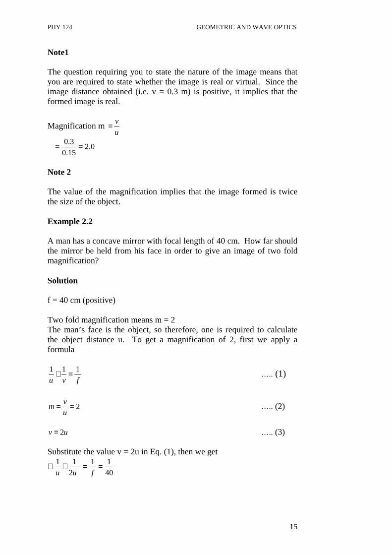
Note1 The question requiring you to state the nature of the image means that you are required to state whether the image is real or virtual. Since the image distance obtained (i.e. v = 0.3 m) is positive, it implies that the formed image is real.
Magnification m u
v=
0.215.0
3.0 ==
Note 2 The value of the magnification implies that the image formed is twice the size of the object. Example 2.2 A man has a concave mirror with focal length of 40 cm. How far should the mirror be held from his face in order to give an image of two fold magnification? Solution f = 40 cm (positive) Two fold magnification means m = 2 The man’s face is the object, so therefore, one is required to calculate the object distance u. To get a magnification of 2, first we apply a formula
fvu
111 =+ ….. (1)
2==u
vm ….. (2)
uv 2= ….. (3)
Substitute the value v = 2u in Eq. (1), then we get
40
11
2
11 ==+∴fuu

PHY 124 GEOMETRIC AND WAVE OPTICS
16
40
1
2
12 =+u
1202
40
1
2
3
=⇒
=
u
u
cmu 60=
- - - - - - - - - - - - - - - - - - - - - - - - - - - - - - - - - - - - - - - - - - - - - - - - - - CONVEX MIRROR
Fig. 2.7: Formation of an image by convex mirror Fig. 2.7 shows the ray diagram for the formation of an image by a convex mirror. OP is the object and IQ is the image. As usual, the ray PA which is parallel to the principal axis of the mirror, is reflected from the surface of the mirror at A as if it is coming from F. Also, the ray PB that is directed from the top of the object towards the center of curvature (C) of the mirror is reflected back along the same path as if it is coming from C. Thus, the intersection of the two rays (dotted lines in the figure) gives rise to formation of image IQ. Fig. 2.7 shows that the image formed by the convex mirror is i) Upright ii) Formed behind the mirror; therefore it is virtual; iii) Diminished, that is, smaller than the object. It is necessary to note that the characteristics of the image stated above are true for the convex mirror, irrespective of where the object is placed in the front of the mirror. Thus, convex mirror is said to have a very wide field of view. Hence, because the image formed by the convex mirror is erect, the convex mirror is always use in motor vehicle as side mirror.
Q
O
P
I F C Pole
B A

PHY 124 GEOMETRIC AND WAVE OPTICS
17
Example 2.3 A diverging mirror of 50.0 cm focal length produces a virtual image of 25.0 cm from the mirror. How far from the mirror should the object be placed? Solution A diverging mirror is a convex mirror, and therefore, its focal length is negative i.e. f = -50.0 cm. Similarly, since the image is virtual it implies that v = - 25.0 cm. From the problem, it is required to calculate the object distance u. ∴Using the mirror formula
fvu
111 =+
On rearranging the terms, we get
vfu
111 −=
Substituting the values of v and f into the above Eq., we get
)0.25(
1
0.50
11
−−
−=
u
50
1
50
211 =+−=u
cmu 0.50=
4.0 CONCLUSION The curved mirror either concave or convex is part of a hollow sphere. When the sphere is silvered inside it is a concave mirror while it is convex if it is silvered outside. That is, a convex mirror reflect light from its outside whereas a concave mirror reflects light from its inside. Both or either the concave or convex mirror has center of curvature C, Principal Focus F, the principal axis and a pole. Because the convex mirror diverges parallel rays of light, it is called a divergent mirror, whereas the concave mirror is called a convergent mirror, because it converges parallel rays of light. The image formed by

PHY 124 GEOMETRIC AND WAVE OPTICS
18
either a convex mirror or a concave mirror can be determined using either the ray diagram or the mirror formula. For the same reason, the basic facts used are as follows: i) a ray of light parallel to the axis of the mirror is reflected by the
mirror through the principal focus; ii) a ray of light directed to the center of curvature of the mirror is
reflected back along the same path; iii) a ray of light incident on the mirror through a Principal Focus is
reflected parallel to the axis of the mirror. In using the mirror equation the following sign convections are used: i) real objects and images have positive distances; ii) virtual objects and images have negative distances; iii) Concave mirrors have positive focal length and radii of curvature
while convex mirrors have negative focal length and radii of curvature.
5.0 SUMMARY • Curved mirrors, concave or convex, are part of hollow spheres. • The reflecting surface of a concave mirror is inside while that of
a convex mirror is outside. • A concave mirror or convex mirror has a pole, center of curvature
and the principal focus. • The focal length of concave mirror is considered positive while
that of the convex mirror is taken as negative. • A concave mirror can form a real or a virtual image, depending
on the location of the object. On the other hand, the convex mirror forms an erect and virtual image irrespective of where the object is located.
• A concave mirror can form either an enlarged or a diminished image depending on the position of the object.
• As a result, the convex mirrors have a wide field of view and always form an erect image. It is used as rear view mirrors in automobiles.

PHY 124 GEOMETRIC AND WAVE OPTICS
19
6.0 TUTOR-MARKED ASSIGNMENT A pin 2 cm long is placed 25 cm away from the pole of a concave mirror of focal length 10 cm. Determine its magnification. 7.0 REFERENCE/FURTHER READINGS Nelkon and Parker. Advance Level Physics. British Library Publication. Kenneth .W. Ford. Basic Physics. Toronto London: Waltham
Massachusetts. Mark .W. Zemansky. College Physics. London: Addison – Wesley. Shortley and Williams. Principles of College Physics. Englewood Cliff
New Jersey: Prentice Hall Inc.
2 cm 10 cm
25
F C P

PHY 124 GEOMETRIC AND WAVE OPTICS
20
UNIT 3 REFRACTION AT PLANE SURFACES CONTENTS 1.0 Introduction 2.0 Objectives 3.0 Main Content
3.1 Refraction at Plane Surfaces 3.1.1 The Bending of Ray of Light when it Travels from
Air to Water 3.1.2 The Bending of Ray of Light when it Travels from
Water to Air 3.2 Laws of Refraction
3.2.1 Snell’s law 3.2.2 Refractive Index 3.2.3 Critical Angle
3.3 Total Internal Reflection 3.3.1 Application of Total Internal Reflection
4.0 Conclusion 5.0 Summary 6.0 Tutor-Marked Assignment 7.0 References/Further Readings 1.0 INTRODUCTION Light plays a vital role in our life. This is the only mean by which one can see the objects. From the very beginning, efforts were made to explain many properties of light. Then phenomena of reflection and refraction were explained by Newton. Later Huygens explained the phenomena of reflection and refraction by using wave theory of light. In this unit, we will not discuss the wave theory of light. In the earlier two units, you have learnt about reflection at plane and curved surfaces respectively. But in this unit, you will learn the refraction of light that occurs when light travels from one medium to another medium through a boundary. When a ray enters to the second medium, it bent at the boundary. This bending of a ray of light from the boundary is known as refraction. Before proceeding further for the laws of refraction and total internal reflection in this unit, it is important to know about the concepts of refractive index and critical angle. So here, we will briefly discuss about these concepts.

PHY 124 GEOMETRIC AND WAVE OPTICS
21
2.0 OBJECTIVES After studying this unit, you will be able to: • distinguish between rare medium and denser medium • know about the concept of refraction • explain how the refraction takes place from one medium to
another • explain the meaning of refractive index • state Snell’s law • define Critical angle • state the laws of refraction • set up a relation between refractive index and wavelength of light
in two mediums • know about the phenomenon of total internal reflection • state the applications of total internal reflections. 3.0 MAIN CONTENT 3.1 Refraction at Plane Surfaces You have learnt in Unit 2 that what happens when light strike the surface of an object. They reflected from the surface as shown in Fig. 3.1. But you may now ask a question: what happens to the light rays, if the surface is transparent like glass or water? In simple words, it means that what happen to the light rays when they pass from one medium to another medium through the transparent surface between the two medium like air and water.
Fig. 3.1: Light ray is reflected from the smooth surface. Now to know the answer of the above question, let us first discuss briefly about the refraction. When a ray of light passes from one medium to another through a surface (transparent), the ray bends at the surface as shown in Fig. 3.2. This bending of a ray of light is called refraction .
Normal Reflected
ray
Smooth surface
Incident ray
i r

PHY 124 GEOMETRIC AND WAVE OPTICS
22
O Fig. 3.2: Refraction at plane surface between two medium In Fig. 3.2, the ray of light PO is called an incident ray whereas OQ is the refracted ray. The angle r is called the angle of refraction which is formed between the refracted ray OQ with the normal at MN at O. The angle of refraction, shown in fig. 3.2, depends on the properties of the two media in which the ray travel and also on the incident angle i. The medium like air is called rarer medium and the medium like glass and water are denser medium. Now, let us consider the two cases: 1. First, when a ray of light enters towards a medium where the
speed of light is less i.e. the ray travels from air (medium 1) to water or glass (medium 2). The speed of light (3x10⁸) is more in comparison to the speed when it enters a block of glass (2x 10⁸
m/s). 2. Second, when the ray of light travels towards a medium where
the speed of light s more i.e. the ray travels from water or glass (medium 2) to air (medium 1). Therefore, ray is entering from a medium to second medium where its speed is greater.
3.1.1 Case 1 The Bending of a Ray of Light when it travels from Air to
Water In this case, when a ray of light enters towards a medium where the speed of light is less (denser medium) i.e. from air to glass or water, it bends towards the normal as shown in Fig. 3.3 (a).
Incident ray P
M
N Q
Refracted ray Water
Medium (2)
Medium (1)
i
r
Air

PHY 124 GEOMETRIC AND WAVE OPTICS
23
3.1.2 Case 2 The Bending of a Ray of Light when it travels from Water to Air For this case, when a ray of light travels towards a medium where the speed of light is more i.e. a ray of light moves from glass or water to air, then the ray goes (bend) away from the normal as shown in Fig. 3.3 (b) below. (a ) (b ) Fig. 3.3: (a) A ray of light is traveling from air to water bends
towards the normal. (b) A ray of light is traveling from water to air bends away
from the normal. 3.2 Laws of Refraction You have learnt about the angle of incidence i and angle of refraction r with the normal MN as shown in Fig. 3.2. 3.2.1 Snell’s Law A relation between the angle of incidence and angle of refraction was established by a scientist Snell and known as Snell’s law. According to this law, the sine of the angle of incidence (i) and refraction (r) have a constant ratio to each other. The two laws of refraction are:
Air Medium (1)
Water
Incident ray
i
Normal
Medium (2)
Water r
Refracted ray
Refracted ray
r
Normal
Air
i
Incident ray

PHY 124 GEOMETRIC AND WAVE OPTICS
24
First Law The incident ray, refracted ray and normal at the point of incidence, all lie in the same plane. Second Law: The ratio of sine of angle of incidence (i) to the sine of angle of refraction is a constant for two given media. Mathematically, it can be expressed as
rsin
isin = constant .……………… (3.1)
Eq. (3.1) is known as Snell’s law.
Now, you must be curious to know that what is this constant in Eq. (3.1). Let us discuss about this constant. 3.2.2 Refractive Index You have learnt that the speed of light is different for different substances like air, water, and glass. Let us consider that the speed of light in vacuum (air) is c and the speed of light in some substance (i.e. water) is v. Therefore, there is relation between c and v because of the difference in the speed of light in these substances and can be denoted by a symbol n called refractive index. Therefore, refractive index can be defined as the ratio of the speed of light c in a vacuum (air) to the speed of light v in some other substance. Mathematically, it can be expressed as
v
cn= ………………… (3.2)
In general, for two given media, if v1 is the velocity of light in medium 1 and v2 is the velocity of light in medium 2, then the refractive index n can be written as n = speed of light in medium 1/speed of light in medium
2 2
1
v
v= ………… (3.3)
Since, refractive index n is a ratio of speed in two different mediums; therefore it is a dimensionless number and is always greater than unity as v is always less than c.

PHY 124 GEOMETRIC AND WAVE OPTICS
25
Example 1
Determine the speed of yellow light with wavelength λ = 589 nm in diamond. The refractive index of diamond is 2.42.
Solution
Given n = 2.42 and λ = 589 nm Using the Eq. (3.2) above,
v
cn =
Substituting the values given above, we get
v
cv =
42.2
103
8
x=
s
mx 81024.1=
But the fact is that when light travels from one medium to another, its frequency remains unchanged but its wavelength changes. So, if a light ray is passing from one medium (air) to another medium (water), then using the relation v = f/λ, where f is the frequency and λ is the wavelength of light, one can write the relations for a ray of light in air and water. The expressions for velocity of light in air and in water are: c = f λ1 (for air) and v = f λ2 (for water or glass) ….. (3.4) Now one can obtain an expression between wavelength and refractive index as:
1
2
2
1
n
nn ==
λλ
………….……… (3.5)
For air (vacuum) at normal pressure, the value of refractive index is n1 = 1.000293.
Or
2
1
1
2
λλ
== nn
n
PHY 124 GEOMETRIC AND WAVE OPTICS
26
Where λ1 is the wavelength of light in vacuum (air) and λ2 is the wavelength of light in another medium (water or glass). Now Snell’s law in Eq. (3.1) can be expressed as
nr
i =sin
sin Snell’s law of refraction ……………… (3.6)
Therefore, the constant in Eq. (3.1) is the refractive index for two given media. The average value of n taken for glass is about 1.5 and for water is about 1.33. The expression of Snell’s law in terms of other quantities is expressed as
2
1
1
2
sin
sin
λλ
==== nn
nn
r
i ……………… (3.7)
Before proceeding further, let us solve an example to see what we have understood so far. Example 2 A beam of light of wavelength 550 nm traveling in air is incident on a surface of transparent material. The incident beam makes an angle of 600 with the normal and the refracted beam makes an angle or 450 with the normal. Calculate the refractive index of the material. Solution Using the Snell’s law (see Eq. 3.7)
1
2
sin
sin
n
nn
r
i ==
Where n1 = 1 (for air), i = 600, r = 450 Substituting the values in the above equation, we get
n2 = n1 sin i/sin r = 0
0
45sin
60sin1x
= 1.732/1.414 = 1.23

PHY 124 GEOMETRIC AND WAVE OPTICS
27
3.2.3 Critical Angle In section 3.1.2, you have already learnt that when light rays passes from water (or glass) to air (it means that the ray is passing into a medium of lower refractive index), then the ray of light bends away from the normal. Refer to figure 3.4. In this figure N1, N2 and N3 are the normals at point O, P and Q respectively. MO, MP and MQ are the incident rays. When an incident ray of light MO strikes the surface at O, the refracted ray is OK with the angle of refraction r1. But as the angle of incidence in water gets larger, so does the angle of refraction (see Fig. 3.4). Fig. 3.4: When light travels from water to air, the angle of incidence i2 produce
the angle of refraction of 90o (r 2 = 90o ) is called critical angle, θθθθc (i2 =θθθθc). But at a particular incident angle, the angle of refraction will be 90o as shown in Fig. 3.4. Here, for (the light ray MP) the angle of incidence i2, the angle of refraction r2 = 90o, the refracted ray travel along the surface in this case. Hence, the incident angle for which the angle of refraction is 90o is called the critical angle. The notation for critical angle is θc. Therefore, critical angle θc is the angle of incidence for which the angle of refraction is 90o. The mathematical relation between critical angle and the refractive index is sin θc = n where n is the refractive index of the medium. 3.3 Total Internal Reflection Now you may ask a question: what would happen for incident angles greater than critical angles? You have seen in Fig. 3.4 that for incident angle less than θc, there will be a refracted ray. So, it is interesting to know what happens to the rays of light, if they fall at an incidence angle greater than θc. But if we look at Fig. 3.4 again for incident ray MQ at Q for which the angle of incidence is i3. This angle of incidence is greater than θc (i3 greater thanθc). It can be observed that the ray is reflected
M
N1 N2 N3
r1 K
P 900 r2
O L Q
M
i3 i2 i1
M
n1
n2

PHY 124 GEOMETRIC AND WAVE OPTICS
28
back inside the water. There is no refracted ray but all the light is reflected back. Therefore, When a ray of light incident at an angle greater than the critical angle θc, it reflects back inside the medium (with the larger refractive index). This phenomenon is called total internal reflection. 3.3.1 Applications of Total Internal Reflection Total internal reflection occurs only when light strikes a boundary where the medium beyond is optically has a lower refractive index. Now a day, total internal reflection has wider applications. • It is used in many optical instruments like binoculars. • The principle behind the fiber optics is the total internal
reflection. Through fiber optics, light can be transmitted with almost no loss. A bundle of such light fibers is called light pipe, which can be used in human body, in medicines, and in communication signals.
• Optical fibers revolutionized the present era of telecommunications. Now a day, optical fibers are used in place of copper cables in telecommunications. They can carry a much greater number of telephone calls in comparison to copper electrical cables.
• Images can be transferred from one point to another easily. • In surgery, these fiber optic devices are very helpful to locate the
areas of body which are not accessible easily. In examine internal organs of the body, these are used.
• Another application of total internal reflection is in submarine periscope.
4.0 CONCLUSION When light rays travel from one medium (i.e. air) to another medium (i.e. water or glass) through a transparent surface, the ray is bent at the surface. This bending of ray of light is called refraction. When a ray travels from air to water (or glass), it bends towards the normal and vice versa. The angle formed by the incident ray of light with the normal is called angle of incidence (i) and the angle formed by the refracted ray with the normal is known as angle of refraction ( r ). The incident ray, refracted ray and normal at the point of incidence, all lie in the same plane. According to the Snell’s law, the ratio of sine of angle of incidence to the sine of the angle of refraction is constant for

PHY 124 GEOMETRIC AND WAVE OPTICS
29
two given media. Later, we find that this constant as the refractive index of the two media. The term refractive index, n, is defined as the ratio of the speed of light, c, in a vacuum to the speed of light in some substance, v. The refractive index is a dimensionless number. It is important to note that when light travels from one medium to another, its frequency remains unchanged but its wavelength changes. If n1 and n2 are the refractive indexes in air (vacuum) and water or glass, then Snell’s law can be expressed as
1
2
sin
sin
n
n
r
i =
When a ray of light travels from glass (or water) to air, the light ray bends away from the normal as they pass into a medium of lower refractive index. If the angle of incidence is such that the refracted ray travels along the surface or the angle of refraction is 90o, such an angle of refractive is called critical angle. The ray of light incident at angles greater than the critical angle θc is reflected back in water (or glass). This phenomenon is called total internal reflection. This principle of total internal reflection is used in many optical instruments, fiber optics, telecommunication, surgery, periscopes etc. 5.0 SUMMARY • Bending of a ray of light when it passes from one medium to
another through a transparent surface is called refraction. • When a ray of light enters from air to water (or glass), it bends
towards the normal. When it travels from water (or glass) to air, it bends away from the normal.
• The ratio of speed of light in vacuum (or air) c to the speed of light in some substance v is called refractive index. Mathematically, it can be expressed as
v
cn =
• The Snell’s law can be expressed as

PHY 124 GEOMETRIC AND WAVE OPTICS
30
nr
i =sin
sin
where i is the angle of incidence, r is the angle of refraction and n is the refractive index.
• The phenomenon of total internal reflection occurs when the rays of light incident at the surface at angles greater than critical angle θc. The light rays reflected back inside the medium which has large refractive index (the rays of light travel from a dense to a less dense medium).
• The principal behind fiber optics is the total internal reflection. • The total internal reflection has many applications like in
transmission, surgery, periscopes etc. 6.0 TUTOR-MARKED ASSIGNMENT 1. A ray of light of wavelength 540 nm traveling in air is incident on
a slab of transparent material. The refractive index of the material is 1.47. Calculate the wavelength of light in the material.
2.a) Do light waves of different colours all travels at the same speed
in glass? Explain. b) Determine the speed of yellow light with wavelength λ = 589 nm
in diamond. The refractive index of diamond is 2.42. 2. A ray of light strikes a surface of glass at an incident angle of 60o
with the normal. Calculate the angle of refraction in the glass. The refractive index of the glass is 1.5. (Assume that the incident ray is in air.)
7.0 REFERENCE/FURTHER READINGS Nelkon and Parker. Advance Level Physics 7th Edition. Heinemann,
British Library Publication. Douglas C. Giancoli. Principles with Application, International Edition,
4th Edition. Prentice-Hall. W.T. Griffith. The Physics of Everyday Phenomena: A Conceptual
Introduction to Physics, 4th Edition McGraw Hill.

PHY 124 GEOMETRIC AND WAVE OPTICS
31
UNIT 4 REFRACTION THROUGH PRISMS CONTENTS 1.0 Introduction 2.0 Objectives 3.0 Main Content
3.1 Angle of Deviation 3.2 Minimum Deviation of a Prism 3.3 Maximum Deviation of a Prism 3.4 Grazing Incidence and Grazing Emergence 3.5 Deviation by a Small Angle Prism
4.0 Conclusion 5.0 Summary 6.0 Tutor-Marked Assignment 7.0 References/Further Readings 1.0 INTRODUCTION In Unit 3, we discussed about the refraction at plane surfaces. In this unit we are going to discuss refraction through a prism, which is a type of glass block. In this case the glass block is triangular and it is called a Prism. A typical cross section of a prism is shown in Fig. (4.1). It may be equilateral if all the sides are equal or isosceles if two sides are equal.
Fig. 4.1: A prism A ray of light PQ is incident on the face AB of the glass prism as shown in Fig. (4.1). The ray RS emerges on the face AC after refraction at Q and R (that is faces AB and AC respectively). Angles i, r and e are the angles of incidence, refraction and emergence respectively. Also the angle A is called the refracting angle of the prism or simply called the angle of the prism.
R
A Refracting angle
Angle of deviation d
e
B C
Q i
P r
S

PHY 124 GEOMETRIC AND WAVE OPTICS
32
2.0 OBJECTIVES After studying this unit you would be able to: • differentiate between rectangular glass block and a prism • distinguish refraction through a rectangular glass block and a
prism • define angle of deviation and minimum deviation of a prism • solve problems related to deviation in prism • Differentiate refraction between thin and normal prisms. 3.0 MAIN CONTENT 3.1 Angle of Deviation If a ray XY is incident on the face AB (as shown in Fig. 4.2), it is observed that the emergent ray RS is not parallel to XY. The original ray has been deviated from its original direction by the glass prism by an angle of deviation d. The angle between the original direction and the final direction of the ray is called angle of deviation. It is denoted by d in Fig. 4.2.
Fig. 4.2: A prism
Refer to Fig. 4.2. It can be seen that
21 rrA += . …………….(4.1) The angle of prism is equal to the angle between two straight lines equals to the angle between their normal. Whereas the angle of deviation can be obtained as d = x + y (external angles of a triangle). ……………. (4.2) but x = i1 – r1, ad y = i2 – r2 …………… (4.3) Therefore d = (i1 – r1) + (i2 – r2) …………… (4.4)
Final direction of ray
A
R
Original direction of ray
d i2
B C
i1
A
A
Y r1
X
x y r2
S
PHY 124 GEOMETRIC AND WAVE OPTICS
33
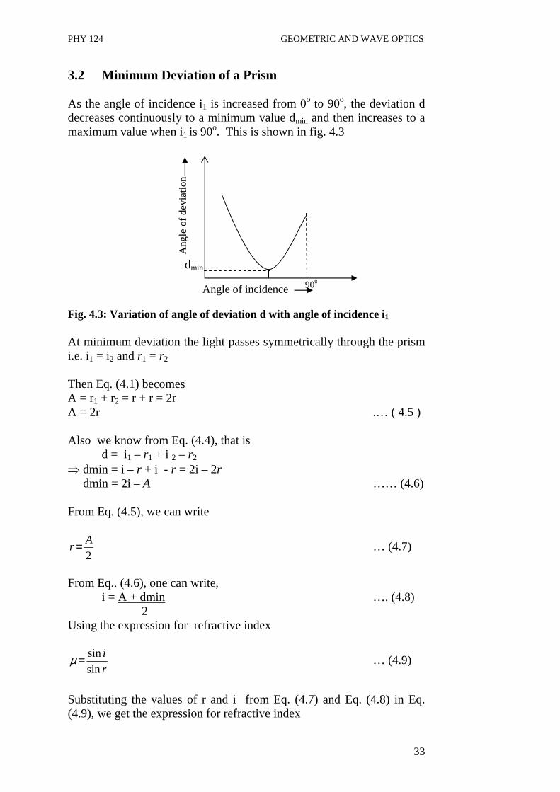
3.2 Minimum Deviation of a Prism As the angle of incidence i1 is increased from 0o to 90o, the deviation d decreases continuously to a minimum value dmin and then increases to a maximum value when i1 is 90o. This is shown in fig. 4.3 Fig. 4.3: Variation of angle of deviation d with angle of incidence i1
At minimum deviation the light passes symmetrically through the prism i.e. i1 = i2 and r1 = r2 Then Eq. (4.1) becomes A = r1 + r2 = r + r = 2r A = 2r .… ( 4.5 ) Also we know from Eq. (4.4), that is
d = i1 – r1 + i 2 – r2 ⇒ dmin = i – r + i - r = 2i – 2r dmin = 2i – A …… (4.6)
From Eq. (4.5), we can write
2
Ar = … (4.7)
From Eq.. (4.6), one can write,
i = A + dmin …. (4.8) 2 Using the expression for refractive index
r
i
sin
sin=µ … (4.9)
Substituting the values of r and i from Eq. (4.7) and Eq. (4.8) in Eq. (4.9), we get the expression for refractive index
Ang
le o
f de
viat
ion
Angle of incidence
dmin
900

PHY 124 GEOMETRIC AND WAVE OPTICS
34
∴
+
=
2sin
2sin min
A
dA
µ .… (4.10)
Eq. (4.10) is the expression for the refractive index in terms of minimum deviation and refracting angle A. Since i1 = i2 at minimum deviation, it means that minimum deviation value is for only one angle of incidence. Example 4.1 A certain prism is found to produce a deviation of 51o 0′, while it produces a deviation of 62o 48′ for two values of the angle of incidence namely 40o 6′ and 82o 42′ respectively. Determine the refracting angle of the prism, the angle of incidence at minimum deviation and the refractive index of the material of the prism.
Solution We know that d = (i1 – r1) + (i2 – r2) = (i1 + i2) – (r1 + r2) Therefore, it can be rewritten as d = (i1 + i2) – A The values are given as d = 62o 48′, i1 = 40o 6′, i2 = 82o 42′ Substituting these values in the above equation ∴62o 48′ = (40o 6′ + 82o 42′) – A We get the value of the refracting angle A as To calculate the angle of incidence at minimum deviation we use the relation, i= A + dmin 2 A = 60o, dmin = 51o 0′
A = 60o
PHY 124 GEOMETRIC AND WAVE OPTICS
35
i = 60 + 51o 0′ 2 The refractive index of the prism is given by
+
=
2sin
2sin min
A
dA
µ µ =
Now substituting the values, we get
+
=
2
60sin
2
`05160sin
0
00
µ
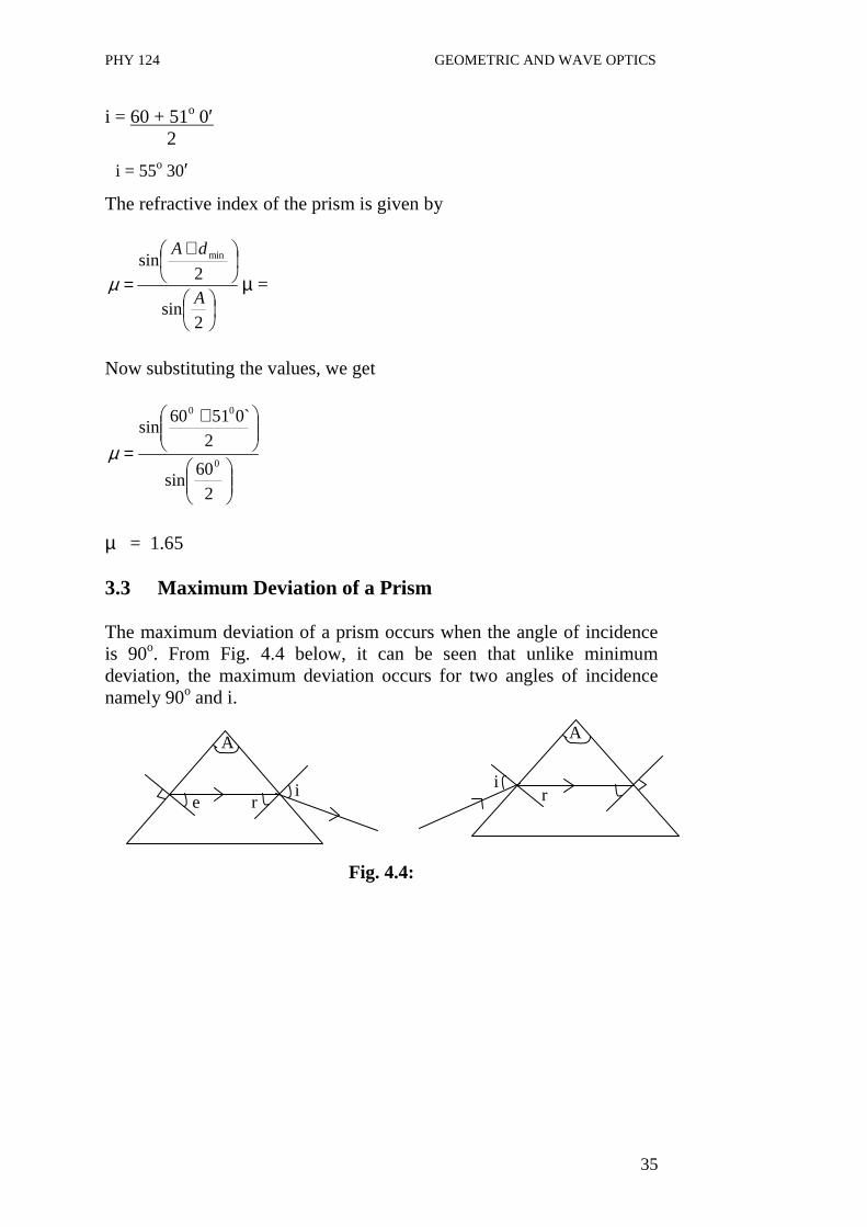
µ = 1.65 3.3 Maximum Deviation of a Prism The maximum deviation of a prism occurs when the angle of incidence is 90o. From Fig. 4.4 below, it can be seen that unlike minimum deviation, the maximum deviation occurs for two angles of incidence namely 90o and i.
Fig. 4.4:
i = 55o 30′
A
e r i
A
r i
PHY 124 GEOMETRIC AND WAVE OPTICS
36
3.4 Grazing Incidence and Grazing Emergence
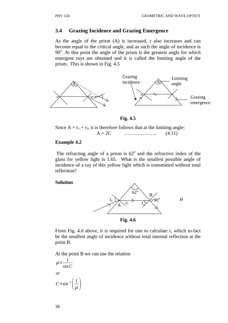
As the angle of the prism (A) is increased, r also increases and can become equal to the critical angle, and as such the angle of incidence is 90o. At this point the angle of the prism is the greatest angle for which emergent rays are obtained and it is called the limiting angle of the prism. This is shown in Fig. 4.5
Fig. 4.5
Since A = r1 + r2, it is therefore follows that at the limiting angle: A = 2C ……………….. (4.11)
Example 4.2 The refracting angle of a prism is 62o and the refractive index of the glass for yellow light is 1.65. What is the smallest possible angle of incidence of a ray of this yellow light which is transmitted without total reflection? Solution µ
Fig. 4.6
From Fig. 4.6 above, it is required for one to calculate i1 which in-fact be the smallest angle of incidence without total internal reflection at the point B. At the point B we can use the relation
=
=
−
µ
µ
1sin
sin
1
1C
or
C
A
c
A Grazing incidence
Limiting angle
Grazing emergence
62o
r1 i1 90o
A
B
C

PHY 124 GEOMETRIC AND WAVE OPTICS
37
Where µ = 1.65
=∴ −
65.1
1sin 1C
C = 37.31o Then A = r1 + C 62o = r1 + 37.31o r1 = 24.70o Also at the point A we can use the relation
1
1
sin
sin
r
i=µ
01
7.24sin
sin64.1
i=
Therefore, i1 = 43.58o 3.5 Deviation by a Small Angle Prism If the refracting angle of a prism is very small, the angle of incidence i1 in most cases would also be small which implies that the incident ray would be normal at the point of entry of the prism. Fig. 4.7: Deviation by a small angle prism. In figure 4.7, r1 is always smaller than i1. It also follows that r1 is small. and sin θ ≅ θ (for any small angle θ)
Therefore the refractive index 1
1
sin
sin
r
i
r
i ==µ
1
1
r
i≅µ
Or i1 ≅ µ r1
A
r1
r2
i2
Small angle
i1

PHY 124 GEOMETRIC AND WAVE OPTICS
38
Similarly i2 ≅ µ r2 The deviation of the ray is given by d = (i1 – r1) + (i2- r2) d = µ r1 – r1 + µ r2- r2 d = µ (r1 + r2 ) - ( r1+ r2 ) On rewriting the above equation, we get d = (µ – 1) (r1+ r2) Recall from Section 3.1 that A = r1 + r2 ∴ ……………… (4.12) Eq.(4.12) indicates that for a small angle prism the deviation is independent of the size of the angle of incidence. This means that all rays emerging from the prism are deviated by the same amount. This principle should be applied to lenses. 4.0 CONCLUSION A prism is a glass block, but triangular in shape. It may be equilateral or isosceles in shape. The angle at the apex of the prism forming the triangle is known as the angle of the prism or refracting angle. A ray of light incident on one side is refracted by the prism and emerges at the adjacent side with the direction of emergence being different from that of incidence. The difference between the directions of the emergent ray and the incident ray is known as the angle of deviation. The minimum value of the angle of deviation is known as the angle of minimum deviation and when this occurs the ray passes symmetrically through the prism. This value occurs for only one value of angle of incidence. On the other hand, the maximum angle of the deviation is known as the maximum deviation. Two angles of incidence give rise to the maximum deviation of which one is 90o. When the angle of the prism is very small we say the prism is thin. For this type of prism the angle of deviation is independent of the angle of incidence of the prism. At a certain angle of the prism, the angle of incidence and emergence is 90o, in this case we have grazing incidence and grazing emergence.
d = (µ - 1) A

PHY 124 GEOMETRIC AND WAVE OPTICS
39
5.0 SUMMARY • A prism is a triangular glass block; • The angle of the apex of the prism is known as the angle of the
prism or the refracting angle; • The change in direction between the incident ray and the
emergent ray is known as the deviation of the ray and the angle between these directions is known as the angle of deviation;
• Minimum deviation occurs for only one angle of incident and when this occurs the ray passes symmetrically through the prism;
• Maximum deviation occurs for two angles of incidence and these are 90o and any other angle i;
• The deviation for a small angle prism (this) is independent of the angle of incidence;
• For a particular refracting angle it is possible to have grazing incidence and grazing emergence.
6.0 TUTOR-MARKED ASSIGNMENT 1. Determine the angle of deviation of a ray by a glass prism with a
prism angle of 3o if the angle of incidence of the ray on the front face of the prism is zero. The refractive index of the glass material is 1.5.
2. Calculate the angle of minimum deviation of a prism if its
refracting angle is 60o. The refractive index of the material of the prism is 1.632.
7.0 REFERENCES/FURTHER READINGS Nelkon and Parker. Advance Level Physics. British Library Publication. Kenneth .W. Ford. Basic Physics. Toronto London: Waltham
Massachusetts. Mark .W. Zemansky. College Physics. London: Addison – Wesley. Shortley and Williams. Principles of College Physics. Englewood Cliff
New Jersey: Prentice Hall Inc.

PHY 124 GEOMETRIC AND WAVE OPTICS
40
UNIT 5 REFRACTION AT CURVED SURFACE CONTENTS 1.0 Introduction 2.0 Objectives 3.0 Main Content
3.1 Image Formed By a Refraction at a Curved surface 3.2 Refraction Through Lenses
3.2.1 The Major Features of a Lens 4.0 Conclusion 5.0 Summary 6.0 Tutor-Marked Assignment 7.0 References/Further Readings 1.0 INTRODUCTION Just as reflection takes places at curved and plane surfaces, similarly, refraction can also occur at plane and curved surfaces. In the last unit, we have discussed about the refraction through a prism. In this unit we shall look at refraction at curved surfaces. Fig. 5.1 shows refraction at a curved surface.
Fig. 5.1: Refraction at curved surface (a) Convex spherical refracting surface (b) Concave spherical refracting surface.
2.0 OBJECTIVES After studying this unit, you will be able to: • distinguish between refraction at a plane surface and at a curved
surface • state the equation governing the relationship between the image
distance (v), object distance ( u ) and the parameters of the curved refracting surface
Q
O P
I
u v
C
2µ
I
2µ 1µ
(a) (b)
2µ 1µ
2µ

PHY 124 GEOMETRIC AND WAVE OPTICS
41
• solve problems related to u, v and parameters of the curved refracting surface
• define a lens and to identify its characteristics features. 3.0 MAIN CONTENT 3.1 Image Formed by Refraction at a Curved Surface In Fig. 5.1, point O is an object near a convex spherical refracting surface of radius of curvature r. The surface separates the two media whose indices of refraction differ, that of the medium in which the incident light falls on the surface being µ1 and that on the other side of the surface being µ2. A light source ray that enters normally at the point P would pass through undeviated and pass through the center of curvature. A bright ray that enters at any other angle (Q for example) would be deviated or converged to intersect with a ray that passing through the center of curvature to produce a real image 1. If the surface were concave then the refracting ray would diverge and if produced backwards would form a virtual image as shown in Fig. 5.1 (b). The object and image distance are related by the formula (here we have written only the result. The formula is not derived.)
rvu1221 µµµµ −
=+ ……………. (5.1)
Where
u = object distance v = image distance r = radius pf curvature of surface µ1, µ2 = refractive index of the two media Note that µ1, is the refractive index of the medium in which the light is originally traveling before it gets into medium with refractive index µ2. It is to be noted that that we must use sign conventions if we are to use this equation to a variety of cases. The side of the surface in which light rays originate defined as the front side. The other side is called as the back side. Real images are formed by refraction in back of the surface in contrast with the mirrors, where real images are formed in front of the reflecting surface. Because of the difference in location of real images, the refraction sign conventions for v and r are opposite the reflection sign conventions.

PHY 124 GEOMETRIC AND WAVE OPTICS
42
Just as in refraction the image formed can be enlarged or diminished and the magnification of the image is given by
u
vm
2
1
µµ
=
The symbols have their usual meaning. Example 5.1 One end of a cylindrical glass rod of refractive index 1.5 is a hemispherical surface of radius of curvature 20 mm. An object is placed on the axis of the rod at 80 mm to the left of the vertex of the surface (a) Determine the position of the image (b) Determine the position of the image if the rod is immersed in water of refractive index 1.33. Solution
Fig. 5.2 (a) The object distance u = 80 mm
The radius of curvature r = 20 mm As earlier discussed in unit (sign convention), if the side from which the light is coming is concave then r would be negative. Since the light ray is traveling from air to glass µ1 = 1 (for air) and µ2 = 1.5 (for glass) Using the formula
rvu1221 µµµµ −=+
Substituting the values in the above Eq., we get
20
15.15.1
80
1 −=+v
r = 120 mm (to the right of the curved surface)
80m
O
r = 20mm
I

PHY 124 GEOMETRIC AND WAVE OPTICS
43
(b) Since the glass rod is now immersed in water( µ1 = 1.33 ), therefore
rvu1221 µµµµ −=+
20
15.15.1
80
33.1 −=+v
v = - 184.6 mm The negative sign indicates a virtual image
3.2 Refraction through Lenses The phenomenon of refraction is the change in direction of a ray of light when it travels from one medium to another of different density. Refraction through lenses involves the same change in the direction of light rays. A lens is a portion of a transparent medium bounded by two spherical surfaces or by a plane and a spherical surface. The various types of lenses are shown in Fig. 5.3. Biconvex Plano-convex Bi-concave Plano-concave (a) Converging lenses (b) Diverging lenses
Fig. 5.3: Various types of lenses. Generally, a converging or convex lens makes rays of light originating from a point come together at another point while the diverging or concave lens makes rays of light which pass through a point spread out or diverge. 3.2.1 The Major Features of a Lens A typical lens of whatever type has the major features illustrated in Fig. 5.4.

PHY 124 GEOMETRIC AND WAVE OPTICS
44
F C C
Fig. 5.4: Major features of a lens. i) The Principal Axis This is the line joining the centers of curvature of the two curved surfaces forming the lens. ii) Optical Centre For every lens there is a point C through which rays of light pass through without being deviated by the lens. This point is called the optical center of the lens. (see figure 5.1) iii) The Principal Focus The principal focus F of a converging lens is the point to which all rays parallel and close to the principal axis converge after refraction through the lens. The principal focus of a diverging lens is the point from which all rays parallel and close to the principal axis appear to diverge from after refraction through the lens. iv) Focal Length The focal length F is the distance between the optical center and the principal focal of the lens. Note that the principal focus of a converging lens is on the far side from the incident rays while for the diverging lens the principal focus is on the same side as the incident rays and the refracted rays do not actually pass through it (refer Fig. 5.4).
4.0 CONCLUSION A lens is a portion of a transparent medium bounded by two spherical surfaces or by a plane and a spherical surface.
Principal axis
(b) Diverging lens (a) Converging lens
Principal axis F

PHY 124 GEOMETRIC AND WAVE OPTICS
45
When refraction takes place at a curved surface, this results into an image formation. The magnification m of the image is given by the expression,
u
vm
2
1
µµ
=
The equation relating the image distance v to the object distance u and the radius of curvature r and refractive index of the curved refracting medium is
rvu1221 µµµµ −
=+
A typical lens has an optical axis, principal axis, principal focus, center of curvature. For a converging lens the light rays close to the principal axis are brought to the focus on the side of the lens where as in a diverging lens, parallel rays close to the principal axis diverge or appears to come from the focus at the same side as the incident rays. 5.0 SUMMARY
• Unlike refraction at a plane surface, refraction at curved surface results in image formation which can be real or imaginary.
• A lens is a portion of a transparent medium bounded by two spherical surfaces. Therefore refraction through a lens involves refraction at two curved surfaces.
• A typical lens has an optical center, principal focus, principal axis and center of curvature.
6.0 TUTOR-MARKED ASSIGNMENT A small tropical fish is at the center of a spherical fish bowl 1m in diameter. Determine the position and the lateral magnification of the image of the fish seen by an observer outside the bowl. The refractive
index of water is 3
4

PHY 124 GEOMETRIC AND WAVE OPTICS
46
7.0 REFERENCES/FURTHER READINGS Nelkon and Parker. Advance Level Physics. British Library Publication. Kenneth .W. Ford. Basic Physics. Toronto London: Waltham
Massachusetts. Mark .W. Zemansky. College Physics. London: Addison – Wesley. Shortley and Williams. Principles of College Physics. Englewood Cliff
New Jersey: Prentice Hall Inc.

PHY 124 GEOMETRIC AND WAVE OPTICS
47
MODULE 2 LENSES AND OPTICAL INSTRUMENTS Unit 1 Images Formed by a Converging Lens and Diverging Lens
(Ray Tracing) Unit 2 Lens Formula and Spectra Unit 3 The Eye Unit 4 Optical Instruments Unit 5 Other Types of Telescopes UNIT 1 IMAGES FORMED BY A CONVERGING LENS
AND DIVERGING LENS (RAY TRACING) CONTENT 1.0 Introduction 2.0 Objectives 3.0 Main Content
3.1 Images Formed by a Convex (Converging) Lens 3.1.1 Object Placed at Position 2f 3.1.2 Object at Principal focus 3.1.3 Object between F and the lens
3.2 Images Formed by Concave Lens 4.0 Conclusion 5.0 Summary 6.0 Tutor-Marked Assignment 7.0 References/Further Readings 1.0 INTRODUCTION In Unit 5, we have discussed that refraction at a curved surface gives rise to image formation. That is, if an object is placed in front of a curved refracting surface, the image of the object is formed. This is also true of a lens which, as we have also discussed in Unit 5, consists of two refracting curved surfaces. In this Unit, you will study how images are formed by lenses (either converging or diverging) for various object positions. This unit will concentrate on using ray diagrams to determine the position of images formed by such lenses. As we have discussed about the refraction. The law of refraction is responsible to govern the behavior of lens images.

PHY 124 GEOMETRIC AND WAVE OPTICS
48
2.0 OBJECTIVES After studying this Unit, you will be able to: • trace rays to locate the image formed by a convex lens for various
objects distances • trace the rays to locate the image formed by a concave lens for
various object distances • distinguish the differences between images formed by convex
and concave lenses • solve problems associated with images formed by convex and
concave lenses using ray tracing. 3.0 MAIN CONTENT
3.1 Images Formed by a Convex (Converging) lens
In this section discussion is on the image formed by a convex (converging) lens. Here, we are going to look at how the image of an object is formed by a convex lens for the three different object position discussed below. The method is illustrated in Fig. 5.1 (a), 5.1 (b) and 5.1 (c).
In using the ray diagram to determine the position of the image of an object formed by a lens either (convex or concave), a set of rules, similar to rules that govern the reflection case, exist. These are as follows: (i) a ray parallel to the principal axis incident on one side of the lens
is refracted to the far side of the lens through the far focus as shown in Fig.51 (a).
Fig. 5.1 (a): A ray parallel to the principal axis passes through the
focus on the far side of the lens.
(ii) A ray passing through the near focus on one side emerges parallel to the principal axis on other side as shown in Fig 5.1 (b).
F
Fig. 5.1 (b): A ray coming through the near focus becomes parallel to the principal axis on the other side.
F F

PHY 124 GEOMETRIC AND WAVE OPTICS
49
(iii) A ray incident along the optical centre of the lens goes through to the other side without any deviation as shown in Fig. 5.1 (c).
Fig. 5.1 (c): A ray incident along the optical centre of the line is
undeviated and passes to the other side without any deviation.
As it will be seen in the case discussed below, the use of any two of three rays is sufficient to determine the location and magnitude of the image.
3.1.1 Object Placed at Distance Greater than 2f
P I
Fig. 5.2: Shows the image formed when the object placed at a
distance greater than 2f. Fig. 5.2 shows the ray diagram for the image formed by a convex lens of focal length f, in which object OP is placed at distance greater than 2f from the lens. Ray PQ which is parallel to the principal axis is refracted through the principal focus to give ray QR. Then the ray PC which is directed towards the optical center C of the lens through the lens undeviated to give ray CR. The two refracted rays QR and CR intersect at R to form the image IR. So, therefore IR gives the magnitude of the image and CI the image distance and OC is the object distance so the magnification M as earlier defined equal to
M = IR = CI = Image distance OP OC Object distance
F F C
2f f C
Q
Object distance
O f
Image distance
R
PHY 124 GEOMETRIC AND WAVE OPTICS
50
It can be seen from Fig. 5.2 that the image formed (IR) is real, inverted and magnified. 3.1.2 Object Placed at the Position 2f
O 2f
Fig. 5.3: A ray diagram for an object placed at 2f
Fig. 5.3 shows the ray diagram for the image formed by a convex lens of focal length f when the object distance is 2f. The two rays considered are similar to those in Fig. 5.2. It can be seen from Fig. 5.3 that the image formed is real, inverted, and of unit magnification. That is, the size of the image is same as that of the object. 3.1.3 Object is kept at Principal Focus
Fig. 5.4: A ray diagram for an object placed at f. Fig. 5.4 shows the ray diagram for the image formed by a convex lens when the object is kept at focus which is at focal length f. Considering just the two rays either discussed above, ray PQ parallel to the principal axis is refracted through the far focus to give ray Qf. On the other hand ray PC goes through the optical centre of the lens undeviated on the other side. Thus, we have a set of parallel rays emerging on the other side of the lens. Since parallel rays (lines) only converge infinity, it applies that the image formed under this condition is at infinity. Thus, the image formed by a convex lens, when the object is placed at the principal focus, is at infinity.
f C
Q
f
R
I
P
f f C
Q
O
P
PHY 124 GEOMETRIC AND WAVE OPTICS
51
3.1.4 Object kept between f and the Lens
R
Fig. 5.5: A ray diagram for an object kept between f and the lens. Fig. 5.5 shows a ray diagram for image formed by convex lens when the object distance is less than the focal length of the lens. Ray PQ is refracted to give ray Qf while ray PC, as usual, is undeflected. Consequently, the emerging, (refracted rays) diverge and appear to come from point R consequently given rise to image IR. From Fig. 5.5 it can be seen that the image IR is virtual, erect and magnified. 3.2 Images Formed by Concave Lens
Fig. 5.6: Image formed by a concave lens. Fig. 5.6 shows the ray diagram for the image formed by a concave (diverging) lens. As can be seen from this figure that a ray PQ, parallel to the axis, diverges at the other side of the lens after refraction to give ray QR, ray PC through the optical center of the lens passes through to the other side of the lens without any deviation. Hence, the image is formed by the intersection of the apparent source of the divergent ray (dotted line) and ray PC. These two rays intersect at R. therefore, IC gives the image distance and IR gives the magnitude of the image. As before the magnification of the image can be written as
f f C
Q
O
P
I
P
O f I
R
f C
Q

PHY 124 GEOMETRIC AND WAVE OPTICS
52
M = IR = IC OP OC It can be observed from Fig. 5.6 that the image formed is imaginary, it is erect and it is diminished. Also it has been found that irrespective of the position of the Object, the shape of image and type of the image formed are always the same. Example 1.1 An object 3 cm tall is placed 30 cm in front of a convex lens of focal length 10 cm. Determine using a ray diagram (i) magnification of the image (ii) the image distance Solution Choose a suitable scale e.g. 1 cm = 5 cm I 0.4 cm
Fig. 5.7
∴ The object distance OC = 30 cm= 6cm (in choosen unit) Object height OP= 3cm =0.6cm ( in choosen unit) Utilizing the above information, the resulting ray diagram is shown
in Fig. 5.7. IR as indicated earlier is the magnitude of the image and OC is the object distance.
So (i) Using the definition of magnification
M = IR OP Which means the image is diminished, it is reduced by half.
(ii) the image distance IC = (3x5) cm = 15 cm
f C
Q
6 cm
O f
3.2 cm R
10 cm
0.6 cm P

PHY 124 GEOMETRIC AND WAVE OPTICS
53
Example 1.2 If the object in example 6.1 above is placed 15 cm away from lens, what will be (i) the height of the new image formed? (ii) the new image distance?
C
Fig. 5.8 IR = 1 cm = 5cm IC = 5cm = 25 cm
Solution Refer Fig. 5.8 (i) The new height of the image = (1.0 x 5) cm = 5 cm
∴The new magnification = 5.0 cm = 1.67 cm 3.0
(ii) The new image distance = (5 x 5) cm = 25 cm So that there is a magnification 1.67 times which means the image is enlarged.
4.0 CONCLUSION The image formed by convex and concave lens can be determined by ray tracing for various object distance. For obtaining these images, the basic rules to be followed are; (i) Rays parallel to the principal axis incident to the lens on one side
of a convex lens are brought to a focus on the other side of the lens after refraction of the lens. For the concave lens, on the other hand, the rays are diverge from the same side as the incident parallel rays are appear to be brought to a focus on the far focus.
(ii) For a convex lens, rays emanating from focus on one side incident on the one side of the lens emerge parallel to the principal axis on other side. For a concave lens, such rays are reflected on the same side parallel to the principal focus.
f
Q
2 cm O 2 cm
R
P
I
1cm
5.1cm

PHY 124 GEOMETRIC AND WAVE OPTICS
54
(iii) Light rays directed to the optical centre of the lens (whether Convex or Concave) pass through the lens to the other side undeviated.
When the object distance for a convex lens is greater than 2f, the image formed is real, inverted and magnified. When the object distance for a convex lens is equal to 2f, the image formed is real, inverted and of unit magnification. When the object distance for a convex lens is at f, the image is formed at infinity. When the object distance is less than f the image formed is virtual, erect and magnified. Finally, the image formed by a concave lens is always virtual and erect.
5.0 SUMMARY Ray tracing is an interesting technique to determine the images formed by concave and convex lenses. The three rules governing the rays are summarized as in Section 3.1 above. The characteristics of image formed by convex lens are as follows: When object distance is greater than 2f then image formed is as follows: (i) Real (ii) Inverted (iii) diminished. The characteristics of image formed by convex lens when the object is kept at 2f are; (i) Real (ii) Inverted (iii) It is of unit magnification When the object is placed at the focal point of a convex lens, the image is formed at infinity. The characteristics of image formed by a convex when the object distance is less than f is as follows: (i) it is virtual (ii) it is erect (iii) and it is enlarged
PHY 124 GEOMETRIC AND WAVE OPTICS
55
The image formed by a concave lens irrespective of its object distance is always virtual and erect and upright. It may be diminished or enlarged.
6.0 TUTOR-MARKED ASSIGNMENT 1.a) A convex lens with focal length 15 cm is placed 45 cm away
from the object 2.5 cm tall (a) Determine the position and the size of the image.
b) If the convex lens were a concave lens, what is the value of the magnitude of the image and the image distance?
7.0 REFERENCES/FURTHER READINGS
Nelkon and Parker. Advance Level Physics. British Library Publication. Kenneth .W. Ford. Basic Physics. Toronto London: Waltham
Massachusetts. Mark .W. Zemansky. College Physics. London: Addison – Wesley. Shortley and Williams. Principles of College Physics. Englewood Cliff
New Jersey: Prentice Hall Inc.

PHY 124 GEOMETRIC AND WAVE OPTICS
56
UNIT 2 LENS FORMULA AND SPECTRA CONTENTS 1.0 Introduction 2.0 Objectives 3.0 Main Content
3.1 The Lens Formula 3.2 The Lens Makers’ Equation 3.3 Dispersion and Spectra 3.4 Spectra
3.4.1 Types of Spectra 4.0 Conclusion 5.0 Summary 6.0 Tutor-Marked Assignment 7.0 References/Further Readings 1.0 INTRODUCTION In Unit 1, we discussed how to obtain image distance and the magnification of the image by ray tracing formed by convex and concave lenses for different object distances. The same kind of information can be obtained using the lens formula. This equation relates the focal length f to the object distance u and image distance v of a lens to the refractive index and the radii of curvature, r1 and r2 of the curved surface of the lens. Also, there is another equation that relates the focal length of a lens to its refractive index and the radii of curvature of the lens, this law is known as the lens maker’s law. You will know more about these laws while you study this unit. Further in this unit, you will study about dispersion of white light, that is, how white light is splits into its different colour components by a glass prism. As you will see in Section 3.2, dispersion is related to the angle of deviation i.e. dispersion is due to the fact that the various colour component of white light are associated with different angles of deviation while traveling through glass prism. In addition, in this Unit, you will study different types of spectra.
PHY 124 GEOMETRIC AND WAVE OPTICS
57
2.0 OBJECTIVES After studying this unit, you will be able to: • state the lens maker’s law • apply the lens maker’s law in solving problems • define and explain dispersion • identify the colours of white light • differentiate and explain different kinds of spectra. 3.0 MAIN CONTENT 3.1 The Lens Formula It has been found that there is a mathematical relationship linking the focal length of a lens (f), the object distance from the lens (u) and image distance from the lens (v). This relation is given as
uvf
111 −= …… (2.1)
This Eq.(2.1) is the same as that for curved mirrors (concave or convex). Hence, if any two of these parameter f, u and v are known, Eq. (2.1) can be used to determine the third unknown parameter. Consequently, this equation can be used to derive the same pieces of information obtained in Unit 6 by ray tracing. 3.2 The Lens Makers’ Equation The best way to represent the focal length of a lens is by using the radius of curvature of the two faces (or surfaces). Now in this section, we will derive an expression for the focal length f of a convex lens. Here, it is assumed that the ray falls on the flat surface of the lens and these surfaces at which a ray enters and leaves similar to the surfaces of a prism. So, we will use prism formula to determine the deviation d.

PHY 124 GEOMETRIC AND WAVE OPTICS
58
Fig. 2.1 (a): Convex lens
When a ray of light enters a prism, it deviates. Let d be the angle of deviation of light from a small angle prism. The small angle of the prism is A. Let µ is the refractive index of the glass. Then the expression for the deviation of a ray passing through a prism can be written as d = (µ - 1) A ……(2.2) But from Fig. 2.1 (a), it is observed that the light rays are parallel to the principal axis. To focus these light rays on the focal point f, each ray is deflected by an angle θ, then
f
hd = …..(2.3)
(here the value of θ is small <15o) It means that all light rays do not hit lens too far from its centre. It is also known that a transparent material whose surface is spherical will deflect light rays according to Eq. 7.3 i.e. will make useful lens. Combining Eq. (2.2) and (2.3), we get another expression,
Af
h)1( −= µ
Principal axis
h
f f d
lens
d
d
r1 r2
h α β
A
Fig. 2.1(b)
A
Fig. 2.1(c) A
β∝

PHY 124 GEOMETRIC AND WAVE OPTICS
59
Rewriting the above equation in another form, we get
h
A
f)1(
1 −= µ …. (2.4)
from Fig. 2.1 (b), it can be seen that r1 and r2 are the radius of curvature and
d = α + β …… (2.5)
(The sum of two interior opposite angles is equal to the exterior angle) and d = A ….. (2.6)
Now substituting Eq. (2.6) in Eq. (2.5), and also substituting the values of
21 r
hand
r
h == βα
we get
21 r
hand
r
h == βα or 21
11
rrh
A += …. (2.7)
Substituting Eq. (2.7) into Eq.( 2.4), we get
+−=
21
11)1(
1
rrfµ …… (2.8)
So, now you can see a relation between focal length of a lens in terms of its refractive index and radius of curvature. Now, it can be seen from the Eq. (2.8) that to obtain a short focal length f the lens should have a small value of r1 and r2 and refractive index of the material should be high. The Eq. (2.8) is known as the lens maker’s equation. It can also be noted that the values of the radii of curvature of the two spherical surfaces, which a lens of required focal length should have, can be determined by using this formula. Then the two surfaces of glass can be given the calculated value of the radii of curvature. Hence, the lens so produced will possess the required focal length.

PHY 124 GEOMETRIC AND WAVE OPTICS
60
Example 7.1 A pin is placed 40 cm away from a convex lens of focal length 15 cm. Determine the magnification of the pin formed by the lens.
Solution Focal length (f ) of the lens = 15 cm Object distance ( u) = 40 cm The image distance ( v) is to be determined
Using Eq. (2.1)
fuv
111 =+
On rearranging the terms on either side, we get
ufv
111 −=
Now substituting the given values
40
1
15
11 −=v
120
5
120
381 =−=v
120
51 =v
∴ v = 24cm But Magnification is defined as
u
vM =
Again substituting the values, we get
24
40=
∴ M = 1.67

PHY 124 GEOMETRIC AND WAVE OPTICS
61
Intensity and colour are the two properties of light. The colour of the light is related to the wavelength or frequency of the light. The intensity (brightness) of light is related to the square of the amplitude of the wave. The visible spectrum to which our eyes are sensitive lies in the range of 450 x 10-9m to 750 x 10-9m . Within this spectrum lie the different colours from violet to red. Light with wavelength shorter than 450 x 10-9m is called ultraviolet and light with wavelength greater than 750 x 10-
9m is called infrared. It is to be noted that human eyes are not sensitive to ultraviolet and infrared. In your physics course earlier, you come across with the prism. A prism is a triangle (wedge) shaped piece of transparent material make up of glass. So, what happens if while light from a source is passed through this prism? Let us discuss about it. 3.3 Dispersion and Spectra It is found that if white light, such as light from the sun, passes through a prism, an elongated coloured patch of light is obtained on a screen placed behind the prism as shown in Fig. 2.2.
Fig. 2.2: A white light pass through a prism This patch of light is called a spectrum and it consist of the following colours arranged in the order of presentation with the red light rays having the least of deviation and the violet light rays having the most angle of deviation. The incident white light actually consists of these colours combined but because each component colour has different speed in the glass medium. However, in ordinary air, the speed of each of these components is virtually the same and these components cannot be differentiated as they travel together with a common speed. However, in a medium like glass these components travel with different speeds (i.e. red travel with the fastest speed and violet is the slowest) and therefore they are associated with different angles of deviation. (Also we have learnt that light of different wave lengths bent at different angles when falls on a refracting material. The index of refraction of material depends on the wavelength.) Therefore, the component splits into their different colours as they travel through glass and separated the white light into its various colours
Spectrum (impure)
Screen(S)
Prism
White light
PHY 124 GEOMETRIC AND WAVE OPTICS
62
The wavelength of red light in air is 750 x 10-9m (the longest wavelength) and violet light has a wavelength in air 450 x 10-9m (the shortest wavelength). As shown in Fig. 2.2, a band of impure colours is obtained on a screen S. The separation of colours (red, orange, yellow, green, blue, indigo and violet) by a prism is called dispersion. In simple words, the spreading of white light into the full spectrum is called dispersion. The formation of rainbows is a natural example of dispersion. The prism alone produces what is called an impure spectrum or continuous spectrum in which different colours overlap. Therefore in order to produce a pure spectrum, the set up is as shown in Fig. 2.3. Fig. 2.3: Two convex lenses in addition to the prism to obtain pure
spectrum. After discussing the dispersion in this section, now in section 3.4 the topic of spectra will be discussed. Here also, we will familiarize you with the different type of spectra. 3.4 Spectra Spectra is the study of wavelengths of the radiation coming out from a hot body. There are two types of spectra, the emission spectra and the absorption spectra. Emission spectra When an atom is heated, it’s electrons gain thermal energy until it gets to the excited state. And within a very short time, the electron can go back to a lower energy level, thereby emitting energy in the form of photons. For example, iron has 400 different wavelengths in its spectrum, but a very element has a unique spectrum characteristics of it’s atoms. Consequently a study of the spectrum of a substance enables
Source of light
Convex lens
Convex lens
Screen
Pure spectrum

PHY 124 GEOMETRIC AND WAVE OPTICS
63
its composition to be readily determined. Spectroscopy is the analysis of mixtures or compounds by a study of their spectra. 3.4.1 Types of Spectra 1. Line Spectra This is the type of spectra obtained from atoms or molecules and is displayed in the form of lines. The line spectrum is obtained when a gas is heated or a large electric current is passed through it. It is important to note that, only certain wavelengths of light are emitted and these are different far different elements and compounds. These lines are actually the image of the narrow slit of the spectrometer in which the light is incident. These lines occur in series as shown in the Fig. 2.4 below.
Series of lines
Fig.2.4: Line spectra for series of lines The various series and their wavelength are:
Lyman series: ,1
1
112
−=µλ
R , µ = 2,3, ……………
Balmer Series : ,1
2
112
−=µλ
R µ = 3,4,5…………..
Paschen Series ,1
3
112
−=µλ
R µ = 4,5…………….
Bracket series: ,1
4
112
−=µλ
R µ = 5,6………………
where R is a Rydberg constant = 1.097 x 10⁷ m-1 2. Band Spectra This is the kind of spectra obtained from molecules and it consists of bands (fine lines) sharp atom end and at the other end as shown in Fig. 2.5.

PHY 124 GEOMETRIC AND WAVE OPTICS
64
Fig. 2.5: Band Spectra
3. Continuous Spectra This is kind of spectra obtained from solids and liquids. Since the atoms and molecules are closely packed, there interaction exists between neighboring atoms, such that all radiations of different wavelength are emitted. For example, light bulb filament produces a continuous spectrum. 4. Absorption Spectra When a white light (for example a continuous spectrum) is passed through a sodium, the flame absorbs from the light, a wavelength equal to that which it can emit at that state (temperature). This will produce a dark line with in the continuous spectrum when viewed with a spectrometer. This dark line is a natural characteristic of the absorbing substance (sodium). Also atom and molecules absorb light at the same wavelength at which they emit light i.e. if we look at sun’s continuous spectrum, it will contain a number of dark lines called absorption lines. This kind of spectra is called absorption spectra. Example 2.2 When an object is placed 10 cm away from a lens it is found that the image formed 5 cm behind the object on the same side of the lens (i) Determine the focal length of the lens (ii) the magnification and (iii) type of image. Solution (i) The object distance, u = 10 cm
The image distance, v = - (10 + 5) cm (since the image is on the same side as the side of the object.)
Because the image distance is negative, Eq. 2.1 becomes
vuf
111 −=
That is on inserting the values of the parameters, we get
15
1
10
11 −=f

PHY 124 GEOMETRIC AND WAVE OPTICS
65
30
11. =
fei
∴ f = 30 cm. (b) Since the sign of f is positive, the lens concerned must be a
convex one as by convention, a convex lens has positive focal length.
Magnification, u
vM =
But v is negative, therefore the magnification is
10
15−=∴ M
M = - 1.5 Actually, the negative sign of the magnification, M and the image distance, v shows the image is virtual. Example 2.3 The curved face of a plano- convex lens of refractive index 1.5 is placed in contact with a plane mirror. An object at a distance of 20 cm coincides with the image produced by the lens and reflects by the mirror. A film of liquid is now placed between the lens and the mirror and the coincident object and image are at 100 cm distance. Determine the refractive index of the liquid.
Fig. 2.6(a)
Plano-convex 20 cm

PHY 124 GEOMETRIC AND WAVE OPTICS
66
Fig. 2.6(b) Solution In Fig 2.6 (a), the rays reflected by mirror are parallel. Therefore, they would converge at the focus of the overlying lens after reflection. Similarly, when the space between the lens and the mirror is filled with liquid the reflected rays converge at the joint focus of Plano concave lens formed by the liquid and the existed Plano convex lens after refraction through these two lenses. This implies that f1 = 20 cm, f = 100 cm. Relating the focus lens to their joint focal (f) is
21
111
fff+=
21
111
fff+=
20
1
100
1111
12
−=−=fff
100
41
2
−=f
25
11
2
−=f
∴f2 = - 25 cm. The negative sign indicates that the lens is a concave lens. A Plano – concave has a negative focal length. Using the lens maker’s equation for the Plano – convex lens, we have
100 cm = F
F2

PHY 124 GEOMETRIC AND WAVE OPTICS
67
+−=
21
11)1(
1
rrfµ
hence, µ is the refractive index of the glass for the Plano-convex lens r2 is infinity (r2 = ∞) because one of it’s surfaces is flat.
∞+−=∴ 11
)15.1(20
1
1r
=∞
−= 01
sin1
)15.1(1
cer
Therefore, r1 = 10.0 cm Using the lens maker’s equation for the Plano-concave liquid lens, we have
+−=
212
11)1(
1
rrfµ
where µ = refractive index of liquid f2 = - 25 cm r1 = 10 cm
011
,2
2 =∞
=⇒∞=r
r
10
1)1(
25
1 −=− µ
µ = 0.6 4.0 CONCLUSION
The lens formula is uvf
111 +=
Thus, if any two of the three parameter f, v, and u are known, then third one can be easily computed using the above Equation. Therefore the information that can be obtained about the object for image distance through ray tracing can also be obtained by using this equation.

PHY 124 GEOMETRIC AND WAVE OPTICS
68
The lens maker’s equation
+−=
211
11)1(
1
rrfµ
This equation relates a focal length, refractive index and the radii of curvature of a given lens. Consequently, if we know any of the three parameters above we can always use the equation to determine the fourth one. Dispersion is the break down of white light into its colour component. These colours are red, orange, yellow, green, blue, indigo and violet. Dispersion results from the fact that the various colour components have moved through the glass prism at different velocities and are associated with different angles of deviations. While red light has the least angle of deviation, violet has the most angle of deviation. This gives the colour spectra of white light after dispersion. The spectrum can be continuous in which case, the colours match with each other pure, in this case they appear distinctly in fine lines. 5.0 SUMMARY • The lens formula can be used to obtain the same information
about the u or v or f as by a lens by ray tracing. • The lens maker’s equation relates the focal length, the refractive
index and the radii of curvature of a given lens. • When white light passes through a prism, it splits into its basic
component colours. This is known as dispersion. • Dispersion is due to different velocities of travel and
consequently, different angle of deviation of the component colours of white light through the glass prism.
• Red light is least deviated whereas violet deviates most out of the component colours.
• The emerging ray of light received on the screen after incident, white have passed through a prism is usually in form of a continuous spectrum in which the adjacent colours interfere with each other with appropriate instrumentation, pure spectrum can be obtained.
• Other forms of spectra are band spectra and absorption spectra.

PHY 124 GEOMETRIC AND WAVE OPTICS
69
6.0 TUTOR-MARKED ASSIGNMENT 1. Determine the radius of curvature of the convex surface of a
plano convex lens if its focal length is 0.3m and the refractive index of the material of the lens is 1.5.
2. An object placed 45 cm away from a lens forms an image on a
screen placed 90 cm on the other side of the lens. (a) What type of lens it is? (b) Determine the focal length of this lens. (c) Calculate the size of the image if the size of the object is 15 cm. 7.0 REFERENCES/FURTHER READINGS Nelkon and Parker. Advance Level Physics. British Library Publication. Kenneth .W. Ford. Basic Physics. Toronto London: Waltham
Massachusetts. Mark .W. Zemansky. College Physics. London: Addison – Wesley. Shortley and Williams. Principles of College Physics. Englewood Cliff
New Jersey: Prentice Hall Inc.
PHY 124 GEOMETRIC AND WAVE OPTICS
70
UNIT 3 THE EYE CONTENTS 1.0 Introduction 2.0 Objectives 3.0 Main Content
3.1 The Human Eye 3.2 Power of a Lens 3.3 Eye Defects and Their Corrections
3.3.1 Long Sightedness 3.3.2 Short sightedness
4.0 Conclusion 5.0 Summary 6.0 Tutor-Marked Assignment 7.0 Reference/Further Readings 1.0 INTRODUCTION We have learnt about the lenses in earlier units. You can recall that how different kind of images are formed when the object is kept at different positions. Eyeglasses are now a day commonly used to correct visual problems. We use lenses to solve the problem of nearsightedness, farsightedness or to magnify object. Now, you may ask logically what goes wrong with our vision. Why are we not able to see properly? To get the answer of these questions, first, it is vital to know about the human eye and its essential parts and their functions. The eye is a natural optical instrument which an average person uses to see. It is analogous in every way to the camera. It has a lens, a shutter known as the iris and a retina which acts like film of a camera. The image of an object being viewed is formed on the retina in the same manner as the image is formed on the film of a camera. In this unit you will study about essential parts of the eye as well as the defects of the eye and their corrections. The major defects of eye are far – sightedness, and short sightedness. They are corrected using appropriate convex or concave lenses which are usually worn in form of eye glasses (spectacles).
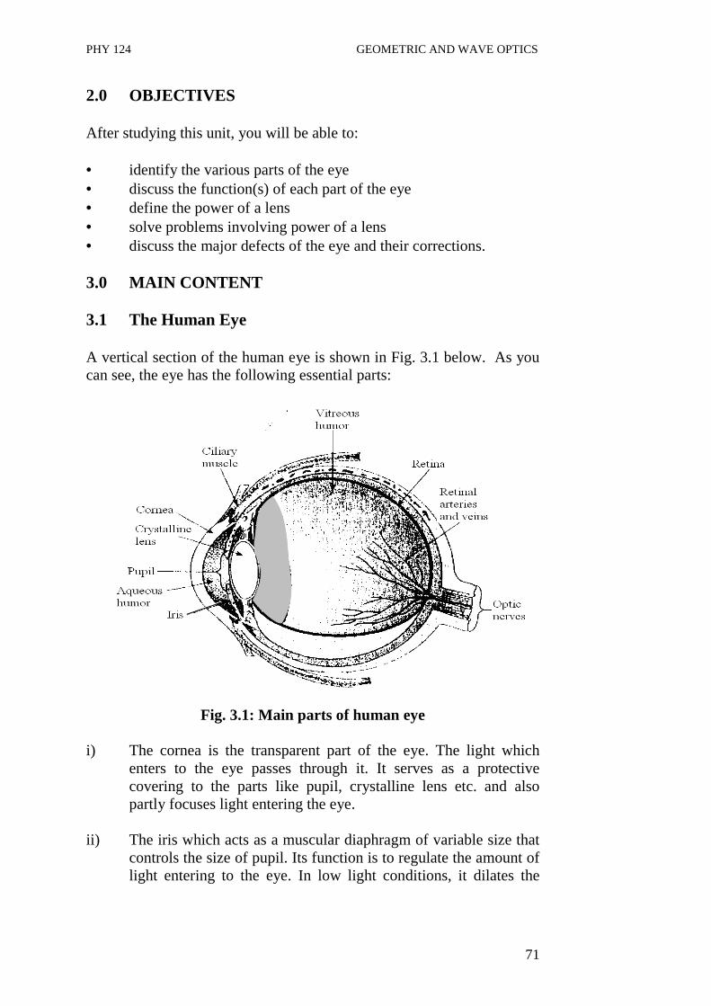
PHY 124 GEOMETRIC AND WAVE OPTICS
71
2.0 OBJECTIVES After studying this unit, you will be able to: • identify the various parts of the eye • discuss the function(s) of each part of the eye • define the power of a lens • solve problems involving power of a lens • discuss the major defects of the eye and their corrections. 3.0 MAIN CONTENT 3.1 The Human Eye A vertical section of the human eye is shown in Fig. 3.1 below. As you can see, the eye has the following essential parts:
Fig. 3.1: Main parts of human eye
i) The cornea is the transparent part of the eye. The light which
enters to the eye passes through it. It serves as a protective covering to the parts like pupil, crystalline lens etc. and also partly focuses light entering the eye.
ii) The iris which acts as a muscular diaphragm of variable size that
controls the size of pupil. Its function is to regulate the amount of light entering to the eye. In low light conditions, it dilates the

PHY 124 GEOMETRIC AND WAVE OPTICS
72
pupil and on the other hand, it contracts the pupil in high light conditions.
iii) The pupil is a circular aperture in the iris. iv) The eye lens which is supported by the ciliary’s muscles and its
function is to focus light entering the eye onto the retina. The action of the ciliary’s muscles alters the focal length of the lens by changing its shape.
v) The retina is the light sensitive portion at the back inside surface
of the eye. The optic nerves of the brain begin at the retina from which they transmit massages to the brain. The most sensitive spot of the retina is known as the yellow spot and its least sensitive portion is the blind spot, which is where the optic nerve leaves the eye for the brain. An image is perceived. The retina in the eye works in the same way as the film in a camera. It is interesting to note that our brains interpret the object scene as right side up.
vi) Cornea is the curved membrane forming the front surface of the
eye. vii) The aqueous humor is the transparent liquid between the lens and
the cornea. viii) The vitreous humor is a jelly liquid between the lens and the rest
of the eye ball. The optical system of the eye consists of the cornea, the aqueous and vitreous humor and the lens. The rod and cones known as receptors, when stimulated by light, send signals to the brain through optic nerves and where an image is perceived. They form an ideal and inverted image of an external object on the retina. The retina transmits the impression created on it by this image through the optic nerve to the brain. The brain then interprets the inverted image as being vertical in reality. The focal length of the eye lens is not constant. The shape of the lens is altered by the action of the ciliary muscles to obtain a convex lens of appropriate focal length required to focus the object viewed (far or near) on the retina. The ability of the lens to focus on near and far objects is known as accommodation. You may have come across with Optometrists and Ophthalmologists in regard of eyeglass or contact lenses. It is important to know that they use inverse of the focal length to determine the strength of the eyeglass or

PHY 124 GEOMETRIC AND WAVE OPTICS
73
lens. This inverse of the focal length is called power, which we will discuss in the next section 3.2. 3.2 Power of a Lens The power of a lens is defined as the reciprocal of the focal length. Where P is the power of the lens and f is the focal length. The power of a lens is measured in diopter (D). For example, when the focal length is 1m, the power of the lens is 1D.
fP
1= ....(3.1)
Hence the power of a lens in diopters is given by the expression
)(
100
cmfP =
Here the focal length is taken in centimeters. The power of a converging lens is positive while that of a diverging lens is negative because their focal lengths are positive and negative respectively, Example 3.1 Determine the focal length of a lens with power + 2.5 diopters. Solution
cm
f
fP
40
5.2
100
5.2100
=
=⇒
==
Example 3.2 Determine the power of a concave lens with focal length 20 cm.

PHY 124 GEOMETRIC AND WAVE OPTICS
74
Solution
cmf
f
5
,20
100100
−=⇒
−=
Many of us encountered with the visual problems like nearsightedness and farsightedness. Most of us use glasses at some point of time in our life. In section 3.1, various parts of eyes and their functions were discussed. It was mentioned that focused image of an object is observed on the retina. But sometimes the image of the object is not formed on the retina because the lens in the eye does not focus the light rays properly on to the retina. Hence, we are not able to see properly or there is some defect observed in the eye. Now in the next section, let us discuss about the eye defects and also learn how these defects can be corrected? 3.3 Eye Defects and their Corrections The closest distance a normal eye can see an object clearly (without accommodation) is called “the near point or the least distant of distinct vision”. The near point is the closest distance for which the lens can accommodate to focus light on the retina. This distance is equal to 25 cm for a normal eye. This distance increases with the age. It is mentioned in the literature that it is about 50 cm at age 40 and to 500 cm or greater at age 60. The farthest distance a normal eye can see an object is called the far point and is at infinity for a normal eye. Therefore, a person with normal eye can see very distant objects like moon. 3.3.1 Farsightedness (hyperopia) In farsightedness (or hyperopia), a person can usually see far away objects clearly but not nearby objects. The light rays do not converged by the eye on the retina but focuses behind the retina. Hence, the image formed by the lens in the eye fall behind the retina (see Fig. 3.2(a). Correction: In order to correct this defect, a convex lens needs to be placed before the eye. It help in converging further more the incoming rays before they enter the eye, so that by the time the lens in the eye converges them, they would exactly fall on the retina (see Fig. 3.2 b).
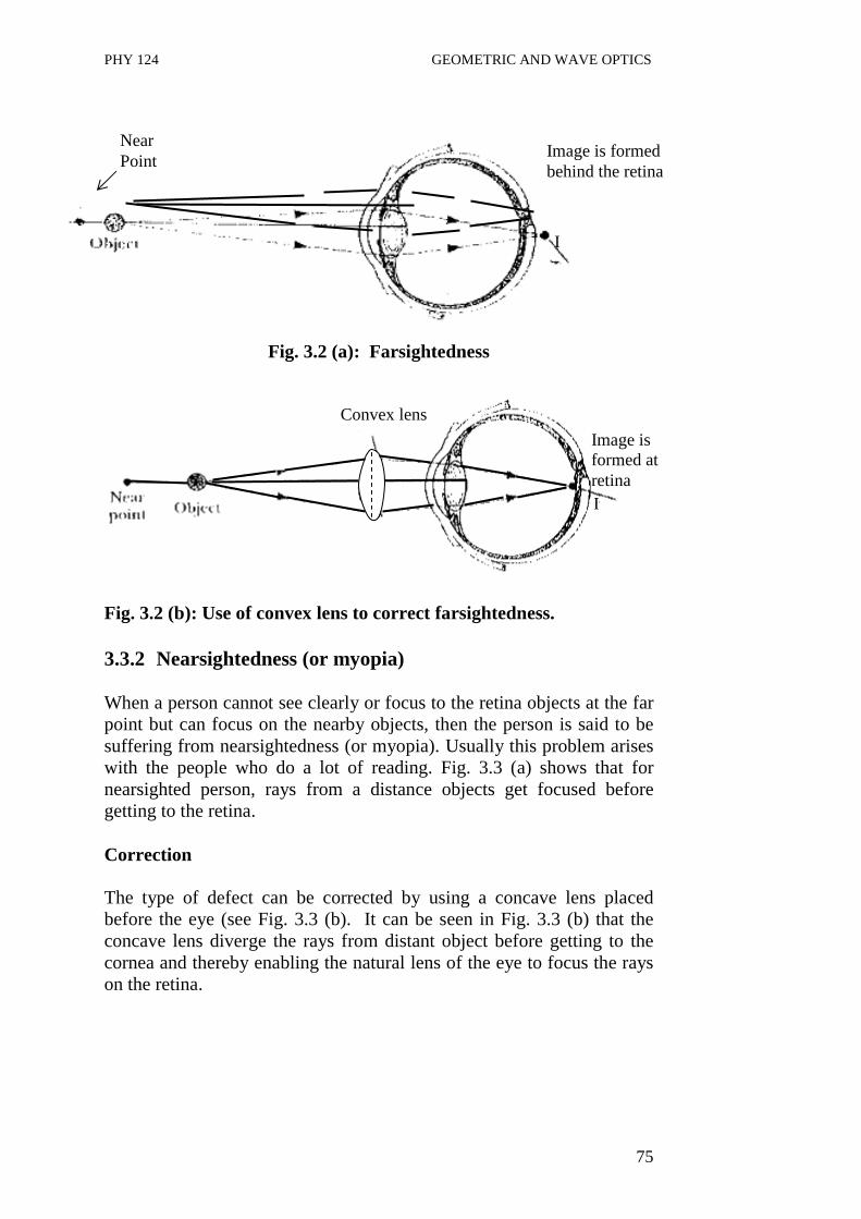
PHY 124 GEOMETRIC AND WAVE OPTICS
75
Fig. 3.2 (a): Farsightedness
Fig. 3.2 (b): Use of convex lens to correct farsightedness.
3.3.2 Nearsightedness (or myopia) When a person cannot see clearly or focus to the retina objects at the far point but can focus on the nearby objects, then the person is said to be suffering from nearsightedness (or myopia). Usually this problem arises with the people who do a lot of reading. Fig. 3.3 (a) shows that for nearsighted person, rays from a distance objects get focused before getting to the retina. Correction The type of defect can be corrected by using a concave lens placed before the eye (see Fig. 3.3 (b). It can be seen in Fig. 3.3 (b) that the concave lens diverge the rays from distant object before getting to the cornea and thereby enabling the natural lens of the eye to focus the rays on the retina.
Near Point
Image is formed behind the retina
I
Convex lens
Image is formed at retina I
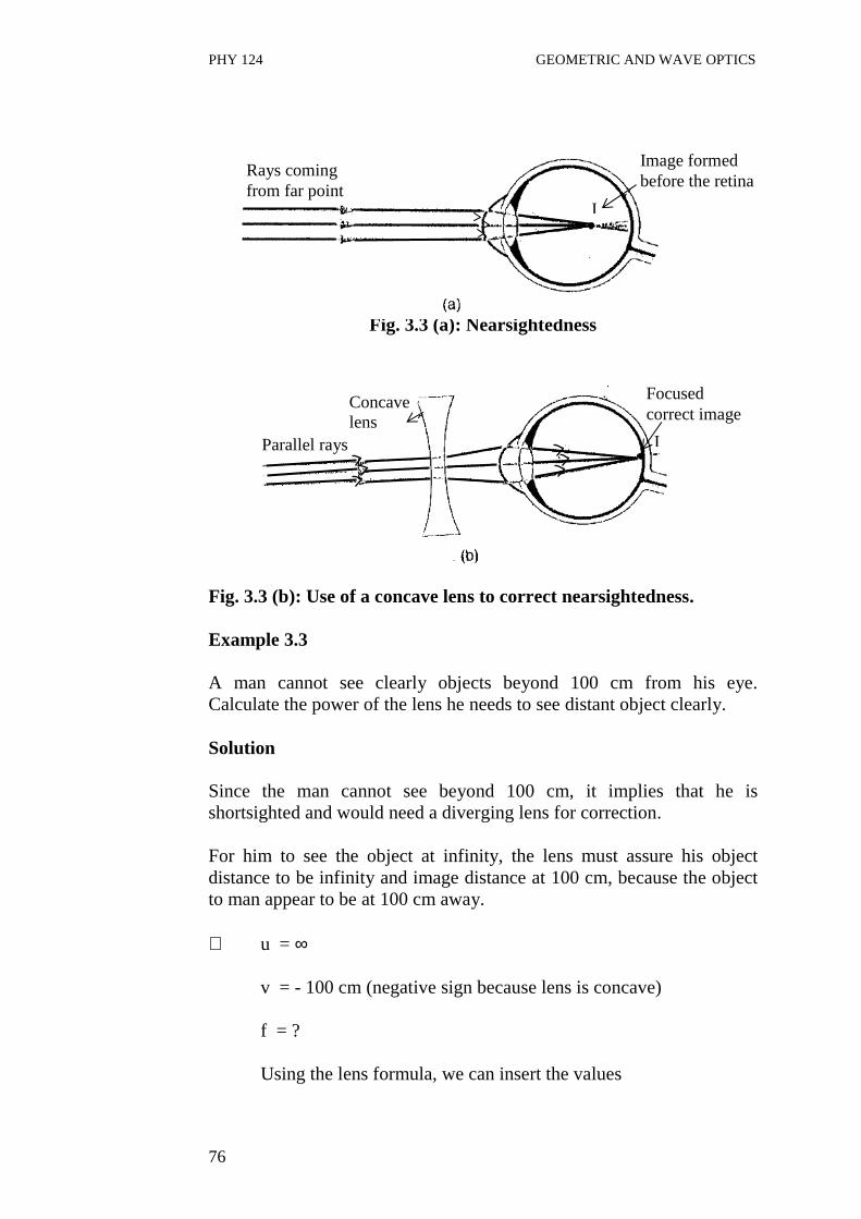
PHY 124 GEOMETRIC AND WAVE OPTICS
76
Fig. 3.3 (a): Nearsightedness
Fig. 3.3 (b): Use of a concave lens to correct nearsightedness. Example 3.3 A man cannot see clearly objects beyond 100 cm from his eye. Calculate the power of the lens he needs to see distant object clearly. Solution Since the man cannot see beyond 100 cm, it implies that he is shortsighted and would need a diverging lens for correction. For him to see the object at infinity, the lens must assure his object distance to be infinity and image distance at 100 cm, because the object to man appear to be at 100 cm away. ∴ u = ∞ v = - 100 cm (negative sign because lens is concave)
f = ? Using the lens formula, we can insert the values
Parallel rays
Concave lens
Focused correct image
I
I
Rays coming from far point
Image formed before the retina
I

PHY 124 GEOMETRIC AND WAVE OPTICS
77
∞+−=+= 1
100
1111
uvf
0100
11 +−=f
f = - 100 cm Therefore, power
= 100
100
− dioptres
= - 1.0 dioptres = - 1.0 D 4.0 CONCLUSION The eye is similar to the camera in many ways. It has a lens, a shutter (iris) and a film (retina). Its mode of image formation is very similar to that of a camera in all respect. The image formed on the retina is always inverted just like the image formed by a camera on a film. The only difference is that the human brain interprets the image and also the lens of the eye is usually adjustable to enable it focus on far or near objects. The ability of the lens to adjust it so if for the purpose is known as accommodation. The power of a lens is usually expressed as the inverse of the focal length. Its unit is diopter. The diopter is represented by D. The two defects of eye are farsightedness (or hyperopia) and nearsightedness (or myopia). In farsightedness, the person is able to see distinctively far away objects but not nearly objects. In this case, light from near objects are focused behind the retina and a convex lens is used to correct these defect. In the case of nearsightedness, the eye is able to see distinctively objects that are near but not those far off. In this case, rays from distant object are focused by the lens before the retina. A concave lens is used to correct this defect.

PHY 124 GEOMETRIC AND WAVE OPTICS
78
5.0 SUMMARY • The eye is similar in form and in operation to the camera. • The image formed by the eye is inverted just like the one formed
on the camera film but it’s interpreted as being correct by the brain.
• Also the shape and consequently the focal length of the normal eye are variable and can therefore focus on near or far object when required. The ability of the eye to do these is known as accommodation.
• One of the major defects of the eye is farsightedness. This defect occurs when light from far objects are focused behind the retina. The defect is corrected by introduction of a convex lens before the eye.
• Another major defect of the eye is nearsightedness. This defect occurs when light from distant object are focused before the retina. The defect is corrected by the introduction of a concave lens before the eye.
6.0 TUTOR-MARKED ASSIGNMENT 1.(a) Calculate the focal length of a lens of power 2.0 D. (b) Explain, how a normal eye produces a sharp image? 2. What are the two defects of vision? How they can be corrected?
Explain with diagram. 7.0 REFERENCES/FURTHER REDINGS Nelkon and Parker. Advance Level Physics. British Library Publication. Kenneth .W. Ford. Basic Physics. Toronto London: Waltham
Massachusetts. Mark .W. Zemansky. College Physics. London: Addison – Wesley. Shortley and Williams. Principles of College Physics. Englewood Cliff
New Jersey: Prentice Hall Inc.

PHY 124 GEOMETRIC AND WAVE OPTICS
79
UNIT 4 OPTICAL INSTRUMENTS CONTENTS 1.0 Introduction 2.0 Objectives 3.0 Main Content
3.1 The Microscope 3.1.1 Simple Microscope in Normal Use 3.1.2 Simple Microscope with Image at Infinity 3.1.3 Compound Microscope 3.1.4 Telescope 3.1.5 The Astronomical Telescope in Normal Adjustment
4.0 Conclusion 5.0 Summary 6.0 Tutor-Marked Assignment 7.0 References/Further Readings 1.0 INTRODUCTION In earlier units, we have studied about reflection and refractions and see how the rays are reflected and refracted. Then, we learnt about lenses and studied that these lenses can be used to converge or diverges the rays from distant objects. These lenses focus light and produce a sharp image. In the last unit, we discussed that how lenses are used to correct the defects of vision. Now the question arises: can we make use of these lenses further? Yes, we can, in the form of microscope, telescope, which you may have come-across in your earlier school physics curriculum. In this unit, we will study about the further use of lenses in optical instruments like microscope and telescope. You will also learn that how the combination of lenses form these optical instruments. The microscope or a magnifier is used to see very tiny objects or to magnify the size of the objects which cannot be seen by naked eyes whereas telescope is used to view the distant object such as planets or other Astronomical objects. The invention of these instruments (i.e. microscope and telescope etc.) has made a great impact on our life. So, now we will study in detail about these two optical instruments and also look how they operate.

PHY 124 GEOMETRIC AND WAVE OPTICS
80
Fig. 4.1: Size of the image on retina, q and angle θθθθ subtended on eye. 2.0 OBJECTIVES After studying this unit you will be able to: • define visual angle and angle of magnification • distinguish between microscope and the telescope • explain how the microscope function • explain how the astronomical telescope functions in normal
adjustment • explain how the astronomical telescope functions when its image
is formed at near point. 3.0 MAIN CONTENT 3.1 The Microscope Before discussing the details of simple microscope, first we briefly discuss about visual angle subtended by an object at the eye. This is because in the optical instruments like telescopes and microscopes, we are concerned with the visual angle. An object NM is placed at some distance from the eye as shown in Fig. 4.1. This object is subtended an angle θ at the eye. The length of the image q formed by the eye is proportional to angle θ subtended at the eye by the object. This angle is called the visual angle. Using the relation Angle = Arc Radius q = pθ ∴q is directly proportional to θ (as p is constant)
θ
P q
M
N
Eye lens K Object
Image formed
θ

PHY 124 GEOMETRIC AND WAVE OPTICS
81
This shows that the visual angle is directly proportioned to apparent size of the object. Optical Instruments such as telescopes and microscopes are designed to increase the visual angle. The resultant effect of this is that the image of the object formed on the retina becomes much bigger than it is when these instruments are not used to view them i.e., image formed on the retina when these instruments are used become much magnified than when they are not used. Now in our next subsections you will learn about simple microscope and compound microscope. First, we will discuss about the simple microscope in normal use and then simple microscope with image infinity. 3.1.1 Simple Microscope (in normal use) M' θθθθ = visual angle
Fig. 4.2: Object move from N to N'
Fig. 4.2 shows that two objects (of different size) MN and M'N' are subtending the same visual angle θ at the eye, therefore appears to be of equal size. But in actual, the objects are of different sizes and object MN is bigger in size.
θ
M
N N'

PHY 124 GEOMETRIC AND WAVE OPTICS
82
eye
Fig. 4.3: (a) The visual angle α Fig. 4.3 (b): α ' is the visual angle without microscope subtended after using the
microscope A simple microscope in normal use means that the image is formed at the near point as shown in Fig. 4.3 above. Here h is the length of the object viewed at near point (it means at D). The visual angles subtended are α (in radian) and α′ (in radian). The α′ is the increased angle when the simple microscope is used to view the object given in Fig 4.3 (b). As you can see, magnified image is obtained which is erect and the distance of image is equal to D. The angular magnification is maximum when the image is at the near point of the eye. The angular magnification in terms of visual angle is
M = α′ ………………….(4.1) α
Now, the values of α and α′ can be obtained from Fig. 4.3 (a) and (b).
α′ = h′/D and α = h/D
Therefore Eq. 4.1 becomes
===u
v
h
h
Dh
DhM
`` …. (4.2)
Here u is the object distance and v is the image distance. Since you know that
fvu
111 =+
D α
h
D
h'
α'

PHY 124 GEOMETRIC AND WAVE OPTICS
83
On multiplying the above Eq. by v and on rearranging the terms, we get
1−=f
v
u
v
Or
1−−=f
D
u
v
+−= 1
f
D
u
v
+−==′∴ 1
f
D
u
v
h
h ……… (4.3)
Substituting Eq. (4.3) in Eq. (4.2), we get the expression
+−= 1
f
DM
Numerically, magnification can be written as
+= 1
f
DM ………. (4.4)
Eq. (4.4) gives the angular magnification of a microscope in normal use and the negative sign is an indication that the final image is virtual. Further, it can be seen that for higher angular magnification, a lens of short focal length is needed. You know that the eye has the tendency to focus on an image formed anywhere between the near point and infinity by a simple microscope. So, now you will study another case, when the image is formed at infinity.
3.1.2 Simple Microscope (with Image at Infinity) You know that the eye has the tendency to focus on an image formed anywhere between the near point and infinity by a simple microscope.

PHY 124 GEOMETRIC AND WAVE OPTICS
84
Fig. 4.4 (a) A simple microscope is an instrument which is used to see very small objects. As discussed in the earlier sub-section (section 3.1.1) that, when it is in normal use, the image is formed at D (least distance of distinct vision)
(b) Fig. 4.4: (a) Visual angle when the object is placed at the distance D,
(b) Visual angle formed when the object is placed near the focal point.
A simple microscope with the image formed at infinity means that the eye must be accommodated to bring the image to infinity as shown in Fig. 4.4 above. Where f is the focal length of a lens. The magnification M can be defined as
f
DM
f
D
Dh
fh
M
=∴
==′=αα
……(4.5)
Eq. (4.5) gives an angular magnification with a microscope having a single lens. Magnification can be further increased by using one or two additional lenses. So, now we will discuss about the compound microscope.
D α
h
infinity
f

PHY 124 GEOMETRIC AND WAVE OPTICS
85
3.1.3 Compound Microscope A simple microscope in normal adjustment has its magnification numerically as
1+=f
DM
A decrease in f implies an increase in angular magnification. But in practice, it is difficult to obtain a very small f. Therefore two lenses can be used to increase angular magnification. This two lens microscope is known as the compound microscope as shown in Fig. 4.4 below.
(a)
(b)
Fig. 4.4 (a) Compound microscope (b) compound microscope in normal use
A compound Microscope in normal use means that the final image is formed at the near point. The details of the image formation are discussed below. The compound microscope essentially consists of two convex lenses of focal length f1 and f2 in which one of the lenses (of focal length f1) is the objective lens and the second lens (of focal length f2) is the eye piece. The objective lens is placed near the object being viewed while the eyepiece is the lens near the eye as shown in Fig. 4.4(a). fo is the focus of the objective lens and the fe is the focus of the eyepiece. h1 is the height of the image formed by the objective and finally we get image h2 by an eyepiece.
D α
D
f1
u Eyepiece lens
Eye h1
fe •
Objective lens
f2
v
object • fo
α
h2

PHY 124 GEOMETRIC AND WAVE OPTICS
86
The lenses are arranged such that their separation is less than f1 + f2. As such the image of the object formed by the objective lens is located from the second lens at a distance less than the focal length of the second lens. Thus the image of the first image formed by the second lens must be virtual and magnified. Consequently the final image formed is several times larger than the object to the observer.
Now, the formula of angular magnification for compound microscope is given by
−
+=∴ 11
12 f
v
f
DM ….. (4.6)
Therefore, from Eq. (4.6), it can be noted that M is large for small f1 and f2. It means that if the focal lengths of the objective lens and eyepiece lens are both small, angular magnification will be high. After discussing about microscope, now you will learn about the telescopes in the next subsection. Telescopes are the instruments used to see distant objects or heavenly bodies like stars, planets etc.
3.1.4 Telescope The angular magnification of a Telescope is defined as the ratio:
αα ′=M …..( 4.7)
Where α is the visual angle subtended by the distance object at the unaided eye and α′ is the angle subtended at the eye by its final image when telescope is used. There are different types of telescope one of which is the astronomical telescope. Now, we will discuss in the succeeding section first the Astronomical Telescope in normal Adjustment. 3.1.5 The Astronomical Telescope in Normal Adjustment Astronomical telescope like compound microscope, consist of two lenses: objective and eyepiece. The objective is of large focal length and eyepiece is of short focal length closer to the image. f1 is the focal length of the objective while f2 is the focal length of eyepiece.

PHY 124 GEOMETRIC AND WAVE OPTICS
87
Fig. 4.5: An Astronomical Telescope in normal adjustment.
The parallel rays are collected by the objective lens O and an image h is formed. Final image is formed at infinity (∞). In normal adjustment the two foci f1 and f2 coincides and it therefore implies that the distance between the two lenses is f1 + f2 . If α is the angle subtended by the unaided eye and α′ is the angle subtended by the aided eye. Then, since α and α′ are small the angular magnification of the telescope is
1
2
fh
fh
M =′=αα
2
1
f
fM = ……( 4.8)
So from Eq. 4.8, the angular magnification is the ratio of focal length of objective to the focal length of eyepiece. For high angular magnification the eyepiece should have a small focal length and objective should have high focal length. Example 4.1 An astronomical telescope consists an objective of focal length 100 cm and an eyepiece of focal length 4 cm. Calculate the angular magnification of the telescope and also determine the distance between the two lenses.
α1
Image at infinity
fo h
α
α
f1 f2
f2 f1
objective Eyepiece piece
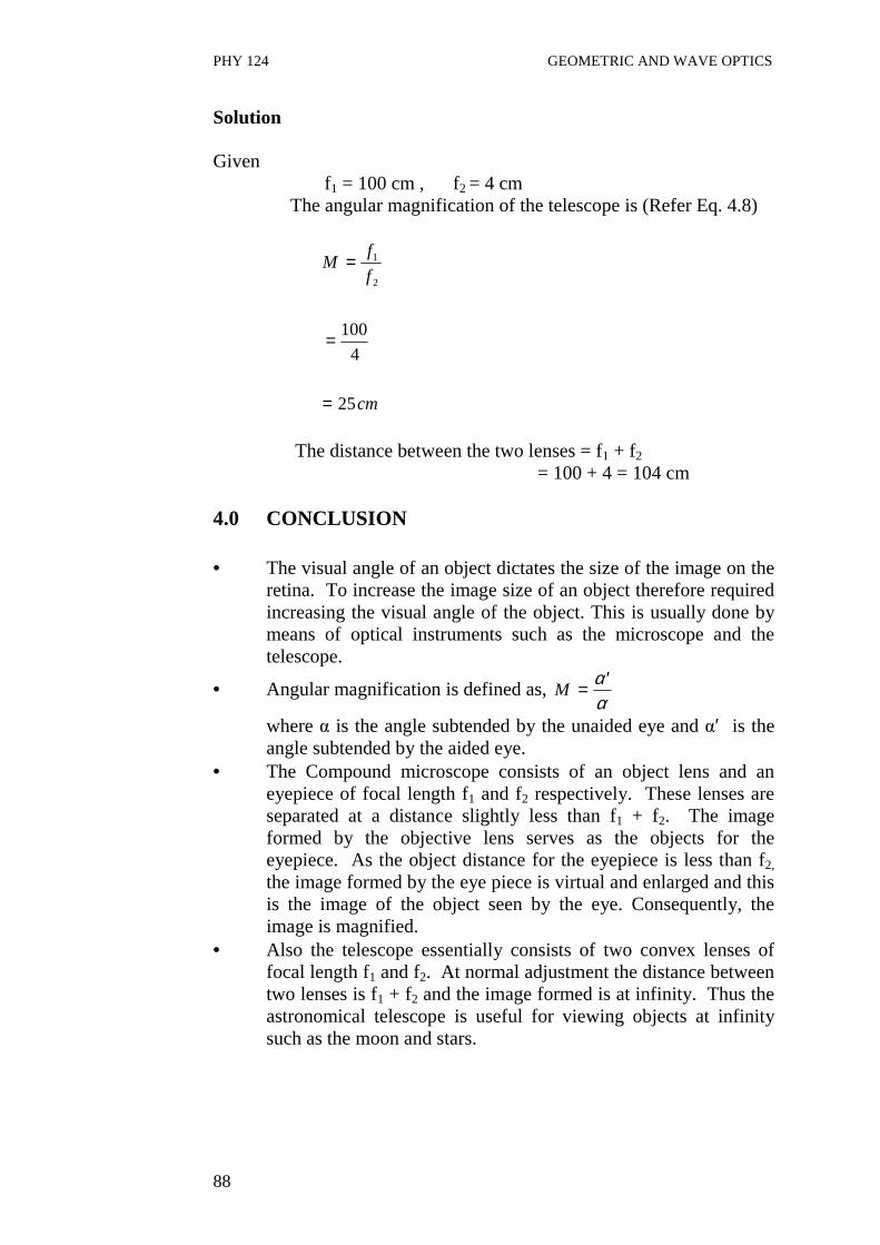
PHY 124 GEOMETRIC AND WAVE OPTICS
88
Solution Given
f1 = 100 cm , f2 = 4 cm The angular magnification of the telescope is (Refer Eq. 4.8)
cm
f
fM
25
4
100
2
1
=
=
=
The distance between the two lenses = f1 + f2 = 100 + 4 = 104 cm 4.0 CONCLUSION • The visual angle of an object dictates the size of the image on the
retina. To increase the image size of an object therefore required increasing the visual angle of the object. This is usually done by means of optical instruments such as the microscope and the telescope.
• Angular magnification is defined as, αα ′=M
where α is the angle subtended by the unaided eye and α′ is the angle subtended by the aided eye.
• The Compound microscope consists of an object lens and an eyepiece of focal length f1 and f2 respectively. These lenses are separated at a distance slightly less than f1 + f2. The image formed by the objective lens serves as the objects for the eyepiece. As the object distance for the eyepiece is less than f2,
the image formed by the eye piece is virtual and enlarged and this is the image of the object seen by the eye. Consequently, the image is magnified.
• Also the telescope essentially consists of two convex lenses of focal length f1 and f2. At normal adjustment the distance between two lenses is f1 + f2 and the image formed is at infinity. Thus the astronomical telescope is useful for viewing objects at infinity such as the moon and stars.

PHY 124 GEOMETRIC AND WAVE OPTICS
89
5.0 SUMMARY • The magnitude of the image of an object formed on the retina is
determined by its visual angle. • Angular magnification is achieved by using optical instruments
such as the microscope and telescope. • The microscope has an objective lens and an eye-piece, the two
lenses are arranged in such a way that their separation is slightly less than f1 + f2.
• In the microscope the image formed by the objective lens falls between the second lens and its near principal focus. As such, the final image formed by the eyepiece is virtual and enlarged. Consequently, the final image seen by the eye is much more magnified than the object.
• The telescope also consists of an objective lens and eyepiece of focal lengths f1 and f2 respectively. At normal adjustment, the separation of the two lenses equals f1 + f2 and the final image formed is at infinity. Hence such telescope is good for viewing very distant (astronomical) objects at infinity.
6.0 TUTOR-MARKED ASSIGNMENT Calculate the angular magnification of a magnifying glass of focal length 7 cm. Also, determine the object distance. 7.0 REFERENCES/FURTHER REDINGS Nelkon and Parker. Advance Level Physics. British Library Publication. Kenneth .W. Ford. Basic Physics. Toronto London: Waltham
Massachusetts. Mark .W. Zemansky. College Physics. London: Addison – Wesley. Shortley and Williams. Principles of College Physics. Englewood Cliff
New Jersey: Prentice Hall Inc.

PHY 124 GEOMETRIC AND WAVE OPTICS
90
UNIT 5 OTHER TYPES OF TELESCOPES CONTENTS 1.0 Introduction 2.0 Objectives 3.0 Main Content
3.1 The Eye Ring 3.2 Astronomical Telescope with Image Formed at Near Point 3.3 The Terrestrial Telescope 3.4 The Reflective Telescope
4.0 Conclusion 5.0 Summary 6.0 Tutor-Marked Assignment 7.0 References/Further Readings 1.0 INTRODUCTION In the last unit, we discussed the different optical instruments like compound microscope and telescope. Both these optical instruments consist of two lenses, objective and an eyepiece, of different focal length. The astronomical telescope is used primarily for viewing objects at very large distances or astronomical bodies like stars and the moon. On the other hand, the compound microscope is used to magnify the size of the object. So, in these optical instruments, objective lens collects light rays from the object which is bounded by the perimeter of the objective lens. Therefore the lens acts as a stop to the light rays from the object. As the eyepiece is a lens, the objective lens also serves as an object to it. The image of the objective lens formed by the eyepiece is called the eye-ring. When the observer places the eye at the eye-ring of the instrument (i.e. compound microscope or telescope) he receives maximum light from the objective and consequently from the object being viewed. In this unit, you will learn the principle and theory behind the formation of eye-ring. Also in this unit you will study about two other types of telescopes. One of them is another type of astronomical telescope known as the reflector telescope and second one is primarily used to view distant objects on earth and this type of telescope is known as the terrestrial telescope.

PHY 124 GEOMETRIC AND WAVE OPTICS
91
2.0 OBJECTIVES After studying this unit you should be able to: • define and explain the eye-ring • distinguish between astronomical and terrestrial telescope • distinguish between reflector and the terrestrial telescope • explain the operation of the terrestrial telescope • explain the operation of the reflector telescope. 3.0 MAIN CONTENT 3.1 The Eye Ring
Fig. 5.1: Formation of an eye-ring In the Fig. 5.1 as shown above, the rays are refracted from the boundary of objective lens to make the image at f0 in normal adjustment. These rays again refracted from the boundary of eye-lens and an eye-ring ab is formed. The eye-ring ab is the image of the object lens AB formed at the eyepiece. It is the best position of the eye when using the telescope because maximum amount of light enters the object lens from outside thereby creating a wide field of view. At a distance closer to the eye-lens than the eye-ring, no further improvement in view is obtained. Using the lens equation for the above figure, one can obtained the value of distance v from the eye-ring as
221
1
)(
11
fffv=
++
On rearranging the terms of the equation, we get
)( 211
2 fff
fv += ………….. (5.1)
r
Object lens Eye lens
Eye-ring
f1+f2 B
a
fo b
A
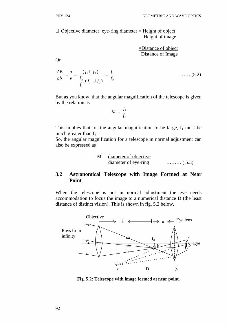
PHY 124 GEOMETRIC AND WAVE OPTICS
92
∴ Objective diameter: eye-ring diameter = Height of object Height of image
=Distance of object Distance of Image
Or
2
1
211
2
21
)(
)(
f
f
fff
fff
v
u
ab
AB =+
+== …… (5.2)
But as you know, that the angular magnification of the telescope is given by the relation as
2
1
f
fM =
This implies that for the angular magnification to be large, f1 must be much greater than f2 So, the angular magnification for a telescope in normal adjustment can also be expressed as
M = diameter of objective diameter of eye-ring ……… ( 5.3) 3.2 Astronomical Telescope with Image Formed at Near
Point When the telescope is not in normal adjustment the eye needs accommodation to focus the image to a numerical distance D (the least distance of distinct vision). This is shown in fig. 5.2 below.
Fig. 5.2: Telescope with image formed at near point.
D
f1 u Eye lens
Eye h
fo
Rays from infinity
Objective
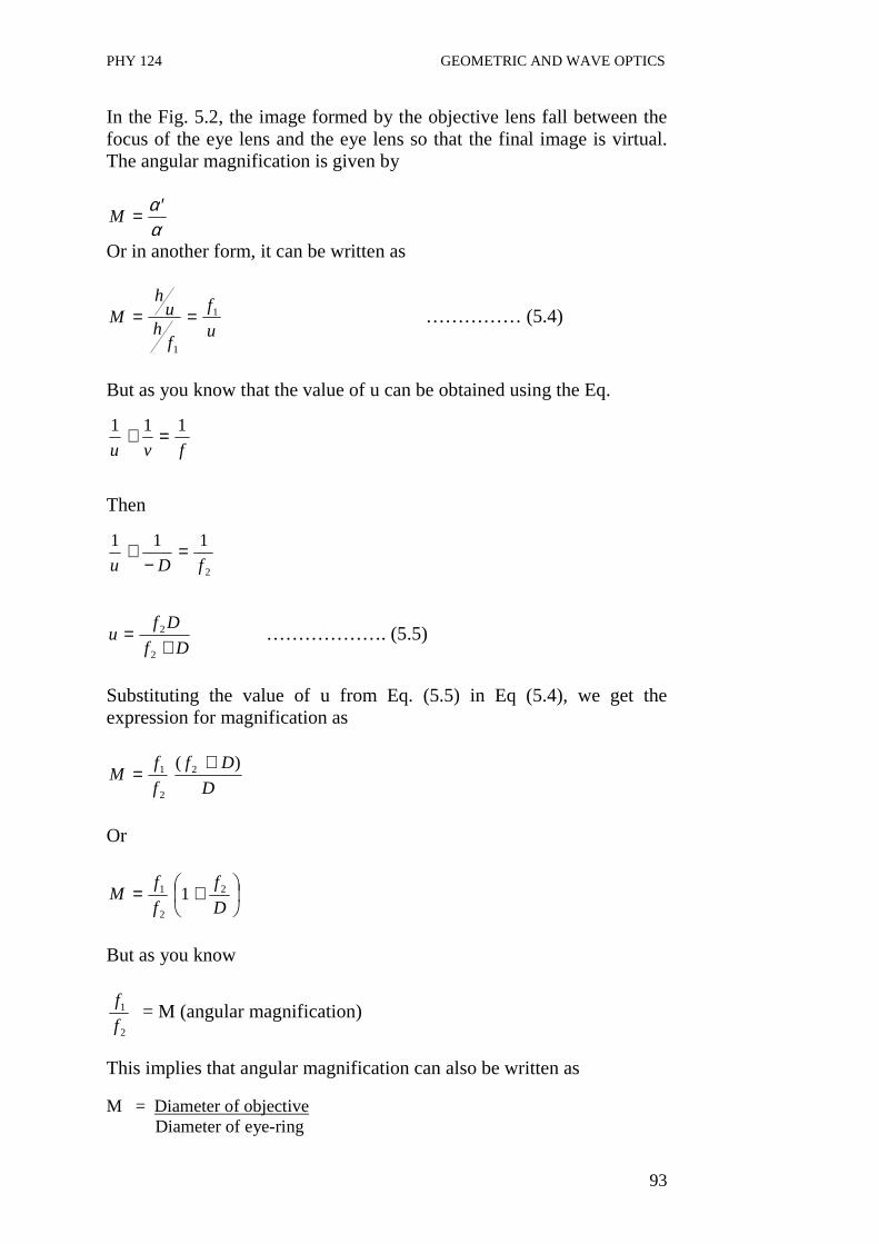
PHY 124 GEOMETRIC AND WAVE OPTICS
93
In the Fig. 5.2, the image formed by the objective lens fall between the focus of the eye lens and the eye lens so that the final image is virtual. The angular magnification is given by
αα ′=M
Or in another form, it can be written as
u
f
fh
uh
M 1
1
== …………… (5.4)
But as you know that the value of u can be obtained using the Eq.
fvu
111 =+
Then
2
111
fDu=
−+
Df
Dfu
+=
2
2 ………………. (5.5)
Substituting the value of u from Eq. (5.5) in Eq (5.4), we get the expression for magnification as
D
Df
f
fM
)( 2
2
1 +=
Or
+=D
f
f
fM 2
2
1 1
But as you know
2
1
f
f = M (angular magnification)
This implies that angular magnification can also be written as M = Diameter of objective Diameter of eye-ring
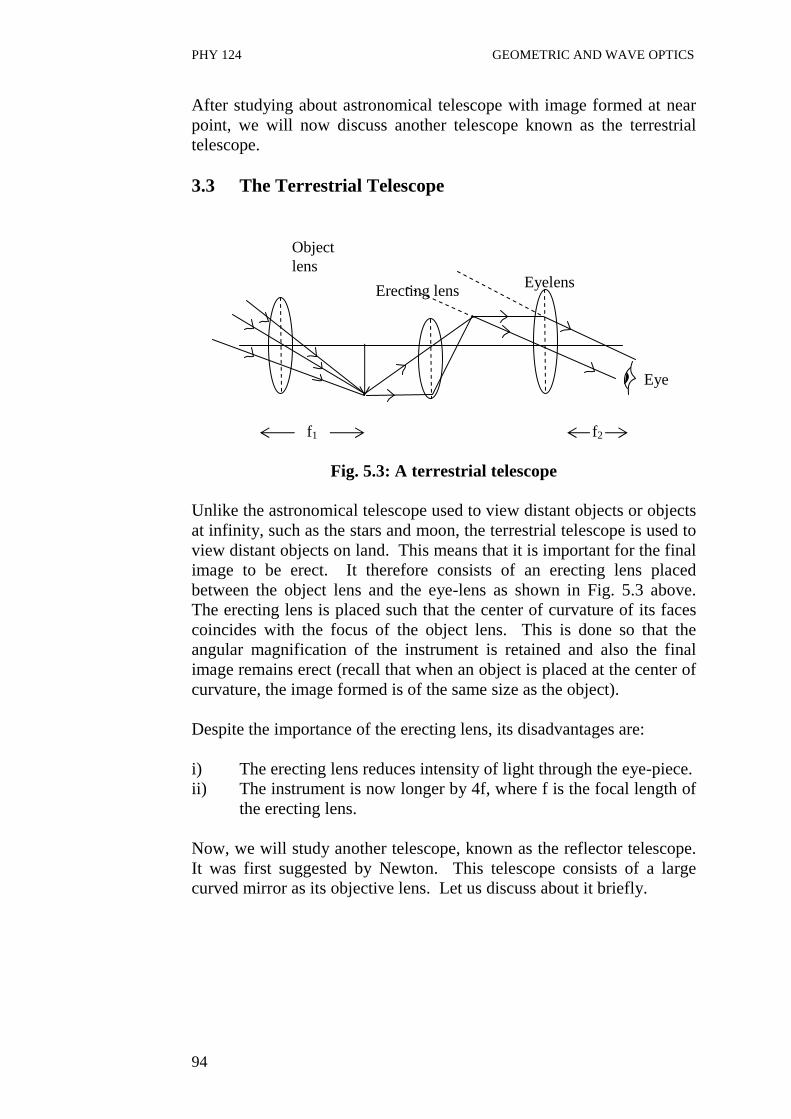
PHY 124 GEOMETRIC AND WAVE OPTICS
94
After studying about astronomical telescope with image formed at near point, we will now discuss another telescope known as the terrestrial telescope. 3.3 The Terrestrial Telescope
Fig. 5.3: A terrestrial telescope Unlike the astronomical telescope used to view distant objects or objects at infinity, such as the stars and moon, the terrestrial telescope is used to view distant objects on land. This means that it is important for the final image to be erect. It therefore consists of an erecting lens placed between the object lens and the eye-lens as shown in Fig. 5.3 above. The erecting lens is placed such that the center of curvature of its faces coincides with the focus of the object lens. This is done so that the angular magnification of the instrument is retained and also the final image remains erect (recall that when an object is placed at the center of curvature, the image formed is of the same size as the object). Despite the importance of the erecting lens, its disadvantages are: i) The erecting lens reduces intensity of light through the eye-piece. ii) The instrument is now longer by 4f, where f is the focal length of
the erecting lens. Now, we will study another telescope, known as the reflector telescope. It was first suggested by Newton. This telescope consists of a large curved mirror as its objective lens. Let us discuss about it briefly.
Object lens
Erecting lens
Eye
f2 f1
Eyelens

PHY 124 GEOMETRIC AND WAVE OPTICS
95
The Reflector Telescope
Fig. 5.4: Newton Reflector Telescope Fig. 5.4 refers to a reflector telescope. An astronomical telescope with lens as its objective is called a refractor telescope while a reflector telescope has a large curved mirror as its objective as shown in Fig. 5.4 above. It consists of a parabolic mirror of large size as its objective. Because of its large size, the mirror collects large amount of light from distant planets and brought to focus to be photographed. The advantages of using this kind of telescope are: i) It has a large angular magnification. Recall the expression
M = 2
1
f
f
Where, f1 is the focal length of the objective. As it is difficult to manufacture a lens with very large focal length, there is a limitation to the magnification. This can be achieved with a mirror; it is preferable to use a very large mirror as the objective.
ii) The telescope is free from chromatic aberration caused by an objective lens.
iii) There will be no loss of light due to absorption and reflection of light as on the surface of a lens.
iv) The large diameter of the objective increases the resolving power of the telescope.
The resolving power of a telescope (the two distant objects just seem separated) is given by
θλ1
22.1== D
P ….. (5.8)
Here, θ is the smallest angle which is subtended at the telescope by two distant objects which can just be seen separated. The
Eyepiece
Light rays
Plane mirror
Objective

PHY 124 GEOMETRIC AND WAVE OPTICS
96
other symbols used here are: D is the diameter of the objective lens and λ is the mean wavelength of light from the object. From Eq. (5.8), it can be observed that θ is inversely proportional to resolving power of a telescope. If the value of θ is smaller, then the resolving power is greater. The value of θ does not depend upon the focal length of the objective but only depends on its diameter.
4.0 CONCLUSION The eye-ring is the image of the objective lens formed at the eyepiece. That represents the position at which the observer eyes should be placed in order to obtain the maximum light from the objective lens. Under this condition, the angular magnification obtained from the image formed is
M = Diameter of objective Diameter of eye-ring The other type of telescope studied in this unit is the terrestrial telescope. This type of telescope is used mainly for viewing distant object on the earth surface. The astronomical telescope has an additional convex lens whose sole purpose is to make the final image appear erect. The refractor telescope is another type of astronomical telescope. It has a very large concave mirror as its objective rather than a lens. The advantages of this type of telescope are: i) It has a large angular magnification; ii) It is free from chromatic aberration; iii) It is not associated with loss of light due to absorption and
reflection of light on the surface of lens; and iv) It has better resolving power. 5.0 SUMMARY • The eye-ring is the image of the objective lens at the eyepiece. • The angular magnification associated with eye-ring is
Diameter of objective Diameter of eye-ring
• The terrestrial telescope is a telescope used mainly for viewing distant objects on the earth surface.
• Te terrestrial telescope has an additional lens which makes the final image erect
M =

PHY 124 GEOMETRIC AND WAVE OPTICS
97
• The introduction of this additional lens in the terrestrial telescope causes a reduction in intensity of light available to the eye thereby making the image dull.
• The reflector telescope is another type of astronomical telescope, however unlike the normal telescope its objective is a large concave mirror.
• The advantages of the reflector telescope over the normal astronomical telescope are its large angle of magnification, its better resolving power and its freedom from chromatic aberration.
• A large mirror as objective in reflector telescope reduces loss of light by lens telescope
6.0 TUTOR-MARKED ASSIGNMENT 1. Determine the resolving power of a telescope, if the objective of
a telescope has a diameter of 300mm. The mean wavelength of the light from stars is 6 x 10⁻⁷ m.
2. Explain the term eye-ring of a telescope. Show with a ray diagram, how the eye ring is formed in an astronomical telescope.
3.(a) What is meant by angular magnification of an optical instrument? (b) Calculate the angular magnification of a simple astronomical
telescope in normal adjustment which has an objective of focal length 120 cm and an eyepiece of 6 cm.
7.0 REFERENCES/FURTHER READINGS Nelkon and Parker. Advance Level Physics. British Library Publication. Kenneth .W. Ford. Basic Physics. Toronto London: Waltham
Massachusetts. Mark .W. Zemansky. College Physics. London: Addison – Wesley. Shortley and Williams. Principles of College Physics. Englewood Cliff
New Jersey: Prentice Hall Inc.
PHY 124 GEOMETRIC AND WAVE OPTICS
98
MODULE 3 INTERFERENCE AND POLARIZATION OF LIGHT
Unit 1 Interference Unit 2 Interference in Thin Films and Air Wedge Unit 3 Newton’s Rings and Interference in Thin Films Unit 4 Polarization of Light Unit 5 Laws and Application of Polarization UNIT 1 INTERFERENCE CONTENTS 1.0 Introduction 2.0 Objectives 3.0 Main Content
3.1 Wave Nature of light 3.2 Coherent Sources 3.3 Interference 3.4 Optical Path 3.5 The Young’s Double Slit Experiment 3.6 Fringe Separations
4.0 Conclusion 5.0 Summary 6.0 Tutor-Marked Assignment 7.0 References/Further Readings 1.0 INTRODUCTION You know that light travels as a stream of particles and also in the form of waves. Light is wave motion. However light is an electromagnetic wave, which vibrates at right angle to its direction of propagation while sound energy is a mechanical wave, which vibrates, in the same direction as the direction of propagation. In other words, light wave is a transverse wave of electromagnetic origin and sound is a longitudinal wave of mechanical origin. But here, we will study a very important characteristic of wave motion that is the phenomena of interference. When two beams of light superposed, there intensity varies from point to point between maxima and minima in the region of superposition. This phenomenon is called interference. It means at certain point, the intensity exceeds the sum of intensities in the beams and on the other point, the intensity weaken or may be zero. Hence, we obtain bright and dark fringes on a screen.
PHY 124 GEOMETRIC AND WAVE OPTICS
99
In this unit, we discuss the coherent sources and the use of path difference for constructive and destructive interference. The interference pattern produced by waves originating from two point sources is also discussed here. You will also learn about the interference produced in Young’s two-slit experiment. In the next unit, you will study how interference takes place in thin films and Air wedge. 2.0 OBJECTIVES After studying this unit, you should be able to: • explain the wave nature of light • explain what coherent sources are • define the interference and its types • define optical path • explain the conditions for interference • describe Young’s double slit experiment • express the fringe width in terms of wavelength of light • solve problems involving Young’s experiment. 3.0 MAIN CONTENT 3.1 Wave Nature of Light Even though in units 1 – 10, we have considered light in a form of rays. It has been found that in reality light is a form of wave traveling in straight lines represented by the rays. These waves are different from sound waves because sound waves are longitudinal while light waves vibrate perpendicularly to the direction of propagation. Also sound wave is a mechanical wave, whereas light is an electromagnetic wave. The human eye can see light of wavelength which lies between 450 x 10-9m and 750 x 10-9m. This range of wavelength is known as the visible range of electromagnetic spectrum. Some electromagnetic waves have shorter wavelength that visible light, while others have longer wavelength then visible light. These invisible electromagnetic waves differ from visible light only in terms of wavelength and in the ways by which they are produced. Before studying interference in detail, it is necessary to familiarize with the terms like coherent sources used in interference phenomena. Now we shall first discuss coherent sources.

PHY 124 GEOMETRIC AND WAVE OPTICS
100
3.2 Coherent Source
Let there are two interfering waves (light waves). If these interfering waves are produced randomly, it means that they are out of phase with each other (or there is a continual change of phase), then such sources of interfering waves are known as incoherent source.
Coherent sources are the sources which must emit light waves of
(i) same frequency or wavelength and (ii) a constant phase difference or which are always in phase with
each other (and they must be traveling in the same or nearly the same direction).
So, now in the next section we discuss in details the phenomena of interference produced by two coherent sources.
3.3 Interference
Consider two waves originated from two coherent sources of light A and B, of the same frequency (or wavelength) travel in the same direction and having a constant phase difference with the passage of time. The resultant intensity of light do not distributed uniformly in space. Therefore, non-uniform distribution of the light intensity due to combined effect (superposition) of two waves is called interference. Usually, it is found that at some points the intensity of light is maximum and on the other points, the intensity of light is minimum. Refer to Fig. 1.1. Fig. 1.1: Point of constructive interference (T) and destructive
interference (M). Now, let us discuss the different types of interference patterns. The interference is of two types: (a) constructive interference (b) destructive interference.
P M
T
K Q
Screen

PHY 124 GEOMETRIC AND WAVE OPTICS
101
(a) Constructive Interference Constructive interference occurs when the effect of two interfering waves is additive at the point of interest. At these points, intensity becomes maximum. The resultant vibration at the point is obtained by adding them (their amplitudes). A bright ‘band’ of light is obtained at these points. That is, they add up to give something bigger than contribution from either source of the two sources.
Suppose we consider two coherent source A and B that are exactly in phase as shown in Fig. 1.2, the interference effect at an equidistant point T is constructive, and obtained by adding the displacement of the individual wave at the point. Time →
(a) Wave from source A
Time →
(b) Wave from source B
Time → Fig. 1.2: Constructive Interference: (a) wave from source A (b) wave
from source B (c) Resultant of two waves. In general constructive interference would occur if the path difference, d, at any point P is multiples of zero or whole number wavelength that is
d = nλ
Where n = 0, 1, 2, ……… so on. …………….. (1.1)
Displacement
Displacement
Displacement
Resultant Wave

PHY 124 GEOMETRIC AND WAVE OPTICS
102
On the other hand destructive interference occurs when the net effect at the point of interest, is the effect of one source minus the effect of the other source. Now you will learn about destructive interference in detail. (b) Destructive Interference
The destructive interference occurs at some point where the intensity is minimum. This is the situation in which the interference effects is smaller than that produced by the individual waves. Refer to fig. 1.3. At these points, a dark band of light is obtained.
The path difference d for constructive interference can be given by the expression
d=QM – PM = λ
+2
1n …………… (1.2)
where n = 0, 1, 2, 3, ……… so on.
displacement time → displacement
time →
Fig.1.3: Graphical representation of Destructive interference
3.4 Optical Path Consider a medium of refractive index µ and its thickness is t. A light ray is traveling from a point O (in air) to another point A (in air) through a medium which is introduced in between this ray. So the light ray partly travels in air and partly in a medium introduced between as illustrated in Fig. 1.4. In interference phenomena, the optical paths of the coherent light rays are found. The product of the refractive index µ and the path length t is called optical path in the medium.
Resultant (zero)
Wave from A
Wave from B

PHY 124 GEOMETRIC AND WAVE OPTICS
103
Fig. 1.4: Optical path
Optical path = µt When a glass slab is introduced between a ray from O to A, then the expression for optical path is given by Optical path = (d-t) + µt
=d + (µ-1) t ……… (1.3) This shows that the effect of introducing a material of thickness t, refractive index µ is increased the optical path by (µ - 1) t. In other words, the air path OA is increased by an amount (µ - 1)t due to the introduction of the plate of material of refractive index µ and thickness t. Young had first demonstrated the interference of light. In the following section, we will discuss the interference produced in the Young two-slit experiment. 3.5 The Young’s Double slit experiment
Fig. 1.5: Young’s double slit experiment Two slit A and B are illuminated by the same monochromatic source of light S. This ensures that the wave leaving A and B are coherent. It was Thomas Young who first observed that if a transparent screen is placed
d
O A
t
Medium with refractive index µ
O
Y
P
Bright band of fringes
Screen
A
B
Source of monochromatic light ↓
S

PHY 124 GEOMETRIC AND WAVE OPTICS
104
parallel to AB, band of bright and dark images (fringes) would be formed in the region where the beams overlap. At O, along the perpendicular bisector of AB, the waves due to A and B are in phase. Hence, a bright band or fringe is formed. This is because the two light wave coming from A and B would have traveled the same distance at the point O. Bright and dark bands are subsequently formed on either side of O. The bright bands occur where d = n λ where n = 0, 1, 2, 3, …. i.e. constructive interference takes place.
On the other hand the dark bands are formed where d =
+2
1nλ .
These conditions of dark and bright fringes have been discussed earlier also. These alternate bright and dark bands are known as interference fringes. At point O, the path difference is zero. 3.6 Fringe Separations In this section you will see that the thickness Y between two adjacent bright or dark fringes and a is the distance between the slits A and B. D is the distance of the slit from the screen and the wavelength of the monochromatic light is λ. Refer to Fig. 1.6.
Fig. 1.6: The geometry of Young’s experiment. In Fig.1.6, P is the position of the nth bright fringe, then the path difference at that point P is given by
M λn
λ B
A
a
θ θ
D
N
P
O
Xn
tan θ = D
X
B
P n=
sin θ = a
n
H
P λ=
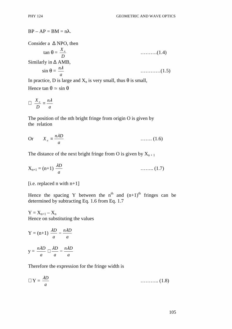
PHY 124 GEOMETRIC AND WAVE OPTICS
105
BP – AP = BM = nλ. Consider a ∆ NPO, then
tan θ = D
X n ……….(1.4)
Similarly in ∆ AMB,
sin θ = a
nλ …………(1.5)
In practice, D is large and Xn is very small, thus θ is small,
Hence tan θ ≃ sin θ
∴ a
n
D
X n λ=
The position of the nth bright fringe from origin O is given by the relation
Or a
DnX n
λ= ……. (1.6)
The distance of the next bright fringe from O is given by Xn + 1
Xn+1 = (n+1) a
Dλ …….. (1.7)
[i.e. replaced n with n+1] Hence the spacing Y between the nth and (n+1)th fringes can be determined by subtracting Eq. 1.6 from Eq. 1.7 Y = Xn+1 – Xn Hence on substituting the values
Y = (n+1) a
Dn
a
D λλ −
y = a
Dn
a
D
a
Dn λλλ −+
Therefore the expression for the fringe width is
∴Y = a
Dλ ……….. (1.8)

PHY 124 GEOMETRIC AND WAVE OPTICS
106
Therefore it can be found from Eq (1.8) that the fringe width varies directly proportional to D and λ and inversely proportional to the distance between the slits a. Hence using the expression in Eq. 1.8, one can measure the wavelength of light easily. Example 1.1 Young’s experiment is performed with sodium light of wavelength of 589nm. Fringes are measured carefully on a screen 100 cm away from the double slit and the center of the 20th fringe is found to be 11.78nm from the axis. Determine the separation of the two slit. Solution Data Given: n = 20, D = 1m, and λ = 589 X 10-9m ∴ The distance of the 20th fringe X20 = 11.78 x 10⁻³m Using the Eq. 1.8
Xn = a
Dnλ
On substituting the values and rearranging the terms, we get
Or a = 3
20 1078.11
1.0 x 9-10 x 589 x 20−=
xX
Dnλ
∴a = 1.0 nm Example 1.2 Using red light, state the effect of the following procedure on the appearance of the fringes. (a) The separating of the slit is decreased. (b) The source slit is moved closed to the two slits. (c) The screen is moved closer to the slit. (d) Blue light is used in place of red light.
a
S D

PHY 124 GEOMETRIC AND WAVE OPTICS
107
(e) One of the slit is covered up. (f) The source slit is made wider. Solution
(a) Since Y = a
Dλ
Then the separation of the fringes would increase if a slit separation is decreased
(b) The fringes would appear brighter but their separation Y would
not change
(c) Since Y = a
Dλ
If the screen’s distance D is reduce, the separation of the fringes Y would also decrease.
(d) Replacing the light source with blue light instead of red is equivalent to changing the wavelength of light used. The wave length of red light is longer than that of blue light. Therefore the separation of the fringe would decrease because.
Y = a
Dλ
as λblue < λred
(e) When one of the two slit is covered up, the fringes would disappear because there would be no interference.
(f) If the source slit is made wider, the fringes would overlap and
become blurred because the edge of each opening would behave as a source on its own, as shown in Fig. 1.7.
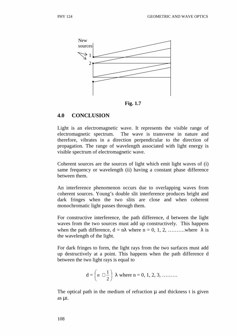
PHY 124 GEOMETRIC AND WAVE OPTICS
108
Fig. 1.7 4.0 CONCLUSION Light is an electromagnetic wave. It represents the visible range of electromagnetic spectrum. The wave is transverse in nature and therefore, vibrates in a direction perpendicular to the direction of propagation. The range of wavelength associated with light energy is visible spectrum of electromagnetic wave. Coherent sources are the sources of light which emit light waves of (i) same frequency or wavelength (ii) having a constant phase difference between them. An interference phenomenon occurs due to overlapping waves from coherent sources. Young’s double slit interference produces bright and dark fringes when the two slits are close and when coherent monochromatic light passes through them. For constructive interference, the path difference, d between the light waves from the two sources must add up constructively. This happens when the path difference, d = nλ where n = 0, 1, 2, ……….where λ is the wavelength of the light. For dark fringes to form, the light rays from the two surfaces must add up destructively at a point. This happens when the path difference d between the two light rays is equal to
d =
+2
1n λ where n = 0, 1, 2, 3, ………
The optical path in the medium of refraction µ and thickness t is given as µt.
1
2
New sources

PHY 124 GEOMETRIC AND WAVE OPTICS
109
The separation between any two adjacent bright or dark fringes Y depends on the distance a between the slits A and B. The mathematical expression is given by the relation
Y = a
Dλ
5.0 SUMMARY • Light lies in visible range of the electromagnetic spectrum.
Therefore light is an electromagnetic wave. • Light from two coherent sources can interfere either
constructively or destructively. • Young’s double slit experiment demonstrates the constructive
and destructive interference when light from coherent sources is obtained.
• The bright fringe represent constructive interference which takes place only when the path difference between light ray from the two sources is equal to nλ where n = 0, 1, 2, ……so on.
• The dark fringe represent destructive interference which takes place when the path difference d is equal to
d =
+2
1n λ where n = 0, 1, 2, ……so on.
• The separation between any two adjacent dark or bright fringes is
given by the relation Y = a
Dλ
6.0 TUTOR-MARKED ASSIGNMENT 1. Interference fringes were produced by a Young’s slit method, the
wavelength of the light being 6 x 10⁻⁷m when a film of material 3.6 x 10⁻³ cm thick was placed over one of the slit, the fringe pattern was displaced by the distance equal to 30 times that between two adjacent fringes. Calculate the refractive index of the material. To which side is the fringes displaced.
2. In a two-slit interference pattern with λ = 5600 Ao, the zero order
and tenth order maxima fall at 12.42mm and 14.64 mm respectively. Determine the fringe width.
3. In a Young’s slits experiment, the separation between the first and the sixth bright fringe is 3.0 mm when the wavelength used is 6.2 x 10⁻⁷m. The distance between the slits and the screen is 0.9m. Determine the separation of the two slits.
PHY 124 GEOMETRIC AND WAVE OPTICS
110
7.0 REFERENCES/FURTHER READINGS Nelkon and Parker. Advance Level Physics. British Library Publication. Kenneth .W. Ford. Basic Physics. Toronto London: Waltham
Massachusetts. Mark .W. Zemansky. College Physics. London: Addison – Wesley. Shortley and Williams. Principles of College Physics. Englewood Cliff
New Jersey: Prentice Hall Inc.

PHY 124 GEOMETRIC AND WAVE OPTICS
111
UNIT 2 INTERFERENCE IN THIN FILMS AND AIR WEDGE
CONTENTS 1.0 Introduction 2.0 Objectives 3.0 Main Content
3.1 Interference in thin Wedge Films 3.2 Phase Change in Reflection 3.3 The Air Wedge
4.0 Conclusion 5.0 Summary 6.0 Tutor-Marked Assignment 7.0 References/Further Readings 1.0 INTRODUCTION In the last unit, you studied the phenomenon of interference of light waves but there the two interfering light waves are produced by division of wave-front. As an example, in Young’s double slit experiment, how inference pattern is produced from two coherent light sources produced by the division of wave-front by the two slits A and B. but now you may ask: Is there any other method to produce interference pattern? You may have observed another set of interference pattern in thin films and Air wedge. In these patterns, two light beams derived from a single incident beam by division of amplitude of the incident wave. These interference patterns are produced due to optical path differences in thin films and Air wedge. The amplitude of the wave (measure of energy) is divided into parts. In this unit, you will study about interference patterns produced in thin film and Air wedge. You would also see that light reflected by a material of higher refractive index than the medium in which the rays are traveling undergoes 180o phase change. 2.0 OBJECTIVES After studying this unit, you will be able to: • explain what a thin film is • describe the origin of the interference pattern produced by a thin
film • show that reflection of light at the surface of optically denser
medium is accompanied by a phase change of 180o

PHY 124 GEOMETRIC AND WAVE OPTICS
112
• explain what an air wedge is • explain how the air wedge forms interference patterns • solve problems associated with interference in the thin films and
the air wedge. 3.0 MAIN CONTENT 3.1 Interference in Thin Wedge Films Here, we will consider the interference pattern produced by a film of varying thickness i.e. a film which is not plane parallel which is produced by a wedge. Refer to Fig. 2.1. It consist of two non-parallel surfaces inclined at an angle θ. Suppose a ray of light from a monochromatic source S strikes a half silvered mirror and reflected onto an air wedge.
Microscope or Eye S Half -silvered Mirror Air Wedge Microscopic Foil or Paper
Slope P Q
Fig. 2.1 (a): Air wedge Fig. 2.2 Magnified region
of reflection Light from a monochromatic source is partly reflected from the mirror onto an air wedge. The air wedge is formed by inclining two microscope slides at very small angle θ as shown in Fig. 2.1 above. If the region of reflection at the slides is magnified, the result is shown in Fig. 2.2. It can be seen from the Fig. 2.2 that some of the light is reflected from the lower surface of the top slide and some from the top side of the lower slide. Both wave trains R1 and R2 then combine together and gives rise to interference patterns when viewed from above the half silvered mirror by an eye or microscope.
Monochromatic source
R2 R1
θ

PHY 124 GEOMETRIC AND WAVE OPTICS
113
The two coherent sources are produce by division of amplitude. This is different from the Young’s experiment in which the sources are produced by division of wave-front. 3.2 Phase Change in Reflection There is a very significant fact concerning the reflection of waves from the surface of higher refractive index µ. The phase change of π (or 180o) occurs when the light strikes the boundary from the side of rarer medium. Hence, one can say that the light reflected by a material of higher refractive index than the medium in which the rays are traveling undergoes a phase change of π (or 180o). This phase change is
equivalent to a path change of2
λ. For example, consider two standing
waves as shown in Fig. 2 3 below: Fig. 2.3: Two standing waves having a phase difference of ππππ It can be seen that the phase difference and path difference between the
waves A and B are respectively π (180o) and 2
λ.
3.3 The Air Wedge Refer to Fig.2.4. Here θ is the angle of the wedge. S is the distance between bright bands. B and B′ are two consecutive bright bands. As θ is small, in triangle ∆ ACA′,
∴ tan θ = s
2λ
Or θ = s2
λ …….( 2.1)
Also, the vale of tan θ can be found as
B
A

PHY 124 GEOMETRIC AND WAVE OPTICS
114
tan θ = a
t
As the value of θ is very small. Therefore
or θ = a
t ……… (2.2)
On compairing Eq. (2.1) and Eq. (2.2), we get
θλ ==∴a
t
s2 ……….(2.3)
Here θ is measured in radians. A
Fig. 2.4 Suppose that the mth bright fringe is seen above A, one would expect that 2AB = mλ
However there is a path change of 2
λwhen light is reflected from B, thus
2AB + 2
λ = mλ
In general, the band is bright if
2AB = λ
−2
1m ………. (2.4)
And for dark band, the condition is 2AB = mλ Where m = 0, 1, 2 ……… (2.5) If at A′, the (m + 1)th bright fringe is seen then it follows that the extra path difference is 2 A′ B′ - 2AB = λ
a
C
A '
B' s θ
t θ
B
2
λ

PHY 124 GEOMETRIC AND WAVE OPTICS
115
A′ B′ - AB = λ/2
You may now like to attempt the following example to know whether you have grasped the concept of air wedge. Try the following example. Example 2.1 A wedge-shaped film of air between two glass plates gives equal spaced dark fringes, using reflected sodium light, which are 0.22 mm apart. When monochromatic light of another wavelength is used the fringes are 0.24 mm apart. Calculate the wavelength of the second source of light. Assume for sodium light λ = 589 nm.
Solution: As we know that θ = 1
1
22 sS
λλ = for the 1st source
Similarly, θ = 2
2
2s
λ
On comparing the above two equations
2
2
1
1
22 ss
λλ=∴
Or 1
212 2
2
s
sxλλ =
On substituting the values λ1 = 589 x 10-9 m, S2 = 0.024m, and S1 = 0.022 m We get λ2 = 589 x 10-9 x 0.024 0.022 λ2 = 643 nm 4.0 CONCLUSION Apart from the case of Young’s experiment in which interference occurs for coherent light originating from two different sources, interference can occur in thin films. In thin films, the interference results from the splitting of amplitude rather than the splitting of wave-front as in the Young’s experiment.

PHY 124 GEOMETRIC AND WAVE OPTICS
116
When light is reflected on a surface, the reflection is accompanied by a
phase change of 180o or π which is equivalent to path difference or 2
λ
(i.e. half a wavelength). Interference can also occur in the air wedge. Reflection also has a role to play in the formation of the interference pattern. Therefore, the
associated path difference between the reflection and the direct ray is 2
λ.
Generally, the bright fringe is governed by the relation 2AB =
−2
1m λ
whereas the formation of the dark fringes is given by the relation 2AB = mλ. 5.0 SUMMARY • The thin film can also produce interference fringes just as for two
coherent sources in the Young’s experiment. • While fringes are produced in the Young’s experiment due to
splitting of wave-front but interference pattern are produced in thin films due to splitting of amplitude.
• Reflection of light is associated with a phase of change of 180o or
π and a path difference of 2
λ.
• Interference can also be formed by thin films. In this case, the path difference for a bright fringe is governed by the relationship
2AB =
−2
1m λ while that of the dark fringe is governed by the
relationship 2AB = mλ. 6.0 TUTOR-MARKED ASSIGNMENT 1. Using monochromatic light of wavelength 5873Ao, an air wedge
is illuminated and the separation of the bright band is 0.29 mm. Calculate the angle of wedge.
2. An air wedge is illuminated perpendicularly by monochromatic
light of wavelength 5.73 x 10⁻⁷ m, interference fringes are produced parallel to the line of contact, which have separation of 1.25 mm. This air wedge film is formed by keeping a foil between two glass slides at a distance of 80 mm from the line of contact of the slides. Determine the angle of the wedge and the thickness of the foil.

PHY 124 GEOMETRIC AND WAVE OPTICS
117
7.0 REFERENCES/FURTHER READINGS Nelkon and Parker. Advance Level Physics. British Library Publication. Kenneth .W. Ford. Basic Physics. Toronto London: Waltham
Massachusetts. Mark .W. Zemansky. College Physics. London: Addison – Wesley. Shortley and Williams. Principles of College Physics. Englewood Cliff
New Jersey: Prentice Hall Inc.

PHY 124 GEOMETRIC AND WAVE OPTICS
118
UNIT 3 NEWTON’S RING AND INTERFERENCE IN THIN FILMS
CONTENTS 1.0 Introduction 2.0 Objectives 3.0 Main Content
3.1 Newton’s Rings 3.1.1 Radius of a Ring
3.2 Interference in Thin Films 4.0 Conclusion 5.0 Summary 6.0 Tutor-Marked Assignment 7.0 References/Further Readings 1.0 INTRODUCTION
In unit 2, you noted that apart from Young’s experiment, there are other ways of producing interference pattern by division of amplitude i.e. interference in air wedge. In this method, two light beams derived from the single incident beam by division of amplitude of the incident wave. It means, the amplitude of wave is divided into two parts. The other ways of producing interference are Newton’s ring and thin films. Newton rings were discovered by Newton. A lens is placed on a glass plate and an air film is formed between the lower surface of the lens and upper surface of the plane glass plate. As a result, a pattern of bright and dark fringes consist of concentric circles are formed.
Now in this unit, you will study about Newton’s rings and interference in thin films. 2.0 OBJECTIVES
After studying this unit, you will be able to:
• identify Newton’s ring • explain the theory of Newton’s ring • solve problems involving Newton’s ring • differentiate between Newton’s rings and interference by thin
film • explain a theory of interference in thin film • solve problems involving thin film.
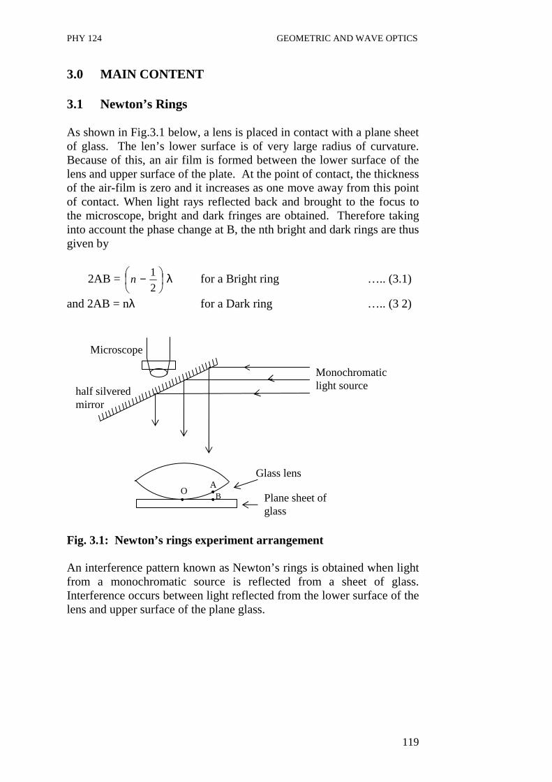
PHY 124 GEOMETRIC AND WAVE OPTICS
119
3.0 MAIN CONTENT 3.1 Newton’s Rings As shown in Fig.3.1 below, a lens is placed in contact with a plane sheet of glass. The len’s lower surface is of very large radius of curvature. Because of this, an air film is formed between the lower surface of the lens and upper surface of the plate. At the point of contact, the thickness of the air-film is zero and it increases as one move away from this point of contact. When light rays reflected back and brought to the focus to the microscope, bright and dark fringes are obtained. Therefore taking into account the phase change at B, the nth bright and dark rings are thus given by
2AB =
−2
1n λ for a Bright ring ….. (3.1)
and 2AB = nλ for a Dark ring ….. (3 2) Fig. 3.1: Newton’s rings experiment arrangement An interference pattern known as Newton’s rings is obtained when light from a monochromatic source is reflected from a sheet of glass. Interference occurs between light reflected from the lower surface of the lens and upper surface of the plane glass.
half silvered mirror
Microscope
Monochromatic light source
O A
B
Glass lens
Plane sheet of glass
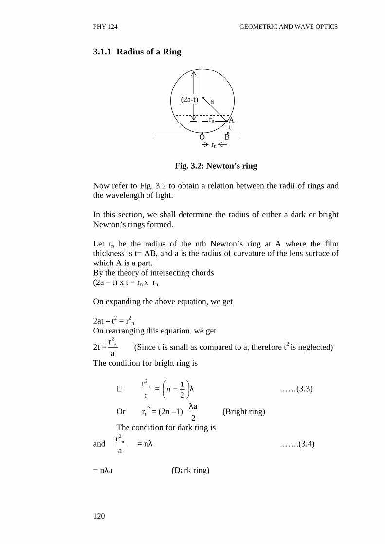
PHY 124 GEOMETRIC AND WAVE OPTICS
120
3.1.1 Radius of a Ring
Fig. 3.2: Newton’s ring Now refer to Fig. 3.2 to obtain a relation between the radii of rings and the wavelength of light. In this section, we shall determine the radius of either a dark or bright Newton’s rings formed. Let rn be the radius of the nth Newton’s ring at A where the film thickness is t= AB, and a is the radius of curvature of the lens surface of which A is a part. By the theory of intersecting chords (2a – t) x t = rn x rn On expanding the above equation, we get 2at – t2 = r2n
On rearranging this equation, we get
2t =2
nr
a (Since t is small as compared to a, therefore t2 is neglected)
The condition for bright ring is
∴ 2
nr
a =
−2
1n λ ……(3.3)
Or rn2 = (2n –1)
a
2
λ (Bright ring)
The condition for dark ring is
and 2
nr
a = nλ …….(3.4)
= nλa (Dark ring)
(2a-t)
rn
rn t A
B O
a
PHY 124 GEOMETRIC AND WAVE OPTICS
121
These expressions can also be easily written in terms of diameter of the ring. Suppose Dn is the diameter of the nth ring, then Eq.(3.3) and Eq. (3.4) becomes
Dn = 2rn ⇒ rn = nD
2
∴ Dn2= 2(2n-1) λa (Bright ring)
∴ Dn
2= 4 n λa (Dark ring)
Example 3.1
In a Newton’s rings experiment the radius of curvature of the lens is 5.0 m and its diameter is 2.0 cm. Determine (a) how many dark rings are produced? (b) how many dark rings would be seen if the arrangement were immersed in water of refractive index 1.33. Assume the wavelength of light used is 589 nm.
Solution
(a) Diameter of lens = Diameter of largest ring = 2.0 cm
∴ Radius of last ring r = 1.0 x 10⁻²m Radius of curvature a = 5.0 m Wavelength of light λ = 589 x 10-9m Using the equation and substituting the values n = r2 = (1.0 x 10⁻²)2 aλ 5.0 x 589 x 10-9
No. of rings (n) = 34 (b) If immersed in water the refractive index is
µw = w
air
w
air
f
f
λλ
λλ −=
When λair = vacuum wavelength of the light λw = wavelength of light in water µw = refractive index of water = 1.33
∴λw = w
air
µλ
and n =wa
r
λ
2
in water
n = 9
222
105890.5
33.1)100.1(−
−
=xx
xx
a
r
air
w
λµ
n= 46

PHY 124 GEOMETRIC AND WAVE OPTICS
122
Example 3.2 The diameter of the 7th and 17th bright rings formed by a plano- convex lens resting on a plane glass surface is respectively 0.14 cm and 0.86 cm. When the space between the lens and glass is filled with water, the diameter of the 11th and 21st bright rings is respectively 0.23 cm and 0.77 cm. What is the refractive index of water?
Solution
In air have
r12 = am 1 λa ……(3.5)
r22 = am 2 λa …..(3.6)
λa = wavelength in air m1 = 7 m2 = 17 Subtracting Eq.(3.5) from Eq.(3.6), we have r2
2 – r12 = (m 2 - m 1) a λa …..(3.7)
In water, we have r3
2 = am 3 λw …..(3.8) r4
2 = am 4 λw …..(3.9) λw = wavelength in water Subtracting Eq.(3.8) from Eq.(3.9), we have r4
2 – r32 = (m 4 - m 3) a λw …..(3.10)
Equation (3.7) divided by (3.10), gives r2
2 – r12 = (m 2 - m 1) a λa
r42 – r3
2 (m 4 - m 3) a λa µw
= 10
10 wµ
r2
2 – r12 = µw
r42 – r3
2
or µw = (0.862 – (0.142) (0.772) – (0.232) µw = 1.33 In the next section, you will study interference in the thin films.

PHY 124 GEOMETRIC AND WAVE OPTICS
123
3.2 Interference in thin Films A thin film is a very thin layer of the medium concerned. Examples of thin film are a soap film or a bubble and thin layer of oil spread over water surface. Such layers are also known to cause interference patterns. The details of how this is done are discussed below. Consider a thin transparent film of refractive index µ. A ray IA from a point monochromatic source is partly reflected as a ray AR and part refracted into the material of the film along AB, such that the r is the angle of refraction. At point B, the ray of light is partly reflected to A′, and partly transmitted out. At A′, the ray will again get partly reflected along A′B′ and refracted as ray A′R′. When these two rays, AR and A′R′, meet, then interference occurs as shown in Fig. 3.3. It is to be noted that the amplitude decreases from one ray to the next.
Fig. 3.3: Interference in thin film Let A′D is the perpendicular to AR. Then optical path difference between these rays is = µ (AB + BA′) – AD …... (3.5) But cos r = BT = t ⇒ t = BA′ = AB AB AB cosr .… (3.6) and sin i = AD AA′ ∴ AD = AA′ sin i AA′ = AT + TA′
Monochromatic source
Eye
R'
air
R
D
A ' i i
A
rC t
µ
I
B B'
air
r

PHY 124 GEOMETRIC AND WAVE OPTICS
124
AA′ = BT tanr + BT tanr = 2t tanr Therefore AD = 2t tanr sin i AD = 2t sin r sin i ….. (3.7) cosr Using Snell’s law as
µ = sin i ⇒ sin i = µ sinr .… (3.8) sinr Substitute Eq. (3.8) into Eq (3.7), we get AD = 2t sin r µ sinr cosr AD = 2µt. sin2 r
cosr Now substitute the value in Eq. (3.5), for the path difference, the expression is
Path diffrence = µ (t + t ) - 2µt sin2 r cos r cos r cos r
= 2µt (1 – sin2r) cosr = 2µt cos r [as sin2r + cos2r = 1]
At point A, the ray is reflected when it is going from a rarer to a denser medium and suffers a path difference of λ/2 or a phase change of π . But at B, the reflection takes place when the ray is going from a denser to a rarer medium, and hence there is no phase change. Hence the effective path difference between two rays is 2µt cos r - λ 2 The condition for destructive interference in the film is given by 2µt cos r - λ = (2n-1) λ 2 2 2µt cos r= n λ where n = 1, 2, ………….. The condition for constructive interference is

PHY 124 GEOMETRIC AND WAVE OPTICS
125
2µt cos r - λ = n λ 2 2µt cos r = (2n +1) λ 2
Where n = 0,1,2 ……….. Example 3.3 White light falls on a soap film with a refractive index of 1.33 at an angle of 45o. What must be the minimum thickness of the film for the reflected rays to be yellow and a wavelength of 6.0 x 10⁻⁷m. Solution For a bright fringe, we have the condition
2µt cosr = (2n+1) 2
λ
where µ is the refractive index of thin film = 1.33
t = thickness of film λ = wavelength of light = 6 x 10⁻⁷m
t = r
n
cos2
)21(
µ−
λ ….(3.8)
From Eq. 3.8, the minimum value of t occurs when r = 1 ∴ tmin = (1 – ½ ) x 6.0 x 10⁻⁷ 2 x 1.33 x cos r Using Snell’s law at point A, we have
µ = sin i = sin 45 sin r sin r
t
45o
r

PHY 124 GEOMETRIC AND WAVE OPTICS
126
1.33 = sin 45 sin r
r = 32.1
∴ tmin = 6.0 x 10⁻⁷ / 2 x 1.33 x cos (32.1) = 1.3 x 10 -7 m 4.0 CONCLUSION • Newton’s ring is a spherical form of interference in an air wedge,
it result from path difference between light reflected from the bottom of the lens and the top of transparent mirror.
• The air wedge is formed between a lens and a flat mirror over which the lens is placed
• The equation governing the formation of bright and dark fringes in Newton’s ring are
2AB = λ
−2
1n for Bright fringes
and 2AB = nλ for Dark fringes.
• Relationship between the radius of a fringe and the radius of the curvature of the lens is given by
2
nr
a =
−2
1n λ for a Bright ring
2
nr
a = nλ for a Dark ring
• Interference also occurs in thin film and this is due to the path difference between monochromatic light reflected on the top and bottom of thin films. A bright fringe in this case occurs when a
path difference, d = 2µ t cos r = (2n+1) 2
λ where n =
0,1,2……….
On the other hand a dark fringe occurs when the path difference, d = 2µ t cos r = nλ where n = 1,2,……..
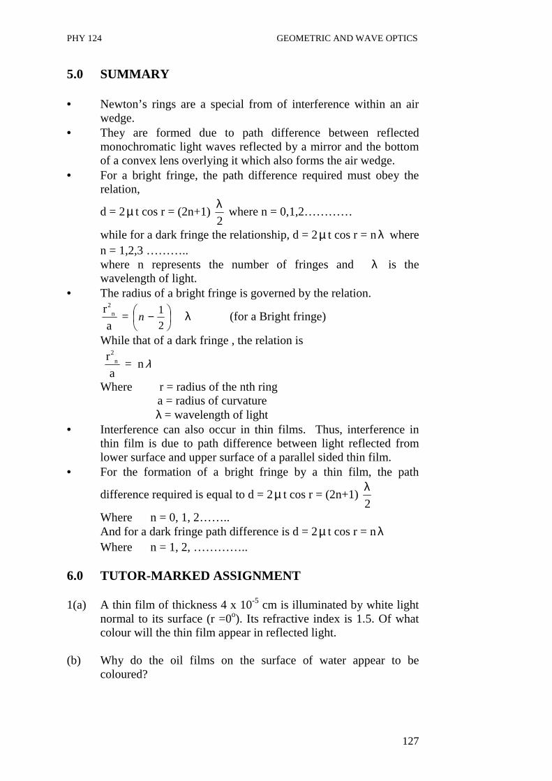
PHY 124 GEOMETRIC AND WAVE OPTICS
127
5.0 SUMMARY • Newton’s rings are a special from of interference within an air
wedge. • They are formed due to path difference between reflected
monochromatic light waves reflected by a mirror and the bottom of a convex lens overlying it which also forms the air wedge.
• For a bright fringe, the path difference required must obey the relation,
d = 2µ t cos r = (2n+1) 2
λ where n = 0,1,2…………
while for a dark fringe the relationship, d = 2µ t cos r = nλ where n = 1,2,3 ……….. where n represents the number of fringes and λ is the wavelength of light.
• The radius of a bright fringe is governed by the relation. 2
nr
a =
−2
1n λ (for a Bright fringe)
While that of a dark fringe , the relation is
2
nr
a = nλ
Where r = radius of the nth ring a = radius of curvature
λ = wavelength of light • Interference can also occur in thin films. Thus, interference in
thin film is due to path difference between light reflected from lower surface and upper surface of a parallel sided thin film.
• For the formation of a bright fringe by a thin film, the path
difference required is equal to d = 2µ t cos r = (2n+1) 2
λ
Where n = 0, 1, 2…….. And for a dark fringe path difference is d = 2µ t cos r = nλ Where n = 1, 2, …………..
6.0 TUTOR-MARKED ASSIGNMENT 1(a) A thin film of thickness 4 x 10⁻⁵ cm is illuminated by white light
normal to its surface (r =0o). Its refractive index is 1.5. Of what colour will the thin film appear in reflected light.
(b) Why do the oil films on the surface of water appear to be
coloured?

PHY 124 GEOMETRIC AND WAVE OPTICS
128
7.0 REFERENCES/FURTHER READINGS Nelkon and Parker. Advance Level Physics. British Library Publication. Kenneth .W. Ford. Basic Physics. Toronto London: Waltham
Massachusetts. Mark .W. Zemansky. College Physics. London: Addison – Wesley. Shortley and Williams. Principles of College Physics. Englewood Cliff
New Jersey: Prentice Hall Inc.

PHY 124 GEOMETRIC AND WAVE OPTICS
129
UNIT 4 POLARIZATION OF LIGHT CONTENTS 1.0 Introduction 2.0 Objectives 3.0 Main Content 3.1 Polarized and un-polarized light 3.2 Optical Activity 3.3 Methods of Polarization 3.3.1 By Reflection 3.3.2 By Refraction 3.3.3 By Double Refraction 4.0 Conclusion 5.0 Summary 6.0 Tutor-Marked Assignment 7.0 References/Further Readings 1.0 INTRODUCTION In our earlier units, you have thus far studied about interference which illustrates the wave nature of light. You have seen that these waves are transverse waves. Another phenomenon known as polarization also shows the transverse nature of light. When a light is obtained from a source, this ordinary light vibrates in virtually all directions perpendicular to the direction of propagation. Hence, it is called unpolarized light. But light can be constrained by either natural or artificial crystals to vibrate in only one plane perpendicular to the direction of propagation. When this happens, the light is referred to as polarized light. In this unit, you will study the various ways of producing polarized light and you will also come across with various crystals that can be used to produce polarized light. 2.0 OBJECTIVES After studying this unit, you should be able to:
• differentiate polarized and unpolarised light • describe the various ways of producing polarized light • identify the crystals that can produce polarized light • explain the theory behind each method of producing polarized
light • define and explain optical activity • solve problems associated with production of polarized light.
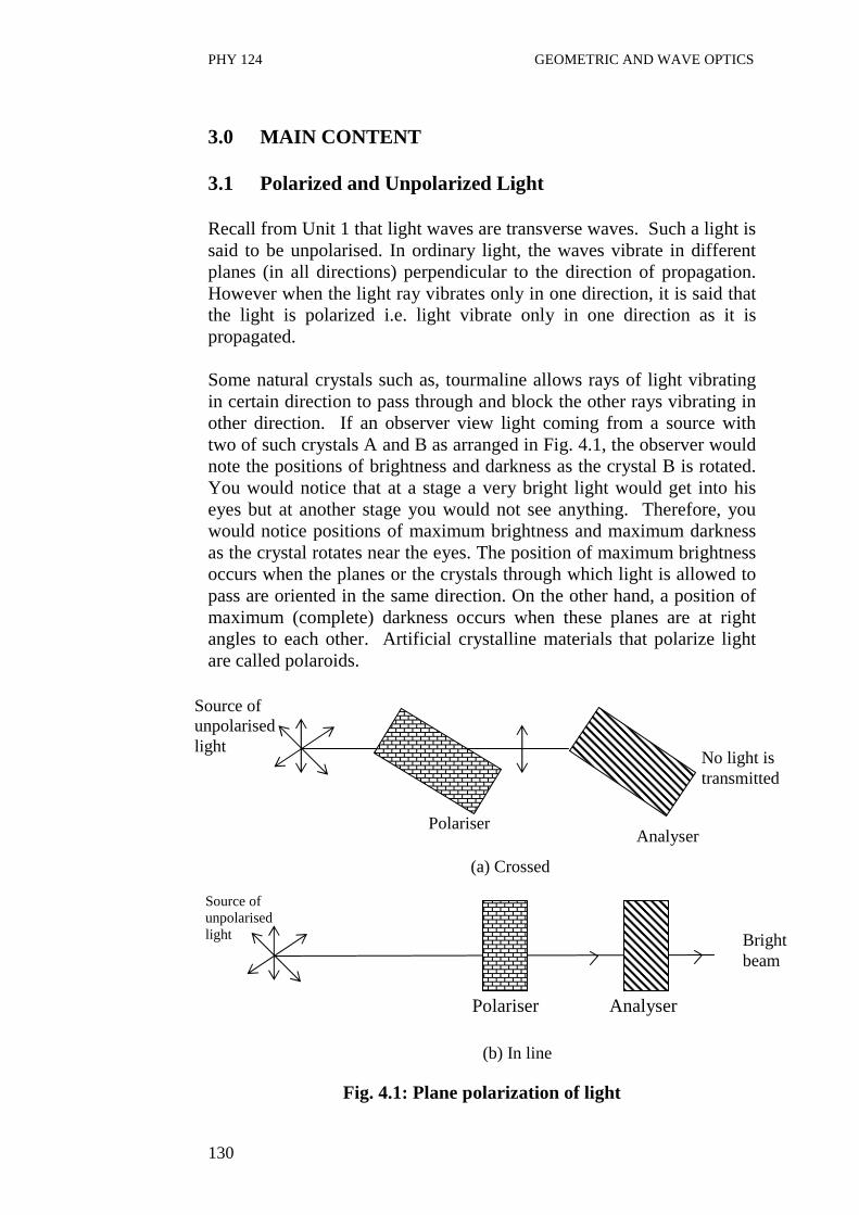
PHY 124 GEOMETRIC AND WAVE OPTICS
130
3.0 MAIN CONTENT 3.1 Polarized and Unpolarized Light Recall from Unit 1 that light waves are transverse waves. Such a light is said to be unpolarised. In ordinary light, the waves vibrate in different planes (in all directions) perpendicular to the direction of propagation. However when the light ray vibrates only in one direction, it is said that the light is polarized i.e. light vibrate only in one direction as it is propagated. Some natural crystals such as, tourmaline allows rays of light vibrating in certain direction to pass through and block the other rays vibrating in other direction. If an observer view light coming from a source with two of such crystals A and B as arranged in Fig. 4.1, the observer would note the positions of brightness and darkness as the crystal B is rotated. You would notice that at a stage a very bright light would get into his eyes but at another stage you would not see anything. Therefore, you would notice positions of maximum brightness and maximum darkness as the crystal rotates near the eyes. The position of maximum brightness occurs when the planes or the crystals through which light is allowed to pass are oriented in the same direction. On the other hand, a position of maximum (complete) darkness occurs when these planes are at right angles to each other. Artificial crystalline materials that polarize light are called polaroids. Polariser Analyser
Fig. 4.1: Plane polarization of light
Source of unpolarised light
Polariser Analyser
No light is transmitted
(a) Crossed
Bright beam
(b) In line
Source of unpolarised light
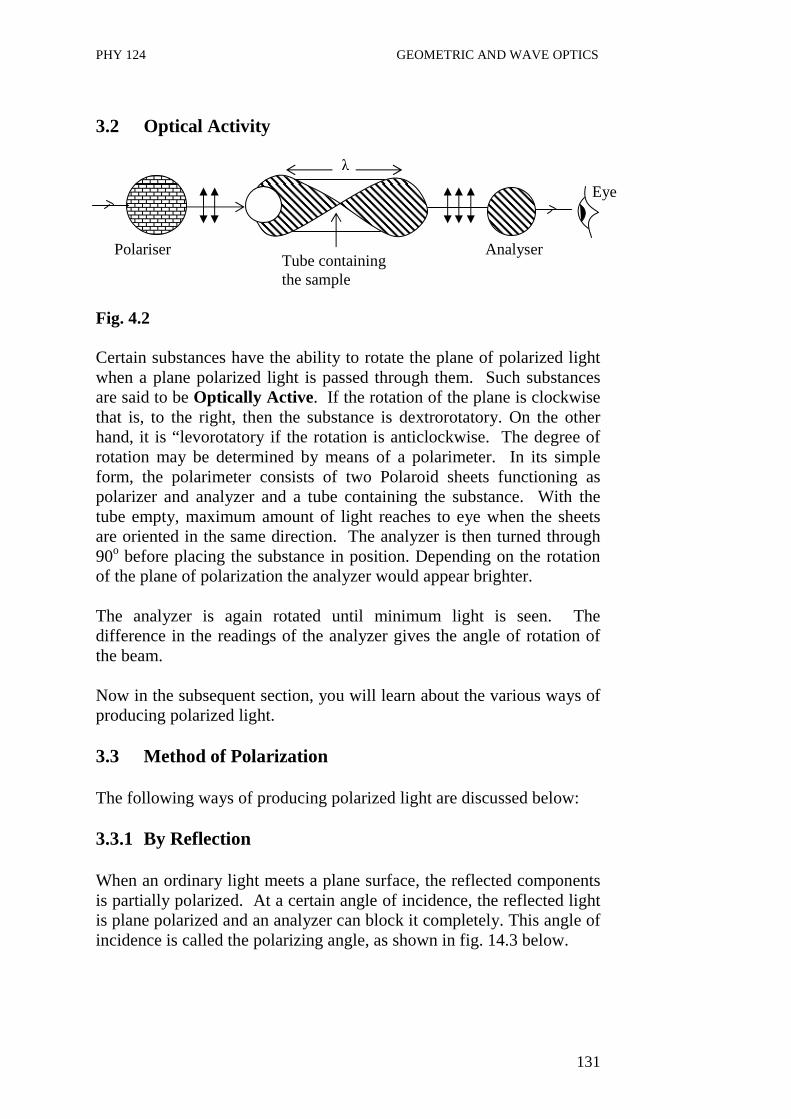
PHY 124 GEOMETRIC AND WAVE OPTICS
131
3.2 Optical Activity Fig. 4.2 Certain substances have the ability to rotate the plane of polarized light when a plane polarized light is passed through them. Such substances are said to be Optically Active. If the rotation of the plane is clockwise that is, to the right, then the substance is dextrorotatory. On the other hand, it is “levorotatory if the rotation is anticlockwise. The degree of rotation may be determined by means of a polarimeter. In its simple form, the polarimeter consists of two Polaroid sheets functioning as polarizer and analyzer and a tube containing the substance. With the tube empty, maximum amount of light reaches to eye when the sheets are oriented in the same direction. The analyzer is then turned through 90o before placing the substance in position. Depending on the rotation of the plane of polarization the analyzer would appear brighter. The analyzer is again rotated until minimum light is seen. The difference in the readings of the analyzer gives the angle of rotation of the beam. Now in the subsequent section, you will learn about the various ways of producing polarized light. 3.3 Method of Polarization The following ways of producing polarized light are discussed below: 3.3.1 By Reflection When an ordinary light meets a plane surface, the reflected components is partially polarized. At a certain angle of incidence, the reflected light is plane polarized and an analyzer can block it completely. This angle of incidence is called the polarizing angle, as shown in fig. 14.3 below.
Tube containing the sample
Polariser Analyser
Eye
λ
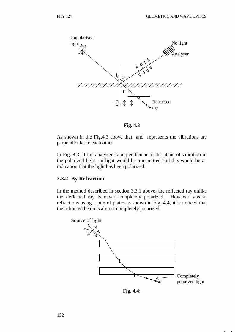
PHY 124 GEOMETRIC AND WAVE OPTICS
132
Fig. 4.3 As shown in the Fig.4.3 above that and represents the vibrations are perpendicular to each other. In Fig. 4.3, if the analyzer is perpendicular to the plane of vibration of the polarized light, no light would be transmitted and this would be an indication that the light has been polarized. 3.3.2 By Refraction In the method described in section 3.3.1 above, the reflected ray unlike the deflected ray is never completely polarized. However several refractions using a pile of plates as shown in Fig. 4.4, it is noticed that the refracted beam is almost completely polarized.
Source of light
Fig. 4.4:
ip ip
Refracted ray
r
No light Analyser
Unpolarised light
Completely polarized light

PHY 124 GEOMETRIC AND WAVE OPTICS
133
Apart from the two methods studied to obtain polarization, we will now learn about polarization by double refraction in the next section. 3.3.3 By Double Refraction There exist many transparent crystalline substances which while homogenous, are anisotropic. That is the velocity of a light wave in them is not the same in all directions. Crystals having this property are said to be doubly refracting. In such a crystal, two sets of Huygens wavelets propagate, one set being spherical and the other ellipsoidal. The two sets are perpendicular to one another and also perpendicular to an axis of the crystal at which the velocity of all wave is the same.
Fig. 4.5: It is to be noted that any line parallel to the optic axis is also an optic axis when light is passed perpendicular to the surface of the crystal; the incident ray is broken up into two rays in traversing the crystal. The ray which corresponds to the spherical wavelength remains undeviated and is called an ordinary ray . The ray corresponding to the ellipsoidal wavelet is deviated and is called the extra-ordinary ray. Source of light
Fig. 4.6: Both the ordinary and extra ordinary ray comes out polarize. If the crystal is rotated about the incident ray as an axis, the ordinary ray
Spherical wavelet
Ellipsoidal wavelet
Optic axis Crystal
Extraordinary ray
Crystal
Ordinary ray
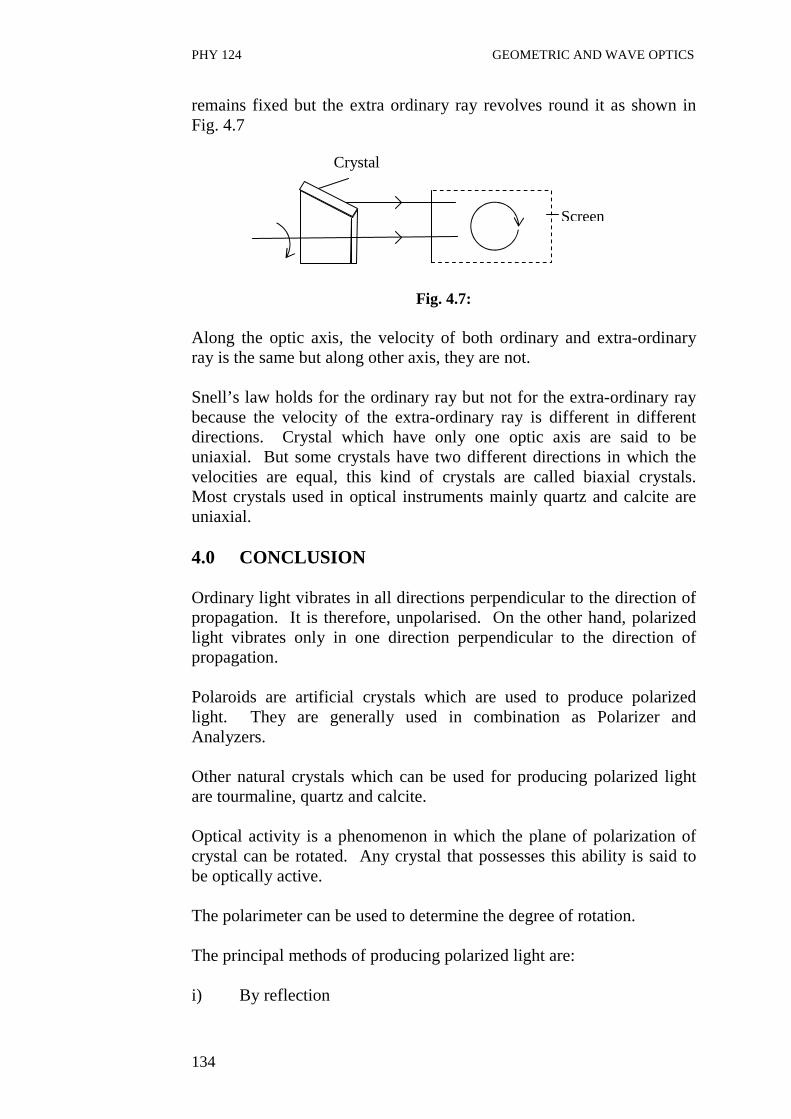
PHY 124 GEOMETRIC AND WAVE OPTICS
134
remains fixed but the extra ordinary ray revolves round it as shown in Fig. 4.7
Fig. 4.7:
Along the optic axis, the velocity of both ordinary and extra-ordinary ray is the same but along other axis, they are not. Snell’s law holds for the ordinary ray but not for the extra-ordinary ray because the velocity of the extra-ordinary ray is different in different directions. Crystal which have only one optic axis are said to be uniaxial. But some crystals have two different directions in which the velocities are equal, this kind of crystals are called biaxial crystals. Most crystals used in optical instruments mainly quartz and calcite are uniaxial. 4.0 CONCLUSION Ordinary light vibrates in all directions perpendicular to the direction of propagation. It is therefore, unpolarised. On the other hand, polarized light vibrates only in one direction perpendicular to the direction of propagation. Polaroids are artificial crystals which are used to produce polarized light. They are generally used in combination as Polarizer and Analyzers. Other natural crystals which can be used for producing polarized light are tourmaline, quartz and calcite. Optical activity is a phenomenon in which the plane of polarization of crystal can be rotated. Any crystal that possesses this ability is said to be optically active. The polarimeter can be used to determine the degree of rotation. The principal methods of producing polarized light are: i) By reflection
Screen
Crystal

PHY 124 GEOMETRIC AND WAVE OPTICS
135
ii) By refraction iii) By Double refraction 5.0 SUMMARY • While unpolarized light vibrate in all direction perpendicular to
the direction of propagation, polarized light vibrate in only one direction perpendicular to the direction of propagation.
• Polaroids, tourmaline, calcite and quartz can be used to produce polarized light.
• A pair of Polaroid can be used as polarizer and Analyzer to study the polarization of light.
• The ability to rotate the plane of polarization of a crystal is related to its optical activity.
• The magnitude of the optical activity of the crystalline can be determined by using the polarimeter.
• Other principal ways of producing polarised light include by reflection, by refraction and by double refraction.
6.0 TUTOR-MARKED ASSIGNMENT 1. What are the different methods by which polarized light can be
obtained? Explain. 2. State any two useful applications of plane polarized waves. 7.0 REFERENCES/FURTHER READINGS Nelkon and Parker. Advance Level Physics. British Library Publication. Kenneth .W. Ford. Basic Physics. Toronto London: Waltham
Massachusetts. Mark .W. Zemansky. College Physics. London: Addison – Wesley. Shortley and Williams. Principles of College Physics. Englewood Cliff
New Jersey: Prentice Hall Inc.
PHY 124 GEOMETRIC AND WAVE OPTICS
136
UNIT 5 LAWS AND APPLICATION O POLARIZATION CONTENTS 1.0 Introduction 2.0 Objectives 3.0 Main Content 3.1 Brewster’s Law 3.2 Percentage of Polarization 3.3 Malu’s Law 4.0 Conclusion 5.0 Summary 6.0 Tutor-Marked Assignment 7.0 References/Further Readings 1.0 INTRODUCTION In Unit 4, you learnt about the polarization of light. You studied that polarization of a light can be obtained by different ways like polarization by reflection, polarization by refraction and polarisation by double refraction. An ordinary light vibrates in every plane at right angles to the direction of light. Then the question arises: apart from the above mentioned methods, is there any laws which govern the polarization? Yes, there are certain laws which govern polarization. These include Brewster’s and Malu’s Law. In this unit, Brewster and Malus law would be derived and examined in detail. Also discuss the various applications of polarization in the end of this unit. 2.0 OBJECTIVES After studying this unit, you should be able to: • define and explain Brewster’s law • define and explain Malu’s law • solve problems involving Brewster’s and Malu’s law • list the applications of polarization of light.

PHY 124 GEOMETRIC AND WAVE OPTICS
137
3.0 MAIN CONTENT 3.1 Brewster’s Law µ
Fig. 5.1: Polarization by reflection Brewster’s observed that when unpolarised light is incident on a material, the reflected and refracted ray are at an angle of 90o as shown in Fig. .5.1. Using Snell’s law, we know that refractive index of a material is given by the relation
rsin
isin p=µ
Here ip is the polarizing angle. It is defined as the angle of incidence when the reflected light is almost completely polarized. µ is the refractive index of the material. But from the Fig. 5.1, one can see that r = 90 - ip
∴µ = ipcos
ipsin
)i90sin(
isin
p
p =−
= tan ip
∴Refractive index µ = tan ip ……. (5.1) Eq 5.1 is called Brewster’s law. Therefore, the refractive index of a transparent medium is equal to the tangent of the polarizing angle ip Thus Eq. 5.1, (Brewster law) can be used to find the refractive index of materials. For further clarity, you should now work out an example.
ip r 90o
Ordinary light

PHY 124 GEOMETRIC AND WAVE OPTICS
138
Example 5.1 (a) At what angle of incidence will light be reflected from water of
refractive index 1.33 and would it be completely polarized? (b) Does the angle depend on the wavelength of light? Solution
Let µ is = refractive index of water = 1.33 Using Brewster’s law given by Eq. 5.1, tan ip = µ
∴ tan ip = 1.33 ip = tan-1 (1.33) ip = 53o 1o
b) Yes, the angle depends on the wavelength of light because the refractive index of a medium with respect to the other varies with wavelength.
3.2 Percentage of Polarization
Fig. 5.2
when light passes through a Polaroid (or polarizer), the light which has vibration along the specified direction of the crystal above is transmitted (refer Fig. 5.2). If the transmitted light intensity is measured by means of a photocell, the current measured remains constant in whatever direction the polarizer is rotated. If there is any variation in the intensity, it shows that the incident light is partially polarized. That is, the vibration of the incident beams are not uniform in all directions.
The percentage of polarization (p) is given by P = I max – I min x 100 I max x I min .… (5.2)
When Imax = maximum light intensity
I min = minimum light intensity
Photocell
Polaroid sheet
Unpolarised light

PHY 124 GEOMETRIC AND WAVE OPTICS
139
3.3 Malu’s Law
Fig. 5.3 Fig. 5.4: Two components of polarized light. This section explains in detail the theory behind Malu’s law. Refer to Fig. 5.3 above. An analyzer is introduced between a polarizer and a photo cell. The specified direction of the polarizer makes an angle θ with the analyzer being oriented vertically. The polarized light transmitted by the polarizer can be resolved into two components, therefore, Eocos θ vertically and Eo sin θ horizontally, as shown in Fig. 5.4, where Eo is the amplitude vector of the incident beam. Only the component of amplitude Eo cos θ , which is parallel to the transmission direction, would be transmitted by the analyzer. The transmitted light is maximum when θ is 0o and is zero (minimum) when θ is 900. At intermediate angles, the intensity is proportional to the amplitude, and we have I0α Eo
2, and I α E2
∴ 2
222
0
cos
Eo
Eo
E
E
I
I
o
θ==
∴ I = Io cos2 θ …. (5.3)
Photocell
Polariser
Unpolarised light
θ
Eo
E
Analyser
Analyser
θ
Polariser
Eo cos θ
Eo sin θ

PHY 124 GEOMETRIC AND WAVE OPTICS
140
This equation (5.3) is known as Malu’s law Therefore from Eq. (5.3), it can be seen that he intensity of the emergent light varies as the square of the cosine of the angle between the polarizer and the analyzer. Example 3 A beam of plane polarized light strikes two polarizing sheets. The first sheet is inclined at a angle θ with respect to the incident beam, while the second sheet is inclined at 900 to the incident beam. Determine to the nearest degree, the angle θ for a transmitted beam intensity that is one tenth the incident beam intensity. Solution
Fig. 5.5
Apply Malu’s law to the first Polaroid we have I1 = Io cos2 θ ………………(1) and to the second Polaroid we have I2 = Io cos2 θ cos2 (90 -θ) I2 = Io cos2 θ sin2 θ
oI
I 2 = cos2 θ sin2 θ
but oI
I 2 = 10
1
∴ 10
1 = cos2 θ sin2 θ
Incident beam
Io
I1
I2
90 - θ
Incident beam
Second beam

PHY 124 GEOMETRIC AND WAVE OPTICS
141
10
1 = cos θ sin θ
= 2
1 sin 2θ
2
10
1 = sin 2 θ
θ = 200
3.4 Application of Polarization (a) Use of Polaroids in Sunglasses Unpolarised light is harmful to the human eye, but with the use of Polaroid this can be prevented. They protect our eyes from glare. They helped to reduce the intensity of sunlight. (b) In Film Industries Polarised light is used in films to create illusion of three dimensional pictures. (c) Saccharimetry The rotation of the plane of polarization by sugar solution is used as a method of determining the concentration of sugar solution in a given sample. (d) Photoelectric Stress Analysis Some substances such as glass and plastic, that are not normally double refracting, may become so if subjected to stress. If such stressed materials are placed between a polarise and analyzer, the bright and dark areas that are seen give information about the strains. The technology of photo-elasticity is based on double refraction produce by stresses. (e) Used in window pares The window panes of airplane and trains used polaroids to control the light entering through them.
PHY 124 GEOMETRIC AND WAVE OPTICS
142
4.0 CONCLUSION Brewster’s law is one of the laws applied in the study of polarization of light. Whenever unpolarized light is incident on a surface at the Brewster angle ip, the angle between the resulting reflected and refracted ray is found to be 90o. Under this condition, the refractive index of the medium concerned is given by µ = tan ip .This is a Brewster’s law. The pencentage of polarization of a given light cell can be found by applying Malus law to a polarized and analyzer used to view light. Malu’s law is given by the relationship I = Io cos2 θ Polarisation of light can be applied in the following areas: i) Used as sunglasses; ii) In the film industries for three dimensional pictures; iii) To determine the level of concentration of sugar solution
(saccharimetry); and iv) For photoelectric stress analysis. 5.0 SUMMARY • Two major laws used in polarization of light are Brewster’s law
and Malu’s law. • While Brewster’s law relates refractive index to the Brewster
angle, Malu’s law relates the percentage of polarization to the angle of rotation of the plane of polarization.
• That is, Brewster’s law is given by µ = tan ip while Malu’s law is
given by I = Io cos2 θ . • The industrial uses of polarization of light include: - The use of Polaroids as sunglasses; - The use of Polaroids in the film industries i.e. 3D effects; - The determination of concentration of sugar solution; - For photoelastic stress analysis; and - The one of polaroids in window panes. 6.0 TUTOR-MARKED ASSIGNMENT 1. A polarized and analyzer are oriented so that the maximum
amount of light is transmitted. To what fraction of maximum value is the intensity of the transmitted light reduced when the analyzer is rotated through 60o?

PHY 124 GEOMETRIC AND WAVE OPTICS
143
2. A beam of light falls on the surface of a glass plate of refractive index 1.536 at the polarizing angle. Determine the angle of refraction.
3. Let θ be the angle between the polarizer and the analyzer. Using
the Malu’s law, plot a graph showing the dependence of intensity of transmitted light on θ
7.0 REFERENCES/FURTHER READINGS Nelkon and Parker. Advance Level Physics. British Library Publication. Kenneth .W. Ford. Basic Physics. Toronto London: Waltham
Massachusetts. Mark .W. Zemansky. College Physics. London: Addison – Wesley. Shortley and Williams. Principles of College Physics. Englewood Cliff
New Jersey: Prentice Hall Inc.