Embed Size (px)
Citation preview

UCRL-ID-126998 Rev 2
National Ignition FacilitySystem Design Requirements
Laser SystemSDR002
D. W. Larson, J. M. Bowers,E. S. Bliss, V. P. Karpenko,
and E. English
August 20, 1996
Lawren
ce
Livermore
National
Labora
tory
This is an informal report describing scientific and technical research ranging from preliminary or exploratory investigations, informal proposals, and formulations of technical problems still in the speculative stage to the reporting of final research results. The opinions and conclusions stated are those of the author and may or may not be those of the Laboratory.
Work performed under the auspices of the Department of Energy by the Lawrence Livermore National Laboratory under Contract W-7405-Eng-48.

DISCLAIMER
This document was prepared as an account of work sponsored by an agency of the United States Government. Neitherthe United States Government nor the University of California nor any of their employees, makes any warranty, expressor implied, or assumes any legal liability or responsibility for the accuracy, completeness, or usefulness of anyinformation, apparatus, product, or process disclosed, or represents that its use would not infringe privately ownedrights. Reference herein to any specific commercial product, process, or service by trade name, trademark,manufacturer, or otherwise, does not necessarily constitute or imply its endorsement, recommendation, or favoring bythe United States Government or the University of California. The views and opinions of authors expressed herein donot necessarily state or reflect those of the United States Government or the University of California, and shall not beused for advertising or product endorsement purposes.
This report has been reproduceddirectly from the best available copy.
Available to DOE and DOE contractors from theOffice of Scientific and Technical Information
P.O. Box 62, Oak Ridge, TN 37831Prices available from (615) 576-8401, FTS 626-8401
Available to the public from theNational Technical Information Service
U.S. Department of Commerce5285 Port Royal Rd.,
Springfield, VA 22161

NIF-0000192-2WBS 1.3
National Ignition Facility
System Design Requirements
Laser System
SDRO02
Revision 2August 20,1996
Prepared by:D.W. Larson, Laser System Engineer @p& .
J.M. Bowers, Beam Transport System Engineer
E.S. Bliss, System Controls System Engineer
V.P. Karpenko, Target Experimental System Engineer
E. English Optical Integration Engineer Manager -u
~Jb h bhe%)
Engineering Review Board Approval:
S. Kumpan, NIP Project Engineer
Approval Date
Level 3 Change Control Board Approval:
J. Paisner, NIF Laboratory Project Manager
Approval Date *
.
NIF - SDRO02 - Laser System Design Requirements Revision 2
Table of Contents
Pmuwwb
;::2.12.1.12.1.22.1.32.1.42.22.2.12.2.22.32.4
;:; .13.1.23.1.33.1.3.13.1.43.1.53.1.5.013.1.5.023.1.5.033.1.5.043.1.5.053.1.5.063.1.5.073.1.5.083.1.5.093.1.5.103.1.5.113.1.5.123.1.5.133.23.2.13.2.1.013.2.1 .01.13.2.1 .01.23.2.1 .01.33.2.1.02
3.2.1.033.2.1.043.2.1.053.2.1.063,2.1.07
Xm
scopeApplicable DocumentsApplicable NIP DocumentsApplicable NIP Project DocumentsApplicable NTFDrawingsInterface Control DocumentsSubsystem Design Requirements DocumentsApplicable US Government Orders and StandardsDOE OrdersOther Government RegulationsApplicable National Consensus Codes and StandardsApplicable LLNL StandardsSystem DefinitionSystem DescriptionSystem FunctionsSystem DiagramsSystem Operating ModesPrimary InterfacesMajor SubsystemsOptical Pulse Generation System WBS 1.3.1Amplifier System WBS 1.3.2Pockels Cell System WBS 1.3.3Amplifier Power Conditioning System WBS 1.3.4Laser Auxiliary Systems WBS 1.3.5Beam Transport Enclosures WBS 1.4.1Interstage Subsystems WBS 1.4.2support structures WBs 1.4.3Beam Transport Optomechanical Systems WBS 1.4.4Alignment Systems WBS 1.7.1Beam Diagnostics WBS 1.7.2Wavefront Control System WBS 1.7.3Final Optics Assemblies WBS 1.8.7Requirements and VerificationPerformance CharacteristicsLaser Energy and PowerRoutine Operating Energy and PowerMaximum Design Energy and PowerOperating Energy and Power EnvelopeLaser Pulse Wavelength
10 WavelengthsPower BalanceBeam Positioning Accuracy and StabilityLaser Pulse DurationLaser Pulse Dynamic Range

.
.
NIF - SDRO02 - Laser System Design Requirements Revision 2
h-
3.2.1.083.2.1.093.2.1.103.2.1.113.2.1.123.2.1.133.2.1.143.2.1.153.2.1 .15.13.2.1 .15.23.2.1 .15.33.2.1 .15.43.2.1.16
3.2.1.173.2.1.183.2.1,193.2.1.203.2.1.213.2.1.223.2.1 .22.13.2.1 .22.23.2.1 .22.2.13,2.1 .22.2.23.2.1 .22.2.33.2.1.233.2.23.2.2.13.2.2.1.13.2.2.1.23.2.2.2.3.2.2.2.13.2.2.2.23.2.2.2.33.2.2.2.43.2.33.2.3.13.2.3.23.2.3.33.2.3.43.2.3.53.2.3.63.2.43.2.4.13.2.4.23.2.4.3
Table of Contents
Xi&
Capsule Irradiation SymmetryPre-pulse PowerLaser Pulse Spot SizeBeam SmoothnessAnnual Number of Shots with Fusion YieldShot Turn-Around TimeDiagnostic Instrument Capabilities to Verify Laser PerformanceLaser Firing FlexibilityBundle Firing FlexibilityBeam Firing FlexibilityBeam pulse Shape FlexibilityLaser Bay Operating FlexibilityBeam Focusing and Pointing Flexibility
Management of Unconverted ( la and 20) LightOptical Clear AperhueNumber of BeamsSRRS SuppressionLow-Power and Low-Energy Laser PulsesExperiment CompatibilityClassification Level of ExperimentsFuture Upgrades for Other UsersFuture Additional Target ChamberRadiation Effects Testing CapabilityOther User NeedsLaser System Grounding SystemPhysical CharacteristicsGeneral ArrangementLaser System ArchitectureGeneral Arrangement DrawingsLaser System General Cor@urationLaser BundlesLaser QuadsLaser ClustersLaser BaysReliability, Availability, MaintainabilityLifetimeReplaceabilityInherent AvailabilityReliabilityMaintainabilityRecovery from Abnormal EventsEnvironmentalOperating Ambient Temperature/HumidityAmbient CleanlinessAmbient Random Vibration Environment

NIF - SDRO02 - Laser System Design Requirements Revision 2
3.2.4.43.33.3.013.3.01.023.3.023.3.033.3.03.13.3.03.23.3.03.33.3.03.43.3.03.53.3.043.3.04.13.3.04.23.3.053.3.05.13.3.05.23.3.063.3.073.3.083.3.113.3.123.3.133.3.143.3.14.13.3.153.3.16
;::. 13.4.23.4.33.63.6.013.6.023.6.033.6.04
3.6.053.6.06
3.6.073.6.083.6.093.6.103.6.11
Table of Contents
Back-Reflected LightDesign and ConstructionHazard ClassificationNatural Hazards ClassificationRadiation ProtectionSafetyLife SafetyLaser SafetyOccupational SafetyFail-Safe DesignFire ProtectionCleanlinessInternal Optical CleanlinessGeneral CleanlinessEnvironmental Protection RequirementsWaste ManagementEffluentsSafeguards and SecurityFuture Modificationsand upgradesDecontamination and DecommissioningHuman FactorsInterchangeabilityDocumentation and RecordsElectrical PowerVoltage QualityDesign ProcessesSupervisory Software Access to Distributed Control PointsLogisticsSpare EquipmentMaintenance EquipmentBottom-Access MaintenanceMajor Subsystem Characteristics and VeriilcationOptical Pulse Generation characteristics and Verification (WIN 1.3.1)Amplifier Subsystem Characteristics and Verification (WBS 1.3.2)Pockels Cell System Characteristics and Verification (WBS 1.3.3)Amplifier Power Conditioning System Characteristics and Verification
(wBS 1.3.4)Laser Auxiliary Systems Characteristics and Verification (WBS 1.3.5)Beam Transport Enclosures Characteristics ~d Verification
(wBS 1.4.1)Interstage SubSystems Characteristics and Verification (WBS 1.4.2)Support Structures Characteristics and Verification (WBS 1.4.3)Optomechanical Systems Characteristics and Verification (WIN 1.4.4)Alignment Systems Characteristics and Verification (WBS 1.7.1)Beam Diagnostics Characteristics and Verification (WIN 1.7.2)

*
NW - SDRO02 - Laser System Design Requirements Revision 2
.
Table of ‘Contents
3.6.12
3.6.13
mh?
Wavefront Control System Characteristics and Verification(WBs 1.7.3)
Final Optics Characteristics and Verification Characteristics andVerification (WBS 1.8.7)
QA ProvisionsNotesRevision Record

NIF - SDRO02 - Laser System Design Reqtiments Revision 2
1.0 ScopeThis System Design Requirement document establishes the performance, design, development, and testrequirements for the NIP Laser System. The Laser System generates and delivers high-power optical pulses to thetarget chamber, and is composed of all optical puke creating and transport elements from Puke Generationthrough Final Optics as well as the special equipment that supports, energizes and controls them. The LaserSystem consists of the following WBS elements:
1.3 Laser System1.4 Beam Transport System1.6 Optical Components1.7 Laser Control1.8.7 Final @iCS
2.0 Applicable DocumentsThis section lists DOE orders, codes, and standards which arc applicable to the NW Laser System. The applicableportions of these documents apply. Applicable LLNL standards are considered contingent upon the decision offinal site selection.
2.1 Applicable NIF DocumentsThe following NIP Project Documents apply to the Laser System as specifically referenced in later sections.
2.1.1 Applicable NIF Project DocumentsNational Ignition Facility Functional Requirements and Primary CriteriZ Revision 1.4&15983-3,February, 1996.
“Proposed Metrication Policy for NIFV memo fkom R. Sawiclci, NIF-LLNL-96-038, L-21248-01,21 January, 1996
NIF Grounding Plan,NIF-LLNL-94-211, L-17346-1.
NIF-LLNL-93-044L15958-1, National Ignition Facility Quality Assurance Program Plan, November 1993.
2.1.2 Applicable NIF DrawingsThe following NIF Project drawings apply as specified in sections 3.2 to 3.6. The specified revision applies.AAA-96-1049OO-OB,Final Optics AssemblyAAA-96- 1049O5-OA,Layout, Beam Transport ConjurationAAA-96-1OO596-OB,LTAB NIF Optics Main Laser Optic System 7/19/96Parsons Drawing No CFG-201, “LTAB, Floor Plan at Level -O’”,4/16/96
2.1.3 Interface Control DocumentsInterface requirements between WBS level 3 subsystems are controlled through separate Interface ControlDocuments (ICDS). Seethe document control system for the complete listing, and the most recent revision of eachof these documents.

NIP - SDRO02 - Laser System Design Requirements Revision 2
2.1.4 Subsystem Design Requirements DocumentsThe following Subsystem Design Requirements Documents (SSDRS) specify design requirements for the majorsubsystems controlled by this SDR. Seethe document control system for the most recent revision of each of thesedocuments.
SsSsSsSs
::SsSsSsSs
>R>RJR>R>R>R>RIRIR>R
.3.1 Optical Pulse Generation System
.3.2 Amplifier System
.3.3 Pockels Cell System
.3.4 Amplifier Power Conditioning System
.3.5 Laser Auxiliary Systems
.4.1 Beam Enclosures,4.4 Optomechanical Systems.6 Optical Components.7 Beam Control& Diagnostic Systems.8.7 Final Optics Assemblies
2.2 Applicable US Government Orders and Standards
2.2.1 DOE OrdersThe following DOE orders are applicable to the Laser System.
● 5400.1- General Environmental Protection Program
● 5480. lB - Environmental Protection, Safety, and Health Protection Program for DOE Operations● 5480.9- Construction Safety and Health Program● 5632.8- Physical Protection of Classified Matter
2.2.2 Other Government RegulationsThe following Government Regulations are applicable to the Laser System.
● 29 CFR 1910.7- Definitions and Requirements for a Nationally Recognized Testing Laboratory (NRTL)● 29 CFR 1910- Occupational Safety and Health Act (OSHA) - Operationc 29 CFR 1926- Occupational Safety and Health Act (OSHA) - Construction“ FED-STD-209E - Airborne Particulate Cleanliness Classes in Cleanrooms and Clean Zones
2.3 Applicable National Consensus Codes and StandardsThe following National Consensus Codes and Standards are applicable to the Laser System.
● American National Standards Institute (ANSI):ANSI 2136.1-1993, Laser Safety
● DOE-STD-1O2O-94,Natural Phenomena Hazards Design and Evaluation Criteria for DOE● American National Standards Institute (ANS~:
ANSI B40. 1-1991, Gauges-Pressure, Indicating Dial Type Elastic ElementANSI MC96. 1-1982, Temperature Measurement ThermocouplesNW/IEEE STD 241-1991, IEEE Recommended Practice for Electric Power Systems inCommemial BuildingsANSI C2 -1993, National Electric CodeANSI C84. 1-1989, Electrical Power Systems and Equipment-Voltage Rating (60 HZ)ANSI/NFPA 110-1993, Standard for Emergency and Standby Power Systems
● kerican Society for Testing and Materials (ASTM):ASTM C150 -1995, Standard Specification for Portland CementASTM C33 -1993, Standard Specification for Concrete AggregatesASTM C94 -1994, Standard Specification for Ready-Mixed ConcreteASTM C260 -1994, Standard Specification for Air-Entraining AdmixturesASTM C494 -1992, Standard Specification for Chemical Admixtures for Concrete
7
#
NIF - SDRO02 - Laser System Design Requirements Revision 2
.
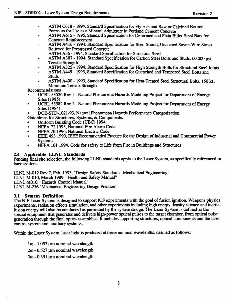
ASTM C618 -1994, Standard Specification for Fly Ash and Raw or Calcined NaturalPozzokm for Use as a Mineral Admixture in Portland Cement ConcreteASTM A615 -1995, Standard Specification for Deformed and Plain Billet-Steel Bars forConcrete ReinforcementASTM A416 -1994, Standard S~ification for Steel Strand, Uncoated Seven-Wire StressRelieved for Prestressed ConcreteASTM A36 -1994, Standard Specification for Structural SteelASTM A307 -1994, Standard Specification for Carbon Steel Bolts and Studs, 60,000 psiTensile StrengthASTM A325 -1994, Standard Specification for High Strength Bolts for Structural Steel JointsASTM A449 -1993, Standard Specification for Quenched and Tempered Steel Bolts andStudsASTM A490 -1993, Standard Specification for Heat-Treated Steel Structural Bolts, 150 ksiMinimum Tensile Strength
Recommendations● UCRL 53526 Rev 1- Natural Phenomena Hazards Modeling Project for Department of Energy
Sites (1985)● UCRL 53582 Rev 1- Natural Phenomena Hazards Modeling Project for Department of Energy
Sites (1984)● DGE-STD- 1021-93, Natural Phenomena Hazards Performance CategorizationGuidelines for Structures, Systems, & Components.● Uniform Building Code (UBC) 1994● NFPA 721993, National Fire Alarm Code● NFPA 701996, National Electric Code● IEEE 4931990, IEEE Recommended Practice for the Design of Industrial and Commercial Power
systems● NFPA 1011994, Code for safety to Life from Fire in Buildings and Structures
2.4 Applicable LLNL StandardsPending final site selection, the following LLNL standards apply to the Laser Systen as specifically referenced inlater sections.
LLNL M-012 Rev 7, Feb. 1993, “Design Safety Standards -Mechanical Engineering”LLNL M-O1O,March 1989, “Health and Safety Manual”LLNL MO1O,“Hazards Control Manual”LLNL M-256 “Mechanical Engineering Design Practice”
3.1 System DefinitionThe NIF Laser System is designed to support ICF experiments with the goal of fusion ignition. Weapons physicsexperiments, radiation effects simulation, and other experiments including high energy density science and inertialfusion energy will also be conducted as permitted by the system design. The Laser System is defined as thespecial equipment that generates and delivers high-power optical pulses to the target chamber, from optical pulsegeneration through the final optics assemblies. It includes supporting structures, optical components and the lasercontrol system and auxiliary systems.
Within the Laser System, laser light is produced at these nominal wavelengths,defined as follows:
101-1.053 ~m nominal wavelength
20-0.527 pm nominal wavelength
3(0 -0.351 ym nominal wavelength

NW - SDRCK)2- Laser System Design Requirements Revision 2
.
3.1.1 System DescriptionThe Lase~system is conf@red in a four pass architecture with a laser pulse injection into the output Spatial Filter.The beams are arranged in groups of contiguous beams packed in an may that is four beams high. A total of192 beams will be deployed. The master oscillator in pulse generation creates an initial optical signal which istemporally shaped and distributed to individual beam line amplifiers. The preamplifier is a compact standalonepackage with a nominal gain of 101O.It also spatially stages and provides the aperture which is optically relayedthrough the remainder of the laser optical system. The beam is thea injected into the far field of the transportspatial falter,which directs the beam through the boost and cavity amp~lers in a multi-pass scheme that minimimsthe energy required for initial injection. The nominal hard aperture size is 40 cm a compromise between risk andsystem cost. Amplifier flashlamps uniformly pump the amplifier slabs. The power conditioning system providingthis power utilizes banks of dielectric capacitors. Switch-out of the pulse from the amplifier cavity is accomplishedwith the Plasma Electrode Pockels Cell (PEPC) switch that operates at high efficiency.
After passing through the booster amplifler and transport spatial falter the la beams are directed to the targetchamber using a number of high-reflectivity mirrors. At the chamber the beams are directed to either an inner orouter cone array. Clustered into groups of four contiguous beams, they are directed through the final opticssystem. Within each final optic system the frequency of each beam is tripled by using a KDP crystal and a KD*PcrystaI, then focused onto the target with the focusing lens. After the beam is focused, it is then phase modulatedusing a kinoform phase plate prior to target inadiation.
During the transport of each laser beam from the preamplifier to the targe~ precision systems provide for the beamalignment, and the measurement of beam spatial and temporal characteristics.
Optical components of the laser system comprise those large, custom designed and fabricated for amplification andtransport of the full aperture NIP beam. Included in this category are; laser slabs, injection, cavity and transportmirrors, optical switch crystals and polarizer, spatial falter lenses, frequency conversion crystals, vacuumwindows for the Pockels cell, focus lens and the debris shield/phase plate.
The Laser is composed of elements of five Level 2 WBS systems. The level 3 WBS elements which are coveredby this SDR document are listed below, and are functionally described in Section 3.1.5. Note that not all LaserLevel 3 WBS elements have been designated major subsystems for the purpose of controlling Laser Systemconfiguration requirements.
1.3.1 Optical Pulse Generation System1.3.2 Amplifier System1.3.3 Pockels Cell System1.3.4 Amplifier Power Conditioning System1.3.5 Laser Auxiliary Systems
1.4.1 Beam Transport Enclosures1.4.2 Interstage Subsystems1.4.3 support structures1.4.4 Optomechanical Systems
1.6.1 Amplifier Slabs1.6.2 Lenses1.6.3 Mirrors1.6.4 Polarizers1.6.5 KDP and KD*P crystals
1.6.6 Debris Shields and Windows1.6.7 Pulse Generation Optics
.
1.7.1 Alignment Systems
9

‘
NIF - SDRO02 - Laser System Design Requirements Revision 2
,
1.7.2 Beam Diagnostics1.7.3 Wavefront Control Systems
1.8.7 Final Optics Assemblies
3.1.2 System FunctionsThe overall functions of the Laser System are listed below. Specific requirements are listed in Sections 3.2-3.6.
●
●
●
●
●
●
9
●
Provide capability to routinely produce a highquality, 1.8 MJ, temporally-shaped optical pulse at 30frequency, incident on the entrance hole of the target hohlraum.
Provide capability of producing a pulse with peak power of at least 500 TW.produce laser-wavelength of 0.35 micro-meters (pm).Provide for an RMS deviation in power delivered by the beams horn the power specified, averaged over
any 2 nanoseconds (ns) time interval, of less than 8%.Provide abeam pointing accuracy with RMS deviation of less than 50 pm in the target plane.Capable of producing a pulse with overall duration of up to 20 ns in an individual beamline.Provides capability of delivering pulses to the fusionharget with a dynamic range of at least 50:1, where
dynamic range is defined as the ratio of intensity at the peak of the pulse to the intensity in the initial “foot”portion of the pulse.
Provide for focusing of the beam onto the target.
The functions of the major subsystems of the Laser are described in Section 3.1.5, Major Subsystems of thisdocument.
3.1.3 System Diagrams
3.1.3.1 System Operating ModesFigure 3.1.3.1-1 identifies the sequence of operating modes planned for the NIF facility. The laser system willalso operate in all these modes, following the same scenario as the overall facility.
10

NW - SDRO02 - Laser System Design Requirements Revision 2
I I●
Consauct?wAssemble
Commission . pRc-shot
setup &“~Acceptance
test
Operations
Figure 3.1.3.1-1 NIF operating modes.3.1.4 Primary InterfacesThe Laser system has major interfaces witlx
Laser and Target Area Building WBS 1.2.2.1/2 - The Laser interfaces with the Laser Building in the generalarrangement, at physical support points, environmental control, in provision of utilities, in installation,operation and maintenance.
Optics Assembly Building WBS 1.2.2.3- The Laser System components are received, inspected, cleaned,assembled, tested and stored in the Optics Assembly Building..
Integrated Computer Control, WBS 1.5- The computer controls provide timing and control signals, alignmentand supervisory control for target area systems. The laser systems provide various diagnostic data to theintegrated controls.
Target Experimental Systerm WBS 1.8- The laser system interfaces mechanically with the target area systemat the mounting points for the final optic assembly and Beam Transport mirrors in the Target Area. The laserprovides laser energy with appropriate properties for conducting experiments. The Target Area Systemprovide diagnostics of target performance, experimental targets, and physical support for final opticassemblies.
Interface Control Documents (ICDs) describe the functional and physical interfaces between WBS Level 3subsystems, and are controlled separately from System and Subsystem Design Requirements (SDRS and SSDRS).ICDS control: 1) interfaces between subsystems which are both within the Laser System, and 2) interfacesbetween subsystems within the Laser System and subsystems outside the Laser System. The document controlsystem will contain the approved list of ICDS and the present revision of each.
11

NIF - SDRO02 - Laser System Design Requirements Revision 2
.
Site Fscilitiss(SDROO1) *
‘(7rGii-i%;iiiti&Z&&-t3-’~Contdedenvironment :
:coovetMiod Iutilitia ,~pltysicdsttppcaK3aBmvimnmm I
:
Lift capability !1
~ L. . . . ..r . .....i
fik%t ‘&-t;F-x-ii%&i’ - Ik?atbsds ~~Weights a1 I# ,eo I, aI 11 1I 1..-. ..— . . . . . . .
t
hi bsds #:Weights t
s:n.gsmtstefsdiatiott :-tMixed WSSSSstreamI i
3LaserSystem(SDROOZ)
II
(fromT@. EXP. SYS. to
~bter) Afigmnent tefssutcf
&aefdisgmskdsts
~BdsatHd light
Debris
~ I !. . . . . . . . . .-..4 -------
8
. . . . . . .
t
fi7m-miiit-CYG%isl&---7~(.&-.~-G.=.).
# :conllol&timittg:F-) 1;Atxessmntml : :ust!r~!F~@ SySMIM -1 : *! Dssssmftiving
mu L4ds I : SsfSty control
!Weightstal
I I 1t I 1..-. ..— ------- ..-----. ......
:Continued●ovi&menl 1: Collvsmionslmilitia ,@
* I f’%w’%ny
i
:imoment
Lift C4usbility !:Redist&Shiading I
t-.......—. . . . . .
=9: 1
It t, 01 I1 1I-.. -.. . ..— . . ..-U’
n~Terget Exfxtimetttd Sy(sDRa13)
f!~&-&.=rG ~... ~
: @ w1I
:coottd&timistg :~ ~userlmafsce ~
*lMssm&Ving In:Ssfelywad ,I ni i. ..--. ..— -..--
u-----------:(–Kti-&sr to tot Coltttols) I
iststus &diegndcdsfs !! !
*: ia
#t, ,
t 1I 1I—.......-—— .-
U’
i i,.!—......-—. .
u
en~c~Coou’ois(SDRO04)
NIF Sys!.em Fundkuml Rd81ion8MpDhgrAul(HosizomdarmwssmouIPI@ Vetticslasmwsm’eitIPuts)
F@re 3.1.4.1- Functional Relationship Diagram
3.1.5 Major SubsystemsThe Laser System is composed of thirteen major elements:
Optical Pulse Generation SystemAmplifier SystemPockels Cell SystemAmplifier Power Conditioning SystemLaser Auxiliary SystemsBeam Transport EnclosuresInterstage Subsystemssupport structuresOptomechanical SystemsAlignment SystemsBeam DiagnosticsWavefront Control SystemsFinal Optics Assemblies
3.1.5.01 Optical Pulse Generation System WBS 1.3.1 & 1.6.7The Optical Pulse Generation (OPG) System produces the lo, temporal and spatial smoothed foxmatted pukeswith the correct energetic and optical characteristics .~uired for injection into the main amplifier TransportSpatial Filter on an individual bearnline basis. The uut.mlpuke is generated by the master oscillator, temporallyshaped in the amplitude modulator and transferred to each preamphfier module (PAM) via fiberoptic cable. The
12

NIF - SDRO02 - Laser System Design Requirements Revision 2
PAM is a two-stage amplifier consisting of a regenerative amplifier stage followed by a beam shaper spectraldispersion smoothing section and a multi-pass cavity. The pulse is optically matched (e.g., VNumber, focuslocation, image relay, etc.) to the main amplifier and spatially filtered by the preamplifier beam transportsubsystem (PABTS).
Functions of the optical Pulse Generation System
● Generate and deliver to the main laser cavity injection point, on an individual beamline basis, optical pukeswith the following characteristics:- a wavelength at which the laser gain is maximum (approximately 1.053 pm)
variable pulse lengthsspatial shaping capability
- gain sufficient to amplify with high fidelity the spectral, temporal and spatial signals generated to theseveral Joule level
optically transport and format the beam to meet the basic optical system requirements of the mainamplifier (e.g., wavefiont, beam shape, f/Number, focus location, image relay, polarization, andspatial-intensity-profde orientation).
● Provide a pulsed, several milliwatt beam on a continuous basis to the laser system for component alignmentand beam diagnostics calibration purposes.
s Provide a “typical drive pulse” of several joules energy to the laser system for component alignment andbeam diagnostics calibration purposes.
“ Adjustable output energy and temporal pulse shape to allow for balancing of the beamline outputs.. Variable beamiine intensity profile to compensate for gain roll-off in specific bearnlines due to geometric
factors in the two dimensional packing of bearnlines in a beam bundle.“ Adjustable time delays for each beam line to allow synchronization of pulse arrival times on target.“ Produce temporally and spatially shaped and sequenced pulses on specified beamlines for target
backlighting applications.
3.1.5.02 Amplifier System WBS 1.3.2 & 1.6.1The Amplifier consists of the hardware required to provide laser gain (increased optical pulse energy). It includesthe mechanical assembly to support the Nd glass slabs, blast shields, covers for operational protection, thereflectors and the flashlamps. The Pulse Power needed to drive the lamps is covered in the Power Conditioningsection.
Anmlifier svstem fimctionsL
●
●
●
●
Provide for the efficient pumping of the laser slabs by the flashlamps.Provide necessay gain of the required spatial uniformity, and mitigates the spatial amplitude variations in
the beam.Provide a mechanically stable housing that allows for ease of maintenance.Allow for contamination control in the pump cavity.
13
.
NIP - SDRO02 - Laser System Design Requirements Revision 2
.
3.1.5.03 Pockels Cell System WBS 1.3.3, 1.6.5.1 & 1.6.6.3The Pockels Cell Assembly working in conjunction with the Polarizer, fi.mctionsas the optical switch in the mainamplifier cavity. During a laser shot, the switch is closed by turning the Pockels cell on, which captures the opticalpulse in the amplifier cavity allowing for multipass amplification. When the Pockels cell is in the “on” state, thepolarization of the light allowed to pass through it is rotated 90 degrees. This aligns the light polarization with thepolarizer. The beam then passes through the polarizer toward the second cavity end mirror, reflects off the mirror,and returns to the amplifiers for additional gain passes. During the final pass, the switch is opened by turning thePockels cell off. The polarization of the beam is not rotated so the beam now reflects off the polarizer and isreflected out of the amplifier cavity.
Pockels Cell Functions:. When turned on, the Pockels Cell assembly rotates the polarization of a linearly polarized incoming beam
by 90 degrees.“ When turned off, the Pockels Cell assembly does not alter the polarization of the incoming beam.
3.1.5.04 Amplifier Power Conditioning System WBS 1.3.4The Power Conditioning system provides pulsed electrical power to drive the flashlamps in the laser cavity andbooster amplifiers. Electrical energy tlom the utility power line is converted to stored energy in high voltagecapacitors over a period of roughly one minute. High power switches and transmission lines then discharge thecapacitors with a specified pulse shape into the flashlarnps.
The Power Conditioning system functions are:“ Provide electrical pump energy to flashhunps in the laser arnp~lers including capacitor charging, energy
storage, switching, and power transmission● Provide adjustment of pump energy over speeified range“ Pre-ionize flashlamps a few hundred microseconds prior to a shot● Provide low energy “lamp cheek shots to verify system integrity● Provide controls and diagnostics for the following functions:
charging suppliessafety energy dump system, interlock permissivetiming delays and triggeringlamp curnmt diagnostics during both normal and “lamp check” shotssystem diagnostics and maintenance
3.1.5.05 Laser Auxiliary Systems WBS 1.3.5Laser auxiliary systems provide low conductivity water, electrical support, compressed air and working gasrequired for lader system operations. They also provide an inventory and control system designed to keepreplacement parts readily available to reduce downtime as well as personnel transporters for maintenance andrepair access in hard to reach areas of the laser system. An impoxtant element of the laser auxiliary systems is theclean gas system which is essential to the proper function of the Amplifiers.
Laser auxilkuy systems functions include:s Provides support elements for laser system function and operability.c AUOWSpersonnel access to otherwise inaccessible areas for repair and maintenance of the system by use of
personnel transport systems, i.e.: hydraulic manlift.s Provides a clean gas supply for the proper function of internal ~plifier components.
14

,
NIF - SDRO02 - Laser System Design Requirements Revision 2
.
3.1.5.06 Beam Transport Enclosures WBS 1.4.1The Beam Transport Enclosures consist of beam tubes or vessels that contain the laser beam from beam injectionat the transport spatial falter to the target bay wall. Beam transport enclosures include the transport and cavityspatial filters, the interstage beam enclosures, and the switch yard beam enclosures. Sections of the enclosuresmay be under vacuum or filled with noble gas to prevent stimulated rotational rarnan scattering (SRRS).
The functions of the beam transport enclosures are to:safely contain laser beam within an appropriately controlled environment to minimke temperature induced
density gradients and practice contamination.provide access for optomechanical system maintenance and removal of optic assembliesprovide ports for beam injection and diagnosticsprovide required stability for optics mounting
3.1.5.07 Interstage Subsystems WBS 1.4.2Interstage Subsystems (Beam Transport Auxiliary Systems) provide utilities, vacuum systems, local rigging, localclean rooms, and optics handling systems.
Beam transport is accomplished by propagation through beam tubes. InterStage subsystems maintain the gaseousenvironment in the switchyard beam tubes and the evacuated environment in the spatial falters. Clean backfillsystems are also provided for spatial falters, providing control of temperature and particle contamination.
Switchyard beam tubes will be filled with a noble gas to prevent stimulated rotational raman scattering (SRRS).The temperature of the gas in these tubes will be controlled to the level of the facility temperature and deliveredsufficiently clean so that overall optics cleanliness requirements are met.
3.1.5.08 Support Structures WBS 1.4.3The Laser and Beam Transport Structural Support Systems (LBTSSS) support the hardware that transports thebeam through to the target chamber area. The beams are arranged in 4 x 2 groups in the laser area, and split into2 x 2 groups in the switchyards. Each beam has an independent, turning mirror for every turn required.Amplifiers, polarizers, mirrors, pockels cells, and spatial falters are contained in assemblies which, in turn, attachto the WBS 1.4.3 support structures.
The support structures;c Mechanically support beam tubes, and optomechanical systems.● Provides a support structure that maintains high, positional stability.
15

NIF - SDRO02 - Laser System Design Requirements Revision 2
*
~1.f~96 ~Beam Transport Optomechanical Systems WBS 1.4.4, 1.6.2, 1.6.3, 1.6.4, 1.6.6.2
The s&iai f~ter is a confocal lens pair with a pinhole.l.pcatedin their common focal plane. The beams lowfrequency spatial modes pass through the pinhole w~e the high frequency modes are removed by the regionexterior to the pinhole. Laser alignment and diagnostics are accomplished in the transport falter. The preamplifierlaser pulse is injected into the transport falter.
The optical pulse generator delivers the input beam through a vacuum window in the Transport spatial falter.Thespatial filter then utilizes a system of small aperture optics to route the input beam through the spatial falterpinhole,and into the amplifier cavity.
The cavity rnimr mount assemblies, located at both ends of the laser cavity, provide support and remotealignment of the cavity mirrors. These mimrs reflect the beam back and forth to accomplish multi-passamplification. The transport turning-mirror mounts provide support and alignment of the mirrors that transport thebeam from the laser cavity to the target. The NJF polarizer mount assembly provides support and remotealignment of the polarizer plate at Brewster’s angle. The polarizer plate works in conjunction with the Pockels ceilto switch the beam out of the laser cavity after four-pass amplification.
Cavity Mirror Mount Assemblies● Provide support and remote alignment of the cavity mirrors.● These mirrors reflect the beam back and forth to accomplish multi-pass amplification.
Transport Turning Mirror Mounts“ Provide support and remote alignment of the transport mirrors.“ The mirrors transport the beam fkom the laser cavity to the target.
Polarizer Mount Assembly● Provides support and remote alignment of the polarizer plate at Brewster’s angle.● The polarizer plate works in conjunction with the Pockels Cell to switch the beam out of the laser cavity
after four-pass amplification.
Spatial filter optical assemblies:
The functions of the spatial filters are:● Allows for removal of high spatial frequency modes to reduce the risk of darnage to the large,
expensive optics.● Provides the beam dump for abso@on of excess beam energy.s Provides small aperture locations for laser alignment and diagnostics.“ Provides a method for injecting a low energy pulse into the high-gain amplifier cavity.
16
NIF - SDRO02 - Laser System Design Requirements Revision 2
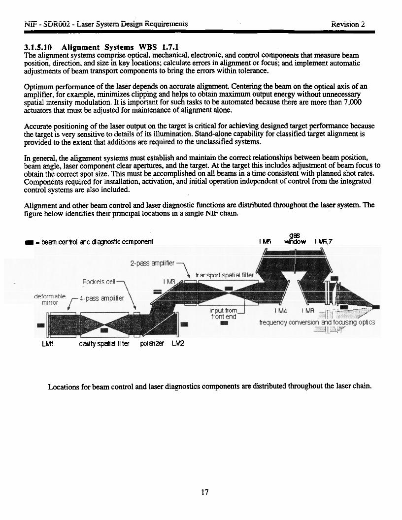
3.1.5.10 Alignment Systems WBS 1.7.1The alignment systems comprise optical, mechanical, electrordc, and control components that measure beamposition, direction, and size in key locations calculate errors in alignment or focus; and implement automaticadjustments of beam transport components to bring the errors within tolerance.
optimum performance of the laser dependa on scarrate alignment. Centering the beartr on the optical axis of anamplifier, for example, minimizes clipping and helps to obtain maximum output energy without unnecessaryspatial intensity modulation. It is important for such tasks to be automated because there are more than 7,0CXIactuators that must he adjusted for maintenance of alignment alone.
Accurate positioning of the laser output on the target is Critical for achieving designed target performance becausethe target is very sensitive to details of its illumination. Stand-alone capabtity for classified target alignment isprovided to the extent that additions are required to the unclassified systems.
frrgeneral, the alignment systems must establish and maintain the correct relationships between beam position,beam angle, laser component clear apertures, and the target. At the target this includes adjustment of beam focus toobtain the correct spot size. This must be accomplished on alf beams in a time consistent with planned shot rates.Components required for installation, activation, and initial operation independent of control from the integratedcontrol systems are also included.
Alignment and other beam control and laser diagnostic functions are distributed throughout the laser system. Thefigure below identifies their principal locations in a single IWFchain.
- = bean coriol arc demostlc ccrnpment IwlJi35w , ~ ~
LMl cawtyspdisl filter @mm LM2
Locations for beam control and laser diagnostics components are distributed throughout the laser chain.
17

NTF- SDRO02 - Laser System Design Requirements Revision 2
*
3.1.5.11 Beam Diagnostics WBS 1.7.2The beam diagnostics comprise optical, mechanical, electronic, and data processing components that measure laserenergy, power, and spatial intensity distribution in key locations.
These measurements provide the basis for tuning the laser to produce the precise output characteristics required byeach target. Automated comparisons between the achieved performance and the desired results define the set ofadjustments to be implemented before the next shot.
Accurate measurement of beam characteristics is also important for proper modeling of target experiments sincetarget performance is very sensitive to details of its irradiation. To the extent possible, it is desirable to measure theproperties of each beam going to the target on each target shot.
Processing of the data collected on each shot must be accomplished quickly enough to provide feedback foradjustment prior to the next shot at the maximum shot rate.
3.1.5.12 Wavefront Control System WBS 1.7.3The wavefront correction systems comprise optical, mechanical, electronic, and control components that measurethe wavefi-ontat the output of each laser chain, calculate the error by comparing the measured and desiredwavefronts, and implement automatic adjustments of the deformable mirror to bring the errors within tolerance.
Optimum performance of the fkequency converter and proper focusing of the beam on the target depend onmeeting wavefhnt requirements. The adjustment of even one deformable mirror by an operator is difllcuit andfor a 192-bearn system the task must be automated.
Optimization of the wavefront for each shot is based partiy on current information and partiy on information fromprevious shots. Correction for static enms due to fabrication, slowly varying thermally induced emors, and errorsdue to gradients in the gas path through which the beam is propagating is based on real-time measurement in theperiod before a shot. Correction for ampiifier abmations induced at shot time is based on measurements of theseeffects from previous shots.
3.1.5.13 Final Optics Assemblies WBS 1.8.7, 1.6.2.3, 1.6.5.2, 1.6.5.3, 1.6.6.1, 1.6.6.5,1.6.6.6The final optics system includes all mounting hardware, 2-axis precision positioners for the KDP crystals, a z-axistranslation stage for each lens, and all support structure required to maintain high positional stability of the opticsat the target chamber.
The Final Optics system converts lo beams to the third harmonic through use of KDP/K.D*P frequencyconversion crystals that are mounted in partial vacuum within the final optics tubes attached to the target chamber.
After passing through a vacuum barrier window, the 10 input beam is converted to 1(o,20, and 30 by the KDPcrystals. After conversion, each beam passes through a 700 cm focal length lens and finally the debris shield. Akinoform phase plate conditions each beam. Each of the four contiguous beams are transported in a group andfocused to the same location near the target. The wedge in the focus lens bends the 10 and 2cDresidual light awayfrom the target laser entrance hole preventing unwanted light in the target
18
.
NIF - SDRO02 - Laser System Design Requirements Revision 2
*
Final @iCS Functions;
●
●
●
●
●
●
3.2
Converts 10 beam frequency to the third harmonic (30).Provides for mounting of the focal lens, debris shields and kinoform phase plate facilitating beam
smoothing.Disperses the 10 and 2tDresidual beams keeping them from entering the target laser entrance hole.
Conditions the 30 beam.In conjunction with Final Focusing Lens, focuses each of the four beams onto a common focal area
near the target.Provides a vacuum btier for the target chamber,
Requirements and Verification
3.2.1 Performance Characteristics
3.2.1.01 Laser Energy and Power
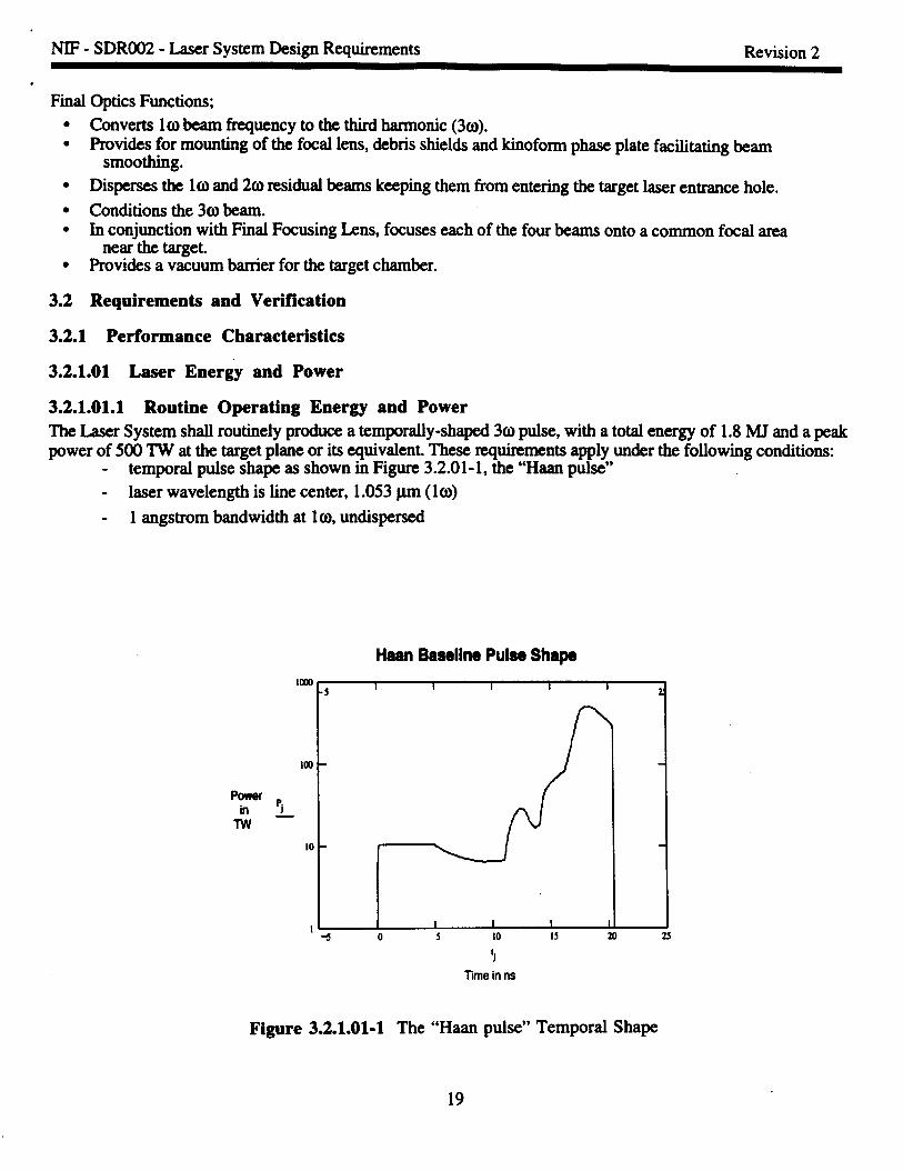
3.2.1 .01.1 Routine Operating Energy and PowerThe Laser System shall routinely produce a temporally-shaped 3copulse, with a total energy of 1.8 MJ and a peakpower of 500 TW at the target plane or its equivalent. These requirements apply under the following conditions:
temporal pulse shape as shown in Figure 3.2.01-1, the “Haan pulse”
- laser wavelength is line center, 1.053pm (10)
- 1 angstrom bandwidth at lo, undispersed
Haan Baaeline Puiae Shape
moo-5 I I I I I
2!
la) -
Pj—
m -
I1 I 1 I
* o 5 10 15 20 25
1.1
Time inns
Figure 3.2.1 .01-1 The “Haan pulse” Temporal Shape
19

NIF - SDRO02 - Laser System Design Requirements Revision 2
,
3.2.1 .01.2 Maximum Design Energy and PowerThe laser shall be capable of producing a temporally-shaped 30 pulse with a total energy of 2.2 MJ and a peakpower of 600 TW at the target plane or its equivalent. These requirements apply under the same conditions as3.2.1.01.1.
3.2.1 .01.3 Operating Energy and Power Envelope
The Laser System shall be capable of routinely producing any combination of 301power and energy within theshaded region of Figure 3.2.1.01.3-1, within the norm-shot-to-shot turn-around-time.
-.
I #
l“’’’’’’’’’’’’’’’’’’’’’’”(500pm
600 “/
I-1
2m
0.0 0.5 1.0 1.5 2.0 2.5 3.0
Total UV Ul~y (MJ)
Figure 3.2.1 .01.3-1 Laser System 30 Power/Energy Envelope.
3.2.1.02 Laser Pulse WavelengthThe wavelength of the laser pulse delivered to the target shall be 0.35 I.Lm.As a design goal, the laser should notpreclude delivering 0.53 pm and 1.053pm wavelength light to the target with straightforward modifications.
3.2.1.03 10I Wavelengths
The lW laser shall provide light at the wavelength of maximum gain, 1.053 p.m.The design shall not preclude
future implementation of multi color wavelength operation at up to four separate lCI)wavelengths from 1.0523-1.0553 pm.
3.2.1.04 Power BalanceThe rms deviation in the power delivered by a laser beam from the specified power shall be less than 8% of thespecified power averaged over any 2-ns time interval.
20

NIF - SDRO02 - Laser System Design Requirements Revision 2
,
The total energy delivered by the system (all fd beams) shall be within +3% of that specified. The simultaneityof beam arrival at target chamber center shall be + 30 ps.
3.2.1.05 Beam Positioning Accuracy and StabilityThe rrnsdeviation in position of the centroids of all beams from their specified aiming points shall not exceed50 microns at the target plane or its equivalent. The Laser System interacts with the Target Experimental Systemto collectively meet the pointing accuracy and alignment stability requirements. Allowed inaccuracies andinstabilities are allocated to key subsystems, and are defined in appropriate SSDR documents,
3.2.1.06 Laser Pulse DurationThe laser shall be capable of illuminating targets with laser pukes of 500 ps to 20 ns duration, with power andenergy within the overall operating envelope. The Laser System shall be capable of diagnosing optical pukeslonger than 1 ns in the target chsmber for each beam. The Laser System shall further be capable of diagnosingpulses of any duration within the above-stated range from individual beams at sn equivalent target plane.
3.2.1.07 Laser Pulse Dynamic RangeThe laser shall be capable of delivering pulses to the fusion target with dynamic rangeofatleast501, whe~dynamic range is defined as the ratio of intensity at the peak of the pulse to the intensity in the initial portion of thepulse.
3.2.1.08 Capsule Irradiation SymmetryThe Laser System shall provide appropriate target irradiation symmetry for indirect-drive experiments as definedbelow. The Laser system shall not preclude future upgrade to achieve the direct-drive irradiation symmetrydescribed below.
For indirect-drive experiments, the laser shall provide two-sided laser illumination of the hohlraum. Multiple laserbeams on each side shall enter the hohiraum sJong two concentric cones with cone half-angles of approximately 27degrees and 48 degrees, and with two-thirds of the beams on the outer cone and the remainin g one-third on theinner cone. Each cone shall consist of 8 or more 4-beam “quads”.
‘ For direct-drive experiments, the Laser System shall not preclude the addition of a third cone of beams, concentricwith the two indirect-drive cones, but with a cone half-angle of approximately 77 degrees, and containing half ofall the beams. For this mode of operation, the 27 degree and 48 degree cones would have one-sixth and one-thirdof the beam respectively. In order to not pnxlude this option, the Laser System, in concert with all other NWsystems, shall provide a conceptual design for the required beam transport to the target chamber and ensure thatthis transport can be accomplished by nmranging existing indirect-drive components or adding additionalcomponents.
3.2.1.09 Pre-pulse PowerThe 30 laser intensity delivered to the target LEH during the 20-ns interval prior to arrival of the shaped laserpulse shall not exceed 1~ W/cm2.
3.2.1.10 Laser pulse Spot SizeThe laser spot size for any individual beam shall be 500 ~ to be defined as follows: De envelope of the laserpulse spatial intensi
Tdistribution shall approximate an eighth order super-Gaussian at best focus. The laser beam
profde diameter at e- in intensity shall not exceed 500pm, with 1.8 MJ (total for all beams) of pulse energycontained within a circle of 600-pm diameter at the target plane or its quivalent. The irradiance on the perimeter oroutside the perimeter of a 3 mm diameter Laser Entry Hole should be less than 1014W/cm*.
21

NIF - SDRO02 - Laser System Design Requirements Revision 2,
3.2.1.11 Beam SmoothnessThe NIF shall have flexible beam smoothing capability for the suppression of laser plasma instabilities in indirectdrive targets and potentially for the suppression of hydrodynamic instabilities if utilized for direct drive targets.The capability shall include:
● phsse plates at the output of the laser for the control of the spatial irradiance distribution on the target.s lD-Smoothing by Spectral Dispersion (SSD), 3 angstrom of bandwidth critically dispersed, with means for
bypassing beam conditioning subsystems.● not to preclude 2D-SSD with 5 angstrom of bandwidth critically dispersed, with means for operating with
lD-SSD as described above, and with means for bypassing beam conditioning subsystems.“ not to preclude operation at up to four different wavelengths with 1-D SSD, 3 angstrom of bandwidth
critically dispersed or with beam conditioning subsystems bypassed.
3.2.1.12 Annual Nu’mber of Shots with Fusion YieldThe Laser System shall be capable of performing yield shots with a total DT fusion yield of 1200 M.T/year.TheLaser System shall be capable of performing up to 50 shots per year with a routine DT fision yield of 20 MJ.
3.2.1.13 Shot Turn-Around TimeThe shot turn-around time for Laser System shall be no more than 8 hours for no-yield shots. The Laser Systemshall not preclude future upgrade to achieve a shot turn-around time of 4 hours for no-yield shots. The shot turn-around time is defined as the minimum time required after a Ml-system, no-fhsion-yield shot until the next shotcan be taken. (It includes the time required to recover from a shot perform maintenance that is nx@red betweenevery shot, prepare the system for a shot (including laser alignment and target insertion and alignment), and thenactually execute the shot. This does not include the time for unplanned maintenance or for periodic shutdowns forplanned maintenance.)
3.2.1.14 Diagnostic Instrument Capabilities to Verify Laser PerformanceThe Laser System shall have the following measurement capabilities which are required to verify the PrimaryCriteria and Functional Requirements:
●
●
●
●
●
●✎
●
Measurement of the laser pulse energy and power.Measurement of the laser pulse duration and dynamic range.Measurement of laser beam power balance.Measurement of the simultaneity of amival of pulses from individual beamhnes at target chamber center.Measurement of the laser beam pointing accuracy.Measurement of laser prepulse intensity.Measurement of laser pulse spot size.Measurement of laser pulse smoothness.
3.2.1.15 Laser Firing FlexibilityAs a &sign goal, the Laser System should provide maximum flexibility in the timing, sequencing, and temporalpulse shaping of separate laser beams.
3.2.1.15.1 Bundle Firing FlexibilityThe Laser System shall be capable of firing an arbitrtuy operatordesignated subset of the bundles on each shot,within the overall restriction of the shot turnaround time for each bundle or beam.
22

NIF - SDRO02 - Laser System Design Requirements Revision 2
,
3.2.1 .15.2 Beam Firing FlexibilityThe Laser System shall be capable of producing pulses from the four vertical pairs of beams within a given bundleat separate times, within an overall time window of 100 ns.
3.2.1.15.3 Beam Pulse Shape FlexibilityThe laser shall be capable of producing an operator-selected temporal puke shape for each be- within theoverall operating envelope defined by other sections of this document, independent of all other beams.
3.2.1 .15.4 Laser Bay Operating FlexibilityThe laser system shall have the capability to fn laser beams in one laser bay with simultaneous safe mannedaccess in the other laser bay and in the target area. For this requirement, “safe manned access” includes personnelphysical access to the non-operating laser bay, power conditioning and target areas, the ability to work on allhardware in the non-operating laser bay, power conditioning and target areas, and the ability to work in the opticalbeam paths in the non-operating laser bay and target area.
3.2.1.16 Beam Focusing and Pointing FlexibilityThe Laser System shall routinely place beam spots at arbitrary operator-designated positions within ~ 30 mm ofthe target chamber center in time directions. The Laser System shall have the capability to routinely placesubaperture beam spots at arbitrary operator-designated positions within f 50 mm of the target chamber center inthree directions, with minor modification. The Laser System shall be capable of placing beam spots at arbitraryoperator-designated positions within * 250 mm of the target chamber center in three directions, with future user-provided modifications of the final optic assemblies.
23

NW- SDRO02 - Laser System Design Requirements Revision 2
3.2.1.17 Management of Unconverted (l@ and 2oI) Light
The unconverted lm and 20 light shall be managed in the target chamber so as not to adversely affect the operationof the system or the experimental physics.
The fd optics shall divert the unconverted 10 light so that its geometrical optics edge is displaced at least
3.0 mm from the center of the LEH. The final optics shall divert the unconverted 2colight so that its geometricaloptics edge is displaced at least 1.76 mm from the center of the LEH.
5.90 mm
m
(hohlraum)
3c0\
2.95 mm(LEH)
1.76 mm
3.00 mm
Figure 3.2.1 .17-1 Nearest allowed location of unconverted 10 and 201light at the target.
3.2.1.18 Optical Clear ApertureThe optical clear aperture of the amplifier shall he 400 mm x 400 mm.
The optical clear aperture of the frequency tripler shall be 400 mm x 400 nmx this is the limiting optical clearaperture in the final optics.
3.2.1.19 Number of BeamsThe Laser System shall be composed of 192 beams.
24
3.2.1.20 SRRS Suppression
NW- SDRO02 - Laser System Design Requirements Revision 2
,
The laser system shall scatter no more than 1% of the 10 power into Rotational Rarnan lines during transport fromthe output of the final spatial filter to the final optics assembly.3.2.1.21 Low-Power and Low-Energy Laser PulsesThe laser system shall be capable of ffig low-power and low-energy laser pulses without damage to any lasersystem components except beam dumps. Low-power and low-energy is defined for this requirement as includingshots in which the flashlamps are f- but no input pulse is injected.
3.2.1.22 Experiment Compatibility
3.2.1 .22.1 Classification Level of ExperimentsThe Laser System shall allow both classified (at the SRD level) and unclassified experiments. The Laser Systemshall provide for alignment of classified (SRD) targets. As a design goal, the Laser System should minimize thecost and operational impact of changing classification levels.
3.2.1 .22.2 Future Upgrades for Other Users
3.2.1 .22.2.1 Future Additional Target ChamberThe design of the Laser System shall not preclude the future installation of an additional target chamber,employing all laser beams, for weapons physics and/or radiation effects testing. As a part of the NTFprojec~ theLaser System, in concert wk.h other NW systems, shall provide a general arrangement layout for the addition ofthe target chamber. All Laser System designs shall be compatible with this design concept. All structural elementsshall provide clearance for the identified future laser beam paths. Certain structures, such as building skins orshielding walls, require integrity to fulfill their functions prior to addition of the Iitwe target chsmbe~ clearancefor future beams is not required through such structures. However, their design shall be adequate that they willmeet their requirements after addition of the future target chamber and associated beam clearances.
3.2.1 .22.2.2 Radiation Effects Testing CapabilityThe baseline Laser System design shall incorporate basic capabilities so as not to pnxlude radiation effixts testingby DNA or DOE, with future upgrade.
3.2.1 .22.2.3 Other User NeedsAs a design goal, the Laser System should accommodate requirements of other users with diverse needs.
3.2.1.23 Laser System Grounding SystemThe Laser System shall comply with the NIF Grounding Plan,NIF-LLNL-94-211, L-17346-1. Laser Systemcomponents in the laser bay shall be isolated from those in the target bay, and separately grounded.
.
3.2.2 Physical Characteristics
3.2.2.1 General Arrangement
3.2.2.1.1 Laser System ArchitectureThe laser system shall incorporate the following basic architecture:
a. master-oscillator, power-amplifier systemb. conditioned pulses from master oscillator injected into the transport spatial filter near pinhole planec. four-pass ampliilcation in cavity, with switch to allow pulse to enter and exit cavityd. image relaying from serrated aperture
25

NW - SDRO02 - Laser System Design Requirements Revision 2
,
3.2.2.1.2 General Arrangement DrawingsThe Laser System shall conform to the drawings referenced in section 2.1.2 which specify the generalarrangement.
3.2.2.2 Laser System General Configuration -
3.2.2.2.1 Laser BundlesIn the main laser chains, the laser beams shall be arranged in “bundles” that are four beams tall and two beamswide. Adjacent bundles shall be physically separated. The “main laser chain” is defined for this pwpose as thelaser equipment starting from injection into the transport spatial filter, through all amplifiers, Pockels cell,polarizer, etc., through and including the transport spatial filter output lens.
3.2.2.2.2 Laser QuadsThe laser beams shall be arranged in “quads” of 2 beams wide by 2 beams for final transport to the target.
3.2.2.2.3 Laser ClustersThe Laser bundles shall be arranged in 4 clusters, each containing 6 bundles. The bundles within the clusters shallbe nominally parallel, and shall have all major components at the same location in the dinxtion of beampropagation (i.e., corresponding components in all bundles shall be at the same “z” location in the laser baycoordinate system). The comxponding beams of each bundle shall be at the same elevation above the laser bayfloor.
3.2.2.2.4 Laser BaysThe four laser clusters shall be arranged in two parallel bays, with two clusters in each bay. The two bays shall bearranged side-by side (as opposed to in-line), with corresponding laser equipment located at the same location inthe direction of laser beam propagation (“z” axis in the laser bay coordinate system).
3.2.3 Reliability, Availability, Maintainability
3.2.3.1 LifetimeThe Laser System shall operate for 30 years.
3.2.3.2 ReplaceabilityAny portion of the Laser System which cannot reasonably be designed for 30-year lifetime shall be designed to bereplaced or Rpaired at reasonable cost in a timely manner consistent with the overall availability of the System.
3.2.3.3 Inherent AvailabilityThe Laser System shall have a shot availability of at least 97.44%. The system is unavailable when it isundergoing unplanned maintenance. Unplanned maintenance includes failure detection and active repair as well aslogistic and administrative downtimes.
26

NW - SDRO02 - Laser System Design Requirements Revision 2
,
3.2.3.4 ReliabilityThe Laser System shall have an overall reliability of 82.66%. Reliability is defined as the probability of meetingthe minimum requirements of the experiment per no-yield shot. These requirements include:
3.2.1.13.2.1.43.2.1.5
3.2.3.5 MaintainabilityThe Laser System shall have a scheduled maintenance plan that fits within an overall annual plant goal of 69 days.The unplanned maintenance goal is 6.8 days per year. Opportunistic maintenance activities are performed betweenshots and during other system downtimes.
3.2.3.6 Recovery from Abnormal EventsThe time required for the Laser System to recover from any abnormal event shall be less than the maximum timescited below, as a function of the expected yearly frequency of occurrence of the event.
~
l> F;lE-2 1 weeklE-2 > F> 5E-4 3 months
Probabilities listed in DOE-STD-1O2O-94shall be used for natural phenomena.
For frequent events, the maximum allowed recovery time may be restricted by availability requirements to be lessthan that shown in the table above.
3.2.4 EnvironmentalThe site for NIF has not yet been selected. The present design is therefore non-site-spedc. For the purpose ofTitle I design of the Laser System, it shall be assumed that NW will be constructed at a site with the generalinfrastructure as available at candidate sites. SpecKIc environmental assumptions am listed in the followingsections.
3.2.4.1 Operating Ambient Temperature/HumidityAll Laser System components within the Laser and Target Ama Building shall meet all requirements whenoperated at a temperature of 2(PC f 0.3°C, a relative humidity of 30% to 60%, and a pressure equal to ambientatmospheric pressure + 10 cm water (to accommodate positivehegative air systems). Any Laser Systemcomponents normally operated outside the LTAB Building shall meet all requirements when operated between-4.4°C (dry bulb, winter) and 20.6°C(wet bulb, summer) or 37.8°C (dry bulb, summer), and local atmosphericpressure.
27

.
NIF - SDRO02 - Laser System Design Requirements Revision 2
.
3.2.4.2 Ambient CleanlinessThe Laser System shall meet all requirements when operated within the NIF LTAB. The ambient cleanliness levelsin pertinent areas of the LTAB am as follows:
.nt Cle-ss C~
Laser Bay 100,000Switchyard 100,OOOTZIZft Bay 100,OOO
100,000Capacitor Bay none (normal industrial housekeeping)Operations areas none (normal industrial housekeeping)
3.2.4.3 Ambient Random Vibration EnvironmentThe Laser System shall meet all requirements, while being exposed to ambient random vibration of 1010g2/Hz,from 1 to 200 Hz, applied at the special-equipment mounting surface of the foundation of the Laser or Target Areabuilding.
3.2.4.4 Back-Reflected LightThe Laser System shall be resistant to major damage born back-reflected or scattered light.
3.3 Design and Construction
3.3.01 Hazard ClassificationThe NIF shall be designed and operated as a low-hazard, radiological facility. The inventory of key radioguclidesshall not exceed the limits defined in the Preliminary Hazards Analysis, and cited below.
3.3.01.02 Natural Hazards ClassificationLaser Systems shall meet the Performance Class 2 (PC2) design goals in DOE-102O.
3.3.02 Radiation Protection- The Laser System does not produce any radionuclides and therefore is not bound to an associated requirement.
3.3.03 SafetyThe Laser System shall be designed, constructed, and operated as part of the NIF such that it is a low-hazard,radiological component of the NIP. Compliance with this classification shall be verifkd through a PrelimharyHazard Analysis assessment of bounding accidents involving those radionuclides and/or chemicals presenting themost significant hazards (see DOE Order 5481. lB, Safety Analysis Review System). Administrative controlsshall be established prior to CD3 to ensure that inventory limits for a radiological low-hazard, non-nuclear facilityare not exceeded.
Unless otherwise specified herein, all elements of the Laser System shall meet the requirements of the LLNLMechanical Engineering Design Safety Standards, Electrical Engineering Design Standards, and laser safetystandards.
3.3.03.1 Life SafetyLife Safety shall comply with DOE Order 420.1, Facility Safety. The Laser System shall have adequate means ofegress, protection of vertical openings, travel distances, capacities, and emergency lighting.
28

NIF - SDRO02 - Laser System Design Requirements Revision 2
3.3.03.2 Laser SafetyAll laser systems within the laser bay s-hallcomply with requirements of ANSI Z136. 1 regarding laser safety.Exposure to hazardous levels of laser I@ shall@ prevented by the use of physical barriers, personnel training,interlocks, and personnel entry controls. protective eqwpmen~ such as laser goggles, shall be used within thelaser bay when necessary and feasible for operational ptupbses. Interlock systems shall be dedicated within thelaser bay and designed to activate laser shuttm or deactivate laser systems if access doors are opened.Requimnents of this paragraph also apply to systems within the laser bay that are required to protect workersfrom hazardous exposure to laser light from other systems.
3.3.03.3 Occupational SafetyIndustrial hygiene and occupational safety shaU comply with 29 CFR 1910 and DOE Order 440.1, WorkerProtection Management for DOE Federal and Contractor Employees.
Construction safety shall comply with the requirements of 29 CFR 1926, OSHA and DOE Order 440.1, WorkerProtection Management for DOE Federal and Contractor Employees.
Facility subsystems (e.g., vacuum systems, coolant supply, etc.) shall be designed to default to a safe state uponloss of power.
3.3.03.4 Fail-Safe DesignWherever reasonably possible, Laser Systems shall be designed to fail safe upon inadvertent loss of power,accidental breach of isolated areas, or other failure.
3.3.03.5 Fire ProtectionThe Laser System shall be designed to meet the fm protection requirements of DOE order 420.1, Facility Safety.
3.3.04 Cleanliness
3.3.04.1 Internal Optical CleanlinessThe internal optical assemblies and their supporting elements shall be pmision cleaned and assembled in aClass 100 clean room environment, per FED-STD-209D. During operation of the laser, the optical elements ofthe laser shall be maintained at a surface cleanliness level as defined by MIL-STD- 124(5C- Level 50. Permissiblecleanliness degradation shall be budgeted across the assembly, measurement, transport, storage, installation andoperation phases of laser construction. This budget is described in the document entitl~ “CleanlinessDegradation Budgeting for the NIF Laser.” The IWR (Non Volatile Residue) level for optical components shallconform to Level A/10 of MlL-S’I’D-1246C or 1 mg m-2.
3.3.04.2 General CleanlinessWherever feasible, equipment to be deployed in the laser bays, switchyard, target bay, or other “clean” area shallbe designed and constructed for class 10,000 clean room use, and shall be compatible with cleaning by aqueoussolutions.
3.3.05 Environmental Protection Requirements
29

NIP - SDRO02 - Laser System Design Requirements Revision 2
P
3.3.05.1 Waste ManagementThe Laser System shall minkize generation of hazardous, low-level radioactive, and mixed waste at the source,per DOE orders 5400.1, 5820.2A, and USC 6901 et. seq. All wastes are collected and disposed of in a mannermeeting the requirements ofi 40CFR260 (hazardous waste), 5820.2A (low-level radioactive waste), and DOEorder 5400.3, and 40 CFR 260 (mixed waste). Low-level waste packages shall meet the solid waste acceptancecriteria of the final approved disposal site.
3.3.05.2 EffluentsLiquid and gaseous effluents from Laser Systems shall be discharged through specifically identified NIFdischarge points, where the discharges are monitored and controlled by Facility (WBS 1.2) systems. Contents ofthe discharges from the Laser System shall comply with the following standards: the Clean Water Act (33 USC1251), conditions on the federal National Pollutant Discharge Elimination System (40 CFR 125), Sect 3.1 of theClean Air Act (42 USC 7401), National Emissions Standards for Hazardous Air Pollutants, and state and local airquality management district requirements.
3.3.06 Safeguards and SecurityThe Laser System shall meet the requirements of DOE Order 5632. lC and DOE Order 470.1, during all stages ofall classified experiments. This includes, but is not limited to: target viewing and alignment; and data acquisitionand processing.
3.3.07 Future Modifications and UpgradesAs a design goal, the Laser System shall provide for future reconilg’uration and modification at minimum cost andwith minimum effect on the overall operation of the facility.
3.3.08 Decontamination and DecommissioningThe Laser System shall inclu& considerations to allow cost effective future decontamination of radioactive -contaminated structure and equipment and decommissioning of all structure and equipment. D&D of the targetama system shall be included in the overall NIP D&D plan, which shall be prepared during Title 1 design. Thisplan shall be developed in accordance with DOE Order 5820.2A and 420.1
3.3.11 Human FactorsThe Laser System shall be designed in an ergonometric fashion to ensure that human reliability during operationand maintenanence is sustained at a level consistent with meeting overall availability and reliability objectives.Consistency in displays, warnings, and human interfaces should be maintained throughout the Laser System and,if possible, throughout the NIF facility (i.e., GUI displays, access ports, tooling).
3.3.12 InterchangeabilityInterchangeability of components shall be preserved as much as practical. Equipment with the same function andphysical characteristics shall be interchangeable.
30

,
NIF - SDRO02 - Laser System Design Requirements Revision 2
3.3.13 Documentation and RecordsThe Laser System shall provide sufficient documentation to comply with the NW Quality Assurance Plan, andDOE Order 5700.6C, Quality Assurance, Criterion4 Documents and Records, which states: “Documents shall beprepared, reviewed, approv~ issued, used and revised to proscribe processes, speci~ requirements or establish&sign. Records shall be specifi~ pmp~ reviewed approved and maintained.”
Examples of documents that should bc controlled include dtawings, data fdes, calculations, specflcations,computer codes, purchase orders, vendor supplied documents, procedures, work records and data sheets and testrecords. Revisions should be reviewed by the organizations that originally prepared and approved the documents.Controlled documents should be distributed to those doing the work.
3.3.14 Electrical PowerElectrical Power shall be installed in accordance with NFPA 70, The National Electric Code, IEEE 493,Recommended Practices Design of Reliable Industrial and Commercial Power Systems and ANSI C2, theNational Electrical Safety Code.
3.3.14.1 Voltage QualityVoltage shall be maintained in compliance with ANSI C84.1, Electrical Power Systems and Equipment-Voltagerating (60 Hz). Electrical Systems shall operate in Rsnge A of this specification. Voltage occurrences should notexceed Range B. Computers shall be protected with low voltage dropouts requiring manual restart.
3.3.15 Design ProcessesDesign shall be carried out using sound engineering principles and appropriate standards. Design work includingchanges shall incorporate applicable requirements and design bases. Interfaces shall be identified aud controlledThe adequacy of design products shall be verifkd or validated by qualifkd individuals other than those who didthe work. VerMcation and Validation work shall be completed before approval and implementation of the design.
3.3.16 Supervisory Software Access to Distributed Control PointsAccess to all distributed control points that am integrated into the control system shall be made by Front EndProcessors that implement the hardware-level interface to the control points. The PEP software shall implement
- those functional requirements that am determined by requirements analysis to be allocated to the FEP layer in thecontrols architecture. The requirements analysis shall be guided by the physical properties and performanceconstraints of the control hardware, and by those operational scenarios requiring operation independent of the,supervisory software or locality of control.
3.4 Logistics
3.4.1 Spare EquipmentAs a part of the desigdconstruct.ion project the Laser System shall provide an initial complement of spare parts asrequired to activate the system.
3.4.2 Maintenance EquipmentAs a part of the desigdconstruction projec~ the Laser System shall provide all equipment required to inspect,service, and maintain all subsystems within the Laser System to meet the maintainability and availabilityrequirements in 53.2.3. Maintenance equipment shall include all handling futures, lifting equipment, and otherspecial tools not otherwise available within NIF, that am necessary to perform any planned (scheduled orunscheduled) maintenance activity.
31

*
NIF - SDRO02 - Laser System Design Requirements Revision 2
3.4.3 Bottom-Access MaintenanceAs a design goal, all optical components within the full-aperture laser chains should be accessed for maintenancefrom below. This applies to all components in the laser chains fkom the injection mirror, through the deformablemirror, through the transport spatial tllter lens.
3.6 Major Subsystem Characteristics and VerificationThe ptupose of Section 3.6 is to specify key subsy~tem characteristics and configuration items for the purpose ofcontrolling these items at Change Control Level 3. This section does not include all requirements or characteristicsof the major subsystems or their components, but only those whose characteristics must be controlled andsystematically tiered down to the SSRD’S. System Level includes all top level requirements, subsystem levelrequirements in the following sections apply independently.
Requirements that are included elsewhere in this document are not repeated in section 3.6.
3.6.01 Optical Pulse Generation Characteristics and Verification (WBS 1.3.1)In additionto requirementsflowed down from Sections 3.2-3.5 of this document the Optical Pulse Generation(OPG) Subsystem is subject to the following spccfic requirements, controlled as a part of this SDR
a. The range of irjcction energies ffom the OPG subsystem shall be from 0.1 to 10 Joules, in the requiredHaan pulse shape.b. The OPG shall provide bandwidth as necessq to suppress Stimulated Brillouin Scattering, with failsafec. The OPG shall provide input pukes with spatially-shaped intensity profde to pre-correct for gain roll-off in
the main amplifiers.
3.6.02 Amplifier Subsystem Characteristics and Verification (WBS 1.3.2)In additionto requirementsflowed down from Sections 3.2-3.5 of this documen~ the ArnplitlerSubsystem issubject to the following specflc requirements, controlled as a part of this SDR
a. The number of amplifier slabs in the cavity amplifier shall be 11. The number of slabs in the boosteramplifier shall be 7. (There is only one amplifier in the cavity, per 3.2.2.1)
b. The nominal amplifier slab thickness shall be 41 i 0.5 mmc. The flashlamp diameter shall be 43 t 1 mmd. The flashlamp explosion fraction shall be S 20%e. The amplifier chain small-signal gain shall be 2125,300 fkomPAM to converter
3.6.03 Pockels Cell System Characteristics and Verification (WBS 1.3.3)In addition to requirements flowed down from Sections 3.2-3.5 of this docurnen~ the Pockels Cell Subsystem issubject to the following specific requirements, controlled as a part of this SDR.
a. The overall optical transmission of the switch, including all losses such as absorption, reflection, andswitching efficiency, shall be as follows:
switch on - > 89.4%switch off -> 90.3%
b. The switching efficiency of the Pockels Cell, excluding static optical losses, shall be as follows:switch on - > 99%switch off -> 99%
32
,
NIP - SDRO02 - Laser System Design Requirements Revision 2
T
3.6.04 Amplifier Power Conditioning System Characteristics and Verification (WBS 1.3.4)l.naddition to requirements flowed down from Sections 3.2-3.5 of this documen~ the Amplifier PowerConditioning System is subject to the following specific requirements, controlled as a part of this SDR
a. The total delivered energy shallbe2294 MJ.b. The flashlamp main pulse shape shall be a critically &m@ single mesh pulse.
3.6.05 Laser Auxiliary Systems Characteristics and Verification (WBS 1.3.5)In additionto requirementsflowed down tim Sections 3.2-3.5 of this document, the Laser Auxiliary Systems issubject to the following specific requirements, controlled as a part of this SDR.
The Laser Auxiliary Systems shall provide fluids, vacuum, cooling, electrical power, and other services asrequired by other Laser subsystems.
3.6.06 Beam Transport Enclosures Characteristics and Verification (WBS 1.4.1)All requirements for Laser System Spatial Filters/Enclosures are flowed down from other requirements in thisdocument. The Beam Transport Enclosures shall meet all requirements in this SDR document.
3.6.07 Interstage SubSystems Characteristics and Verification (WBS 1.4.2)All requirements for Laser System Interstage Systems are flowed down from other requirements in this document.The InterStage Systems shall meet all requirements in this SDR document.
3.6.08 Support Structures Characteristics and Verification (WBS 1.4.3)All requirementsfor Laser System Support Structures are flowed down from otherrequirementsin this document.The Support Structures shall meet all requirements in this SDR document.
3.6.09 Optomechanical Systems Characteristics and Verification (WBS 1.4.4)All requirementsfor Laser System Optical Mounts are flowed down from other requirements in this document.
3.6.10 Alignment Systems Characteristics and Verification (WBS 1.7.1)All requirementsfor Laser System Alignment Systems am flowed down from other requirements in thisdocument.
3.6.11 Beam Diagnostics Characteristics and Verification (WBS 1.7.2)All requirementsfor Laser System Beam Diagnostics are flowed down from otherrequirementsin this document.
3.6.12 Wavefront Control System Characteristics and Verification (WBS 1.7.3)In additionto requirementsflowed down from Sections 3.2-3.5 of this document, the Wavefront ControlSubsystem is subject to the following specific requirements,which arecontrolled as a partof this SDR
The actuators of the chain deformable mirror shall have an intluence function of approximately 6 cm.
The wavefront correction system shall be capable of operating closed-loop with a bandwidth of21 Hz.
33

,
NW- SDR002 - Laser System Design Requirements Revision 2
?
3.6.13 Final Optics Characteristics and Verification Characteristics and Verification (WBS1.8.7)In additionto requirementsflowed down from Sections 3.2-3.5 of this documen~ the Final Optics Subsystem issubjectto the following specific requirements,controlled as a partof this SDR.
a. The converter configuration shall be Type UType JXthe design should not preclude future upgrade to anadvanced converter design.
b. The fid optics shall have a vacuum window on the 10 laser side of the converter, to minhize likelihoodof a catastrophic loss of vacuum.
c. The debris shields shall provide protection of the final optic assembly from target debris.
34
4.0 QA ProvisionsQuality Assurance for this system will be determined by vetilcation methods identified in Section 3, incombination with the identified Quality Level for individual components.

Technical Inform
ation Departm
ent • Lawrence Liverm
ore National Laboratory
University of C
alifornia • Livermore, C
alifornia 94551