Embed Size (px)
Citation preview

The National Ignition Facility: Early Operational Experience with a Large Ada Control System
Robert W. Carey
Lawrence Livermore National Lab PO Box 808 MS L-493
Livermore, CA 94551-0808 925.423.4047
Paul J. Van Arsdall Lawrence Livermore National Lab
PO Box 808 MS L-493 Livermore, CA 94551-0808
925.422.4489
John P. Woodruff Lawrence Livermore National Lab
PO Box 808 MS L-493 Livermore, CA 94551-0808
925.422.2823
ABSTRACT
The National Ignition Facility (NIF) currently under construction at the University of California Lawrence Livermore National Laboratory (LLNL) is a 192-beam, 1.8-Megajoule, 500-Terawatt laser being built by the Department of Energy and the National Nuclear Security Agency (NNSA) for inertial confinement fusion and high-energy-density experimental studies. The stadium-sized facility is currently activating systems for first light and will be completed in 2008. The facility is controlled by the Integrated Computer Control System (ICCS), a layered architecture of 300 front-end processors (FEP) coordinated by supervisor subsystems. The FEPs are distributed computers that interface to physical devices through VME-bus and PCI-bus crates. The functional subsystems – beam control including automatic beam alignment and wavefront correction, laser pulse generation and pre-amplification, diagnostics, pulse power, and shot timing – implement the actions of operators at eight graphic consoles, coordinate control, and display and archive data in a database. The software architecture is an abstraction of the hardware design levels: software devices in FEPs model hardware control points, and supervisory objects model the line replaceable units that modularize the laser system. Graphic user interfaces are provided to make status and control of each level accessible to operators. The ICCS software is based on an object-oriented architecture that incorporates services for archiving, machine configuration, graphical user interface, status monitoring, event logging, scripting, alert management and access control. Software code development uses a mixed language environment of Ada (for functional controls) and Java (for user interface and database backend). CORBA is used to communicate between languages and processors. Substantial benefits credited to using Ada include the formality of controlled interfaces that rely on Ada’s strong type checking, easy-to-construct exception processing
and the robustness of Ada’s task model. A strategy of incremental cycles of construction and formal test has been used since project inception. The project has completed more than 30 planned cycles of deployment into testbeds and is now integrating with the first 4 operational beamlines in the facility. Fifty of the planned 300 FEPs have been installed and tested with facility equipment. These implement nearly 200 classes that model physical control hardware – some 2500 software objects. Nearly all of the top-level functional subsystems, embodying some 110 application classes, have been commissioned in the facility. The integrated control system has successfully executed shots into test diagnostics in support of laser integration. The first coordinated facility shots to the 10-m diameter target chamber are expected in early 2003. Issues of robustness and scaling arise as the system integrates larger ensembles of control points and serves an increasing number of operators. The system comprises some 60 intercommunicating processes, and since none of these is known to be defect free, techniques for replacement and restart of individual processes are required. The most common communication pattern – publish and subscribe – is supported by a connection management framework that adds exception handlers to the ORB in order to restore broken connections and restart failed processes without explicit action by application client codes.
1. INTRODUCTION The National Ignition Facility (NIF) is a 192-beam, 1.8-megajoule laser for inertial confinement fusion and high-energy-density experimental studies [1]. The construction of the stadium-sized facility, begun in 1995, is scheduled for completion in 2008. NIF is being built by the Department of Energy and the National Nuclear Security Agency (NNSA) to provide an experimental test bed for the U.S. Stockpile Stewardship Program to ensure the country’s nuclear deterrent without underground nuclear testing. The experimental program will encompass a wide range of physical phenomena from fusion energy production to materials science.
Permission to make digital or hard copies of all or part of this work for personal or classroom use is granted without fee provided that copies are not made or distributed for profit or commercial advantage and that copies bear this notice and the full citation on the first page. To copy otherwise, or republish, to post on servers or to redistribute to lists, requires prior specific permission and/or a fee.
Conference ’00, Month 1-2, 2000, City, State. Copyright 2000 ACM 1-58113-000-0/00/0000…$5.00.
NIF-0202-0XXXXppt15/GHM/tr
The National Ignition Facility
Figure 1 – The National Ignition Facility In NIF, up to 192 extremely powerful laser beams are focused onto a millimeter-scale fusion target. In a full-energy shot 1.8 million joules of laser energy – reaching a peak power of 500 trillion watts for 3 nanoseconds – will be deposited into the target. Target conditions approach 100 million K and 100 billion times atmospheric pressure, conditions that exist naturally only in the interior of stars and in nuclear weapons explosions [2]. At these conditions, fusion reactions ignite, liberating more fusion energy than was deposited. The facility will execute roughly 700 experimental shots per year. About 10% of these will be dedicated to basic science research [3]. The system is capable of firing a full-power shot every eight hours, allowing time for the components to cool sufficiently to permit precise re-alignment of the laser beams onto the target.
1.1 Description of the National Ignition Facility NIF consists of four main elements: a laser system and optical components; the target chamber and its experimental systems; an environmentally controlled building housing the laser system and target area; and an integrated computer control system. All major laser components are assembled in clean modules called line-replaceable units (LRU). These LRUs contain laser optics, mirrors, lenses, and hardware such as pinhole filter assemblies. The facility will contain approximately 4200 of these LRUs of 40 different types. All LRUs are designed to be assembled and installed into NIF’s beampath infrastructure system, the exoskeleton of NIF, while retaining the high level of cleanliness required for proper laser operation.
NIF-0701-02434DP#076
Figure 2– Line Replaceable Unit (LRU) Installation
2. INTRODUCTION TO CONTROL SYSTEM The Integrated Computer Control System (ICCS) is being developed to operate the facility [4]. The system provides a control room with 14 graphic workstations to support operations staff and experimenters. The control system comprising computers, networks, timing, video, and a separately partitioned safety system is described by 35 software requirement documents. The principal software infrastructure technologies are Ada and Java languages, CORBA, relational databases, and the Solaris and VxWorks operating systems.
Figure 3 – NIF Control Room
2.1 Communications Paradigm The ICCS architecture uses the client-server software model with event-driven communications implemented with CORBA. Event driven communications are appropriate since the shot time-line occurs over several hours and the shot can be suspended when necessary. Some real-time control is inevitably required. Diagnostic instrumentation and controllers that are activated within two seconds of the laser shot are triggered by the integrated timing system. Safety interlocks are implemented in programmable logic controllers that are disjoint from the control system network. In any event, no hard real-time controls are implemented over the computer system network. The real-time software is partitioned to the edges of the architecture, in front-end computer equipment.

The ICCS incorporates a mixed language environment of Ada for most controls and Java for graphic user interfaces and database services. CORBA middleware provides location-independent communication services over TCP/IP between the application processes in the workstation supervisors, servers, and FEPs.
3. ICCS REQUIREMENTS In broad terms, the ICCS functional requirements are
• Provide graphical operator controls and equipment status of nearly 60,000 control points
• Maintain records of system performance and operational history.
• Automate predetermined control sequences (e.g., alignment).
• Coordinate shot setup, countdown, and shot data archiving.
• Incorporate safety and equipment protection interlocks.
The supervisory control room presents facility-wide status and orchestrates experiments using operating parameters predicted by physics models.
4. CONTROL SYSTEM DEVELOPMENT 4.1 Context The context of development of a large experimental facility such as NIF has distinct challenges for software engineers. It is not possible to construct a complete set of requirements a priori: the facility itself is being designed concurrently with the control system that will operate it. This observation applies at every level of the organization of the software system. At the hardware interface, numerous components of the laser are being invented as the controls for those components are being constructed, so only during integration testing of first units does the software developer refine the details of device control. The same condition occurs in large-scale integration. Since the techniques for operating the laser are refined while the first beamlines are being activated, high-level requirements emerge as preliminary operations elaborate the conditions for successful exploitation of the innovative design. Even in the long term the likelihood of evolving requirements is exacerbated by recognition that the nature of physics research assures that the facility will continue to evolve during its expected 30-year life. Recognizing this prospect, the ICCS management instituted two strategies to ameliorate this difficulty: an abstract software framework and an incremental development strategy.
4.2 Incremental strategy Development has been guided by an iterative approach to the software engineering process. Incremental cycles of development and formal test have been performed from the earliest project phases, leading to the present inventory of some 612 KSLOCs of code that are undergoing deployment into the first NIF production beamlines. The project has completed more than 30 planned cycles of deployment into testbeds and dedicated laser laboratories, and is
now integrating with the first 4 operational beamlines in the facility. Each incremental release takes four to six months to implement specific functionality and culminates when offline tests conducted in the ICCS Integration and Test Facility verify functional, performance, and interface requirements. Tests are then repeated on-line to confirm integrated operation in the NIF [5].
4.3 Status This report describes the current status of the several major structures in the ICCS software system.
• The ICCS software framework that is the collection of collaborating abstractions that are used to construct the application software.
• Application software, mostly written in Ada, that provides the operational control of the laser and coordination of control functions.
• Operator consoles that feature graphic user interfaces written in Java provide the human interface in the form of operator displays, data retrieval and processing.
The next sections of the report will address each of these layers in turn, describing the issues inherent in each and outlining the testing experience to date.
5. FRAMEWORK The team developed a software framework that is not specific to particular control paradigms or details of implementing hardware. The framework concept enables the cost-effective construction of the NIF software and provides the basis for long-term maintainability and upgrades. This strategy was put in place in the earliest phases of the project. Selected design patterns, prebuilt components at multiple levels of abstraction, and communication infrastructure via CORBA are encapsulated in these components to assure consistency across the entire system. The frameworks reduce the amount of coding necessary by providing components that can be extended to accommodate specific additional requirements. Engineers build upon the framework for each application in order to handle different kinds of control points, controllers, user interfaces, and functionality. Framework services such as alerts, events, message logging, reservations, user interface consistency, and status propagation are implemented as templates that are extended by application software. Centralized server programs that provide database archiving, name services, and process management provide additional framework services. Experience has shown the tactic of multiple usage of framework software facilitates contributions from new team members and enhances consistency. The availability of common components helps to lower defect rates as code production rates increase. The design and early experience with the ICCS framework and its implications for application design have been reported elsewhere [6] [7].

5.1 Common start-up behavior of processes A specific design decision embodied in framework code is the common start-up behavior of every process. All application processes, whether FEPs or supervisors, are constructed as instantiations of an Ada generic procedure (FEPs and supervisors differ slightly). The template supplies the code for initializing the client side of several framework services, integrates the creation and initialization of application objects, and creates the tasks (the threads of execution) that execute the methods of Common Object Request Broker Architecture (CORBA) objects when requests arrive [8]. The specific content of each application process is completely data driven. ICCS applications use the factory design pattern to postpone binding the identity and number of objects that go into each application until start-up time. Each process has object factories – one for each base class represented in the process – that are registered with the configuration server at process start-up time. The factories are remotely instructed to create objects that define the content of an application in the order defined by database entries. Once created by factory operation, every new object is sent an initialize message to establish its initial state.
5.2 User Interface Framework A GUI framework implemented in Java is provided to facilitate the development process and assure uniformity of the user interface. GUI framework classes provide a common set of mechanisms for instantiating graphical interfaces and directing them to connect to their devices. General mechanisms are provided for starting the control panel window, for connecting to the devices to be controlled, and for uniform presentations such as help menus. All visual style elements, such as colors and fonts, are defined in the GUI frameworks and not in individual applications objects.
5.2.1 Observer Pattern The ICCS framework makes extensive use of the observer pattern (publish/subscribe) that is well suited to a distributed environment because it decouples publishers from knowledge of subscribing clients. The model-view-controller (MVC) architecture is a variation of the observer pattern that serves to decouple the operator interface (GUI layer) from the application software, dividing the appearance of the interface from the control object that defines system semantics. The publish/subscribe paradigm occurs between the FEP and supervisor layers as well as at every GUI interface. Lower level objects that model devices are observed periodically by the Status Monitor Framework, and observations of change in device state are communicated to the monitor’s subscribers. This pattern is used recursively in larger aggregates of devices in order to summarize increasingly more abstract views of the devices’ status. At each level of summarization there is a set of GUI panels that are appropriate to that degree of specificity. A single beamline-wide status can be investigated in detail by “drilling down” to successively more detailed views of individual device maintenance panels.
6. APPLICATIONS The ICCS control applications are implemented in three-layers: a front-end processor layer for direct hardware control, a supervisor layer that aggregates control points into functional
subsystems, and a shot director layer that enacts the sequence of activities necessary to perform laser experiments. Each of these three layers has been deployed and tested in turn in the NIF; the following sections summarize the major features of each layer and report the present status of the testing.
6.1 FEPs: Direct device control Direct hardware control is implemented in some 300 front-end processors (FEP) that are constructed from either VxWorks on PowerPC, or else Solaris on UltraSPARC processors. FEPs interface to over 60,000 control points attached to VME-bus or PCI-bus crates. Seventeen distinct variants of FEP have been implemented. The population of control points that are physically accessible to the specific chassis determines each variant. Initial deployments of each variant except the experimental target chamber have been tested – some 50 computers in all. The principal class implemented in FEPs is the “device,” a class rooted at an abstract type that represents the useful features shared by hardware control points. Each class in the device hierarchy is defined by the CORBA IDL interface that its client invokes and thus is an abstraction of some hardware behavior needed in the control system. This base class declares properties to be shared by all the control points implemented in FEPs: they possess names that denote references allowing distributed access via CORBA, they are initialized with data from a central datastore, and they can be reserved to assure exclusive operation by a single client. The FEP software objects perform sequencing, instrumentation control, data acquisition and data reduction. Typical devices are stepping motors, transient digitizers, calorimeters, and photodiodes. Another class in the FEP, the controller, models the physical properties of a control point. Controllers correspond to equipment such as cards in the VME chassis that control one or more devices, and encapsulate the mechanisms by which the computer communicates with the control points. Controllers do not have CORBA interfaces, and are not visible to the higher levels of the system. By example, the motorized actuator device interface provides a “Move-to-setpoint” service that can be implemented by a wide variety of different motor hardware. Each device is provided with a graphic user interface – the so-called maintenance panel – that serves for preliminary testing and for diagnosing hardware and software error conditions. These maintenance panels can be invoked by “drilling down” from a higher level GUI, or by direct invocation in the Java Virtual Machine in case the upper levels of the system are not operating. The FEP layer of the ICCS is nearly complete. Two hundred classes of device have been implemented and some 2500 software objects (of 60,000 planned) have been tested in the facility.
6.1.1 Example of realtime control: Wavefront compensation Because of transient disturbances caused by gas density variations in the optical path, the NIF control system corrects wavefront aberrations by performing closed-loop compensation [9] [10] [11]. This active control is performed during laser alignment and is abandoned at the last second before a laser

shot. The system that accomplishes this compensation derives from the technology used for astronomic telescopes to correct for atmospheric aberrations. Early developments of adaptive optics were deployed on the 3-meter Shane telescope at Lick Observatory located on Mount Hamilton, near San Jose, California [12]. The shape of each beam’s wavefront at the laser’s output end is measured by a 77-lenslet Hartmann sensor. Ninety-six cameras – one for each beam pair – are dedicated to these images. Corrections needed to perfect the wavefront’s figure are computed and applied mechanically to the 39 actuators on the back of the 40-cm square deformable turning mirror at the opposite end of the beamline. A control loop is closed ten times per second, wherein the measured Hartmann offsets from the reference positions are multiplied by the gain matrix, yielding the actuator offsets to control the mirror figure (with appropriate loop gain for stability). This active compensation is achieved by coordination of a pair of computers – an image capture and analysis processor and an actuator-control FEP – responsible for each cluster of eight beams.
Figure 4 – Wavefront Control GUI The object structure of the wavefront control system software essentially conforms to the generalized hardware interfaces (e.g. digital to analog conversion, network communication, image frame grabbing) and major sensing and control activities (spot tracking, display building, and control law processing) that take place.
The tasking design of the wavefront control software is interrupt-driven. The interrupt source is the video sync signal contained in the Hartmann sensor composite video captured by the framegrabber. Completion of this and each successive task (spot tracking, display building, spot data transmission) sends a signal to start the next successive task in the image computer. The mirror control processor waits for spot centroid data to arrive and processes it in a sensor task, which reads the data and subtracts the reference spot positions to produce the wavefront error. Then the mirror task is signaled to use the wavefront error to compute the mirror control command. Wavefront control has been installed and operated on the first four NIF beams, resulting in residual errors between 0.06 and 0.22 waves RMS and demonstrating linear performance within 5%.
6.2 Supervisory objects: aggregates corresponding to Line Replaceable Units Control of the individual devices in FEPs is seldom the preferred operational interface. ICCS implements a layer of control objects that correspond roughly to the installed Line Replaceable Units, and these software Logical Control Units are natural modules for operational control. Like the maintenance panels provided for every device, supervisory controls provide direct control and monitoring of collections of functionally related equipment. Supervisory controls, written in Ada and hosted on UNIX workstations, provide centralized operator controls and status, data archiving and integration services. Collections of devices are coordinated by supervisor application programs organized in six functional subsystems: beam control, laser diagnostics, optical pulse generation and preamplification, power conditioning, Pockels’ cell (an electro-optical switch) and target diagnostics. A mathematical Laser Performance Operations Model [13] is being developed to guide setup of laser operating parameters.
6.2.1 Example Supervisory application: Automatic alignment The precise alignment of all the laser beamlines, which is required to complete in 30 minutes, is a challenging problem that is amenable only to fully automated operation. Each beamline has three separate segments. The preamplifier segment (that is shared by four beams) has seven degrees of freedom that are adjusted using 38 different actuators. Each of the 192 main laser beams has six independent adjustments that are controlled by 28 actuators. And each final optic area is adjusted through 13 adjustments using 20 devices per beam (some of which are shared). ICCS performs closed-loop alignment, including pointing, centering, orienting and focusing of beamline hardware throughout the NIF. Automatic alignment is achieved by closed-loop control that moves mirror and lens actuators in order to minimize errors in images. A total of 240 cameras produce images for alignment processing.
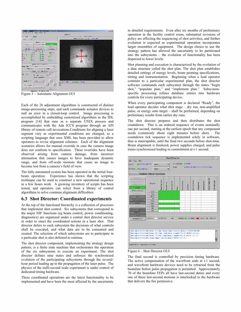
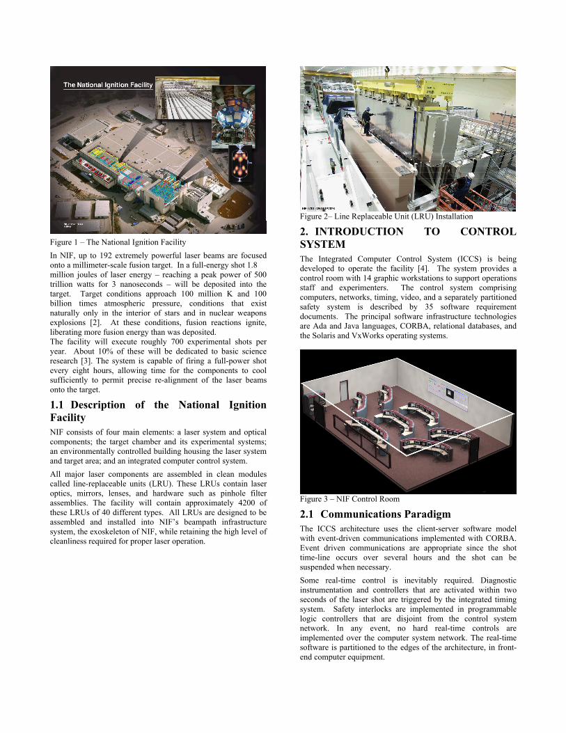
Figure 5 – Automatic Alignment GUI Each of the 26 adjustment algorithms is constructed of distinct image-processing steps, and each commands actuator devices to null an error in a closed-loop control. Image processing is accomplished by embedding customized algorithms in the IDL program [14] that runs as a separate UNIX process and communicates with the Ada ICCS program through an API library of remote call invocations.Conditions for aligning a laser segment vary as experimental conditions are changed, so a scripting language that uses XML has been provided to allow operators to revise alignment schemes. Each of the alignment scenarios allows for manual override in case the camera image does not conform to specification. These overrides have been observed arising from camera damage, from incorrect attenuation that causes images to have inadequate dynamic range, and from off-scale motions that cause an image to become lost from a camera’s field of view. The fully automated system has been operated in the initial four-beam operation. Experience has shown that the scripting technique can be used to construct a new operational sequence in a few hours work. A growing inventory of scripts has been tested, and operators can select from a library of control algorithms to solve common alignment difficulties.
6.3 Shot Director: Coordinated experiments At the top of the functional hierarchy is a collection of processes that implement shot control. Six subsystems that correspond to the major NIF functions (eg beam control, power conditioning, diagnostics) are organized under a central shot director service in order to enact the coordinated actions in a laser shot. That director defers to each subsystem the decisions of what controls shall be executed, and what data are to be consumed and created. The selection of which subsystems are to participate in a particular shot is also deferred to runtime. The shot director component, implementing the strategy design pattern, is a finite state machine that orchestrates the operation of the six subsystems to execute an experiment. The shot director defines nine states and enforces the synchronized evolution of the participating subsystems through the several-hour period leading up to the propagation of the laser pulse. The physics of the milli-second scale experiment is under control of dedicated timing hardware. These coordinated operations are the latest functionality to be implemented and have been the most affected by the uncertainty
in detailed requirements. Even after six months of preliminary operation in the facility control room, substantial revisions of policy are affecting the sequencing of shot activities, and further evolution is expected as experimental operation incorporates larger ensembles of equipment. The design choice to use the strategy pattern has allowed the uncertainty to be partitioned into the subsystems – the evolution of functionality has been dispersed to lower levels. Shot planning and execution is characterized by the evolution of a data structure called the shot plan. The shot plan establishes detailed settings of energy levels, beam pointing specifications, timing and instrumentation. Beginning when a lead operator commits to a particular experimental plan, the shot director software commands each subsystem through the states “begin shot,” “populate plan,” and “implement plan.” Subsystem-specific processing refines database entries into hardware controls for every participating device. When every participating component is declared “Ready”, the lead operator decides what shot stage – dry run, non-amplified pulse, or energy onto target – shall be performed, depending on preliminary results from earlier dry runs. The shot director prepares and then distributes the shot countdown. This is an ordered sequence of events nominally one per second, starting at the earliest epoch that any component needs (commonly about eight minutes before shot). The countdown tick sequence is implemented solely in software, thus is interruptible, until the final two seconds before shot-time. Beam alignment is finalized, power supplies charged, and pulse trains synchronized leading to commitment at t-1 second.
Figure 6 – Shot Director GUI The final second is controlled by precision timing hardware. The active compensation of the wavefront ends at t-1 second, and wavefront hardware devices need to be retracted from the beamline before pulse propagation is permitted. Approximately 70 of the beamline FEPs all have last-second duties and every one of these last-second motions is interlocked to the hardware that delivers the fire permissive.

If every safety and equipment interlock achieves its permissive state, the laser pulse is propagated and amplified. The beam reaches the target chamber about 1 millisecond after first being generated, and undergoes amplification of 15 orders of magnitude of energy from nano-Joules to Mega-Joules. Data from diagnostic instrumentation including shot-time images are collected for the control system to acquire, analyze and archive. The shot director software automatically transitions its state through “post countdown,” and “analyze shot,” providing experimentalists with their raw data. This cycle of countdown and analyze is repeated as needed through dry-runs and non-amplified shots until a single target shot achieves the experiment goals. After the entire experiment sequence completes, the shot director declares “end shot cycle” and all subsystems return to decentralized activities until another shot is planned. As of November 2002, about 35 complete shots have been performed, with participation from every subsystem except the target experimental chamber. High power amplification is not scheduled until early 2003, but power equipment has discharged energy into dummy loads.
7. EXPERIENCE WITH DISTRIBUTED SYSTEM A distributed system that runs processes on hundreds of computers has failure modes that challenge the developers in different ways from traditional designs. Fifty of the intended 300 FEPs have already been installed, as have some 60 supervisory processes. This large and growing number of distributed interfaces allows possibly non-deterministic messaging behavior. CORBA objects in the ICCS architecture are typically long lived. They come into existence when a process is started and remain until the process is terminated. Where there is dynamic object creation and removal, their number is small in comparison to the existing steady state CORBA objects. The ICCS paradigm of thousands of CORBA server objects that communicate across TCP-IP is effective only to the degree that services provide for predictable communications and effective recovery practices. Debugging distributed systems is difficult at best. The potential for deadlock is present in this open communication environment. Deadlocks are programming errors that must be found and corrected. Stringent testing can expose many deadlocks, but additional ones will likely arise in production operation. In a distributed system, deadlocks can produce a cascading effect that becomes very hard to diagnose. This is because a deadlock in one process causes another process to block, which in turn causes another process to block, etc. Many times it is even difficult to identify all of the affected programs. In addition to deadlock potential, highly distributed systems deal with connection management. In broad terms two kinds of communication failures arise. Connection timeouts are caused by slow or overloaded networks and by slow programs. Connection breakdowns occur when computers or networks fail or when processes fail due to unhandled exceptions. The challenge is to provide client notification of server state changes while maintaining location transparency in the application software.
Experience has proved that it is not realistic to expect every one of the application classes to incorporate effective exception handling for each mode of communication failure. Therefore the ICCS Framework contains connection abstractions that manage the health of each CORBA reference. Calls are timed so that longer-than-expected response times raise exceptions in the caller (and the service is abandoned). The validity of CORBA references is centrally maintained and replacement references are provided transparently to the clients. The ICCS system manager framework maintains rudimentary process state information from heartbeats. The framework provides notification to subscribers of publisher failures and initiates automatic subscriber reconnection when a publisher service is restarted. Attempted recovery from a communication failure follows the same pattern everywhere. Ada packages are automatically generated from IDL interface specifications. These packages are enhanced (by processing the generated sources) with exception handlers to handle several classes of communication breakdowns. By burying the recovery attempt in the connection management layer the same behavior is assured across the system. Using these tactics, the connection management framework provides error detection, notification and recovery inside the CORBA communication infrastructure. The applications are left to respond to the implications of the failure – to figure out what to do when the desired service is unavailable – without the concern of diagnosis and maintenance of connections.
8. PROCESS MANAGEMENT RESULTS The Software Change Control Board (SCCB), composed of line managers and QA staff, makes the decisions about timing and content of incremental releases. This board responds to project needs for functionality and tracks reports from test incidents. The principal tool used to manage product evolution is the Software Change Request (SCR). Every reported defect gives rise to an SCR when it is diagnosed, as do newly revealed requirements. Management observes the rate of satisfaction of SCRs and measures the growth of the installed base of software measured by source lines of code (SLOC). The ICCS presently contains some 612 KSLOC’s of delivered code. 63% of the code inventory is in Ada, 26% is in Java and the balance is divided between C, HTML and shell scripts. The measurement protocols exclude significant parts of the software inventory, which totals approximately 2.0 million SLOCS. The exclusions arise from redundant materials (for example units in the inventory of multiple operating systems), code that was automatically generated by translation tools (such as CORBA server skeletons), and COTS products. Some of the code entering the inventory has been inspected by teammates of the original developer. The intention is to inspect a significant fraction of the product as effort allows. To date, some 20 KSLOCs have been inspected, at a cost of 200 worker-hours (20 different reviewers have contributed). This process has identified some 600 problems – 100 of which were identified as “major” with potential to cause a software defect. All the significant issues from inspection have been tracked to closure through the SCR process.

8.1 Testing Product testing is the major technique for assessing and improving quality. The ICCS organization includes a 13-person test team. The formal test of each incremental release is performed in three phases and test incidents from all three are adjudicated by the SCCB. Offline tests are performed in a dedicated facility. This test phase finds coding errors, interface mismatches, missing requirements, and standards adherence issues. The test facility has a limited inventory of control hardware and emulator devices so some controls interface issues are exposed as well.
Test integration into a laser laboratory is possible for most subsystems. In this test context the testers can diagnose more hardware interface errors, incorrect requirements, and remanent coding and standards defects. After qualification in the laboratory, including error patching under SCCB control, the ICCS release is deployed into the NIF control room to support the test of the laser itself. Because of the size and complexity of the facility, no provision has been made for manual control of coordinated laser operation. Only through the ICCS can laser pulses be propagated. Therefore the ICCS delivery into the control room is a project-wide milestone.
The performance of the ICCS software is observed by measures on the defect rate reported in SCRs. To date some 3200 defect reports have been filed. Since control room operation started, the rate has been at its highest, exceeding 300 per month (385 SCRs were filed in October 2002, the last month for which data are available). The high rate is attributable mostly to the intense scrutiny due to multiple test cases, and to the first-ever integration of all subsystems in a hardware test that fires experimental shots. (There is a minor effect of SCCB policy that may inflate the defect report rate. When urgent changes are needed to support test operation, multiple fine-grained SCRs are sometimes filed to facilitate tracking. In less demanding times, the same defect might have been managed by a single request.)
Figure 7 – Offline Test Facility There are presently some 550 open defects; 20 to 30% of these are urgent defects that represent failures to complete a test. Recently the average defect has taken 108 days to close (urgent defects close in 60 days, on average). More than 90% of repairs are successful at the first retest. The organization is aware that the rate of defect reporting is increasing, and interprets this as a sign that the product is immature. At the same time, test operations are proceeding in support of the project’s goals. Shots are being performed, and the control system is supporting progress toward a 4-beam shot at full amplification that will achieve 10 KJoule in the target, albeit through the careful attention of our highly capable staff. Management anticipates that the defect rate will decrease in due time, and that the system will succeed as the scale of operation
increases. Confidence is high and the entire organization is proud of their accomplishment in this exceptionally difficult task.
9. ACKNOWLEDGEMENTS The control system is the product of a team of some 55 highly professional software developers who are collaborating with the 13-member test team. David Mathisen, Karl Wilhelmsen and Lewis Van Atta lead the particular parts of the system highlighted in this paper.
10. REFERENCES [1] E. Moses et al., “The National Ignition Facility:
Status and Plans for Laser Fusion and High-Energy-Density Experimental Studies,” Eighth International Conference on Accelerator and Large Experimental Physics Control Systems (ICALEPCS 2001), San Jose, CA, Nov. 2001. The Proceedings of ICALEPCS 2001 are available at http://www.slac.stanford.edu/econf/C011127/proceedings.html.
[2] E. Michael Campbell, Neil C. Holmes, Steve B. Libby, Bruce A. Remington, and Edward Teller “The Evolution of High-Energy-Density Physics: from Nuclear Testing to the Superlasers” Laser and Particle Beams 1997, vol. 15, no. 4, pp 607-626.
[3] Keay Davidson “From Swords to Supernovae” Sky and Telescope, November 1997, p 36.
[4] L. J. Lagin et al., “The Overview of the National Ignition Facility Distributed Computer Control System,” ICALEPCS 2001.
[5] John P. Woodruff et al., “Quality Control, Testing and Deployment Results in NIF ICCS,” ICALEPCS 2001.
[6] John P Woodruff and Paul VanArsdall, "A Large Distributed Control System Using Ada in Fusion Research," SigAda 1998.
[7] R. Carey, et al., “Large-scale CORBA-distributed Software Framework for NIF Controls,” ICALEPCS 2001.
[8] Kirby W. Fong et al., “Application Software Structures Enable NIF Operations,” ICALEPCS 2001.

[9] Lewis Van Atta et al., “The Wavefront Control System for the NIF,” ICALEPCS 2001.
[10] R. Zacharias et al., “The National Ignition Facility Wavefront Control System,” Third International Conference on Solid State Lasers for Application to Inertial Confinement Fusion, Monterey, CA, June 1998.
[11] J.T Salmon, et al., “Active and Adaptive Optical Systems,” (SPIE - International Society for Optical Engineering, Bellingham, WA, 1991:Proc. SPIE 1452) pp.459-467.
[12] “Lick Observatory Laser Guide Star Adaptive Optics System Commissioning,” http://www.llnl.gov/urp/science/lgs_www/lgs_lick.html
[13] Chris Haynam et al., “Computational Modeling in Support of NIF Operations,” ICALEPCS 2001.
[14] IDL, Research Systems, Inc. (Boulder, CO). http://www.rsinc.com
This work was performed under the auspices of the U.S. Department of Energy by the University of California, Lawrence Livermore National Laboratory under Contract No. W-7405-Eng-48.