Embed Size (px)
Citation preview

NASA
N rr) m P n z + 4 m 4 z
TECHNICAL NOTE D-4352
METHOD FOR CALCULATING ALLOWABLE CREEP STRESS IN LINEARLY INCREASING STRESS ENVIRONMENT
I 1 '
by Charles L. Whitmarsh, Jr. Lewis Research Center Cleueland, Ohio
NATIONAL AERONAUTICS A N D SPACE A D M I N I S T R A T I O N WASHINGTON, D. C. J A N U A R Y 1968
https://ntrs.nasa.gov/search.jsp?R=19680017292 2018-05-28T21:43:17+00:00Z

u-dcs' ERRATA
NASA Technical Note D-4352
- .' Y
METHOD FOR CALCULATING ALLOWABLE CREEP STRESS
IN LINEARLY INCREASING STRESS ENVIRONMENT
By Charles L. Whitmarsh, Jr.
January 1968
Page 5: Equation (IO) should read
Page 6, figure 1: The values of the slope of the Larson-Miller correlation should be -1.9X10- , -1.8, -1. 3, - 1 . 2 , and -1. I. 4
.-
NASA-Langley, 1968 Issued 5-21-68
TECH LIBRARY KAFB, NM
METHOD FOR CALCULATING ALLOWABLE C R E E P STRESS
IN LINEARLY INCREASING STRESS ENVIRONMENT
By C h a r l e s L. Whi tmarsh , Jr.
Lewis R e s e a r c h C e n t e r Cleveland, Ohio
NATIONAL AERONAUT ICs AND SPACE ADM I N I STRATI ON
For sale by the Clearinghouse for Federal Scientific and Technical Information Springfield, Virginia 22151 - CFSTI price $3.00

METHOD FOR CALCULATING ALLOWABLE CREEP STRESS
IN LINEARLY INCREASING STRESS ENVIRONMENT
by Charles L. Whitmarsh, Jr.
Lewis Research Center
SUMMARY
An analytical technique was developed to calculate the allowable design stress for a specified creep limit of a material under conditions of linear s t ress buildup and constant temperature. The analysis utilizes constant-stress creep data in the integration of a s t ress -dependent creep rate over the material history. Allowable design s t ress limits for 1'-percent creep of refractory metals in the temperature range 800' to 1600' K a r e increased by 25 to 57 percent when compared with calculations based on the constant end- of -life s t ress condition.
INTRODUCTION
An accurate assessment of the allowable s t resses that cause high-temperature creep in materials is important for space power systems currently under study. A great body of experimental creep data has been obtained for materials of interest under conditions of constant stress and temperature. The Larson-Miller (ref. 1) correlation, for example, which plots allowable constant stress against a combined time and temperature parameter for a fixed value of creep, is widely used for interpolation among the data. However, con- ditions of variable stress and/or temperature may be encountered in practice, and few creep data for such conditions exist. The situation that prompted the present work was the calculation of cladding thickness for a cylindrical nuclear -reactor fuel element de- signed to contain fission gases being generated at a constant rate. Internal pressure and, therefore, s t resses are not constant (although temperature can be reasonably assumed to be), but increase linearly from some initial low value. Assuming that the end-of-life stress is constant over the entire reactor lifetime is unduly conservative, and the calcu- lational results of cladding thicknesses and core volumes are greater than necessary.

This assumption may severely penalize high -temperature -reactor concepts intended for space power.
If the creep rate of a material under stress is assumed to be independent of prior creep sustained at other conditions, then total creep can be accumulated. This idea is not new (ref. 2) and has been experimentally verified for several materials (refs. 3 to 5). Recently, this technique has been used for the design of radioisotope capsules where helium, a decay product, builds up internal pressure (ref. 6).
for variable-stress situations and to use as the basis for the analysis experimental data obtained under constant -stress conditions.
The purpose of this analysis is to apply the concept of accumulation of total creep
ANALY S I S
General Case
The basic assumption used in the following analysis is that the creep rate of a mate- rial under s t ress is independent of prior creep sustained at other conditions and that total creep, therefore, can be accumulated, according to the relation
lEf de = JTf ;(U, T)dT
where E is the creep of a sample; i ( o , T) is the creep rate of a sample and is in general a function of the stress u and the temperature T to which the sample is subjected; and cf and T~ represent the final fractional elongation and final time, respectively.
If the creep rate is now assumed to be constant for the time period of an experiment at constant stress and temperature (second-stage creep only), then the creep rate be written as the ratio of some fractional elongation to the time tO(u, T) over which this elongation occurred. Thus
can
To facilitate the translation of these data to other values of E and t, the time tf(u, T) required for the design creep Ef to occur can be defined as
2

I
where the subscript f is used to differentiate between design conditions and the experi- mental test conditions in equation (2). Substitution of this relation into equation (1) and integrating the left side yield
To carry out the integration, tf(u7 T) is written as an explicit function of stress and tem- perature. A useful relation to accomplish this is the Larson-Miller (ref. 1) correlation. Under those conditions where the Larson-Miller correlation can be represented by a straight line on a semilog graph, it can be written as
log u = m P + log a = mT(K + log to) + log a (5)
where
m slope of equation
P Larson-Miller parameter
a ordinate u intercept
T absolute temperature
K constant dependent on material
to time of exposure
Rearranging equation (5) into an explicit relation of time to yields
and combining equations (2), (3), (4), and (6) yields
3
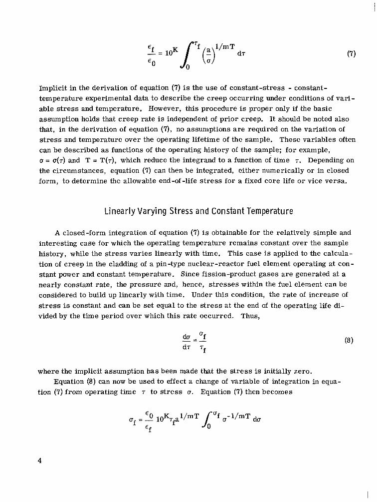
Implicit in the derivation of equation (7) is the use of constant-stress - constant- temperature experimental data to describe the creep occurring under conditions of vari- able stress and temperature. However, this procedure is proper only if the basic assumption holds that creep rate is independent of prior creep. It should be noted also that, in the derivation of equation (7), no assumptions a r e required on the variation of stress and temperature over the operating lifetime of the sample. These variables often can be described as functions of the operating history of the sample; for example, (T = U(T) and T = T(T), which reduce the integrand to a function of time T. Depending on the circumstances, equation (7) can then be integrated, either numerically or in closed form, to determine the allowable end-of-life stress for a fixed core life or vice versa.
Linearly Varying Stress and Constant Temperature
A closed-form integration of equation (7) is obtainable for the relatively simple and interesting case for which the operating temperature remains constant over the sample history, while the stress varies linearly with time. This case is applied to the calcula- tion of creep in the cladding of a pin-type nuclear-reactor fuel element operating at con- stant power and constant temperature. Since fission-product gases a re generated at a nearly constant rate, the pressure and, hence, s t resses within the fuel element can be considered to build up linearly with time. Under this condition, the rate of increase of stress is constant and can be set equal to the stress at the end of the operating life di- vided by the time period over which this rate occurred. Thus,
du - 'f - - -
where the implicit assumption has been made that the stress is initially zero.
tion (7) from operating time T to s t ress 0. Equation (7) then becomes Equation (8) can now be used to effect a change of variable of integration in equa-
€ 0 K l/mT Uf = - 10 7 fa €f
4

Integration yields
m T At this point, examination of equation (6) reveals that the quantity a ( l O K ~ f ) is equal to the stress value predicted by the Larson-Miller correlation for the condition This point is denoted as aLM and a stress modifying factor
= cf. is defined as
f -4-1/mT Thus, equation (9) becomes
and states that, when the stress is linearly increasing and the temperature is constant over the operating history, the allowable end-of-life stress of to achieve a desired creep value is equal to the product of the s t ress oLM (obtained from the Larson-Miller correlation for an equivalent value of creep) and a factor + that depends on the material and the operating temperature.
terest and is shown plotted as a function of temperature in figure 1. Data for these ma- terials were taken from references 7 and 8 and were assumed to have a constant Larson- Miller slope over the temperature range plotted. For the temperature range 800' to 1600' K, the least sensitivity is exhibited by NAS-36 with + values of 1.25 to 1.4, re- spectively, and the greatest sensitivity is exhibited by FS-85 with + values of 1.37 to 1.57, respectively. From figure 1 it can be seen that + increases with operating tem- perature and is nearly linear over a broad range.
To illustrate the use of the + factor, imagine a hypothetical application requiring 10 000 hours' service at a constant temperature of 2200' F (1480' K) for which the stress on the sample is linearly increasing. If 1-percent creep and the material T-111 a r e specified, for example,. use of the Larson-Miller data given in reference 7 indicates a design stress limit aLM of about 5000 psi (0.18 MN/m2). From figure 1, + for T-111 at 2200' F (1480' K) is about 1.42. Hence, a stress of of about 7100 psi (0.26 MN/m2) at the end of life could be allowed.
The + factor was evaluated for several high-temperature refractory alloys of in-
5
li.

I
1.55
1. 50
3
s ~ 1.45
f-l
of w m
1.40 2
1.35
1. 30
1 7.54
1.60}
-
-
-
-
I
-
.-
e
Material Composition Slope of Larson- Miller correlation,
OK- 1
/ T-lll / /
-LL, - l -.. 1 . -2- __ I _. --
Cb-28Ta-10.5w-O.9Zr W-25Re
Ta-W-2Hf
Cb-1Zr
Ta-5.7W-1.56Re- 0.7Mo-0.25Hf-0.13Zr- 0.015C-0.015N
- 5 . 9 x 1 0 - ~ -5. 8
-3.9
-3. 8
-3.4
Temperature, OF
I . I 1 I I .-I -~ I I I I
800 900 1000 1100 1200 1300 1400 1500 1600 1700 Temperature, OK
Figure 1. - Calculational factor to increase allowable design s t r e s s for 1-percent c reep in several refractory-metal alloys.
Application to Reactor-Fuel-C lad Design
In a study of a small, fast, gas-cooled, high-temperature reactor employing pin- type fuel elements, the cladding thickness was calculated for the constant stress aLM as well as fo r the linearly varying stress. The allowable design stress and the pressure on the fuel cladding were related by means of the tangential stress equation for thick wal l cylinders (ref. 9) evaluated at the inside surface of the tube wall
(ri + r;)Pi - 2rOpo 2 a =
(rz - r:)
6

0 I I
where r is the tube radius, P is the pressure, and the subscripts i and o refer to inside and outside conditions, respectively. Equation (11) was used to evaluate the allowable stress from which the cladding thickness was determined by equation (12). The cladding material was tungsten - 25 percent rhenium, and the operating conditions were 25 000 hours at 1800’ K with 1 percent creep. conditions, with a 60-percent increase allowed in design stress over the constant-stress assumption. A saving in cladding thickness was effected, which allowed an increased fuel loading that resulted in a core volume reduction of 18 percent with the use of the technique reported herein as compared with that of the constant-stress assumption.
tions. a constant pressure on the outside of the element, the cladding is initially in compression. As the fission gases build up throughout the reactor life, this compression decreases and changes to tension when the fission-gas pressure exceeds the coolant pressure. end of life, the net pressure on the cladding equals the fission-gas pressure minus the coolant pressure. dashed line shows the fission-gas pressure alone, and the lower dashed line shows the net pressure (fission gas minus coolant) on the cladding. The solid line starting at zero
EE r
The factor + was 1.6 under these
? The foregoing analysis utilized the following approximation to actual reactor condi -
Because the initial fission-gas pressure was zero and the gaseous coolant exerts ?
A t the
These pressure histories a re presented in figure 2. The upper
I
I
0
Fission gas pressure at end of life, P 7 fg ‘\I
Tf Time
Figure 2. - Pressure history of a nuclear reactor fuel element with respect to containment of fission gases.
7

and ending at the end-of-life net pressure Pf was the assumed pressure history used for the stress calculations. This assumption is considered conservative, since the assumed tensile s t ress was always equal to or greater than the actual.
DlSCU S S ION
The analytical method presented herein appears mathematically suitable for any total creep limit within the constant-creep-rate assumption and is not restricted to the c
creep limit of the experimental test data. should be limited to low creep limits. Also, uncertainties exist in the use of the Larson- Miller creep rate correlation where longtime test data for materials of interest a r e usually nonexistent, and thus extended extrapolations a r e required. Fortunately, the stress-increase factor I$ plotted in figure 1 is relatively insensitive to changes in both the value of the slope of the Larson-Miller correlation and the temperature. For exam- ple, a 100-percent increase in either m o r T causes the factor to increase about 15 per cent.
be used if a closed analytical solution were not required. Thus, equation (4) could be solved numerically by use of a digital computer if sufficient test data and/or problem history data were available.
which the fuel cladding thickness is determined by creep as opposed to those situations in which limitations are related to material elastic properties or strength. In general, this application will include high-power-density - high-temperature systems that are required to retain fission gases in the core. Of course, fission gas pressure is only one of the factors upon which cladding thickness depends, and in a detailed reactor design, additional items, such as thermal cycling, heat-transfer effects, and fabrication, must be considered.
To assure such application, however, its use
I
In theory, any stress-temperature- creep correlation and/or any stress history could
Method application to nuclear-reactor design is restricted to those situations in
S U M M A R Y OF RESULTS
An analytical method was developed to calculate allowable end-of-life stress for a design creep limit of a material under conditions of linearly increasing stress and con- stant temperature. For a given material and creep limit, a temperature dependent fac- tor was calculated which represents the ratio of the allowable end-of-life stress to the constant stress obtained from Larson-Miller data.
Calculations were performed to show that the allowable end-of-life s t ress for
8

- . . . . . . ... .. ,
i i
i
refractory metals, and a temperature
1 i
, t
!
for the conditions of l-percent creep, and linearly increasing stress, range of 800' to 1600' K, was increased by 25 to 57 percent when
compared with constant-stress calculations. Also, the core volume of a small, fast-spectrum, high-temperature, gas- cooled
reactor was reduced by 18 percent when the method presented herein was used for the determination of the required fuel cladding thickness.
Lewis Research Center, National A e r onauti cs and Space Administration,
Cleveland, Ohio, November 7, 1967, 120-27-06-05-22.
1. I I 4 P
2.
3.
4.
5.
6. I I
7.
8.
9.
REFERENCES
Larson, F. R. ; and Miller, James: A Time-Temperature Relationship for Rupture and Creep Stresses. Trans. ASME, vol. 74, no. 5, July 1952, pp. 765-771; Disc., pp. 771-775.
Robinson, Ernest L. : Effect of Temperature Variation on the Long-Time Rupture Strength of Steels. Trans. ASME, vol. 74, no. 5, July 1952, pp. 777-781.
Serensen, S. V. ; and Strelaiev, V. S. : Creep Resistance and Low-Cycle Fatigue of Fiberglass Plastics. Joint International Conference on Creep. Institute of Mechan- ical Engineers, 1963, pp. 3-93 to 3-98.
McCoy, H. E. : Creep-Rupture Properties Under Conditions of Constant and Varying Stresses. Nucl. Applications, vol. 2 , no. 6, Dec. 1966, pp. 481-485.
Kennedy, Alfred J. : Processes of Creep and Fatigue in Metals. John Wiley and Sons, Inc., 1963, pp. 401-428.
Nichols, J. P. ; and Winkler, D. R. : A Program for Calculating Optimum Dimensions of Alpha Radioisotope Capsules Exposed to Varying Stress and Temperature. Rep. No. ORNL -TM-1735 (NASA CR-72172), Oak Ridge National Lab., Apr. 1967.
Moss, Thomas A. : Materials Technology Presently Available for Advanced Rankine Systems. Nucl. Applications, vol. 3, no. 2, Feb. 1967, pp. 71-81.
Sawyer, J. C. ; and Steigerwald, E. A. : Generation of Long Time Creep Data on Refractory Alloys at Elevated Temperatures. TRW Equipment Labs. (NASA CR-72185), Jan. 17, 1967.
Singer, Ferdinand L. : Strength of Materials. Harper and Brothers, 1951.
NASA-Langley, 1968 - 22 E-4188 9

"The aeronautical and space activities of the United States shall be conducted so as to contribute . . . to the expansion of human knowl- edge of phenomena in the atmosphere and space. The Admillistration shall provide for the widest practicable and appropriate dissemination of information concerning its activities and the results thereof."
-NATIONAL AERONAUTICS AND SPACE ACT OF 1958
NASA SCIENTIFIC AND TECHNICAL PUBLICATIONS
TECHNICAL REPORTS: Scientific and technical information considered important, complete, and a lasting contribution to existing knowledge.
TECHNICAL NOTES: Information less broad in scope but nevertheless of importance as a contribution to existing knowledge.
TECHNICAL MEMORANDUMS: Information receiving limited distribu- tion because of preliminary data, security classification, or other reasons.
CONTRACTOR REPORTS: Scientific and technical information generated under a NASA contract or grant and considered an important contribution to existing knowledge.
TECHNICAL TRANSLATIONS: Information published in a foreign language considered to merit NASA distribution in English.
SPECIAL PUBLICATIONS: Information derived from or of value to NASA activities. Publications include conference proceedings, monographs, data compilations, handbooks, sourcebooks, and special bibliographies.
TECHNOLOGY UTILIZATION PUBLICATIONS: Information on tech- nology used by NASA that may be of particular interest in commercial and other non-aerospace applications. Publications include Tech Briefs, Technology Utilization Reports and Notes, and Technology Surveys.
1
I Details on the availability of these publications may be obtained from:
SCIENTIFIC AND TECHNICAL INFORMATION DIVISION
NATIONAL AERONAUTICS AND SPACE ADMINISTRATION
Washington, D.C. PO546