Embed Size (px)
Citation preview
NASA Perspectives on Airframe Structural Substantiation: Past Support
and Future Developments
Richard YoungNASA Langley Research Center
Hampton, Virginia
FAA/EASA/Industry Composite Damage Tolerance
and Maintenance Workshop, Tokyo
June 4-5, 2009
Outline of Briefing
• History of NASA Composite Structures Programs
• Applications in Commercial Aircraft
• NASA Aircraft Energy Efficiency Program (1972-1986)
• NASA Advanced Composites Program (1989-2000)
• Applications in Space Transportation Vehicles
• NASA Space Shuttle (1974 – present)
• New space launch vehicles (1996 – present)
• Progress in Composites Damage Mechanics Research….Past, present, and future
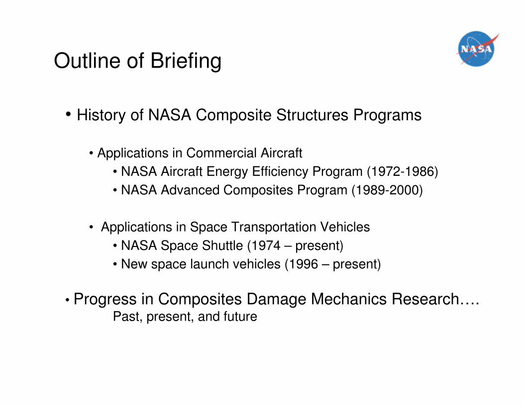
Aircraft Energy Efficiency (ACEE) Program(1972-1986)
Program Goals:• Obtain actual flight experience • Obtain environmental exposure data
Boeing 737 composite
horizontal stabilizer
Douglas DC-10 composite
Rudder and vertical stabilizer
Boeing 727 composite
elevator
Lockheed L-1011
composite aileron
350 Composite components accumulated over 3.5 million flight hours by 1993!
350 Composite components accumulated over 3.5 million flight hours by 1993!
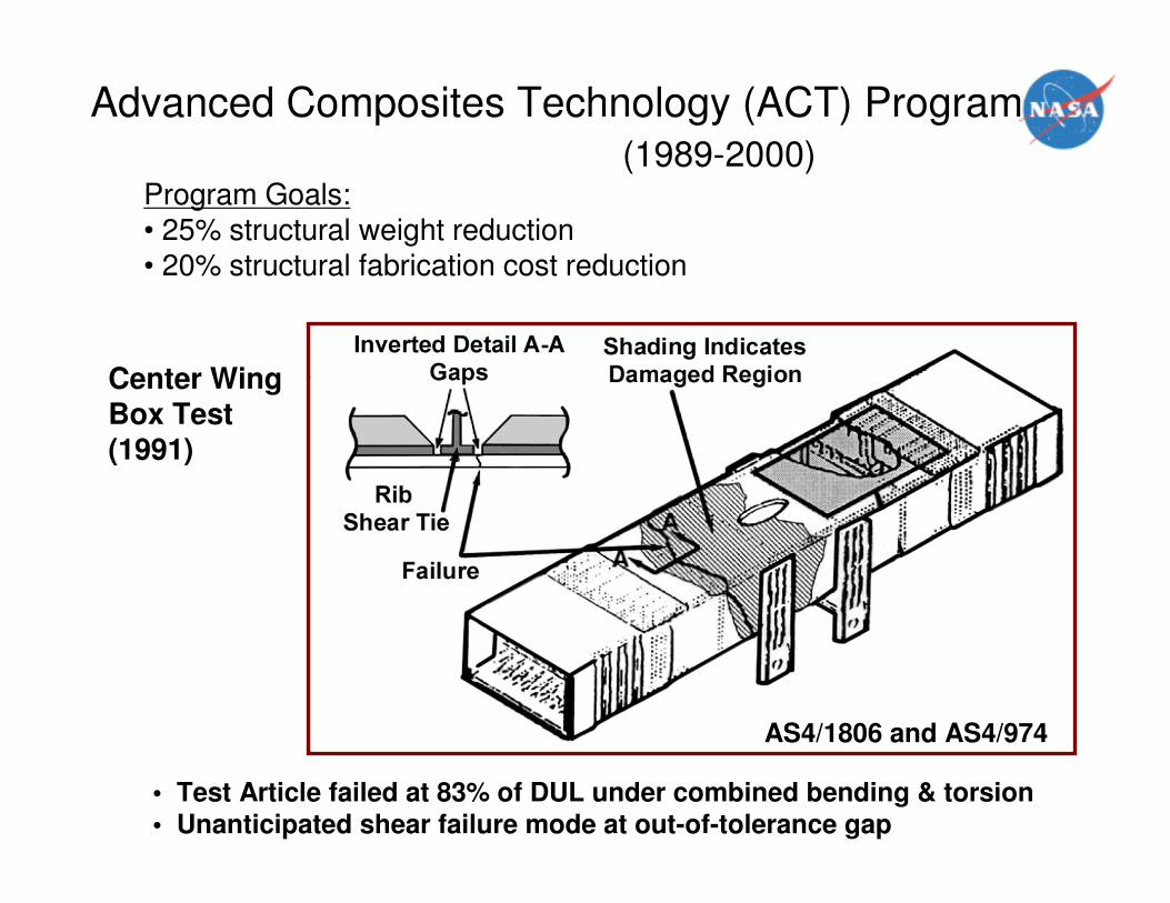
Advanced Composites Technology (ACT) Program
(1989-2000)Program Goals:• 25% structural weight reduction• 20% structural fabrication cost reduction
Center Wing Box Test (1991)
• Test Article failed at 83% of DUL under combined bending & torsion• Unanticipated shear failure mode at out-of-tolerance gap
AS4/1806 and AS4/974
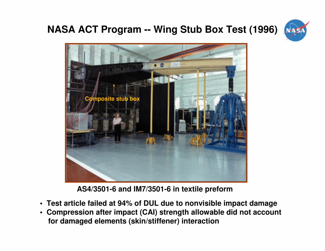
NASA ACT Program -- Wing Stub Box Test (1996)
Composite stub box
• Test article failed at 94% of DUL due to nonvisible impact damage
• Compression after impact (CAI) strength allowable did not accountfor damaged elements (skin/stiffener) interaction
AS4/3501-6 and IM7/3501-6 in textile preform
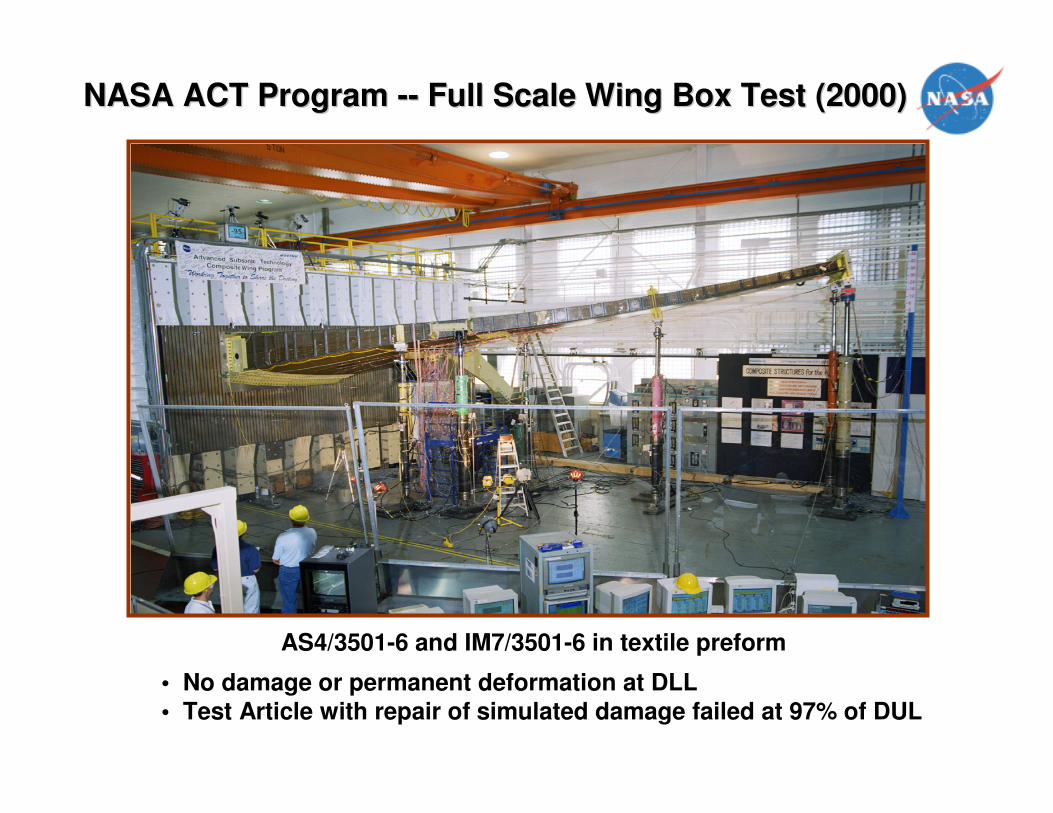
NASA ACT Program NASA ACT Program ---- Full Scale Wing Box Test (2000)Full Scale Wing Box Test (2000)
• No damage or permanent deformation at DLL
• Test Article with repair of simulated damage failed at 97% of DUL
AS4/3501-6 and IM7/3501-6 in textile preform
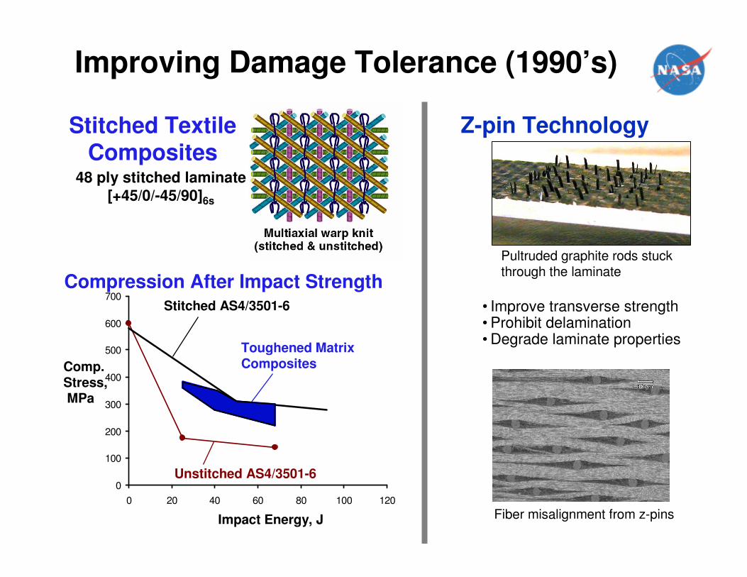
Stitched Textile Composites
48 ply stitched laminate
[+45/0/-45/90]6s
0
100
200
300
400
500
600
700
0 20 40 60 80 100 120
Unstitched AS4/3501-6
Stitched AS4/3501-6
Toughened MatrixCompositesComp.
Stress,MPa
Impact Energy, J
Compression After Impact Strength
Z-pin Technology
Pultruded graphite rods stuck through the laminate
Fiber misalignment from z-pins
• Improve transverse strength• Prohibit delamination• Degrade laminate properties
Improving Damage Tolerance (1990’s)
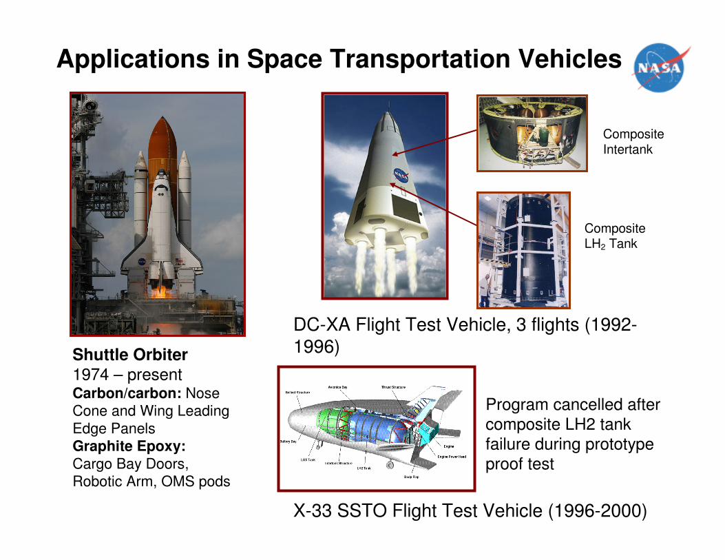
Applications in Space Transportation Vehicles
Shuttle Orbiter
1974 – presentCarbon/carbon: Nose
Cone and Wing Leading
Edge Panels
Graphite Epoxy:
Cargo Bay Doors,
Robotic Arm, OMS pods
DC-XA Flight Test Vehicle, 3 flights (1992-1996)
Composite Intertank
Composite LH2 Tank
X-33 SSTO Flight Test Vehicle (1996-2000)
Program cancelled after
composite LH2 tank failure during prototype proof test
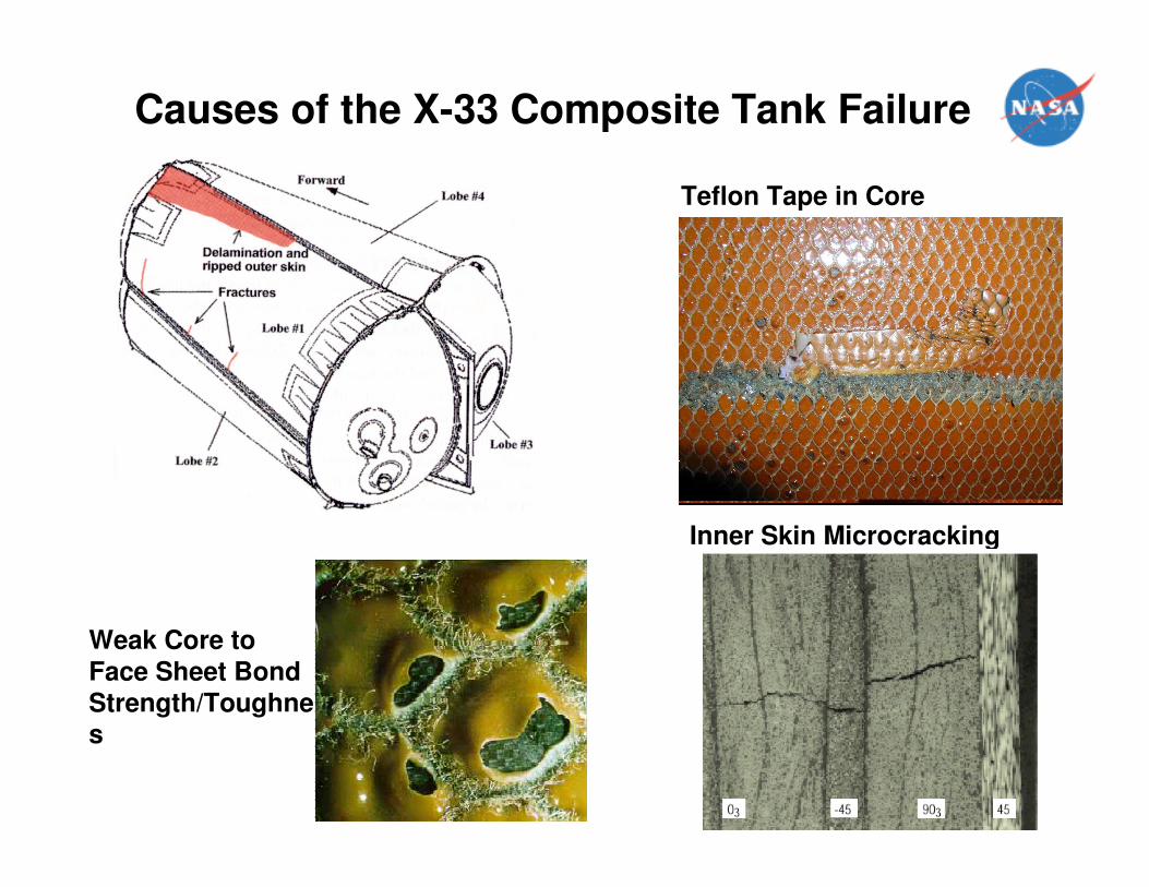
Teflon Tape in Core
Inner Skin Microcracking
Weak Core to
Face Sheet Bond Strength/Toughness
Causes of the X-33 Composite Tank Failure
Progress in Composite Damage Mechanics
• Building Block Approach
• Progressive damage analysis for through-thickness notches
• Delamination growth
• Sandwich Structure
• Textiles
• Damage Tolerant Concepts
• Composites Damage Science
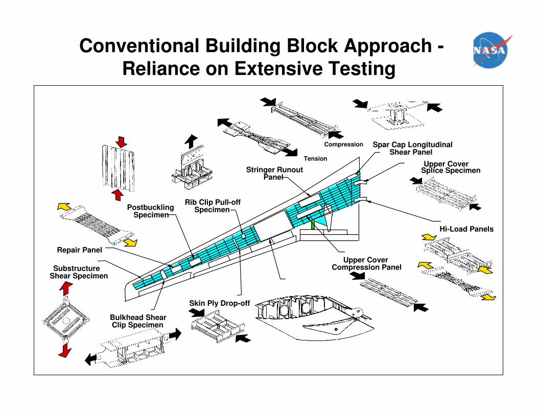
Upper Cover Compression Panel
Stringer Runout Panel
Tension
Skin Ply Drop-off
Bulkhead Shear Clip Specimen
Compression
Upper Cover Splice Specimen
Rib Clip Pull-off SpecimenPostbuckling
Specimen
Hi-Load Panels
Spar Cap Longitudinal Shear Panel
Repair Panel
Substructure Shear Specimen
Conventional Building Block Approach -
Reliance on Extensive Testing
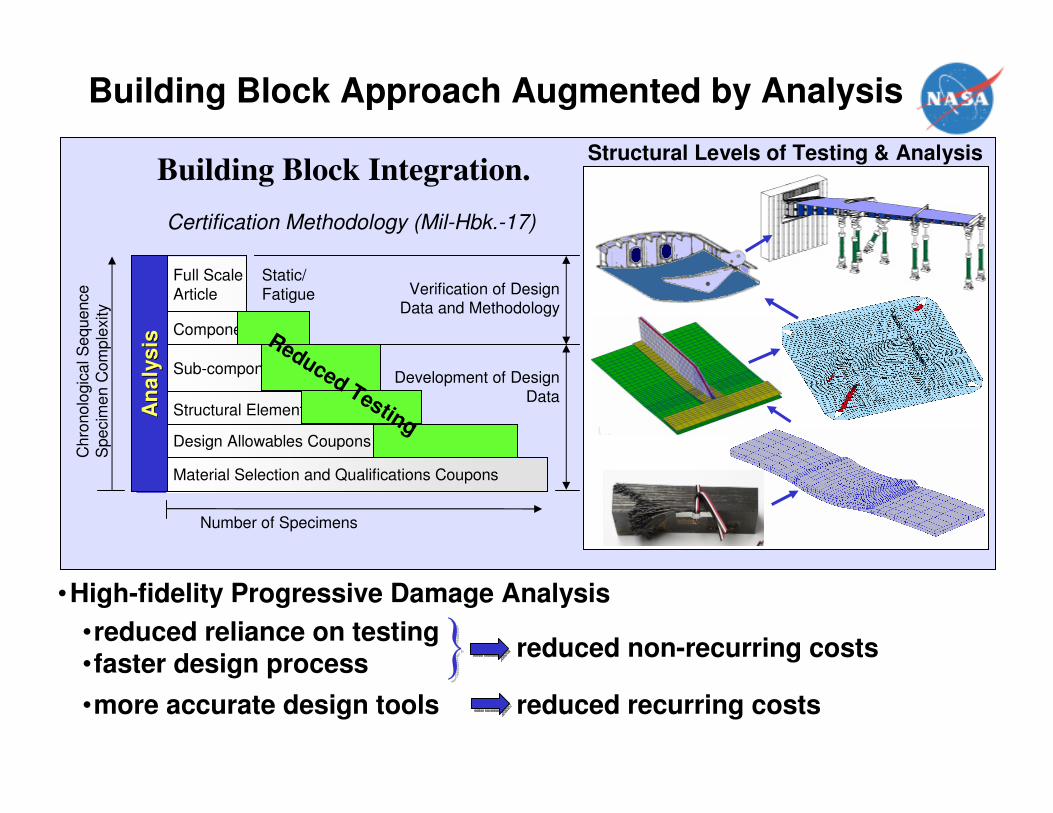
Building Block Integration.
Verification of Design Data and Methodology
Development of Design Data
Number of Specimens
Ch
rono
logic
al S
equence
Spe
cim
en
Com
ple
xity
Certification Methodology (Mil-Hbk.-17)
Structural Levels of Testing & Analysis
Static/Fatigue
Material Selection and Qualifications Coupons
Design Allowables Coupons
Structural Elements
Sub-components
Components
Full Scale
Article
•more accurate design tools reduced recurring costs
•reduced reliance on testing•faster design process
reduced non-recurring costs
An
aly
sis
An
aly
sis Reduced Testing
•High-fidelity Progressive Damage Analysis
Building Block Approach Augmented by Analysis
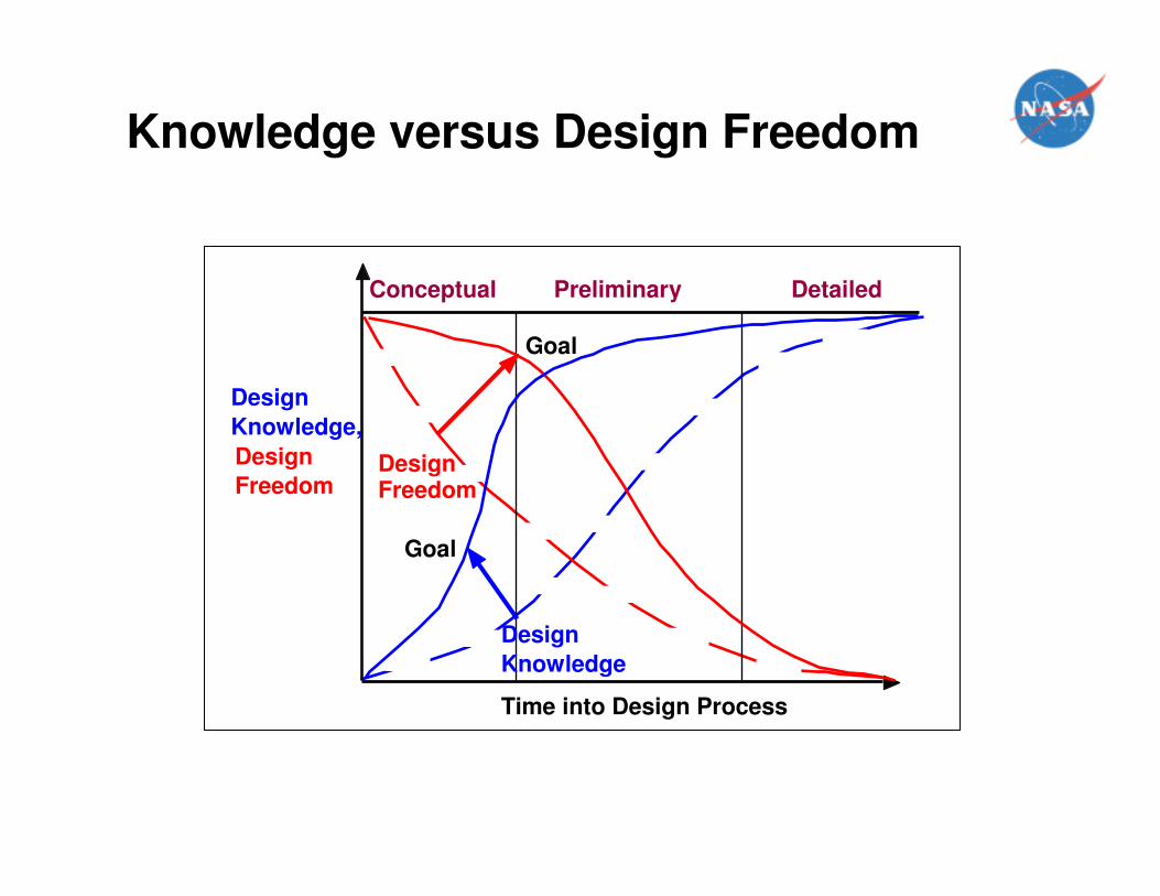
Conceptual Preliminary Detailed
Design
Knowledge,
Design
Freedom
Time into Design Process
DesignFreedom
Goal
Goal
Knowledge versus Design Freedom
Design
Knowledge
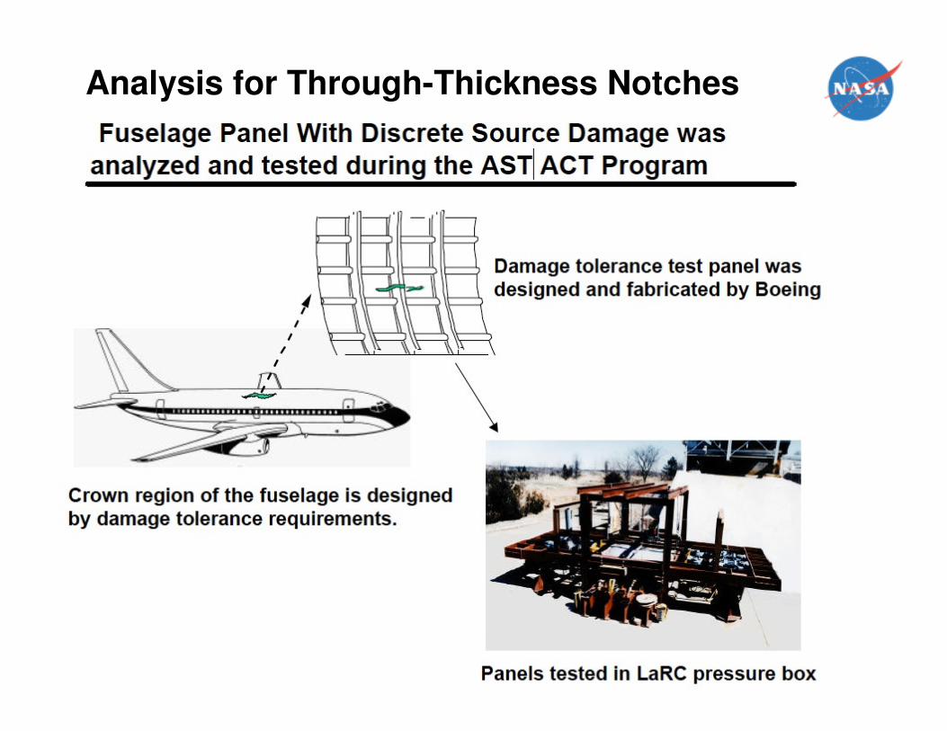
Analysis for Through-Thickness Notches
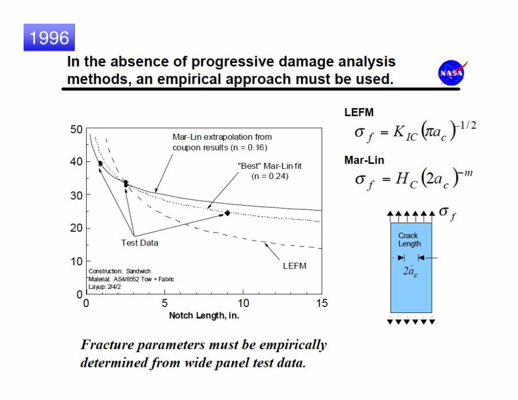
19961996
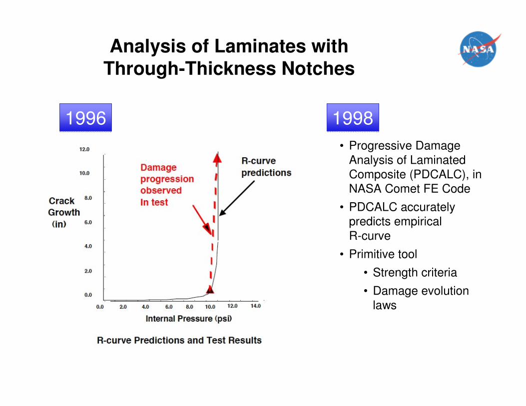
Analysis of Laminates with
Through-Thickness Notches
19961996 19981998
• Progressive Damage
Analysis of Laminated Composite (PDCALC), in
NASA Comet FE Code
• PDCALC accurately predicts empirical
R-curve
• Primitive tool
• Strength criteria
• Damage evolution
laws
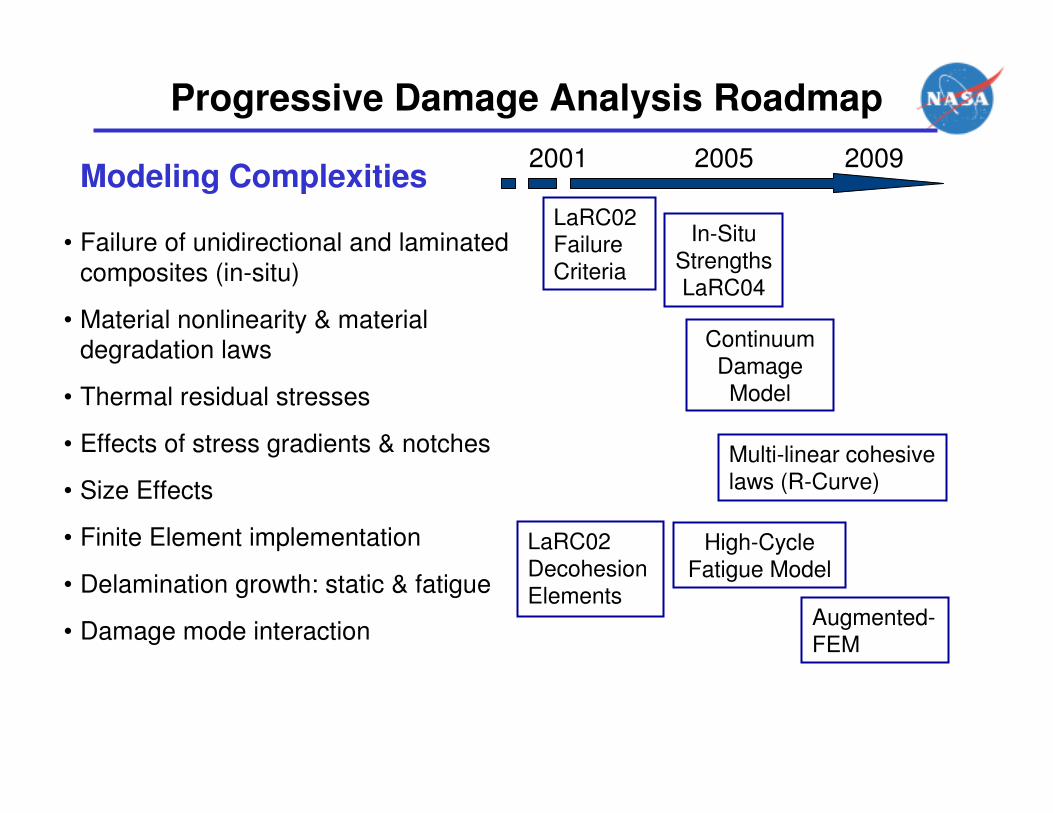
Progressive Damage Analysis Roadmap
Modeling Complexities
• Failure of unidirectional and laminated
composites (in-situ)
• Material nonlinearity & material degradation laws
• Thermal residual stresses
• Effects of stress gradients & notches
• Size Effects
• Finite Element implementation
• Delamination growth: static & fatigue
• Damage mode interaction
LaRC02 Failure Criteria
LaRC02 DecohesionElements
High-Cycle Fatigue Model
Continuum Damage Model
In-Situ StrengthsLaRC04
Augmented-FEM
Multi-linear cohesive laws (R-Curve)
2001 2005 2009
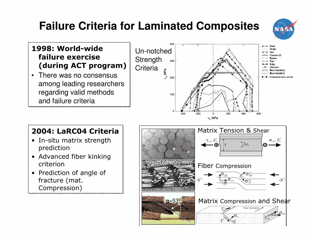
Failure Criteria for Laminated Composites
σ 11σ 11
σ22σ 22
m
m
-XC-X
C
ϕ
2a0
σ22
, YT
tτ 12, S
L
is is
αααα=53º
τL
τT
σn
σ22
τ12α
Fiber orientation
Matrix Tension & Shear
Fiber Compression
Matrix Compression and Shear
2004: LaRC04 Criteria
• In-situ matrix strength prediction
• Advanced fiber kinking criterion
• Prediction of angle of fracture (mat.Compression)
2004: LaRC04 Criteria
• In-situ matrix strength prediction
• Advanced fiber kinking criterion
• Prediction of angle of fracture (mat.Compression)
1998: World-wide failure exercise (during ACT program)
• There was no consensus among leading researchers
regarding valid methods
and failure criteria
1998: World-wide failure exercise (during ACT program)
• There was no consensus among leading researchers
regarding valid methods
and failure criteria
Un-notched
Strength
Criteria
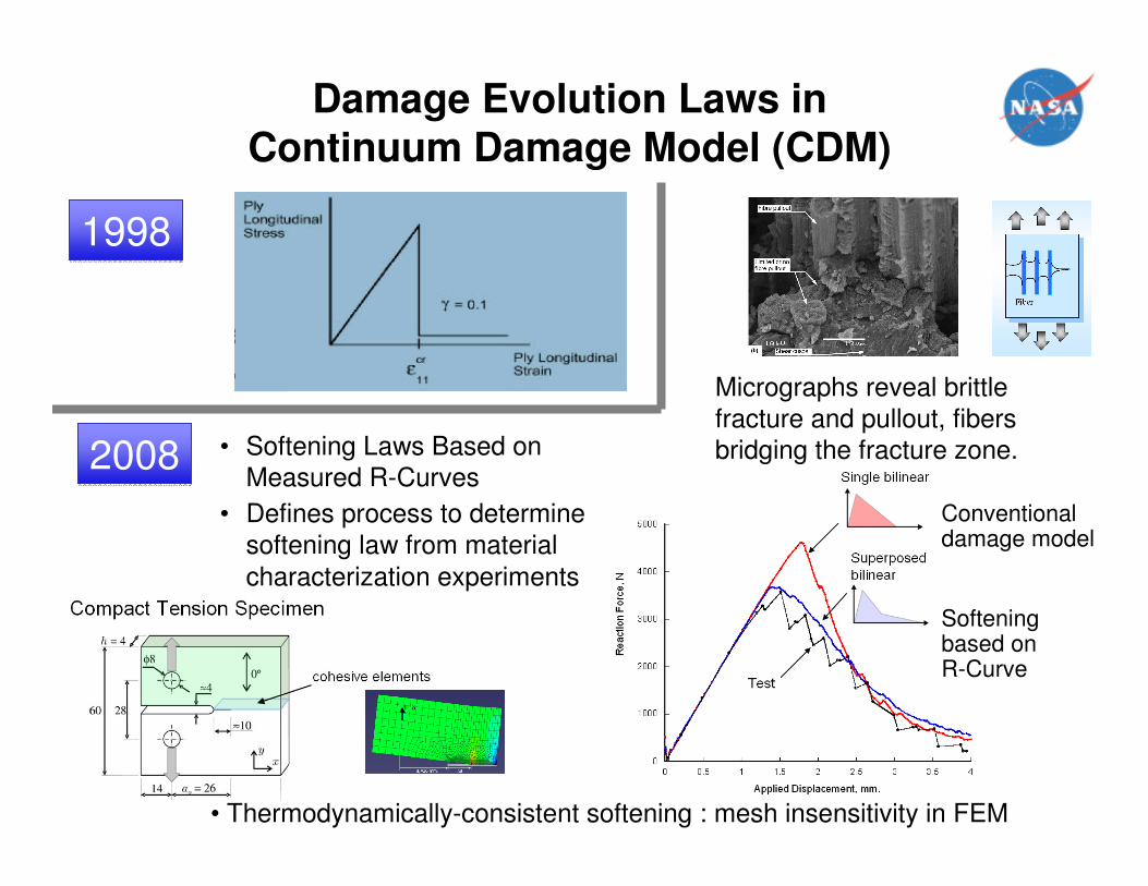
Damage Evolution Laws in
Continuum Damage Model (CDM)
Conventional damage model
Softening based on R-Curve
Micrographs reveal brittle
fracture and pullout, fibers
bridging the fracture zone.
19981998
• Softening Laws Based on Measured R-Curves
• Defines process to determine
softening law from material
characterization experiments
20082008
• Thermodynamically-consistent softening : mesh insensitivity in FEM
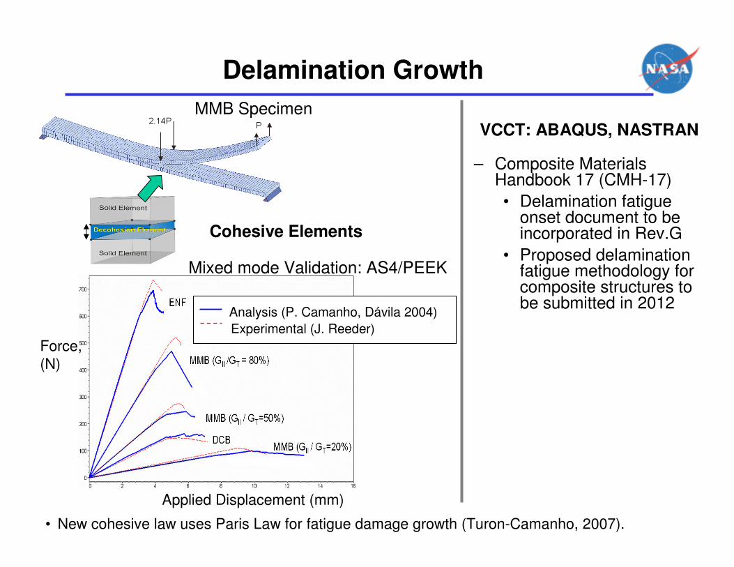
Delamination Growth
MMB Specimen
Mixed mode Validation: AS4/PEEK
Applied Displacement (mm)
Force,
(N)
Analysis (P. Camanho, Dávila 2004)
Experimental (J. Reeder)
Cohesive Elements
• New cohesive law uses Paris Law for fatigue damage growth (Turon-Camanho, 2007).
VCCT: ABAQUS, NASTRAN
– Composite Materials Handbook 17 (CMH-17)
• Delamination fatigue onset document to be incorporated in Rev.G
• Proposed delamination fatigue methodology for composite structures to be submitted in 2012
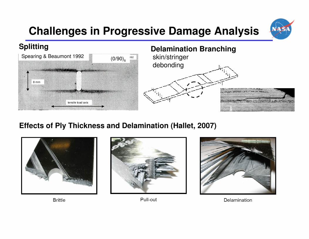
Challenges in Progressive Damage Analysis
tensile load axis
8 mm
Spearing and Beaumont, 1992Spearing & Beaumont 1992 (0/90)s
Splitting
Effects of Ply Thickness and Delamination (Hallet, 2007)
Delamination Branchingskin/stringer debonding
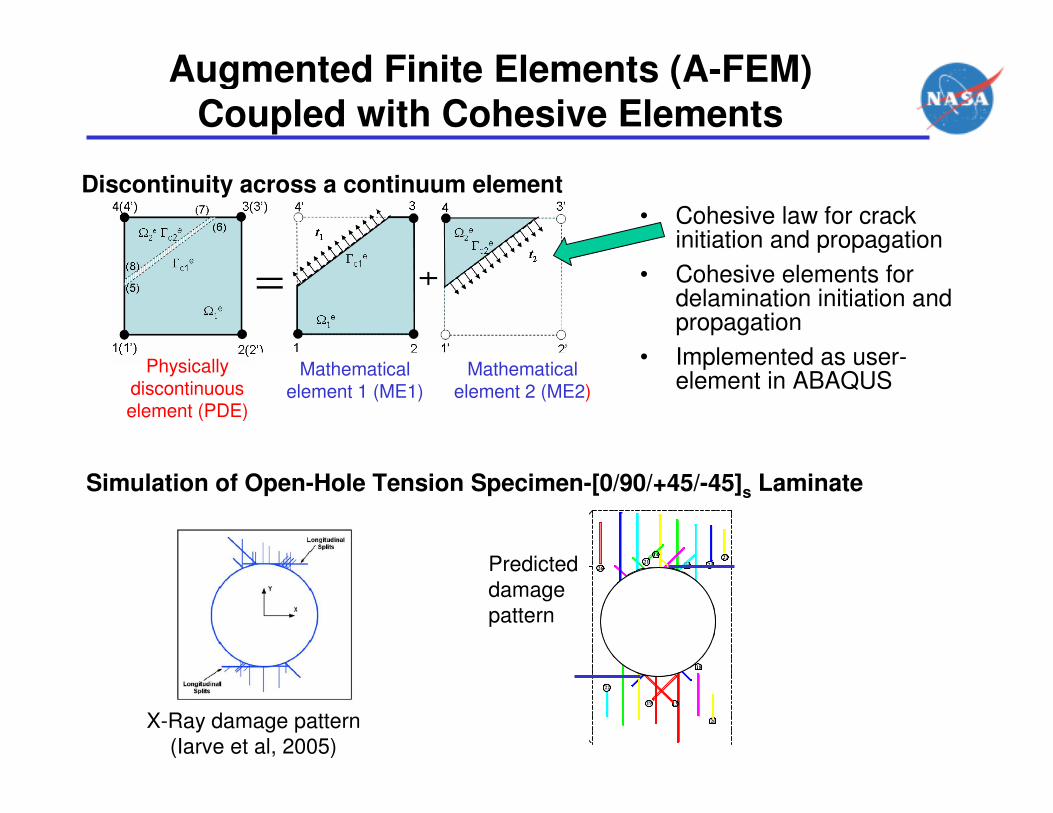
Augmented Finite Elements (A-FEM)
Coupled with Cohesive Elements
Discontinuity across a continuum element
Physically discontinuous element (PDE)
Mathematical element 1 (ME1)
Mathematical element 2 (ME2)
• Cohesive law for crack initiation and propagation
• Cohesive elements for delamination initiation and propagation
• Implemented as user-element in ABAQUS
Simulation of Open-Hole Tension Specimen-[0/90/+45/-45]s Laminate
X-Ray damage pattern
(Iarve et al, 2005)
20
18117
1319
158
22
15
27
23
16
10
32 6
14
21
9412
17
26Predicted
damage
pattern
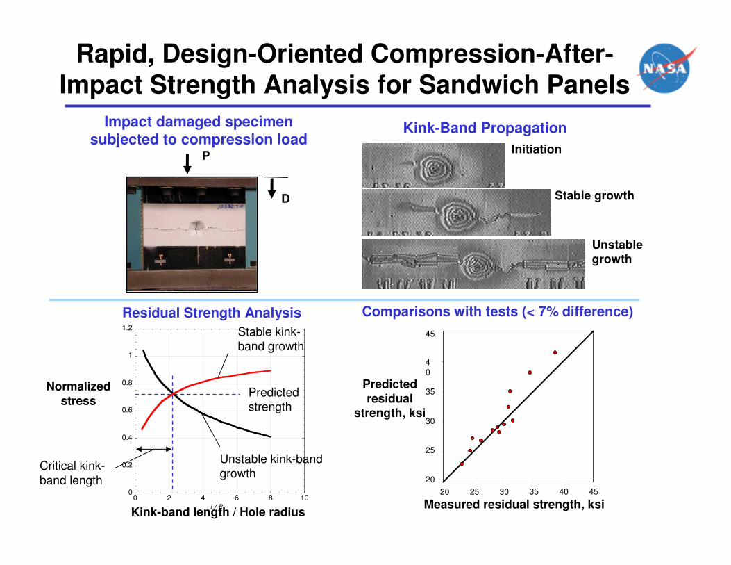
Rapid, Design-Oriented Compression-After-
Impact Strength Analysis for Sandwich Panels
Kink-Band Propagation
Residual Strength Analysis Comparisons with tests (< 7% difference)
Impact damaged specimen
subjected to compression loadInitiation
Stable growth
Unstable
growth
Kink-band length / Hole radius
Unstable kink-band
growth
Stable kink-
band growth
Predicted
strength
20
25
30
35
40
45
20 25 30 35 40 45
40
35
30
25
20
45
4020 25 30 35 45
Predicted
residual
strength, ksi
Measured residual strength, ksi
P
D
0
0.2
0.4
0.6
0.8
1
1.2
0 2 4 6 8 10l / R
Critical kink-
band length
Normalized
stress
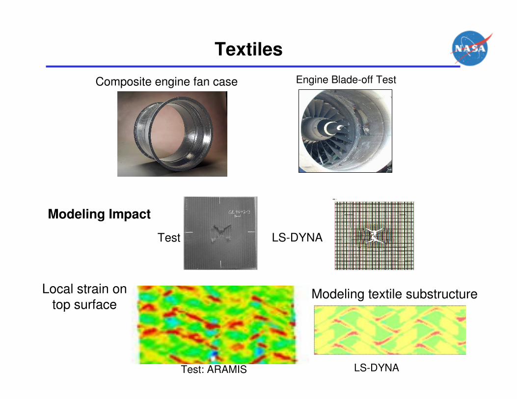
Textiles
Composite engine fan case
Test: ARAMIS LS-DYNA
Local strain on top surface
LS-DYNATest
Engine Blade-off Test
Modeling Impact
Modeling textile substructure
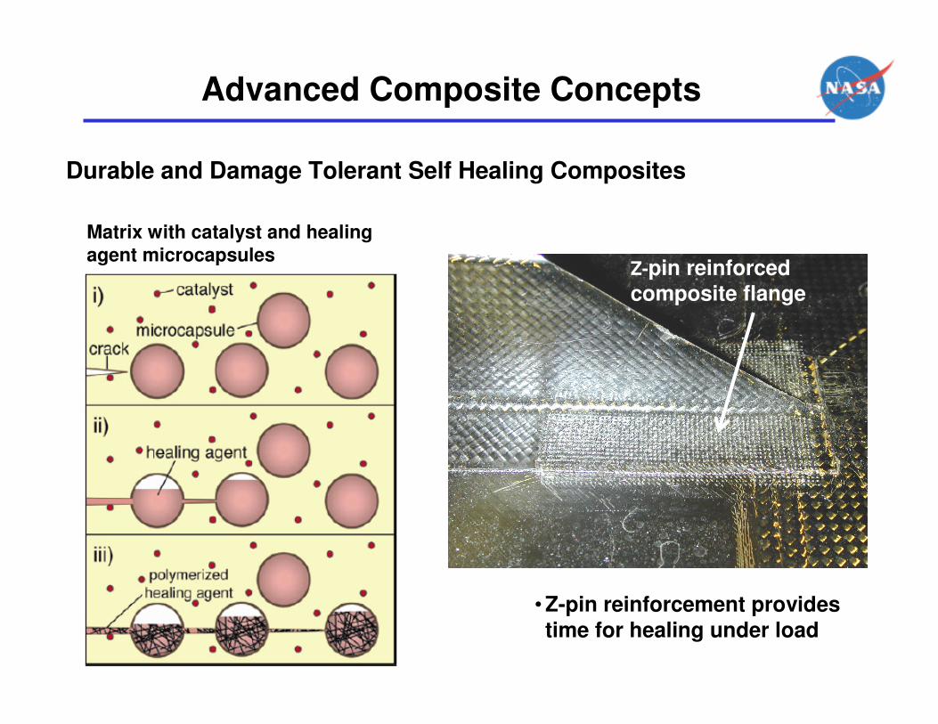
Advanced Composite Concepts
Durable and Damage Tolerant Self Healing Composites
• Z-pin reinforcement provides
time for healing under load
Matrix with catalyst and healing
agent microcapsulesZ-pin reinforced
composite flange

Advanced Composite Concepts (cont.)
PRSEUS (Pultruded Rod Stitched
Efficient Unitized Structure)
• Arrested damage
enables fail-safe
design philosophy
Displacement
Linear
Threshold
Net Section Failure
Damage
Arrest
Limit
Ult
Cyclic
Damage Growth
Load
Next Nonlinear
Event
PultrudedRod
(0� Fibers)
2 Rows ofStitching
Warp-knit Fabric Wraps Around Rod
2 Rows Web Stitching
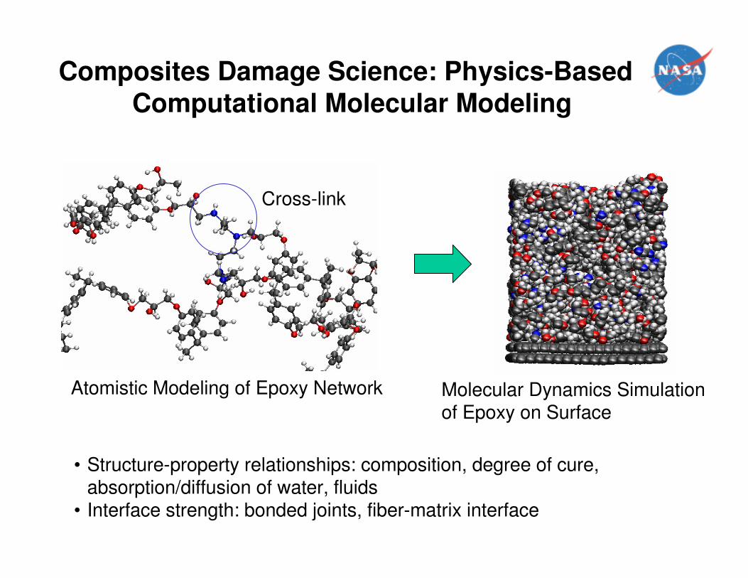
Composites Damage Science: Physics-Based
Computational Molecular Modeling
Cross-link
Atomistic Modeling of Epoxy Network Molecular Dynamics Simulation of Epoxy on Surface
• Structure-property relationships: composition, degree of cure, absorption/diffusion of water, fluids
• Interface strength: bonded joints, fiber-matrix interface
Summary
• Technology development programs 1980’s and 1990’s
• Manufacturing, proof of damage tolerance, repair substantiation
• Successes … but several premature failures attributed to details
• Composites have complex failure modes, unique challenges
• Building-block design approach, enhanced by analysis
• Early Damage Tolerance methods emperically-based
• Progressive Failure Analysis methods are maturing
• Damage tolerant concepts are being studied
• Long term composites damage science research initiated

![[NASA] - NASA-CR-197172 Cabin-Fulsage-Wing Structural Design Concept With Engine Installation](https://img.dokumen.tips/doc/110x75/552906b44a795981158b45c3/nasa-nasa-cr-197172-cabin-fulsage-wing-structural-design-concept-with-engine-installation.jpg)