Embed Size (px)
Citation preview

NASA CR-167955 ~ 8 1 ~ ~ ~ 2 8 4 '
Netha! Aeronautics and Space Administratfan
ENERGY EFFICIENT ENGINE
High Pressure Tvrbine Test Hardware Detailed Design Report
E.E. Halila D.T. Lenahan T.T. Thomas
GENFIRAL.ELECTRIC COMPANY
June 1982
LIBRARY EBPY
MNGLEY RESEAHI:H CENTF-R LIBRARY. NASA
HAMPPON, VIRGINIA Prepared For
NASA Lewis Research C 9 N , r L -.
https://ntrs.nasa.gov/search.jsp?R=19850002687 2018-09-26T23:28:24+00:00Z
r
1. Report No 7 2. Gov~rnment Accru~an No. NASA CR-lb7355
4, T~tle and Subtitle
7. Authorts) 8. Performing Organization Report No.
3. Recipient's Catalog No.
5. Report Date
I ENERGY EFFICIENT ENGINE IIICiIt PRESSURE TURDINE TEST HARDWARE DETAILED DESIGN REPORT
1 E , E . H a l l l a , D.T. Lcnahsn, and T.T. Thomas
June 1982 6. Performing Organization Code
Gcncral E l e c t r i c Afrc rnf t Engine Business Group Advanced Tcchnolofiy Programs Department Cincinnati, Ohio 45215
Name rod Address
11. Contract or Grant No.
NASZ. 20643
10. Work Unit No.
1 l* Typn of Report and Period Covered
12. Sponsoring Agency Nome md Addrms I I I Nntionnl Aeronnutics and Space Administrnt ion
Lewis Iiescnrch Contcr 14. Spor.soring Agency Code
Cleveland, Ohio 44135 I i 'IS. Supplementary Notas
I NASA P r o j e c t Manager: C.C. Ciep lvrh G.E, Project Manager: R.W. hucy I
The high pressure t l ~ r k i n c confi.c,urrition for the Energy E f f i c i e n t Engine (E?) is b u i l t around a two-stage d e s i g n system. l lodera te aerodynamic load ing for ho th s t a g e s is used t o ach ieve the high level of tu rb ine e f f i c i e n c y .
Flowpach components are designed For 18,000 hours of l i f e . while the s t a t i c and r o t a t i n g s t r u c - tu res are d e s i ~ n e d f o r 36,000 hours o f engine opcrn t fon , Both s t a g e s of t u r b i n e b l a d e s and vanes a r e air-cooled i n c o r p o r a t i n g advanced s t a t e o f the a r t i n c o o l i n g technology. Direct s o l i d f f i c n t i o n (DS) a l l o y s a r e used f o r blades and one s t a g e of vanes , and an oxide dispersion syntem (ODs) o l l o v is used f o r the Staqe I nnz7le a i r f o i l s . Ceramic s h r o ~ ~ d s a r p used as t h e m a t e r i a l composition f o r the Stage 1 shroud.
An act ive c l e a r a n c e c o n t r o l (ACC) system Is used to c o n t r o l t h e h l a d c t i p to shroud c l e a r a n c e s f o r both stages. Fan a i r is used to impinge on the shroud cns11.l: support: r i n g s , thereby con- t r o l l i n g t h e growth r a t e of the shroud. This procedure a l lows close c l e a r a n c e c o n t r o l whilc minimizing b l a d e t i p to shroud rubs .
OR1GINAL PAGE FS OF POOR QURI..!T\;
117. Key Words (Suggested by AuthorId1
Two-Stage, High Pressure Turbine Energy E f f i c i e n t Engine Turbofan Engine
NASA-C-168 (Rev. 10-75)
19. Security C I P ~ . ' sf this report)
U n c l n ~ s ~ i i t ,
20. Security Classif. (of this pagel
Uncl nssif l e d
21. No. of Pages
186
22. Price'

TABLE OF CONTENTS
Sect ion
1.0 INTRODUCTION AND SUMMARY
2.0 AERODYNAMIC DESIGN
2. L Performance Requirements 2.2 Design S t u d i e s
2.2.1 Number of S t a g e s 2.2.2 Diameter 2.2.3 Annulus Height 2.2.4 Stage Work D i s t r i b u t i o n
2.3 Detailed Aerodynamic Design
2.3.1 Airfoil Design A n a l y s i s 2 . 3 . 2 E f f i c i e n c y P r e d i c t i o n and Verification
3 .O COOLING SYSTEM DESIGN
3.1 Fea tu res and Development
3 . 1 . 1 General D e s c r i p t i o n 3.1.2 Trade S t u d i e s and Heat Transfer 3.1.3 Cooling-Supply System and Flows 3 . 1 . 4 F l i g h t M i s s i o n
3 . 2 Deta i l ed Cooling System and Heat T r a n s f e r Design
3.2.1 S t a g e I Nozzle 3 . 2 . 2 Stage 1 Rotor 3 . 2 . 3 Stage 1 Shroud 3 . 2 . 4 Stage 2 Nozzle 3.2.5 Stage 2 Rotor 3.2.6 Stage 2 Shroud 3 . 2 . 7 Rotor Structure 3 . 2 . 8 Casing 3 .2 .9 Stage 1 Nazzle Suppor t System
4.0 ACTIVE CLEARANCE CONTROL SYSTEM
4 . 1 General D e s c r i p t i o n 4.2 De ta i l ed Design and Features 4.3 Mechanical Qesign C o n s i d e r a t i o n s
5 .O MECHANICAL DESIGN
5.1 General D e s c r i p t i o n
5.1.1 C o n f i g u r a t i o n 5.1.2 M a t e r i a l s S e l e c t i o n 5.1.3 A n a l y t i c a l Methods
Page
I,

TABLE OF CONTENTS /Concluded)
Sect ion Page - 5 .I, 3 .l Computer Programs 5.1.3.2 Procedures
5.1.4 Design C r i t e r i a 103
5 . 2 Detai led Mechanical Design 105
5.2.1 Rotor Components: Stress, S t r e s s Concentration, ECF Life i 0 5
5.2.1.1 Forwar..! HP Shaft and Outer Liner 5.2.1.2 Inducer Disk 5.2.1.3 Impeller and S t a g e 1 Retention System 5.2.1.4 Stage 1 Disk 5.2.1.5 Inters tage Seal Disk 5.2.1.6 Stage 1 and 2 Blade Retainers 5.2.1.7 Stage 2 Disk 5.2.1.8 A f t Shaft/Seal Disk 5.2.1.9 S t a g e 1 Blade 5.2.1.20 Stage 2 Blade 5.2.1.11 Dynamic Analysis 5.2.1.12 B o l t Design
5 .2 .2 Sts t i c Components : Stress, Stress Conc:entration, LCF E i f e 150
5.2.2.1 Caslngs 5.2 .2 .2 Stage I Nozzle Support 5.2.2.3 S t a g e 1 Nozzle 5.2.2.4 Stage 2 Nozzle
5.2.3 Ceramic Shrouds 167
5.2.3.1 General Description 5.2.3.2 Design and Analysis
5.3 Maintainabil i ty 17 3
5.4 FPS AssembP, Weight 179
REFERENCES 181
SYMBOLS AND TERMS 183

LIST OF ILLUSTRATIONS
Figure
Annulus Trade Study . Stage qork Di s t r ibu t ion .
Turbine Aerodynamic Flowpath,
Axisymmetric-Flow Analysis Model.
Blading Parameters.
A i r f o i l Shapes and V e l o c i t y D i s t r i b u t i o n s ,
Warn A i r Turbine Rlg . Blade - J e t Speed Performance ~ n d Subidle Mapping, Ef f ic iency Versus Velocity Rat io .
Heat ~ r a n s f e r / C o o l i n g Design Features .
E f f e c t of T 4 1 on SFC.
Rotor and Casing Cooling-Supply System.
F l i g h t Cycle Mission.
Staqe I Vane.
Stage I Nozzle Impingement Baffles . Stage 1 HPT V a n e Cooling Geometry.
Stage 1 Vane Thermal Model and Deta i led Temperature D i s t r i bu t ion .
Stage 1 HPT Vane Cooling Air Mfxing Losses.
Stage 1 Vane, Inner Band.
Stage 1, Nozzle Outer Band H e a t Transfer Design,
Turbine Rotor Cooling Source.
Stage I Blade Design Features .
Stage 1 Blade Pitch-Line Mach Number Di s t r ibu t ton .
Externa l Heat Transfer Coeff ic ien t .
Stage 1 B l a d e Cooling System.
Stage 1 Blade T i p Cap Cooling Design.
Stage 1 B l a d e Flow Charac t e r i s t i c s .
Stage 1 Blade P i t ch -L ine Temperature D i s t r i b u t i o n st Steady- S t a t e Takeoff.
Stage 1 Blade Transient Thermal Analysis ,
Stage 1 Shroud - Cooling Geometry.

LIST OF ILLUSTRATIONS (Continued)
Page Figure
30. Stage J. Shroud Temperature D i s t r ibu t ion .
Stage 2 Nozzle Design Features .
Stage 2 Nozzle Cooling Flows.
Stage 2 Vane Temperature D i s t r ibu t ion .
Stage 2 Blade Design Fea tures .
Srage 2 Blade Pitch-Line Temperatures a t Steady-State
Stage 2 Slade Leading Edge'FOD Temperatures.
Rotor S t ruc tu re Deta i led Heat Transfer Model.
I n t e r s tage Seal Disk.
Casing Cooling Flow D i s t r i b u t i o n .
Casing Steady-Stare Takeoff Temperature D i s t r ibu t ion .
Active Clearance Control Operation,
HPT/LPT ACC Cooling System.
Active Clearance Control Design Features.
Stage I Blade-Tip Clearances.
I n t e r s t a g e Seal Clearances.
Srage 2 Blade-Tip Clearances.
Blade-Tip Clearance Reduc thn wi th ACC.
Active Clearance Control Design,
ACC Impingement Manifold Ci rcumferent ia l Arrangement.
g3 HPT Major Design Features .
Material Se lec t ions f o r Rotor Components.
Ma te r i a l Se lec t ions f o r S t a t i c Components.
~akeoff /Cl imb/Cruise Trans ien t Parameters.
Rotor Temperature D i s t r ibu t ion .
CLASS/MASS Ef fec t ive S t r e s s .
E~ High Pressure Turbine.
Forward Sha f t and Outer Liner .
Inducer Disk.
CLASS/MASS Impeller Model.
Impeller Loads, E f f e c t i v e S t r e s ses , and Temperatures.
51
52
53
55
57 Takeoff . 58
60
63
64
6 6
67
70
70
7 2
7 4
7 5
76
78
81
82
87
91
9 2
100
101
102
106
107
107
109
110
Figure
LIST OF ILLUSTRATIONS (Continued)
Page
Stage 1 Disk S t r e s s Concentration and LCF L i f e . 111
Stage 1 Disk Dovetai l ~ l a s t i c l ~ l a s k i c (FINITE) S t r e s s Analy s f s . 113
Stage 1 Disk Finite-Element Model. 114
Stage 1 Disk ~ t r e s s / ~ i f e . 115
Interstage Seal Disk F i n i t e E f fec t ive S t r e s s Distribution, Temperature, and LCF Life. 116
HP Turbine Bo l t l e s s Retainer Design Fea tures . 11 7
Stage 1 Aft Blade Retainer Temperature and S t r e s s P r o f i l e . 119
Stage 2 A f t Blade Retainer Temperature and S t r e s s P r o f i l e . 120
Stage 2 Disk S t r e s s Concentration and LCF Life. 1 2 1
Stage 2 D i s l c Dovetail E l a s t i c / P l a s t i c (FINITE) S t r e s s Analysis. 122
E l a s t t c / P l a s t i c Stress Analysis (CYANIDE). 123
A f t Seal Disk (Growth Engine) E l a s t i c (FINITE) Stress Analysis. 124
Stage 1 B l s d e Design Features . 125
Mission-Mix Flight for Ambient Temperature Conditions. 128
Stage 1 Blade, BUCKET-CREEP Pro3ran1 Model (Pitch Section). 129
S tage 1 Blade-Five Sect ion, Rupture Life Including Creep Effects on Reduction of Blade Tilt. 131
FPS Base Stages 1 and 2 Blade Trans ien t Cycle. 132
FPS Base Stage 1 Blade Trans ien t Analysis ( P i t 1 5 Section).
FPS Base Stage I Blade Thrust Reverse Transier- t S t r e s s f o r Leading Edge a t Pitch Section.
FPS Base Stage 1 Blade Campbell Diagram.
Stage I Blade Dovetai l S t r e s s .
Stage 2 Blade Design Fea tures .
Stage 2 Blade BUCKET-CREEP Program Model.
Stage 2 Blade Pitch-Section Rup.ture L i f e .
FPS Base Stage 2 Blade Campbell Diagram.
Stage 2 Blade Seal Damper.
Stage 2 Blade Dovetai l Stresses.
Aft-Seal Disk Frequency or Free Vibrat ion.
Rotor Bolt Flanges.

LIST OF ILLUSTRATIONS (Concluded)
Induc ?r D.isk Bolt Relaxation Analysis.
FPS Growth-Engine Interstage-Seal llisk Relaxation Analysis.
Static Components and Assembly Arrangement.
Casing LCF Life, Stress, and Temperature at Hot-Day Maximum Takeoff.
FPS Growch Engine Inner Nozzle Support.
111ducer and Piston Balance Seal Configuration.
Inducer and Piston Balance Seal Stresses.
Stage 1 Vane Manufacturing.
Stage 1 Nozzle Design Features .
FPS Base Stage 1 Inner Nuzzle Flange S t r e s s .
Stage 1 Vane Suction-Side Panel Creep Bulge Versus Time.
Stage 1 Nozzle AirfoF1 LCF Life at 65% Span at Maximum Takeoff Condition (Table XX) . Stage 2 Nozzle Design Features.
Stage 2 Nozzle Airfoil Design Features.
Stage 2 ~frfoil LCF L i f e .
Stage 2 HP Nozzle Stresses Due to Gas Loads.
Page
Ceramic Shroud. 172
Stage 1 Shroud Temperature Versus Thickness of Ceramic Layer. 174
Ceramic Shroud Thickness Bll.>wance for Engine Stackup. 17 5
Ceramic Shroud Stres s fL i f e . 176
Stage 1 Nozzle/Combustor/Diffuser Module Assembly. 17 7
Stage 2 Nozzle and Shroud-Support Casing Eodule Assembly, Engine Level. 178
HP Turbine Rotor Module Assembly, 180

LIST OF TABLES
Table -
V I X .
XLI.
XIV .
XVI . XVII.
XVIII.
XLX.
XX.
HPT Aero-Thermodynamic Design Requirements.
Single-Stage Versus Two-Stage Turbine .
S t a g e Aerodynamics Summary.
Blading Aerodynamic Geometry.
E f f i c i e n c y E s t i m a t e .
T41 Margin Def in i t i on .
Cooling and Leakage FLOWS.
Heat-Transfer Design Parameters .
S tage 1 Vane c o o l i n g Faramete t s .
A c t i v e Clearance Cont ro l System Payof f .
Maximum Takeoff Clearance After Shor t S t a r t .
Maximum TakeofP Pinch Clearance Witti External Heating During Warm Up.
Stage 1 Clearance Change f o r Maximum Closure .
B lade-~ ip /Shroud Clearance .
Component Design Lives.
Rotor and S t a t o r Materials.
A n a l y t i c a l Computer Methods.
F l igh t Timed for Rotor Analysis.
Design Miss ion Cycle ,
Stage 1 HPT Blade Mission Mix Summary.
Stage 2 HPT Blade Mission Mix Summary.
Dynamic Analysis.
FPS Weight Data Base.
Page
4
5
10
12
15
20
2 5
27
29
7 3
7 7

1 . 0 INTRODUCTION AND SUMMARY
Tha General E l e c t r i c Energy E f f i c i e n t Engine ( ~ 3 ) High P r e s s u r e Turbine (HPT) r e p r e s e n t s odvat~ced t t!chtiology aimed at ach iev ing h i g h e f f i c i e n c y whi le s t i l l meeting t h e component o b j e c t i v e " l i v e s " r e q u i r e d f o r c o m e r c i a l a p p l i c a - t i o n s ,
The t u r b i n e des ign evolved from o v e r a l l e n g i n e - i n t e g r a t i o n and sys tems s t u d i e s conducted by t h e Genera l E l e c t r i c Company f o r NASA (References 1 through 5 ) . These programs s t u d i e d improvements and e v a l u a t e d f o u r promis ing eng ine c o n f i g u r a t i o n s , The e v a l u a t i o n of t h e s e engine c o n f i g u r a t i o n s deve l - oped technology and r e f i n e d advanced eng ine c y c l e s and concep tua l d e s i g n s (Reference 6 ) . Advanced f e a t u r e s f o r t h e t u r b i n e des ign were developed w i t h i n the Reference 6 work e f f o r t : d i r e - t i o n a l l y s o l i d i f i e d (DS) a l l o y s fo r b l a d e s , expander c o o l i n g system f o r a two-stage t u r b i n e , a c t i v e c l e a r a n c e c o n t r o l (AcC), ceramic shrouds , and h i g h - s t r e n g t h a l l o y s with low c o e f f i c i e n t s f o r the rmal expans ion.
The ~3 Pre l iminary Design and I n t e g r a t i o n S t u d i e s (Reference 6 ) com- b i n e d and i n t e g r a t e d t h e t echno log ies developed i n t h e programs c i t e d above. T h i s s tudy e s t a b l i s h e d the background f o r the des ign nf t h e HPT under t h e p r e s e n t c o n t r a c t F u r t h e Design, Component I n t e g r a t i o n , find T e s t Program.
The HPT work scope covered a l l technology d i s c i p l i n e s r e l a t e d t o h i g h t u r b i n e e f f i c i e n c y . These i n c l u d e aerodynamics, mechanics, h e a t t r a n s f e r , me ta l lu rgy , manufactur ing, and t e s t s . T u r b i n e performance e f f o r t s a r e a i m d a t ach iev ing a h i g h p r e s s u r e t u r b i n e efficiency of 92.4% a t Mach 0.8, 10.67-km (35,000-f t ) a l t i t u d e , s t a n d a r d day, maximum crL:ise poaer s e t t i n g . The a i r - f o i l s i n t h e two-stage t u r b i n e des ign a r e moderate ly loaded .
To e s t a b l i s h t h e l e v e l of t u r b i n e performance expected i n t h e core engine test and i n t h e I n t e g r a t e d Core and Low P r e s s u r e Spool (ICLS) eng ine t e s t s , a n a i r - t u r b i n e t e s t was planned a s p a r t of the program. The a i r - t u r b i n e program consisted of two major t e s t s , and both of t h e s e have been s u c c e s s f u l l y com- p l e t e d . The first t e s t c o n s i s t e d of e v a l u a t i n g t he S tage 1 nozz le performance i n an annu la r cascade. The r e s u l t s of t h i s t e s t were used t o compare pre- d i c t e d v e r s u s a c t u a l S tage 1 nozz le e f f i c i e n c y , The second t e s t c o l ~ s i s t e d o f runn ing both s t a g e s of nozz les and b l a d e s i n a r o t a t i n g r i g . Eva lua t ion of test r e s u l t s i n d i c a t e d a t u r b i n e e f f i c i e n c y of 92.5%; t h i s i s 0.1% h i g h e r than p r e d i c t e d For t h e FPS engine (92.4%).
The a i r t u r b i n e was b u i l t us ing the s imula ted t u r b i n e des ign f e a t u r e s s e l e c t e d f o r t h e core and ICLS engine t e s t s . T h i s p rov ides assurance t h a t t h e measured e f f i c i e n c i e s i n t h e a i r t u r b i n e can be expec ted t o be r e a l i z e d d u r i n g t h e e n g i n e t e s t s .
The o v e r a l l des ign f o r t h z high p r e s s u r e t u r b i n e c o n s i s t s of two phases as fol lows:

Phase I - Preliminary Design - Phase I design e f f o r t s t a r t e d i n January 1978 a n d ended i n April 1978. Phase I was a prel iminary ana lys i s to de f ine geoaetry and systems i n t e g r a t i o n of the two-stage tu rb ine , The i n t eg ra t ion consis ted of e s t ab l i sh ing methods f o r determining r o t o r and s t a t o r configura- t i o n s , cool ing f low, and t u r b i n e geometry. The prel iminary design was presented t o NASA, and t h e i r approval was obtained t o proceed t o Phase I1 - Detailed Design.
Phase 11 - Detailed Design - The d e t a i l e d design cons i s t ed of an e f fo r t t o integrate alL t h e experience from the material-development programs, the heat- t r a n s f e r cascade tests, the a i r - t u rb ine t e s t s , and the prel iminary mechanical and systems designs. A Deta i led Design Review of the High Pressure Turbine was presented t o NASA on October 10 , 1980, Approval was received from NASA t o procure a l l necessary hardware f o r t he core and ICLS engine tests.
AERODYNAMIC DESIGN
2 , l PERFORMANCE REQUIREMENTS
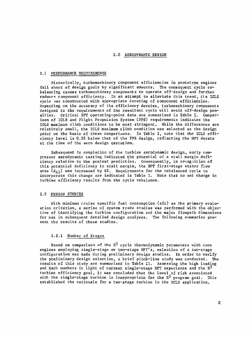
H i s t o r i c a l l y , turbomachinery compotient e f f i c i e n c i e s i n p ro to type engines f a l l s h o r t of des ign g o a l s b y s i g n i f i c a n t amounts. The consequent c y c l e re- ba lanc ing causes turbomachinery components t o o p e r a t e off -des ign and f u r t h e r reduces component e f f i c i e n c y . I n a n a t t empt t o a l l e v i a t e t h i s t r e n d , t1.e ICLS cyc le qas c o n s t r u c t e d wi th a p p r o p r i a t e d e r a t i n g o f component e f f i c i e n c i e s . Depending on the accuracy o f t h e e f f i c i e n c y d e r a t e s , turbomachinery components designed t o t h e requ i rements o f t h e r e s u l L a n t c y c l e w i l l avoid off -des ign pen- a l t i e s . C r i t i c a l HPT opera t ing-po in t d a t a a r e summarized i n Table I. Compar- i s o n of ICLS and F l i g h t P rupu ls ion Sys tern (FPS) requirements i n d i c a t e s t h e ICLS maxirnum climb c o n d i t i o n s t o be most s t r i n g e n t . While t h e d i f f e r e n c e s a r e r e l a t i v e l y s m a l l , t h e ICLS maximum cl imb c o n d i t i o n was s e l e c t e d a s t h e d e s i g n point on t h e b a s i s o f t h e s e c o m p a r i ~ o n s . I n Table I, n o t e t h a t the ICLS e f f i - c iency l e v e l i s 0.5% below t h a t o f t h e FPS d e s i g n , r e f l e c t i n g t h e HPT d e r a t e a t t h e t ime of t h e a e r o d e s i g n execu t ion .
Subsequent t o complet ion o f t h e t u r b i n e aerodynamic des ign , e a r l y com- p ressor aerodynamic t e s t i n g i n d i c a t e d t h e p o t e n t i a l o f a stall margin d e f i - c iency r e l a t i v e t o t h e p r e t e s t p r e d i c t i o n , Consequently, i n r ~ s a g . ~ i t i a n of t h i s p o t e n t i a l d e f i c i e n c y i n s t a l l margin , t h e tIPT f i r s t - s t a g e s t a t o r f low a r e a (A41) was inc reased by 4%. Requiremefits f o r t h e rebalanced c y c l e t o i n c o r p o r a t e t h i s change a r e i n d i c a t e d i n Table I. No6e t h a t no n e t change i n t u r b i n e e f f i c i e n c y r e s u l t s from t h e c y c l e reba lance .
DESIGN STUDIES
With mimimum c r u i s e s p e c i f i c f u e l consumption ( s fc ) a s t h e primary evalu- a t i o n c r i t e r i o n , a s e r i e s o f system t r a d e s t u d i e s was performed with t h e objec- t i v e of i d e n t i f y i n g t h e t u r b i n e c o n f i e u r a t i o n and t h e major f lowpath dimensions for u s e i n subsequent d e t a i l e d des ign a n a l y s e s . The fo l lowing summaries pre- s e n t t h e r e s u l t s o f t h e s e s t u d i e s ,
2.2.1 Number o f S t a g e s
Based on comparison of t h e E~ c y c l e thermodynamic parameters wi th c o r e engines employing s i n g l e - s t a g e o r two-stage HPT's, s e l e c t i o n o f a two-stage c o n f i g u r a t i o n was made d u r i n g p r e l i m i n a r y des ign s t u d i e s . I n o r d e r t o v e r i f y t h e p r e l i m i n a r y des ign s e l e c t i o n , a b r i e f pitch-Line s t u d y was conducted. The r e s u l t s o f t h i s s tudy a r e summarized i n Table 11. Assess ing t h e h igh load ing and Mach numbers i n l i g h t o f c u r r e n t s i n g l e - s t a g e HPT exper ience and t h e E~ t u r b i n e e f f i c i e n c y g o a l , i t was concluded t h a t t h e l e v e l o f r i s k a s s o c i a t e d with t h e s i n g l e - s t a g e t u r b i n e i s i n a p p r o p r i a t e f o r t h e E~ program g o a l . Th i s e s t a b l i s h e d the r a t i o n a l e f o r a two-stage t u r b i n e i n t h e ICLS a p p l i c a t i o n ,
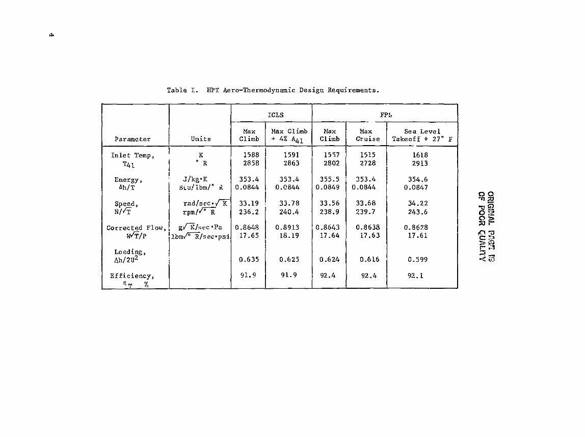

Table 11, Single-Stage Versus Two-Stage Turbine.
2.2.2 Diameter
St age
The turb ine diameter es tab l i shed during preliminary des ign , together d i t h the core engine thermodynamic parameters, r e s u l t e d i n l i g h t t o moderately loaded , low-aspect-ratio blading. A study was undertaken t o determine the b e n e f i t s t h a t might be gained by increasing the turbine diameter. Increased turb ine diameter would reduce blade loading and thereby increase e f f i c i ency . However, a l a r g e r diameter would a l s o increase weight, reduce blade aspect r a t i o , increase t i p c learance , and lead t o g r e a t e r windage e f f e c t s . The study concluded that t he efficiency t o be gained by increased tu rb ine diameter would c e r t a i n l y be diminished and poss ib ly exceeded by r e l a t e d p e n a l t i e s .
A s imi l a r s tudy was undertaken t o i nves t iga t e the b e n e f i t s t h a t might be gained from a decrease i n t u rb ine d i a , ; t e r . The object o f t h i s study was t o determine whether the small efficiency l o s s associated w i t h higher loading i n a smaller diameter tu rb ine might not be o f f s e t by a gain due t o decreased weight, increased aspect r a t i o s , and t i g h t e r t i p c learance. Reducing the diameter of t h e HPT would a l s o neces s i t a t e a reduct ion i n the Low pressure t u rb ine (LPT) diameter o r an increase i n t rans i t ion-duct length. Both of t hese changes would introduce considerable performance penalties, Bascd on t h e above r a t i o n a l e , i t was concluded t h a t the diameter s e l e c t e d i n p re l imi - n a r y des ign was s u f f i c i e n t l y c l o s e t o the optimum for t he o v e r a l l HPT/LPT sys- t e m and t h a t f u r t h e r study was unwarranted.
One-St age
1
TWO-st age*
5.01
0.92
1.36
1.2
132
24
G.57
?
1
*preliminary, f ree-vortex ca l cu la t ions
-
2 --- 2.11
0.56
0.82
0.83
9 9
1
0.41 1
Pressure Kat io
Loading, ~h j2u2
Vane Exit Mach KO.
Blade Exit Mach No.
Blade Turning
Swirl , r
Stage Exit Mach No.
2 .25
0.74
0.89
0.84
118
17
0.36
E f f:,c iency , % 92.4

2.2.3 Annuius Height
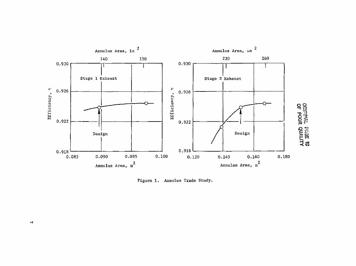
A sys tem t r a d e s t u d y o f the e f f e c t o f annu lus height was conducted by making vector-diagram c a l c u l a t i o n s i n which s t a g e - e x i t annu lus h e i g h t s were v a r i e d i n d i v i d u a l l y . The e f f e c t s on e f f i c i e n c y o f che consequent v a r i a t i o n of t i p c l e a r a n c e , a s p e c t r a t i o , edge b lockage , aerodynamic l o a d i n g , and g a s d e z l e c t i o n .ere eva lua ted by a l o s s system s e n s i t i v e t o t h e s e parameters. V a r i a t i o n i n f lowpath we t t ed area and t h e consequent e f f e c t on c o o l i n g a i r consumption and l o s s were e v a l u a t e d c o n c u r r e n t l y and inc luded i n t h e t u r b i n e e f f i c i e n c y e v a l u a t i o n . R e s u l t s o f t h e annulus-height s t u d y are summarized i n F i g u r e 1. 'he d e s i g n v a l u e s o f annu lus a r e a were s e l e c t e d s l i g h t l y below t h e optimum i n order t o minimize t h e h igh weight p e n a l t y t h a t would be imposed f o r r e l a t i v e l y s m a l l (if any) g o i n s i n e f f i c i e n c y .
7.2.4 S t a g e Work D i s t r i b u t i o n
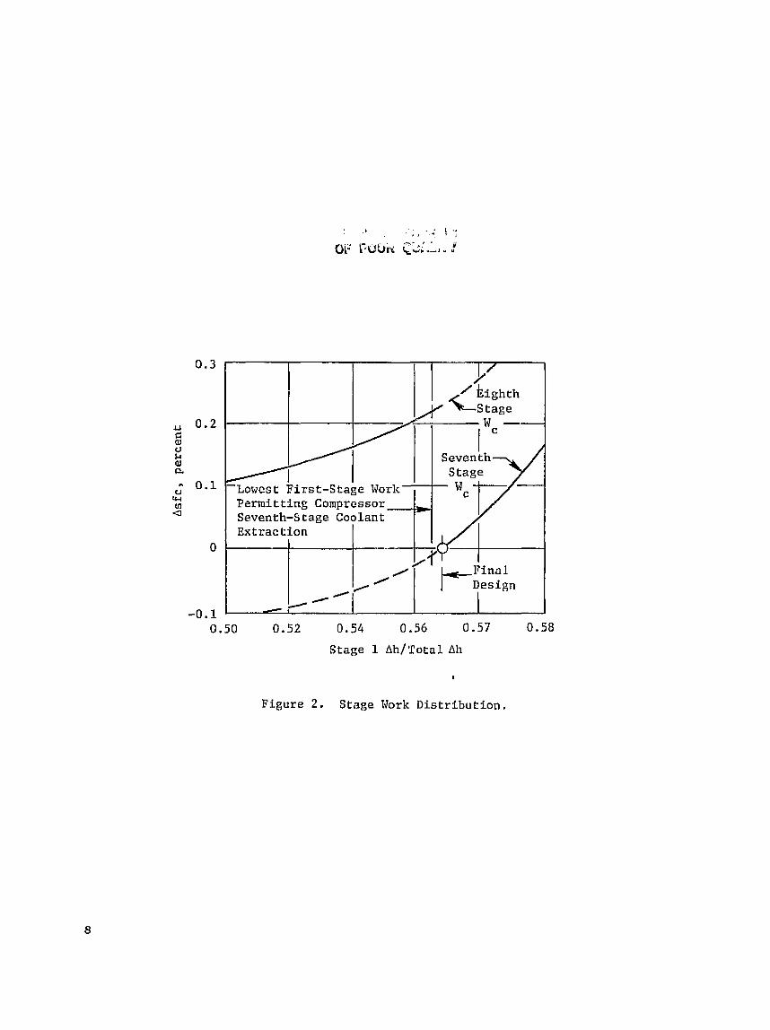
Using t h e f lowpath developed above, f u r t h e r s t u d i e s were conducted t o i d e n t i f y t h e most a p p r o p r i a t e s tage-energy d i s t r i b u t i o n . The c a l c u l a t i o n s were executed i n a manner s i m i l a r t o t h e annulus-height s t u d i e s wirh t h e e x c e p t i o n c h a t s tage-energy s p l i t was va r i ed whi le m a i n t a i n i n g c o n s t a n t b l a d e aerodynamic load in^,. The l o s s system was t h e n employed t o e v a l u a t e t h e e f f e c t on o v e r a l l e f f i c i e n c y . As wi rh t h e annulus s t u d i e s , cooling-flow v a r i a t i o n was included i n t h e o v e r a l l e f f i c i e n c y assessment . Figure 2 shows t h e r e s u l t s of these s tud ie s i n terms o f Asfc. The e f f e c t o f s tage-energy d i s t r i b u t i o n was c a l c u l a t e d assuming e x t r a c t i o n o f HPT second-stage s t a t o r c o o l i n g a i r from e i t h e r t h e s e v e n t h o r ei,hth s t a g e of the compressor. It i s seen t h a t en o p t i - mum d i s k r i h u t i o n would e x i s t a t approximate ly 48% t o 50% energy e x t r a c t i o n i n t h e f i r s t scage . However, given t h e requirement tha t the second s t a g e vane c o o l a n t supp ly p r e s s u r e exceed g a s t o t a l p r e s s u r e , i t would have been necessa ry t o s h i f t from seventh- t o e ig l , th-s tage c o o l i n g - a i r e x t r a c t i o n w i t h a n e t i n c r e a s e i11 f u e l consumption. There fo re , t h e s t a g e work d i s t r i b u t i o n was s e l e c t e d a t 56.5% i n the f i r s t s t a g e , as shown i n F igure 2 , t o improve s f c .
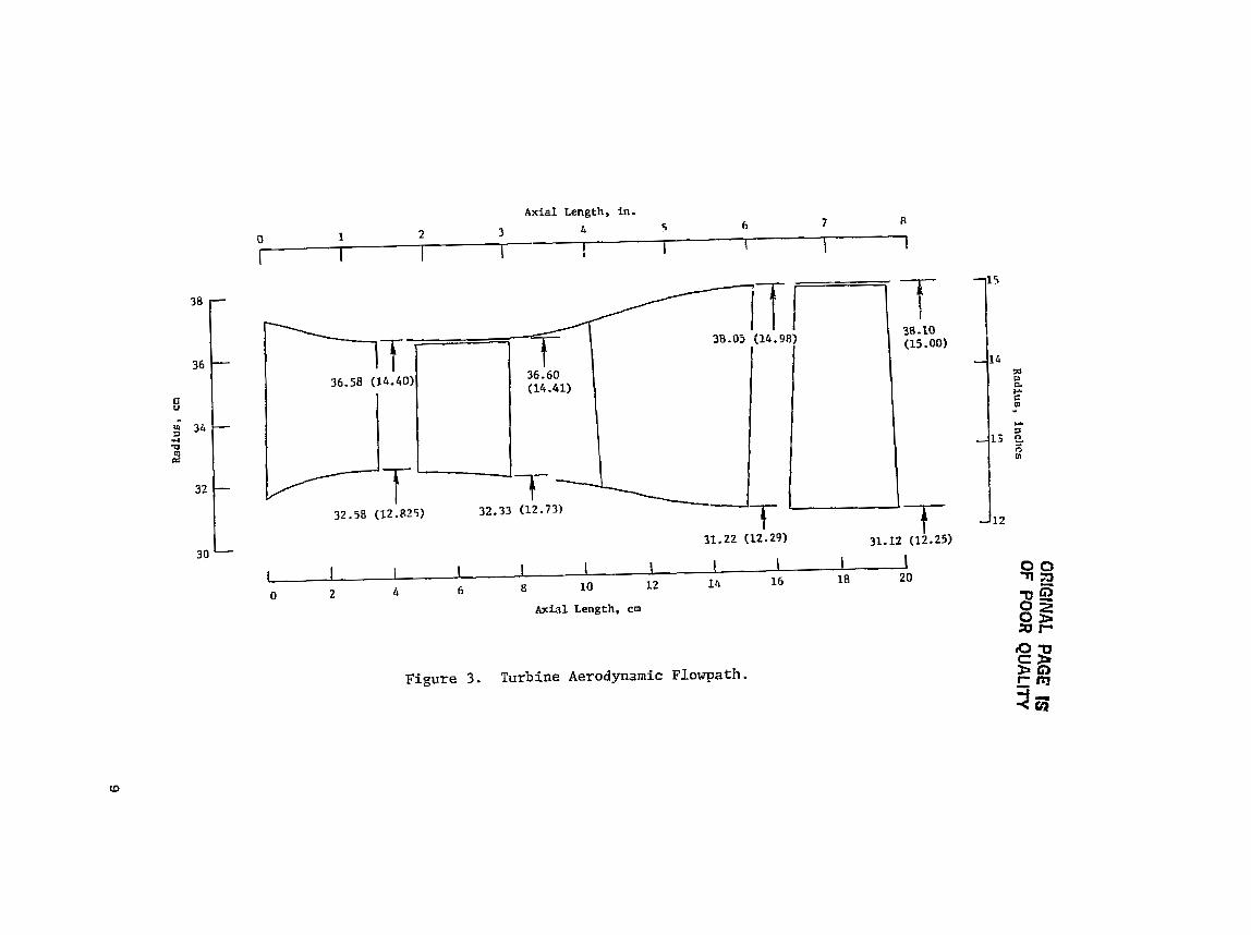
R e s u l t s o f t h e a n n u l u s - h a ~ g h t t r a d e s t u d i e s a r e summarized i n F i g u r e 3 and Table 111; turbine f lowpath geometry and s t a g e aerodynamic parameters a r e shown, r e s p e c t i v e l y . The primary f e a t u r e s o f t h e f lowpnth a r e t h e converged annulus through the f i r s t - s t a g e s t a t o r and smoothed end-wall c o n t o u r s . The s t a g e aerodynamic pa ramete r s are w e l l w i t h i n e m p i r i c a l l i m i t s e s t a b l i s h e d from o t h e r s u c c e s s f u l two-stage t u r b i n e s .
The e f f e c t s o f the 4% f i r s t - s t a g e s t a t o r flow-area i n c r e a s e were determined by o f fddes ign , vector-diagram c a l c u l a r i o n s . These c a l c u l a t i o n s are summarized by t h e v a l u e s shown i n p a r e n t h e s e s i n Table 111. The s i g n i f i c a n t aerodynamic e f f e c t s a r e i n c r e a s e d r e a c t i o n and stage work shift: toward t h e second s t a g e . These effects, a l though s m a l l , a r e i n t h e d i r e c t i o n of improved e f f i c i e n c y .
Seventh
-Lowest: First-Stage Work Permitting Compressor Seventh-Stage Coolant Extraction
Final
/ ,/ - 0.50 0.52 0.54 0.56 0.57 0.58
Stage 1 Ah/Total Ah
Figure 2. Stage Work Distribution.
Radius, Inclics
OR
PlNA
L PAGE IS
OF PO
OR
QU
ALlrY

Table 131. St age Aerodynamics Summary,
DETAILED AERODYNAMIC DESIGN
St age
The o b j e c t i v e o f t h e d e t a i l e d aerodynamic-design a n a l y s i s was t o o b t a i n d e t a i l e d geometry s p e c i f i c a t i o n s of t h e flowpath and a i r f o i l s f o r use i n demonstrator-engine hardware f a b r i c a t i o n . This p rocess was based on flowpath and o t h e r aerodynamic d a t a e s t a b l i s h e d i n t h e d e s i g n t r a d e s t u d i e s . The des ign p r o c e s s c o n s i s t e d o f a through-flow o r vector-diagram a n a l y s i s , f o r the purpose of . e s t a b l i s h i n g r a d i a l g r a d i e n t s o f f low p r o p e r t i e s c o n s i s t e n t wi th Loss and d e s i r e d work g r a d i e n t s , foLlowed by t h e a i r f o i l d e s i g n a n a l y s i s i n which f i n a l a i r f o i l geometry was determined.
Parameter
P r e s s u r e Ra t io
hh/2u2
T i p Speed ( T a k e o f f ) , m/sec f t / sec
Cooling and Leakage, %W2C
E x i t Mach No,
React ion
S w i r l , Degrees
Number of Vanes
Number of Blades
Radius R a t i o , Dn/Dt
X Tip Clearance
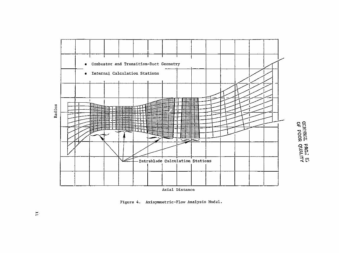
The gas p a t h through-flow o r vector-diagram a n a l y s i s was accomplished u s i n g a procedure t h a t s o l v e s t h e f u l l , three-dimensional , r a d i a l - e q u i l i b r i u m e q u a t i o n f o r axisymmetric f low. The procedure accounts f o r s t r e a m l i n e s l o p e and c u r v a t u r e , e f f e c t of t h e radial blade-force component d a t a t o a i r f o i l sweep and d i h e d m l , a i r f o i l b lockage, and r a d i a l g r a d i e n t of f low p r o p e r t i e s . C a l c u l s t i o n s were made with r a d i a l g r a d i e n t s o f b l a d i n g l o s s e s , t o s i m u l a t e end- loss e f f e c t s , and a l s o wi th l o c a l f low a d d i t i o n t o s i m u l a t e e j e c t e d - f i l m c o o l i n g . Temperature, d i l u t i o n , and momentum-mixing l o s s e s a s s o c i a t e d wi th cooling-flow i n j e c t i o n were accounted f o r w i t h i n the c a l c u l a t i o n . The ca lcu- l a t i a n model f o r t h e E~ HPT, showing merid iortal s t ream1 i n e s and in t r i tb lade- row c a l c u l a t i o n s t a t i o n s , i s shown on F igure 4. F i n a l f low angle Mach
inc reased by 4%. -
1
2.25
0.74
1"
(2.18)
(0,691
513.9 1686
535.2 1756
2
2 .11
0.56
2*
(2,181
(0.56)
0.34
0.34
16
(0 .43 )
(0 .35 )
(1)
46
7 6
0.88
1.0
18.2
48
70
0.82
0.6
( 0 . 3 4 )
(0.38)
(15)
0.42
0.33
0

ORIGINAL PAGE IS OF POOR QUALITY
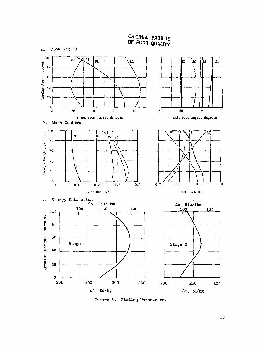
numbers and energy e x t r a c t i o n d i s t r i b u t i o n s a r e sumlnarized i n Figure 5. The ove ra l l g r ad ien t s charoc t e r i z e the forced-vortex flow d i s t r i b u t i o n and small g rad ien t s i n s tage energy e x t r a c t i o n . The e f f e c t of l o s s g rad ien t s i s seen i n l o c a l angle and Mach number v a r i a t i o n s ad jacent to the end walls. These d a t a served as boundary condi t ions f o r t he a i r f o i l design ana lys i s .
2.3.1 A i r f o i l Design Analysis
A i r f o i l aerodynamic design a n a l y s i s was i n i t i a t e d based oil vector-diagram d a t a from t h e thrcugh-flow a n a l y s i s and on prel iminary s o l i d i t i e s determined during des ign s tud ie s . A summary of the blading aerodynamic geometry i s pre- sented i n Tab le I V . The design process was i n i t i a t e d by genera t ing approxi- mate a i r f o i l shapes using a numerical procedure t h a t a p p l i e s a th ickness d i s - t r i b u t i o n t o a mean camber Line a s a funct ion of f l o w angles and appropr ia te input c o e f f i c i e n t s , Mechanical c o n s t r a i n t s [such a s edge thickness ( inc luding coa t ing) , th ickness d i s t r i b u t i o n , and r a d i a l t ape r ] were observed along with the aerodynamic requirements i n genera t ing these shapes. These prel iminary a i r f o i l shapes were analyzed using a procedgrc t h a t c a l c u l a r e s t h e compressi- ble f low along the stream su r faces , determined from the through-flow a n a l y s i s , accounting f o r v a r i a t i o n s i n streamtube thickness .
Table I V . Blading Aerodynamic Gel secry .
Undesirable f ea tu re s o f the r e s u l t a n t surface-veloci ty d i s t r i b u t i o n s were cor rec ted , and modified surface Mach number d i s t r i b u t i o n s were i n p u t to t he ana lys i s procedure i n order t o determine the modif icat ions t o the a i r f o i l shapes aecessary t o produce the des i r ed ve loc i ty d i s t r i b u t i o n . F i n a l a i r f o i l shapes and v e l o c i t y d i s t r i b u t i o n s a r e shown i n Figure 6 for the hub, p i t c h , and t i p s ec t ions . The d a t a a r e represented by p l o t s of l o c a l su r f ace v e l o c i t y normalized by downstream e x i t v e l o c i t y . Peak Mach number i s i nd ica t ed on each v e l o c i t y d i s t r i b u t i o n .
Parameter - Number
S o l i d i t y , a = A W / t
Z w e i f e l No., $,
% Trailing-Edge Blockage
kspect Rat io , A~=h/d,
Unguided Turn, AB,
Stage 1 Blades
76
0.96
1.08
8.1
3.8
13.0
Stage 2 Blades
7 0
1.06
1.03
7 -4
4.6
15.5
Stage 1 Vanes
46
0.71
0.67
7.2
3 . 3
8 . 4
Stage 2 Vanes
48
1.07
0.79
6.6
4.4
11 .O
ORiGlNAL PAGE. IS OF POOR QUAL~TY
a, Flow Angles
In lc t Flow Angle, degrees b , Mach Numbers
I n l e t Mac11 No.
c. Energy E x t r ~ c t i ~ n bh, Btu/lbm
Exit Flow Anglo, degrees
I
Stage 1
Exit Much No.
Ah. Btu/Lbm
1
I
200 250 300 350 200 250 300
Ah, k J/kg Ah, kJ/kg
Figure 5. Blading Parameters.

OR
fGlN
AL PAG
E LS OF P
OOR Q
UALI'PY
2.3.2 E f f i c i e n c v P r e d i c t i o n and Verification
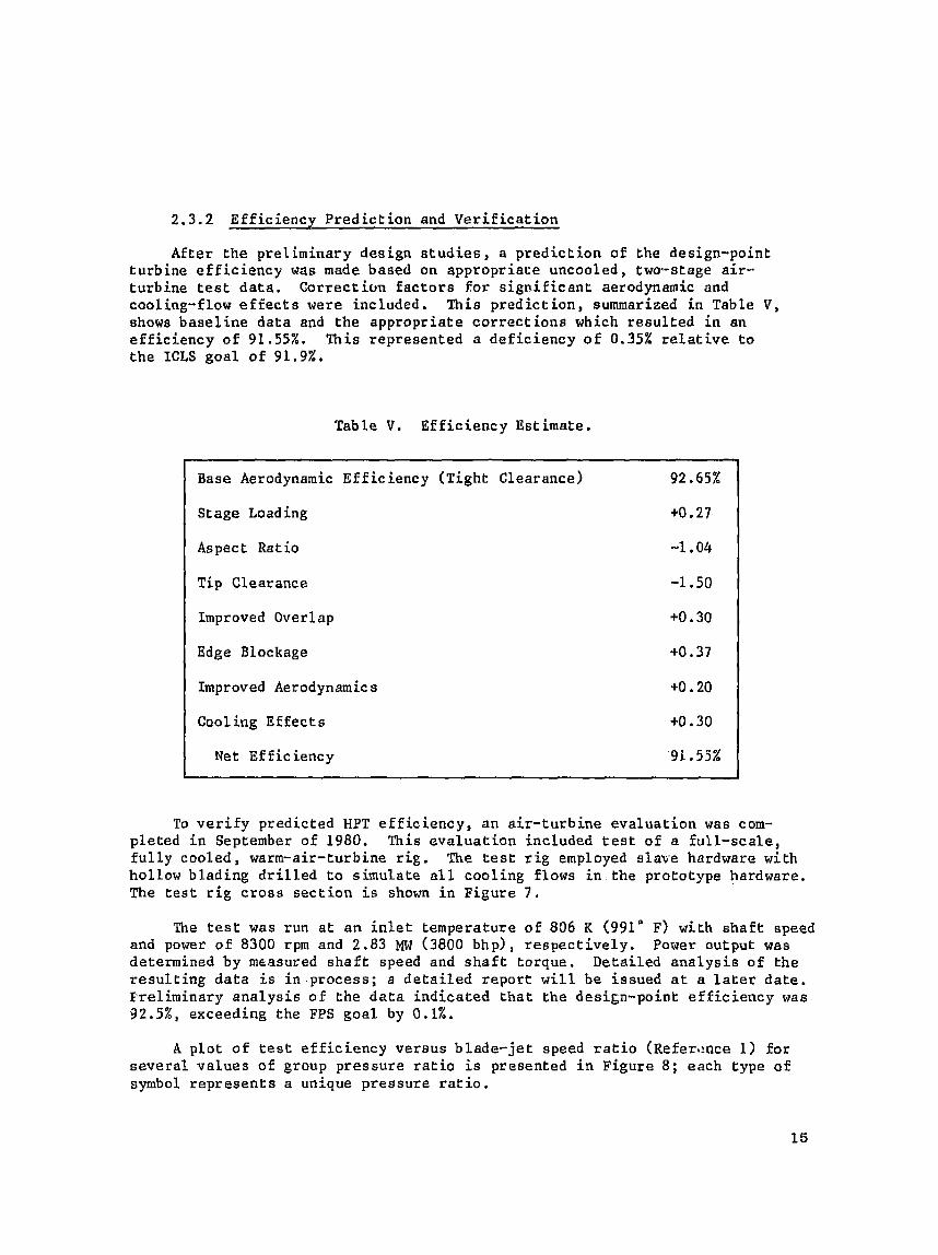
After t h e p r e l i m i n a r y design s t u d i e s , a p r e d i c t i o n of the design-point t u r b i n e e f f i c i e n c y was made based on appropriate uncooled, two-stage a i r - turbine t es t da ta . Correction factors f o r s i g n i f i c a n t aerodynamic and cooling-flow effects were included. Th is p r e d i c t i o n , summarized i n Table V , shows baseline d a t a and t h e a p p r o p r i a t e c o r r e c t i o n s which r e s u l t e d i n an ef f ic iency of 9 1 . 5 5 % . This r e p r e s e n t e d a d e f i c i e n c y of 0.35% re la t ive to t h e ICLS g o a l of 91.9%.
Tab le V . E f f i c i e n c y Est imate .
Base Aerodynamic E f f i c i e n c y ( T i g h t Clearance) 92.65%
S t age Load ing +0.27
Aspect Ratio -1.04
T i p Clearance -1.50
Improved Overlap 4 . 3 0
Edge Blockage +O -37
Improved Aerodynamics +O .20
Coaling Ef fec t s to. 30
Net Ef Eic ienc y ' 9 1 . 55%
To v e r i f y p r e d i c t e d HPT efficiency, a n a i r - t u rb ine evaluation was com- p l e t e d i n September of 1980. This e v a l u a t i o n included t e s t of a f u l l - s c a l e , f u l l y coo led , warm-air-turbine r i g . The t e s t rig employed s l a v e hardware wi th hollow b l a d i n g d r i l l e d t o simulate all c o o l i n g flows in the pro to type hardware. The t e s t r i g cross section i s shown i n F i g u r e 7 .
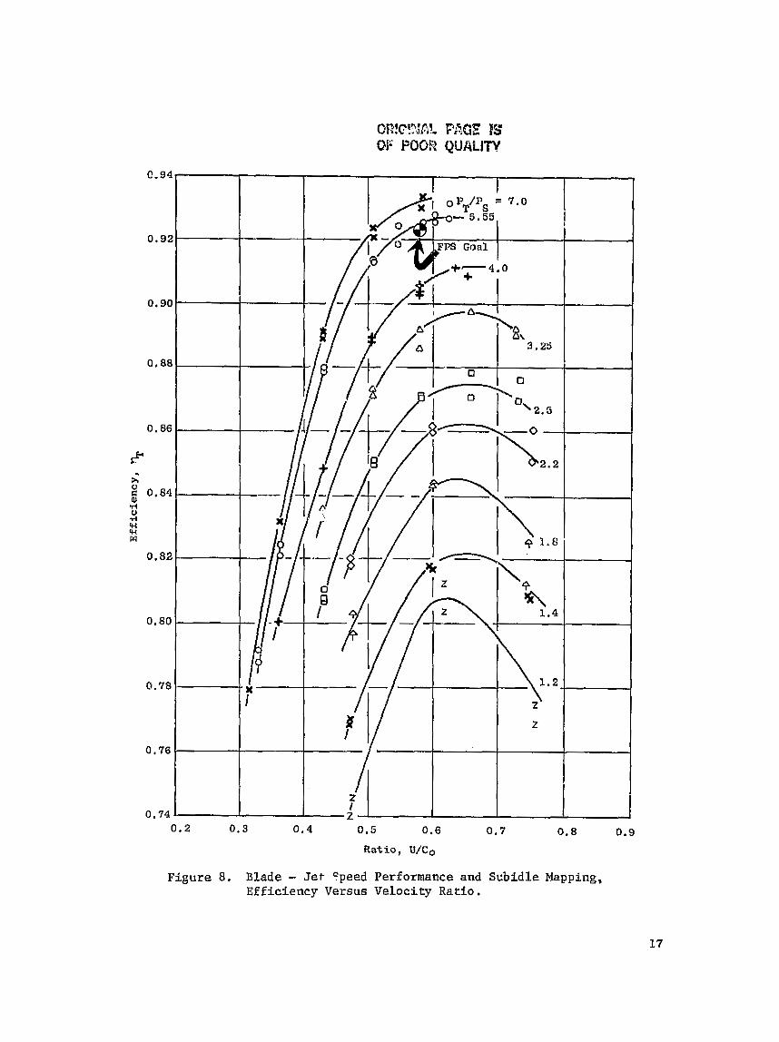
The test was r u n a t a n i n l e t temperature o f 836 K (991" F) with s h a f t speed and power of 8300 rpm and 2.83 MW (3800 bhp), r e s p e c t i v e l y . Power output was determined by measured s h a f t speed and s h a f t torque. D e t a i l e d a n a l y s i s of the r e s u l t i n g d a t a i s i n . p r o c e s s ; a d e t a i l e d r e p o r t will be i s s u e d a t a l a t e r d a t e . E'rel iminary a n a l y s i s o f t h e d a t a i n d i c a t e d t h a t the design-point e f f i c i e n c y was 92.5%, exceeding the FPS g o a l by 0.1%.
A p l o t of t e s t efficiency v e r s u s b l a d e - j e t speed r a t i o ( ~ e f e r e n c e 1) for several v a l u e s of group pressure r a t i o i s presented i n F igure 8; each type o f oymbol r e p r e s e n t s a un ique pressure ratio.

0.2 0.3 0 . 4 0.5 0.6 0.7 0 .8 0.9
Ratio, U/Co
Figure 8 , Blade - Jet- Speed Performance and S c b i d l e Mapping, Efficiency Versus Velocity Ratio.
3.0 COOLINt SYSTEM DESIGE: --
3 . 1 FEATUZF S AND DEVELOPbENT
3.1.1 General Descr ip t ion
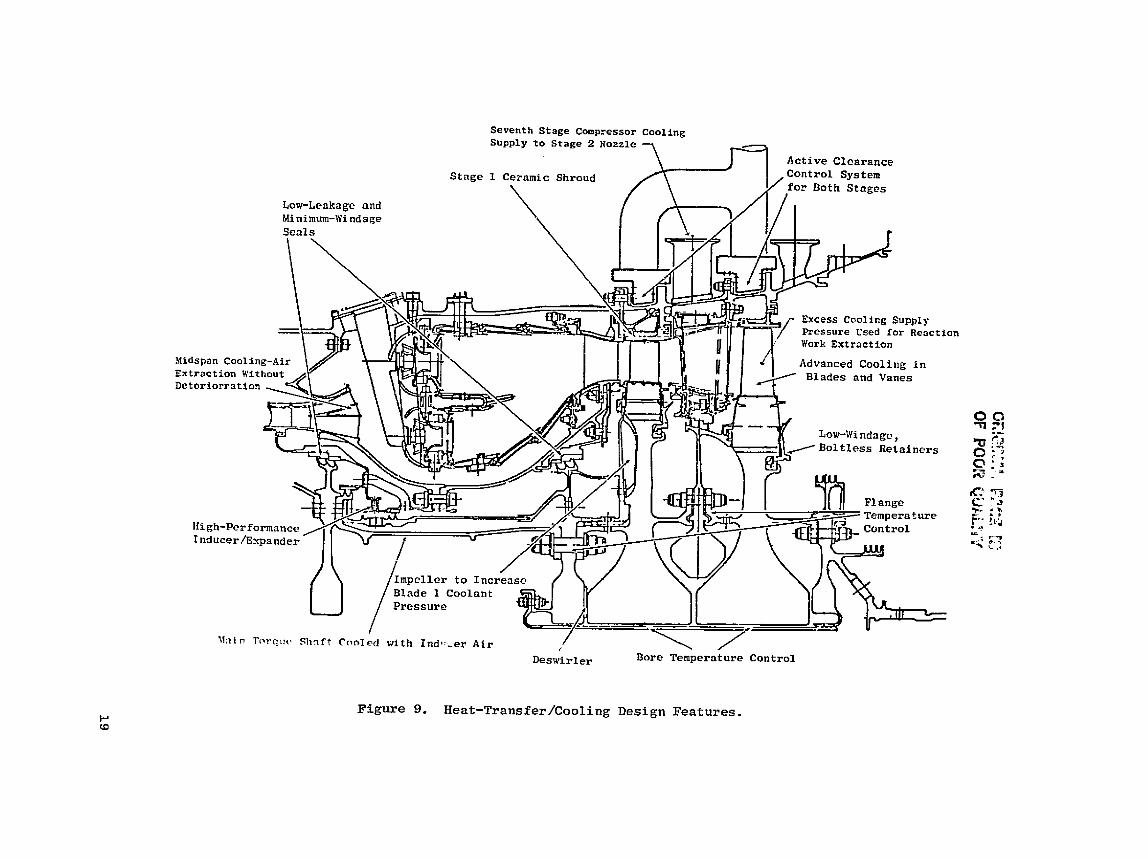
The E~ high presslire t u rb ine presents t h e cha l lenge of designing com- ponents t h a t maintain the l i f e ob jec t ives while achieving l e v e l s of o v e r a l l thermodynamic e f f i c i ency h igher than s ta te -of - the-ar t tu rb ines . The design of the W T cool ing system i s instrumental i n achieving these goa ls . Several o f the hea t - t r ans fe r and cool ing system f e a t u r e s a r e shown i n Figure 9.
The cool ing systems se l ec t ed f o r the hot-flawpath cmponents ( a i r f o i l s and end wal l s ) a r e high-cooling-efficiency designs; Lhus the des i red metal temperatures a r e achieved with low coolant-flow r a t e s . The low coolant-flow r a t e s lead d i r e c t l y t o high thermodynamic e f f i c i e n c y a s long a s the coolant i s returned t o the flowpath without causing l a rge mixing l oc ses .
In Stage I , where a r e l a t i v e l y h igh l e v e l of cool ing e f f ec t iveness i s requi red , i t i s necessary t o u t i l i z e the f u l l p o t e n t i a l o f the coolant i n o rde r t o main ta in low coolant-flow rates. The des ign chosen f o r the E~ uses the coolant f o r three separa te cooling mechanisms i n s e r i e s . F i r s t , t h e a i r convect ively coo l s the back s i d e of the Elowpath and a i r f o i l wal l s by imping- i ng on o r by flowing through small passages conta in ing turbulence promoters. The a i r then e n t e r s film holes and convcct ively coo l s t he wa l l s a s i t passes through. F i n a l l y , the a i r d i scharges from the ho le s onto the outs ide a i r f o i l sur faces and provides f i lm pro tec t ion from t h e h o t gas.
For t h e Stage 1 cooling system des ign , where a low-sol id i ty vane i s used, emphasis has been placed on reducing the amount: o f coolan t required and a l s o on in j ec t ing t h e coolant i n a manner t h a t minimizes performance pena l t i e s . The r a d i a l l y or ien ted ho le s are located i n reg ions o f very Low v e l o c i t y (lead- ing edges and pressure sur faces) where the r e s u l t i n g performance penal ty i s s l i g h t . Axial ly or iented ho le s , that: c o n t r i b u t e momentum t o the mixture, a r e used i n the h igher v e l o c i t y regions ( suc t ion su r f aces and t r a i l i n g edges) where they have been shown t o g ive exce l l en t f i lm p r s t e c t i o n i n add i t i on to lower mixing lo s ses .
In Stage 2 , where the required a i r f o i l cool ing-ef fec t iveness l e v e l s are lower, convec~ion-cool ing systems were chosen because of severa l important f a c t o r s . The use of convect ion/f i lm systems, as i n Stage 1, would theore t i - cally allow lower c o ~ l a n t flow r a t e s ; however, f i lm holes s ized f o r discharge of the low Stage 2 coolant flow r a t e s would e i t h e r be too f a r apar t t o g ive uniform cool ing o r be too small i n diameter . Small-diameter f i lm holes tend t o be more expensive to manufacture, a r e more prone t o plugging, and lead t o h igher e f f e c t i v e stresses. In addi t ion , a c e r t a i n quan t i t y of the Stage 2 nozzle coolant is u t i l i z e d f o r t i p d ischarge , t ra i l ing-edge d ischarge , and in t e r s t age - sea l blockage; when these q u a n t i t i e s a r e expended, very l i t t l e of t he cooling a i r remains f o r f i lm cool ing.
As part o f the turb ine cool ing system design, i t was imperative t h a t t he method of i n j e c t i n g the cooling a i r i n t o the gas stream be improved. The mag- nitude of the film-mixing lo s ses i s determined by the amount of coolant injec- t i o n , t h e coolant-to-gas v e l o c i t y r a t i o , the angle of i n j e c t i o n , and t h e l o c a t i o n o f i n j e c t i o n . A concerted e f f o r t has been made i n the ~3 program t o reduce the mixing losses of the film-cooling systems while accommodating t h e c o n s t r a i n t s imposed by manufacturing, t he convective systems, and the need f o r film protec t ion .
An upstream compressor-bleed l o c a t i o n was chosen t o supply cooling a i r t o t he Stage 2 t u r b i n e s t a t o r while s a t i s f y i n g backflow c r i t e r i a . Use of t h e lower pressure a i r f o r coolant improves thermodynamic e f f i c i ency because l e s s s h a f t work has be2n u t i l i z e d i n compression, and a smaller q u a a i t y of t he 1 ower temperature coolant is requi red .
A cooling-air expander, shown i n Figure 9 , i s u t i l i z e d t o acce l e ra t e the rotor-blade coolant i n the d i r e c t i o n of r o t a t i o n a t the l oca t ion where the coulant e n t e r s the r o t o r . This feaCure reduces the power required t o pump the coolant t o the blades and lowers the assoc ia ted temperature r i s e , The r e s u l t i s lower blade-coolant temperature and, t hus , lower coolant-flow r a t e . The rotor-coolant source i s conpressor-discharge air ext rac ted a t t he mean l i n e o f t h e combustor d i f f u s e r . The ob jec t ive of t h i s scheme, a s opposed t o ex t r ac t ing cool ing air E r o m ehe cornpresaor end wa l l , i s t o obta in lower temperature cool- ing a i r and t o lower the d e t e r i o r a t i o n r a t e . The cool ing-air expander pressure r a t i o i s chosen t o be cons i s t en t with the blade-coolant pressure required t o s a t i s f y the Stage 1 blade leading-edge backflow c r i t e r i a u t i l i z i n g a i r a t com- pressor d ischarge pressure. The cooling-air expander acce l e ra t e s t he a i r t o t h e wheel speed such t h a t t he roeor does not have t o do any pump work t o the a i r as i t is brought on board.
The reduced power required t o pump the coolant corresponds t o the s h a f t work t h a t would be saved i f the coolant were ex t rac ted Erom an upstream corn- pressor s t age a t the required coolant pressure. However, t h e upstream-extrac- r i o n system would be l e s s e f f i c i e n t due t o the low energy o f the end-wall b leed compared t o the diffuner-mean-line bleed se l ec t ed .
In each c a v i t y between Lhe r o t o r and s t a t o r , a n e f f o r t was made t o keep t h e windage drag a t a low l e v e l , Bolt covers were used where needed, and c a v i t y s i z e s were reduced whure poss ib le . A t any point where purge a i r was injected i n t o a c a v i t y , i t wa,a or ien ted i n the d i r e c t i o n of the r o t o r r o t a t i o n through t angen t i a l holes o r slots. This e f f o r t was d i r ec t ed a t keeping the a i r t angen t i a l v e l o c i t y a s c l o s e as possible t o the wheel speed i n order t o reduce drag on the r o t o r .
The number of s e a l t e e t h was optimized a t a l l l oca t ions i n the tu rb ine t o y i e l d the lowest performance c a s t . The performance ga ins due t o seal-leakage reduct ion assoc ia ted with more seal t e e t h were traded o f f against: the perfor- mance l o s se s assoc ia ted with the higher windage-power requirements induced by more sea l teeth.
ORIGINAL PAGE ES DE POOF? QUALITY
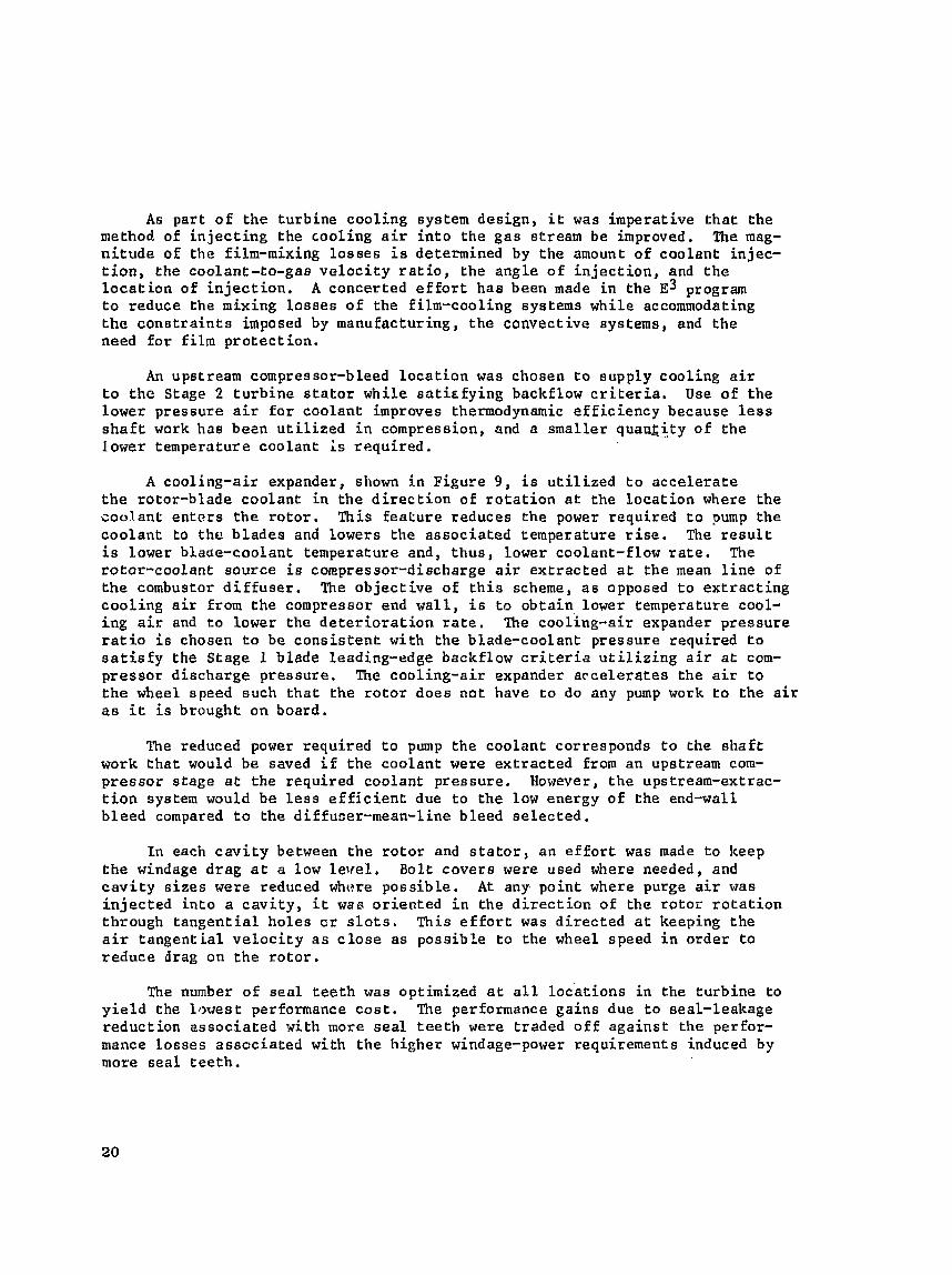
3.1.2 Trade S t u d i e s and Heat T r a n s f e r -- A s mentioned e a r l i e r i n t h e aerodynamic s e c t i o n , several t r a d e s t u d i e s
were conduceed t o a s s u r e the b e s t turbine-system performance. These s t u d i e s included a e r o t h e r m o d y n a i c design, h e a t t r a n s f e r , mechanical des ign , and manu- f a c t u r i n g c o n s i d e r a t i o n s .
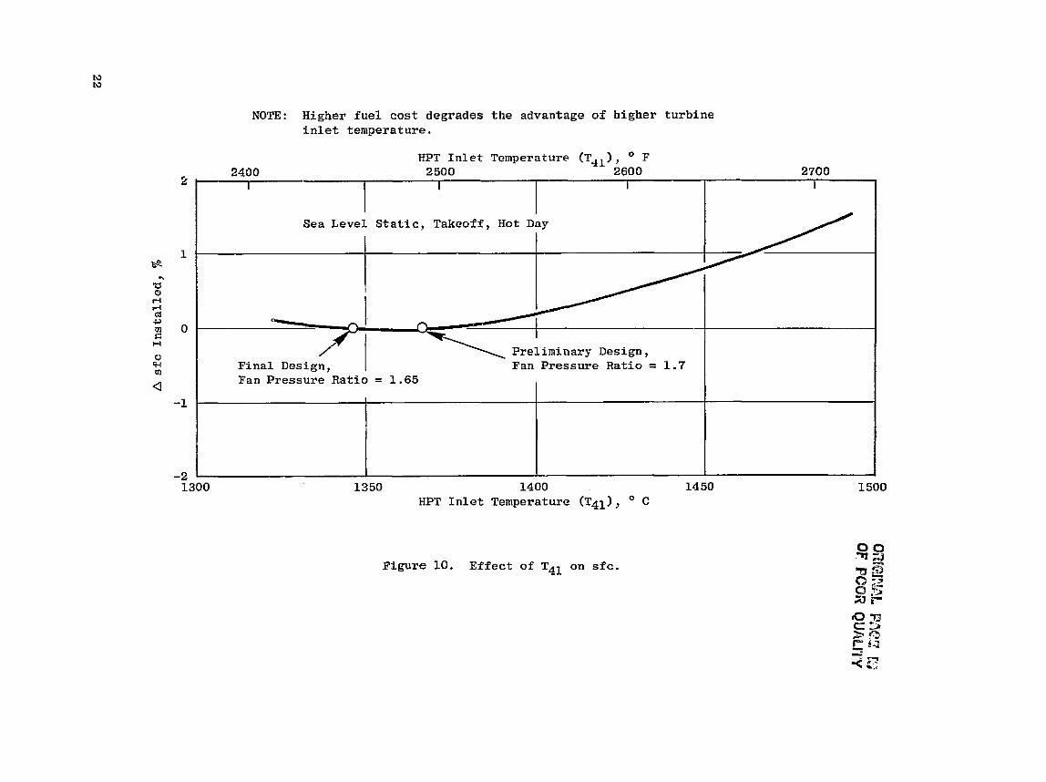
E a r l y i n t h e d e s i g n , t h e optimun t u r b i n e - i n l e t t empera tu re was s e t . The r e s u l t s of t h i s t r a d e s tudy, p r e s e n t e d i n F i g u r e 10, show t h e optimum, maximum t a k e o f f , t u r b i n e - i n l e t temperature t o be 1365" C (2490 F). To accommodate eng ine- th rue t growth p o t e n t i a l , t h e d e s i g n t u r b i n e - i n l e t temperature was s e t on t h e low s i d e o f t h e optimum a t 1343" C (2450" F). During th i s a n a l y s i s , t h e tu rb ine cooling-flow requ i rements and t h e eng ine c o r e s i z e were redefined for each t u r b i n e - i n l e t temperature under c o n s i d e r a t i o n .
With the optimum t u r b i n e i n l e t t empera tu re a t maximum takeoff d e f i n e d a t 1343" C (2450" F), t h e margin was d e f i n e d a t 78' C (140" F). The breakdown on t he HPT in le t - t empera tu re margin i s p resen ted i n Table VT.
Table VI. T4.1 Margin D e f i n i t i o n .
a
Direct Adders to Average Engine
Mfnimum to Average Engine a t Power Sett ing
Engine Trans ien t a t Takeoff Power Set r i n g
Open Clearance Schedule a t Takeoff
T o t a l D i r e c t Adders (DA)
20 Events V a r i a t i o n f
Humidity
Engine Qua1 i t y Variat ions
Cont ro i System Tole rance ( ~ n c l u d e s Tqg Measurement Tolerance)
Total Root Sum Square (RSS) Adders
To ta l Adders Required on New Engine (DA + RSS)
Added f o r Engine D e t e r i o r a t i o n - b *
Total Adder w i t h D e t e r i o r a t i o n AT41 = *
A T41 " C
7.2
16.7
11.1
35.0
3 . 8
14.4
13.8 - 20.5
5 5 . 5
22.2
77.7
" F
13
3 0
2 0 - 6 3
7
26
25 - 37
LOO
40
+I40
For the E~ t u r b i n e , t h e 22" C (40 " F) rnarg'n s p e c i f i e d f o r enpine d e t e r i - o r a t i o n i s somewhat below t h a t e s t a b l i s h e d from commercial eng ine-de te r io ra - t i o n exper ience . The r e d u c t i o n i n d e t e r i o r a t i o n should be r e a l i z e d due t o t h e new Active Clearance Control (Acc) system i n t h e compressor, HPT, and LPT a l o n g with improvements i n c o r e e n g i n e compressor b l a d e e r o s i o n , t h e power- management system, and t h e p r e d i f f u s e r midstream-bleed system for r o t o r c o o l i n g .
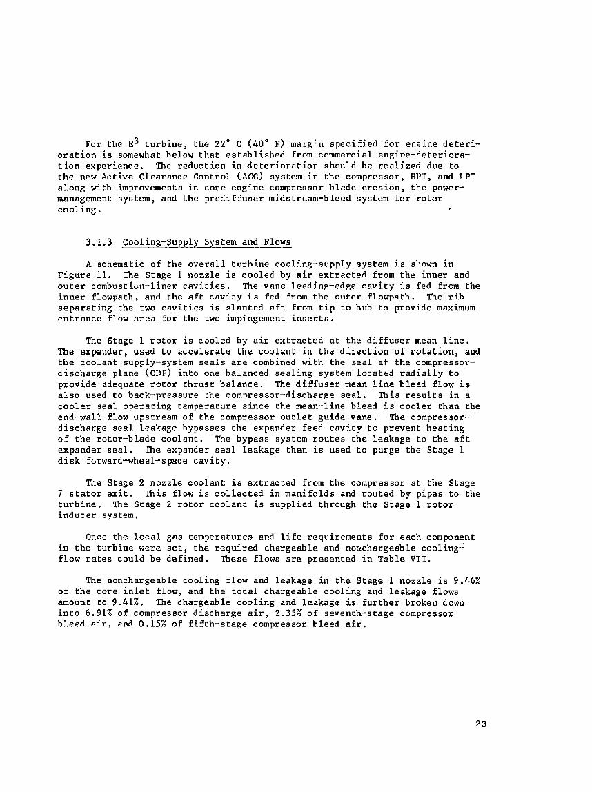
3 . 1 . 3 Cooling-Supply System and Flows
A schematic of the o ~ e r a l l t u r b i n e cooling-supply syseem i s shown i n F i g u r e 11. The S tage 1 nozz le i s coo led by a i r e x t r a c t e d from t h e inner and o u t e r combust iur~- l iner c a v i t i e s . The vane leading-edge c a v i t y i s fed from t h e i n n e r f lowpath, and t h e a f t c a v i t y i s fed from t h e o u t e r f lowpath, The r i b s e p a r a t i n g t h e two c a v i t i e s i s s l a n t e d a f t from t i p t o hub t o p rov ide maximum e n t r a n c e flow a r e a fo r the two impingement i n s e r t s .
The Stage 1 r o t o r i s cso led by a i r e x t r a c t e d a t t h e d i f f u s e r mean l i n e . The expander, used t o a c c e l e r a t e t h e c o o l a n t i n t h e d i r e c t i o n o f r o t a t i o n , and t h e coo lan t supply-system s e a l s a r e combined wi th t h e s e a l a t t h e compressor- d i s c h a r g e p lane (CDP) i n t o one balanced s e a l i n g system l o c a t e d r a d i a l l y t o p rov ide adequate r o t o r t h r u s t b a l a n c e . The d i f f u s e r mean-line b leed f low i s a l s o used t o back-pressure the compressor-discharge s e a l . Th i s r e s u l t s i n a c o o l e r seal o p e r a t i n g temperature s i n c e the mean-line b leed i s c o o l e r t h a n t h e end-wall f low upst ream of t h e compressor o u t l e t g u i d e vane. The compressor- d i s c h a r g e s e a l l eakage bypasses t h e expander feed c a v i t y t o prevent h e a t i n g o f t h e rotor-blade c o o l a n t . The bypass system r o u t e s t h e l eakage t o t h e a f t expander s e a l . The expander s e a l l eakage then i s used t o purge the S tage 1 d i s k fcrward-wheel-space c a v i t y .
The Stage 2 nozz le c o o l a n t i s e x t r a c t e d from t h e compressor a t the Stage 7 s t a t o r e x i t . This f low i s c o l l e c t e d i n mani fo lds and r o u t e d by p ipes t o t h e t u r b i n e . The S tage 2 r o t o r c o o l a n t i s supp l ied through t h e Stage 1 r o t o r i n d u c e r sys tern.
Once t h e l o c a l gas temperatures and l i f e requ i rements fo r each component i n t h e t u r b i n e were set , t h e r e q u i r e d chargeab le and nonchargeable cooling- f low r a t e s cou ld be d e f i n e d . These f lows a r e p resen ted i n Tab le V L L .
The nonchargeable coo l ing f low and leakage i n the S tage 1 nozz le i s 9.46% o f t h e core i n l e t f low, and t h e t o t a l chargeab le coo l ing and leakage f lows amount t o 9.41%. The chargeable c o o l i n g and l eakage i s f u r t h e r broken down i n t o 6.91% of compressor d i s c h a r g e a i r , 2.35% of seventh-s tage compressor b l e e d a i r , and 0.15% of f i f t h - s t a g e compressor b leed a i r .
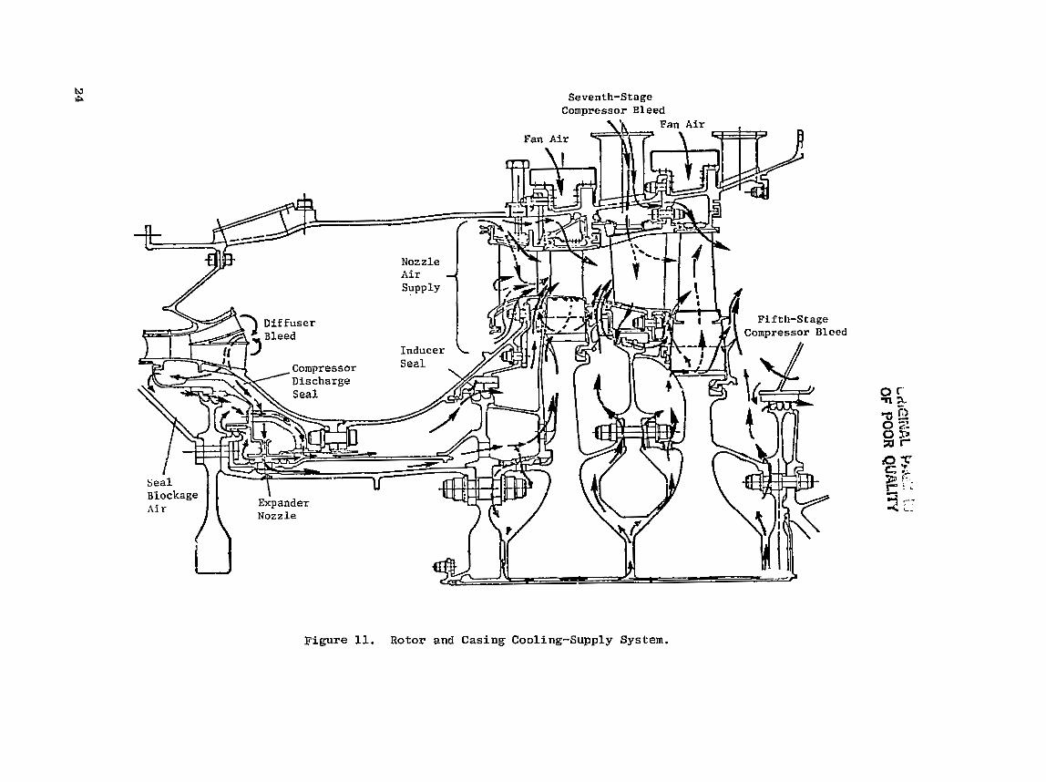
Figure 11. Rotor and Casing Cooling-Supply System.
Table VII . Cooling and Leakage Flows.
3.1.4 F l i g h t Mission
a c o n s t a n t - ~ i f e / ~ i x e d Engine
a Max C l i m b , 10.67 km (35,000 f e e t )
I n o r d e r t o p roper ly d e f i n e t h e h e a r - t r a n s f e r d e s i g n o f each component i n the t u r b i n e , i t i s necessa ry t o d e f i n e an ap ropcia te a i r c r a f t l e n g i n e S miss ion . The mission that was chosen f o r t h e E was a 2-hour f l i g h t t y p i c a l o f a domestic commuter a i r l i n e . Th i s m i s s i o n i s presented i n F i g u r e 12. Lr should be noted t h a t each component h a s i t s own worst mission, In doing t h e t u rb ine h e a t - t r a n s f e r a n a l y s i s , va r i a t ions to t h e mission were considered for each component. The complete m i s s i o n , i n c l u d i n g s t a r t and shutdown, had t o be analyzed for the r o t o r s t r u c t u r e whi le t h e i d l e , takeoff, and t h r u s t - reverse m i s s i o n s were analyzed f o r t h e b l a d e s and vanes. The gas- temperature p r o f i l e s associated with t h e double-annular-combus t o r f u e l schedule dur ing s t a r t i n g were eva lua ted f o r the b l a d e s and vanes.
Flow
Nonchargeable Cooling and Leakage
CDP Leakage and Purge A i r S t a g e 1 Shroud (CDP) Stage 1 Blade (CDP 1nd)
Stage 2 Vane and I n t e r s t a g e Seal Blockage A i r (compressor Stage 7 )
Stage 2 Shrogd (compressor S tage 7 ) Wage 2 Blade (CDP I n d )
Disk 2 AfL-Cavity Purge Air (Compressor S tage 5 ) To t a l
The mission mix e v a l u a t e d d a t a f o r sea l eve l h o t day 500C (122OF), f l a t r a t i n g day 30% ( 8 6 O ~ ) , s t a n d a r d day 150C ( 5 g 0 ~ ) , and co ld day -20C (290) take- off c o n d i t i o n s . The eng ine t h r u s t i s constant (flat rated) up t o t h e corner p o i n t t empera tu re and then i s l i m i t e d by a constant t u rb ine r o t o r i n l e t tempera- ture of 13430C (24SOoF). A t t h e hot day tempera tu re , the t u r b i n e w i l l run a t tI,e same temperature as t h e c o r n e r p o i n t bu t a t a lower p r e s s u r e . A comparison of the significant hear t r a n s f e r pa ramete rs f o r t h e ho t day and c o r n e r point day i s shown in T a b l e VIII.
%W25
9.46 2.25
0.6
3.3 2.0
0.35
0.76 0.15 18.87

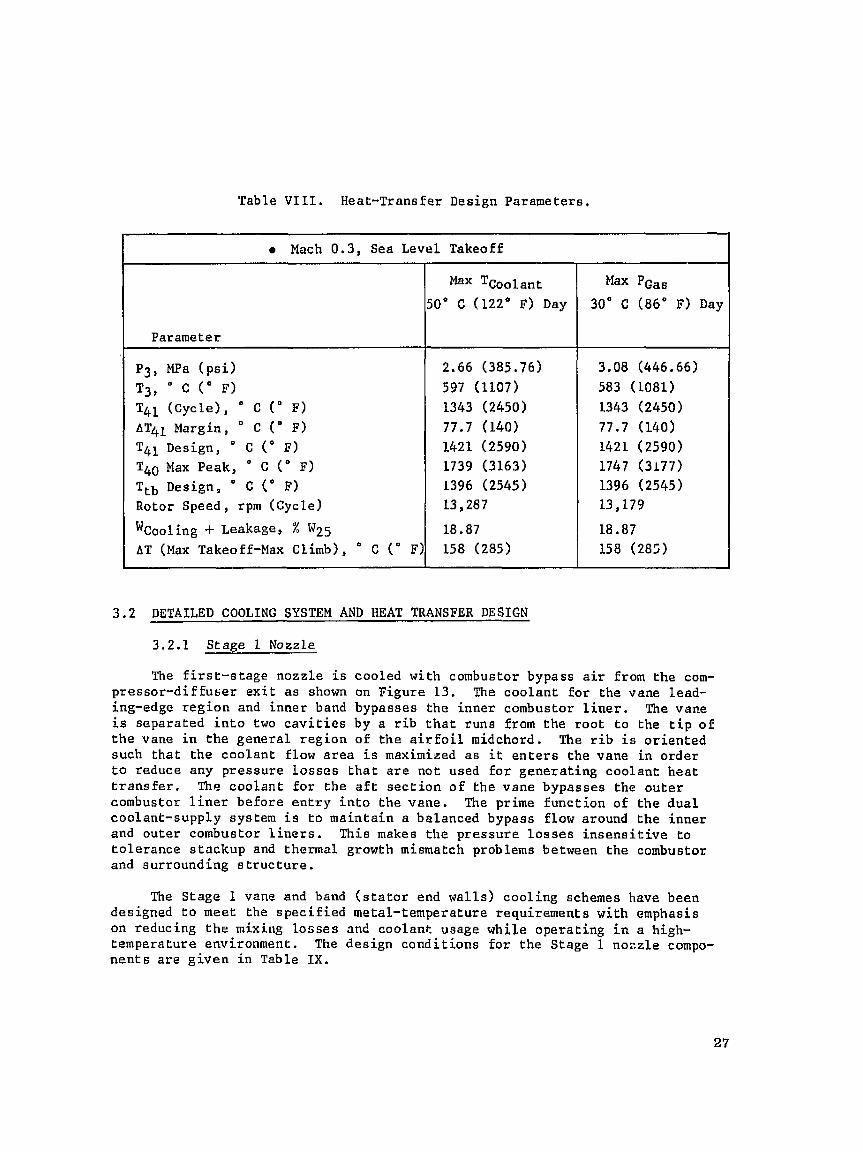
Table V I I L . Heat-Transfer Design Parameters.
DETAILED COOLING SYSTEM AND HEAT TRANSFER DESIGN
Mach 0.3, Sea Level Takeoff
3.2.1 Stage 1 Nozzle
Parameter
Pg, MPa ( p s i )
Tg, a C ( " F) T4l ( c y c l e ) , " C ( " F)
AT41 Margin, " C ( " F) T41 Design, ' C ( O I ? )
TbO Max Peak, O C ( O F) Ttb Design, ' C (" F) Rotor Speed, rpm (cycle)
Wcooling -t ~ e a k a g e , % W25 AT ax Takeoff-Max ~ l i m b 5 , " C (" F)
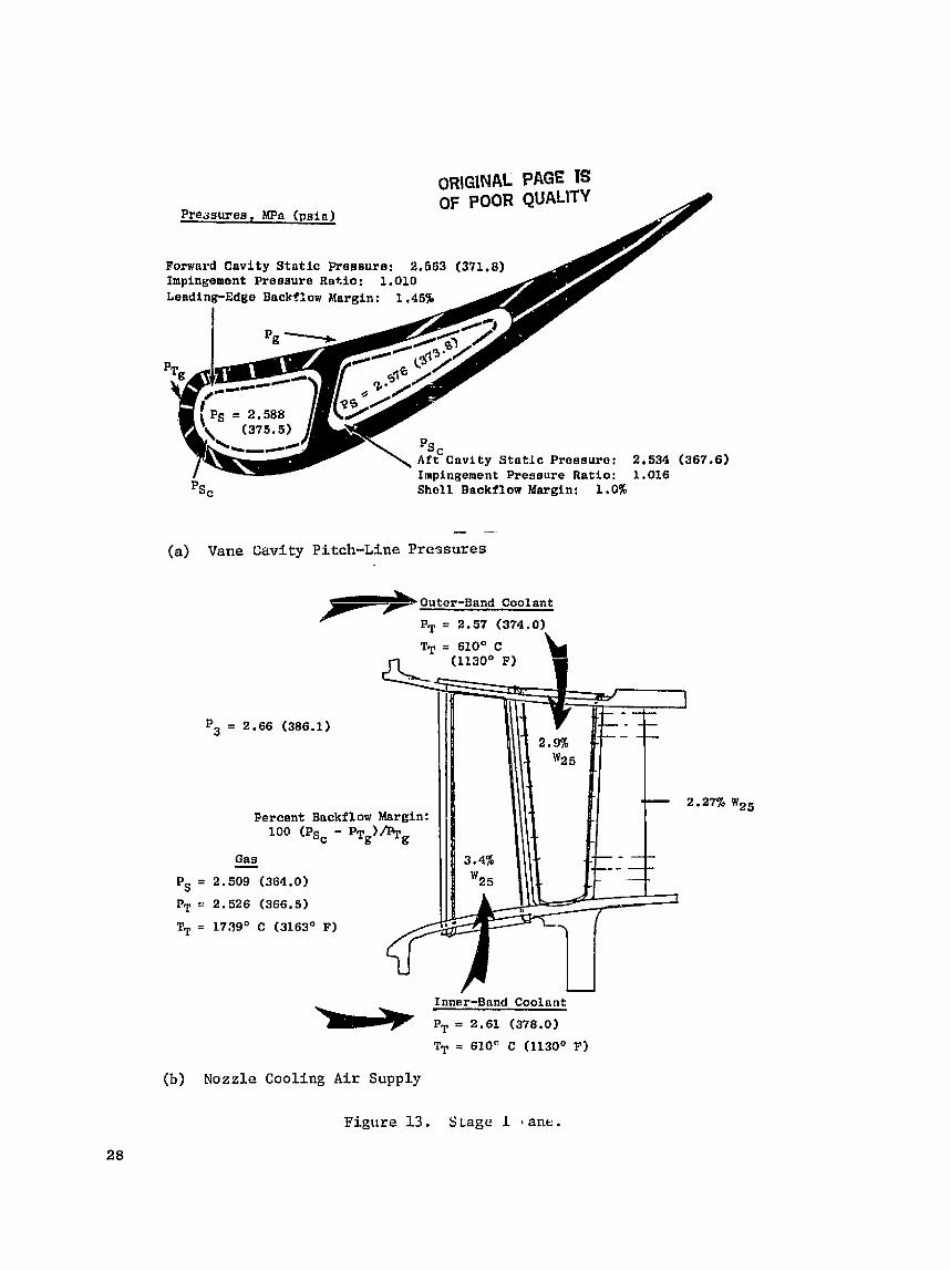
The f i r s t - s t a g e nozzle i s cooled with combustor bypass a i r from the com- pressor -d i f fuser e x i t as shown on Figure 13. The coolant f o r the vane lead- ing-edge reg ion and inner band bypasses the inner combustor l i n e r . The vane i s separated i n t o two c a v i r i e s by a r i b t h a t rune from the root t o the t i p o f t h e vane i n t he general reg ion of the a i r f o i l midchord. The r i b i s o r ien ted such tha t the coolant flow a rea i s maximized a s i t e n t e r s the vane i n order t o reduce any pressure Losses t h a t a r e not used f o r generat ing coolant h s a t transfer. The coolant f o r the a f t s ec t ion o f the vane bypasses the outer combustor l i n e r before e n t r y i n t o the vene. The prime funct ion of the dual coolant-supply system i s t o maintain a balanced bypass flow around the inner and outer combustor l i n e r s . This makes t he pressure l o s s e s i n s e n s i t i v e to to le rance atackup and thermal growth mismatch problems between the combustor and surrounding s t r u c t u r e .
The Stage 1 vane and band ( s t a t o r end wal l s ) cool ing schemes have been designed t o meet the spec i f i ed metal-temperature requirements with emphasis on reducing t h e mixing Losses and coolant usage while operat ing i n a high- temperature environment. The design condi t ions f o r the Stage 1 nozzle compo- nen t s a r e g iven i n Table IX.
Max T ~ o o l a n t
SO0 C (122" F) Day
2.66 (385.76) 597 (1107) 1343 (2450)
77.7 (140) 1421 (2590) 1739 (3163) 1396 (2545) 13,287
18.87 158 (285)
Max P ~ a s 30" C (86' F) Day
3.08 (446.66)
583 (1081) 1343 (2450)
77.7 (140) 1421 (2590) 1747 (3177) 1396 (2545) 13,179
18.87
158 (285)
ORIGINAL PAGE IS OF POOR QUALITY
Pre~suree , MPn ( p s i n )
Impingement Pressure Ratio: 1.016
Psc Shell Backflow Margin: 1.0%
- - (a) Vane Cavity Pitch-Line Pressures
Outer-Band Coolant
PT = 2.57 (374.0)
p3 = 2.66 (386.1)
2 , Percent Bnckflow Margin: 100 (Ps, - PTg)
Gas - = 2.509 (364.0)
= 2.526 (366.5)
= 1739' C (3163' F)
Inner-Band Coolant
PT = 2 .61 (378.0)
U
(b) Nozzle Cooling Air Supply
Figure 13. Stage 1 1 ane.

Table I X . Stage 1 Vane Cooling Parameters .
Nonchargenb l e Plow, % W25 P a t t e r n FacLor
Tq.0 Max Peak, ' C ( O F )
T ~ o o l a n t * " c ( " P ) Leadidg-Edge Backflow Margin, %
WC Vanes, % W25 lJC Bands, % W25
WLealtage, % W25 (Nonchargeable)
W ~ ~ ~ k ~ ~ ~ r % W25 (chargeab le ) Number of Vanes
A d e t a i l e d schemat ic o f t h e c o o l i n g system f o r t h e Stage 1 vane i s shown i n F igure 13. This d e s i g n i n c l u d e s two impingement i n s e r t s and t r a i l i n g - e d g e , pressure-side-bleed (PSB) s l o t s . The c o o l i n g des ign makes e x t e n s i v e u s e of f i l m c o o l i n g and impingement coo l ing a t t h e vane l e a d i n g edge and t h e midpor- t i o n of t h e vane and e f f i c i e n t , convec t ive , long s l o t s i n t h e vane t r a i l i n g edge. The c o o l i n g a i r , drawn from t h e combustor l i n e r , i s fed from the s t a t o r inner Elowpath f o r t h e leading-edge i n s e r t and from t h e s t a t o r o u t e r f lowpath f o r the a f t i n s e r t . Th i s arrangement t a k e s advantage of t h e cornpressor-dis- charge t o t a l p r e s s u r e p r o f i l e t o p rov ide a h igher c o o l a n t feed p r e s s u r e a t the combustor i n n e r l i n e r and m a i n t a i n a p o s i L ~ v e p r e s s u r e r a t i o a c r o s s t h e lead- ing-edge f i l m h o l e s , a s shown i n F igure 13. I n a d d i t i o n , t h e r i b s e p a r a t i n g t h e two i n s e r t s i s s l a n t e d t o c f e a t e l a r g e r e n t r a n c e flow a r e a s f o r bo th i n s e r t s .
The two impingement i n s e r t s , shown i n Figure 14, have a p r e s c r i b e d pat- t e r n of smal l h o l e s c h a t provide h i g h l y e f f e c t i v e coolir lg by impinging cool- ing a i r normal t o t h e i n s i d e s u r f a c e of t h e vane s h e l l . The impingement-hole spacing v a r i e s between f o u r and e i g h t d iamete r s i n t h e leading-edge i n s e r t and between s i x and e i g h t d iamete r s on t h e a f t i n s e r t . Th i s impingement-hole p a t t e r n v a r i a t i o n i s used t o ba lance the temperature g r a d i e n t s between a high- h e a t - f l u x , low-film l o c a t i o n and t h e low-heat-flux, h igh-f i lm l o c a t i o n on t h e vane gas s i d e .
Considerable a t t e n t i o n was d i r e c t e d t o t h e c o o l i n g - a i r p r e s s u r e l o s s e s o f t h e o u t e r and i n n e r combustor l i n e r s . Because of t h e compressor p r e d i f f u s e r dump p r e s s u r e l o s s e s and t h e f u e l - n o z z l e / s k i r t b lockage, t h e o u t e r - l i n e r pres- s u r e l o s s e s were 3% a s i n d i c a t e d by t h e combustor model t e s t s . The inner-band p r e s s u r e l o s s e s were 2%. The t o t a l p r e s s u r e l o s s e s f o r t h e complete syscem amounted t o 3.15% a t Lhe o u t e r band anti 2.12% a t t h e i n n e r band. In o r d e r t o h e l p overcome the l a r g e r t h a n expected p r e s s u r e l o s s i n t h e combuskor o u t e r l i n e r , a bellmouth was des igned f o r t h e i n l e t t o t h e a f t i n s e r t , as shown i n F igure 14. Th is f e a t u r e reduced the veloci ty-head l o s s by 35% and h o l d s t h e a f t - i n s e r t impingement p r e s s u r e d r o p t o I%; t h i s i s comparable t o c h a t of t h e leading-edge i n s e r t . Vane-shell backflow margins o f 1% i n t h e a f t c a v i t y and 1.45% i n t h e forward c a v i t y r e s u l t e d .

DlBplcn, b Placca
0.071-ca (0.028-in. )
Irplngsaent Dafflo Dravhargo Pressurtn . 2.883 UPn (37I .H psi) Dianotcr Implngcmcnf Impin~elant Prer ruro flatlo u 1.01
Pr = 1.01 P = 2,5wn MPn (375.5 pub)
Four-Dl naotur Spucl nr: (Vuno Louding edge)
(a) Leading-Edge Impingement B a f f l e
Impin~cment Preaauro urnti, , 1.017
0.071-cm (0.028-in.) 1%-I)LnmuLcr Spoclnu (Pruseurc Sido)
P m 2.552 MPn (370.3 pel)
Eight-Uiemctcr Spaclng (Suctlc~n Sldc)
(b) A f t Impingement Baffle
Figure 14, Stage 1 Nozzle Impingement B a f f l e s .

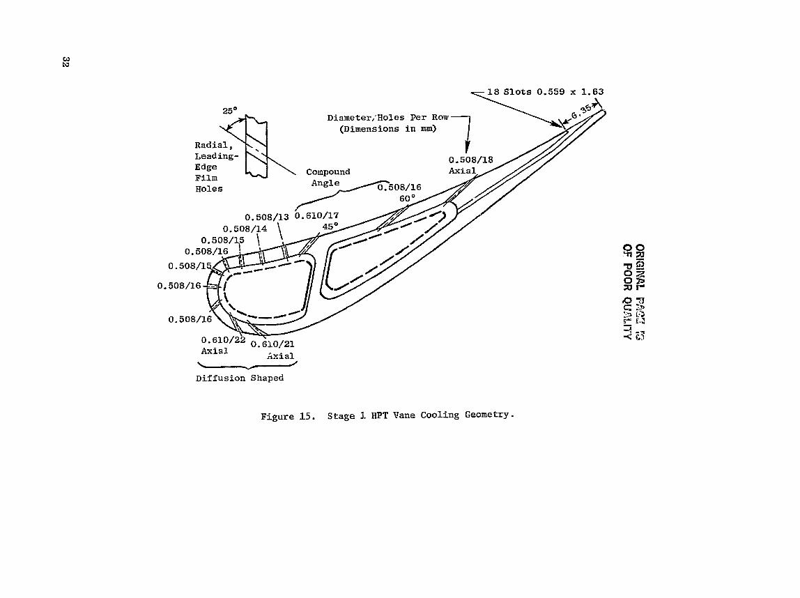
After t h e impingement, t h e coolant i s in jec ted i n t o the hot-gas stream for f i lm cool ing through va r ious types of f i lm holes d r i l l e d i n t h e vane sheL1. The film-hole p a t t e r n i s shown i n Figure 15.
The pressure-side-bleed s l o t s incorporated i n the cu r r en t vane design f o r cooling t h e t r a i l i n g edge o f f e r improved s t a t o r performance. The s l o t s discharge cool ing a i r t o a lower gas-side Mach number a r ea and r e s u l t i n a smaller coolant/mains tream mixing 10s s compared t o conventional , t r a i l ing-edge b leed .
!L%e vane i s designed f o r t he l o c a l maximum tu rb ine- in le t temperature of 1739" C (3163" F). The t o t a l cooling flow required i s 6.3% W25 of which 3.4% W25 i s f o r t h e forward i n s e r t and 2.9% W25 i s f o r t he a f t i n s e r t . The vane p i tch- l ine bu lk ma te r i a l temperature is 947" C (1737" F) with the l o c a l lead- ing and t ra i l ing-edge su r f ace temperatures under 1093" C (2000" F) i n t he hot s t r e a k . The thermal-node breakdown used i n the heat - t ransfer ana lys i s i s pre- sented i n F igure 16 and c o n s i s t s of 164 nodes and 63 sepa ra t e temperature and hea t - t r ans fe r c o e f f i c i e n t t a b l e s o f 35 time steps. Vane s teady-s ta te temper- a t u r e s a t hot-day takeoff a r e a l s o shown i n Figure 16. The hot-day takeoff t r a n s i e n t was a l s o analyzed s i n c e the t r a n s i e n t temperature g rad ien t s appear t o be the most l i f e l i m i t i n g . The t r a n s i e n t ana lys i s accounted f o r the com- bus to r f u e l schedule a t i d l e and t r a n s i e n t maximum takeof f .
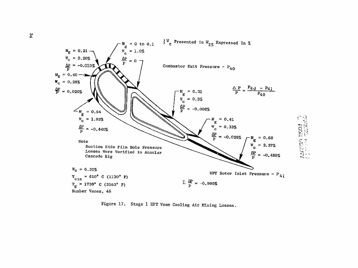
The momentum mixing l o s s e s assoc ia ted with f i lm i n j e c t i o n i n t o the gas stream were evaluated i n d e t a i l . This s tudy showed t h a t t he major l o s s e s occur ar t he pressure-side t r a i l i n g edge and a t the suct ion-side f i lm holes . Annular-cascade d a t a v e r i f i e d t h e l o s s e s from the suct ion-side f i lm ho le s , a s shown i n F igure 17, and ind ica ted a need t o decrease the to le rance i n the t ra i l ing-edge , pressure-side s l o t s . The annular-cascade hardware incorporated s l o t s with excess ive d i f f u s i o n . Even though they met t he flow-chezk require- ments, the v e l o c i t y of t he a i r leaving t h e s l o t s was low enough to double the mixing l o s s e s of the t rai l ing-edge flow, The to le rances on the s l a t s were subsequently reduced on both the a i r - t u rb ine r i g and t h e engine hardware.
The cool ing design f o r the s t a t o r inner band i s i l l u s t r a t e d i n Figure 18. The inner and the outer bands are both designed t o be cooled on the back s i d e by an a r ray o f coolant j e t s impinging from a b a f f l e p l a t e fed by a coolant plenum. The spent: impinging a i r i s then c o l l e c t e d and discharged from rows o f f i lm holes i nc l ined t o t he main gas flowpath t o c r e a t e a f i lm over the band h o t surface. With the emphasis on reducing t h e s t a t o r performace mixing-loss penal ty, a l l f i l m holes a r e s e l e c t i v e l y loca t ed upstreom o f t h e vane flowpath t h r o a t where the local gas Mach numbers a r e r e l a t i v e l y low, This cha rac t e r i s - t i c a l l y r e s u l t s i n lower coolant/gas-stream mixing lo s ses . The placement and o r i e n t a t i o n of t he f i lm holes a l s o take i n t o account end-wall, secondary-flow e f f e c t s on t h e f i lm.
The d e t a i l s o f the outer-band cooling system a r e presented i n Figure 1 9 . The outer band used a cool ing flow of 1.5% W25 and t h e inner-band cool ing design r e q u i r e s 1.3% W25. The band flowpath intersegment s e a l s a r e of t he hour-glass type from the band leading edge back t o the nozzle t h roa t ; spline
ORIGIIVWP PP,%
tS
O
F POOR Q
UA
LITY
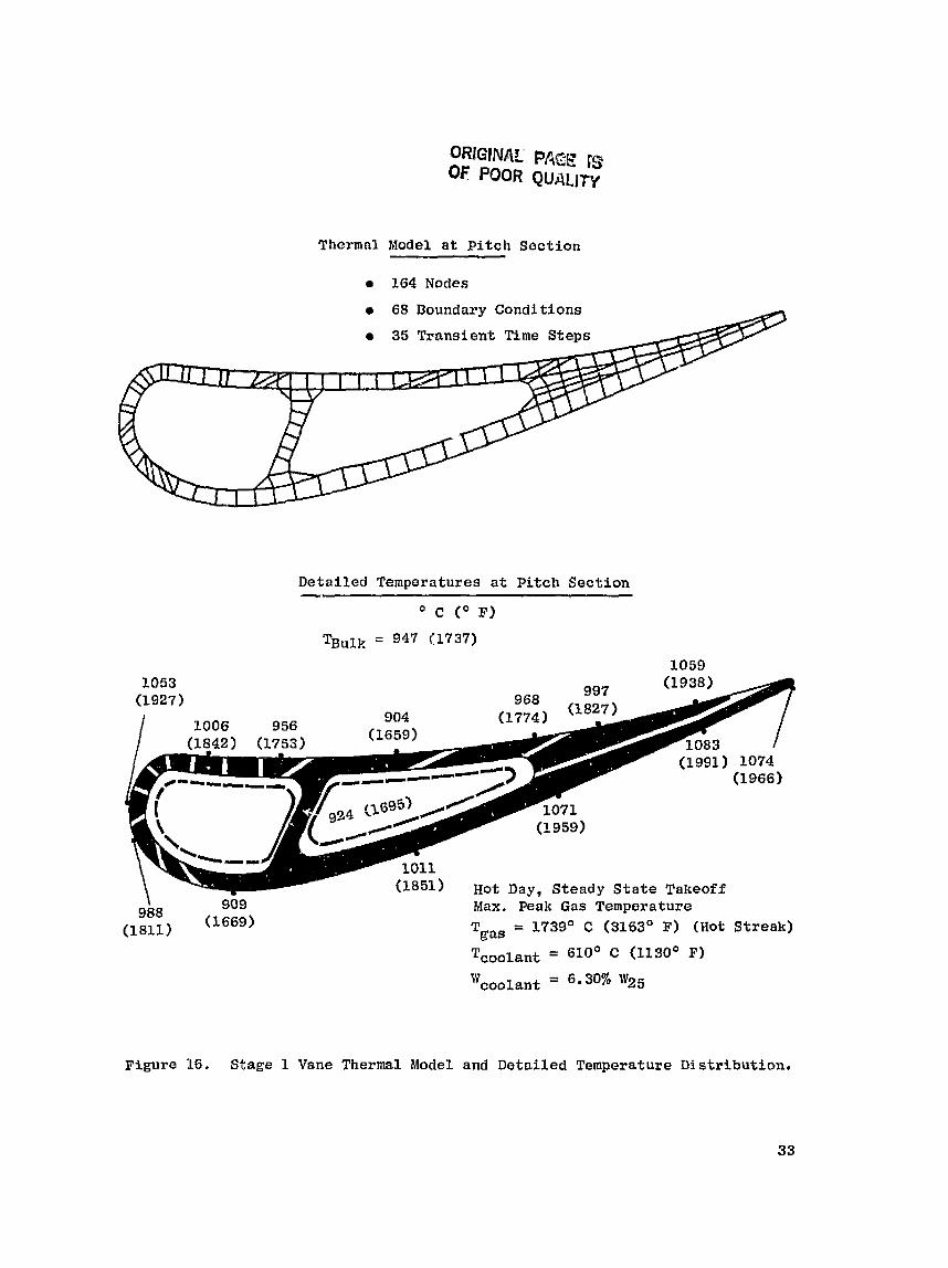
ORIGINAL PACE IS OF POOR QUALITY
Thermnl Model a t P i t c h Sectton
164 Nodes
68 Boundary Condit ions
a 35 Transient Time Steps
Detailed Temperatures at P i t c h Section
Max. Peak Gas Temperature Tgae = 3.739' C (3163O F ) (Hot Streak)
Toolant = 610" C (1130' F)
Wcoolant 8.30% W25
Figure 16. Stage 1 Vane Thermal Model and Detailed Temperature Distribution.

TGas Design
Impingement Plus Film Cooling r Inner Band - 1461" c Outer Band - 1556' C
T - 610" C oolant:
Cornpartmentized x
Cav i t i e s b
I F i l m Cooling Air Exit
Impingement Raised Land P l a t e Brazed
+ 1 Cornpartmentized
to Band Cooling Cavities
Impinges on Band -
Figure 18. Stage I Vane, Inner Bad.

E: M
*rl VJ ffl D
u
rd ffl E
sea l s a r e used from the t h r o a t back t o the t r a i l i n g edge, The f langes al.so incorporate s p l i n e s e a l s . The leakage through these s e a l arrangements r e s u l t s i n a t o t a l nozzle leakage flow of 0.67% W25.
3.2.2 Stage 1 Rotor
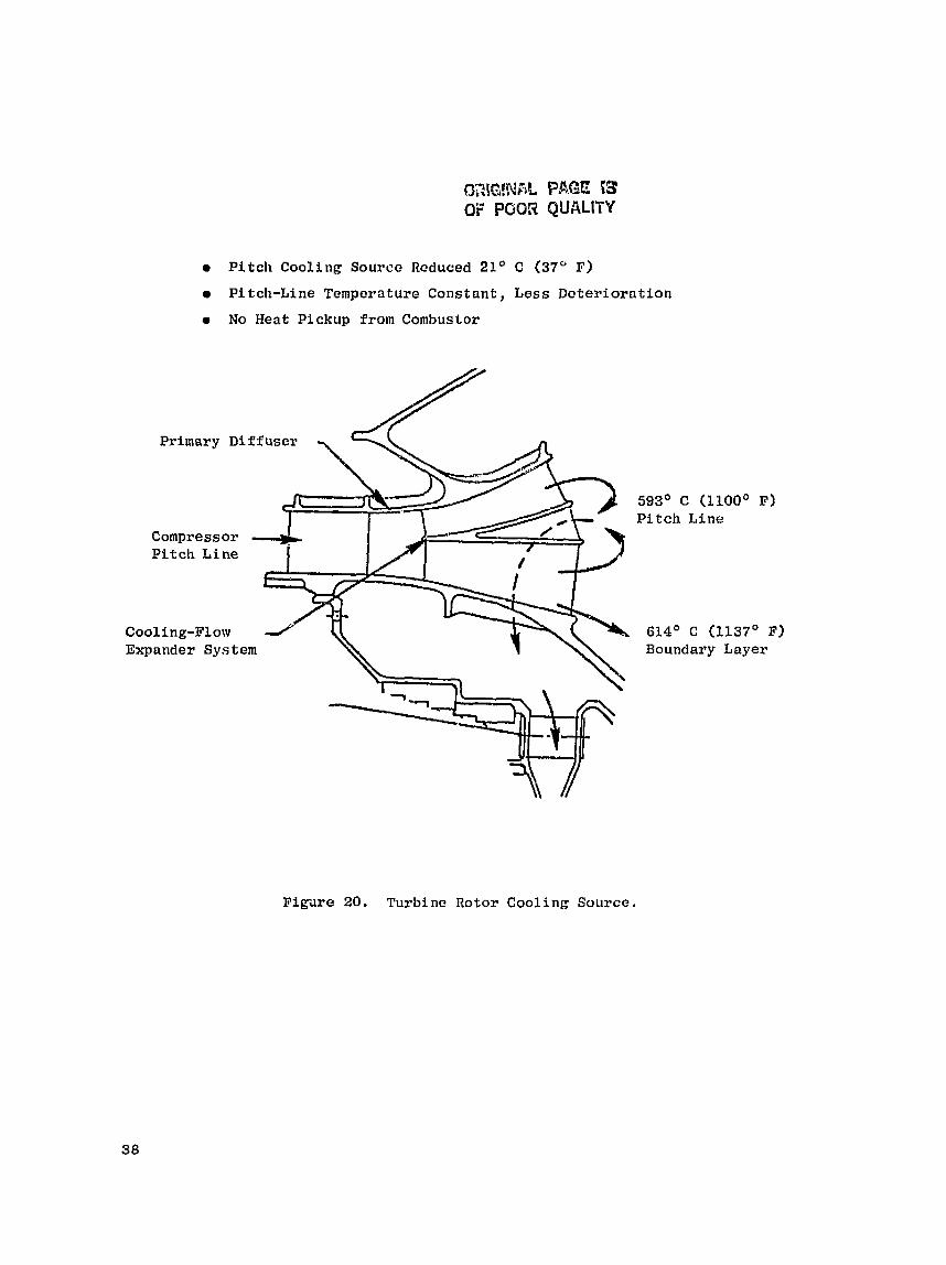
The design goal of the cooling-aj.r-supply system f o r the Stage 1 r o t o r i s to d e l i v e r coolant a t t he lowest poss ib le temperature a t the required design pressure . The high e f f i c i e n c y requirements of t h e E~ necess i ta ted the design of a cooling sys tem t h a t i s more e f f e c t i v e than cu r ren t , commercial designs. Stage 1 r o t o r coolant i s ex t rac ted from the compressor d i f f u s e r e x i t a t t he midspan, a s shown i n Figure 20. Relat ive t o e x i s t i n g systews, t h i s source y i e lds a cooler supply of a i r t o the r o t o r , This coo le r a i r (19 t o 22' C (35 t o 40' F)] al lows a reduct ion i n blade cool ing-air usage and r e s u l t s i n a d i r e c t engine-eff ic iency ga in . Midspan e x t r a c ~ i o n a l s o tends t o s t a b i l i z e the d i f f u s e r dump flow s ince the a i r i s ex t r ac t ed from the wake region of t he d i f f u s e r . As the engine d e t e r i o r a t e s due to t he compressor flowpath s e a l s opening up , t he midspan temperature w i l l be a f f ec t ed t h e l e a s t . In terms of d e ~ i g n s p e c i f i c s , t he ex t rac ted r o t o r cool ing a i r i s 6% of the compressor i n l e t El.ow. The ex t rac ted a i r is routed throu&I~ 28 s t r u t s i n t o the inducer feed c a v i t y . The inducer acce l e ra t e s 80% of the extracted a i r t o the r o t o r wheel speed; t he o ther 20% i s metered i n t o ehe c a v i t y ahead of the compressor-discharge s e a l s f o r blockage of t h e compressor Inner Elow- path hot leakage a i r a s previously shown i n Figure 11. This metered a i r i s d i rec ted t a n g e n ~ i a l l y i n an e f f o r t to a l s o reduce the f r i c t i o n a l windage, Proper blockage of the inner flowpath leakage reduces tl r* leakage-air temper- a tu re about 55" C ( l o o * F) and prevents the hot leakage a i r from making con- t a c t with t h e torque cone. A secondary f e a t u r e of t h i s design is the improved engine performance which r e s u l t s from the f a c t t h a t the a i r del ivered t o the combustor i s now b e t t e r since the cooling a i r remnvcd i s a t a lower tempera- tu re .
The compressor-discharge s e a l leakage air: i s allowed t o bypass the inducer through 64 p i p e s of 0 . 8 cm (0,315 i n . ) diameter and i s thus kept away from the r o t o r s h a f t cover . This cornprescar-discharge s e a l leakage a i r i s then i n j ec t ed upstream of the induce< s e i l t o s a t i s f y t h e leakage require- ments of t h a t s e a l .
The inducer acce l e ra t e s thf. f j # u t o a s l i g h t l y h ighe r v e l o c i t y than the wheel speed; then '.t ie c o l l e c t e d on h a r d the r o t o r and routed along the main s h a f t to the turb ine d i sk . T a k i ~ g the cool ing a i r on board t h e r o t o r ahead of the combustor p e r m i t s t h e =gin s h a f t to opera te a t a temperature of approx- imately 538" C (1900" F) e.re;: during the hot-day takeoff condi t ions . Th i s tem- perature l i m i t a t i o n w i 11 a1 iow use of Inco 718 ma te r i a l f o r t h e growth engine the re Tg .ail1 achievc a l e v e l of 649" C (1200" F) . A t the turb ine d i s k , the flow is pumped up t a Ch- requi red coolant pressure through a radial-outf low inpell-r ficheme belweer~ the f i r s t-stage turb ine d i s k and the cover d i s k .
Sign i f i can t dedigr Features o f the Stage 1 blade-cooling system a r e i l l u s - t r a t ed i n Figuzs 2 1 . The b lade cooling system i s d iv ided into two separate
GZlG!Nr?k PAGE 53 OF POOR QUALITY
P i t c h Cooling Source Reduced 21' C (37O F)
Pitch-Line Temperature Constant, Less Deterioration
No Heat Pickup from Combustor
Primary Diffuser T P i t c h L i n e
Cooling-Flow d- Expander System
Compressor
593' C (E1OOO F) Pitch L i n e
614' C (1137' F) Boundary Layer
F i g u r e 20. Turbine Rotor Cooling Source.

Suctian/Pressure-Side Film Holes
Pressure-Side, Trailing-Edge Bleed
C a s t ~ e n g 150 Blades 1072' C (1961° F) PVD Coating
* Warm A i r Imp1 ngement on Leading Edge
a Serpentine Convection Cooling
T r a i l i n g - E d g e Cold Bridge
Turbulence Promoters on Ribs and A i r f o i l
r Impinged-Pin-Fin, TrailLng-Edge Slot
Figure 21, Stage I Blade D e s i g n Features.
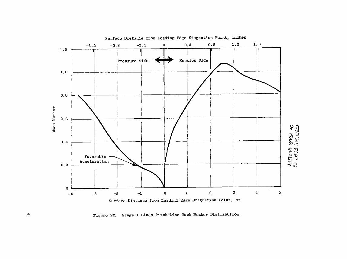
c i r c u i t s f o r t h e l e a d i n g and t r a i l i n g edges o f t h e b l a d e . The leading-edge c i r c u i t c o o l s t h e forward p o r t i o n o f the a i r f o i l by means o f a s e r p e n t i n e and c a s t impingement scheme. The t r a i l i n g edge is cooled by means o f a serpen- t i n e c i r c u i t i n the midchord r e g i o n and by a n impingementlpin-fin conf igura - t i o n a t t h e t r a i l i n g edge. The extreme t r a i l i n g edge of t h e b l a d e i s cooled b y p ressure - s ide s l o t f i lm-cool ing from t h e impingement pin-f i n c a v i t y . Sub- s t a n t i a l h e a t - t r a n s f e r improvement s have been gained by us ing t u r b u l e n c e pro- moters on tlre r i b s and by i n c o r p o r a t i n g a new, impinged-pin-fin, t r a i l i n g - edge-s lot d e s i g n . The impinged-pin-fin, t r a i l i n g - e d g e s l o t uses t h e p r e s s u r e a v a i l a b l e t o generate high i n t e r n a l h e a t t r a n s f e r and o f f e r s a 50% heat- t. m f e r improvement over a conven t iona l p in - f in d e s i g n . Other , more s u b t l e , improvements occur due t o t h e reduced a d v e r s e p r e s s u r e g r a d i e n t on t h e pres- s u r e s i d e o f t h e a i r f o i l , As shown i n F igure 22, t h e v e l o c i t y a long t h e pres- s u r e s i d e a c c e l e r a t e s a l l t h e way from the l e a d i n g edge t o t h e t r a i l i n g edge, T h i s should reduce t h e p o t e n t i a l f o r t h e boundary l aye r t o s e p a r a t e and r e a t t a c h . The end r e s u l t i s an a i r f o i l wi th lower gas s i d e heat t r a n s f e r corn- pared t o t h e product ion eng ine fami ly o f b l a d e s . The e x t e r i o r h e a t t r a n s f e r c o e f f i c i e n t s t h a t were used i n t h e a n a l y s i s are presen ted i n F i g u r e 23.
Stage 1 b lade cooling-system geometry d e t a i l s a r e i l l u s t r a t e d i n F igure 24. The S t a g e 1 blade-cooling system u t i l i z e s a t w o - c i r c u i t , convectj.on/film- cooled d e s i g n . In t h e forward c i r c u i t , leading-edge impingement h o l e s a r e supp l ied by a three-pass , convec t ion s e r p e n t i n e . Heat t r a n s f e r on t t e s i d e w a l l i n t h e s e r p e n t i n e i s s i g n i f i c a n t l y improved by t u r b u l e n c e promoters. The l ead ing edge o f t h e b l a d e i s cooled by 'a combination of impingement, convec- t i o n , and f i l m coo l ing . Af te r being h e a t e d i n t h e s e r p e n t i n e , t h e c o o l i n g a i r i n s imp. .$ed on the l e a d i n g edge. Spent impingement a i r p rov ides a d d i t i o n a l c o o l i n g through convec t ion i n the f i l m h o l e s as w e l l a s through e x t ~ r n a l f i l m cool ing. Leading-edge f i l m coo l ing i s supp l ied by t h r e e rows o f r a d i a l h o l e s . P ressure - s ide , f i lm-cool ing a i r i s s u p p l i e d through a s i n g l e row of round, a x i a l , f i l m h o l e s . Suct ion-s ide , f i lm-cool ing a i r is provided from s p e n t impingement a i r through a s i n g l e row o f d i f fusion-shaped , a x i a l , f i l m h o l e s . .
The a f t c i r c u i t c o n s i s t s o f a three-pass , forward-flowing s e r p e n t i n e . Due t o t e m p e r a t u r e l l i f e constraints, the t r a i l i n g - e d g e c o o l i n g a i r i s sup- p l i e d from t h e f i r s t pass of the s e r p e n t i n e . A f t e r f low mete r ing through a x i a l holes i n the crossover r i b , t r a i l i n g - e d g e c o o l i n g a i r i s impinged twice on two rows o f e q u a l l y spaced p i n s . The impinged-pin-fin d e s i g n reduces f low a r e a , i n c r e a s e s convect i o n h e a t - t r a n s f e r a r e a , and i n c r e a s e s f low t u r b u l e n c e . T h i s combinat ion of f e a t u r e s r e s u l t s i n e x c e l l e n t c o o l i n g e f f e c t i v e n e s s . Spent t r a i l i n g - e d g e c o o l i n g a i r e x i t s through 11 pressure - s ide b leed s l o t s and prov ides e x t e r n a l f i l m c o o l i n g f o r the r e m a h d e r o f the t r a i l i n g edge.
The b a l a n c e of the a f t - c i r c u i t cooling a i r c o n t i n u e s through t h e turbu- l a t e d s e r p e n t i n e and e x i t s through a s i n g l e row of p r e s s u r e - s i d e , midchord, f i l m h o l e s . These angled h o l e s p rov ide l o c a l convec t ion c o o l i n g a s w e l l as r e i n f o r c i n g t h e p ressure - s ide f i l m c o o l i n g from t h e upst ream, p r e s s u r e - s i d e , g i l l h o l e s . Tip-cap and s q u e a l e r - t i p c o o l i n g a r e accomplished by b l e e d i n g a smal l p o r t i q n of t h e c o o l i n g a i r through h o l e s i n t h e t i p cap a s shown i n F igure 25.


cd a
d
F,
OR
IGIN
AL PA
GE IS
n
OF POOR QU
ALITY
d 'I4
m
N
m 0
ii .rl m
a,
m
t-4 +
0
Q
w
0
0
M
b u
d
.rl r( 0 0
U a
m
U
C
..-I E
@
m
a
rl PI
A
aJ 3
C1 m
in m
w
(U
k
to 4
Fr
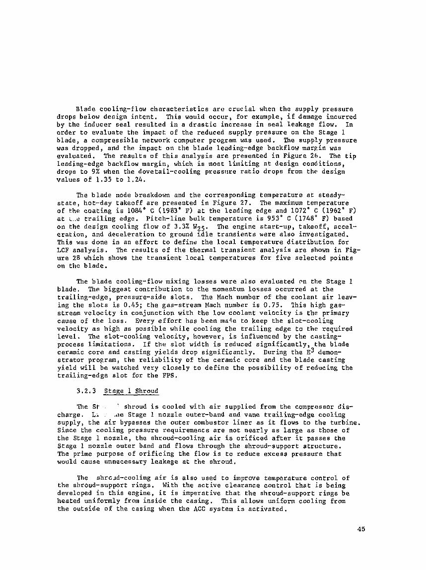
Blade cooling-flow c h a r a c t e r i s t i c s a r c c r u c i a l when t h e supply p r e s s u r e drops below d e s i g n i n t e n t . This would o c c u r , f o r example, i f damage incur red by t h e inducer s e a l r e s u l t e d i n a d r a s t i c i n c r e a s e i n s e a l Leakage flow. In o r d e r t o e v a l u a t e the impact o f the reduced supp ly p r e s s u r e on t h e Stage 1 blade, a compress ible network computer program was used. The supply p r e s s u r e was dropped, and t h e impact on the b lade leading-edge backflow margin was eva lua ted . The r e s u l t s o f t h i s a n a l y s i s a r e presented i n F igure 26. The t i p leading-edge backflow margin , which i s most l i m i t i n g a t d e s i g n c o n d i t i o n s , drops t o 9% when the dove ta i l - coo l ing pressr l re r a t i o d rops from t h e design v a l u e s o f 1 .35 t o 1.24.
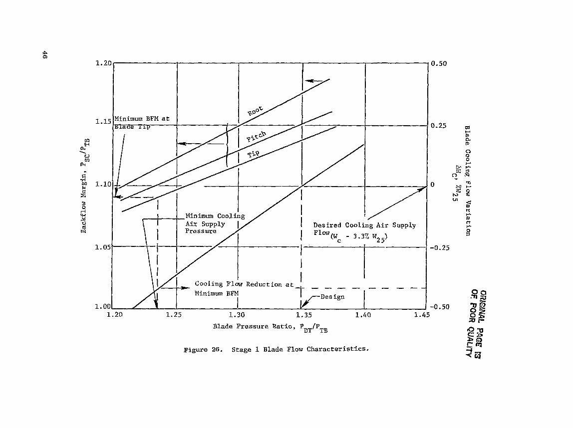
The b l a d e node breakdown and t h e corresponding t empera tu re a t steady- s t a t e , hot-day t a k e o f f a r e presented i n F i g u r e 27 . The maximum temperature o f the c o a t i n g i s 1084" C (1983" P) a t the l e a d i n g edge and 1072" C (1962" F) a t t.,e t r a i l i n g edge. P i t c h - l i n e b u l k t empera tu re i s 953' C (1748' F) based on the d e s i g n cool ing f low o f 3.3% W?5. The engine s t a r t - u p , t a k e o f f , acce l - e r a t i o n , and d e c e l e r a t i o n t o ground l d l e t r a n s i e n t s were a l s o i n v e s t i g a t e d . Th is was done i n an e f f o r t t o d e f i n e t h e l o c a l t empera tu re d i s t r i b u t i o n f o r LCF a n a l y s i s . The r e s u l t s o f t h e thermal t r a n s i e n t a n a l y s i s a r e shown i n Fig- u r e 28 which shows t h e ~ r a n s i e n t l o c a l t empera tu res f o r f i v e s e l e c t e d p o i n t s on the b l a d e .
The b l a d e cooling-Elow mixing l o s s e s were also eva lua ted r n t h e Stage I b l a d e . The b i g g e s t c o n t r i b u t i o n t o the momentum l o s s e s occur red a t t h e t r a i l i n g - e d g e , pressure-s ide s l o t s . The Mach number of t h e coo lan t a i r leav- ing the s l o t s i s 0.45; t h e gas-stream Mach number i s 0.75. This h igh gas- s t ream v e l o c i t y i n c o n j u n c t i o n wi th the low c o o l a n t v e l o c i t y i s the primary cause of t h e l o s s . Every e f f o r t has been made Lo keep t h e s lo t -coo l ing v e l o c i t y a s h i g h as p o s s i b l e whi le c o o l i n g t h e t r a i l i n g edge t o t h e requ i red l e v e l . The s lo t -coo l ing v e l o c i t y , however, i s in f luenced by t h e c a s t i n g - process l i m i t a t i o n s . I f the s l o t width is reduced s i g n i f i c a n t l y , the b lade ceramic c o r e and c a s t i n g y i e l d s d rop s i g n i f i c a n t l y . During t he E~ demon- strator program, t h e r e l i a b i l i t y of the ceramic core and t h e b l a d e c a s t i n g y i e l d w i l l be watched very c l o s e l y t o d e f i n e t h e p o s s i b i l i t y o f reduc ing t h e t r a i l i n g - e d g e s l o t f o r t h e FPS.
3 .2 .3 S t a g e 1 Shroud
The S t ' shroud i s cooled wi th a i r supp l ied from t h e compressor d i s - charge. Li .tie Stage 1 n o z z l e outer-band and vane t r a i l i n g - e d g e coo l ing supp ly , t h e a i r bypasses t h e o u t e r combustor l i n e r a s i t flows t o the t u r b i n e . S ince the c o o l i n g p r e s s u r e requiremefics a r e n o t n e a r l y a s l a r g e as those o f the Stage 1 n o z z l e , the shroud-cooling a i r is o r i f i c e d a f t e r it passes t h e S tage 1 n o z z l e o u t e r band and flows through t h e shroud-support s t r u c t u r e . The prime purpose o f o r i f i c i n g t h e flow i s t o reduce e x c e s s p r e s s u r e t h a t would cause unnecesssry l eakage a t the shroud.
The s h r c ~ d - c o o l i n g a i r i s a l s o used t o improve t empera tu re c o n t r o l o f t h e shroud-support rings. With t h e active c l e a r a n c e c o n t r o l t h a t i s being developed i n t h i s engine, it: i s impera t ive that t h e shroud-support r i n g s b e hea ted un i fo rmly from i n s i d e t h e cas ing . This al lows uniform c o o l i n g from the o u t s i d e o f the casing when the ACC sys tem i s a c t i v a t e d .
Blad
e Cooling P
low V
aria
tion
nno
Tempornturcs, ' C
T T ~ = 1396" C (2545O F)
TCIIT = 44" C I1lln F) 72
TCp = 628@ C (1162" F) 1037
~~cc,alnnt = 3.3% \Y25
TBlllk = 953' C (1748' P )
Figure 27. Stage 1 Blade Pitch-Line Temperature D i s t r i b u t i o n a t Steady-State Takeoff.

Tem
peratu
re, O
F
0000 o
oo
oo
oo
o
oo
oo
?
gg
oo
o
me
ua
ru
>m
mr
c
Xa
00
08
ga
o
04
rl
dr
l
rl
H.
Id
rl
rl
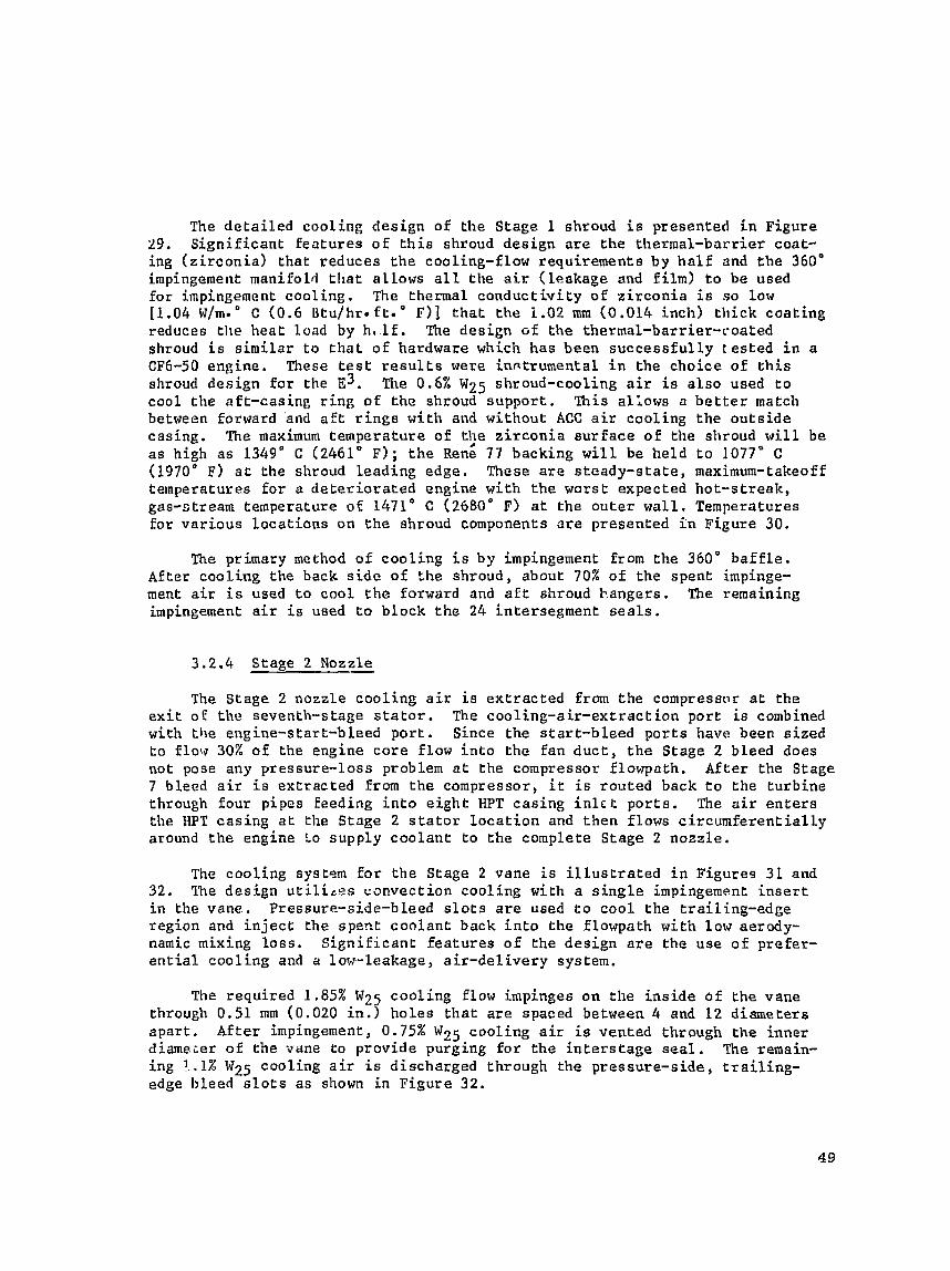
The d e t a i l e d coo l ing de s ign o f t h e S tage 1 shroud i s presented i n Figure 29. S i g n i f i c a n t f e a t u r e s o f t h i s shroud d e s i g n a r e the the rmal -bar r i e r coat- i n g { z i r c o n i a ) t h a t r educes t h e cooling-£ low requ i rements by h a l f and the 360" impingement manifold t h a t a l lows a l l . t h e a i r ( l eakage and f i l m ) t o be used For impingement c o o l i n g . The thermal c o n d u c t i v i t y of z i r c o n i a is so low [1.04 ~ / m - " C (0 .6 l l tu /h r - f t . " F ) ] t h a t the i .02 mm (0.014 inch) t h i c k c o a t i n g reduces t h e h e a t l oad by h a l l £ . The d e s i g n of the thermal-barr ier-coated shroud i s s i m i l a r t o t h a t o f hardware which has been s u c c e s s f u l l y tesLed i n a CF6-50 engine. These t e s t r e s u l t s were inrrtrumental i n t h e choice of e h i s shroud des ign f o r the E ~ . The 0.6% W25 shroud-cooling a i r i s a l s o used t o cool t h e a f t -cas ing r i n g of the shroud s u p p o r t . This a l lows a b e t t e r match between forward and a f t r i n g s w i t h and wi thou t ACC air coo l ing t h e o u t s i d e cas ing . The maximum tempera tu re o f t t e z i r c o n i a s u r f a c e o f t h e shroud w i l l be as high a s 1349" C 12461" F); t h e Rene 77 backing w i l l be h e l d t o 1077" C (1970' F) a t the shroud l e a d i n g edge. These are s t e a d y - s t a t e , maximum-takeoff temperatures f o r a d e t e r i o r a t e d engine wi th t h e worst: expected hot-s t r e a k , gas-otream temperature of 1471" C (2680" F) a t t h e o u t e r w a l l , Temperatures f o r v a r i o u s l o c a t i o n s on t h e shroud components a re p resen ted i n F igure 30.
The primary method o f cooling i s by impingement Erom t h e 360" b a f f l e . Af te r c o o l i n g t h e back side of the shroud, about 70% of t h e spen t impinge- ment air i s used t o coo l t h e forward and a f t shroud b,angers. The remaining impingement air i s used t o b lock the 24 in te r segment s e a l s .
3.2.4 Stage 2 Nozzle
The S tage 2 nozzle c o o l i n g a i r is e x t r a c t e d Erom t h e compressnr a t t h e e x i t of the seventh-stage s t a t o r . The c o o l i n g - a i r - e x t r a c t i o n p o r t is combined with t h e engine-s tar t -bleed p o r t . Since the s t a r t - b l e e d p o r t s have been s i z e d t o flow 30X of the engine c o r e f low i n t o t h e f a n d u c t , t h e Stage 2 bleed does not pose any p ressure - loss problem a t t h e compressor f lowpath. After t h e Stage 7 bleed a i r i s e x t r a c t e d from t h e compressor, i t i s r o u t e d back t o t h e t u r b i n e through four p ipes feeding i n t o e i g h t HPT c a s i n g i n l c t p o r t s . The a i r e n t e r s the HPT c a s i n g a t the Stage 2 s t a t o r l o c a t i o n and t h e n flows c i r c u m f e r e n t i a l l y around t h e engine Lo supp ly c o o l a n t t o the complete S tage 2 nozz le .
?'he c o o l i n g sysrem f o r t h e Stage 2 vane i s i l l u s t r a t e d i n F igures 31 and 32. The d e s i g n u t i l i a e s c o n v e c t i o n coo l ing wi th a s i n g l e impingement i n s e r t i n the vane.. Pressure-s ide-bleed s l o t s a r e used t o c o o l t h e t r a i l i n g - e d g e r e g i o n and i n j e c t the specc c o o l a n t back i n t o t h e f lowpath wi th low aerody- namic mixing l o s s . S i g n i f i c a n t f e a t u r e s o f t h e d e s i g n are the use o f p re fe r - e n t i a l c o o l i n g and a low-leakage, a i r - d e l i v e r y system.
The r e q u i r e d 1.85% W25 c o o l i n g flow impinges on t h e i n s i d e o f t h e vane through 0.51 ma (0.020 i n . ) h o l e s t h a t a r e spaced between 4 and 12 d iamete r s a p a r t . A f t e r impingement, 0.75% W25 c o o l i n g air i s vented through t h e i n n e r d iameier o f t h e vane t o p rov ide purging f o r t h e i n t e r s r a g e s e a l . The remain- ing !.I% W25 coo l ing a i r i s d i scharged through the p r e s s u r e - s i d e , t r a i l i n g - edge bleed s l o t s as shown i n F i g u r e 32.
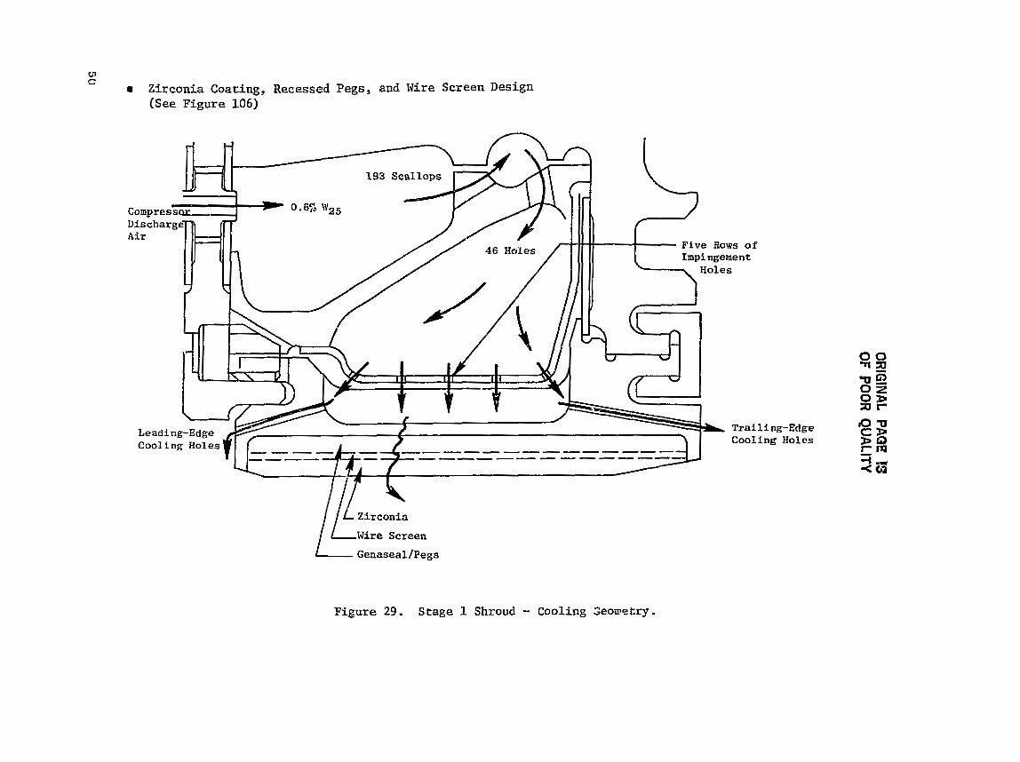
OR
IGIN
AL PA
GE 13
OF BOOR QU
ALITY

OR
IGIN
AL PA@
?S
OF POOR Q
UA
LIW

f nscrt/Vane
Low-Pressure- Drop Spool iu P r e f e r e n t i a l
Tr ai 1 i ng-Ed ge Cooling C i r c u i t
Edge Holes
Positive Caolanf- Backflow Margin Pref ercntial
Impingement
C o o l e d Band Leading Edge
Interstage-
Figure 31. Stage 2 Nozzle Design Features .

7th Stage Compressor A i r
0.35% Shroud Purge
0.15% Purge (Leakage)
Impingement Insert Diameter 0.51 mm (0.020 in.)
Squiggly Lines to Denote Lezkage
Figu re 32. Stage 2 Nozzle Cool ing Flows.

The gas-temperature p r o f i l e ana lys i s ind ica ted a maximum peak tempera- ture OF 1337" C (2439" F) a t 65% span and 1190" C (2174" F) a t 95% span. From production-engine experience, the l i f e - l i m i t i n g a r e a o f t h e Stage 1 vane i s expected t o be the 95% span. The gas-bending loads on the nozzle r e s u l t i n high s t r e s s e s i n the vane leading edge a t t h i s s ec t ion . The vane thermal a n s l y s i s was conducted not on ly a t ehe high-gas-temperature vane sec t ion bu t a l s o a t t h i s high-mechanical-load sec t ion . The impingement cooling was adjusted by changes i n hole spacing t o accommodate the expected v a r i a t i o n i n h e a t load and required temperatures, The node breakdown and temperature d i s t r i b u t i o n a t the 65% and 95% span a r e presented i n Figure 33. The bulk rnetal temperatures a t these vane sec t ions a re 928" C (1702" F) and 972" C (1781' F), r e spec t ive ly ,
3.2.5 Stage 2 Rotor
The Stage 2 r o t o r blade i s cooled with compressor-discharge a i r supplied through the Stage 1 rotor expander nozzle system and de l ivered t o the Stage 2 b l ade by means of flow passages down the f r o n t side and under the Stage 1 d i s k . The a i r i s then pumped up the f r o n t s i d e of the Stage 2 d i s k and enters the dove ta i l d i s k s l o t from the f ron t s i d e .
The Stage 2 blade cool ing system, as shown i n Figure 3 4 , i s a two- c i r c u i t , internal-convect ion design. I n the forward c i r c u i t , cooling a i r is forced through a three-pass serpent ine . A high leading-edge cooling e f fec- t i veness i s achieved by flowing f r e s h cool ing a i r through a small a r e a near t h e leading edge. The cooling e f f e c t i v e n e s s i n the se rpen t ine passages i s improved by two-dimensional ( r ib- type) , turbulence promoters. The aerodynamic mixing lo s ses have been reduced by means of a pressure-side- t ip , rnidchord s l o t . The high v e l o c i t y of the s l o t cool ing a i r energ izes t he mainstream gas flow and improves turbine e f f i c i ency .
The a f t c i r c u i t i s very s imi l a r t o t he forward c i r c u i t . Cool, f r e s h a i r i s brought from the blade d o v ~ c a i l through a small , s e rpen t ine passage located nea r the t r a i l i n g edge, Af te r cooling t h e t r a i l i n g edge, t h e a i r cont inues t o coo l t h e b lade i n two add i t i ona l passages. A s i n the forward c i r c u i t , turbu- l ence promoters a r e extended onto the r i b s f o r increased cool ing e f f ec t ive - nes s . The spent a i r from the a f t c i r c u i t a l s o e x i t s through a s i n g l e s l o t on t h e pressure s i d e near the t i p .
The gas-temperature p r o f i l e analysis ind ica ted a p i tch- l ine design va lue of 1038" C (1900' F) with a coolant-supply temperature of 593" C (1099" I?). The de ta i l ed ana lys i s indicated t h a t a s a t i s f a c t o r y 929" C (1705" I?) bulk metal temperature could be achieved with 0.76% W25 f o r b lade cooling.
The d e t a i l e d thermal-model node breakdown and the l o c a l metal tempera- t u r e s a t the hot-day , s teady-s t a t e , t akeoff condi t ion a r e presented i n Figure 35. The maximum temperature of 1013" C (1855" F) occurs a t the t r a i l i n g edge on the environmental coat ing. The t r a i l i n g edge was the moat d i f f i c u l t pa.rt cf the blade t o cool because i t i s i n a high-heat- t ransfer-coeff icient envis-c.- ronmenC. Becatlse of the d i s t a n c e of t h e t r a i l i n g edge from the l a s t r a d i a l
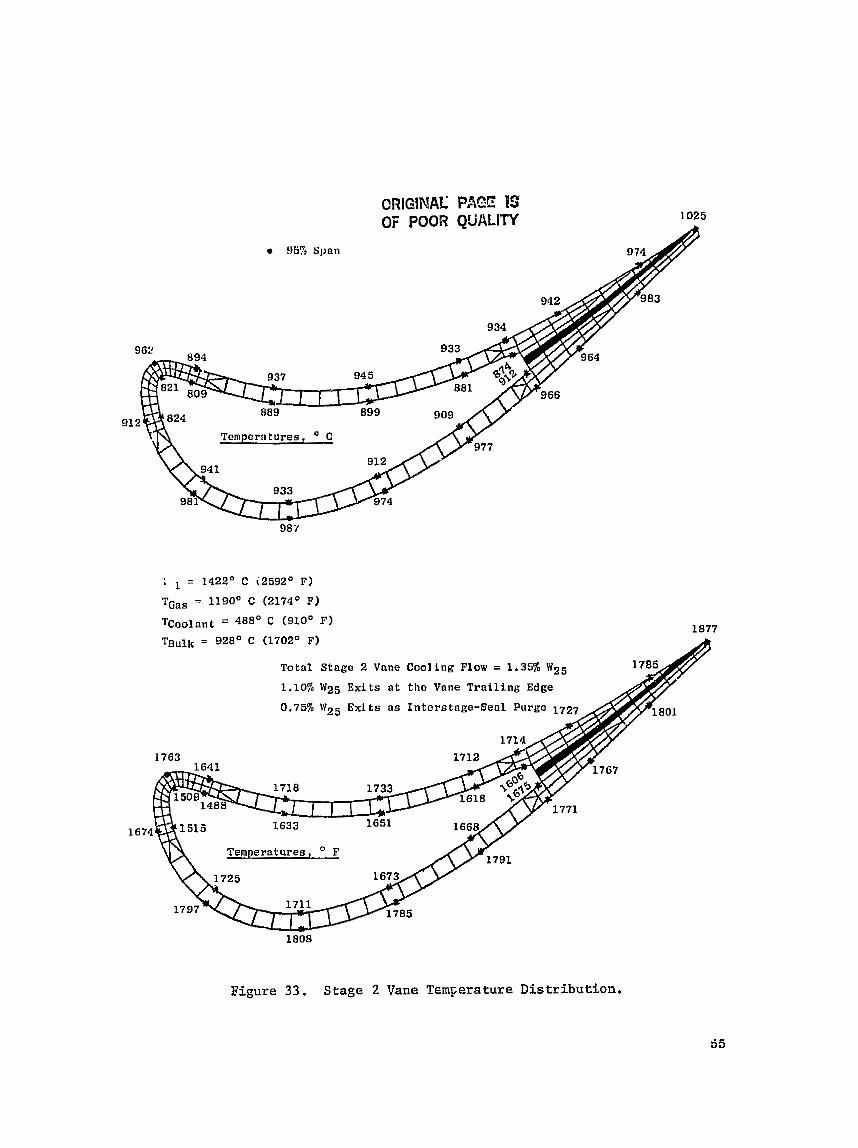
CRIGINAL PAGE FS OF POOR QUALITY
- - -
Tempcrntures, " C -- -
'1 = 1422" C i259Z0 F)
TGas = 1190' C (2174' F)
T ~ ~ ~ l ~ n t = 488' C (910' F) 1877
T ~ ~ l k = 928' C (1702' F)
Totnl Stage 2 Vane Cooling Flow = 1.35% WZ5
1.10% lV25 Exits a t the Vane Trniling Edge
0.75% q6W25 Exits ns Interstnge-Seal Purge 17
Temperatures, * F
1808
Figure 33 . Stage 2 Vane T~m~erature Distribution.

LH?IG!NAL PAGE Es OF PGOR QUALITY
65% Spnn
1667 Tornperntures, F
Vigure 33. Stage 2 Vane Temperature D i s t r i b u t i o n (Concluded).

0.38% W25 A f t Slot 0.635 x 3.66 mm
0 0
'V2 5 *d Slot x 3.02 mm x 0.119 in.)
r Cast Re& 150 B l a d e s
r PVD Coating
e Serpentine Convection Cooling
a No Film-Cooling or Trailing-Edge Holes
T i p , Pressure-Side Coolant Eject ion f o r Cooling Exit and Increasing Torque
r Turbulence Promoters on Ribs and A i r f o i l Walls
0.35% 0.41%
C.7% \V25 I
Figure 34. Stage 2 Blase D e s i g n Features.
Temperatures, O C
Temperatures, O F -
Figure 35. Stage 2 Blade Pi tch-Line Temperatures a t Steady-State Takeoff.

cav i ty , i n t e r n a l cool ing a i r i n the o r i g i n a l conf igura t ion had a minimum impact on the t rai l ing-edge temperature. Subsequently, t he t rai l ing-edge wedge angle was increased t o t h e present va lue t o improve conductive cooling and al low t h e l a s t r a d i a l cav i ty t o be moved c lose r t o the t r a i l i n g edge. With these imprc +-ments, the needs f o r a f a t t e r t r a i l i n g edge and t r a i l i n g - edge, convection-slot cool ing were both eliminated.
Produc tian-engine experience ind ica t e s t h a t tu rb ine hardware can experi- ence foreign object damage IFOD). Because of t h i s and Lhe unique na ture of t h e Stage 2 blade cool ing c i r c u i t , an FOD a n a l y s i s was conducted. The pur- pose of t h i s ana lys i s was t o de f ine the cooling-flow v a r i a t i o n t o the blade i f a ho le caused by FOD penetrated the leading-edge, r a d i a l , cool ing passage. With an assessed FOD ho le up t o 0.63 cm (0.25 i n . ) i n diameter a t the 60% span, t he leading-edge flow c i r c u i t flow i s increased qu i t e d r a s t i c a l l y . A t the same time, the flow t o the second and t h i r d r a d i a l c a v i t i e s drops , The corresponding p i tch- l ine temperature d i s t r i b u t i o n with and without t he 0.63 cm (0.25 i n . ) diameter ho le i s presented i n Figure 36. This ana lys i s shows a 37" C (67' F) drop i n t he bulk metal temperature. The biggest v a r i a t i o n occurs a t the leading edge where the i n s i d e sur face of the a i r f o i l wal l drops as much a s 101" C (182" F). This ana lys i s i nd ica t e s t h a t a ca t a s t roph ic l o s s of Stage 2 blades due t o t y p i c a l FOD i s very unl ike ly .
A s i m i l a r ana lys is was conducted on the blade t i p cap. The tip cap w i l l be made i n one piece and brazed i n place with no mechanical r e t e n t i o n device. This c o n c e ~ t is f e a s i b l e because thc b lade- t ip gas temperatures i n Stage 2 a r e r e l a t i v e l y low. A thermal ana lys i s was conducted t o determine the impact of a braze f a i l u r e and t i p cap l o s s . A compressible-flow network program, as i n t he previous ana lys i s , was used f o r t h i s a n a l y s i s . Without the t i p cap, the core support holes became the flow--circuit r e s t r i c t i o n , and t h e blade flow increased from 0.76% W p j t o 2.39% W Z ~ . The flow increased i n a l l r a d i a l c a v i t i e s . This ana lys i s indicated no problem i f a Stage 2 blade l o s t i t s t i p cap,
3.2.6 Stage 2 Shroud - Detai led temperatures fo r s teady-s ta te takeoff and the i d l e - takeoff -
i d l e t r a n s i e n t have been ca lcu la ted f o r t h e Stage 2 shroud. Because of the low gas temperaLure a t t he Stage 2 shroud, 1140" C (2084" F), no s i g n i f i c a n t cooling was requi red . A t o t a l of 0.35% W25 seventh-stage compressor bleed a i r i s used t o purge the c a v i t y around the Stage 2 shroud i n order t o prevent hot-gas i nges t ion from overheat ing the HPT casing. There are 24 shroud seg- ments; t h e gaps between each segment w i l l be sealed with one a x i a l hour-glass s ea l and one s p l i n e s e a l .
3.2.7 Rotor S t ruc tu re - The manufacturing cos t o f KPT r o t o r s t r u c t u r e i s r e l a t i v e l y h igh and
usual ly becomes one of t he l imi t ing i tems i n t he thrust-growth development of an engine. In order t o overcome t h i s problem, the E~ t u rb ine r o t o r has been
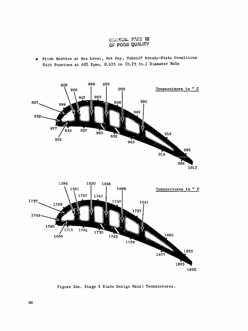
Pitch Sect ion a t Sea L e v e l , Hot Day, Takeoff Stoady-Stntc Conditions
With Puncture a t 60% Span, 0,635 cm (0 .25 in.) Diameter Hole
862 888 920 \ 866 I 1 9?0 Temperatures in O C
1688 Temperatures in O F \ 7 2 I 7 4 7 I I
Figure 36a. Stage 2 Blade Design Metal Temperatures.
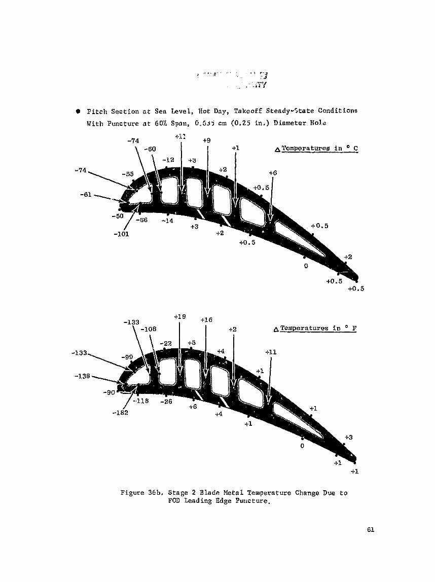
P i t c h Sect ion a t Sea Level, Hot Day, Takeoff Steady-State Conditions
With Puncture a t 60'L Span, 6 . 5 3 5 cm (0.25 in.) Diameter Ko3.e
A Temperatures f n 2
-133
-1 3
FFgure 36b. Stage 2 Blade Metal Temperature Change Due to FOD Leading Edge Pur~cture.

designed f o r n g r c a t b engine t h a t has a 15% t o 20% higher t h r u s t l e v e l . The growth engine has higher compreosor-exit temperature, tu rb ine- in le t tempera- t u r e , pressure, and r o t o r speed. This growth condit ion was used t o d e f i n e the r o t o r s t r u c t u r e des ign and temperatures . The FPS r o t o r was analyzed, bu t i n a l l ' c a s e s the growth engine was more l i m i t i n g .
For the hea t - t r ans fe r a n a l y s i s , the t r a n s i e n t boundary condit ions were evaluated by means o f f l u i d nodes i n a ~ i m p l f i e d , t r a n s i e n t , thermal model. The r e s u l t s of t h i s model were checked aga ins t the ACC t r a n s i e n t model of t he r o t o r s t r u c t u r e , !these t r a n s i e n t a i r temperatures and hea t - t ransfer cae f f i - c i e n t s were then used i n the d e t a i l e d thermal model presented i n Figure 37. This de ta i l ed model exyended from t he a f t end of the compressor to the LPT bearing iii+J included the LPT s h a f t . The model conta ins 908 nodes, eight: d i f - f e r e n t matec ia l s , and 183 boundary-condition t ab l e s covering 44 time inputs of temperature and hea t - t ransfer c o e f f i c i e n t s .
The t r a n s i e n t ana lys i s cons is ted of a complete mission from cold engine s t a r t through the f l i g h t mission and engine shutdown, a s presented e a r l i e r i n F i g u r e 11, Extensive i t e r a t i o n s and f e a s i b i l i t y s t u d i e s were conducted i n an e f f o r e to y i e l d a t r a n s i e n t temperature d i s t r i b u t ian t h a t would not overs t r e s s any component. The areas thct presented the b igges t cha l lenges were:
e Compressor Discharge Sea l Disk Bolt Flange
r Inducer Seal Disk Bolt Flange
Impeller Disk Rore and Rabbet
Stage 1 Disk Bore
Intersbage-Seal Disk Bolt C i r c l e and Seal Teeth
Stage 2 Disk Bore
Aft-Seal Disk Bolt C i r c l e
A l l problem areas were the r e s u l t o f t r a n s i e n t temperature g rad ien t s except a t t h e i n t e r s t age disk s e a l t e e t h ( temperature l imi t ed ) .
Because of t h e massiveness of the d i s k bores , the thermal responses o f t h e s e components were very slow. This condi t ion c rea ted l a r g e temperature g r a d i e n t s during the early p a r t o f the takeoff t r a n s r e n t . The in te rs tage- s e a l b o l t circle a l s o presented a severe thermal-s tress problem caused by t h e massiveness of the b o l t s , f lange , and d i s k a s compared t o the outer s e a l r i n g . The thermal response of the ou te r por t ion of the disk was very quick a f t e r cn accel , bu t the bore and b o l t c i r c l e responded s luggish ly . I n o rde r t o overcome t h i s problem, s l o t s were machined i n the b o l t f langes , and a small q u a n t i t y o f a i r was used t o convect ively hea t t he b o l t f lange from both s i d e s , a s shown in Figure 38. This modif ica t ion increased t he f lange temperature by 56" C (100" F ) a t the c r i t i c a l condi t ion . When the improved cooling of t h e b o l t f lange was combined with an improved mechanical design, the liEe objec- t ive was achieved .


OR
IGIN
AL PA
CE 13
OF PO
OR Q
UA
LITY
Another problem occurred a t the bore of t he Stage 2 d i sk . The a x i a l and r ad ia l thermal s t r e s s e s combined t o l i m i t the t r a n s i e n t rup tu re l i f e a t t h a t loca t ion , This problem was overcome when the heat t r a n s f e r t o the bore was increased. This increased t h e t r a n s i e n t temperature a t t he bore su r f ace and caused a h igher thermal compressive s t r e s s . When combinad with the mechani- c a l t e n s i l e s t r e s s , the e f f e c t i v e s t r e s s was reduced. The end result was a diek t h a t met t h e r o t o r s t r u c t u r e - l i f e ob jec t ives of the growth engine. fie improved heat transBer t o t h e bore was accomplished by increas ing t h e flow under the d i e k t o 0.2% W25 and reducing t h e r a d i a l gap from 0.254 t o 0.127 cm (0.10 t o 0.05 i n . ) .
3.2.8 Casing
The thermal a n a l y s i s o f t he HPT cas ing i s presented i n Figure 39. During t h i s a n a l y s i s , p a r t i c u l a r emphasis was placed on evaluat ing t h e t r a n s i e n t tem- perature g r a d i e n t s i n the r ings l f l anges . The o r i g i n a l a n a l y s i s ind ica ted t h a t the transient-induced temperature g rad ien t s were r e s u l t i n g i n high e f f e c t i v e t e n s i l e hoop s t r e s s e s i n the casing f lange bo l tho le edge over the Stage 2 noz- z l e even without ACC. The r abbe t was moved from the ou t s ide of t he f lange t o the i n s i d e , and the f lange was thickened t o enhance conduction and reduce the dead weight of the b o l t spacer. The 0.35% W 2 5 a l loca t ed f o r Stage 2 shroud purge was used first t o cool the Stage 2 nozzle b o l t f lange by de l iver - ing the a i r t o t h e shroud cavi ty through 0.381 x 0.127 cm (0.15 x 0.05 in . ) s l o t s i n t he b o l t f lange. This approach r e s u l t s i n a cooler bolt f lange and a reduced t ransient- temperature grad ien t .
This rhermal a n a l y s i s was performed on the cas ing hardware t h a t extended from the combustor a f t casing through the HPT and back t o the EPT nozzle sup- port s t r u c t u r e . The coolantf leakage flows were defined along with the gem- e t r y requi red t o achieve the ob jec t ive flows. The thermal model ( ~ i g u r e 40) contained 180 nodes, 35 temperature and hea t - t ransfer -coef f ic ien t boundary condit ions, and 35 i q j u t time s t e p s . A few of the temperatures a t steady- s t a t e , hot-day takeoff f o r t h e base FPS engine are presented i n Figure 4 0 . The t r a n s i e n t hea t - t r ans fe r ana lys i s included the e f f e c t s of t h e nominal ACC cooling on the outs ide of the casing. This ACC cool ing was i n i t i a t e d a t the end of the 2-minute takeoff and continued t o the s teady-s ta te c r u i s e condi t ion a t 10.67-km (35,000-ft) a l t i t u d e .
Stage 1 Nozzle Support S t ruc tu re
The thermal ana lys i s of the Stage 1 nozzle support s t r u c t u r e cons is ted of the thermal- t ransient eva lua t ion of the outer combustor cas ing , compressor e x i t p red i f fuee r , inner combustor-discharge seal, inducer , and inducer s e a l . The t r ans i en t included the complete engine f l i g h t mission.
O f p a r t i c u l s r i n t e r e s t were the inducer and inducer s e a l s i n c e they a r e both c r i t i c a l t o the turb ine- ro tor , air-uupply system. The inducer a i r f l ow obtained i n the a i r - t u rb ine t e s t was evaluated and found t o be high, There- fore, the inducer width was reduced i n an e f f o r t to increase the v e l o c i t y leaving the inducer and t h u s improve the v e l o c i t y match with the ro to r .

ORIGINAL Paae ts OF POOR QUALITY
Figure 3 9 . Casing Cooling Flow Distribution.

ORIGINAL PP.CE F5 OF POOR QdALIYII
r No Active Clearance Contrn?
Temperatures, C
Temperatures, O F
Figure 40. Casing Steady-State Takeoff Temperature Distribution.

Inducer s e a l leakage can s i g n i f i c a n t l y a f f e c t the performance of the tur- bine-cooling system as wel l aa the turb ine aerodynamic performance, Because of this, extensive stirdies were conducted t o d e f i n e the b e s t approach to mini- mize the leakage of t h e inducer s e a l . A dynamic c l ea rance model was s e t up and used t o d e f i n e the t r a n s i e n t c learances during t h e engine mission. Of p a r t i c u l a r i n t e r e a t were the engine start/warm-up/accel-to-max t akeoff mission cyc le and h o t r o t o r r ebu r s t a t c r u i s e . The engine-acceptance, t akeo f f , hot- r o t o r reburst was also evaluated.
Since there i s no ACC system on the s e a l , i t was imperative t h a t the beet passive system be found, Early i n t h e anaLysis i t became evident t h a t a ma te r i a l with a low thermal c o e f f i c i e n t of expaasion was needed for the sca- t io'iary eea l . Inco 903A had been se lec ted f o r t h e compressor-discharge seal, b u t the inducer s e a l temperature [over 649" C (1200" F)] prohib i ted the use of t h i s unique m a t e r i a l . The problem was resolved by t h e in t roduct ion of 0.1% W Z 5 compressor discharge a i r t o cool t he back side of the s e a l . This reduced t h e base engine temperature bzlow 649" C (1200" F) ~ n d allowed the use of Inco 903A mater ia l which reduced the c learances d rama t i ca l ly ,
Tl-2 mass of the s t a t i o n a r y inducer seal was also evalua ted . The analy- s i s showed t h a t a more massive s e a l improves the c learance a t c r u i s e by 0.005 cm (0,002 i n . ) s ince the hot r o t o r r ebu r s t i s na t as severe , However, a t takeoff pinch c learance i s reduced 0.010 cm (0.004 i n . ) and may be a more l i m i t i n g condition than a t c r u i s e . During the core and ICLS t e s t s , t he ther- mal- t ransient responc?? o f t h i s s ea l w i l l be monitored very c l o s e l y t o v e r i f y t h e need of t he increased s e a l mass. The worst transient w i l l be evaluated, and the seal-tooth rubs w i l l be checked a f t e r t e s t so t h a t a bench mark can be obtained t o de f ine t r a n s i e n t c learances .
ACTIVE CLEARANCE CONTROL SYSTEM
GENERAL DESCRIPTION
One o f t h e prime f e a t u r e s o f the E~ HPT i s a c t i v e c l e a r a n c e c o n t r o l . E x t e n s i v e e f f o r t s have been made t o unders tand and implement t h e ACC sys tem, To unders tand t h e system, i t i s impera t ive t h a t t h e r e l a t i o n s h i p of r a d i o 1 c l e a r a n c e between t h e t u r b i n e r o t o r and s t a t o r be de f ined along wi th t h e e f f e c t e on performance.
I n an a i r c r a f t engine t h e s e c l e a r a n c e s tend t o v a r y c o n s i d e r a b l y because o f o p e r a t i o n o v e r wide ranges o f r o t o r speed and temperature . During a t y p i - c a l f l i g h t , many changes i n power a r e made which c w s e r e l a t i v e mechanical and thermal movement between s e a l t e e t h , o v e r l a p s , qnd \ l a d e t i p s . A d d i t i o n a l d e f l e c t i o n s a r i s e due t o t r a n s i e n t f l i g h t l o a d s , imposed on t h e eng ine , and e n g i n e v i b r a t i o n . When t h e normal manufactur ing t o l e r a n c e s of t h e many mat ing e n g i n e p a r t s a r e cons ide red , e s p e c i a l l y t h o s e which a f f e c t r o t o r / s t a t o r eccen- t r i c i t y , i t c a n b e ext remely d i f f i c u l t t o m a i n t a i n c l o s e running c l e a r a n c e s throughout (:he o p e r a t i n g enve lope ,
I n a l lowing f o r random f l i g h t l o a d s , eng ine v i b r a t i o n , and t o l e r a n c e v a r i - a t i o n s , a des i r ed minimum running c l e a r a n c e can be c a l c u l a t e d . Th i s c l e a r a n c e c a n vary a t d i f f e r e n t o p e r a t i n g p a i n t s , b u t i n g e n e r a l i t can be shown t h a t a l a r g e r c l e a r a n c e is requ i red a t t a k e o f f than a t c r u i s e .
After t h e f a c t o r s t h a t l e a d t o a m i n i m u m running c l e a r a n c e a r e determined, t h e c l e a r a n c e e f f e c t s of r a p i d eng ine power changes must be determined. These t r a n s i e n t c l e a r a n c e requ i rements can be l a r g e r than a l l o t h e r e f f e c t s combined. A s k e t c h i n d i c a t i n g t h e v a r i a t i o n of c l e a r a n c e d u r i n g an eng ine t r a n s i e n t is shown i n Figure 41. During a c c e l e r a t i o n , t h e r o t o r d iamete r i n c r e a s e s w i t h i n c r e a s i n g c e n t r i f u g a l f o r c e . A f t e r a steady-$ t a t e speed is achieved, t h e r o t o r d iamete r c o n t i n u e s t o i n c r e a s e a t h igh power a s . t h e rotor mass tempera- t u r e i n c r e a s s s . A t t h e same t i m e , t h e c a s i n g d iamete r i n c r e a s e s d u r i n g aper - a t ion a t h igh power a s t h e mass approaches i n t e r n a l - a i r € low tempera tu res , Reverse e f f e c t s occur dur ing d e c e l e r a t i o n wi th the r o t o r d iamete r aga in respond- i n g i n i t i a l l y f a s t e r than t h e s t a t o r . With a n uncooled c a s i n g , a minimum b l a d e clearance must b e mainta ined fo r the s m a l l e s t t r a n s i e n t c l e a r a n c e ; t h a t o c c u r s a few seconds a f t e r a c c e l e r a t i n g t h e engine t o t a k e o f f power, As a r e s u l t , t h e t i p c l e a r a n c e which occurs o v e r most of t h e remaining miss ion i s l a r g e r than t h e d e s i r e d minimum running c l e a r a n c e . To m i t i g a t e t h e excees c l e a r a n c e , the c a s i n g i s uncooled dur ing t a k e o f f ; then c o o l i n g i s g r a d u a l l y a p p l i e d through t h e cl imb and c r u i s e port ionrt o f t h e m i s s i o n t o reduce t i p c l e a r a n c e toward t h e minimum d e s i r e d running c l e a r a n c e , a s i l l u s t r a t e d by t h e dashed l i n e i n F i g u r e 41. With the coo l ing sys tem employed i n t h i s example, even t i g h t e r c l e a r a n c e s are p o s s i b l e , a s shown by the d o t t e d l i n e , b u t app ly ing t h i s much c o o l i n g may r e s u l t i n e x c e s s i v e wear and d e t e r i o r a t i o n under normal f l i g h t and eng ine -opera t ing c o n d i t i o n s . The o n l y t ime t h a t the maximum coo l ing would be a p p l i e d would be a t a minimum c r u i s e power s e t t i n g .

ORIGlNAL PA:;:< I;; OE POOR QUAL!TY
Representative rrtiAbiire Stage
Idle 'frk*cm c h b - 4 r wi. Er. I I I 1 1 1 1 1 1 I I r V ~ r r I ITIII
loo Time, sec 1000 10,000
Figure 41, Activt: C1.e;rance Cont ro l Opera t i o n .
\ Cooling Circuit
Exhaust
Pressure Zone
r Operation - Separate Fan-Air Modulating Valves (2) for HPT and LPf - Sorno Opening of Clearance at SLTO - Control by FAOEC
Figure 42 . HPT/LPT ACC Coaling System.
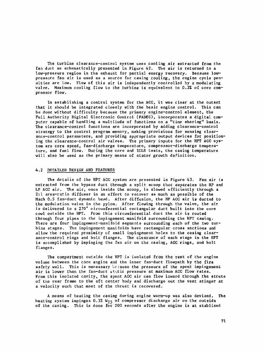
The t u r b i n e c l e a r a n c e - c o n t r o l system u s e s c o o l i n g a i r e x t r a c t e d Erom t h e f a n duc t a s s c h e m a t i c a l l y p resen ted i n Figure 42. The a i r i s r e t u r n e d t o a low-presnure r e g i o n i n t h e exhaust f o r p a r t i a l energy recovery . Because low- p r e s s u r e fan a i r i s used a s a source fo r c a s i n g c o o l i n g , t h e eng ine c y c l e pen- a l t ies a r e low, Flow o f t h i s a i r i s independent ly c o n t r o l l e d hy a arodulat ing va lve . Maximum coo l ing f low t o the t u r b i n e i s e q u i v a l e n t t o 0.3X of core com- p r e s s o r f low.
I n e a t a b l i s h i n g a c o n t r o l system f o r t h e ACC, i t was c l e a r a t t h e o u t s e t t h a t i t should be i n t e g r a t e d c l o s e l y wi th the b a s i c e n g i n e c o n t r o l . T h i s c a n be done w i t h o u t d i f f i c u l t y because the primary eng ine -con t ro l e lement , t h e F u l l A u t h o r i t y D i g i t a l E l e c t r o n i c Cont ro l (FADEC), incorporates a d i g i t a l com- p u t e r c a p a b l e of hand l ing a m u l t i t u d e of f u n c t i o n s on a "time sha r ing" b a s i s . The c l e a r a n c e - c o n t r o l f u n c t i o n s a r e incorpora ted by adding c l e a r a n c e - c o n t r o l s t r a t e g y t o t h e c o n t r o l program memory, making p r o v i s i o n s f o r sens ing c l e a r - ance-control parameters , and p rov id ing a p p r o p r i a t e o u t p u t d e v i c e s f o r p o s i t i o n - ing the c learance-controL a i r va lves . The primary i n p u t s f o r the HPT ACC sys- tem are c o r e speed, fan-discharge t empera tu re , compressor-discharge tempera- t u r e , and f u e l f low. During t h e c o r e and ICLS t e s t s , t h e c a s i n g t empera tu re w i l l a l s o be used as khe primary means of s t a t o r growth d e f i n i t i o n ,
4. . 2 DETAILED DESIGN AND FEATURES -- The d e t a i i s o f the HPT ACC system a r e presented i n F igure 43. Fan a i r i s
e x t r a c t e d Erom the bypass d u c t through a s p l i t scoop that s e p a r a t e s t h e HP and LP ACC air. The a i r , once i n s i d e t h e scoop, i s slowed efficiently through a 2 : l a r e a - r a t i o d i f f u s e r i n an e f f o r t t o r ecover as much a s p o s s i b l e of the Mach 0.5 fan-dact dynamic head. A f t e r d i f f u s i o n , the HP ACC a i r i s ducted t o t h e modula t ion v a l v e i n t h e pylon. After f lowing through t h e v a l v e , t h e a i r i s d e l i v e r e d t o a 270' c i r c u m f e r e n t i a l r e c t a n g u l a r d u c t b u i l t i n t o the c o r e cowl o u t s i d e t h e HPT. From t h i s c i r c u m f e r e n t i a l d u c t t h e a i r i s rou ted through four pipes t o the impingement manifold su r round ing the HPT c a s i n g . There a r e Four impingement-manifold segments su r round ing each of the two tu r - b i n e s t a g e s . The impingement manifolds have r e c t a n g u l a r c r o s s s e c t i o n s and a l l o w t h e r e q u i r e d p rox imi ty of smal l impingement h o l e s t o the c a s i n g c l e a r - ance-control r i n g s and bolt f l a n g e s . The c l e a r a n c e of each s t a g e i n t h e HPT i s accomplished by impinging t h e f a n a i r on t h e c a s i n g , ACC r i n g s , and b o l t flanges.
The compartment o u t s i d e t h e HPT is i s o l a t e d from t h e rest of t h e eng ine volume between the core eng ine and t h e i n n e r fan-duct f lowpath by t he f i r e s a f e t y w a l l . Th i s i s necessa ry i,e:ause t h e p r e s s u r e of the s p e n t impingement a i r i s lower than the fan-duct b t ; . t ic p r e s s u r e a t maximum ACC f low rates. From t h i s i s o l a t e d c a v i t y , t h e spen t ACC a i r c a n f low inward through the strut8 of the r e a r frame t o t h e a f t c e n t e r body and d i s c h a r g e o u t t h e v e n t s t i n g e r a t a v e l o c i t y such t h a t most of the ~ h r u s t i s recovered .
A means of h e a t i n g t h e c a s i n g d u r i n g engine warm-up was a l s o d e v i s e d , The h e a t i n g sys tem impinges 0.3% W25 o f compressor d i s c h a r g e a i r on t h e o u t s i d e of the cas ing . Th i s is done f o r 200 seconds a f t e r t h e eng ine is a t a t a b l i z e d

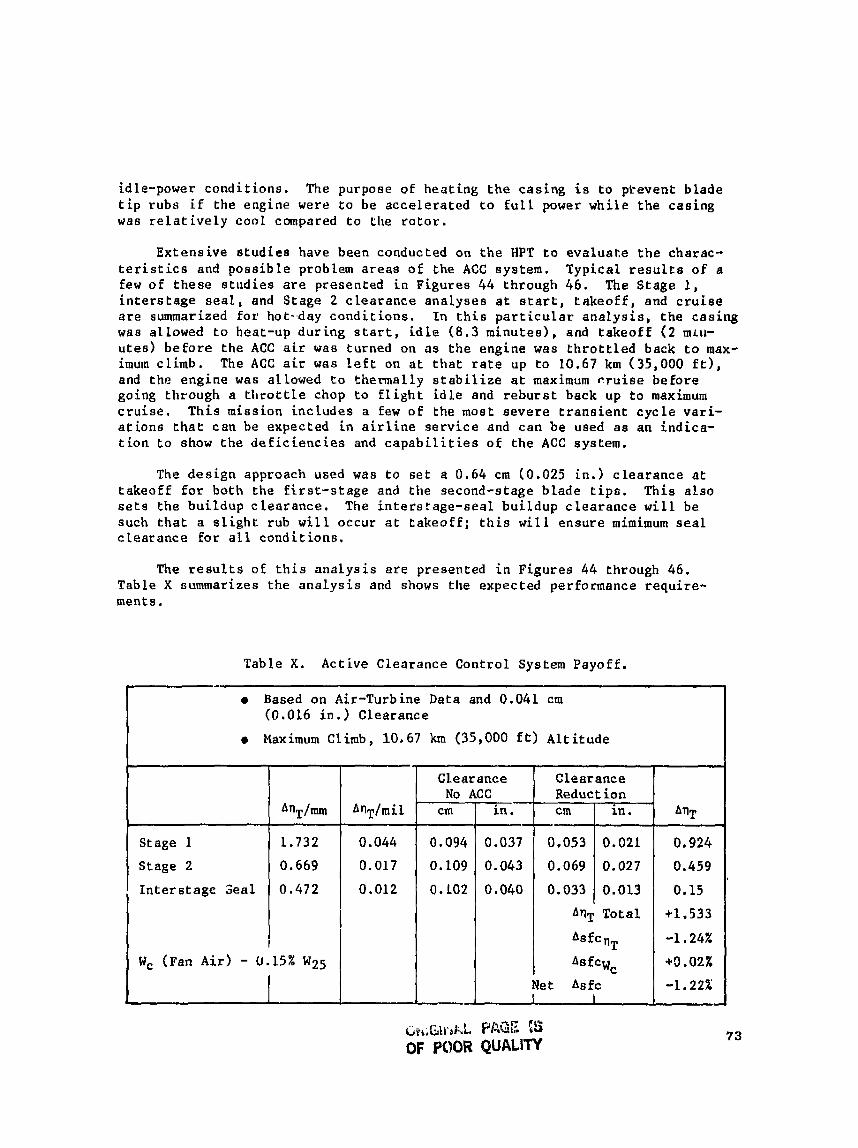
idle-power c o n d i t i o n s . The purpose of h e a t i n g t h e c a s i n g i s t o ptevent b l a d e t i p rubs i f the engine were t o be a c c e l e r a t e d to f u l l power w h i l e the c a s i n g was r e l a t i v e l y coo l compared t o Cl~e r o t o r .
E x t e n s i v e studies have been conducted on t h e HPT t o evaluate t he charac- t e r i s t i c s and p o s s i b l e problem areas of the ACC sys tem. T y p i c a l r e s u l t s of a few of t h e s e s t u d i e s a r e presented i n F igures 44 through 46. The Stage 1 , i n t e r s t a g e s e a l , and S t a g e 2 c l e a r a n c e a n a l y s e s a t s t a r t , t a k e o f f , and c r u i s e a r e summarized for hot-.day c o n d i t i o n s . I n t h i s p a r t i c u l a r analysis, the casing was allowed t o heat-up d u r i n g s t a r t , i d l e (8.3 m i n u t e s ) , and t a k e o f f ( 2 mLu- utes) b e f o r e the ACC air was turned on a s t h e eng ine was t h r o t t l e d back t o max- imum cl imb. The ACC a i r was l e f t on a t t h a t r a t e up to 10.67 km (35,000 E t ) , and t h e e n g i n e was allowed t o the rmal ly s t a b i l i z e a t maximum c r u i s e before going th rough a t l ~ r u t t l e chop t o f l i g h t i d l e and r e b u r s t back up to maximum c r u i s e . T h i s miss ion i n c l u d e s a few o f the most s e v e r e t r a n s i e n t cycle vari- a t i o n s that c a n be expected i n a i r l i n e s e r v i c e and c a n be used as an indica- t ion t o show t h e d e f i c i e n c i e s and c a p a b i l i t i e s of the ACC system.
The design approach used was t o s e t a 0.64 cm 10.025 in . ) c l e a r a n c e a t t a k e o f f f o r both t h e f i r s t - s t age and the second-stage b lade t i p s . This a l s o s e t s t h e b u i l d u p c l e a r a n c e . The i n t e r s t a g e - s e a l b u i l d u p c l e a r a n c e w i l l be such t h a t a s l i g h t t u b w i l l occur a t t a k e o f f ; t h i s w i l l ensure mimimum seal c l e a r a n c e for a l l cond i t i ons ,
The r e s u l t s oE t h i s a n a l y s i s a r e presented i n F i g u r e s 44 through 46. Table X oummarizes the a n a l y s i s and shows the expected performance r e q u i r e - ments.
Table X. Act ive Clea rance Cont ro l System Payoff .
+
Based on Air-Turbine Data and 0.041 cm (0,016 i n . ) Clearance
Maximum Climb, 10,67 km (35,000 f t ) A l t i t u d e
Stage 1
Stage 2
L n t e r s t a g e Seal
AnT/m
1,732
0.669
0.472
W, an A i r ) - 0.15% W25
A n T / m i l
0.044
0.017
0.012
I Asfcwc Net Asfc 1 I
*O .OZX
-1.22%
* f l ~
0,924
0 ,459
0.15
+1.533
-1 .24%
Clearance No ACC
Clearance Reduct ion
' cm
0.094
0.109
O.LO2
cm
0,053
0.069
i n ,
0.037
0.043
0.040
in.
0.022
0.027
0.033 0.013 1 A9T Total
AS fc
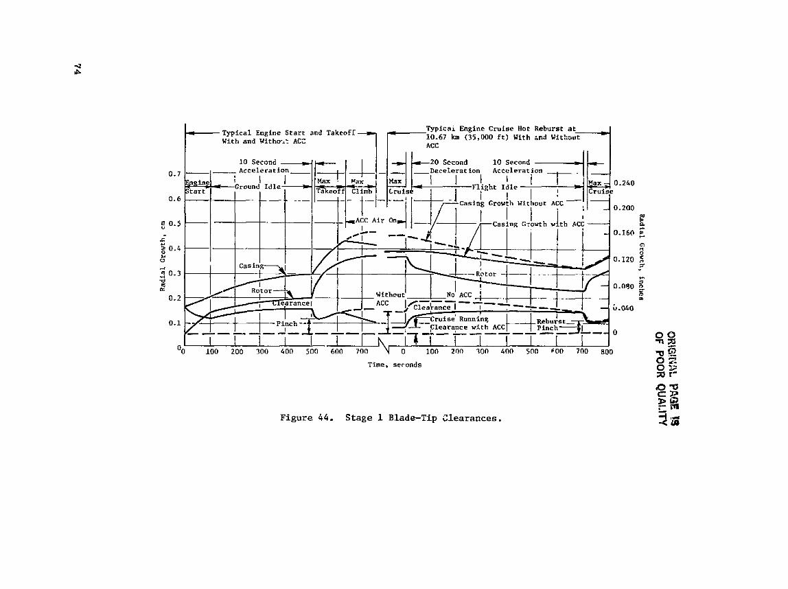
t- Typical Engine Start and Takeofi Typical Engine Cruise Hot Reburst at
With and Withost ACC 7 f 1 0 i 6 7 h (35,000 ft) With m d Withrut 1
Time , seconds
Figure 44. Stage 1 Blade-Tip Clearances.
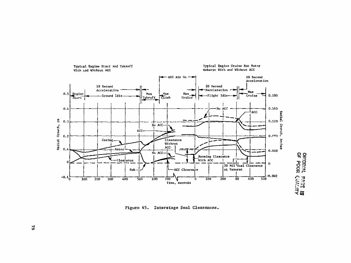
Typical Engine Start and Takeoff With &nd Without ACC
Typical Engine Craise Hot Rotnr Reburst With and Withcut ACC
10 Second bccelerat ion
0.5 Ground Idle Fl i sht Idle 0,180
Tine. 'seconds
Figure 45, Interstage Seal Clearances.

b,.ri;itNA
k PAGE 15
OF PO
OR
QU
ALITY
Rad
ial Growth, in
ches
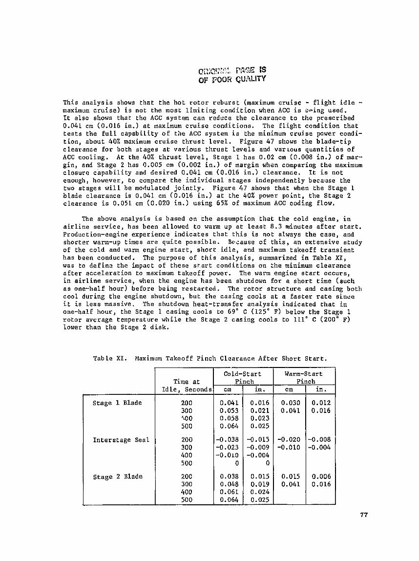
T h i s a n a l y s i s shows t h a t t h e hoL r o t o r r e b u r s t (maximum c r u i s e - f l i g h t i d l e - maximum c r u i s e ) i s not t h e most l i m i t i n g c o n d i t i o n when ACC i s b i n g used, It a l s o shows t h a t the ACC system c a n reduce the c l e a r a n c e t o the p r e s c r i b e d 0.041 cm (0.016 i n . ) a t maximum c r u i s e c o n d i t i o n s . The F l i g h t c o n d i t i o n t h a t t e s t s t h e F u l l c a p a b i l i t y o f Lhe ACC system i s the minimum cruise power condi- tion, about 40% maximum c r u i s e t h r u s t l e v e l . F i g u r e 47 shows the b l a d e - t i p c l e a r a n c e For both s t a g e s a t v a r i o u s t h r u s t l e v e l s and varLous q u a n t i t i e s of ACC coo l ing . A t Lhe 40% t h r u s t Level , S tage 1 has 0.02 cm 10.008 i n . ) o f mar- g i n , and S t a g e 2 has 9.005 cm (0.002 in.) of margin when comparing t h e maximum c l o s u r e c a p a b i l i t y and d e s i r e d 0.041 crn (0.016 i n . ) c l e a r a n c e . It i s n o t enough, however, t o compare the i n d i v i d u a l s t a g e s independent ly because the txo stages w i l l be modulated j o i n t l y . F igure 47 shows t h a t when t h e S tage 1 blade c l e a r a n c e i s 0.041 cm (0.016 i n . ) a t the 40% power p o i n t , t h e S t a g e 2 c l e a r a n c e i s 0.051 cm (0.020 i n . ) u s i n g 65% of maximum ACC coding f low,
The above a n a l y s i s i s based on ehe assumption t h a t t h e co ld engine, i n a i r l i n e s e r v i c e , has been allowed t o warm up a t l e a s t 8.3 minutes a f t e r s t a r t . Production-engine exper ience i n d i c a t e s t h a t this i s no t always the c a s e , and s h o r t e r warm-up times are q u i t e p o s s i b l e . Basause of t h i s , an e x t e n s i v e s tudy o f the c o l d and warm eng ine s t a r t , s h o r t i d l e , and maximum t a k e o f f t r a n s i e n t h a s been conducted. The purpose o f t h i s a n a l y s i s , summarized i n Table XI., was to def i n s the impact o f these s t a r t c o n d i t i o n s on :he minimum c l e a r a n c e a f t e r a c c e l e r a t i o n t o maximum t a k e o f f power. The warm eng ine s t a r t occurs , i n a ir l ine s e r v i c e , when t h e eng ine h a s been shutdown fo r a s h o r t time (such a s one-half hour) be fore being r e s t a r t e d . The r o t o r s t r u c t u r e and c a s i n g both c o o l dur ing t h e engine shutdown, b u t the cas ing c o o l s a t a Eas te r r a t e s i n c e i t is l e s s massive . The shutdown h e a t - t r a n s f e r a n a l y s i s i n d i c a t e d t h a t i n one-half h o u r , Ehe Stage 1 casing c o o l s t o 69" C (125" F) below t h e S tage 1 roLor average temperature w h i l e t h e S t a g e 2 c a s i n g c o o l s t o 111' C (200" F) lower than t h e Stage 2 d i s k .
T a b l e X I , Maximum Takeoff Pinch Clea rance After S h o r t S t a r t .
Stage 1 Blade
I n t e r s t a g e Seal
Stage 2 Blade
Time a t I d l e , Seconds
200 300 400 500
200 300 40 0 500
20C 300 400 500
Warm-Start Pinch
cm
0.030 0 .041
-0.020 -0.010
0.015 0.041
Co ld-S t a r t Pinch
i n .
0.012 0.016
-0.008 -0,004
0.006 0.016
cm
0.041 0.053 0.058 0.064
-0,038 -0.023 - 0 . 0 ~ 0
0
0.038 0.048 0.06L 0.064
in.
0.016 0.021 0.023 0.025
-0.015 -0.009 -0.004
0
0.015 0.019 0 .024 0.025
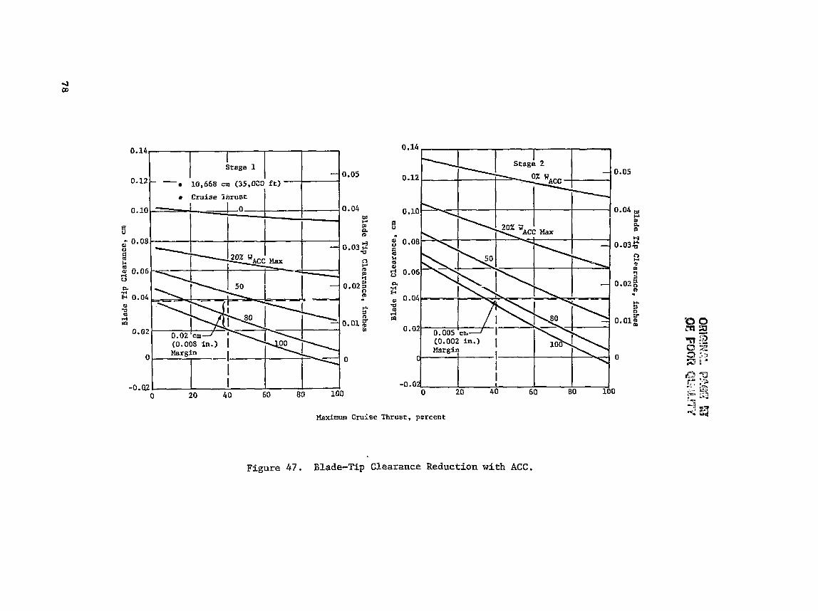
Blade Tip
Cfpernnce,
inches vl
Q
m
I-1 F
I 9
?
? 0
9
a
?
0
0
0
Blad
e Tip
Clearance, inches
In -3
m
N
o
Q
u
o
2
QJ u 9 F.c ld
al l-i U

The r e s u l t s o f the a n a l y s i s i nd ica t e t h a t a s u b s t a n t i a l reduct ion i n the turbine b l ade pinch c learance occurs a t t akeoff on both cold and warm engine s t a r t s when thc engine i s not given s u f f i c i e n t time t o warm up. I f t h e engine acce l from i d l e t o maximum takeoff occurs a f t e r only a 2 t o 3 mi nut^ s t a r t and warm up, t h e pinch c learance can e a s i l y be reduced from the des i red 0.064 cm (0.025 i n . ) t o 0.025 cm (0.010 in.). This could e a s i l y produce a b lade- t ip r u b s ince the pinch w i l l occur i n conjunct ion with high engine maneuver loads and v i b r a t i o n .
I n o rde r t o overcome t h i s p o t e n t i a l problem, a rneans of hea t ing the casing a f t e r s t a r t has been devised. The casing-heating scheme i s accomplished by impinging 0.3% of compressor-discharge a i r on the out s i d e of the cas ing during the i d l e power condit ion f o r 200 seconds. After 200 seconds of cas ing hea t ing , a valve would t u r n the warm compressor-discharge a i r o f f , and t h e va lve would remain closed u n t i l t he engine bad been shutdown f o r a t l e a s t 25 minutes. I f an accel t o maximum takeoff occurred while the casing hea t ing valve was open, i t would remain open f o r 30 seconds a f t e r reaching f u l l power. There i s no advantage i n continuing t o h e a t the cas ing beyond t h e 30-second po in t since the c learance pinch has a l r eady occurred; continued hea t ing of the c a s h g would r e s u l t i n ex t r a power l o s s from the compressor-discharge a i r being taken from the cyc l e and the excess c learances i n the turbine. Under normal engine operat ion, the casing-heating va lve would open j u s t a f t e r the engine achieved i d l e rpm and would remain open f o r 200 seconds. The va lve would then be shut f o r the r e s t o f the engine mission. This would have v i r t u a l l y no i m p a c ~ on engine cyc le performance and would y i e l d s i g n i f i c a n t improvement iq pinch clearances during takeoff . Table XI1 presents the pinch c learances f o r cold and warm engine s t a r t s with ex t e rna l casing haa t ing f o r 200 seconds o r 30 seconds a f t e r accel t o f u l l power, whichever occurred f i r s t .
The d a t a from Table X I show t h a t the warm engine s t a r t / a h o r t idle/maxituum takeoff cycle produces the most l imi t ing pinch during t akeo f f . The improve- ment t ha t can be achieved with the casing-heating scheme becomes evident when a comparison i s made between the two conf igura t ions . For the 200-second s t a r t / i d l e , t h e r e i s a 0.023 cm (0.009 i n . ) increase i n t he pinch c learance f o r both the f i r s t - and second-stage blade t i p s and a 0.005 c m (0.002 i n . ) increase f o r t he i n t e r s t a g e seal, during t akeo f f . This casing-heating sys tem s t i l l does no t g e t the minimum tu rb ine pinch claarnnce back t o the des i r ed 0.64 cm (0.025 i n . ) during maximum takeoff . The minimum pinch c l ea rance i s now 0.048 cm (0.019 i n . ) and 0.038 crn (0.015 in . ) on the f i r s t and second s tages , r e spec t ive ly , with t h e casing-heating scheme. This i nd ica t e s t h a t i t may be necessary t o increase the buildup c learances if 0 .64 cm (0.025 i n . ) i s t r u l y requi red a t maximum takeof f . Since t h i s ana lys i s i s completely ana ly t i - c a i and only has hea t - t r ans fe r ana lys is r a c t i c e from o t h e r engines fac tored i n , i t is necessary t o d e f i n e s p e c i f i c Eg t u rb ine thermal c h a r a c t e r i s t i c s before the op thum FPS ACC can be c l e a r l j def ined. The casing-heating system i s being incorporated i n t o the I C I S engine. This w i l l a l low a complete evalu- - . Lon of t he ACC both wi th and without the casing-heating system. A t r u e systzm eva lua t ion can then be made to d e f i n e the need f o r the heat ing system i n the FPS,
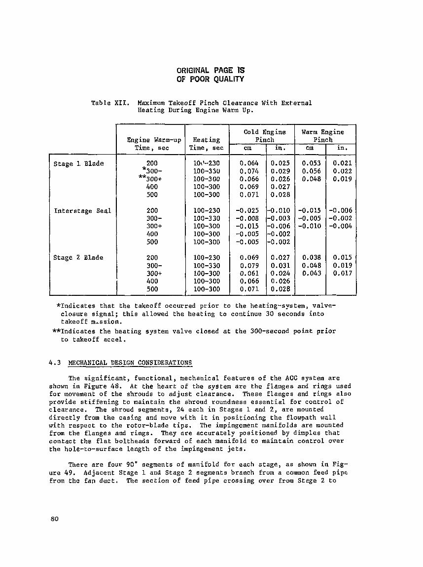
ORIGINAL PAGE IS OF POOR QUALITY
Table XII. Maximum Takeof f Pinch Clea rance With E x t e r n a l Heating During Engine Warm Up.
* I n d i c a t e s t h a t t h e t akeof f occur red p r i o r t o the heat ing-system, valve- c l o s u r e signal; this allowed t h e h e a t i n g t o con t inue 30 seconds i n t o t akeof f mission.
**Indicates the h e a t i n g system v a l v e c losed a t t h e 300-second p o i n t prior t o takeoff accel .
Stage 1 Blade
In t e r s t age Seal
Stage 2 Blade
4.3 MECHANICAL DESIGN CONSIDERATIONS
The s i g n i f i c a n t , f u n c t i o n a l , mechanical f e a t u r e s o f t h e ACC system are shown in Figure 48, A t the heart of t h e system a re t h e Flanges and rings used for movement o f t h e shrouds t o a d j u s t c l e a r a n c e . These f l a n g e s and rings a l s o p rov ide s t i f f e n i n g t o m a i n t a i n t h e shroud roundness e s s e n t i a l f o r control of clearance. The shroud segments, 24 each i n S t a g e s 1 and 2 , are mounted directly from the cas ing and move wi th i t i n p o s i t i o n i n g Lhe f lowpath wall w i t h r e s p e c t t o t h e ro to r -b lade t i p s . The impingement mani fo lds are mounted from t h e flanges and r i n g s , They a r e a c c u r a t e l y pos i t ioned by dimples t h a t c o n t a c t the f l a t bo l theads forward of each manifold t o m a i n t a i n c o n t r o l o v e r t h e hole- to-surface Length o f t h e impingement j e t s .
-
Engine Warm-up Time, s e c
200 *300- **300* 400 500
200 300- 3004- 400 500
200 300- 300+ 400 500
There a r e Four 90" segments o f manifold for each stage, a s shown i n Fig- ure 4 9 . Adjacent S tage 1 and Stage 2 segments branch from a common feed pipe. from the ~ R P d u c t . The s e c t i o n of feed p ipe c r o s s i n g over from Stege 2 t o
Heating Time, aec
lot\-230 100-39U 100-3 00 100-300 100-300
100-230 100-330 100-300 100-300 1.00-300
100-230 100-330 100-300 100-300 100-300
Cold Engine Warm Engine Pinch Pinch
cm
0.064 0.074 0.066 0.069 0.071
-0.025 -0.008 -0.015 -0,005 -0.005
0.069 0.079 0.061 0.066 0.071
in . cm in.
0.025 0.053 0.021 0.029 0.056 0.022 0.026 0.048 0,019 0.027 0.028
-0.010 -0,015 -0.006 -0.003 -0.006 -0.002 -0.002
0.027 0.031 0.324 0.026 0.028

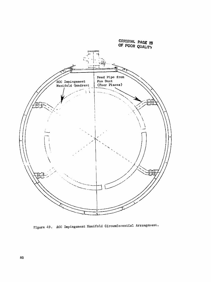
ORlGINAL PAGE 1s OF POOR QUALltt
F i g u r e 49, ACC Impingement Manifold Circcmferentibl Arrangen.ent,
Stage 1 h a s a s l i p j o i n t t o accommodate d i f f e r e n t i a l axia l growth between the c o o l p ipe and the > o t t e r c a s i n g .
The HPT c a s i n g s (forward and a f t ) c o n t a i n t h e c o n t r o l r i n g s . I n t e r n a l l y , t h e c a s i n g s a re in f luenced con t inuous ly by a i r a t t h r e e d i f f e r e n t temperature and pressure l e v e l s : compressor d i scharge , compresRor seventh-e tcge b l e e d , and compressor f i f t h - - s t a g e b leed . They a r e a l s o acted on e x t e r n a l l y dur ing A C C o p e r a t i o n by fan-a i r impingement. The d e p t h and c r o s s - s e c t i o n a l d i s t r i - b u t i o n s of the f l ange s e c t i o n s and t h e convec t ion on t h e s u r f a c e s of t h e s e f l a n g e s have been balanced t o produce synchronized movement o f t h e flanges and m a i n t a i n an a x i a l i y uniform c l e a r a n c e between t h e shroud and b l a d e t i p a t each s t a g e . Axia l t i l t o f the S tage 2 nozz le segments, suppor ted between t h e Stage 1 a f t and S t a g e 2 forward r i n g s , i s a l s o c o n t r o l l e d by this ba lance .
P o t e n t i a l t r a n s i e n t c l e a r a n c e changes a r e l i s t e d i n Table XI11 for the moat c r i t i c a l f l i g h t c o n d i t i o n s . The most s e v e r e t r a n s i e n t c l e a r a n c e reduc- t i o n is i n t h e v e r t i c a l p l a n e , and the i m p l i c a t i o n s o f t h i s a r e explored f u r - t h e r i n Tab le X I V . C l o s u r e s from bending of r o t o r and s t a t i c s t r u c t u r e s due t o maneuver loads ("g" and gyro) a r e combined s t a t i s t i c a l l y ( r o o t sum square , RSS), and a l l o t h e r c l o s u r e v a l u e s a re combined a r i t h m e t i c a l l y t o a r r i v e a t probable n e t va lues o f -0.032 cm (-0.0126 i n . ) and -0.050 cm (-0.0195 i n . ) , shown For 12:OO and 6:00 o ' c l o c k , It i s assumed, a s a l i m i t , t h a t 411 wear would come oEE the b l a d e s i n case oE r u b s . ThereEore, any rub-caused c l e a r - ance i n c r e a s e would be c a r r i e d around the annulus i n t h e form of shor tened b lades r a t h e r than remaining l o c a l i z e d i n the form of a l o c a l d e p r e s s i o n i n t h e sh rouds . On c h i s b a s i s , t h e minimum c l e a r a n c e t h a t could be mainta ined under t h e most severe c l o s u r e c o n d i t i o n s would b e 0.041 cm (0.016 i n . ) aver- age w i t h 0,032 cm (0 .0126 i n . ) a t 12:OO o 'clock and 0.050 cm (0.0195 in . ) a t 6:00 o ' c l o c k . T h i s is achieved by o E f s e t t i n g the shroud c e n t e r l i n e by 0.010 cm (0.004 i n . ) v e r t i c a l l y , r e l a t i v e t o the r o t o r c e n t e r l i n e .
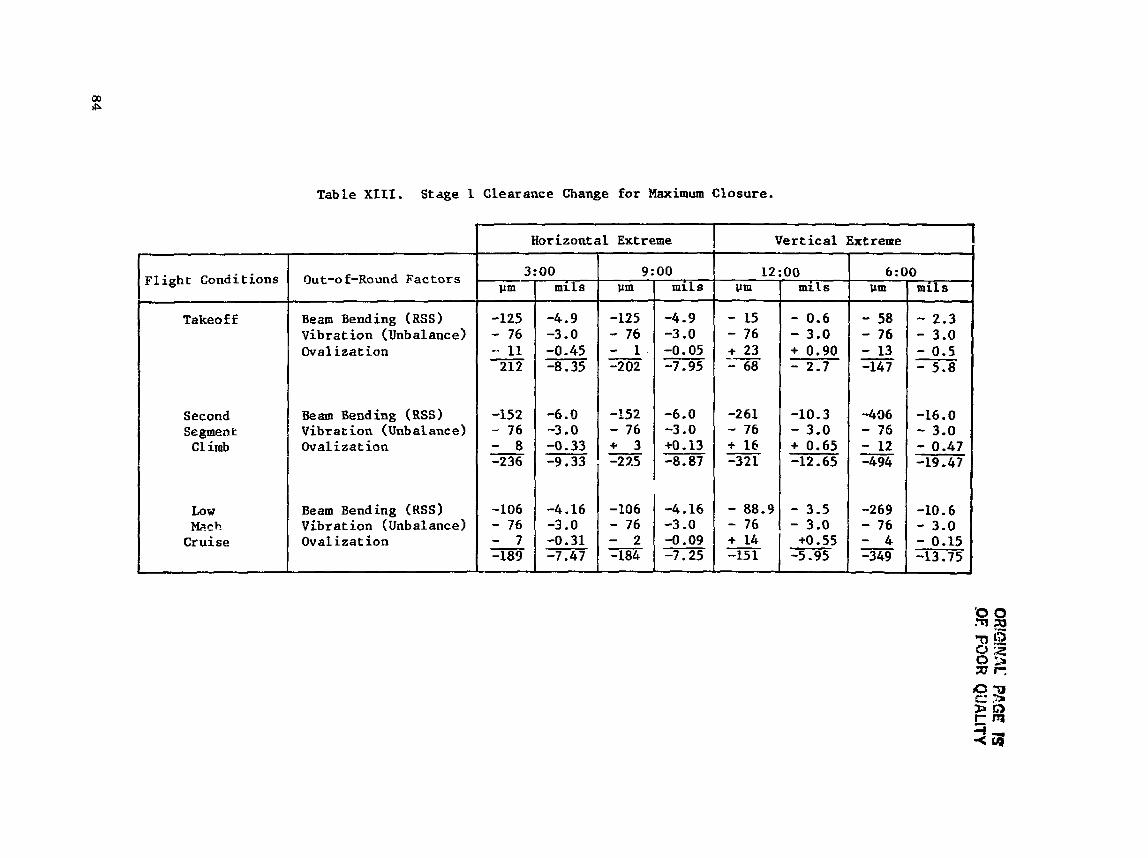
h r-
VSVl
m T???
Cis
57
rD
O?
-tr-
z 9)
C1 W
K
W.
d
a
L) 4
U
J P)
a Q
b
LI
X
W
rl m W
e: 0 N
.d b
&
e bD 4
,-I
R
-
I.
..
mm
om
d
0
11
11
I
I lr;
0
G 0
0
,+ 4 a
r'
-2 0
rD
OQ
\lc
.... ""0"
I1
+1
0 0
QI
m
mow?
. . . omow
r(
11
41
VI
+
rlS
%n
rc
d**d
m
a r- dl3
ll
+l
U1 4
. E
0
0
*. rn
tcl r- \O
m
ul
lnV
I oorc
-roo
Ql
OO
h
r4
WO
CJ
. . .I .
. . .I" . .
. -$mob
II
II
'f3
? I
u'
'7
(D
rl
5
bn m
rrl C
rl moem
OC
??
"
;?+:
+++Ii "4 I
fI
I d"alb
11
11
2~~1: 5
rmp
9w
bfr
I
Ii
I
tI
I
5"
Il
l1
V)
CI 0
+.'
:
fG
* e 3
3 I
h
n
n
a
w 0)
0
0
tl -
e
- a - E
m
a
vl
m v3
rd
2G
z 2
U3 d
x
a
UP
'-'a F
-a
E
r: M
P
boa
bo
s
E-
e .r
( 0
0-
d
a
- D
0
0
rj~
:.r
l
II c
:-d
a c
-A
i.9; $
3 :
aw
rl
e o
u
a
C9
UN
0
mu
t4
I
m *rl
:*: 8
wr
l
Q
CP
3
rn 3
cll 0 0
.PI V
'#
-I 71 e
45 sl
w
Id
dP
a
0
g 83
f!
u)
0
Y
H
VJ 0)
U
: 2G

Table IIV. Blade-Tip/Shroud Clearance.
I
Clearance
Lo w-Mac h Cruise
m
0.406
0.305
+0.015 -0.005
-0.089 -0.269
-0.149 -L 151
0 0.046
Maxim1.m Clear- ance and
High-Mach Cruise
I
I Maximum
in.
0.016
0.012
+0.0006 -0.0002
-0.0035 -0.0106
-0.0059 -0.0138
0 0.0018
um
0.406
in.
0.016
m UI
Gold
Tolerance Stack
Min. Clearance
Vibrat ion
Out of Round, 12:OO 6 : 00
Beam Bending, 12 : 00 ("g," Gyro, Thrust, 6: 00 Nacelle Air)
Tot a1 Closure, 12 : 00 6 : 00
Max. Interference, L2:00 6:OO
O f f set
Max. Rub, 12:00 ant; 6:30
Local Clearance with Rub
nm
1.24
1.14
Takeoff
in.
0.049
0.045
mn
0.889
*0,102 mm (0.004 in.)
I 0
0 0
0 0
in.
0.035
0.787 0.031 I k0.076 ram
0.305
M.023 -0.013
4.015 -0.058
0.012
+0.0009 -0.0005
-0.0006 -0.0023
-0.0126 -0.0195
0.0006 0,0075
0.0040
0.0035
0.016
-0.114 -0.139
(0.003 in.)
+0.018 -0.013
-0.262 -0.406
-0.0045; -0.320
+0.0007 -0.0005
4.0103 -0.0160
-0.0055
0 0
-0.495
0.015 0.190
0.102
0.089
0.406
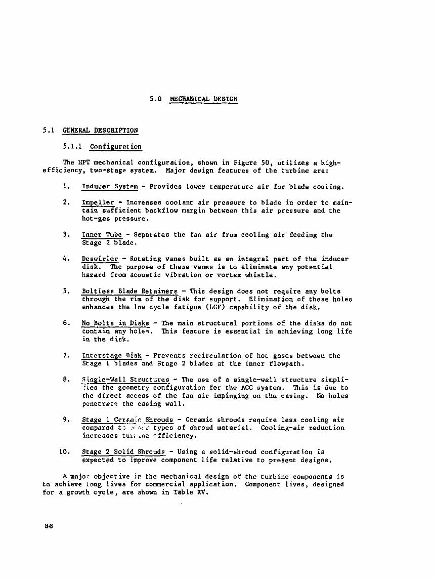
5.0 MECHANICAL DESIGN -
5.1 GENERAL DESCRIPTION
5.1.1 Configurat ion
The HPT mechanical con f igu ra i ion , shown i n Figure 50, u t i l i z e s a high- e f f i c i e n c y , two-stage system. Major design f ea tu re s of the turb ine a re :
1 , Inducer System - Provides lower temperature a i r f o r blade cool ing.
2 , Impel le r - Increases coolant a i r pressure t o blade i n order t o main- t a in s u f f i c i e n t backflow margin between t h i s s i r pressure and the hot-gae pressure.
3. Inner Tube - Separates t h e fan a i r from cool ing a i r feeding the Stage 2 blade.
4 , Deswirler - Rotating vanes buiLt as an i n t e g r a l p a r t of the inducer d i s k , The purpoee of t hese vanes i s t o e l imina te any po ten t id l . hazard from acoust ic v i b r a t i o n o r vortex whistle.
5 , B o l t l e s s Blade Re ta ine r s - This design does not r equ i r e any b o l t s through t h e r i m of t h e d i s k f o r support. El iminat ion of t hese ho le s enhances the low cycle f a t i gue (LcF) c a p a b i l i t y of t h e disk,
6 . No Bo l t s i n Disks - The main s t r u c t u r a l por t ions of the d iaks do not contain any holes . This f ea tu re is e s s e n t i a l i n achieving long l i f e i n t h e disk.
7. I n t e r s t a g e Disk - Prevents r e c i r c u l a t i o n of hot gases between the Stage 1 blades and Stage 2 blades a t t he inner flowpath,
8. .. Single-Wall . - Structures_ - The use of a single-wall s t r u c t u r e simpli- -. :.ces the geometry conf igura t ion for t h e ACC system. This i s ciue t o the d i r e c t access of t he fan a i r impinging on the casing. No holes penetrate the casing wa l l .
9 , Stage 1 Cer6m;r ,- - . Shrouds - Ceramic shrouds r e q u i r e l e s s cool ing a i r compared t ; .I G < r types o f shroud mater ia l . Cooling-air reduct ion increases t u ~ ; ~ n e e f f i c i e n c y .
10. Stage 2 Sol id Shrouds - Using a solid-shroud conPigurati.on is expected t o improve component l i f e r e l a t i v e t o present designs,
A major ob jec t ive i n the mechanical design of the t u r b i n e components is t o achieve long l i v e s for commercial app l i ca t ion , Component l i v e s , designed f o r a growth c y c l e , are shown i n Table XV.


Table XV. Component Design Lives .
Flowpath components ( b l a d e s , vanes , b l a d e r e t a i n e r s , i n t e r s t a g e disk) a r e designed for 18,000 h o u r s w i t h r e p a i r s p e r m i s s i b l e a f t e r t h e f i r s t 9000 hours of engine o p e r a t i o n .
Flowpath components/ Blade Retainer
Disks, S h a f t e / S e a l Disk
The t jpe of r e p a i r s for t h e s e components a r e as f o l l o w s :
S t a g e 1 and 2 Blades
S e r v i c e
Flight Hrs
9,000
18,000
Repair would be performed i n t he fo l lowing areas:
Blade t i p - Weld b u i l d u p the t i p l o c a l l y . For abnormal ly worn t i p s , t he t i p is removed and r e p l a c e d u s i n g A c t i v a t e d D i f f u s i o n Bonding (WB), The ME! p r o c e s s was developed f o r t h e 3 3 9 and i s p r e s e n t l y being used by GE for r e p a i r i n g HP t u r b i n e b l a d e s f o r o t h e r engines, e s p e c i a l l y for c o m e r - c i a 1 use.
I n s t a l l e d
F l i g h t Cycles
9,000
18,000
P l a t f o r m Cracks - Normally c r a c k s i n t h e p l a t f o r m would appear a l o n g t h e edges, These l o c a t i o n s ace not cone ide red t o be highly s t r e s s e d (mechan- i c a l l y ) and can be r e p a i r e d u s i n g the Activated Diffusion Healing (ADH). The d i f f e r e n c e between ADB and ADH is t h a t ADH is l i m i t e d t o c r a c k r e p a i r s n o t exceeding approximate ly 0,1016 cm (0.04 i n c h ) , and there are no missing p i e c e s within t h e a r e a t o be r e p a i r e d .
PVD Coating - The PVD c o a t i n g could be s t r i p p e d and a new c o a t i n g a p p l i e d .
Tot a1 Service L i f e With Repair
Stage 1 and 2 Blade R e t a i n e r s
F l i g h t s Hrs - 18,000
36,000
Repair weld would be l i m i t e d t o the l a b y r i n t h seal t e e t h . The repair would consist of removing l o c a l l y developed c r a c k s t h a t may appear c l o s e t o the sharp edge s u r f a c e s of the t e e t h . The surrounding area around t h e c r a c k is removed, p o l i s h e d , and zygloed.
F l i g h t Cycles
18,000
36,000 J
A weld b u i l d u p process u s i n g ~ e n ' e 95 f i l l e r m a t e r i e l would be used. The aluminum o x i d e c o a t i n g would be removed by chemical s t r i p p i n g p r i o r t o w e l d i n g . The c o a t i n g would t h e n b e r e a p p l i e d a f t e r X-ray and Zyglo inspec- t i o n s ahow no f u r t h e r c r a c k s .
The above procedure i s an e s t a b l i s h e d and approved p rocess f o r I n c o 718, In the case o f AF115 m a t e r i a l , t h i s r e p a i r p rocess has n o t been f i r m l y estab- l i s h e d , and, t h e r e f o r e , f u r t h e r work would be necessa ry t o a s s u r e complete a p p r o v a l .
In the even of r a b b e t sear, t h e s u r f a c e can be machined L0.0254 c m (0.01 in.) t o 0.0508 cm ( 0 . 0 2 in.)] and a hard m e t a l spray a p p l i e d and ground down t o the o r i g i n a l d imensions .
Stage 1 aitd 2 Disk
Repair would be l i m i t e d t o the f l a n g e b o l t h o l e s , r abbe t s u r f a c e wear, and t h e l o c a l r a d i a l s c a l l o p s l o c a t e d i n t h e f l a n g e s used f o r a i r passagee.
Depending on t h e size oE c r a c k s found, the b o l t h o l e s would be reamed and p o l i s h e d . Th i s would a l s o a p p l y t o t h e Stage 2 forward d i s k arm cool ing-hole passage ,
Forward and A f t S h a f t s
The two-sea l - t ee th arrangement on the HP s h a f t would be r e p a i r e d u s i n g h
s i m i l a r procedure p r e s e n t l y u sed for the CF6-50 eng ine i n t e r s t a g e c a t e n a r y s u p p o r t . If c r a c k s s p p z a r on t h e f l a n g e s , t h e y would be roamed, provided t h e sizes of t h e c r a c k s ara s m a l l ,
In t h e even t of r a b b e t weay, a similar procedure as d e s c r i b e d for t h e b l a d e r e t a i n e r s c a n be used.
Impeller
Repair c o u l d be done on t h e e l l i p t i c a l c o o l i n g passages l o c a t e d above the rabbe t s u p p o r t . These c o o l i n g h o l e s a:. e l l i p t i c a l i n geometry and could be s l i g h t l y i n c r e a s e d i n s i z e , i f necessa ry .
Fnrward Sea l Disk
By s l i g h t i y i n c r e a s i n g h o l e s i z e s , r e p a i r s can b e made f o r thb2 fol lowing:
a Cool ing ho l e pessages
r E l l i p t i c a l b o l t h o l e s ( l i m i t e d s i z e o n l y )
I n n e r f lange b o l t h o l e s ( f a s t e n s t h e i n n e r tube t o t h i ; f l a n g e ) ,
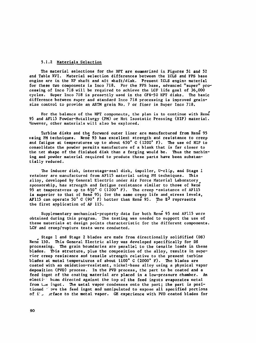
5.1.2 Mate t ia le Se l ec t ion
The mate r i a l s e l ec t ions f o r the HPT a r e sumar i zed i n Figures 51 and 52 and Table XVI. Material s e l e c t i o n d i f f e r ences between the ICLS and FPS base engine a re i n the HP s h a f t and a f t sha f t / d i sk . Present ICLS engine mater ia l f o r these two components i s Inco 718. For t h e FPS base, advanced "supert' pro- cessing of Inco 718 w i l l be requi red t o achieve the LCF l i f e goa l of 36,000 cyc les . Super Inco 718 i s prese7tl.y used i n the CF6-50 HPT d i sks . The basic d i f f e r ence between euper and s tandard Inco 718 processing is improved grain- s i z e control t o provide an ASTM gra in No, 7 or f i n e r in Super Inco 718.
For the balance of the HPT componet~ta, t he plan i s to cont inue with ~ e n g 95 and AF115 Powder-Metallurgy (PM) o r Hot I s o s t a t i c Pressing (HIP) mater ia l . qowever, o the r ma te r i a l s w i l l a l s o be explored,
Turbine d inks and t h e forward ou te r l i n e r a r e manufactured from ~ e d 95 us ing PM techniques. Rene 95 has exce l l en t s t r eng th and r e s i s t a n c e t o creep and fat igue a t temperatures up t o about 650' C (1200' F), ' h e use of HIP t o consol idate t h e powder permits manufacture of a blank t h a t i s f a r c l o s e r t o the rAet shape of the f in i shed d i s k than a forg ing would be. Thus the machin- ing and powder mater ia l requi red t o produce these p a r t s have been substan- t i a l l y reduced.
The inducer d i sk , in te rs tage- -sea l d i sk , impal le r , U-clip, and Stage 1 r e t a i n e r a r e manufactured from AF115 mater ia l using PI1 techniques, This a , l l o y , developed by General E l e c t r i c under A i r Force Material Laboratory, sponsorship, has s t rength and f a t i g u e r e s i s t a n c e s imi l a r t o those of Hene 95 a t temperatures up t o 650' C (1200' F ) . The c reep - e s i s t ance of AF115 ie auperior t o t h a t of Rene 95; f o r the same c r y p l i f e and s t r e s s l e v e l s , AFllS can ope ra t e 50' C (90' F) h o t t e r than Kene 95. The E~ represents t he f i r s t app l i ca t ion of AF 115.
Supplementary mechanical-property da t a f o r both ~ e n ; 95 and AFL15 were obtained during t h i s program. The t e s t i n g was needed t o support the use of these ma te r i a l s a t design po in t s c h a r a c t e r i s t i c f o r the d i f f e r e n t components. LCF and creep/rupture t e s t s were conducted.
Stage 1 and Stage 2 b lades a r e made from d i r e c t i o n a l l y s o l i d i f i e d (DS) ~ e n g 150. Thie General E l e c t r i c a l l o y was developed s p e c i f i c a l l y f o r DS processing. The g ra in boundaries a r e p a r a l l e l t o the t e n s i l e loads i n these b lades . This s t r u c t u r e , p lus t h e composition of the a l l oy , r e s u l t s i n supe- r i o r creep r e s i s t a n c e and t e n s i l e s t r eng th r e l a t i v e t o the present tu rb ine b lades a t metal temperhturca o f about 11004 C (2000" F) . The blades a r e coated with an oxidat ion- res i s tan t , nickel-base a1 loy using a physical vapor depos i t ion (PVD) process. In t h e PVD process , t he par t t o be coated and a feed ingot of t h e coat ing m a t e r i a l are placed i n a low-pressure chamber. An e l e c c i r - beam di rec ted aga ins t the top of t h e feed ingots evaporates metal from t.'e iqgot . The metal vapor condenses onto the pa r t ; t he pa r t is psi- t ioned -' w e t h e feed ingot and manipulated t o expose a l l epecif ied por t ions of i r , ~ r f a c e t o the metal vapor. GE experience with PVD coated blades f o r
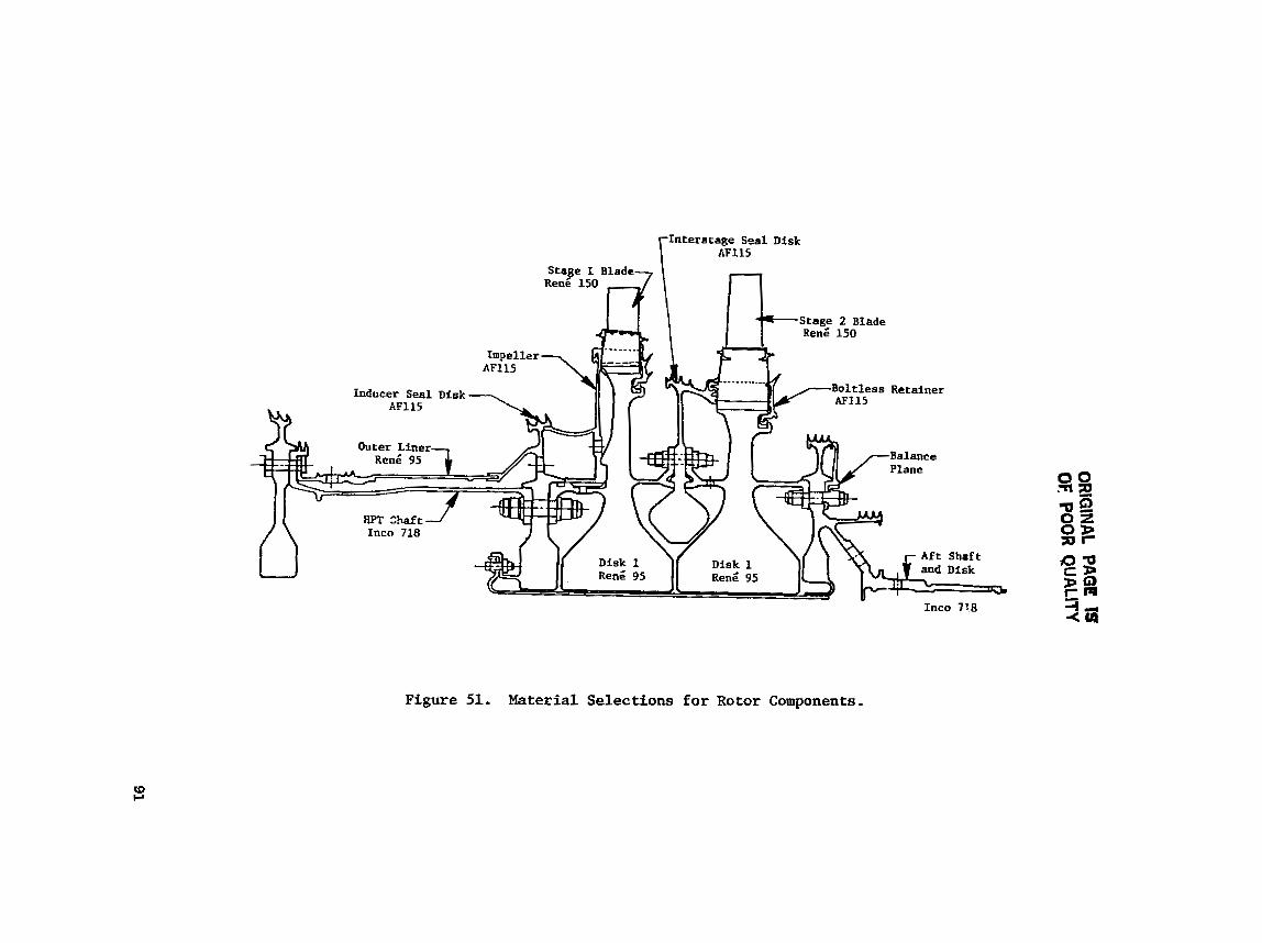
Interscage Seal Dfsk AF115
Inco 718
Figure 51. Material Selections for Rotor Components.
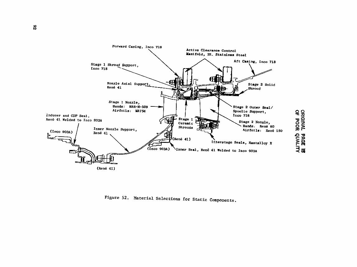
OR
IGIN
AL PAGE IS
OF PC)OR
QU
ALITY

ORfGfNAL PAGE IS OF POOR QUALITY
Table XVI. Rotor and Stator Materials.
Part
Stage I Vanes
S t a g e 1 Bands
S t a g e 1 and 2 Blades
Stage 1 and 2 Disks
S t ; l ~ e 1 Shrouds
S t a g e 2 Shrouds
Srage 2 Nozzle and Shroud Support
Outer Cas ing
S t a g e ! ~ e t a i n e r / S e a l (Fwd. and A f t )
I n t e r s t a g e S e a l Disk and s p a c e / H e t a i n e r
S tage 1 I n n e r Nozzle ?upport
Slage 2 Val~e
S t a ~ e 2 Vane Band
Stage 2 I n n e r s t a g e Seal
tmpel le r
Inner S h i e l d
Srage 2 A f t R e t a i n e r
Forward S h a f t
Fwd. O u t e r Liner
Inducer /See l Disk
A f t S h a f t l D i s k
lnducer/CDP Seal
Stage I I n n e r S e a l
M a t e r i a l
MA7 54
MAR-M-509
~ e n i 15D
en; 95
Ceramic ( Z i r c o n i a / Y t t r i a )
Rcn; 7 7 ( S o l i d )
Inco 718
Incn 718
AF115
I n c a 718
en; 95
AFl15
Inco 718
Inco 9 0 3 ~ / ~ e n G 41
Form
E
C
C , DS
Ptl ---
C
F
F
PM
PM
F
C
C
F, HC
Ph
F
PM
I F
m F
: F, S
F I I I
I F/S HC I I I F/ H/C
Heason far S e l e c t i o n - - -
Creep , Burnout M a r g ~ n , LLF
Rupture , C ~ s t ; Y . S .
Kupture, LCF
T e n s i l e ( B u r s t )
High Temp >1370' C (2500' t C a p a b i l i t y , Eros ion
Cost
Med Temp S t r e n g t h , T e n s i l e S t r e n g t h
Med Temp S t r e n g t h , T e n s i l e S t r e n g t h
704-760. c (13~0-1400 ' F) Creep , LCF
704-740' C ( 1JOO-1400' k ) Creep, LCF
Rupture Vs, Inco 718, Tenbp.
LCF, Rupture
Rupture and C a s t a b i l i t y
Temperature
Temp, LCF, Rupture
538-649' C 11000-12~0' F) T e n s i l e
Creep , Hupture S t r e n g t h
5J8-649' C ( 1 0 0 ~ - 1 2 0 0 ' b ) Tensi le , LCt*
LCF, Rupture
Rupture , LCF, Temp.
538-649" C ( LOOO-1200' F) T e n s i l e , LCF
Low C o e f f , o f Exansion for C l e a r a n c e Matching
Temp, LCF, C o e f f . o f Expanfiion
E - E x t r u s i o n C - C a s t DS - D i r e c t i o n a l l y S o l i d i f i e d PM - Powder Meta l lu rgy F - Forging
long-time usage h a s been the r ecen t ly completed t e s t i n g accomplished i n the CF6-50 Engine 455-508 Buildup 21. Thie engine was t e a t run f o r 1000 "C" cyc l e s . Some of the CF6-50 engine, Stage 1 HPT blades (Itens 150 ma te r i a l ) were coated with P V D . These blades were a modif icat ion of the s tandard HP b lades . The modif ica t ion e s sen t i a l . l y coneis ted of reducing t h e blade cool- ing flows. This was accomplished by d e l e t i n g the center row of leading-edge h o l e s and also t h e cool ing holes on the pressure s i d e , midchord. The e f f e c t of t h e reduct ion i n cool ing holes r e s u l t e d i n flows being lowered from pre- s e n t 3.4% to 2.8%. Predicted leading-edge temperature f o r the PVD coated b l ades was 1110' C (2030' F).
Test Evaluat ion - A l l HP t u rb ina blades went through the f u l l 1000 t'Ct' c y c l e s t e s t . Appear-
ance of the ~ e n s 150, PVD coated b ladee , a f t e r completion of the t e s t wae s imi la r to tlie standard-production, ~ e n 6 80, Codep-coated blades i n s p i t e of t h e 56" C (100' F) h o t t e r blade temperatures of tile ~ e n 6 150 blades,
The 1000 "C" cyc les CF6-50 engine t e s t s s imulate the b lade l i f e f o r t h e s tandard CF6-50 blades. The E~ blade, 9000 hours between coa t ing r e p a i r , i s the re fo re a t t a i n a b l e . Another f a c t o r t h a t enhances ob ta in ing the 9000 hours i s that t he maximum sur face temperature f o r t h e E~ Stage 1 blade is 1074' C (1965' F) versus 1110" C (2030" F) f o r the modified CF6-50 blade. The d i f f e r e n c e of 36' C (65" F) i s s i g n i f i c a n t i n terms of coating l i f e improve- ment i n high-temperature opera t ing range.
Based on the CF6-50 engine experience with the modified Stage 1 blade ( ~ e n 6 150 coated w i t h PVD) i t is expected that the I33 HP b lade can be designed with 9000 hours of opera t ion p r i o r t o recoa t ing .
The coat ing spec i f i ed f o r t he ICLS engine is a s ingle- layer , nickel-base c o a t i n g applied by the PVD process . This process has been found t o provide p ro t ec t ion aga ins t oxidat ion. The FPS engine w i l l have a two-cornpnnent coat- ing system: a nickel-base PVD coa t ing (of a d i f f e r e n t chemical composition) £01 lowed by pack aluminiding . This two-component system provides s l i g h t l y b e t t e r oxidat ion r e s i s t a n c e but r e q u i r e s two sepa ra t e manufacturing opera t ions .
The Stage 1 nozzle i s assembled from vanes made of MA-754 mater ia l and from inner and o u t e r bands made of MAR-M-509 mate r i a l , The l a t t e r i s a con- ven t iona l , cobalt-base, c a s t i n g a l l o y and has good s t r eng th t o r e s i s t d i s t o r - t i o n a t metal temperatures of about 1040' C (1900' F). MA-754 i s an oxide- d i spe r s ion s t rengthened ( O D s ) a l l o y manufactured by a mechanical a l l oy ing pro- c e s s ; the c r y s t a l s t r u c t u r e i s s t rong ly t ex tu red , As a r e s u l t , mechanical and phys ica l proper t ies vary considerably, depending on the o r i e n t a t i o n of t h e t e s t specimens r e l a t i v e t o the bar from which they were made. The textured s t ruc- t u r e i s optimized i n t h e spanwise d i r e c t i o n t o provide improved thermal-fatigue p r o p e r t i e s . MA-754 hss e x c e l l e n t ox ida t ion r e s i s t a n c e ; i t can be used a t tenr p e r a t u r e s above 1100" C (2000" F) without su r f ace p ro t ec t ion . The a i r f o i l s and bands a r e conveniently assembled by brazing.
The E~ Stage 1 nozzle is a f a b r i c a t i o n involving a brazed jo in t a t t he airfoi l - to-band i n t e r f a c e . The E~ braze a l l o y and the a i r f o i l mater ia l a r e

the same a s t h a t used on S t a g e 1 n o z z l e s o f o t h e r General E l e c t r i c development and p roduc t ion engines. The i n t e g r i t y o f these j o i n t s h a s been s u c c e s s f u l l y demonstrated i n endurance-type eng ine t e s t s .
I n e x i a t i n g General E l e c t r i c eng ines c o n t a i n i n g Stage 1 n o z z l e s processed a s a f a b r i c a t e d des ign , l o c a l c racks a f t e r e x t e n s i v e t e s t i n g s seem t o i n i t i a t e from the t r a i l i n g - e d g e " inner vane" and p r e s s u r e - s i d e r e g i o n s . These c r a c k s s t a r t a t t h e a i r fo i l - to -band i n t e r f a c e , t r a v e r s e a c r o s s the braze j o i n t , and cont inue a l o n g the band s u r f a c e .
These n o z z l e s con t inue t o be used wi thou t any r e p a i r p rocess ing . Only i f the inner-band f l ange s u p p o r t shows y i e l d i n g !seen through phys ica l a x i a l fLange d i s t o r t i o n ) , or i f c r a c k s appear on t h i s f l a n g e , i s t h e n o z z l e r e t i r e d due t o t h i s c o n d i t i o n .
The Stage 1 shroud i s a composite metal /ceramic p a r t . The backing mace- r i a l i s c a s t from Ren6 7 7 . A thermal-spraying p rocess i s used t o app ly t h e f i n a l coat of y t t r i a - s t a b i l i z e d z i r c o n i a . Adherence of t h e c o a t i n g t o the backing i s enhanced by a mechanical anchor ing s y s t e m . Because t h e ceramic c o a t i n g is an e x c e l l e n t thermal i n s u l a t o r , the amount o f a i r r e q u i r e d t o cool the shroud i s s i g n i f i c a n t l y reduced compared t o p r e s e n t shrouds .
The Stage 2 nozz le is assembled from a i r f o i l s made of DS ~ e n 6 150. The inner and o u t e r bands a r e made from c o n v e n t i o n a l l y c a s t ~ e n k 80. The lat ter a l l o y i s used i n a s i m i l i , a p p l i c a t i o n i n o t h e r eng ines . The c r y s t r a l struc- t u r e of t h e DS Reng 150 vanes i s h i g h l y a n i s o t r o p i c , and t h i s f e a t u r e i s u t i l i z e d t o minimize the ef f e c t e of thermal f a t i g u e on t h e nozz le . I n d i v i d u a l a i r f o i l s a r e coated wi th a n icke l -base , o x i d a t i o n - r e s i s t a n t a l l o y u s i n g a phys ica l vapor-deposi t ion p r o c e s s . (The PVD process is d e s c r i b e d i n greater d e t a i l i n t h e s e c t i o n on b l a d e s . ) A f t e r the nozz le components &re assembled by b raz ing , t h e e n t i r e ?gaernblp i s a luminided u s i n g a pack coating process . Th i s combination of c o a t i n g s can p r o t e c t both vanss and bands for thousands of hours o f s e r v i c e .
The S t a g e 2 shroud is s o l i d R e d 77, and t h e c o n f i g u r a t i o n i s s i m i l a r t o those used i n the F l O l and CF6-80 engines . A c o b a l t m a t e r i a l base c o a t i n g i s app l ied by thermal sp ray t o t h e ~ e n 6 77 backing.
Other components of t h e HPT a r e made from m a t e r i a l s t h a t have been proved i n o t h e r t-ngines. They a r e a b l e t o meet the t empera tu re , load , and environ- mental r equ i rements ,
F r a c t u r e Mechanics Ana lys i s - The LC9 Lives p r e d i c t e d for the v a r i o u s a r e a s o f t h e HPT spool i n t h i s r e p o r t a r e based on conven t iona l -30 LCF d a t a and i n d i c a t e t h e r o t o r d e s i g n l i f e requirements have been m e t . Recent f a c t o r y and f l i g h t - t e s t exper ience , however, i n d i c a t e s t h a t t h e minimum c y c l i c l i f e of as-HIP ~ e n g 95 PM components can b e lower t h a n that p r e d i c t e d by t h i s method. Experience is showing tha t t h i s m a t e r i a l i s s e n s i t i v e t o smal l i n t e r - n a l and s u r f a c e d e f e c t s i n h e r e n t i n the conven t ions1 PM p r o c e s s , These d e f e c t s a c t a s c r a c k i n i t i a t i o n s even i n v i r g i n m a t e r i a l . The reduced c y c l i c l i f e due
t o these i n i t i a t i o n . p o i n t s is more accu ra t e ly predicted us ing fracture-mechan- i c a techniques.
A fracture-mechanice a n a l y s i s of t h e ~3 HPT r o t o r spool , based on an assumed defkct s i z e equivalent t o t h e m i n i m u m de tec t ion l i m i t of ava i l ab l e nondestruct ive t e s t i n g (NDT) methods, i s ;?ow i n process, Lesul t s of t h i s ana lys i s w i l l be presented a t a l a t e r da t e . Proceso modif icat ions or ma te r i a l s u b s t i t u t i o n s w i l l be considered f o r t h e FPS spool conf igura t ion t o ensure component i n t e g r i t y f o r the design c y c l i c l i f e . A s u b s t i t u t e ma te r i a l i s not under cons idera t ion f o r t h e ~3 HPT r o t o r design f o r e i t h e r the current o r follow-on programs. PM ~ e n 6 95 and AF115 marer ia le w i l l continue t o t, used fo r any follow-on ~3 HPT d i s k designs. Work i s cu r r en t ly underway t o incor- pora te processing refinements which w i l l r e s u l t i n improved powder c l ean l i - ness and increased low cyc le f a t i g u e c a p a b i l i t i e s . It i s expected t h a t t he improved powder metal mater ia l s w i l l have euper ior low cyc le f a t i g u e l i f e / f r a c t u r e mechanics c h a r a c t e r i s t i c s f o r advanced tu rb ine designs,
5.1.3 Analy t ica l Methods %
5.1.3.1 Computer Programs
Analysis of the HPT components was conducted us ing numerous computer pro- grams developed by the General E l e c t r i c Company. Table X V I I l ists the names of the va r ious computer programs t h a t were used i n the ana lys i s of the HPT mechanical design. The table a l s o summarizes t h e mechanical c h a r a c t e r i s t i ca which the programs analyze or c a l c u l a t e ,
5.1.3.2 Procedures
Two of t h e programs l i e t e d i n Table XVII were used ex tens ive ly i n the s t r u c t u r a l ana lys i s of t h e HPT. The f i r s t , c a l l e d CLASS-MASS, i s a mathemat- i c a l - s h e l l a n a l y s i s program. I n us ing t h i s program, the r o t o r s t r u c t u r e i s divided i n t o s h e l l elements, These s h e l l elements can be c y l i n d r i c a l ( s h a f t s , e t c , ) , con ica l ( a f t s tub s h a f t ) , o r v e r t i c a l (d i sks , e t c . ) . Axial ly symmetric o r asymmetric ex terna l load can be app l i ed . The second, ca l l ed FINITE, calcu- l a t e s very Localized s t r e s s e s as a rmnd holes, d i s k posts , s l o t s , f i l l e r s , d i sk bores, and other types of geometries where sur face d i s c o n t i n u i t i e s e x i s t .
Boundary condit ions used f o r t h e FINITE model a r e t he r e s u l t i n g loads or de f l ec t ions from t h e CLASS-MASS program. Using FINITE ana lys i s g r e a t l y enhances t h e t r u e l o c a l s t r e s s f i e l d r e l a t i v e t o us ing t e s t da ta from photo- e l a s t i c re ferences , Th is i s because, i n t h e use of FINITE, there e x i s t s a r a d i a l and a c i rcumferent ia l s t r e s s g rad ien t along the hole height ( o r r ad ius ) . T h i s g rad ien t i s due t o speed e f f e c t s , which vary with rad ius , and also due t o t h e r a d i a l temperature v a r i a t i o n .

Table XVII. Analytical Computer Methods.
Conlputer Program
BUCKET CREEP
CLASS-MASS
TWISTED BLADE
MU LT I-HOOK
A n a l y s i s 1
P r e d i c t a Time-Dependent , L o c a l i z e d Values of S t r e s s , S t r a i n , and Creep Damage Due t o Tem- p e r a t u r e and E x t e r n a l Loads . A n a l y s i s Baaed on Beam Theo ry ( P l a i n S e c t i o n a Remain P 1 ane )
S t r e s s and V i b r a t o r y S o l u t i o n s Due t o Axisymmetr ic -Shel l S t r u c t u r e s - Thermal - Mechanica l - Maneuver
Can Also Ana lyze O r t h o t r o p i c S h e l l S t r u c t u r e s
e C e n t r i f u g a l Recovery E f f e c t s
V i b r a t o r y C h a r a c t e r i s t i c s (Mode S h a p e s ) and Harmonic 8
C a l c u l a t e s S t r e s s e s Due t o A x i a y m n e t r i c o r Harmonic Loads
C a l c u l a t e s :
N a t u r a l F r e q u e n c i e s
R e l a t i v e V i b r a t o r y S t r e s s
a S t e a d y - S t a t e S t r e s s e s Due to: - Centrifugal - Axial and T a n g e n t i a l Bending - Shear - Induced Spanwise S t r e s s e s Due t o A i r f o i l
U n t w i s t i n g Due t o Speed
Modif ied Heywood S t r e s s Method - R a d i a l S t r e s s (P/A) - Tang Bend S t r e s s ( M c / ~ ) - Tang Hook S t r e s s
R e l a t i v e V i b r a t o r y S t r e s o e s For C o r n e r and Midchord of D o v e t a i l
a S t r e s s C o n c e n t r a t i o n - Notch P/A - Neck P/k - Bending
A
t

0RlGlNAL PAGE IS OF POOR QUALIW
Table XVII. Analytical Computer Msthnds (Concluded).
Cornputer,Prugram
CYANIDE
FINITE
BOLFAN
I
I
i
Analytris
a Elasto/Plaetic Finite-Element Analysis
a Conatant Strain Plane-Stress, Plane-Strain, Axisymmetric Ring Elements
Included Speed and Thermal Loads
a Creep and/or Large Displacement Analysis
a Nonlinear ~tress/Strain Curve
Orthotropic Material Propertien For Elements in Elastic Range
a Determines Plastic Zone
+ P 0 8 t p r o c e ~ ~ i n g For Contour Plots (Isodisplace- ments, Stress, Total Effective ~train/Stress, Plastic Strain, Creep Strains)
Elastic Finite-Element Analysis
Constant-Strain, Quadrilateral, Finite Elements
a Plane Stress, Plane Strain, AxisGmetric Analysis
Includes Speed a;.d Thermal Loads
a Orthotropic Material Properties and/or Elastic Mhcerial File Data (ESPEC Codes)
Calculates Stress, Strain, and Displacements
Calculates Required Cold Bolt Preload And Assembly Torque
Preload Requirements lased on Hot Operating Loads Including Torque Transmission Through Flange
a Criteria: No Separation or Slipping
hisymmetric Flange Loading
Linear Analysis
a Bolt-Relaxation Analysis
Calculates Creep Relaxation of Bolt and Flange
Time Versus Load For Given Mission hix (Time at Temperature)
A l ~ o Hupttlrr Darnage Vrrs~ru Timr
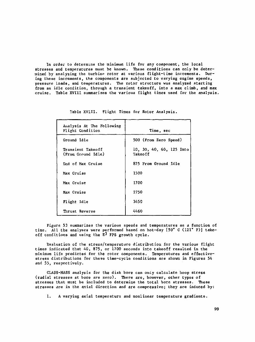
I n order t o determine the minimum l i f e f o r any component, the l o c a l s t r e s s e s and temperatures must be known. These condi t ions can only be de te r - mined by analyzing t h e tu rb ine ro to r a t var ious f l igh t - t ime increments. Dur- ing these increments, t he components a r e subjected t o varying engine speeds, pressure loads , end temperatures . The r o t o r s t r u c t u r e was analyzed s t a r t i n g from an i d l e condi t ion , through a t r a n s i e n t t akeo f f , i n t o a max climb, and max c ru i se . Table XVIII summarizes the var ious f l i g h t times used for the ana lys i s ,
?'able X V I I I . Flight Times for Rotor Analysis.
Figure 53 summarizes t h e varioun speeds and temperatures a s a funct ion of ime. A l l t h e analyses were performed based on hot-day [50° C (121' F]] take- £ £ conditions and using the E~ FPS growth cyc le ,
h a l y s i s A t The Fo L lowing Fl ight Condition
Ground I d l e
Transient Takeoff ( ~ r o m Ground I d l e )
End o f Max Cruise
Max Cruise
Max Cruise
Max Cruise
F l ight I d l e
Thrust Reverse *
Evaluat ian of t h e s t ress / tempera ture d l s t r i bu t io r l f o r the various f l i g h t times ind ica ted t ha t 40, 875, o r 1700 seconds i n t o takeoff r e s u l t e d i n the minimum l i f e predicted f o r the r o t o r components. Temperatures and e f f ec t ive - s t r e s s distributions for these time-cycle condi t ions a r e shown i n Figure8 54 and 55, respec t ive ly .
Time, scc
500 (From Zero speed)
10, 30, 40, 60, 125 In to Takeoff
875 From Ground Idle
15 00
1700
2750
3450
4460
CLASS-MASS ana lys is fo r t h e disk bore can only c a l c u l a t e hoop s t r e s s ( r a d i a l s t r e s s e s a t bore a r e z e r o ) . There are, however, o the r types of s t r e s s e s t h a t must b e included t o determine the t o t a l bore s t r e s s e s , These s t r e s s e s m e i n t h e a x i a l d i r e c t i o n and are compressive; they are induced by:
L . A varying a x i a l temperatura and nonl inear temperature grad ien ts .
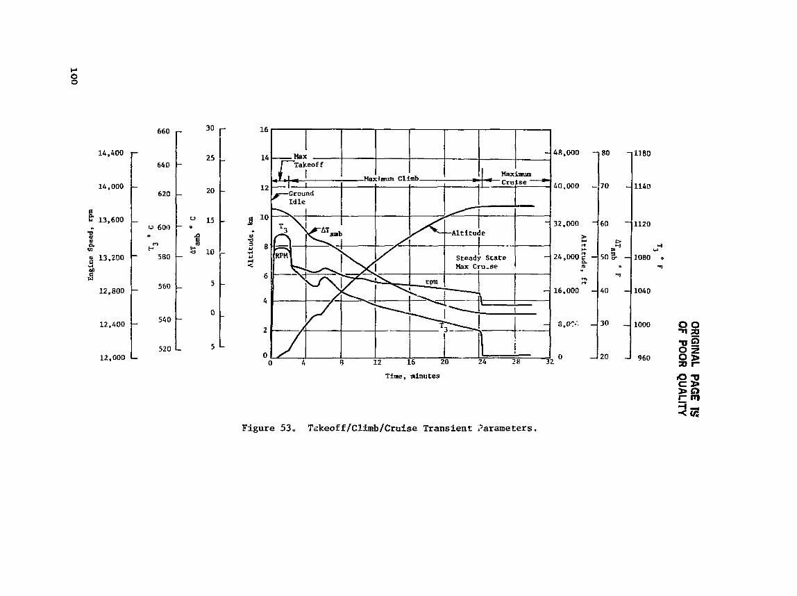
OR
IGIN
AL PAG
E 1S OF
POO
R QU
ALITY
Altitude. ft
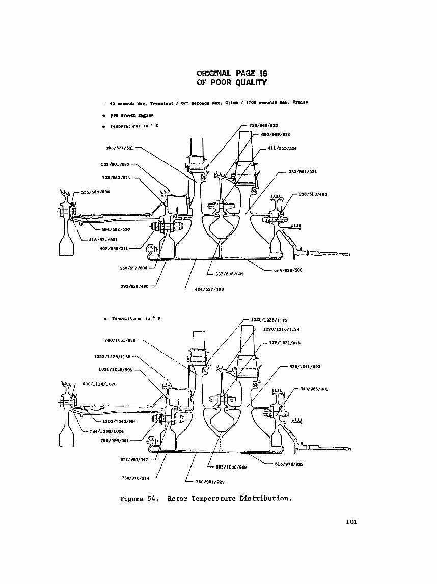
ORlGlNAL PAGE IS OF POOR QUALITY
Figure 54. Rotor Temperature Distribution.
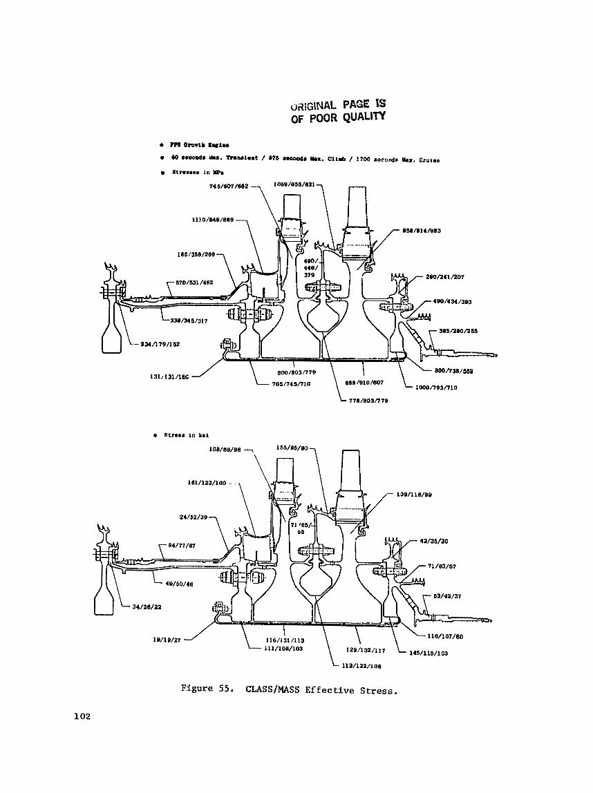
oai~lNAL PAGE TS OF POOR QUALITY
Fi.gure 55. CLASS/MASS Ef fectfve Stress.
2. The bore width t h i c k n e s s r e s u l t i n g i n a compressive s t r e s s a t speed. The t r u e bore s t r e s s d i s t r i b u t i o n can on ly be analyzed by us ing a FINITE computer program.
S t - e s e c o n c e n t r a t i o n s i n the b o l t h o l e s and air-slot: passages were d e t e r - m ~ n e d by u s i n g t h e FINITE computer program o r by t h e a p p r o p r i a t e s t ress-concen- t r a t i o n f a c t o r s from P e t e r s o n . The f in i t e -e lement a n a l y s i s was accomplished by us ing c o n s t a n t - s t r a i n , q u a d r i l a t e r a l e l ements . Due t o symmetry of b o l t - h o l e s , t h e o n t ~ l y s i s and r e s u l t s c a n be accomplished by modeling on ly one-half o f the geometry. Using one-half of t h e symmetrical model r e q u i r e s a n appro- p r i a t e boundary c o n d i t i o n a l o n g the r a d i a l l i n e of symmetry. In a d d i t i o n , t h e t a n g e n t i a l d e f l e c t i o n norm:ll t o the r a d i a l l i n e is r e s t r a i n e d . Boundary con- d i t i o n s (d i sp lacements ) a r e a l s o a p p l i e d a t the i n n e r and o u t e r r a d i i of the model. These d i sp lacements were determined from the CUSS-MASS a n a l y s i s . The CLASS-MASS model f o r s h e l l members i n the v i c i n i t y o f h o l e s was modified t o account f o r a r e d u c t i o n i n bending s t i f f n e s s and f o r s i m u l a t i o n a s an o r t t o - t r o p i c s h e l l . The load of t h e b o l t due t o c e n t r i f u g a l f o r c e s was a p p l i e d a t s p e c i f i c nodes su r round ing t h e h o l e . Thermal g r a d i e n t s were cons ide red by app ly ing t h e a p p r o p r i a t e t empera tu res a t the nodes. The c r i t i c a l f l i g h t t ime t h a t would e s t n b l i s h the LCF l i f e was determined from t h e v a r i o u s CLASS-MASS a n a l y s e s f o r v a r i o u s t i m k s t e p s .
5.1 .4 - Design C r i t e r i a
The HP t u r b i n e was des igned t o meet the o b j e c t i v e life g o a l s d e f i n e d f o r t h e FPS engine. The mechanical a n a l y t i c a l methods and procedures f o l l o w t h e General E l e c t r i c Design P r a c t i c e .
The d e s i g n s for the components a r e based on l i f e p r e d i c t i o n s by us ing m a t e r i a l test d a t e curves . These curves d e f i n e the s t r e s s a t t empera tu re v e r s u s l i f e ( c y c l e s o r hours).
Among t h e more important f a c t o r s a £ f e c t i n g t h e l i f e o f a component are:
S t r e s s r u p t u r e
Creep
Y i e l d
Low Cycle F a t i g u e (LCF)
High Cycle F a t i g u e (HCF)
F r a c t u r e Mechanics.
S t r e s s Rupture - S t r e s s r u p t u r e i n m a t e r i a l s i s a form of f a i l u r e mode which o c c u r s under t h e i n f l u e n c e of time exposure under a s t r e s s and t empera tu re c o n d i t i o n . M a t e r i a l t e s t d a t a i s used t o p r e d i c t r u p t u r e l i f e based on calculated s t r e s s e s and t empera tu res .
Creep - Mater ia l s subjec ted t o s t r e s s e s a t temperature f o r prolonged periods of tune exh ib i t some for^, of deformation. Creep is considered an important c r i t e r i a , e s p e c i a l l y f o r r o t a t i n g s t r u c t u r e s . In the turb ine design, the t o t a l amount of creep i s l imi t ed t o 0 .2%.
Low Cycle Fat igue - S t r u c t u r e s subjec ted t o repeated loads o r thermal s t r e s s e f f e c t s exh ib i t f a t i g u e f a i l u r e , This type of f a i l u r e occurs t t a s t r e s s l eve l lower than a e i n g l e s t r e s s l eve l app l i ca t ion .
The f a i l u r e o r ig ina t e s when a very loca l i zed crack i s i n i t i a t e d i n a material and then propogates u n t i l ma te r i a l separa t ion occurs .
Low cyc le f a t i gue is a f a t i g u e f a i l u r e normally considered t o be l e s s than 105 cycles . The l eve l of s t r e s s a t temperature i e used t o p r e d i c t the LCF based on ma te r i a l t es t d a t a . Thermally induced s t r e s s e s a l s o a f f e c t the p a r t s l i f e .
When geometric d i s c o n t i n u i t i e s e x i s t i n a par t , such a s bol tholee , the s t r e n s concentrat ion e f f e c t s around the ho le s must be considered. Lice pre- d i c t i o n s the re fo re include the s t r e s s concent ra t ion f a c t o r s .
High Cycle Fat igue - High c y c l e f a t i g u e is a s imi l a r mode of f a i l u r e t o an LCF, except t h a t the number of cyc les t o f a i l u r e should exceed lo7 cyc les . HCF f a i l u r e mode i s a funct ion of s t r e s s aZ a temperature l e v e l . S t r e s s concen- t r a t i o n f a c t o r s a l s o have a h igh inftuenci: on ma te r i a l l i f e . Therefore, ca re fu l a t t e n t i o n is always provided t o include a n a l y s i s where s t r e s s concentrat ion fac- t o r s a r e present .
This is e s p e c i a l l y t h e case for blades and blade /d isk dove ta i l s . The vary- ing gas load on the blade ns i t passes through t h e nozzle gas flow i s char- ac t e r i zed by a pulsa t ing pressure . This varying gas pressure induces a vibra- t o r y s t r e s s on every b lade . The b lade v ib ra to ry s t r e s s leve lo whkn combined with the mechanical s t r e s s e s ( c e n t r i f u g a l , gas bending, and thermal) must meet t h e requirements f o r blade l i f e .
F rac tu re Mechanics - Current GE powder metal a l l o y s used i n high-tern- pe ra tu re r z t r s t r u c t u r e s e x h i b i t low cycle f a t i g u e s t r eng th c h a r a c t e r i s t i c s which a r e Zllwer than standard or conventional ma te r i a l forgings. This problem is primar iiy due t o the presence of undetectable surface or subsurface defects . The failure mode c h a r a c t e r i s t i c s can be predicted by f r a c t u r e mechanics methods of ana lys is and must be accounted for i n the life analys is of cu r r en t designs.
S p e c i f i c improvement programs are i n process a t GE t o de f ine improved mate r i a l s processing to minimize the impact of small de fec t s o n f r a c t u r e mechan- ics l i v e s and to improve the c l e a n l i n e s s of t h e powder for f u t u r e engine pa r t design, including E~ HPT follow-on.

DETAILED MECHANICAL DESIGN
5.2.1 Rotor Components: S t r e s s , S t r e s s Concen t ra t ion , LCF LiEe
Figure 55 shows t h e major components o f t h e HPT r o t o r assembly. The s t r e s o c o n c e n t r a t i o n s and LCF l i f e o f t h e t u r b i n e rotor components were d e t e r - mined by employing t h e computer programs, mentioned e a r l i e r , t o e v a l u a t e t h e effects o f l o a d , t empera tu re , and ~ p e e d .
5 . 2 . 1 . 1 Forward HP S h a f t and Outer L iner
The forward p o r t i o n of t h e HP s h a f t , shown i n F i g u r e 57, c o n t a i n s two s e a l t e e t h s l i g h t l y overhung from t h e forward f l a n g e . I n o r d e r t o determine t h e e f f e c t o f t h i s overhang, s p e c i f i c a l l y around t h e f i l l e t , ' a f i n i t e - e l e m e n t a n a l y e i s was made. A maximum s t r e s s of 958 MPa (139 k s i ) occure a t the f o r - ward f a c e of t h e f l a n g e , a t 40 seconds i n t o a c c e l e r a t i o n , r e s u l t i n g i n a mini- mum c a l c u l a t e d LCF l i f e of 11,000 c y c l e s f o r Inco 718,
The maximum concen t ra ted s t r e s s i n the forward s h a f t i s 931 MPa (135 k s i ) a t t h e a f t - f l a n g e b o l t c i r c l e . The p r e d i c t e d 30 LCF l i f e is 14,000 c y c l e s f o r s t a n d a r d Inco 718 a s planned f o r use i n t h e ICLS eng ine .
A m a t e r i a l change t o Supe r Inco 718 i s planned f o r tlre FPS. Super I n c a 718 i s p r e s e n t l y used i n CF6-50 t u r b i n e components; i t improves LCF l i f e by means of b e t t e r g r a i n - s i z e c o n t r o l . The use of Super Inco 718 w i l l a s s u r e an LCF l i f e of 36,000 c y c l e s Eor t h e forward s h a f t .
The m a t e r i a l f o r t h e o u t e r l i n e r i s Ren6 9 5 . The maximum-stress loca - t i o n i s a t t h e c o o l i n g - a i r h o l e s . The maximum s t r e s s i s 951 MPa (138 k s i ) a t 40 seconds i n t o t h e a c c e l , The c a l c u l a t e d LCF l i f e is g r e a t e r than 36,000 c y c l e s .
5 . 2 . 1 . 2 Inducer Disk
The inducer d i s k m a t e r i a l i s AP115. Analys i s of t h e disk d e s i g n l e d t o t h e cho ice of a " race t r ack" shaped b o l t h o l e a s shown i n F i g u r e 58. This shape was chosen for t h e fo l lowing reasons :
a Lower hoop s t r e s s e s w i t h s t r e s s c o n c e n t r a t i o n r e l a t i v e t o a c i r - c u l a r h o l e . Radia l s t r e s s e s with s t r e s s c o n c e n t r a t i o n a r e lower than the hoop s t r e s s e s .
The " race t r ack" h o l e p r e v e n t s bolt: s t u d r o t a t i o n a t assembly. The b o l t s tud h a s a s i m i l a r r ace t r a c k c o l l a r and f i r s w i t h i n t h e inducer disk Iiole. When the assembly torque is induced i n the b o l t , t h e d i s k race Crack provides the r e a c t i o n ; t h u s the b o l t i s n o t al lowed t o t u r n .
The inducer disk s t r e s s e s and p r e d i c ~ e d LCF l ives fo r t h e v a r i o u s c r i t i - c a l l o c a t i o n s are summarized i n F i g u r e 58. A t a11 l o c a t i o n s , the disk meets t h e o b j e c t i v e of 36,000 c y c l e s .


Inducer
OF!C!NAL Pnaz IS OF PC02 QUALITY
HPT Forward S h a f t , Inco 718 (Core Engine and ICLS Tests) or Super Inca 718 (FPS)
Figure 57. Forward Shaft and Outer Liner.
Inducer Disk Seal
Disk AF115
Hole Configuration
Figure 58, Inducer Disk,

5.2.1.3 Impeller And Stage 1 Retention System
After the 76 Stage 1 b lades are assembled from the f ron t of the d i s k , t h e 76 s e a l p l a t e s a r e i nd iv idua l ly ineer ted i n t o each d o v e t a i l s l a t engaging t h e upper tang of the d isk . The s e a l p l a t e func t ions t o minimize purge a i r i n the cavi ty formed between t h e f ron t of the d i s k and Stage 1 inner nozzle support from e n t e r i n g the space between blade shanks, 'Ihe compressor-diecharge a i r used t o purge the c a v i t y and t h e inner flowpath between Blade 1 and Nozzle L is intended t o e x i t i n t o t h e flowpath a t t h i s loca t ion .
I n addi t ion t o coolant-air pumping, t h e impel ler provides a x i a l blade r e t e n t i o n and a Bupport for the b lade wire s e a l . The wire seal is used t o minimize leakage of blade-coolant a i r , thereby increas ing tu rb ine performance.
The " u ~ ' c l i p funct ions to a x i a l l y re ta in the s e a l p l a t e s and a l s o as a windage cover f o r the d i s k post extension. The "U" clip contains one sawcut t o allow fo r assembly. The 360' r e t a i n i n g r i n g is snapp~,d i n pLace a f t e r t h e "U" c l i p has been assembled.
The impeller ma te r i a l i s AF115, Due t o the presence of the r a d i a l vanes along the impel ler web and t h e s e r r a t i o n s i n the hor i zon ta l impeller-support arm, the impel ler ana lys ie requi red a more d e t a i l e d and d i f f e r e n t type of modeling using the CLASS-MASS a n a l y s i s , The impeller model i s shown i n Fig- ure 59. The r a d i a l vanes and s e r r a t i o n s were simulated by s h e l l s (shown shaded) without hoop-carrying c a k a b i l i t y . The proper weight was simulated by changing the d e n s i t y based on an equiva len t s h e l l th ickness . The s h e l l t h i c k - ness simulating t h e vanes was based on an equiva len t s h e l l bending s t i f f n e s s . The r e su l t i ng l o sds from the CLASS-MASS a n a l y s i s were used t o determine the a c t u s l vane s t r e s s .
Maximum s t r e s s e s for the impel le r , determined from the CLASS-MASS ancl- y s i s , occur a t 40 seconds i n t o the takeoff . These s t r e s s e s are shown i n Fig- u r e 6 0 , Strees concent ra t ions occur a t the 38 "race t rack" holes t h a t allow the passage of the expander a i r , used t o cool t h e Stage 1 blades , and a t the i n t e r f a c e between t h e disk web and the impel ler vanes. Nei ther of the a reas a f f e c t the expected 36$000 c y c l e s LCF l i f e of t he impel ler .
5.2.1.4 Stage 1 Disk
The Stage 1 d i s k , shown i n Figure 61, is manufactured from ~ e n 6 95 m a t e r i a l , The disk i s composed of two d i s t i n c t s t ress f load-car ry ing s t ruc- t u r e s , The f i r s t c o n s i s t s of t h e 76 d i s k posts and d o v e t a i l s l o t s a t the o u t e r diameter of the d isk ; these c a r r y the load from the b lades (gag bending and cen t r i fuga l loads) . The second c o n s i s t s of the main body of the d i sk , o r t h e l i v e d isk , and c a r r i e s a l l t h e loads mentioned above and i n t e r n a l forces induced by temperature, a x i a l p ressure , and speed e f f e c t s . In a d d i t i o n , the disk web rabbe t , loca ted i n t h e forward face and above the forward cam, radi- a l l y supportr t h e impel ler .
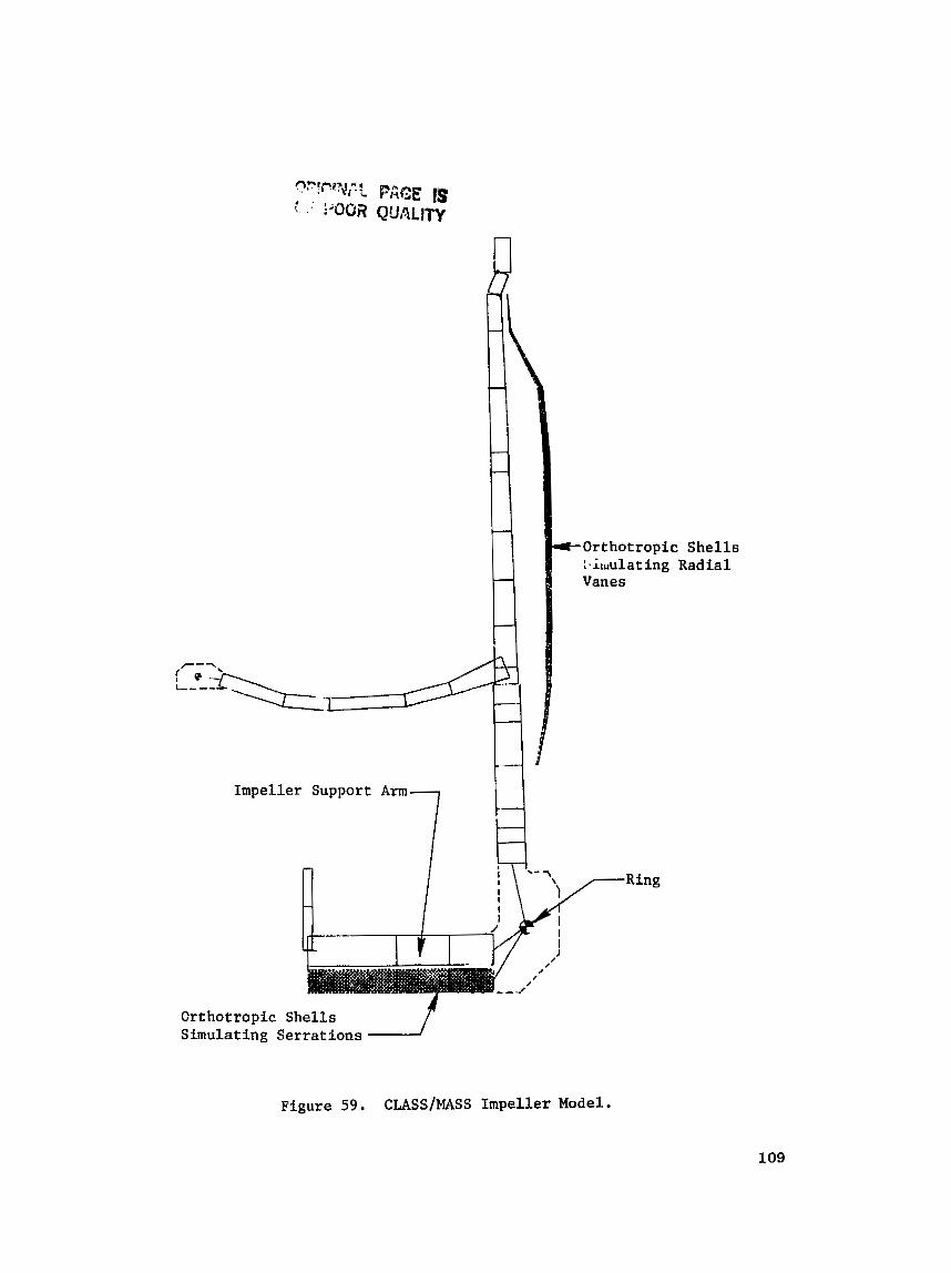
Impeller Support Arm
7 I4 Orthotropic S h e l l s Simulating Serrations f
Figure 59. CLASS/MASS Impeller Model.
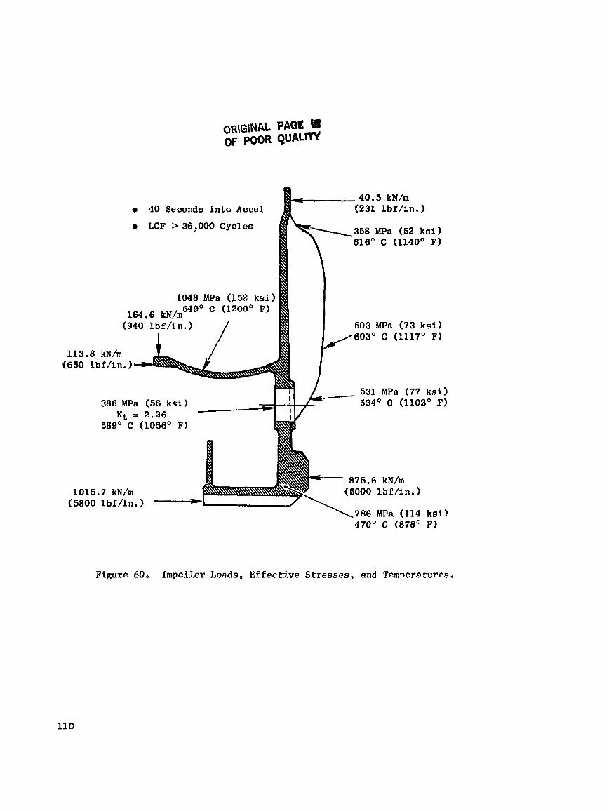
40 Seconds in to Accel 231 kbf/in. 1 LCF > 36,000 Cycles 358 MPa (52 ksi)
616O C (1140° F )
1048 MPa (152 k s i ) 649' C (1200' F)
503 MPa (73 ksi) 603' C (1117' F)
113.8 kN/m (650 lbf / in . )
531 MPa (77 kai) 386 MPa (56 k s i ) 594O C (llOZO F)
1015.7 kN/m (5800 l b f f l n . ) --
786 MPa (114 k s i ) 470' C (878' F)
Figure 60, Impeller Loads, Effective Stresses, and Temperatures.

ORIGINAL PAGE IS OF POOR QUALITY
Material
Figure 61. Stage I Disk Stress Concentration and LCF Life.
Locn t i o n
1 . Farwnrd A r m Air- Passage Slot
2 . Forward Arm F l a n ~ e Air-Pnssnge Slot and Scallop
3. Forwnrd Arm Ring Contai n c r
4 . Forward Arm Scallop
5. Forward Arm A i r Hole
6 . A f t A r m Air-Pnssajie Slot
7 . Forward A r m Bolt Hole
8 . A f t A r m Bolt Hole
9. D i s k Post Notch
Nonl i nn 1 st rcasa
MDa
448
269
ksi
65
39
Time
scc
87 5
4 0
4 0
87 5
875
875
875
87 5
40
K t a LCF Li fc
kilocycles
>lo0
>lo0
>lo0
M 00
36
>I00
Sl OQ
>I 00
>lo0
Temperature
MPo
841
731
1)15
565
1103
469
938
931
827
331 /
OC
541
427
4 58
545
544
553
54 1
552
527
k s l
122
LO6
137
82
160
68
136
135
120
393
455
400
4 2 1
434
276
O F
1006
800
857
1013
1012
1027
1006
1025
980
57
66
58
61
83
4 0
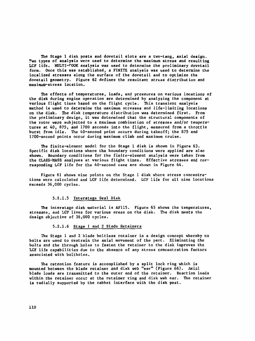
The Stage 1 d i s k poets and d o v e t a i l s l o t s a r e a two-tang, a x i a l design. ?wo types of a n a l y s i s were used t o determine the maximum s t r e s s and r e s u l t i n g LCF l i f e . MULTI-WOK a n a l y s i s was used to determine the prel iminary dove ta i l form. Once t h i e was e s t ab l i shed , a FINITE a n a l y s i s was used t o determine the loca l ized s t r e s s e s along t h e aurface aE t he d o v e t a i l and t o optimize the dove ta i l geometry. Figure 62 de f ines t he r eeu l t an t s t r e s s d i s t r i b u t i o n and maximum-stress l oca t ion ,
The e f f e c t s of temperatures, loads , and pressures on va r ious loca t iono of the disk during engine opera t ion a r e determined by analyzing the component a t var ious f l i g h t times based on the f l i g h t cyc l e . This t r a n s i e n t ana lys ia method i s used t o determine the maximum s t r e s s e s and l i f e - l i m i t i n g loca t ions on t h e d isk . The d i s k temperature d i s t r i b u t i o n wae determined f i r s t . From t h e preliminary debign, it was determined t h a t t h e s t r u c t u r a l components of t h e ro to r were eubjected t o a maximum combination of s t r e s s e s and/or tempera- t u r e s a t 40, 875, and 1700 seconds i n t o the f l i g h t , measured from a t h r o t t l e bu r s t from i d l e , The SO-second point occurs dur ing t akeo f f ; t h e 875 and 1700-second po in t s occur dur ing maximum climb and maximum c r u i s e ,
The finite-element model fo r t h e Stage 1 d i s k is shown i n Figure 63, Speci f ic d i s k loca t ion8 where the boundary condi t ions were appl ied a r e a l s c ahown. Boundary conditj.one for the f ini te-element a n a l y s i s were taken from the CLASS-MASS analyses a t var ious f l i g h t t imes. E f fec t ive s t r e s s e s and cor- responding LCF Life f o r t h e 40-second caee a r e shown i n Figure 64.
Figure 61 shows nine poin ts on the Stage 1 d i s k where s t r e s s concentra- t i o n s were ca l cu la t ed and LCF l i f e determined. LCF l i f e for a l l nine loca t ions exceeds 36,000 cyc l ee .
5.2.1.5 In t e re t age Seal Disk
The i n t e r s t a g e d i s k ma te r i a l i s AFLLS. Figure 65 shows the temperatures, s t r e s s e s , and LCF l i v e s f o r var ious a r eas on the d i s k , The d i s k meets t he design objec t ive of 36,000 cyc le s .
5.2.1.6 Stage 1 and 2 Blade Reta iners
The Stage 1 and 2 blade b o l t l e s s r e t a i n e r i s a design concept whereby no b o l t s a r e used t o r e s t r a i n the a x i a l movement of the p a r t . Eliminating the b o l t s and the through ho le s t o f a s t e n the r e t a i n e r t o the disk improves the LCF l i f e c a p a b i l i t i e s due t o t h e absence of any s t r e s s concent ra t ion f a c t o r s associated with bol tholes .
The r e t e n t i o n f e a t u r e is accomplished by a s p l i t lock r i n g which i s mounted between the blade r e t a i n e r and d i s k web "ear" ( ~ i g u r e 66). Axial blade loads are t ransmi t ted t o the ou te r end of the r e t a i n e r . Reaction loads within the r e t a i n e r occur a t the r e t a i n e r r i n g and d i s k web e a r . The r e t a i n e r i e r a d i a l l y supported by t h e rabbet i n t e r f a c e with t he d i s k post .

ORIGINAL.' FAC2 I.9 OF POOR QUALITY
a Hot-Day Takeoff
30 Seconds into Accel
As-HTP ~ e n e 95
Max. Stress Location 1000 MPa (145 k s i ) 36,000 Cycles
Figure 62, Stage 1 Disk Dovetail ~lastic/~laseic (FINITE) Stress Analysis.

ORIGINAL PAQE IS OF POOR QUALITY
l isk Post Load
Figure 63. Stage 1 Disk Finite-Element Model.
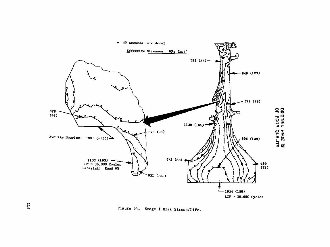
OR
lGlN
Ai FF,EE IS
01: PO
OP Q
UA
LITY
ORlG1NAL PAGE IS OF POOR QUALITY
924 MPa (134 ksi) 708' C (1306' F) >36,000 Cycles
40-sec Acce1
820 MPa (119 ksi) 540' C (1004' F)
869 MPa (126 k s i ) 413' C (775O P) >lo5 Cycles
710 MPa (103 ksi)
814 MPa (118 ksi) 371" C (700° F) 862 MPa (125 ksl) >lo5 Cycles 29Z0 C (557O F)
>lo5 Cycles
Figure 6 5 , Interstage Seal Disk Finlte Zffective Stress Distribution, Temperatur*, and LCF Life.
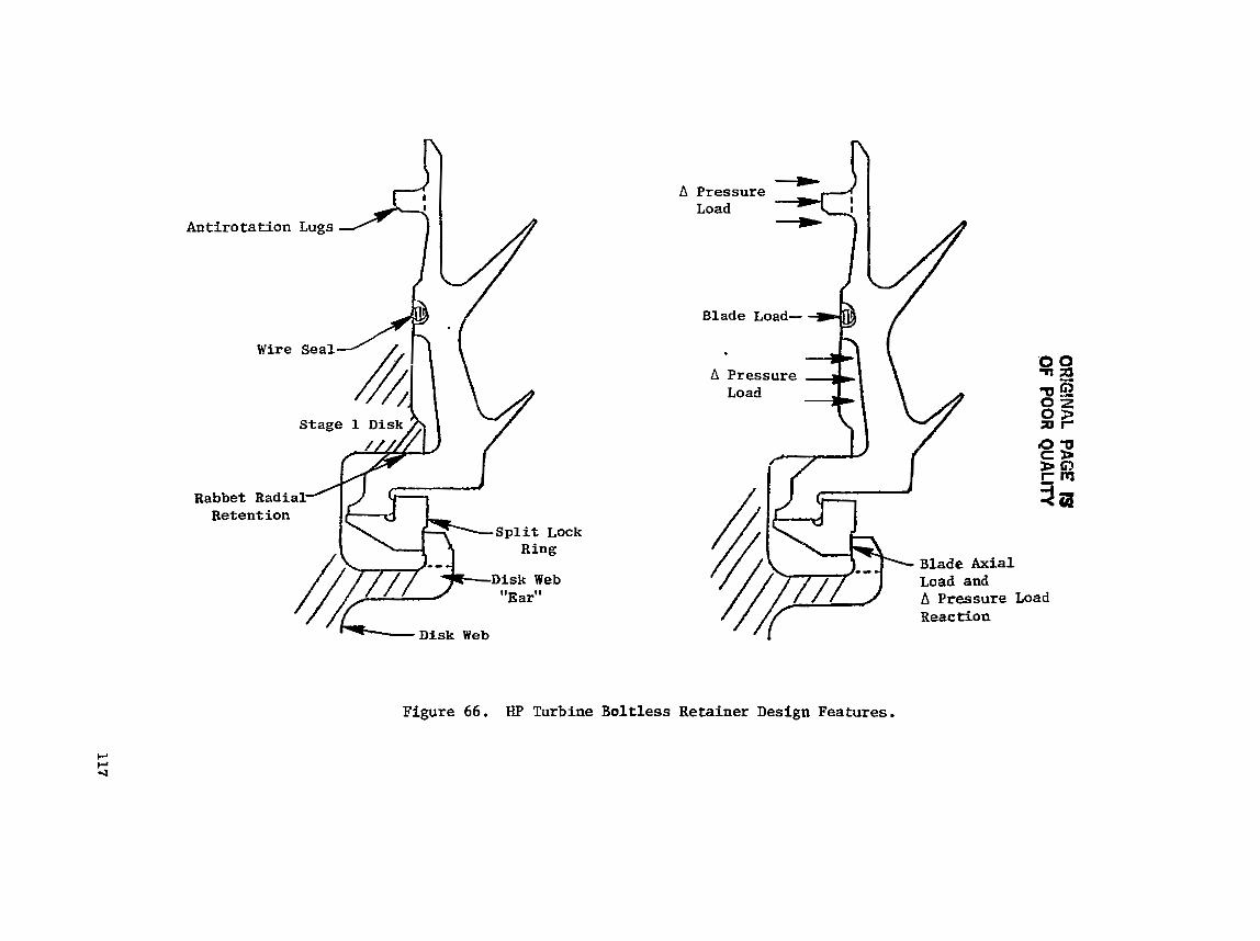
ORIG!MAL
PAGE IS
O
F POO
R Q
UA
LITY

Both r e t a i n e r s were analyzed us ing FINITE elements. The boundary con- d i t i o n s and FINITE model were based on the CLASS/MASS ana lys i s a t the time 40 seconds i n t o the takeoff . The r e s u l t i n g s t r e e a e s and temperatures f a r t h i s condit ion a r e shown i n F igures 67 and 68 f o r t h e Stage 1 and 2 r e t a i n e r s , reepec t i ve ly .
5 . 2 . 1 . 7 Stage 2 Disk
The Stage 2 d iek i s menufactured from Re& 95. The s t r e s s and fat igue- l i f e ana lys is f o r the Stage 2 disk, shown i n Figure 69, is s imi l a r t o the anal- ysis of the Stage 1 diek, The d i s k poet FINITE model and r e s u l t i n g s t r e s s e s o r e shown i n Figure 70. The s t r e s s e a are based on maximum blade loads f o r the ho t-day takeoff condi t ions .
The l i v e d i s k port ion was analyzed ucing the CYANIDE computer program. Location6 on the d i s k where e x t e r n a l loads a r e appl ied (boundary condit ions) were taken from the CLASS-MASS analyois . The combined e f f e c t s of temperature and loads a t t he 40-second case r e su l t ed i n the s t r e e s d i s t r i b u t i o n shown in F igu re 71.
Stress-concentrat ion f a c t o r s were determined f o r 10 d i s k loca t ions . Seven of t h e more c r i t i c a l loca t ions a r e shown i n Figure 69. A review of the f i g u r e i n d i c a t e s t ha t the maximum combined s t r e a s a t near ly a l l l oca t ions occurs 875 second8 a f t e r takeoff ( t h i s t i m e element i~ a t the maximum climb condit ion) . Sca l lops have been added i n the d i s k a f t f l ange t o reduce the e f f e c t i v e s t r e s s concentrat ion (hoop d i r e c t i o n ) , thereby reducing the t o t a l s t r e s s . Calculated -3= LCF l i f e f o r a l l loca t ions i s g r e a t e r than 36,000 cycles.
5 .2 .1 .8 Aft Shaf t /Sea l Disk
The a f t s h a f t was a l s o analyzed using the FINITE computer program with boundary coadi t ions taken from CLASS-MASS. Figure 72 shows the r e s u l t i n g shaft s t r e s s e s for 40 seconds i n t o tlbe hot-day takeoff, The stress o f 807 MPa (116 k s i ) r e s u l t s i n LCF l i f e of 20,000 cycles using fnco 718 mater ia l (3, propclrties), To achieve the l i f e goal requirements f o r the FPS engine, an improved Inco 718 (super Inco 718) would be required. The present Inco 718 mater ial LCF l i f e i s l imi t ed t o 20,000 cyc le s . Using Super Inco 718 f o r t h e f l i g h t propulsion system, the LCF l i f e w i l l exceed the ob jec t ive of g rea t e r than 36,000 LCF cyc les , For the ICLS and core engine, the ma te r i a l re leased t o manufacturicg i s standard Inco 718.
5.2.1.9 Stage I Blade
The Stage 1 blade i s a n air-cooled design using c a s t , DS R e d 150 m a t e r i a l . The major f ea tu re s and cool ing c i r c u i t s a r e shown i n Figure 73. The blade rupture- l i fe p red ic t ions a r e baaed on the 2-hour design mission showc i n Table X I X .
In order t o conduct a r e a l i s t i c mission-qix ana lys i s , cycle data were u t i l i z e d for var ious ambient cond i t i ons . Cycle d a t a used were speed, cool- a n t and gas temperatures, and gas loada. Analy t ica l i nves t iga t ion t o de te r - mine the blade rupture l i f e i nd ica t ed that three f l i g h t po in ts i n the mission,


513O C (955' F)
472O C (881' F)
1034 kPa (150 ksi) 455' C (851° F) 3 6 0 0 0 Cycles 758 kPa (110 ksi)
463O C (866O F) 3 6 0 0 0 Cycles
896 kPa (130 ksi) 447' C (837' F) >36000 Cycles
40-second Into Acceleration Temperature Distribution
Figure 68. Stage 2 A f t Blade Retainer Temperature and Stress Profile.
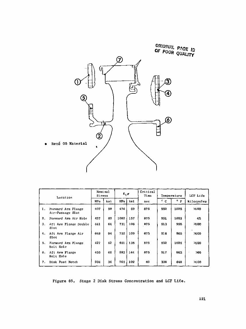
Figure 69. Stage 2 Disk Stress Concentration and LCF L i f e .
Locnt i o n
1 . Forward A r m Flange Air-Passage Slot
2. Forward A r m Air Ilolc
3 . A r t A r m Flange Double Slot
4. Aft A r m Flange Air Slot
5 . Forward A r m Flange Bolt Hole
6 . A f t Arm Flange Bolt Hole
7 . D i s k Post Notch
Nomi nal Stress
MPa
407
427
441
648
427
455
234
Ktu
ksi
59
62
64
94
62
66
34
Crit ical Time
sec
875
875
87 5
875
875
875
4 0
h1Pn
176
1082
73L
ksi
69
157
106
LCF L i f e
k i locyc les
>I 00
4 5
>lo0
Y O 0
YO0
Xi0
>lo0
Temperature
752 1 109
C
552
551
51 3
51 8
552
51 7
338
931
993
703
O F
1025
1023
955
965
1025
963
640
135
144
102

ORIGINAL Ph", ''" OE POOR QUALl'r'i
L i n e e of Constant Stress
a FPS Growth Engine, Hot-Day Takeoff
30 Seconds into Accel
As-HIP PM ~ e n L 95
1007 MPa (146 ksi) 36,000 Cycles 654' C (1210° F)
938 MPa (136 ksi) 36,000 Cycles 64g0 C (1200° F)
Figure 70. Stage 2 Disk Dovetail Elastic/~lastic (FINITE) Stress Analysis.
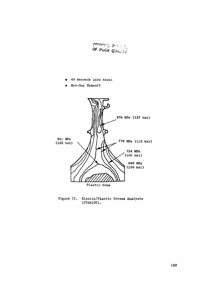
a 40 Seconds into Acce l
Hot-Day Takeoff
MPa
876 MPa (127 k s i )
779 MPa (113 k s i )
P l a s t i c Zone
Figure 71. Elastic/Plastic Stress Analysis (CYANIDE).
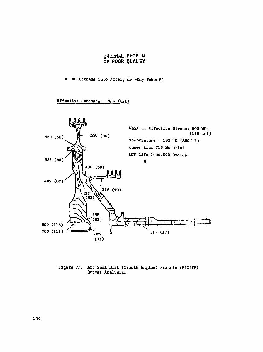
QRIG~IJAL PAGE BS OF POOR QUALIW
40 Seconds i n t o Accel, Hot-Day Takeoff
Effective Stresses: Wa ( k s i )
Maximum Effective Stress: 800 MPa (116 ksi)
Temperature: 193' C (380' F)
Super Inco 718 Material
LCF L i f e > 36,000 Cycles
f
Ffgure 72. A f t Seal Disk (Growth Engine) Elastic (FINiTE) Stress Analysis.
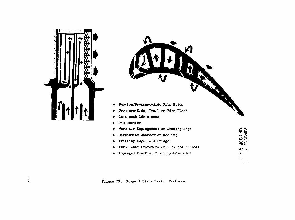
Suction/Pressure-Side Film Holes
Pressure-Side, Trailing-Edge Bleed
Cast Re& 150 Blades
PVD Coating
Warm A i r Impingement on Leading Edge
Serpent ine Convection Cooling
Railing-Edge Cold Bridge
Turbulence Promoters on Ribs and A i r f o i l
Impi nged-Pin-Fi n , Traili ng-Edge Slo t
Figure 73. Stage I Blade Design Features.
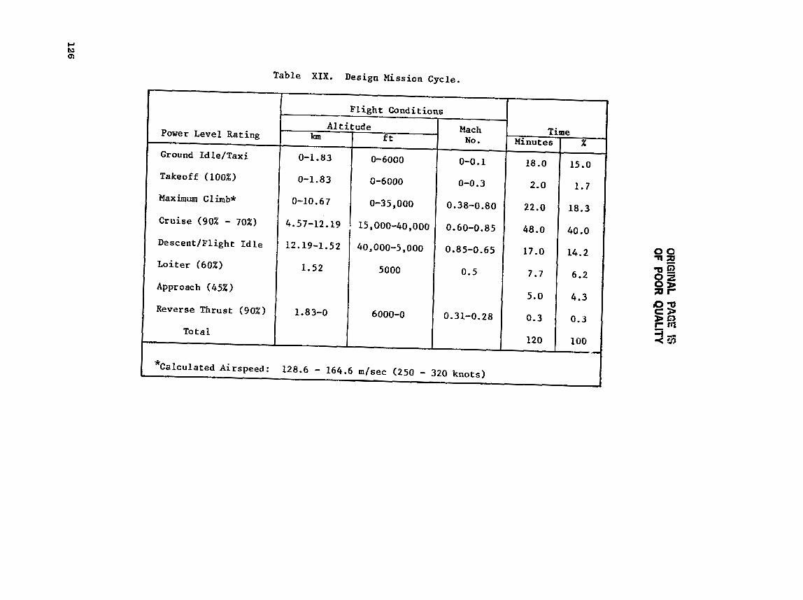
ORIG
INAL PAGE ES
OF PO
OR
QU
ALIW
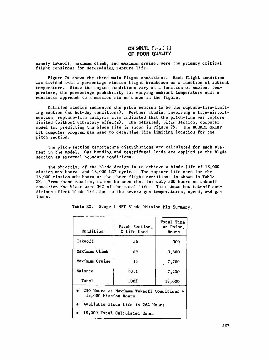
ORIG!Nfi,L RisL? 5'5 OF POOR Q'JALIW
namely t akeo f f , maximum climb, and maximum c r u i s e , were the primary c r i t i c a l f l i g h t conditons for det t rmining rupture l i f e .
Figure 74 shows the t h ree main f l i g h t condi t ions . Each f l i g h t condi t ion &.as divided i n t o a percentage rnission f l i g h t breakdown na a func t ion of ambient temperature, Since the engine condi t ions vary a s a funct ion of ambient tern- perature, t he percentage p robab i l i t y f o r varying ambient temperature adda a r e a l i s t i c approach t o a mission mix as shown i n the f igure .
Derailed s tud ie s ind ica ted the p i t c h sec t ion t o be the rupture-life-lirnit- ing sec t ion ( a t hot-day condi t ions) . Further studiefi involving a f ive-air fo i l - s ec t ion , rup tu re - l i f e ana lys i s a l s o ind ica ted t h a t thz p i tch- l ine was rupture l imi ted (without v ib ra to ry e f f e c t s ) . The d e t a i l e d , p i tcn-sec t ion , computer model fo r p red ic t ing t h e blade l i f e is shown in Figure 75. The BUCKET CREEP 111 computer program was used t o determine Li fe- l imi t ing loca t ion f o r t h e p i t c h sec t ion .
The pi tch-sect ion temperature d i s t r i b u t i o n s a r e ca lcu la ted f o r each ele- ment i n the model. G a s bending and c e n t r i f u g a l loads are a p p l i e d t o the blade sec t ion as ex te rna l boundary condi t ions .
The ob jec t ive of t h e blade des ign is t o achieve a Glade l i f e of 18,000 miss ion mix hours and 18,000 LCF cyc les . The rupture l i f e used for t he 18,000 mission mix hours a t t h e three f l i g h t condi t ions is shown in Table XX. From these r e s u l t s , i t can b e seen t h a t f o r only 300 hours a t takeoff condition the blade uses 36% of the t o t a l l i f e , This shows how takeoff con- d i t i o n s a f f e c t blade l i f s due to t h e severe gas temperatures, speed, and gas loads.
Table XX, Stage 1 HPT Blade Mission Mix Summary.
Condition
Takeoff
Maximum C 1 imb
Maximum Cruise
Balance
Total
250 Hours a t Maximum Takeoff Conditions = 18,000 Mission Hours
Available Blade Li fe is 264 Hours
18,000 Total CaLculated Hours
P i t ch Sec t ion , % Li fe Used
3 6
49
15
(0.1
100%
Tota l Time a t Point,
Hours
300 I
3,300
7,200
7,200
18,000

OR
IGIN
AL PAG
E IS
OF: POOR QU
ALITY

Figure 75. Stage I Blade, BUCKET-CREEP Program Model (P i tch Section).

The combined mechanical and thermal e f f e c t s over 18,000 mission hours a r e equivalent to 250 hours a t the severe maximum hot-day takeoff condi t ions . The blade\ rupt- re l i f e meets t h i s requirement.
A f ive-sec t ion a i r f o i l model, ehown i n Figure 76, was generated t o de te r - mine the change i n blade t i l t . During the 18,000 hours of blade l i f e , t h i s change can be induced by the c reep and p l a s t i c i t y e f f e c t s caused by the mechan- i c a l and thermal Loads. Since blade t i l t is incorporated i n elre blade c a s t i n g to counteract t h e gas moment, any s i g n i f i c a n t v a r i a t i o n i n t i l t w i l l r e s u l t i n changing the des i red mechanically induced a i r f o i l s t r e s s e s . The change i n blade t i l t e f f e c t e due t o c reep was found t o be i n s i g n i f i c a n t , Generating the f ive-sect ion a i r f o i l model a l s o allowed eva lua t ion of t he rupture l i v e s a t var ious blade spans.
The r u p t ~ r r c - l i f e hours, when combined with the r e l a t i v e v ib ra to ry - s t r e s s l eve l e between sec t ions , a r e used t o p red ic t minimum l i f e a t the c r i t i c a l a i r - f o i l loca t ion and span sec t ion . The combined e f f e c t s of mechanical e t r ee ses ( thermal , gas bending, and c e n t r i f u g a l ) and v ib ra tory s t r e s s e s i nd ica t e t ha t t he t r a i l i n g edge a t 25% span is the l i f e - l i m i t i n g blade Location. This l i f e ana lys i s is based o : ~ f i r s t - f l e x v ib ra to ry mode. The allowable v ib ra to ry s t r e s s of 145 MPa ( 2 1 k s i ) , s i n g l e amplitude, for the f i r s t - f l e x mode i s more than adequate t o meet the 18,000 hours blade l i f e , Vibratory l e v e l s a r e expected to be well below these values.
The blade a i r f o i l LCF l i f e pred ic t ion i s based on determining t h e t o t a l l o c a l s t r a i n experienced dur ing t r ans i en t a c c e l and decel . L i fe p red ic t ion i s determined by using t h e mater ia l - s t rength LCF data curve ( a t temperature) f o r the same blade s t r a i n l e v e l s .
The engine t r ans i en t a n a l y s i s cons is ted of determining the turb ine blade environment due t o engine speed and temperature from s t a r t t o ground i d l e , acce l e ra t ing t o maximum takeoff f o r 2 minutes, and then dece l e ra t ing t o ground id l e . These basic excursions and engine measured parameters a r e shown i n Figure 77 . The blade a i r f o i l temperatures are defined using the ecgine parameters. The BUCKET CREEP 111 program was used t a analyze the thermal and mechanical s t r a i n s during the t r a n s i e n t , The blade ex te rna l condi t ions consis ted of varying c e n t r i f u g a l load and gas bending moments as a funct ion of f l i g h t condi t ion .
The r e s u l t i n g s t r e s s c h a r a c t e r i s t i c f o r the leading-edge fiLn hole ( p i t c h sec t ion ) vereus time is shown i n Figure 78. The leading-edge loca t ion was determined to r e s u l t in the minimum LGF l i f e . S t a r t i n g from zero speed (zero s t r e s e ) , the leading edge is seen t o s l i g h t l y go i n t o e t e n s i l e s t r e s s . This i s the r e s u l t o f acce l e ra t ing the engine using the engine s t a r t e r . Fuel i s introduced a t around 22 seconds and i s i gn i t ed . The e f f e c t i s a f a s t e r tem- pera ture r i s e of the leading edge r e l a t i v e t o the average f o r the whole a i r - f o i l sect ion. The thermal s t r e s s e s are compressive and h igher than the ten- s i l e - s t r e s s e f f e c t s of c e n t r i f u g a l , thereby d r i v i n g the leading edge i n t o a n e t compressive s t r e s s . A s the d i f fe rence between the bulk temperature of the sec t ion and t h e l o c a l temperature of the leading edge diminishes, t he compres- s i v e thermal s t r e s s e s diminish, thereby reducing the net compressive s t r e s s e s (22 t o 300 s e c ) . The time between 22 and 300 seconds is considered combustor
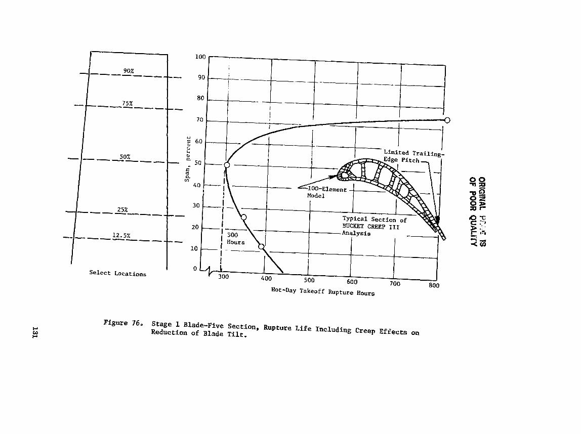
ORlG
iNAL P
r.i.4 19 OF
POO
R QU
ALC
rY

OR
~O~N
AL PA
GE la
OF. POOR QU
ALITY
Tem
peratu
re, 8
0
P, 0
r4 rl
I
8 I I
Temperature, C

ORlGlNAU IS
.OE POOR QU
AL
~W
Lnngitudinal
Stress, ksi
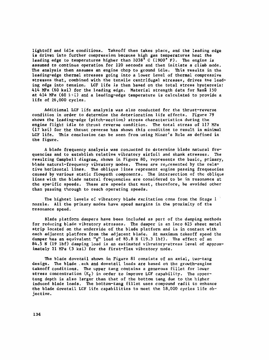
l i g h t o f f and i d l e condit ions. Takeoff then takes p l ace , and the leading edge i e driven i n t o f u r t h e r compression because high gas temperatures heat the Leading edge t o temperatures higher than 1038' C (1900' F ) . The engine i s assumed t o cont inue operat ion f o r 120 seconde and then i n i t i a t e a climb mode. The ana lys is then assumes an engine chop t o ground i d l e . This r e s u l t s i n the leading-edge thermal s t r e s s e s going i n t o a lower l e v e l of thermal compressive s t r e s s e s t h a t , combined with the t e n s i l e c e n t r i f u g a l s t r e s s e s , d r ives the lead- ing edge i n t o tension. LCF l i f e i s then based on the t o t a l s t r e s s hys t e re s i s : 414 MPa (60 ksi) f o r the leading edge. Mater ia l s t r eng th da t a f o r ~ e n E 150 a t 414 MPa (60 b r i ) and a leading-edge temperature i s ca lcu la ted t o provide a l i f e of 26,000 cyc le s .
Additional LCF l i f e ana lys i e was a l s o conducted f o r the thrust-reverse condit ion in o rde r t o determine the d e t e r i o r a t i o n l i f e effects. Figure 79 shows t h e leading-edge (p i tch-sec t ion) s t r e s s c h a r a c t e r i s t i c s during the engine f l i g h t i d l e t o t h rus t reverse condi t ion . The t o t a l s t r e s s of 117 MPa (17 ksi) f o r the t h r u s t reverse has shown t h i s condi t ion t o r e s u l t i n minimal LCF l i f e . This conclusion can be seen from using Miner's Rule a s defined i n t he f igure.
A blade frequency ana lya i s was c o n ~ u c t e d t o determine blade na tu ra l Ere- quencies and t o e s t a b l i s h r e l a t i v e v ib ra to ry a i r f o i l and shank s t r e s s e s . The r e s u l t i n g Campbell diagram, shown i n Figure 80, represents the basic, primary, blade natural-frequency v ib ra to ry modes. These a r e repcesented by the rela- t i v e hor izonta l l i n e s . The obl ique l i n e s r ep re sen t engine passing frequencies caused by var ious s t a t i c flowpath components. The i n t e r s e c t i o n of the oblique l i n e s with the blade na tu ra l f requencies a r e considered t o be in resonance a t t he s p e r i f i c speeds. These a r e speeds t ha t must, t he re fo re , be avoided other than passing through t o reach ope ra t ing speeds.
The h ighes t l e v e l s o: v ib ra to ry blade e x c i t a t i o n come from the Stage 1 nozzle . A l l t he prirr-ary modes have speed msrginn i n the proximity of the resonance speed.
Blade platform dampers have been included a s pa r t of the damping methods for reducing blade v ibra tory s t r e s s e s . The damper is an I n c o 625 sheet metal s t r i p located on the underside of t he blade platform and i s i n contac t with each adjacent platform from the ad jacent blade. A t maximum takeoff speed the damper has an equiva len t "g" load of 85.8 N (19.3 l b f ) . Th2 e f f e c t of an 84.5 N (19 l b f ) damping load is an estimated v ib ra to ry - s t r e s s l eve l of approx- imately 21 MPa ( 3 ksi) fo r the f i r s t - f l e x v ib ra to ry mode.
The blade d o v e t a i l shown i n Figure 81 c o n s i s t s of an a x i a l , two-tang design. The blade .eck and dovetail Loads are based on the growth-engine takeoff condi t ions. The upper tang conta ins a generous f i l l e t f o r lower s t r e s s concentrat ion in order t o improve LCF c a p a b i l i t y . The upper- t ang depth i s a l s o l a rge r than t h a t of the bottom tang due t o the higher induced blade loads . The bottom-tang f i l l e t uses compound r a d i i t o enhance the blade d o v e t a i l LCF l i f e c a p a b i l i t i e s t o meet the 18,000 cycles l i f e ob- j ec t ive .
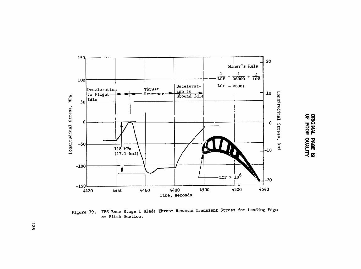
OR
IGIN
AL PAG
E IS
OF POO
R QU
ALITY
Longitudinal Stress, ksi
0
0
d
0
0
@4
f-i rl
N
I I
0
0
0
0
0
0
C
In
0
m
m
0
u
d
rl
I rl
7
I I
~m
's
sa
~?
~
-pu
~p
n~
xS
uo
y
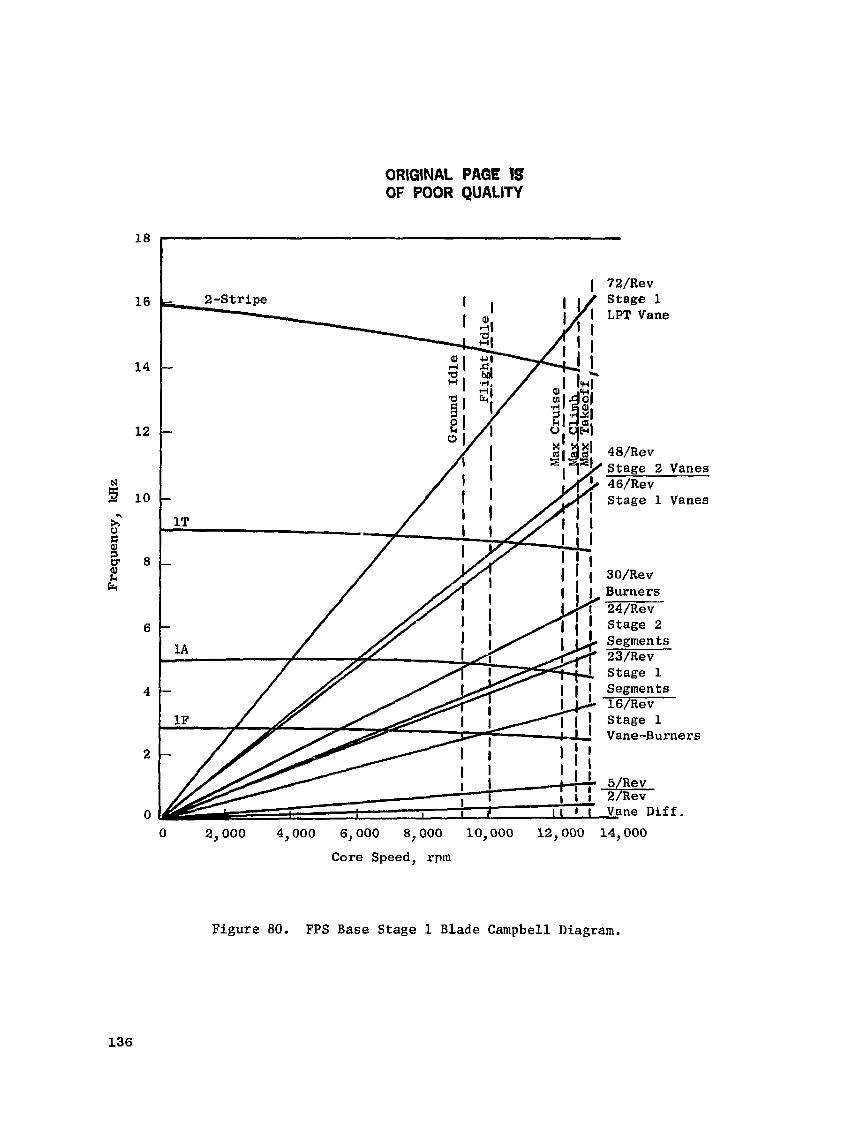
ORIGINAL PAGE IS OF BOOR QUALITY
0 2,000 4,000 6,000 8,000 10,000 12,000 14,000
Core Speed, rpm
Figure 80. FPS Base Stage 1 Blade Campbell Diagram.

CRiGINAL PAGE IS OF POOR QUALITY
a Low Cycle Fatigue L i f e Exceeds 18,000 cycles
Combined Stress with Kt Neck Width
0.952 cm (0.375 in,)
9.820 cm (0.323 in.)
a Ho t-.Day Takeoff Conditions
e N = 13,948 rpm
a Reng 150, 30 Properties
Axial Chord = 3.45 cm (1.36 in.)
Figure 81. Stage 1 B lade Dovetail Stress.

The blade dove ta i l f o r S tages h and 2 was analyzed using the MULTI HOOK computer program. The input t o t h e use of t h i s program includes the c e n t r i - fuga l Loade and n e t biade moments (Mx and Mg) e x i e t i n g a t the g lade dove ta i l mesh. These loads a re used as t h e ex t e rna l boundary condit ions i n using the MULTI HOOK program. The program converts these loads i n t o an equivalent load a t the four corners of each tang and a l s o a t the center of the a x i a l length. S t r e s s e s a r e a l e 0 defined along the dove ta i l mesh radius a t 15 ' in te rva ls .
GE experience has shown t h a t the ca lcu la ted maximum s t r e s s l e v e l s using t h i e program a r e higher r e l a t i v e t o s t r e s s e s obtained using FINITE. F ie ld ex- per ience has a l s o shown d o v e t a i l Lives t o be higher r e l a t i v e t o ca lcu la ted , va lues , The l a t e s t t e s t experience has been the CF6-50 Stage 1 blade, Rene 150 mater ia l , which was run f o r 1000 "c" c y c l e s , No cracks have been observed i n these blades. Addit ional ly t h e E~ blade ca lcu la ted s t r e s s level . a r e lower than t h e CF6-50 (Rene 150 ma te r i e l ) Stage 1 blade, while the Stage 2 b lade s t r e s s e s are very s imi l a r (three-tang des ign) .
Although the re i s an a x i a l compressive s t r e s s induced i n the d o v e t a i l , i t i s f e l t t ha t t h i s i s more than o f f s e t by the h igher ca lcu la ted s t r e s s values obtained by us ing MULTI HOOK computer program r e l a t i v e to a 3-D f i n i t e ana lys i s .
The preeence of the cool ing hole may have some e f f e c t on t h e t angen t i a l vec to r load. Since these Loads can b e t ransmi t ted on ly across the r i b s , a nonuniform d i s t r i b u t i o n may a l s o e x i s t . Also the Kt e f f e c t s may be s l i g h t l y d i f f e r e n t ,
I n order t o assess the l e v e l of s t r e s s d i s t r i b u t i o n , a 3-D model of t h e d o v e t a i l is be ing made, The effects of the cool ing hole s l o t s , however, s h a l l be t rea ted a s a 2-D.
5.2.1.10 Stage 2 Blade
The Stage 2 blade i s an air-cooled design using c a s t , DS ken; 150 mater ia l . The design f ea tu re s and cool ing geometry are shown i n Figure 52. The blade rup tu re - l i f e p red ic t ions are based on the 2-hour mission a s def ined for t he Stage 1 blade.
The procedure defined t o p r e d i c t the rupture l i f e was based on using t h e cycle d a t a information of speed, coolant and gas temperatures, and gas l oads . Detai led rupture a n a l y s i s a l s o ind ica ted t h a t the rupture l i f e was influenced by t h r e e f l i g h t p o i n t s i n the mission: t akeo f f , maximum climb, and maximum c r u i s e .
A mission-mix, rup tu re - l i f e ana lys i s s i m i l a r t o t h a t described for t he Stage 1 blade r e su l t ed i n Table X X I ,
A d e t a i l e d blade p i tch-sec t ion computer model for p red ic t ing t h e b lade l i f e was generated a s shown i n F igure 53. The BUCKET CREEP 111 computer pro- gram was used t o determine t h e l i m i t i n g l i f e l oca t ion f o r t h e p i t ch sec t ion .

Cast Ren6 150 B l a d e s
PVD Coating
Serpent ine Convection Coo l ing
No Film-Cooling or Trailing-Edge Holes
T i p , Pressure-Side Coolant E j e c t i o n for Coo l ing E x i t and Increasing Torque
Turbulence Promoters on Ribs and A i r f o i l Wal ls
Figure 82. Stage 2 Blade Design Features.

ORIGINAL PAGE IS OF POOR QUALITY
The temperature d i s t r i b u t i o n s were ca l cu la t ed fo r each element i n the model. The mechanical loads , c e n t r i f u g a l and gas bending, are appl ied a s e x t e r n a l boundary condit ions.
Table X X I . Stage 2 HPT Blade Mission Mix Summary.
The combined mechanical and thermal s t r e s s e s r e s u l t i n the rupture l i v e s shown in Figure 84. As ind ica ted i n t he f i g u r e , t he b lade l i f e ob jec t ive of 18,000 hours is achievable.
Condition
Takeoff
Maximum C 1 imb
Maximum Cruise
Ba 1 anc e
Total
Blade LCF l i f e -p red ic t ion ana lye i s f o r t he p i t c h s ec t ion was based on determining the t o t a l s t r a i n occurr ing i n the l o c a l sur face of t h e a i r f o i l . The ana lys i s considered t r a n s i e n t condi t ions from the i n i t i a l combustor l i g h t o f f , Lhraugh ground i d l e , i n t o t he t akeo f f , and back t o ground i d l e . The ana lys is considered t h e combined e f f e c t s of s t r e s s and temperature and indica ted the t r a i l i n g edge t o be the limiting LCF loca t ion . Calculated LCF l i f e is g r e a t e r than 30,000 cyc les .
A blade v ib ra to ry a n a l y s i s was conducted t o determine the natural. fre- quencies, Figure 85 r ep resen t s the Stage 2 blade Campbell diagram f o r t h e primary frequency modes.
340 Hours a t Maximum Takenff = 18,000 Mission Hour e
Available Blade Life i s 341 Hours
18,000 Tota l Calculated Hours
Pi t ch Sec t ion , 4 L i f e Ueed
33 ,S
48.2
18.3
(0.1
i00
The f i r s t - t o r s i o n a l , blade-frequency mode i s i n proximity t o t h a t of t h e 24/rev Stage 2 vane segments a t t he f l i g h t i d l e condi t ions . Due t o the low speed and pressures , t h e l e v e l of e x c i t a t i o n is considered t o be low. Once the blade frequencies are determined from a c t u a l bench t e s t i n g , a more d e t a i l e d Campbell diagram can be e s t ab l i shed which w i l L more accu ra t e ly pre- d i c t the resonance loca t i ons ,
Toral Time a t Po in t , Hours
300
3,300
7,200
7,200
18,000
OHiGINAL PAGE IS OF POOR QUALITY
Figure 8 3 . Stage 2 Blade BUCKET-CREEP Program Model.
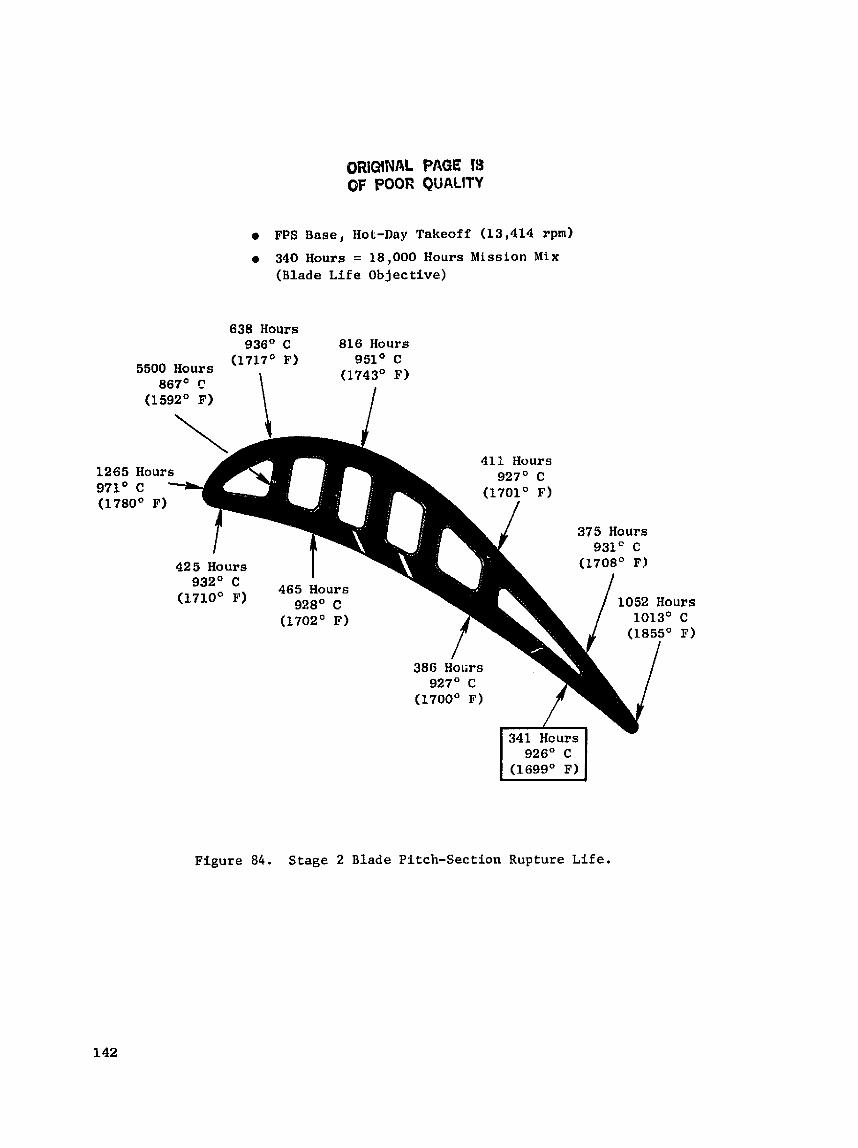
ORIGINAL PAGE IS OF POOR QUALITY
FPS Base, Hot-Day Takeoff (13,414 rpm)
340 Hours = 18,000 Hours Mission Mix ( B l a d e Life Objective)
638 Hours 936') C 816 Hours
(1717' F) 951' C 5500 Hours
867' C \ (1743O F)
4 1 H ~ o r s
375 Hours
Figure 8 4 . Stage 2 Blade Pitch-Section Rupture Life.

Oii:L;;s,r:rt.. ~"i4Cid fQ! OF POOR QUALITY
0 2,000 4,000 6,000 8,000 10,000 12,000 14)000
Core Speed, rpm
Figure 85. FPS Base Stage 2 Blade Campbell Diagram.
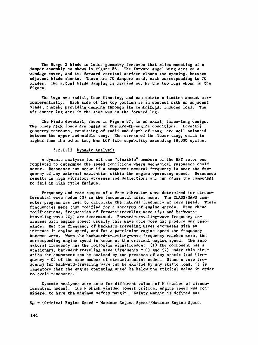
The Stage 2 blade includca geometry f e e ~ u r e s t h a t a l low mounting of a damper assembly a s shown in Figure 86. The forward angel wing a c t s ss a windage cover, and i ts Eorward v e r t i c a l eurfece c loses the openings between ad jacent blade shanke. There arc ?O dampera used, each correeponding t o 70 b lades . Thc a c t u a l blade damping i s c a r r i e d out by t he two Lugs shown i n the f igu re .
The lugs are r a d i a l , free f l o a t i n g , and can r o t a t e a l imi ted amount c i r - c i lmferent ial ly . Each s ide of the top por t ion i s i n con tac t with an ad jacent b lade , thereby providing damping through i t e cen t r i fuga l induced load. The a f t damper lug a c t s i n the aame way a s Lhe Eorward lug.
The blade dove ta i l , shown i n Figure 87, is an a x i a l , three-tang design. The blade neck loads are based on the growth-engine condit ione. Dovetaii geometry contours , cons i s t i ng of r a d i i and depth of tang , a r e we l l balanced between the upper and middle tang. The s t r e s s of the lower tang, which is higher than the o ther two, has LCF Life c a p a b i l i t y exceeding 18,000 cyc les .
5.2.1.11 Dynamic Analysis
A dynamic ana lys i s f o r a l l t h e " f lex ib le" members of the HPT r o t o r was completed t o determine t h e speed condit ions where mechanical resonance could occur , Reaonance can occur i f a component na tu ra l frequency i s near the f re - quency of any ex te rna l e x c i t a t i o n within the engine opera t ing speed. Resonance results i n high v ibra tory s t r e a s e s and d e f l e c t ions and can cause the component to f a i l i n h igh cyc le f a t i gue ,
Frequency and mode shapes of a f r e e v ib ra t ion were determined l o r circum- f e r e n t i a l wave nades (N) i n the fundamental a x i a l mode. The CLASS/MASS com- pu te r program was used t o c a l c u l a t e the na tu ra l frequency a t zero speed. These frequencies were than modified f o r a spectrum of engine speeds. From t h e a e modif icat ions, f requencies of forward-traveling wave ( f F ) and backward- t ravel i r rg wave ( fg ) a r e determined. Forward-traveling-wave frequency in- c r e a s e s wi th engine speed; u sua l ly t h i s wave mode does not produce any reso- nance. But t he frequency of backward-traveling waves decreases with an inc-ease i n engine speed, and f o r a p a r t i c u l a r engine speed the freqlreacy becomes zero. When the backward-traveling-wave frequency reaches zero , the corresponding engine speed i s known as t he c r i t i c a l engine speed. The zero n a t u r a l frequency has the fol lowing s ign i f i cance : (1) the component has a s t a t i ona ry , backward-traveling wave (frequency = 0) and ( 2 ) under t h i s s i t u - a t i o n the coruponent can be exc i t ed by the presence of any s t a t i c Icsd (£re- quency % 0 ) of the same number of c i rcumferent ia l nodes. Since a zero £re- quency for backward-traveling wave can be exc i tzd by any s t a t i c load, i t i e mandatory t h a t t h e engine ope ra t ing speed be below t h e c r i t i c a l value in order to avoid resonance.
Dynamic analysec were done f o r d i f f e r e n t values of N (number of circum- f e r e n t i a l nodes). Tile N which yielded lowest c r i t i c a l engine speed was con- sidered to have t h e minimum safety margin, Safety margin i s defined a s :
SM = ( C r i t i c a l Engine Speed - Maximum Engine Speed)/~aximum Engine Speed.
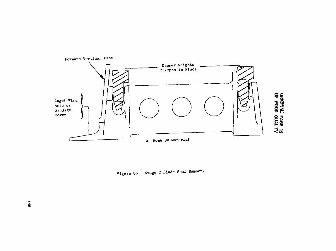
tJF?!GlNRC PAGE is
OF PO
OR Q
UA
LlW

ORIGNAL PAGE IS OF POOR QUALITY
a Low Cycle Fatigue L i f e Exceeds 18,000 Cycler
(30,520 lbf) /
- (117.1 ksi)
Blade A Combined Streas
Neck Width
0.988 cm (0.389 in.)
0,866 cm (0 .341 in.)
Hot-Day Takeoff Conditions
N - 13,948 rpm
o Ren$ 150, 30 Properties
a Axial Chord = 4.83 cm (1.9 in.)
Figure 87. Stage 2 Blade Dovetail Stresses.

ORIGINAL PAGE IS OF POOR QUALIN
Table X X I I summarizes the dynamic ana lys i s of the f l e x i b l e HPT r o t o r components .
Table XXII. Dynamic Analysis.
The a f t seal-disk v ib ra t ion ana lys i s , shown i n Figure 88, considered the e f f e c t of the d i s k web unsupported length between the b o l t c i r c l e and s e a l t e e t h . F l e x i b i l i t y i n the web can c a u s e excessive a x i a l movement and give r ise t o pressure '. uctuat ion i n the ad jo in ing a i r c a v i t i e s ; t h i s may cauee aerodynamic i n s t a b i l i t y . The c r i t i c a l mode of v ib ra t ion fo r t h e d i s k i s fo r N = 5 with a s a f e t y margin of 1.61. The mode shape of v i b r a t i o n ind ica t e s the ex i s t ence of a x i a l movement. I n o r d e r t o avoid excessive axial motion, a dam- per was added t o counteract any a x i a l ex t e rna l e x c i t a t i o n .
Component:
Forward Shaft
Inne r Tube
Outer Liner
A f t Seal Disk
5 .2 .1 .12 Bolt Design - There are th ree major HP rotor loca t ions which r equ i r e bol ted joints, as
shown i n F igure 89. The b o l t s a re designed t o meet t he following c r i t e r i a :
Vibrat ion C r i t i c a l
Nodes
4
3
7
5
No Flange Separat ion - Flanges w i l l not separa te under any combined load and temperature condit ion.
Torque Transmission - Torque load t r a n s f e r w i l l only occur through f r i c t i o n between mating f lange sur faces , without any
C r i t i c a l Engine Speed
rPs
820
610
1030
6 10
s l ippage of t h e mating surfaces.
Safety Margin
2.52
1.62
3.42
1.61
Bolt loads were determined from the CLASS-MASS r o t o r ana lys i s for hot-day t akeo f f condi t ions . Torque Loads were determined from the maximum engine- requi red t o r q u e as def ined i n the FPS cyc le .

QFZtGlNAL PAGE IS OF POOR QUALITY
Forward-Travelling Wave
610 - 233 l . , j l S a f e t y h ! a r g i n = 233
htax Engine Speed 233
Backward-Travelling Wave
100 ZOO 233 300 400 500 600 700
Engine Speed, rps
Figure 88. Aft-Seal Disk Frequency or Free Vibration.
0RIGIY.J:'L PAGE IS OF POOR QUALITY
Figure 89. Rotor Bolt Flanges,

The CLASS-MASS r o t o r computer model includes the f langes a t each fas ten- ing loca t ion . CLASS-MASS r e s u l t s include a x i a l and moment load t r ans fe r r ed be tween flangee through the b o l t s .
Life ob jec t ive f o r a l l b o l t e is 9000 houre o f mission-mix f l i g h t opera- t i o n . The mission mix ueed f o r the ana lys i s considered b o l t temperature and loads a t var ious f l i g h t condi t ions .
A b o l t , when subjected t o eusts ined loads a t temperature, is suscept ib le t o creep r e l axa t ion . Therefore, i n determining the b o l t s i z e and number of b o l t s i n a f lange assembly, r e l a x a t i o n e f f e c t s are included t o ensure t h a t the b o l t can cont inue t o t ransmit a l l loads a f t e r reduct ion i n t he b o l t load has occurred.
The three main b o l t s analyzed were inducer-disk b o l t , in te rs tage-d isk b o l t , and a f t - sha f t b o l t .
The GE Bolted Flange Analysis computer program (BOFLAN) was used t o determine a~sembly torque requirement8 . Assembly torque was converted t o an assembly cold-clamping load.
Figure 90 shows the a n a l y t i c a l clamping r e s u l t s f o r the inducer-disk b o l t . Evaluat ion of the b o l t requirements shows t h a t the necessary clamp loads were governed by the torque transmission. An 8% margin s t i l l e x i s t s a f t e r 9000 hours of maintaining the requi red clamp Load t o carry maximum engine torque.
Figure 91 shows the clamping load and r e l axa t ion c h a r a c t e r i s t i c s f o r the i n t e r s t a g e d isk a f t e r 9000 hours of serv ice f l i g h t operat ion. The b o l t clamp- load requirements were e s t ab l i shed by the flange-separation loads.
The a f t - sha f t b o l t ana lys i s i nd ica t ed t h a t f lange separa t ion cont ro l led the b o l t s i ze and number. The e f f e c t of t h e f l e ~ g e loads and temperatures r e s u l t e d i n minimal re laxa t ion . Bolts a t this l oca t ion a r e more than adequate t o meet the 9000 hours mission mix b o l t l i f e .
5 . 2 . 2 S t a t i c Components: S t r e s s , S t r e s s Concentration, LCF L i f e
The HPT s t a t i c components and t h e i r assembly arrangement are shown i n F igure 92. The forward and a f t o u t e r nozzle suppor ts , o r forward and a f t HPT cases, c o n s t i t u t e the primary elements of the HPT s t a t o r system, The cas ings a r e the engine s t r u c t u r a l l i n k through the HPT and contain the in t e rna l (thermodynamic cyc le ) pressures of t h i s sec t ion of the engine. Pressure loads , t h r u s t loads , and r e l a t e d mechanical loads are c a r r i e d by these cas ings .
The Stage 2 nozzle system i s a t tached d i r e c t l y t o i n t e r n a l flanges of t h e ca s ings . Outer ax ia l support of t he Stage 1 nozzle is supplemented by the c o n i c a l a x i a l support ; the nozzle ou te r a x i a l load i s t ransmit ted t o the cas ing inner f lange by t h i s conical a x i a l support.
The Stage 1 shroud forward-support-ring assembly c o n s i s t s of s t r u c t u r a l , s e a l i n g , and airflow-metering components. The support r i n g is "saw cut" or
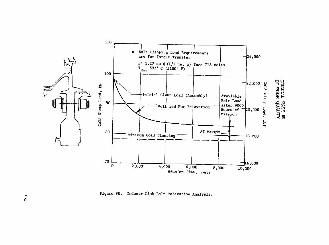
OE!Z!:!P.L PAG
E 1s O
F POO
R Q
UA
LITY
Co
ld Clamp Load, lbf
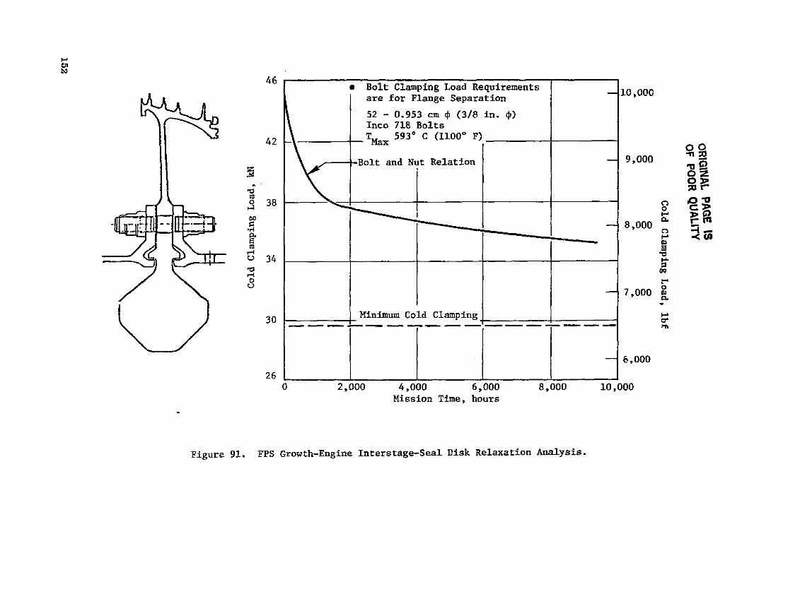
*
Figure 91. FPS Growth-Engine Interstage-Seal Cisk Relaxation Analysis.
10,000
9,000
8,000
7,000
6,000
Bolt Clamplng Load Requirenents are for Flange Separation
52 - 0.953 cm 4 (3/8 in. $) Inco 718 Bolts
593O C (1100" F)
B o l t and Nut Relation
Mission T i m e , hours
1
-
-
- I
Minimum Cold Clamping -----------------
-
-
0 2,000 4,000 6,000 8,000 10,000
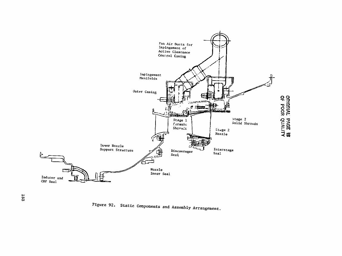
OR!G
!NAL PAGE IS
OF POOR Q
UA
LITY

s l o t t e d from the inner edge and t o r e l i e v e thermal s t r e s s and t o reduce the e f f e c t of shroud growth. It i e faced on forward and a f t s idee by t rapped , 360' sea l p l a t e s t h a t a r e f r e e to grow r a d i a l l y independent of the s t r u c t u r a l ring, &tween these s e a l p l a t e s and moving with them a r e hollow r i v e t e le - ments t h a t meter the flow of compreeaor-discharge a i r used t o cool the Stage 1 shrouds.
The predominant component of s t r e s s i n the casings i s thermally induced. The extremes of the s t r e s s range occur during takeoff t r a n s i e n t s and while the ACC syatem i s in opera t ion a t maximum climb and maximum c r u i s e condi t ions , Figure 93 shows various stresses and temperature with the correepondi.ng LCF 1 i f e a t d i f i e r e n t l oca t ions,
The ma te r i a l se lec ted f o r t he HPT cas ings t o meet the l i f e requirement of 36,000 f l i g h t cyc l e s i n an FPS des ign is Direct Age Inco 718 (DA718). This is a newly developed ma te r i a l under eva lua t ion of process c a p a b i l i t y and component performance; LCF i s up t o 10 t imes t h a t of s tandard Inco 718. The f ac to r of c y c l i c l i f e advantage of DA7i8 over s tandard Inco 718 v a r i e s with temperature and s t r e s s l e v e l , but it is s u f f i c i e n t to provide g r e a t e r than 50,000 cyc le s of LCF life a t a l l p o t e n t i a l l y s t r e sa - l imi t ing loca t ions .
The ou te r a x i a l support f o r the Stage 1 nozzle had ade3uate LCF l i f e us ing standard Inco 718, The shroud support is made of Rene 41. ~ e n g 41 provides an add i t i ona l 111' C (200" F) margin over Inco 718 t o the knee of i t 8 s t r eng th curve.
5 . 2 . 2 . 2 Stage 1 Nozzle Support
The Stage 1 inner noz5le support conf igura t ion is shown in Figure 94, The mater ial i s forged Rene 41, welded and machined t? the des i r ed contour. For the FPS base engine, t h e end f langes would b5 Rene 41 forgings; the remaining structure would be f ab r i ca t ed from Rene 41 sheet metal f o r reduced c o s t .
The nozzle-support r e a c t i o n loads o r i g i n a t e from the loads due t o a i r - foil gas Loading and from t he inner seal. The Stage 1 nozzle segments a r e bol ted t o the a f t f lange f o r vane-structure support and fo r proper vane-flow- path loca t ion . The discourager s e a l and inner s e a l mounting systems are a l s o supported from this component.
Load t r a n s f e r t o the compressor o u t l e t guide vane (OGV) is provided by sixty-four 0.953 cm (3 /8 in . ) diameter b o l t s fastened t o the forward f lange and OGV f lange.
The support s t r u c t u r e was analyzed based on d i f f e r e n t i a l p ressure across t h e wall , vane gas loads , and ou te r axial-support loads. An LCF life analysis based on t he worst condi t ions , 40 seconds i n t o hot-day t akeo f f , i nd i ca t e s t he s t r u c t u r e i s capable of meeting the ob jec t ive l i f e of 36,000 cycles .
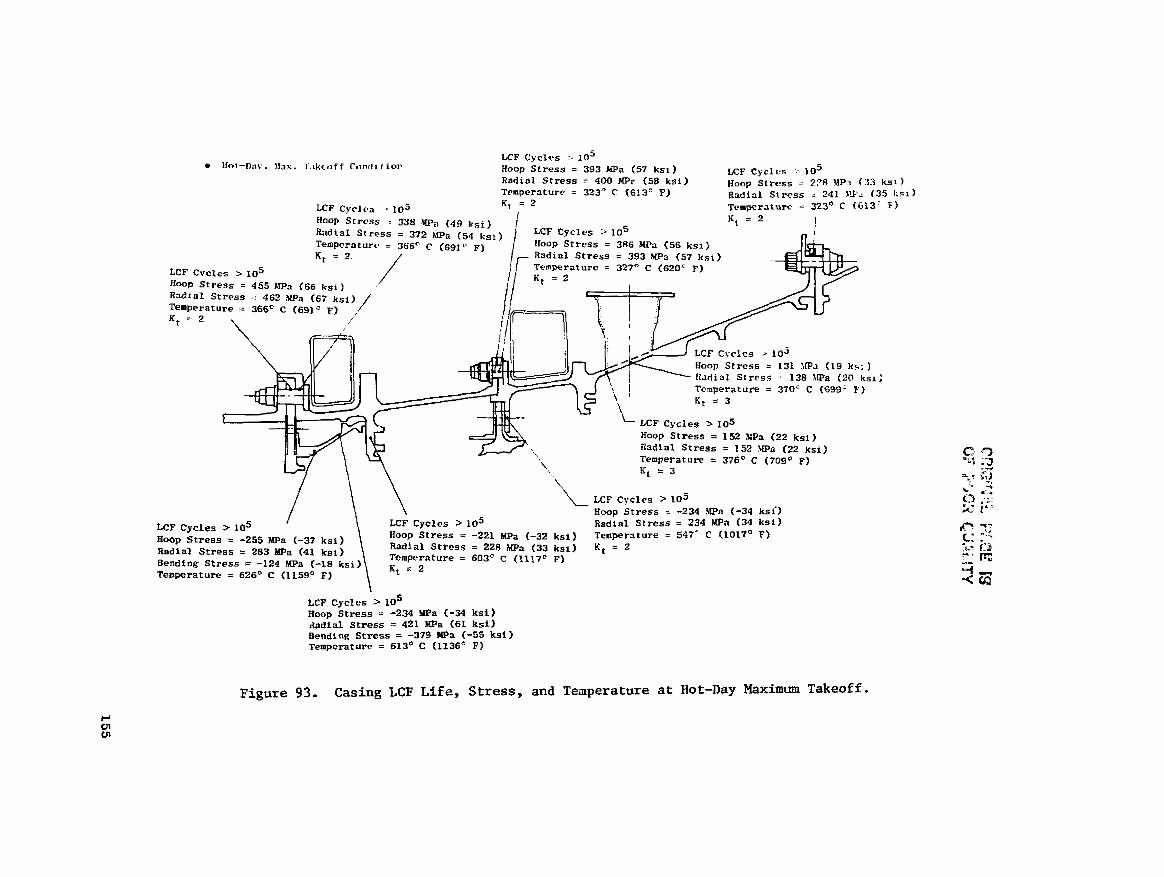
* Hot-l)nv. \la.;. lakcoff Cc~nrlr r ior LCF Cycles -- lo5 HOOP Stress = 393 m a (57 ks i 1 LCP cycles :- 105 Radial Stress = 400 MPP C58 ksi) HOOP st cess = 223 M P t 33 k s l ) Temperaturr = 323" c (61ZC F) Radial Stress = 241 IPa (35 J;r
.5 K, = 2 Temperature = 323' C (613' F)
38 ma (49 Bsi) J Kt = 2 . - ,-- _ . 1 LCF C O F I ~ . e :- 1 n5 I LCF C y c l r a - 10 Hoop Strcss - 3 RadiaL Stress = ,., .,, (34 R~~ --- - > - - b e -- Tem~eratur~ = 366O c (691 F) Hoop Stress = 386 UPQ (56 ksi) K t = 2 / ,- Radlnl Stress = 393 MPa (57 k s ~ )
/ j l Temperature = 327- C (620' F) LCF Cvcles 3 lo5 -- I fWP ~ t r e s s = 455 ~PIP~ (66 ksi) ' / Rdinl Stress = 462 $Pa (67 ksi) Temperature = 366O C (691' F) Kt = 2 i
/
j , e LCF C y c l c s -. 105 1 - Hoop Stress = 131 SIPa (19 k3: )
I Radial Stress - 138 >Pa (20 k c - . .--, Temperature = 37nC C (699' F) K, = 3
- \- LCF Cycles 105
Hoop Stress = 152 NPa (22 ksi) Radial Stress = 152 W a (22 ksi) Temperature = 37Ga C (709' F) ', Kt = 3
LCF cycles 105 Hoop Stress = -234 .Wa (-34 ksi ' )
LCF Cycles > la5 LCF Cycles > 105 Radial stress = 234 -a (34 ksi)
Hoop Stress = -255 MPa (-37 ksi) Hoop Stress = -221 Mpa (-32 ksi) Temperature = 547' C (1017C F)
Radinl Stress = 283 m a (42 ksi) Radial Stress = 228 h[Pa (33 ksi) K t = 2 Temperature = 603' C (1117" F) Bending Stress = -124
Temperature = 626' C (1159' F)
LCF Cycles > lo5 Hoop Stress = -234 MPa I-34 ksi) b d i a l Stress = 421 @a (61 ksi) Bending Stress = -379 ma (-55 ksi) Temperature = 613' C (1136' F)
Figure 93. Casing LCF Life, Stress, and Tesperature at Hot-Day Maximum Takeoff.

ORIGINAL PAGE IS OF. POOR QUALITY
40 Seconds into Takeoff , +50° C (222' F) Hot Day
Ren6 41 0utc.r
LCF L i f e Y36,000 Cyclesl
A x i a l G ~ B Load Aft Flange Stress: 1034 W n (150 ksi) 577O C (1070' I?)
Uiscourager Seal 1372 kPa (199 psi ) A
758 kPn (110 p s i )
.d Stress: 310 Ml?a (45 ksi 538' C (1000° F
Stress: 296 MPa (43 k s i ) 482' C (900' F)
Inner Seal
'Weld Stress: 296 MPn (43 Rsi) 666' C (1230° F)
rorward Flange , Connection to Compressor QGV/~iffuser, Stress: 359 MPn (52 ksi)
53B0 C (100o0 F)
Figure 9 4 . FPS Growth Engine Inner Nozzl,? Support.

The inducer and p i s t o n ba lance seal shown i n F i g u r e 95 s e r v e s t h e follow- i n g f u n c t i o n s :
Con ta ins the inducer /a i r -expander system t h a t p rov ides the a i r for c o o l i n g Blade 1 and Blade 2.
Reduces CDP l eakage through t h e forward-seal arrangement: w i t h the compressor balance p i s t o n seal d i s k (CUP l eakage) bypass.
r T r a n s p o r t s CDP l eakage through bypass tubes . Th i s a i r i s then used f o r purging t h e c a v i t y formed between Nozzle : and Blade 1 a t t h e i n n e r f lowpa t h . P r o v i d e s a b o l t s h i e l d and reduces t h e b o l t temperature caused by t h e CDP a i r l eakage . The b o l t t h e r e f o r e is exposed t o lower ternper- a t u r e s , the reby r e q u i r i n g a s m a l l e r b o l t s i z e for the same load requ i rements , a f t e r r e l a x a t i o n e f f e c t s a r e cons ide red .
The i n d u c e r - s t r u c t u r e s t r e s s a n a l y s i s was performed f o r 40 seconds i n t h e hot-day t a k e o f f c o n d i t i o n s . LCF l i f e r e s u l t s a r e shown i n F i g u r e 96. Based on the m a t e r i a l s t r e n g t h d a t a f o r R e d 41 and Inco 903A, the LCF l i f e objec- t i v e of 36,000 cyc les is reached.
5.2.2.3 S t a g e 1 Nozzle
The Stage 1 n o z z l e , shown a s an exploded view i n Figure 9 7 , c o n s i s t s o f a brazed a i r f o i l - t o - b a n d assembly. The a i r f o i l des ign c o n s i s t s of 46 i n d i v i d u a l aerodynamical ly shaped vanes manufactured from MA754 m a t e r i a l . Two a i r f o i l s are brazed i n t o each WR-M-509 m a t e r i a l band segment f o r a t o t a l of 23 seg- ments. A d d i t i o n a l f e a t u r e s o f t h e d e s i g n can be s e e n i n F igure 97 and i n c l u d e impingement i n s e r t s f o r improved a i r f o i l c o o l i n g end inner - and outer-band impingement c o o l i n g . Flowpath s e a l s a r e used between band segments t o reduce coo l ing-a i r leakoge a long t h e l e n g t h of t h e segments.
The S t a g e 1 nozz le d e s i g n mechanical f e a t u r e s a r e shown i n Figure 98. The a i r f o i l c o o l i n g is nccomplished by forward and a f t impingement i n s e r t s . The two c a v i t i e s formed by t h e i n s e r t s a r e s e p a r a t e d by a s l a n t e d r i b . The forward i n s e r t is placed i n t o t h e a i r f o i l c a v i t y from the inner f lowpath and b razed t o t h e a i r f o i l a t that end. The a f t i n s e r t i s placed i n t o t h e a f t c a v i t y from t h e o u t e r f lowpath and brazed a t t h e outer end of t h e a i r f o i l .
The 23 segments a r e b o l t e d t o t h e i n n e r nozz le suppor t by a t o t a l of 46 b o l t s . (Each segment c o n t a i n s two b o l t s . ) A p i n i s l o c a t e d on one end of t h e band flange and i s used f o r r a d i a l and c i r c u n f e r e n t i a l p o s i t i o n i n g o f t h e segment t o m a i n t a i n the p roper f lowpath con tour .
The i n n e r and o u t e r band segments a r e c a s t from MAR-M-509 m a t e r i a l , The bands c o n t a i n compattmentized c a v i t i e s f o r improved impingement and f i l m cool- ing. The i n n e r and o u t e r bands have i n t e g r a l g u s s e t s t o improve t h e a i r f o i l - to- f lange load d i s t r i b u t i o n .
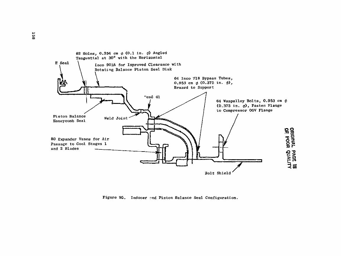
62 Holes, 0.254 cm d'(0.1 in. @) Angled TangentXal at 30° with the Horizontal
E Sea l
\ Into 903A for Improved Clearance w i t h Rotating Balance Pistan Seal D i sk \ .
64 Inco 718 Bypass Tubes, 0.953 cm (0.375 i n . @I, Brazed t o Support
64 Waspalloy Bolts, 0.953 c m (0 .375 i n . d), Fasten Flange
Piston Balance Weld J o i n t Aoney comb Seal
80 Expander Vanes for A i r Passage to Cool Stages 1 and 2 Blades
B o l t Sh ie ld /
Figure 95. Inducer :and Piston Balance Seal Configurat ion.
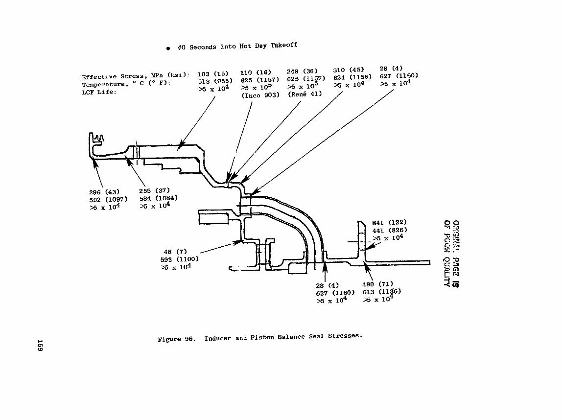
O?;GIN.?? PA
GE IS
OF
YGO
R Q
UA
LITY

ORlGlNAL PAGE IS OF POOR QUALITY
Figure 97. Stage 1 Vane Manufacturing.

Coolant Air Fe t o A f t Insert
Slanted Rib for Increased Inlet Area for Inserts
Gusset
4- Segmented A i r Cavity Discourager Seal
cornpartimentized Impingement Band Y late
Bolts Recessed in Seal for Reduction - in Windage Losses
Figure 98. Stage 1 Nozzle Design Features.
The nozz le f l a n g e , l o c a t e d on the i n n e r band, was analyzed based on t h e maximum induced moments due t o g a s load and a l s o due t o t h e inner and o u t e r ax ia l -euppor t mismatch o c c u r r i n g d u r i n g eng ine t r a n s i e n t o p e r s t i o n . Maximum f l a n g e s t r e s s e s occur a t 15 seconds a f t e r t a k e o f f . The induced f l a n g e bending stress, a s shown i n F igure 99, i s w e l l below t h e 269 MPa (39 k s i ) ( 3 0 ) 0.2% y i e l d a l lowable s t r e s s f o r MAR-M-509.
The a f t - c a v i t y , s u c t i o n - s i d e wall i s s u b j e c t e d t o a h igh p r e s s u r e d i f f e r - e n t i h l t h a t t e n d s t o induce b u l g i n g of the w a l l . This "bal looningt ' e f f e c t changes t h e aerodynamic contour and r e s u l t s i n l o s s o f t u r b i n e e f f i c i e n c y . The vane d e s i g n t h e r e f o r e c o n s i d e r s the p o s i r i o r i s o f t h e r i b ( t h e r i b a l s o s e p a r a t e s t h e forward and a f t a i r f o i l c a v i t i e s ) so t h a t the panel stresses a t temperature w i l l be minimum. The MASS a n a l y s i s was used t o determine the p a n e l s t r e s s e s based on the o r t h o t r o p i c modulus p r o p e r t i e s o f the MA754 a i r - foil a l l o y , The wall was g e o m e t r i c a l l y modeled a s panel s e c t o r s . The r e s u l t - ing c a l c u l a t e d d e f l e c t i o n based on hot-day t a k e o f f o p e r a t i o n is shown i n Fig- u r e 100. A s c a n be seen from the c u r v e , t h e r e s u l t i n g bu lge of on ly 0.05 mm (0.002 i n . ) fo r 600 hours o f maximum eng ine t akeof f c o n d i t i o n s i s more than adequa te t o meet engine p a r t r e q u i r e m e n t s .
The S tage 1 vane a i r f o i l LCF l i f e - l i m i t i n g l o c a t i o n was determined t o be t h e 65% span. The LCF l i f e i s de te rmined by a n a l y z i n g the t o t a l l o c a l s t r a i n r a n g e occur r ing between maximum takeoff t r a n s i e n t through a 2-minute t akeof f and t h r o t t l e chop t o i d l e . The t o t a l l o c a l s t r a i n i s t h e r e f o r e a f u n c t i o n of t h e induced the rmal s t r e s s e s o c c u r r i n g during t h e s e two o p e r a t i n g f l i g h t con- d i t i o n s , p l u s t he mechanical s t r e s s e s . The mechanical s t r e s s e s a r e the r e s u l t of gas load ing and moment induced i n t h e a i r f o i l due to t h e a x i a l thermal growth mismatch o c c u r r i n g between the i n n e r and o u t e r rlozzle suppor t . ' h e mistaatch induces a n n ~ . i a l load a t t h e o u t e r s u p p o r t w h i c h r e s u l t s i n a moment i n the a i r f o i l .
F igure 101 shows the c a l c u l a t e d LCF l i f e f o r the Scage 1 vane a i r f o i l sec- t i o n a t the lirniti?~ l o c a t i o n s . The eng inc c o t ~ d i t i o n s u s e d were based on a maxitourn gas peak t empera tu re p r o f i l e wi th Eul: e n g i n e - d e t e r i o r a t i o n parameters and a t maximum hot-day t akeof f c o n d i t i o n s . The a i r f o i l t empera tu re assumpt ions a r e t h e r e f o r e based on maximum-severity e n g i n e c o n d i t i o n s .
The maximum peak gas t empera tu re of 1740" C (31k3-F) i s based on the a v e r a g e t empera tu re g a s profi1.e p l u s t h e e f f e c t s of the combustor p a t t e r n f a c t o r . Aversge gas p r o f i l e t empera tu re i s a f u n c t i o n o f t h e c y c l e d a t a . A temperature of 7 8 " C (140" I?) was added Lo t h e p r o f i l e va lue 3 f o r d e s i g n con- s i d e r a t i o n ~ . Th i s adder t a k e s i n t o account engine-to-engine v a r i a t i o n s , de te - r i o r a t i o n s , c o n t r o l t o l e r a n c e s , and o t h e r known paramete r s t h a t can v a r y w i t h i n each engine sys tem. ,
5.2.2.4 S t a g e 2 Nozzle
The S tage 2 nozzle shoyn i n F i g u r e 102 c o n o i s t s o f 48 ~ e n g 150 a i r f o i l s b r a s e d a s p a i r s i n t o 24 Rene 80 i n n e r and o u t e r bands. The s e l e c t i o n of Rene 150 m a t e r i a l f o r t h e a i r f o i l provided i n c r e a s e d LCF and r u p t u r e s t r e n g t h
QREG!NAE PAGE IS OF POOR QUALITY
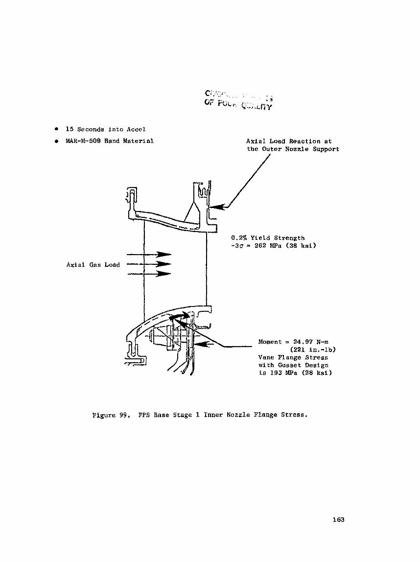
15 Seconds into Accel
0 MAR-M-509 Band Material
Axi a1 Gas Load
A x i a l Load Reaction a t the Outer Nozzle Support
3
L- T - ~ L ~ 0.2% -30 = Y i e l d 262 MPa Strength (38 ksi)
A-
Moment = 24.97 N-m (221 in.-lb)
Vane Flange Stress w i t h Gusset D e s i g n is 193 MPa (28 k s i )
Figure 99. FPS Base Stage I Inner Nozzle Flange Stress.
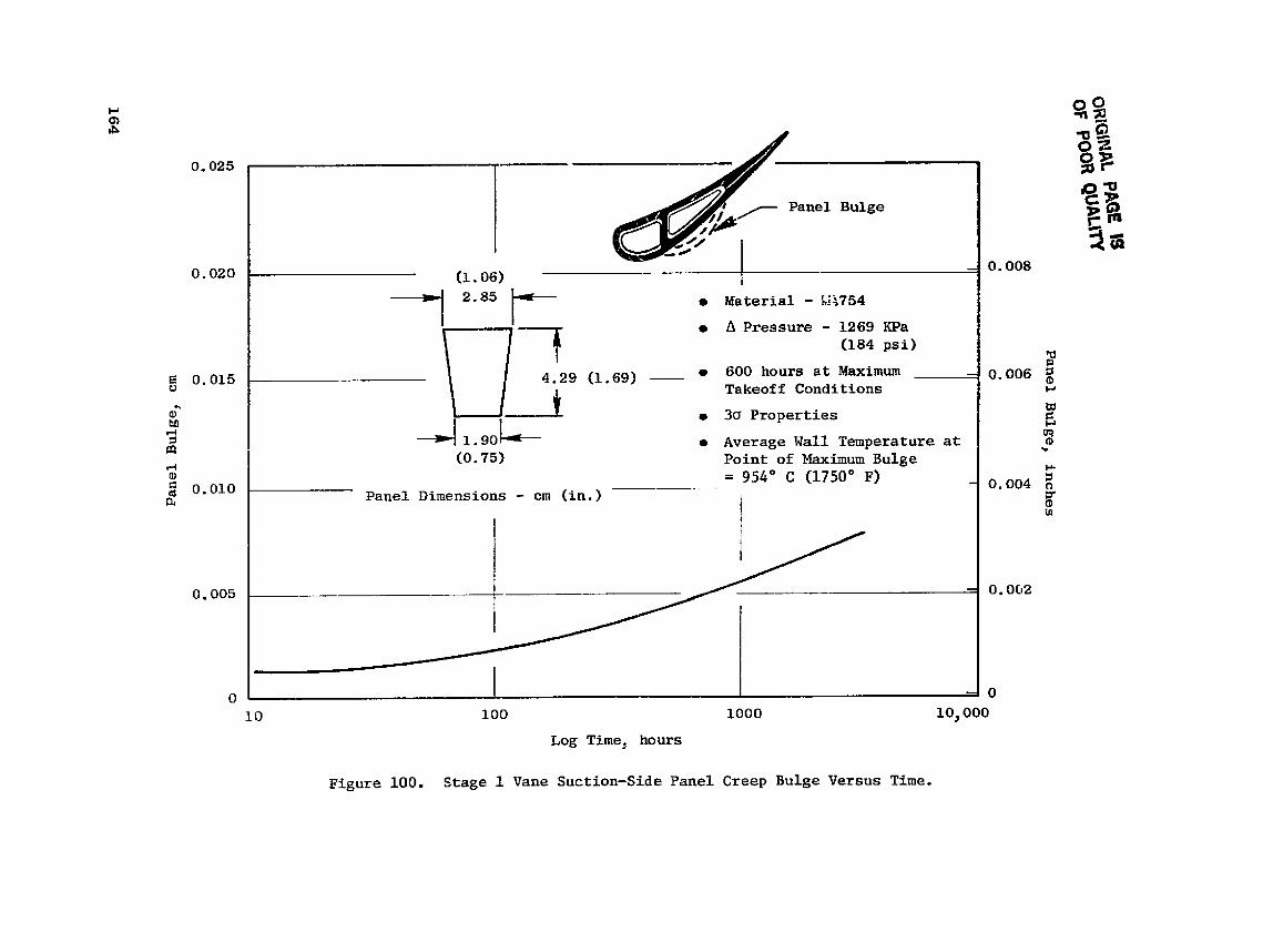
Pa
nel
Bu
lge,
inch
es

' . I ORKL + - a 7 - *
OF POOR Q U k ~ l i
J
Temperature, " C (O P I : 1027 (1881) 866 (1590) 878 (1612) Stress, MPa ( k s i ) : 386 (56) 510 (74) 414 (60)
310 (45) 386 (56) 379 (55)
I 842 (15481 441 (64)
XO ,000
MA754 Material Transient Conditions: Idle to Max. Takeoff and Back t o Idle
Figure 101. Stage 1 Nozzle A i r f o i l LCF L i r e at 65% Span at Maximum Takeoff Condi t ion (Table IX).

,Nozzle flange Bolted to Outer Caaing
Forward Gummetr to Improve Airfoil h a d Redircribution
A f t Gussets
Floupath Hour-' glarr Sesla
48 R e d 150 Airfoi ls I I
I I Re& 150 Airfoil Brazed I I to R e d 80 Bands (-0 n t r t o n s ~ h n e
I I I I
A i r EoA Capabl by 4%
Six
Ylcvpath Hour-
;l/Band Deaign ;e of Do Change
One 0 .635 cm +(I14 in . 4) Waspalloy Fastener/Segment
No Holes or Slots for Improved kindage Coverage
Six Inner Dfscoura~er
Forward Seals Six Interstage Flat Seals for Reduced
purge Leakage Flow
Figure 102. Stage 2 Nozzle Design Features.
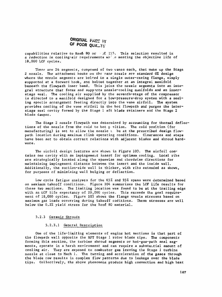
ORlGlNAL FAEL' (5' OF POOR QUAL;TIP
c a p a b i l i t i e s r e l a t i v e t o Hens 80 or .~'t 1ti5. This s e l e c t i o n r e s u l t e d i n a r e d u c t i o n i n cooling-air requ i rements wn .' .e meeting t h e o b j e c t i v e l i f e of 18,000 LCF c y c l e s .
Tllert? a r e 24 segments, composed of two vanes each , t h a t make u p the Stage 2 nozz le , The at tachment hooks o n tllc vane nozz le are s tandard GE d e s i g n where t h e nozzle segments a r e to l r . ed t o a s i n g l e ou te r -cas ing f l a n g e , eimply suppor ted a t a forward hook, and b o l t e d t o g e t h e r a t an i n t e g r a l manifold benea th the f lowpath inner band. Th is j o i n s t h e nozz le segments i n t o an i n t e - g r a l s t r u c t u r e t h a t forms and supp .>r t s nozzle-cool ing manifolds and a n inner- s t a g e sea l . The coo l ing a i r s u p p l i e d by t h e seventh-s tage of t h e cGmpressor i s d i r ec t ed t o a manifold des igned f o r a Low-pressure-drop system wi th a sea l - i n g spoo l ie arrangenent feed ing d i r e c t l y i n t o t h e vane a i r f o i l . The system p r o v i d e s c o o l i n g of the vane a i r f o i l i n t h e h o t f lowpath and purges t h e i n t e r - s t a g e sea l c a v i t y formed by t h e S t a g e 1 a f t b l a d e r e t a i n e r s and t h e Stage 2 b l a d e damper.
The Stage 2 nozzle f lowpath was determined by account ing f o r thermal de f lec - t i o n s of the n o z z l e from the c o l d t o h o t p, s i t i o n . The co ld p o s i t i o n ( f o r manufactur ing) i s s e t t o a l low t h e nozzle L b e a t t h e p resc r ibed des ign flow- path Location d u r i n g maximum c 1 imb o p e r a t i n g c o n d i t i o n s . C lea rances and s t e p s have been s e t t o o b t a i n c o r r e c t r e l a t i o n s wi th ad jacen t blades and shroud hard- ware .
The a i r f o i l des ign f e a t u r e s a re shown i n Figure 103. The a i r f o i l con- t a i n s one c a v i t y with an impingemeirt i n s e r t f o r optimum coo l ing . Local r i b s a r e s t r a t e g i c a l l y loca ted a l o n g the spanwise and chordwise d i r e c t i o n s f o r main ta in ing impingement d i s t a n c e between the i n s e r t and t h e i n s i d e wall. A d d i t i o n a l l y , t h e suc t ion-s ide w a l l i s t h i c k e r , wi th r i b s extended a s shown, for purposes o f minimizing w a l l bu lg ing o r d e f l e c t i o n .
Low c y c l e f a t i g u e analyses For the 65% and 95% spans were determined based on maximum t a k e o f f c o n d i t i o n s . F igure 104 summarizes t h e LCF l i f e r e s u l t s fo r t h e s e two s e c t i o n s . The l i m i t i n g l o c a t i o n was found t o be a t t h e t r a i l i n g edge w i t h an LCF l i f e expectancy o f 20,000 c y c l e s . Th i s exceeds the g o a l r equ i re - ment of 18,000 c y c l e s . Figure 105 shows t h e f l a n g e nozzle s t r e s s e s based on maximum gas l o a d s occur r ing d u r i n g t akeof f c o d i r i o n s . These s t r e s s e s a r e w e l l below the 0.2% y i e l d s t r e s s f o r t h e Renk 80 m a t e r i a l .
5.2.3 Ceramic Shrouds
5 .2 .3 .1 Genrral D e s c r i p t i o n
One of t h e l i f e - l i m i t i n g e lements of eng ine h o t s e c t i o n s is t h a t p a r t of the flowpath w a l l oppos i t e t h e HPT S tage 1 r o t o r b lade t i p s . The componentc forming t h i s s e c t i o n , t h e t u r b i n e shroud segments o r hot-gas-path s e a l seg- ments , opera te i n a harsh enlrironment and can r e q u i r e a subs ta r . t i a1 amount o f c o o l i n g a i r . Tiley a r e exposed t o combustor gas l e a v i n g the S tage 1 t u r b i n e n o z z l e a t c l o s e t o Mach 1. The t u r n i n g and a c c e l e r a t i o n of the g a s e s through the blade row r e s u l t s i n complex flow p a t t e r n s due t o leakage over the b l a d e t i p s . Col lectCvely , the above phenomena produce high convec t ion and h igh heat

ORIG\NAL PAGE IS OF POOR QUALlTY
Single Insert Impingement
Figure 103. Stage 2 N G Z Z ~ ~ Airfoil Design Features.
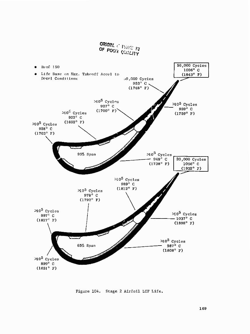
tlclnf 1 50 1006" C
a L i f e Bnsc cln hfax. Takvoff Acccl to (1843' F) nccr l Cond i l . i o n s .19,000 Cycles
953" C , [174a0 F)
95% Span NA
y r v L y G l e Y
928' C
948' C 1 20,000 Cycles I
989' C - - - - - - .
yo5 C y c l e s 1037' C
Figure 104. Stage 2 A i r f o i l LCF L i f e .
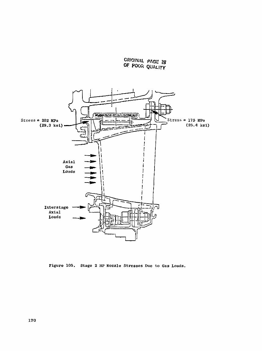
Stress t
Interstage Axial.
= 175 MPa (25.4 kai)
Figure 105. Stage 2 HP Nozzle Stresses Due to Gas Loads.

load over a r e l a t i v e l y l a r g e s u r f a c e a r e a . The shrouds exper ience engine v i b r a t i o n and p r e s s u r e f l u c t u a t i o n from p a s s i n g b lades . They undergo thermal cyc l ing from s t a r t / s t o p and power-se t t ing changes, I n a d d i t i o n , u n l i k e o t h e r cooled s u r f a c e s exposed t o t h e s e s e v e r e c o n d i t i o n s , t h e shroud s u r f a c e must be abltl to s u r v i v e b lade rubs . This s e v e r l y impacts c o o l i n g c o n t r o l ; c o o l i . ~ g c o n t r o l i s a f f e c t e d by w a l l t h i c k n e e s and f r e q u e n t l y depends on m a i n t a i n i n g numerous small-diameter-fi lm-hole p a t t e r n s .
En t h e p a s t , an e f f e c t i v e way o f coping with a l l of t h e s e c o n d i t i o n s and requirements h a s been through the u s e o f m e t a l e u r f a c e s , e i t h e r i n a high- d e n s i t y c a s t o r wrought i'orm or i n a lower d e n s i t y s i n t e r e d oi hot-pressed form. The h i g h thermal c o n d u c t i v i t y of m e t a l lends i t s e l f t o m a i n t a i n i n g a c c e p t a b l e s u r f a c e t empera tu res , whether wi th f i l m c o o l i n g o r w i t h o n l y back- s i d e impingement coo l ing , 3n the o t h e r hand, t h e lower d e n s i t y d e s i g n s pro- v i d e a degree of a b r a d a b i l i t y t h a t c a u s e s Less b l a d e - t i p wear and h e l p s t o main ta in b e t t e r t i p c l e a r a n c e . The lower d e n s i t y s u r f a c e a l s o p rov ides a lower e l a s t i c modulus a n d , t h u s , c o n t r i b u t e s t o lower thermal stress. How- evel, , r e g a r d l e s s of t h e r n a t c r i a l cho ice , t h e s u r f a c e w i l l s t i l l reach h i g h temperatures and w i l l r e q u i r e meta l a l l o y s w i t h good, h igh- t empera tu re , oxi- d a t i o n r e s i s t a n c e .
As turbine i n l e t t empera tu res i n c r e a s e c o o l i n g - a i r requirements i n c r e a s e , and i t becomes i n c r e a s i n g l y d i f f i c u l t to m a i n t a i n t h e l o w surface t empera tu res necessary i n l o n g - l i f e a p p l i c a t i o n s . The a l t e r n a t i v e approach i s a new con- cept i n material i o r the surface exposed t o t h e hot-gas s t r eam. Ceramics p rov ide t h i s a l t e r n a t i v e . With s t a b l e - o x i d e ceramics , t h e o x i d a t i o n r e s i s - t ance is un l imi ted f o r a l l p r a c t i c a l purposes . Ln a d d i t i o n , a p p r o p r i a t e l y selected ceramics have l o w thermal c o n d u c t i v i t y and s e r v e t o reduce t h e amount of cool ing a i r r equ i red t o keep t h e s u p p o r t i n g m a t e r i a l s a t desired ternprTn- t u r e s . F u r t h e r , these ceramics have a low c o e f f i c i e n t o f thermal expansion which, a t t empera tu res above 1204' C (2200" F ) , r e s u l t i n a thermel expansion determined t o be c l o s e t o t h e expansion of t h e m e t a l l i c s u p p a r t . Plasma- sprayed z i r con ia has a l l o f t h e s e c h a r a c t e r i s t i c s .
5.2.3.2 Design and A n a l y s i s
The ceramic shroud de s ign shown i n F i g u r e 106 c o n s i s t s o f a plasma-sprayed, z i rconia /Y203 ce ramic , surface l a y e r i i ? t e g r a l l y bonded t o an o x i d a t i o n - r e s i s - t a n t , c a s t , Bene 77 backiug. T h i s backing p rov ides f o r a t tachment o f t h e shroud t o t h e suppor t s t r u c t u r e . The m e t a l back:-g h a s a peg a r r a y i n t e r f a c e t o provide mechanical anchor ing o r i n t e r l o c k i n g LO supplement t h e ceramic/ metal-backing bond adherence. N i C r A l Y is the bond coat , and a b lend c o a t of bond coat and t o p c o a t p r o v i d e s a t r a n s i t i o n layer.
The e f f e c t i v e n e s s of z i rcon ium ox ide a s a s u r f a c e l a y e r arises from very low thermal c o n d u c t i v i t y , chemical s t a b i l i t y , and h i g h m e l t i n g p c i n t . For t h e NiCrAlY bond c o a t , long-term d u r a b i l i t y r e q u i r e s t h a t t empera tu re be Limited t o about 982" C C1800" F ) . This w i l l p reven t o x i d a t i o n of t h e bond coat (wi th a s s o c i a t e d volume change) and w i l l p reven t i ts d i f f u s i o n i n t o t h e base meta l . I n t h i s way, t h e i n t e g r i t y o f t h e bond joint i s ma in ta ined .

ORlGlMAL PAGE IS OF POOR QUALITY
,/ - *-. Flnwpnth Side
Surface Ceranric: Zirconie (6-m, y203)
Blend Cuat
Commercial Experience - 1980: 625 "c" Cycles, 166:4G Endurance Hours
1979: 65: 22 Performance Tes t i ng ; Hours
- Figure 106. Ceramic Shroud.
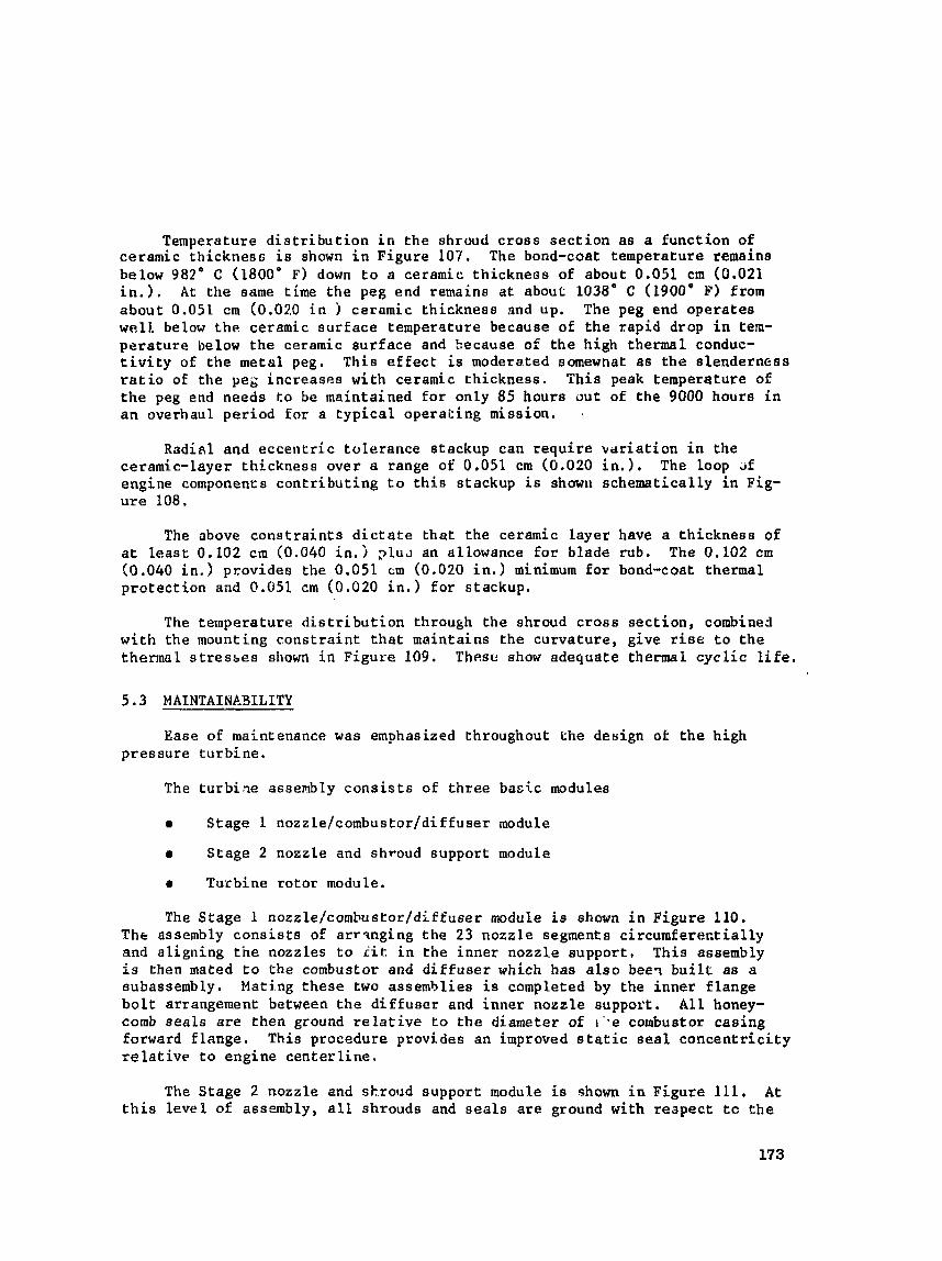
Temperature d i s t r i b u t i o n i n t h e shroud c r o s s s e c t i o n a s a f u n c t i o n of ce ramic t h i c k n e s s is shown i n F i g u r e 107. The bond-coat temperature remains below 982' C (1800' F ) down t o a ceramic th ickneos of about 0.051 cm (0.021 i n . ) . A t the same time the peg end remains a t about 1038" C (1900' F) from a b o u t 0.051 cm (0.02.0 i n ) caramic t h i c k n e s s and up. The peg end o p e r a t e s well below t h e ceramic ourface temperature because of t h e rap id drop i n tem- p e r a t u r e below t h e ceramic s u r f a c e and kecause of t h e h igh thermal conduc- t i v i t y of t h e m e t a l peg. T h i s e f f e c t is moderated somewhat as t h e slenderness r a t i o of t h e peg i n c r e a s e s w i t h ceramic t h i c k n e s s . T h i s peak temperature of t h e peg end needs t o be mainta ined f o r on ly 85 hours o u t of t h e 9000 hours i n a n overhaul p e r i o d for a t y p i c a l operak ing miss ion . .
Radial and e c c e n t r i c t o l e r a n c e s t ackup can require v d r i a t i o n i n t h e ceramic- layer t h i c k n e s s o v e r a range of O.051 cm (0.020 in.), The loop ~f engine components c o n t r i b u t i n g t o t h i s s tackup i s showlk s c h e m a t i c a l l y i n Fig- ure 108.
The above c o n s t r a i n t s d i c t a t e t h a t t h e ceramic l a y e r have a t h i c k n e s s of a t leas t 0.102 cm (0.040 in.j p l u ~ an a l lowance f o r b lade rub . The 0.102 cm (0.040 i n . ) p r o v i d e s the 0.051 cm (0.020 i n . ) minimum f o r bond-coat thermal p r o t e c t i o n and 0.051 cm (0.020 i n . ) f o r s t ackup .
The t empera tu re d i s t r i b u t i o n through t h e shroud c r o s s s e c t i o n , combined w i t h t h e mounting c o n s t r a i n t t h a t ma in ta ins t h e c u r v a t u r e , give r i s e t o t h e thermal s t r e s s e s shown i n F i g u r e 109. Thesc! show adequa te thermal cyclic l i fe .
Ease of maintenance was emphasized throughout the design of t h e high p r e s s u r e t u r b i n e .
The tu rb i ,qe assembly c o n s i s t s of three b a s i c modules
9 Stage 1 nozzle/combus t o r / d i £ f u s e r module
r S t a g e 2 nozzle and shroud suppor t module
9 T u r b i n e rotor module.
The S t a g e 1 nozzle/combustor/dlffuser module is a h m n i n F i g u r e 110. The assembly c o n s i s t s of a r r q n g i n g t h e 2 3 nozz1,e segments c i r c u r n f e r e n t i a l l y and a l i g n i n g the nozzles t o iit i n t h e i n n e r n o z z l e s u p p o r t , T h i s assembly is then mated t o the combustor and d i f f u e e r which h a s a l s o bee? b u i l t a s a subassembly. Mat ing t h e s e two assembl ies i s completed by t h e i n n e r f l a n g e b o l t arrangement between t h e d i f f u s e r and inner nozzle support . A l l honey- comb s e a l s are t h e n ground r e l a t i v e t o t h e diameter of r ' . e combustor c a s i n g forward f l a n g e . This procedure p rov ides an improved s t a t i c s e a l c o n c e n t r i c i t y r e l a t i v e t o engine c e n t e r l i n e .
The S t a g e 2 nozz le and shroud suppor t module is shown i n F i g u r e 111, A t t h i s level of assembly, a l l shrouds and s e a l s a r e ground wi th r e a p e c t t o the
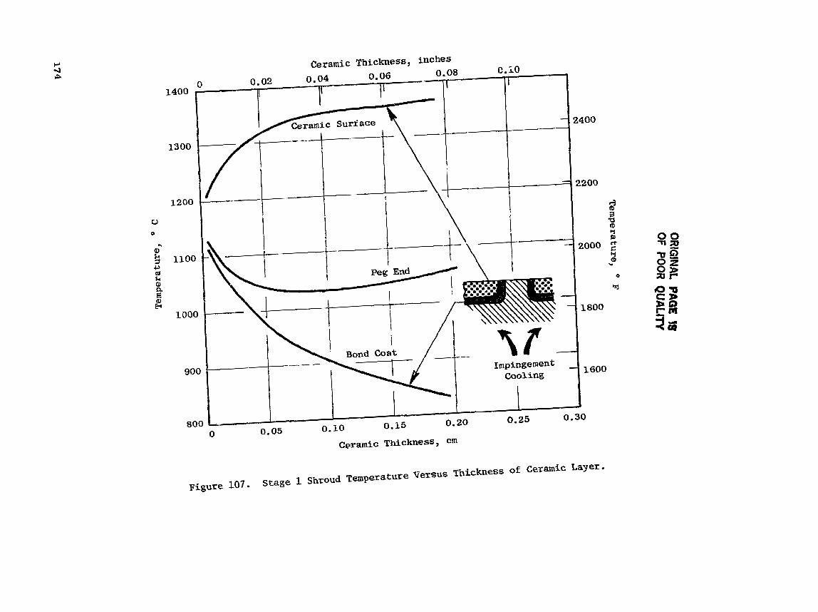
ORIG
INAL PA
W !S
OF PO
OR Q
UA
LITY
Tem
peratu
re, * F
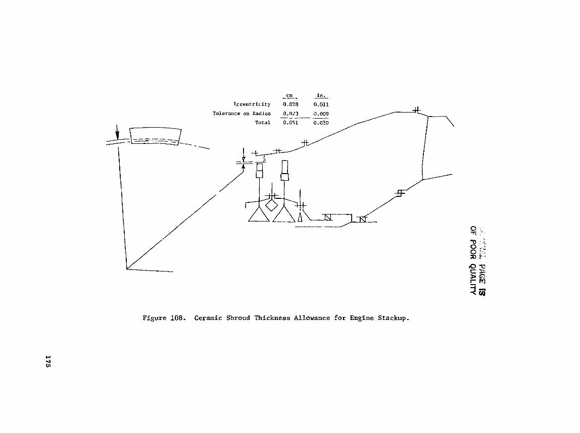
' .
&~
*.
t'
lt
..I.
..:.;-.I* PA
GE 1s
OF B
OO
R Q
UA
LITY

ORlGlNAL PPiGE FS OF POOR QUALITY
L i f e : >lo5 Cycles Max. Stress: 179 ! ? a (26 hsi) Average Temperature: 743' C (1370" F)
~ 0 5 C y c l e s 221 MPa (32 ksi) 849O C (1560"
>lo5 Cycles 200 MPa (29 ksi) 871' C (1600' F)
Figure 109. Ceramic Shroud ~tress/~ife.

GM
j,>tNkL tiitC
i;l: IS
OF
POO
R QU
ALITY

ORIGINAL PAQC IS OF POOR QUALlTV
Nozzle and Shroud Support Cas ing
Stage 2 Shroud
Stage I Shrouds are Stage 2 Noxzle Ground at t h i s P o i n t to Minimize Radia l Stackup and Improve Concentricity I n n e r S e a l s arc Ground to
Improve Co~cer,tl i city
Figure 111. Stage 2 Nozzle and Shroud-Support Casing Module Assembly, Engine Level.

cas ing . T h i s g r i n d i n g o p e r a t i o n r e s u l t s i n reducing t h e r a d i a l s t ackup and thereby improving c o n c e n t r i c i t y r e l a t i v e t o t h e cas ing . Axia l and r a d i a l i n s p e c t i o n s a r e determined a t t h i s assembly l e v e l . These i n s p e c t i o n s a r e used i n determining r e l a t i v e c l e a r a n c e s between t h e static and r o t a t i n g components,
The t u r b i n e r o t o r module i s shown i n F igure 112, A t t h i s assembly level , t h e Stage 1 and 2 b lades have a l r e a d y been t i p ground whi le assembled i n t h e S t a g e 1 and 2 d i s k r . Balancing has a l s o been completed, The r o t o r i s balan- ced a t t h e two planes a s shown. The HP s h a f t and forward o u t e r l i n e r a r e bal- anced and i n s t a l l e d as p a r t of t h e compressor modute,
Engine l e v e l assembly f o r the HP t u r b i n e i s accomplished by i n s t a l l i n g t h e Stage l /c ,ombustor /di f fuser module i n t o t h e compressor c a s i n g . The t u r b i n e r o t o r i s then placed i n t o t h e engine assembly. Fas ten ing f o r the turbine ro to r assembly i s completed a t t h e HP s h a f t a f t f l a n g e b o l t i n t e r f a c e .
I n o r d e r t o i n s t a l l t h e S t a g e 2 n o z z l e and shroud module, t h e S t a g e 2 a f t b lade r e t a i n e r , b lades , aad dampers are removed f r m t h e r o t o r assembly. These components a r e match-marked p r i o r t o removal f o r reassembly i n t h e i r o r i g i n a l ba lance p o s i t i o n .
After S t a g e 2 nozz le module is assembled and f a s t e n e d t o the combustor a f t flar*ge, t he Stage 2 blades, daaper, and a f t b l a d e retainer a r e reassembled i n t h e i r o r i g i n a l p o s i t i o n ( o r i e n t a t i o n ) .
I n summarizing, for ease of m a i n t a i n a b i l i t y and disassembly two f a s t e n i n g joints wilL remove the whole t u r b i n e ( e x c e p t S t a g e 1 n o z z l e ) . I f t h e Stage 1 nozz le needs t o be removed, t h e inner n o z z l e suppor t f l a n g e a l lows ease of disassembly.
5.4 FPS ASSEVlLY WIGHT
A t u r b i n e weight summary f o r t h e FPS base engine i a shown i n Tab le XXIII.
Table X X I I P . FPS Weight Data Base.
1 Tota l Turbine
HPT S t a t o r
W T Rotor
kg
414
13%
282 r
2
Ibm
913
290
623
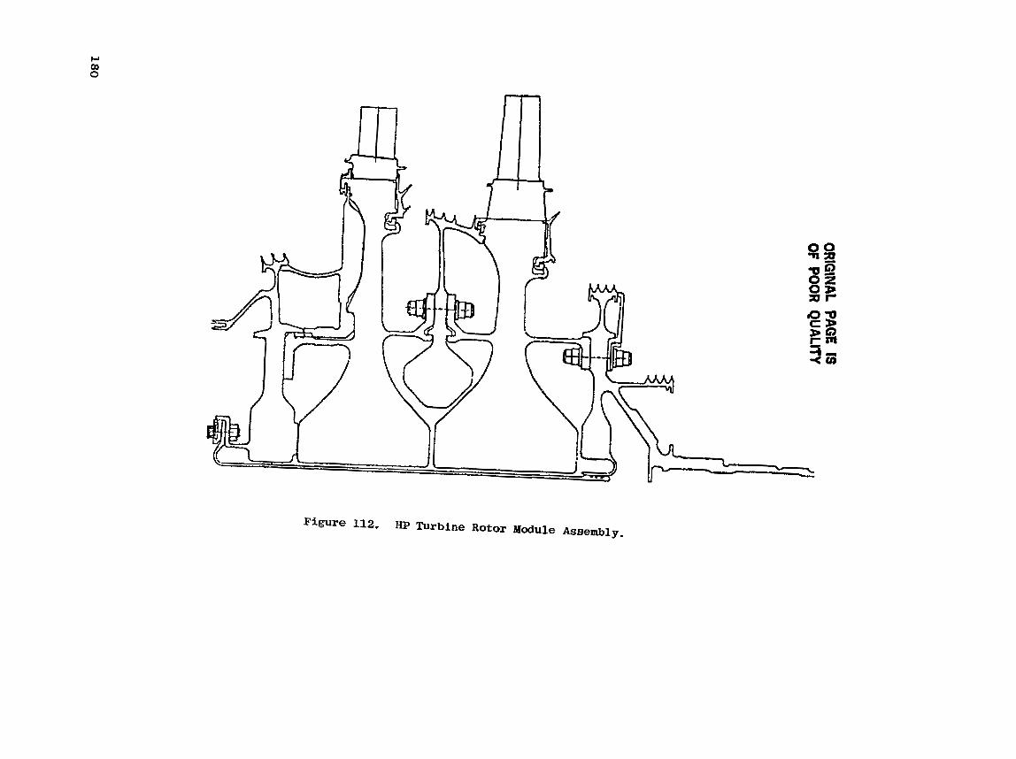
OR
IGIN
AL PAG
E IS OF
POO
R QU
ALlTV

REFERENCES
1. N e i t z e l , R.E. , Hirschkron, R . , and Johnston, R . P . , "Study of Turbofan Engines Designed f o r Low Energy C o a s ~ m p t ion," NASA-Lewis Research Center , CR-135053, 1976.
I* 2. Neitzel , R.E. , Hirschkron, R. , and Johns ton , R.P. , Study o f Unconven- t i o n a l A i r c r a f t Engines Designed for Low Energy Consumption,'' NASA-Lewis Research C e n t e r , CR-135130, 1976.
3 . Steinberger, C . A . , S t o t l e r , C.L., and N e i t z e l , R.E . , "Study of the C o s t and B e n e f i t s o f Composite M a t e r i a l i n Advanced Turbofan Engines,' ' NASA- Lewis Research Center, CR-134696, October 1974.
4 . Ross, E , W , , Johnston, R . P . , and N e i t z e l , R.E. , "Cost Benefit Study of Advanced M a t e r i a l s Technology for Aircra:; Turbine Engines," NASA-Lewis Research C e n t e r , CR-134702.
5 , H i l l e r y , R.V. and Johnston, R,P, , "Cost Benef i t Study of Advanced Mate r ia l s Technology for A i r c r a f t Turbine Engines," NASA-Lewis Research Cente r , CR-135235.
6. Johnstor,, R.P., Hirschkron, R . , Koch, C , C , , and Neitzel, R.E., "Energy E f f i c i e n t Engine - Pre l iminary Design and I n t e g r a t i o n Study," NASA-Lewis Research C e n t e r , CR-135.54.
SYMBOLS AND TERMS
A
ACC
Accel
AR
AW
BFM
CDP
CF6
D
do
Decel
D S
E
F
EB
f~
FADEG
FOD
FPS
Area, vane flow area; m2 ( i n 2 )
A c t i v e Clearance Control
Accelerat ion
Aspect Ratio = blade h e i g h t (h) /b lade Axial Width (AW)
A i r foil Axial Width, cm f in )
Backflow Margin: D i f f e r e n t i a l pressure betwet,! the spent impinge- ment air pressure and the gas-side pressure, [(+, - P Tg ) / P ~ g ] 100%
Brake horsepower
Velocity ava i l ab l e i n i s en t rop ic expansion of turbine inlet flow across t he group to t a l - to - s t a t ic pressure r a t i o , d s e c ( f t / s e c )
Compressor Discharge Plane, Compressor Discharge Pressure
General E l e c t r i c commercial turbofan engine family
Diameter; m , crn (in)
Airfoil throat dimension, cm ( in)
Decelerat ion
Di rec t iona l ly S o l i d i f i e d , Di rec t iona l S o l i d i f i c a t i o n
Energy Efficient Engine
Force, N ( l b f )
Frequency o f backward-traveling wave, Hz
Frequency of forward-traveling wave, Hz
Full Authority D i g i t a l Electronic Control
Foreign Object Damage
F l i g h t Propulsion Sys tern, Refers t o the f u l l y developed co ?f iguta- t i o n of the Energy E f f i c i e n t Engine which would be suitable f o r air- frame i n s t a l l a t i o n .

h
Ah
HCF
HIP
HP
HPT
ICLS
K t
a
L
LCF
LP
LPT
M
MXCR
N
NDT
ODs
OGV
P
PM
PVD
Y,'A
RZ
R2
sf c
SLTO
Sl
s 2
Heat Transfer Coeff ic ien t (W/m * * C ('F))
Energy ex t r ac t ion , kJ/kg (Btu/lbm)
High Cycle Fatigue
Hot 180s rat i c Press ing (pressed)
High Pressure
High Pressure T u r b i n e
In tegra ted Core /~ow Spool. The comp1e:e turbofan t e s t configuration of the ~ 3 ,
Streee Concentration Factor
Length, blade t i p ahroud overhang length; c m (in,)
Length, length of a i r f o i l ; crn ( i n . )
Low Cycle Fatigue
Low Pressure
Low Preasure Turbine
Mach nrlmber
Maximum cruise opera t ing point
Turbine speed, rpm
Nondestructive Tas t ing
Oxide Dispersion Strengthened
O u t l e t Guide Vane (compressor o r Turbine)
Pressure, Pa ( p s i )
Powder Metallurgy
Physical Vapor Deposit iort
Preb.*ht- . f r rea; S t r e s s k ~ a / m * (k s i / i n .2 )
Rotor 1
Rotor 2
Spec i f i c f u e l consumption, kg/N9hr (1bm/lbfghr)
Sea Level Takeoff
S t a t o r 1
S t a t o r 2
Total Temperature, Temperature; K (' B)

Ttb Re l a t i v e Blade Tot a1 Temperature
AT amb Ternperat~~e above ambient a t s t a n d a r d day c o n d i t i o n s
U Rotor t a n g e n t i a l v e l o c i t y a t t h e mean radius, m/sec (Et/eec)
V Velocity, m/sec ( f t / s e c )
W Flaw, kg/sec ( lbm/sec)
z Blade t i p sh roud interLock a n g l e , degrees
ABs A i r f o i l unguided t u r n i n g , d e f i n e d from the poin t at which the t h r o a t o r thogona l i n t e r s e c t s the s u c t i o n s u r f a c e t o t h e p o i n t a t which t h e s u c t i o n s u r f a c e becomes tangent t o t h e t r a i l i n g - e d g e c i r c l e - degrees
r Turb ine exhaust s w i r l , degrees
9 Turbine e f f i c i e n c y based on s h a f t power and i d e a l power avai lable i n t h e expansion of W41 from P4 t o P42
B Blade tip shroud angle deno t ing d i r e c t i o n of shroud f i r s t - f l e x v i b r a - t i o n mode, degrees
o S o l i d i t y
4 Assembled p, ' st r o t a t ion angle of blade t i p ahroud, degrees
92 ZweifeZ numbcr
S u b s c r i p t s
a A i r
amb Amh i e n t
CDT
DT
Coolan t , compressor
Coolant Temperature R e l a t i v e r o the Dove ta i l
Dovetail
Gas
Hub
P i t c h
T i p
S t a t i c
S t a t i c Coolant

Tot a1
Total Condition Relative to the Blade
Core compres;or i n l e t plane (Engine stations)
Compressor ex!.t plane
Combustor exit plane
HPT Rotor 1 i n l e t plane
LPT Rotor 1 inlet plane