Embed Size (px)
Citation preview

NAS PRODUCTS Installation Precautions
APPLICATION NOTE PLT-02139, Rev A.0
November 2014
© 2014 HID Global Corporation. All rights reserved.
HID GLOBAL CONFIDENTIAL AND PROPRIETARY INFORMATION. Use and disclosure of this information is strictly restricted by the terms of a non-disclosure agreement with HID Global Corporation. If you have received this information and are not an intended recipient or are not subject to or do not agree to be bound by the terms of the non-disclosure agreement, please immediately return this document to HID Global Corporation, 15370 Barranca Pkwy, Irvine, CA 92618-3106.
15370 Barranca Parkway Irvine, CA 92618
NAS Product Installation Precautions, PLT-02139, Rev A.0
Page 2 of 13 November 2014
HID GLOBAL CONFIDENTIAL AND PROPRIETARY INFORMATION. Use and disclosure of this information is strictly restricted by the terms of a non-disclosure agreement with HID Global Corporation. If you have received this information and are not an intended recipient or are not subject to or do not agree to be bound by the terms of the non-disclosure agreement, please immediately return this document to HID Global Corporation, 611 Center Ridge Drive, Austin, TX. 78753.
Contents
1 Overview .......................................................................................................................................... 3
2 The Issue ......................................................................................................................................... 3
3 Configuration Tutorial .................................................................................................................... 3 3.1 Working Principle ................................................................................................................. 3 3.2 Design .................................................................................................................................. 5 3.3 Induction at the opening of a contact .................................................................................. 6
4 Component Description ................................................................................................................. 6 4.1 Snubber Circuit .................................................................................................................... 6 4.2 Diode ................................................................................................................................... 8
5 Dry Mode Configuration ............................................................................................................... 10
6 Wet Mode Configuration .............................................................................................................. 11
Copyright
© 2014 HID Global Corporation. All rights reserved.
Trademarks HID GLOBAL, HID, the HID logo, EDGE and VertX are the trademarks or registered trademarks of HID Global Corporation, or its licensors, in the U.S. and other countries.
Contacts North America Europe, Middle East and Africa
611 Center Ridge Drive Austin, TX 78753 USA Phone: 800 237 7769 Fax: 949 732 2120
Phoenix Road Haverhill, Suffolk CB9 7AE England Phone: +44 1440 714 850 Fax: +44 1440 714 840
Asia Pacific
19/F 625 King’s Road North Point, Island East Hong Kong Phone: 852 3160 9800 Fax: 852 3160 4809
support.hidglobal.com

NAS Product Installation Precautions, PLT-02139, Rev A.0
November 2014 Page 3 of 13
HID GLOBAL CONFIDENTIAL AND PROPRIETARY INFORMATION. Use and disclosure of this information is strictly restricted by the terms of a non-disclosure agreement with HID Global Corporation. If you have received this information and are not an intended recipient or are not subject to or do not agree to be bound by the terms of the non-disclosure agreement, please immediately return this document to HID Global Corporation, , 611 Center Ridge Drive, Austin, TX. 78753.
1 Overview Discussed in this application note are installation precautions with regard to installing magnetic locks and door strikes. In addition, learn how to solve and/or work around associated issues.
2 The Issue The HID NAS product line-up supports relays to control various door strikes, magnetic locks and auxiliary equipment. The relay contacts are rated at 2 amps continuous at 30 VDC. The relays can be operated in wet mode or dry mode according to the specific capabilities of the product. In either mode, certain precautions must be considered when operating with inductive loads like magnetic locks or relay strikes.
3 Configuration Tutorial Consider the following simplified circuit which represents an inductive relay coil connected to a source of DC power. A relay coil has a resistive component as well as the inductive component.
DC
Relay Coil
Figure 1- Energized Relay Coil
3.1 Working Principle
In its most simplified form with a voltage source connected to an inductor with a switch, we have 2 states available. In the first steady-state, the switch has been closed for a long time such that the inductor has become fully energized and is behaving as though it were a short. Current is flowing "down" from the positive terminal of the voltage source to its negative terminal, through the inductor as shown in Figure 1.

NAS Product Installation Precautions, PLT-02139, Rev A.0
Page 4 of 13 November 2014
HID GLOBAL CONFIDENTIAL AND PROPRIETARY INFORMATION. Use and disclosure of this information is strictly restricted by the terms of a non-disclosure agreement with HID Global Corporation. If you have received this information and are not an intended recipient or are not subject to or do not agree to be bound by the terms of the non-disclosure agreement, please immediately return this document to HID Global Corporation, 611 Center Ridge Drive, Austin, TX. 78753.
DC
Relay Coil
Figure 2 - Circuit opened
When the switch is opened as shown in Figure 2, the inductor will attempt to resist the sudden drop of current by using its stored magnetic field energy to create its own voltage. An extremely large negative potential is created where there once was positive potential, and a positive potential is created where there was once negative potential. The switch input, however, remains at the voltage of the power supply, but the switch output is still in contact with the inductor pulling down a negative voltage. Since no connection is physically made to allow current to continue to flow (due to the switch contact being open), the large potential difference can cause electrons to "arc" across the air-gap of the open switch (or junction of a transistor).
DC
Relay Coil
Figure 3 - Flyback or Free-wheeling Diode Added
A flyback diode solves this starvation-arc problem by allowing the inductor to draw current from itself (thus, "flyback") in a continuous loop until the energy is dissipated through losses in the wire, the diode and the resistor. It is essential that the diode is fitted in the correct direction. When the switch is closed the diode is reverse-biased against the power supply and doesn't exist in the circuit for practical purposes. However, when the switch is opened, the diode becomes forward-biased relative to the inductor (instead of the power supply as before), allowing it to conduct current in a circular loop from the positive potential at the bottom of the inductor to the negative potential at the top (assuming the power supply was supplying positive voltage at the top of the inductor prior to the switch being opened). The voltage across the inductor will merely be a function of the forward voltage drop of the flyback diode. Total time for dissipation can vary, but will usually be a few milliseconds.
Another method for reducing the induced voltage arc is to apply a snubber circuit across the contacts. Figure 4 indicates how this circuit is implemented.

NAS Product Installation Precautions, PLT-02139, Rev A.0
November 2014 Page 5 of 13
HID GLOBAL CONFIDENTIAL AND PROPRIETARY INFORMATION. Use and disclosure of this information is strictly restricted by the terms of a non-disclosure agreement with HID Global Corporation. If you have received this information and are not an intended recipient or are not subject to or do not agree to be bound by the terms of the non-disclosure agreement, please immediately return this document to HID Global Corporation, , 611 Center Ridge Drive, Austin, TX. 78753.
DC
Relay Coil
Snubber Circuit
Figure 4- Snubber Circuit applied
This circuit protects the contact points of the switch and minimizes welding of the contacts together. The snubber circuit is comprised of a resistive element in series with a capacitive element. In most low-voltage DC circuits the recommended values are 220 ohms resistance and 0.5 microfarad capacitance.
For optimum protection of the power supply and switch components a combination of the two circuits can be employed.
DC
Relay Coil
Snubber Circuit
Figure 5 - Both protection circuits
3.2 Design
In an ideal flyback diode selection, one would seek a diode which has very large peak forward current capacity (to handle voltage transients without burning out the diode), low forward voltage drop, and a reverse breakdown voltage suited to the inductor's power supply. Depending on the application and equipment involved, some voltage surges can be upwards of 10 times the voltage of the power source, so it is critical to not underestimate the energy contained within an energized inductor.

NAS Product Installation Precautions, PLT-02139, Rev A.0
Page 6 of 13 November 2014
HID GLOBAL CONFIDENTIAL AND PROPRIETARY INFORMATION. Use and disclosure of this information is strictly restricted by the terms of a non-disclosure agreement with HID Global Corporation. If you have received this information and are not an intended recipient or are not subject to or do not agree to be bound by the terms of the non-disclosure agreement, please immediately return this document to HID Global Corporation, 611 Center Ridge Drive, Austin, TX. 78753.
When used with a DC coil relay, a flyback diode can cause delayed drop-out of the contacts when power is removed, due to the continued circulation of current in the relay coil and diode. When rapid opening of the contacts is important, a low-value resistor can be placed in series with the diode to help dissipate the coil energy faster, at the expense of higher voltage at the switch.
When the flyback diode is used to simply dissipate the inductive energy, as with a solenoid or motor, cheap 1N4001 and 1N5400 series diodes are used instead.
3.3 Induction at the opening of a contact
According to Lenz’s law, if the current through an inductance changes, this inductance induces a voltage so the current will go on flowing as long as there is energy in the magnetic field. If the current can only flow through the air, the voltage is therefore so high that the air conducts. That is why in mechanically-switched circuits, the near-instantaneous dissipation which occurs without a flyback diode is often observed as an arc across the opening mechanical contacts. Energy is dissipated in this arc primarily as intense heat which causes undesirable premature erosion of the contacts. Another way to dissipate energy is through electromagnetic radiation.
Similarly, for non-mechanical solid state switching (i.e., a transistor), large voltage drops across an inactivated solid state switch can destroy the component in question (either instantaneously or through accelerated wear and tear).
Some energy is also lost from the system as a whole and from the arc as a broad spectrum of electromagnetic radiation, in the form of radio waves and light. These radio waves can cause undesirable clicks and pops on nearby radio receivers.
To minimize the antenna-like radiation of this electromagnetic energy from wires connected to the inductor, the flyback diode should be connected as physically close to the inductor as practicable. This approach also minimizes those parts of the circuit that are subject to an unwanted high-voltage.
4 Component Description
Component specifications required to implement the above protection mechanisms apply to 12 volt to 24 volt direct current applications only and are discussed below.
4.1 Snubber Circuit
Complete packaged circuits are available from several manufacturers. For example:

NAS Product Installation Precautions, PLT-02139, Rev A.0
November 2014 Page 7 of 13
HID GLOBAL CONFIDENTIAL AND PROPRIETARY INFORMATION. Use and disclosure of this information is strictly restricted by the terms of a non-disclosure agreement with HID Global Corporation. If you have received this information and are not an intended recipient or are not subject to or do not agree to be bound by the terms of the non-disclosure agreement, please immediately return this document to HID Global Corporation, , 611 Center Ridge Drive, Austin, TX. 78753.
• Electrocube – Makes a ½ watt 220 ohm resistor in series with a 0.5 microfarad capacitor. Part Number RG1780-8 with #20 AWG Tinned solid wire or RG1983-8 with #18 AWG Multiple Twisted Wire 3 inch leads. These parts are rated at 300 Volt Peak Pulse and come in a epoxy cube shaped package of dimensions of 1.0 inch long by 0.38 inch wide by 0.63 inch high.
• Cornell-Dublier – Makes a component called Quench-Arc with the same component values. The part number is 504M02QA220. The dimensions are 1.08 inches long by 0.37 inches thick by 0.64 inches in height. The lead length is 0.85 inches.
• An installer can make a custom component using the above values. It is essential that the capacitor be either a ceramic or a metallized polyester type sufficient to withstand 300 volts peak. A tantalum capacitor is not to be used.
The snubber circuit is a relatively expensive protection mechanism. It is more suited to the protection of the relay contacts when the relay is used to remove power from very high
NAS Product Installation Precautions, PLT-02139, Rev A.0
Page 8 of 13 November 2014
HID GLOBAL CONFIDENTIAL AND PROPRIETARY INFORMATION. Use and disclosure of this information is strictly restricted by the terms of a non-disclosure agreement with HID Global Corporation. If you have received this information and are not an intended recipient or are not subject to or do not agree to be bound by the terms of the non-disclosure agreement, please immediately return this document to HID Global Corporation, 611 Center Ridge Drive, Austin, TX. 78753.
current devices. The cost of this circuit can range from $8.30 to $16.80 for single unit quantities
4.2 Diode
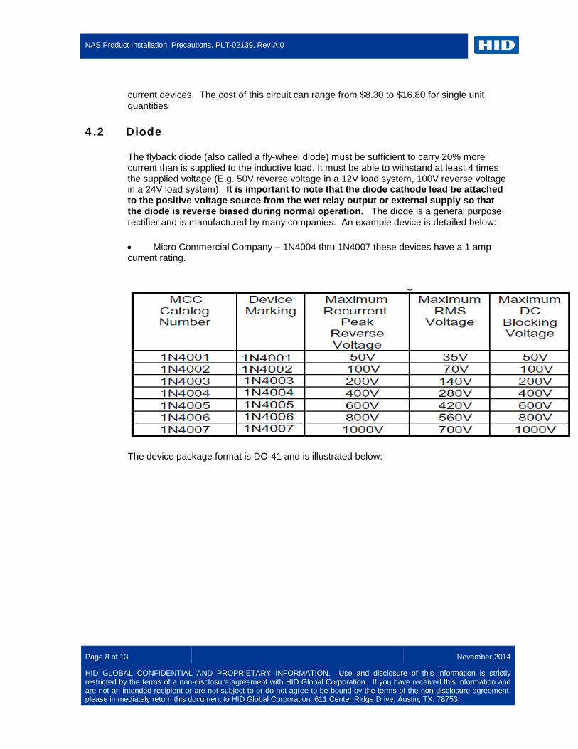
The flyback diode (also called a fly-wheel diode) must be sufficient to carry 20% more current than is supplied to the inductive load. It must be able to withstand at least 4 times the supplied voltage (E.g. 50V reverse voltage in a 12V load system, 100V reverse voltage in a 24V load system). It is important to note that the diode cathode lead be attached to the positive voltage source from the wet relay output or external supply so that the diode is reverse biased during normal operation. The diode is a general purpose rectifier and is manufactured by many companies. An example device is detailed below:
• Micro Commercial Company – 1N4004 thru 1N4007 these devices have a 1 amp current rating.
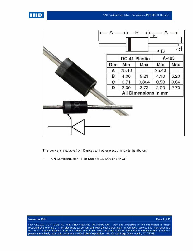
The device package format is DO-41 and is illustrated below:
NAS Product Installation Precautions, PLT-02139, Rev A.0
November 2014 Page 9 of 13
HID GLOBAL CONFIDENTIAL AND PROPRIETARY INFORMATION. Use and disclosure of this information is strictly restricted by the terms of a non-disclosure agreement with HID Global Corporation. If you have received this information and are not an intended recipient or are not subject to or do not agree to be bound by the terms of the non-disclosure agreement, please immediately return this document to HID Global Corporation, , 611 Center Ridge Drive, Austin, TX. 78753.
This device is available from DigiKey and other electronic parts distributors.
• ON Semiconductor – Part Number 1N4936 or 1N4937

NAS Product Installation Precautions, PLT-02139, Rev A.0
Page 10 of 13 November 2014
HID GLOBAL CONFIDENTIAL AND PROPRIETARY INFORMATION. Use and disclosure of this information is strictly restricted by the terms of a non-disclosure agreement with HID Global Corporation. If you have received this information and are not an intended recipient or are not subject to or do not agree to be bound by the terms of the non-disclosure agreement, please immediately return this document to HID Global Corporation, 611 Center Ridge Drive, Austin, TX. 78753.
The diode provides a more economical solution. The cost of diodes ranges from $0.20 to $1.00 in single unit quantities.
5 Dry Mode Configuration
The HID line of NAS products can be configured to use the internal contacts of the relays in a mode isolated from the internal circuitry of the product. This is referred to as operating in “Dry” mode. In this mode the relay contacts provide a switch for higher current loads provided by an external power supply. This is normally recommended for magnetic locks as the magnetic coils require additional current to operate properly; current requirements can vary widely between different manufacturers products and may have a significant impact upon the installation design and reliability. When operating in Dry mode, for high current inductive loads it is recommended that at least a resistive capacitive snubber circuit is placed across the contacts of the relay.
NCCOMNONC
COMNO
P10AUX
DS
Relay Coil
+DC Power Supply
(12 – 24 Volt)
-
EH400
As illustrated below

NAS Product Installation Precautions, PLT-02139, Rev A.0
November 2014 Page 11 of 13
HID GLOBAL CONFIDENTIAL AND PROPRIETARY INFORMATION. Use and disclosure of this information is strictly restricted by the terms of a non-disclosure agreement with HID Global Corporation. If you have received this information and are not an intended recipient or are not subject to or do not agree to be bound by the terms of the non-disclosure agreement, please immediately return this document to HID Global Corporation, , 611 Center Ridge Drive, Austin, TX. 78753.
NCCOMNONC
COMNO
P10AUX
DS
Relay Coil
+DC Power Supply
(12 – 24 Volt)
-
EH400 Snubber Circuit
Some loads may have a flyback diode built into them, but this is not universally true. If no diode is fitted to the load, then best practice would dictate that an external flyback diode be fitted at the load.
NCCOMNONC
COMNO
P10AUX
DS
Relay Coil
+DC Power Supply
(12 – 24 Volt)
-
EH400 Snubber Circuit
Note the cathode terminal of the diode is connected to the positive potential (+) side of the relay.
6 Wet Mode Configuration
Wet mode provides a source of power from the HID line of NAS products at voltages ranging between 12 and 24 volts through the contacts to an attached device. The current supplied is dependent on the voltage being supported as well as the source of the power. As indicated in the above discussion, large inductive loads can inject negative spikes into the power supply. This can affect the operation of the product or otherwise cause interference to unconnected systems. The relay parts used in the HID line of NAS products for operation of the door switch and auxiliary switch support a maximum of 2 Amps DC at 30V; Note – the total wet mode current rating of the product depends on multiple factors as outlined in the installation manual for the product and is not a simple ‘number of relays x 2 Amps’ calculation.
The following connection diagram indicates an unprotected configuration,
NAS Product Installation Precautions, PLT-02139, Rev A.0
Page 12 of 13 November 2014
HID GLOBAL CONFIDENTIAL AND PROPRIETARY INFORMATION. Use and disclosure of this information is strictly restricted by the terms of a non-disclosure agreement with HID Global Corporation. If you have received this information and are not an intended recipient or are not subject to or do not agree to be bound by the terms of the non-disclosure agreement, please immediately return this document to HID Global Corporation, 611 Center Ridge Drive, Austin, TX. 78753.
EH400
NCCOMNONC
COMNO
P10AUX
DS
DC(12-24) Volts
Relay Coil
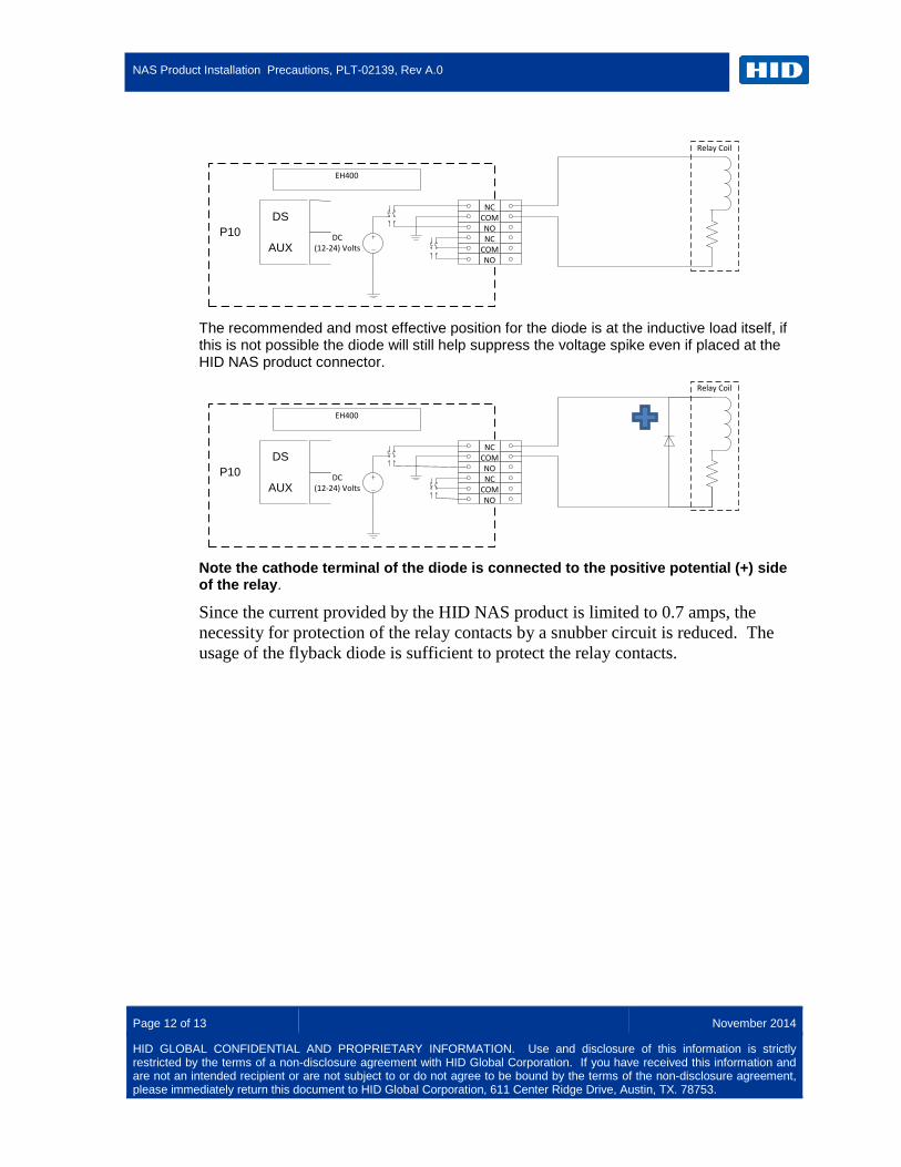
The recommended and most effective position for the diode is at the inductive load itself, if this is not possible the diode will still help suppress the voltage spike even if placed at the HID NAS product connector.
EH400
NCCOMNONC
COMNO
P10AUX
DS
DC(12-24) Volts
Relay Coil
Note the cathode terminal of the diode is connected to the positive potential (+) side of the relay.
Since the current provided by the HID NAS product is limited to 0.7 amps, the necessity for protection of the relay contacts by a snubber circuit is reduced. The usage of the flyback diode is sufficient to protect the relay contacts.

NAS Product Installation Precautions, PLT-02139, Rev A.0
November 2014 Page 13 of 13
HID GLOBAL CONFIDENTIAL AND PROPRIETARY INFORMATION. Use and disclosure of this information is strictly restricted by the terms of a non-disclosure agreement with HID Global Corporation. If you have received this information and are not an intended recipient or are not subject to or do not agree to be bound by the terms of the non-disclosure agreement, please immediately return this document to HID Global Corporation, , 611 Center Ridge Drive, Austin, TX. 78753.
HID Global Headquarters:
North America: +1 949 732 2000
Toll Free: 1 800 237 7769 Europe, Middle East, Africa: +49 6123 791 0
Asia Pacific: +852 3160 9800
Latin America: +52 477 779 1492
support.hidglobal.com
h i d g l o b a l . c o m