Embed Size (px)
Citation preview


Faci
lity
Nam
eP
oet B
iore
finin
g - L
eips
icD
G T
ype
Turb
ine
Faci
lity
Loca
tion
Leip
sic,
OH
Dat
e10
/11/
2016
Tota
l Gen
erat
ion
3500
KW
Line
IEE
E 1
547.
1 ID
IEE
E 1
547.
1 Te
st
Type / Production
Test
Field Test per 1547.1
Not Applicable
Com
plia
nce
Dev
ice
(Equ
ipm
ent u
nder
Tes
t, E
UT)
Ref
eren
ced
Doc
umen
t(s)
Not
es
15.
1.2.
1O
pera
tiona
l Tem
pera
ture
XS
EL7
00G
+ R
elay
700G
_DS
_201
6033
4P
age
302
5.1.
2.2
Sto
rage
Tem
pera
ture
XS
EL7
00G
+ R
elay
700G
_DS
_201
6033
4P
age
303
5.2.
1.2
Ove
rvol
tage
- M
agni
tude
XX
SE
L700
G+
Rel
ayA
dden
dum
test
pro
ceed
ure
Pag
e 31
45.
2.1.
3O
verv
olta
ge -
Trip
Tim
eX
XS
EL7
00G
+ R
elay
Add
endu
m te
st p
roce
edur
eP
age
315
5.2.
2.2
Und
ervo
ltage
- M
agni
tude
XX
SE
L700
G+
Rel
ayA
dden
dum
test
pro
ceed
ure
Pag
e 31
65.
2.2.
3U
nder
volta
ge -
Trip
Tim
eX
XS
EL7
00G
+ R
elay
Add
endu
m te
st p
roce
edur
eP
age
317
5.3.
1.2
Ove
rfreq
uenc
y - M
agni
tude
XS
EL7
00G
+ R
elay
700G
_DS
_201
6033
4P
age
328
5.3.
1.3
Ove
rfreq
uenc
y - T
rip T
ime
XS
EL7
00G
+ R
elay
700G
_DS
_201
6033
4P
age
329
5.3.
2.2
Und
erfre
quen
cy -
Mag
nitu
deX
SE
L700
G+
Rel
ay70
0G_D
S_2
0160
334
Pag
e 32
105.
3.2.
3U
nder
frequ
ency
- Tr
ip T
ime
XS
EL7
00G
+ R
elay
700G
_DS
_201
6033
4P
age
3211
5.4.
1.2
Syn
chro
niza
tion
- Met
hod
1 - V
aria
tion
1X
SE
L700
G+
Rel
ay70
0G_D
S_2
0160
334
Pag
e 34
125.
4.2.
2S
ynch
roni
zatio
n - M
etho
d 1
- Var
iatio
n 2
XS
EL7
00G
+ R
elay
700G
_DS
_201
6033
4P
age
3413
5.4.
3.2
Syn
chro
niza
tion
- Met
hod
1 - V
aria
tion
3X
SE
L700
G+
Rel
ay70
0G_D
S_2
0160
334
Pag
e 34
145.
4.4.
2S
tartu
p C
urre
nt -
Met
hod
2X
155.
5.1.
2P
rote
ctio
n fro
m E
lect
rom
agne
tic In
terfe
renc
eX
SE
L700
G+
Rel
ay70
0G_D
S_2
0160
334
Pag
e 30
165.
5.2.
2S
urge
with
stan
d P
erfo
rman
ceX
SE
L700
G+
Rel
ay70
0G_D
S_2
0160
334
Pag
e 30
175.
5.3.
2D
iele
ctric
Tes
t of P
aral
lelin
g D
evic
eX
SE
L700
G+
Rel
ayA
dden
dum
test
pro
ceed
ure
185.
6.2
Lim
itatio
n of
DC
Inje
ctio
n (In
verte
rs w
ithou
t XFM
R)
X19
5.7.
1.2
Uni
nten
tiona
l Isl
andi
ng T
est
XS
EL7
00G
+ R
elay
Add
endu
m te
st p
roce
edur
e20
5.7.
2.2
Uni
nten
tiona
l Isl
andi
ng T
est f
or S
ynch
rono
us G
ener
ator
s
XS
EL7
00G
+ R
elay
Add
endu
m te
st p
roce
edur
e21
5.8.
1.2
Rev
erse
-Pow
er (f
or u
nint
entio
nal i
slan
ding
)X
SE
L700
G+
Rel
ay70
0G_D
S_2
0160
334
Pag
e 32
225.
8.2.
2R
ever
se-P
ower
Tim
e Te
stS
EL7
00G
+ R
elay
700G
_DS
_201
6033
4P
age
3223
5.9.
2O
pen
Pha
se
XS
EL7
00G
+ R
elay
Add
endu
m te
st p
roce
edur
e24
5.10
.2R
econ
nect
Fol
low
ing
Abn
orm
al C
ondi
tion
Dis
conn
ect
XS
EL7
00G
+ R
elay
Add
endu
m te
st p
roce
edur
e25
5.11
.1.1
Har
mon
ics
XS
EL7
00G
+ R
elay
Add
endu
m te
st p
roce
edur
e26
5.11
.2.1
Har
mon
ics
for S
ynch
rono
us G
ener
ator
sX
SE
L700
G+
Rel
ayA
dden
dum
test
pro
ceed
ure
275.
11.3
.1H
arm
onic
s fo
r Ind
uctio
n G
ener
ator
sX
286.
1.2
Res
pons
e to
Abn
orm
al V
olta
geX
SE
L700
G+
Rel
ayA
dden
dum
test
pro
ceed
ure
296.
2.2
Res
pons
e to
Abn
orm
al F
requ
ency
XS
EL7
00G
+ R
elay
Add
endu
m te
st p
roce
edur
e30
6.3.
1.1
Syn
chro
niza
tion
Pro
duct
ion
XS
EL7
00G
+ R
elay
Add
endu
m te
st p
roce
edur
e31
6.3.
2.1
Opt
iona
l Tes
t for
Equ
ipm
ent w
ith S
ynch
roni
zing
Dis
able
X32
7.2
Ver
ifica
tions
and
Insp
ectio
nsX
337.
4.1
Rev
erse
-Pow
er o
r Min
imum
Pow
er T
est
XS
EL7
00G
+ R
elay
Add
endu
m te
st p
roce
edur
e34
7.4.
2N
on-Is
land
ing
Func
tiona
lity
Test
XS
EL7
00G
+ R
elay
Add
endu
m te
st p
roce
edur
e35
7.4.
3O
ther
Uni
nten
tiona
l Isl
andi
ng T
est
X36
7.5.
1C
ease
-to-E
nerg
ize
Func
tiona
lity
XS
EL7
00G
+ R
elay
Add
endu
m te
st p
roce
edur
e
DIS
TRIB
UTE
D G
ENER
ATI
ON
IEEE
154
7.1
TEST
ING
MA
TRIX
Atta
chm
ent 1
0

SEL-700G Data Sheet Schweitzer Engineering Laboratories, Inc.
30
Port 2 Serial
Wavelength: 820 nm
Optical Connector Type: ST
Fiber Type: Multimode
Link Budget: 8 dB
Typical TX Power: –16 dBm
RX Min. Sensitivity: –24 dBm
Fiber Size: 62.5/125 µm
Approximate Range: ~1 km
Data Rate: 5 Mb
Typical Fiber Attenuation: –4 dB/km
Optional Communications CardsOption 1: EIA-232 or EIA-485 communications
card
Option 2: DeviceNet communications card
Communications ProtocolsSEL, Modbus, DNP, FTP, TCP/IP, Telnet, SNTP, IEC 61850,
MIRRORED BITS, EVMSG, C37.118 (synchrophasors), and DeviceNet.
Operating TemperatureIEC Performance Rating: –40 to +85C (–40 to +185F)
(per IEC/EN 60068-2-1 and 60068-2-2)
NOTE: Not applicable to UL applicationsNOTE: LCD contrast is impaired for temperatures below –20°C and
above +70°C
DeviceNet Communications Card Rating: +60°C (140°F) maximum
Operating EnvironmentPollution Degree: 2
Overvoltage Category: II
Atmospheric Pressure: 80–110 kPa
Relative Humidity: 5–95%, noncondensing
Maximum Altitude: 2000 m
Dimensions144.0 mm (5.67 in.) x 192.0 mm (7.56 in.) x 147.4 mm (5.80 in.)
Weight2.0 kg (4.4 lbs)
Relay Mounting Screw (#8–32) Tightening TorqueMinimum: 1.4 Nm (12 in-lb)
Maximum: 1.7 Nm (15 in-lb)
Terminal Connections
Terminal Block
Screw Size: #6
Ring Terminal Width: 0.310 inch maximum
Terminal Block Tightening Torque
Minimum: 0.9 Nm (8 in-lb)
Maximum: 1.4 Nm (12 in-lb)
Compression Plug Tightening Torque
Minimum: 0.5 Nm (4.4 in-lb)
Maximum: 1.0 Nm (8.8 in-lb)
Compression Plug Mounting Ear Screw Tightening Torque
Minimum: 0.18 Nm (1.6 in-lb)
Maximum: 0.25 Nm (2.2 in-lb)
Type Tests
Environmental TestsEnclosure Protection: IEC 60529:2001
IP65 enclosed in panelIP20 for terminalsIP54 rated terminal dust protection
assembly (SEL Part #915900170). 10°C temperature derating applies to the temperature specifications of the relay.
Vibration Resistance: IEC 60255-21-1:1988, Class 2 EnduranceClass 2 Response
IEC 60255-21-3:1993, Class 2
Shock Resistance: IEC 60255-21-2:1988, Class 1 Shock Withstand, BumpClass 2 Shock Response
Cold: IEC 60068-2-1:2007–40°C, 16 hours
Damp Heat, Steady State: IEC 60068-2-78:200140°C, 93% relative humidity, 4 days
Damp Heat, Cyclic: IEC 60068-2-30:200525–55°C, 6 cycles, 95% relative humidity
Dry Heat: IEC 60068-2-2:200785°C, 16 hours
Dielectric Strength and Impulse TestsDielectric (HiPot): IEC 60255-5:2000
IEEE C37.90-20052.5 kVac on current inputs, voltage
inputs, contact I/O2.0 kVac on analog inputs1.0 kVac on analog output2.83 kVdc on power supply
Impulse: IEC 60255-5:20000.5 J, 4.7 kV on power supply,
contact I/O, ac current and voltage inputs
0.5 J, 530 V on analog outputs
RFI and Interference Tests
EMC Immunity
Electrostatic Discharge Immunity:
IEC 60255-22-2:2008IEC 61000-4-2:2008
Severity Level 48 kV contact discharge15 kV air discharge
Radiated RF Immunity: IEC 60255-22-3:2007IEC 61000-4-3:2002, 10 V/mIEEE C37.90.2-1995, 35 V/m
Fast Transient, Burst Immunity:
IEC 60255-22-4:2008IEC 61000-4-4:2004
4 kV @ 2.5 kHz2 kV @ 5.0 kHz for comm. ports
Surge Immunity: IEC 60255-22-5:2008IEC 61000-4-5:2005
2 kV line-to-line4 kV line-to-earth
Surge Withstand Capability Immunity:
IEC 60255-22-1:19882.5 kV common mode1.0 kV differential mode1 kV common mode on comm. ports
IEEE C37.90.1-20022.5 kV oscillatory4 kV fast transient
Conducted RF Immunity: IEC 60255-22-6:2001IEC 61000-4-6:2006, 10 Vrms
Magnetic Field Immunity: IEC 61000-4-8:20011000 A/m for 3 seconds100 A/m for 1 minute
Schweitzer Engineering Laboratories, Inc. SEL-700G Data Sheet
31
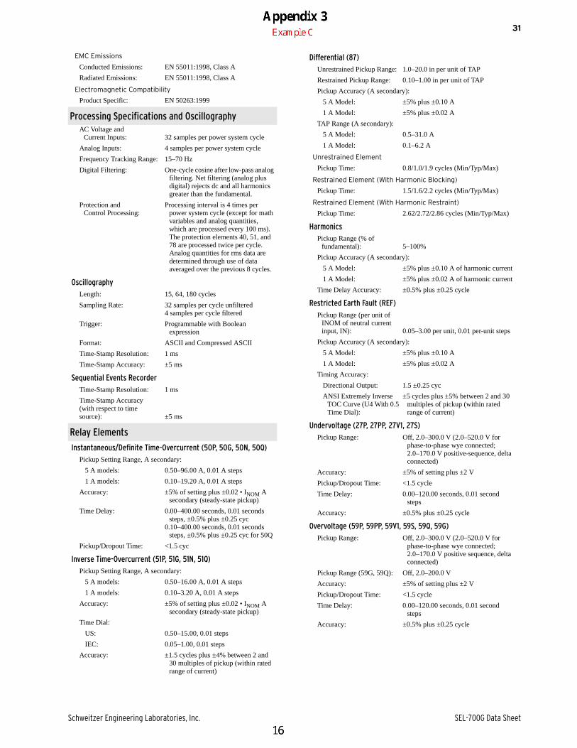
EMC Emissions
Conducted Emissions: EN 55011:1998, Class A
Radiated Emissions: EN 55011:1998, Class A
Electromagnetic Compatibility
Product Specific: EN 50263:1999
Processing Specifications and OscillographyAC Voltage and
Current Inputs: 32 samples per power system cycle
Analog Inputs: 4 samples per power system cycle
Frequency Tracking Range: 15–70 Hz
Digital Filtering: One-cycle cosine after low-pass analog filtering. Net filtering (analog plus digital) rejects dc and all harmonics greater than the fundamental.
Protection and Control Processing:
Processing interval is 4 times per power system cycle (except for math variables and analog quantities, which are processed every 100 ms). The protection elements 40, 51, and 78 are processed twice per cycle. Analog quantities for rms data are determined through use of data averaged over the previous 8 cycles.
OscillographyLength: 15, 64, 180 cycles
Sampling Rate: 32 samples per cycle unfiltered4 samples per cycle filtered
Trigger: Programmable with Boolean expression
Format: ASCII and Compressed ASCII
Time-Stamp Resolution: 1 ms
Time-Stamp Accuracy: ±5 ms
Sequential Events RecorderTime-Stamp Resolution: 1 ms
Time-Stamp Accuracy(with respect to timesource): ±5 ms
Relay Elements
Instantaneous/Definite Time-Overcurrent (50P, 50G, 50N, 50Q)Pickup Setting Range, A secondary:
5 A models: 0.50–96.00 A, 0.01 A steps
1 A models: 0.10–19.20 A, 0.01 A steps
Accuracy: ±5% of setting plus ±0.02 • INOM A secondary (steady-state pickup)
Time Delay: 0.00–400.00 seconds, 0.01 seconds steps, ±0.5% plus ±0.25 cyc
0.10–400.00 seconds, 0.01 seconds steps, ±0.5% plus ±0.25 cyc for 50Q
Pickup/Dropout Time: <1.5 cyc
Inverse Time-Overcurrent (51P, 51G, 51N, 51Q)Pickup Setting Range, A secondary:
5 A models: 0.50–16.00 A, 0.01 A steps
1 A models: 0.10–3.20 A, 0.01 A steps
Accuracy: ±5% of setting plus ±0.02 • INOM A secondary (steady-state pickup)
Time Dial:
US: 0.50–15.00, 0.01 steps
IEC: 0.05–1.00, 0.01 steps
Accuracy: ±1.5 cycles plus ±4% between 2 and 30 multiples of pickup (within rated range of current)
Differential (87)Unrestrained Pickup Range: 1.0–20.0 in per unit of TAP
Restrained Pickup Range: 0.10–1.00 in per unit of TAP
Pickup Accuracy (A secondary):
5 A Model: ±5% plus ±0.10 A
1 A Model: ±5% plus ±0.02 A
TAP Range (A secondary):
5 A Model: 0.5–31.0 A
1 A Model: 0.1–6.2 A
Unrestrained Element
Pickup Time: 0.8/1.0/1.9 cycles (Min/Typ/Max)
Restrained Element (With Harmonic Blocking)
Pickup Time: 1.5/1.6/2.2 cycles (Min/Typ/Max)
Restrained Element (With Harmonic Restraint)
Pickup Time: 2.62/2.72/2.86 cycles (Min/Typ/Max)
HarmonicsPickup Range (% of
fundamental): 5–100%
Pickup Accuracy (A secondary):
5 A Model: ±5% plus ±0.10 A of harmonic current
1 A Model: ±5% plus ±0.02 A of harmonic current
Time Delay Accuracy: ±0.5% plus ±0.25 cycle
Restricted Earth Fault (REF)Pickup Range (per unit of
INOM of neutral current input, IN): 0.05–3.00 per unit, 0.01 per-unit steps
Pickup Accuracy (A secondary):
5 A Model: ±5% plus ±0.10 A
1 A Model: ±5% plus ±0.02 A
Timing Accuracy:
Directional Output: 1.5 ±0.25 cyc
ANSI Extremely Inverse TOC Curve (U4 With 0.5 Time Dial):
±5 cycles plus ±5% between 2 and 30 multiples of pickup (within rated range of current)
Undervoltage (27P, 27PP, 27V1, 27S)Pickup Range: Off, 2.0–300.0 V (2.0–520.0 V for
phase-to-phase wye connected; 2.0–170.0 V positive-sequence, delta connected)
Accuracy: ±5% of setting plus ±2 V
Pickup/Dropout Time: <1.5 cycle
Time Delay: 0.00–120.00 seconds, 0.01 second steps
Accuracy: ±0.5% plus ±0.25 cycle
Overvoltage (59P, 59PP, 59V1, 59S, 59Q, 59G)Pickup Range: Off, 2.0–300.0 V (2.0–520.0 V for
phase-to-phase wye connected; 2.0–170.0 V positive sequence, delta connected)
Pickup Range (59G, 59Q): Off, 2.0–200.0 V
Accuracy: ±5% of setting plus ±2 V
Pickup/Dropout Time: <1.5 cycle
Time Delay: 0.00–120.00 seconds, 0.01 second steps
Accuracy: ±0.5% plus ±0.25 cycle

SEL-700G Data Sheet Schweitzer Engineering Laboratories, Inc.
32
Volts/Hertz (24)
Definite-Time Element
Pickup Range: 100–200%
Steady-State Pickup Accuracy: ±1% of setpoint
Pickup Time: 25 ms @ 60 Hz (Max)
Time-Delay Range: 0.04–400.00 s
Time-Delay Accuracy: ±0.1% plus ±4.2 ms @ 60 Hz
Reset Time Range: 0.00–400.00 s
Inverse-Time Element
Pickup Range: 100–200%
Steady-State Pickup Accuracy: ±1% of setpoint
Pickup Time: 25 ms @ 60 Hz (Max)
Curve: 0.5, 1.0, or 2.0
Factor: 0.1–10.0 s
Timing Accuracy: ±4% plus ±25 ms @ 60 Hz, for V/Hz above 1.2 multiple of pickup setting, and for operating times >4 s
Reset Time Range: 0.00–400.00 s
Composite-Time Element
Combination of Definite-Time and Inverse-Time specifications
User-Definable Curve Element
Pickup Range: 100–200%
Steady-State Pickup Accuracy: ±1% of setpoint
Pickup Time: 25 ms @ 60 Hz (Max)
Reset Time Range: 0.00–400.00 s
Directional Power (32)
Instantaneous/Definite Time, 3 Phase Elements
Type: +W, –W, +VAR, –VAR
Pickup Settings Range, VA secondary:
5 A Model: 1.0–6500.0 VA, 0.1 VA steps
1 A Model: 0.2–1300.0 VA, 0.1 VA steps
Accuracy: ±0.10 A • (L-L voltage secondary) and ±5% of setting at unity power factor for power elements and zero power factor for reactive power element (5 A nominal)
±0.02 A • (L-L voltage secondary) and ±5% of setting at unity power factor for power elements and zero power factor for reactive power element (1 A nominal)
Pickup/Dropout Time: <10 cycles
Time Delay: 0.00–240.00 seconds, 0.01 second steps
Accuracy: ±0.5% plus ±0.25 cycle
Frequency (81)Setting Range: Off, 15.0–70.0 Hz
Accuracy: ±0.01 Hz (V1 > 60 V) Pickup/Dropout Time: <4 cycles
Time Delay: 0.00–240.00 seconds, 0.01 second steps
Accuracy: ±0.5% plus ±0.25 cycle
RTD ProtectionSetting Range: Off, 1–250°C
Accuracy: ±2C
RTD Open-Circuit Detection: >250°C
RTD Short-Circuit Detection: <–50°C
RTD Types: PT100, NI100, NI120, CU10
RTD Lead Resistance: 25 ohm max. per lead
Update Rate: <3 s
Noise Immunity on RTD Inputs:
To 1.4 Vac (peak) at 50 Hz or greater frequency
RTD Trip/Alarm Time Delay: Approx. 6 s
Distance Element (21)Two zones of Compensator Distance elements with Load
Encroachment block
Reach Pickup Range: 5 A model: 0.1–100.0 ohms1 A model: 0.5–500.0 ohms
Offset Range: 5 A model: 0.0–10.0 ohms1 A model: 0.0–50.0 ohms
Steady-State Impedance Accuracy:
5 A model: ±5% plus ±0.1 ohm1 A mode: ±5% plus ±0.5 ohm
Pickup Time: 33 ms at 60 Hz (Max)
Definite-Time Delay: 0.00–400.00 s
Accuracy: ±0.1% plus ±0.25 cycle
Minimum Phase Current: 5 A model: 0.5 A1 A model: 0.1 A
Maximum Torque Angle Range: 90–45°, 1° step
Loss-of-Field Element (40)
Two Mho Zones
Zone 1 Offset: 5 A model: –50.0 to 0.0 ohms1 A model: –250.0 to 0.0 ohms
Zone 2 Offset: 5 A model: –50.0 to 50.0 ohms1 A model: –250.0 to 250.0 ohms
Zone 1 and Zone 2 Diameter: 5 A model: 0.1–100.0 ohms1 A model: 0.5–500.0 ohms
Steady-State Impedance Accuracy:
5 A model: ± 0.1 ohm plus±5% of (offset + diameter)
1 A model: ±0.5 ohm plus±5% of (offset + diameter)
Minimum Pos.-Seq. Signals: 5 A model: 0.25 V (V1), 0.25 A (I1)1 A model: 0.25 V (V1), 0.05 A (I1)
Directional Element Angle: –20.0° to 0.0°
Pickup Time: 3 cycles (Max)
Zone 1 and Zone 2 Definite-Time Delays: 0.00–400.00 s
Accuracy: ±0.1% plus ± ½ cycle
Voltage-Restrained Phase Time-Overcurrent Element (51V)Phase Pickup (A secondary): 5 A Model: 2.0–16.0 A
1 A Model: 0.4–3.2 A
Steady-State Pickup Accuracy:
5 A Model: ±5% plus ±0.10 A1 A Model: ±5% plus ±0.02 A
Time Dials: US: 0.50–15.00, 0.01 stepsIEC: 0.05–1.00, 0.01 steps
Accuracy: ±4% plus ±1.5 cycles for current between 2 and 20 multiples of pickup (within rated range of current)
Linear Voltage Restraint Range: 0.125–1.000 per unit of VNOM

Schweitzer Engineering Laboratories, Inc. SEL-700G Data Sheet
33
Voltage-Controlled Phase Time-Overcurrent Element (51C)Phase Pickup (A secondary): 5 A Model: 0.5–16.0 A
1 A Model: 0.1–3.2 A
Steady State Pickup Accuracy:
5 A Model: ±5% plus ±0.10 A1 A Model: ±5% plus ±0.02 A
Time Dials: US: 0.50–15.00, 0.01 stepsIEC: 0.05–1.00, 0.01 steps
Accuracy: ±4% plus ±1.5 cycles for current between 2 and 20 multiples of pickup (within rated range of current)
100 Percent Stator Ground Protection (64G)Neutral Fundamental
Overvoltage (64G1): OFF, 0.1–150.0 V
Steady-State Pickup Accuracy: ±5% plus ±0.1 V
Pickup Time: 1.5 cycles (Max)
Definite-Time Delay: 0.00–400.00 s
Accuracy: ±0.1% plus ±0.25 cycle
Third-Harmonic Voltage Differential or Third-Harmonic Neutral Undervoltage Pickup 64G2: 0.1–20.0 V
Steady-State Pickup Accuracy: ±5% plus ±0.1 V
Third-Harmonic VoltageDifferential Ratio Setting
Range: 0.0 to 5.0
Pickup Time: 3 cycles (Max)
Definite-Time Delay: 0.00–400.00 s
Accuracy: ±0.1% plus ±0.25 cycle
Field Ground Protection (64F) (Requires SEL-2664 Field Ground Module)
Field Ground Protection Element: 0.5–200.0 kilohms, 0.1 kilohm step
Pickup Accuracy: ±5% plus ±500 ohms for 48 ± VF ± 825 Vdc
±5% plus ±20 kilohms for 825 < VF ± 1500 Vdc
(VF is the generator field winding excitation dc voltage)
Pickup Time: 2 s if the injection frequency in the SEL-2664 is selected at 1 Hz
8 s if the injection frequency in the SEL-2664 is selected at 0.25 Hz
Definite-Time Delay: 0.0–99.0 s
Maximum Definite-Time Delay Accuracy: ±0.5% plus ±5 ms
Out-of-Step Element (78)Forward Reach: 5 A model: 0.1–100.0 ohms
1 A model: 0.5–500.0 ohms
Reverse Reach: 5 A model: 0.1–100.0 ohms1 A model: 0.5–500.0 ohms
Single Blinder
Right Blinder: 5 A model: 0.1–50.0 ohms1 A model: 0.5–250.0 ohms
Left Blinder: 5 A model: 0.1–50.0 ohms1 A model: 0.5–250.0 ohms
Double Blinder
Outer Resistance Blinder: 5 A model: 0.2–100.0 ohms1 A model: 1.0–500.0 ohms
Inner Resistance Blinder: 5 A model: 0.1–50.0 ohms1 A model: 0.5–250.0 ohms
Steady-State Impedance Accuracy:
5 A model: ±0.1 ohm plus ±5% of diameter
1 A model: ±0.5 ohm plus ±5% of diameter
Pos.-Seq. Current Supervision:
5 A model: 0.25–30.00 A1 A model: 0.05–6.00 A
Pickup Time: 3 cycles (Max)
Definite Time Delay: 0.00–1.00 s, 0.01 s step
Trip Delay Range: 0.00–1.00 s, 0.01 s step
Trip Duration Range: 0.00–5.00 s, 0.01 s step
Definite-Time Timers: ±0.1% plus ±½ cycle
Ground Differential Elements (87N)Ground Differential Pickup: 5 A Model:
0.10*CTR/CTRN – 15.00 A
1 A Model: 0.02*CTR/CTRN – 3.00 A
(Ratio CTR/CTRN must be within 1.0–40.0)
Steady-State Pickup Accuracy:
5 A Model: ±5% plus ±0.10 A1 A Model: ±5% plus ±0.02 A
Pickup Time: 1.5 cycles (Max)
Time Delay Range: 0.00–5.00 s
Time Delay Accuracy: ±0.5% plus ±¼ cycle
Negative-Sequence Overcurrent Elements (46)Definite-Time and Inverse-
Time Neg.-Seq. I2 Pickup:2%–100% of generator rated
secondary current
Generator Rated Secondary Current:
5 A Model: 1.0–10.0 A secondary1 A Model: 0.2–2.0 A secondary
Steady-State Pickup Accuracy:
5 A Model: ±0.025 A plus ±3%1 A Model: ±0.005 A plus ±3%
Pickup Time: 50 ms at 60 Hz (max)
Definite-Time Delay Setting Range: 0.02–999.90 s
Maximum Definite-Time Delay Accuracy: ±0.1% plus ±4.2 ms at 60 Hz
Inverse-Time Element Time Dial: K = 1 to 100 s
Linear Reset Time: 240 s fixed
Inverse-Time Timing Accuracy:
±4% plus ±50 ms at 60 Hz for | I2 | above 1.05 multiples of pickup
Rate-of-Change of Frequency (81R)Pickup Setting Range: Off, 0.10–15.00 Hz/s
Accuracy: ±100 mHz/s plus ±3.33% of pickup
Trend Setting: INC, DEC, ABS
Pickup/Dropout Time: 3–30 cycles, depending on pickup setting
Pickup/ Dropout Delay Range:
0.10–60.00/0.00–60.00 s, 01 s increments
Voltage Supervision (Positive Sequence) Pickup Range: Off, 12.5–300.0 V, 0.1 V increments
SEL-700G Data Sheet Schweitzer Engineering Laboratories, Inc.
34
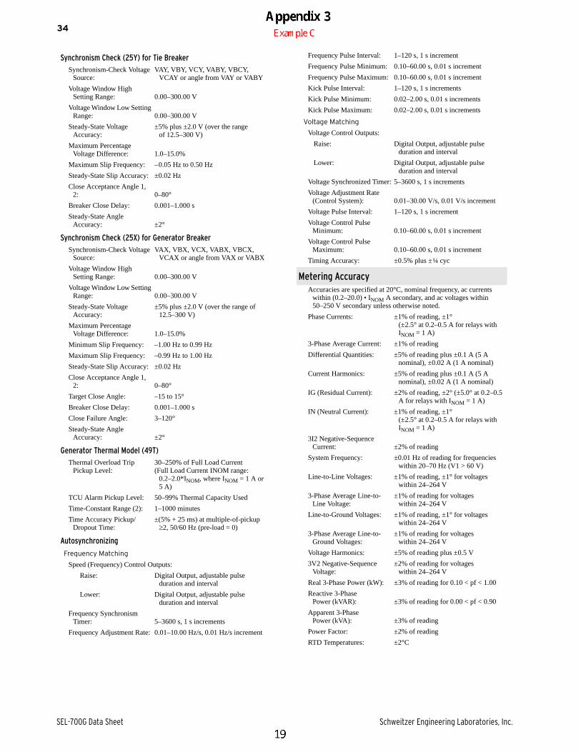
Synchronism Check (25Y) for Tie BreakerSynchronism-Check Voltage
Source:VAY, VBY, VCY, VABY, VBCY,
VCAY or angle from VAY or VABY
Voltage Window High Setting Range: 0.00–300.00 V
Voltage Window Low Setting Range: 0.00–300.00 V
Steady-State Voltage Accuracy:
±5% plus ±2.0 V (over the range of 12.5–300 V)
Maximum Percentage Voltage Difference: 1.0–15.0%
Maximum Slip Frequency: –0.05 Hz to 0.50 Hz
Steady-State Slip Accuracy: ±0.02 Hz
Close Acceptance Angle 1, 2: 0–80°
Breaker Close Delay: 0.001–1.000 s
Steady-State Angle Accuracy: ±2°
Synchronism Check (25X) for Generator BreakerSynchronism-Check Voltage
Source:VAX, VBX, VCX, VABX, VBCX,
VCAX or angle from VAX or VABX
Voltage Window High Setting Range: 0.00–300.00 V
Voltage Window Low Setting Range: 0.00–300.00 V
Steady-State Voltage Accuracy:
±5% plus ±2.0 V (over the range of 12.5–300 V)
Maximum Percentage Voltage Difference: 1.0–15.0%
Minimum Slip Frequency: –1.00 Hz to 0.99 Hz
Maximum Slip Frequency: –0.99 Hz to 1.00 Hz
Steady-State Slip Accuracy: ±0.02 Hz
Close Acceptance Angle 1, 2: 0–80°
Target Close Angle: –15 to 15°
Breaker Close Delay: 0.001–1.000 s
Close Failure Angle: 3–120°
Steady-State Angle Accuracy: ±2°
Generator Thermal Model (49T)Thermal Overload Trip
Pickup Level:30–250% of Full Load Current(Full Load Current INOM range:
0.2–2.0*INOM, where INOM = 1 A or 5 A)
TCU Alarm Pickup Level: 50–99% Thermal Capacity Used
Time-Constant Range (2): 1–1000 minutes
Time Accuracy Pickup/Dropout Time:
±(5% + 25 ms) at multiple-of-pickup2, 50/60 Hz (pre-load = 0)
Autosynchronizing
Frequency Matching
Speed (Frequency) Control Outputs:
Raise: Digital Output, adjustable pulse duration and interval
Lower: Digital Output, adjustable pulse duration and interval
Frequency Synchronism Timer: 5–3600 s, 1 s increments
Frequency Adjustment Rate: 0.01–10.00 Hz/s, 0.01 Hz/s increment
Frequency Pulse Interval: 1–120 s, 1 s increment
Frequency Pulse Minimum: 0.10–60.00 s, 0.01 s increment
Frequency Pulse Maximum: 0.10–60.00 s, 0.01 s increment
Kick Pulse Interval: 1–120 s, 1 s increments
Kick Pulse Minimum: 0.02–2.00 s, 0.01 s increments
Kick Pulse Maximum: 0.02–2.00 s, 0.01 s increments
Voltage Matching
Voltage Control Outputs:
Raise: Digital Output, adjustable pulse duration and interval
Lower: Digital Output, adjustable pulse duration and interval
Voltage Synchronized Timer: 5–3600 s, 1 s increments
Voltage Adjustment Rate (Control System): 0.01–30.00 V/s, 0.01 V/s increment
Voltage Pulse Interval: 1–120 s, 1 s increment
Voltage Control Pulse Minimum: 0.10–60.00 s, 0.01 s increment
Voltage Control Pulse Maximum: 0.10–60.00 s, 0.01 s increment
Timing Accuracy: ±0.5% plus ±¼ cyc
Metering AccuracyAccuracies are specified at 20°C, nominal frequency, ac currents
within (0.2–20.0) • INOM A secondary, and ac voltages within 50–250 V secondary unless otherwise noted.
Phase Currents: ±1% of reading, ±1° (±2.5° at 0.2–0.5 A for relays with INOM = 1 A)
3-Phase Average Current: ±1% of reading
Differential Quantities: ±5% of reading plus ±0.1 A (5 A nominal), ±0.02 A (1 A nominal)
Current Harmonics: ±5% of reading plus ±0.1 A (5 A nominal), ±0.02 A (1 A nominal)
IG (Residual Current): ±2% of reading, ±2° (±5.0° at 0.2–0.5 A for relays with INOM = 1 A)
IN (Neutral Current): ±1% of reading, ±1° (±2.5° at 0.2–0.5 A for relays with INOM = 1 A)
3I2 Negative-Sequence Current: ±2% of reading
System Frequency: ±0.01 Hz of reading for frequencies within 20–70 Hz (V1 > 60 V)
Line-to-Line Voltages: ±1% of reading, ±1° for voltages within 24–264 V
3-Phase Average Line-to-Line Voltage:
±1% of reading for voltages within 24–264 V
Line-to-Ground Voltages: ±1% of reading, ±1° for voltages within 24–264 V
3-Phase Average Line-to-Ground Voltages:
±1% of reading for voltages within 24–264 V
Voltage Harmonics: ±5% of reading plus ±0.5 V
3V2 Negative-Sequence Voltage:
±2% of reading for voltages within 24–264 V
Real 3-Phase Power (kW): ±3% of reading for 0.10 < pf < 1.00
Reactive 3-Phase Power (kVAR): ±3% of reading for 0.00 < pf < 0.90
Apparent 3-Phase Power (kVA): ±3% of reading
Power Factor: ±2% of reading
RTD Temperatures: ±2°C

Appendix 3
20
Example D
ID Document
A Brand XYZ, Model 123 Converter Test (IEC XXXXX-XX)
B Brand ABC, Model 456 Turbine Type Test – Design Evaluation
C Brand ABC, Model 456 Turbine Type Test – Annex to Design
D Brand XYZ, Model 123 Converter Test (UL XXXX)
E Brand DEF Relay Manufacturer Specification
F Brand DEF Relay Test Report
G Brand ABC Turbine Technical Specifications
H Previous Transformer Inrush Test Result
I Brand GHI Breaker Specifications
Line Testing Notes
1 All field tests shall be conducted per IEEE 1547.1 procedures in referenced section
2 General requirements contained in IEEE 1547.1, Section 4 apply to field tests
3 Field tests conducted on complete commissioned facility to Area EPS
4 All field test data recording and instrumentation shall be controlled by the testing entity
5 Facility technicians will operate facility for purpose of field tests
6 More notes
7 More notes
8 More notes
9 And more notes
10
11
12
Date:
DISTRIBUTED GENERATION IEEE 1547.1 TESTING DOCUMENTATION INDEX
Facility Name:
Facility Location:
Total Generation:
DG Type: