Embed Size (px)
Citation preview

Item No. 21100
Joint Standard
NACE No. 12/AWS C2.23M/SSPC-CS 23.00 Specification for the Application of Thermal Spray
Coatings (Metallizing) of Aluminum, Zinc, and Their Alloys and Composites for the Corrosion
Protection of Steel This NACE International (NACE)/American Welding Society (AWS)/SSPC: The Society for Protective Coatings standard represents a consensus of those individual members who have reviewed this document, its scope, and provisions. It is intended to aid the manufacturer, the consumer, and the general public. Its acceptance does not in any respect preclude anyone, whether he has adopted the standard or not, from manufacturing, marketing, purchasing, or using products, processes, or procedures not addressed in this standard. Nothing contained in this NACE/AWS/SSPC standard is to be construed as granting any right, by implication or otherwise, to manufacture, sell, or use in connection with any method, apparatus, or product covered by Letters Patent, or as indemnifying or protecting anyone against liability for infringement of Letters Patent. This standard represents current technology and should in no way be interpreted as a restriction on the use of better procedures or materials. Neither is this standard intended to apply in all cases relating to the subject. Unpredictable circumstances may negate the usefulness of this standard in specific instances. NACE, AWS, and SSPC assume no responsibility for the interpretation or use of this standard by other parties and accept responsibility for only those official interpretations issued by NACE, AWS, or SSPC in accordance with their governing procedures and policies which preclude the issuance of interpretations by individual volunteers. Users of this NACE/AWS/SSPC standard are responsible for reviewing appropriate health, safety, environmental, and regulatory documents and for determining their applicability in relation to this standard prior to its use. This NACE/AWS/SSPC standard may not necessarily address all potential health and safety problems or environmental hazards associated with the use of materials, equipment, and/or operations detailed or referred to within this standard. Users of this NACE/AWS/SSPC standard are also responsible for establishing appropriate health, safety, and environmental protection practices, in consultation with appropriate regulatory authorities if necessary, to achieve compliance with any existing applicable regulatory requirements prior to the use of this standard. CAUTIONARY NOTICE: NACE/AWS/SSPC standards are subject to periodic review, and may be revised or withdrawn at any time without prior notice. The user is cautioned to obtain the latest edition. NACE, AWS, and SSPC require that action be taken to reaffirm, revise, or withdraw this standard no later than five years from the date of initial publication.
Approved July 2003
ISBN 0-87171-713-1
©2003, NACE International, American Welding Society, and SSPC: The Society for Protective Coatings
An American National Standard Approved March 2003
NACE International
1440 South Creek Drive Houston, TX 77084-4906
(telephone +1 281/228-6200)
American Welding Society 550 NW LeJeune Road
Miami, FL 33126 (telephone +1 800-443-9353)
SSPC: The Society for Protective Coatings
40 24th Street, Sixth Floor Pittsburgh, PA 15222-4656
(telephone +1 412/281-2331)
Printed by NACE International
NACE No. 12/AWS C2.23M/SSPC-CS 23.00
NACE International i
________________________________________________________________________
Foreword
This “Specification for the Application of Thermal Spray Coatings (Metallizing) of Aluminum, Zinc, Their Alloys, and Composites for the Corrosion Protection of Steel” is issued to meet a critical industry and government need. Thermal spray coatings (TSCs) are used extensively for the corrosion protection of steel and iron in a wide range of environments. The corrosion tests carried out by the American Welding Society(1) and the marine-atmosphere performance reports of ASTM(2) and the LaQue Center for Corrosion Technology(3) confirm the effectiveness of flame-sprayed aluminum and zinc coatings over long periods of time in a wide range of hostile environments. The British Standards Institution “Code of Practice for the Corrosion Protection of Steel”(4) specifies that only TSCs give protection for more than 20 years to first maintenance for the 19 industrial and marine environments considered and that only sealed, sprayed aluminum or zinc gives such protection in seawater immersion or splash zones. This standard may be used by owners, and design, fabrication, and maintenance engineers to detail and contract for the application of TSCs for the preservation and maintenance of steel structures. This standard may also be used by TSC inspectors and TSC applicators to develop and maintain application procedures, equipment inventory, and an operator-training program. This standard presents the basic need-to-know information for the application of quality TSCs. Appendixes present amplifying information. The Table of Contents gives an overview of this standard and may be used to find specific information. This standard was prepared by the AWS C2B Subcommittee on Thermal Spray Coatings for Corrosion Protection, SSPC C.1.2.B Committee on Thermal Spraying, and NACE Task Group (TG) 146 on Thermal Spray Coatings. TG 146 is administered by Specific Technology Group (STG) 02 on Protective Coatings and Linings—Atmospheric, and is sponsored by STG 39 on Process Industry—Materials Applications.
________________________________________________________________________
___________________________ (1) AWS C2.14-74, “Corrosion Tests of Flame-Sprayed Coated Steel, 19-Year Report” (Miami, FL: AWS). AWS standards can be obtained from Global Engineering, 15 Inverness Way East, Engelwood, CO 80112-5776, Telephone (800)-854-7179, Fax (303) 307-2740, Internet www .global.ihs.com (2) R.M. Kain, E.A. Baker, “Marine Atmospheric Corrosion Museum Report on the Performance of Thermal Spray Coatings on Steel,” ASTM STP 947 (West Conshohocken, PA: ASTM, 1987). Available from ASTM International, 100 Barr Harbor Drive, West Conshohocken, PA 19428. (3) S.J. Pikul, “Appearance of Thermal Sprayed Coatings After 44 Years Marine Atmospheric Exposure at Kure Beach, North Carolina,” LaQue Center for Corrosion Technology, Inc, February 1996. Available from the LaQue Center for Corrosion Technology, Inc., 702 Causeway Drive, Wrightsville Beach, NC 28480. (4) BS 5493, “Code of Practice for Protective Coatings of Iron and Steel Structures Against Corrosion” (London, UK: British Standards Institution). Available from the American National Standards Institute (ANSI), 11 West 42nd Street, New York, NY 10036-8002, USA; and the British Standards Institution (BSI), British Standards House, 389 Chiswick High Rd., London W4 4AL, UK.

NACE No. 12/AWS C2.23M/SSPC-CS 23.00
ii NACE International
________________________________________________________________________
Joint Standard
NACE No. 12/AWS C2.23M/SSPC-CS 23.00
Specification for the Application of Thermal Spray Coatings (Metallizing) of Aluminum, Zinc, and Their Alloys and
Composites for the Corrosion Protection of Steel
Contents
1. General ......................................................................................................................... 1 2. Referenced Documents ................................................................................................ 2 3. Definitions ..................................................................................................................... 2 4. Summary of Practice..................................................................................................... 4 5. Surface Finish Requirements........................................................................................ 4 6. TSC Requirements........................................................................................................ 4 7. TSC Application Procedure........................................................................................... 8 8. TSC Application ............................................................................................................ 9 9. Application of Sealers and Topcoats .......................................................................... 10 10. Records....................................................................................................................... 11 11. Debris Containment and Control................................................................................. 11 12. Work Procedures and Safety ...................................................................................... 11 13. Documentation ............................................................................................................ 11 14. Contract Pre-Award Evaluation, Demonstration, and Validation ................................ 12 15. TSC Applicator Warranty ............................................................................................ 12 Further Reading................................................................................................................ 13 Appendix A: Model Procurement Specification ............................................................... 14 Appendix B: Model Job Control Method .......................................................................... 21 Appendix C: Procedure for Calibration of Portable Test Instruments to the ASTM C 633
Test Method ................................................................................................................ 23 Appendix D: Application Process Method ....................................................................... 24 Figure 1: Thermal Spray Coating Process ........................................................................ 1 Figure 2: Job Reference Standard Illustration ................................................................... 3 Figure 3: Line and Spot Measurements ............................................................................ 6 Figure 4: TSC Bend Test: Pass and Fail Samples ............................................................ 8 Figure 5: Thickness and Tensile-Bond Measurements for JRS Qualifications ............... 12 Figure C1: Calibration Fixture.......................................................................................... 24 Figure D1: Key Production and Quality Control Checkpoints (QCCPs) for Applying
Thermal Spray Coatings ............................................................................................. 25 Figure D2: Proper Spray Gun Adjustment....................................................................... 30 Figure D3: Line and Spot Measurements........................................................................ 30 Table 1: TSC System Requirements and Acceptance Tests ............................................ 5 Table 2: Blasting Media and Mesh Size Found Suitable for TSCs on Steel Substrates ... 6 Table 3: Minimum Tensile Bond Requirements................................................................. 7 Table 4: Bend-Test Cracking Threshold: Mandrel Diameter vs. TSC Thickness.............. 7 Table D1: Flame- and Arc-Spray Standoff Distances and Spray Widths, Nominal......... 28
________________________________________________________________________
NACE No. 12/AWS C2.23M/SSPC-CS 23.00
________________________________________________________________________
Section 1: General
1.1 General This standard is a procedure for the application of metallic thermal spray coating (TSC) of aluminum, zinc, and their alloys and composites for the corrosion protection of steel. Required equipment, application procedures, and in-pro-cess quality control (QC) checkpoints are specified. This standard may be used as a procurement document. Ap-pendix A presents a fill-in-the-blanks model procurement specification. The flow diagram in Figure 1 provides an overview of the thermal spray coating process presented in this standard.
Figure 1: Thermal Spray Coating Process
Sealer or Sealer and Topcoat Application
Not included in this standard are requirements for design and fabrication, thermal spray equipment qualification, coat-ing selection, and operator and inspector certification. For successful thermal spray application, the steel structure and components should be designed and fabricated according to NACE Standard RP0178.(5) Additional consideration should be given to weldments whose oxyfuel cut edges may affect hardness which may preclude adequate profile depth. 1.2 Safety The basic precautions for thermal spraying are essentially the same as for welding and cutting. Information on safety can be found in the Safety Chapter in AWS Thermal Spray-ing: Practice, Theory, and Application; ANSI Z49.1, Safety in Welding, Cutting; and Allied Processes; and NFPA 58,(6) Standard for the Storage and Handling of Liquefied Petro-leum Gases. Safety precautions can also be found in the manufacturer’s equipment technical instructions and manu-als and the feedstock Material Safety Data Sheet. This standard may involve hazardous materials, operations, and equipment. This standard does not purport to address all of the safety problems associated with its use. It is the responsibility of the user of this standard to establish appro-priate safety and health practices and determine the applic-ability of regulatory limitations prior to use.
Potential thermal spraying hazards include exposure to vapors, dust, fumes, gases, noise (from the spray gun), and arc ultraviolet (UV) radiation. Additionally, improperly used thermal spray equipment can create potential fire and explo-sion hazards from the fuel and carrier gases and a potential electrical shock hazard from the electrical and electronic equipment and charged wire spools. To minimize hazards, proper safety precautions shall be followed. Operators shall comply with the procedures in the safety references, the manufacturer’s technical manuals, and the material safety data sheets. Thermal spraying can be a completely safe process when performed by an operator who follows the recommended precautionary measures, has a proper understanding of thermal spraying practices, and has knowledge, skill, and exercises care in using thermal spray equipment. 1.3 Units of Measure This specification makes use of both the International Sys-tem (SI) and U.S. Customary units. The measurements are not exact equivalents; therefore each system must be used independently of the other without combining in any way.
NACE International 1
_______________________________ (5) NACE standards can be obtained from NACE International, 1440 South Creek Drive, Houston, TX 77084-4906. (6) Available from the National Fire Protection Association (NFPA), 1 Batterymarch Park, P.O. Box 9101, Quincy, MA 02269-9101.
NACE No. 12/AWS C2.23M/SSPC-CS 23.00
The specification ANSI/AWS C2.23M/NACE No. 12/SSPC-CS 23.00 uses SI units. U.S. Customary units are shown in appropriate columns in tables or within parentheses whenused in the text. Suitable conversions encompassing stand-ard sizes of both can be made, however, if appropriate tolerances are applied in each case.
________________________________________________________________________
Section 2: Referenced Documents
The following standards contain provisions which, through reference in this text, constitute provisions of this AWS/ NACE/SSPC standard. For dated references, subsequent amendments to, or revisions of, any of these publications do not apply. However, parties to agreements based on this AWS/NACE/SSPC standard are encouraged to investigate the possibility of applying the most recent editions of the documents shown below. For undated references, the latest edition of the standard referred to applies ASTM B 833, Standard Specification for Zinc and Zinc Alloy Wire for Thermal Spraying (Metallizing)(7)ASTM C 633, Standard Test Method for Adhesion or Cohe-sive Strength of Flame-Sprayed Coatings ASTM D 4285, Method for Indicating Oil or Water in Com-pressed Air ASTM D 4417, Standard Test Methods for Field Measure-ment of Surface Profile of Blast Cleaned Steel ASTM D 4541, Standard Test Method for Pull-Off Strength of Coatings Using Portable Adhesion Testers ASTM D 4940, Standard Test Method for Conductimetric Analysis of Water Soluble Ionic Contamination of Blasting Abrasives. ASTM E 3, Standard Practice for Preparation of Metallo-graphic Examination ANSI/AWS C2.18, Guide for the Protection of Steel with Thermal Sprayed Coatings of Aluminum and Zinc and Their Alloys and Composites ANSI/AWS C2.25/C2.25M, Specification for Solid and Com-posite Wires, and Ceramic Rods for Thermal Spraying
ISO 8502-3, Preparation of steel substrates before applica-tion of paints and related products—Tests for the assess-ment of surface cleanliness—Part 3: Assessment of dust on steel surfaces prepared for painting (pressure-sensitive tape method)(8) NACE No. 1/SSPC-SP 5, White Metal Blast Cleaning NACE No. 2/SSPC-SP 10, Near-White Metal Blast Cleaning NACE Standard RP0178, Fabrication Details, Surface Fin-ish Requirements, and Proper Design Considerations for Tanks and Vessels to Be Lined for Immersion Service NACE Standard RP0287, Field Measurement of Surface Profile of Abrasive Blast Cleaned Steel Surfaces Using a Replica Tape
SSPC-AB 1, Mineral and Slag Abrasive(9)
SSPC-AB 2, Specification for Cleanliness of Recycled Fer-rous Metallic Abrasives SSPC-AB 3, Newly Manufactured or Remanufactured Steel Abrasives SSPC-PA 1, Shop, Field, and Maintenance Painting of Steel SSPC-PA 2, Measurement of Dry Coating Thickness with Magnetic Gages SSPC-SP 1, Solvent Cleaning SSPC-VIS 1, Guide and Visual Reference Photographs for Steel Surfaces prepared by Dry Abrasive Blast Cleaning
________________________________________________________________________
Section 3: Definitions
3.1 Aluminum MMC TSC: Aluminum metal matrix compo-site (MMC) TSC is a coating that contains a composite mat-erial in an aluminum matrix. It is produced by flame or arc spraying a solid or cored wire that contains the composite material.3.2 Bend Test: The bend test (180° bend on a mandrel diameter based on the TSC thickness) is a qualitative test of the ductility and tensile bond of the TSC. The bend test is a macro-system test of surface preparation, equipment setup, spray parameters, and application procedures.
2 NACE International
___________________________ (7) ASTM standards can be obtained from ASTM International, 100 Barr Harbor Drive, West Conshohocken, PA 19428. (8) ISO standards can be obtained from American National Standards Institute (ANSI), 11 W. 42nd Street, New York, NY 10036-9002. (9) SSPC standards can be obtained from SSPC: The Society for Protective Coatings, 40 24th Street, 6th Floor, Pittsburgh, PA 15222-4656.
NACE No. 12/AWS C2.23M/SSPC-CS 23.00
3.3 Bond Test: A test to determine the tensile strength of a thermal spray coating. 3.4 Companion Coupon: A small rectangular metal sample surface prepared and coated concurrently with the work-piece, used for inspection. 3.5 Contract Pre-Award Validation: The purchaser’s con-tract pre-award evaluation of the thermal spray coating ap-plicator includes (a) written procedures for and (b) demon-stration of surface-preparation and thermal spray materials, equipment capabilities, and application process proposed for the contract work. 3.6 Cut Test: The TSC cut test shall consist of a single cut 40 mm (1.5 in.) long through the TSC to the substrate with-out severely cutting into the substrate. All cuts shall be made with sharp-edge tools. The chisel cut shall be made at a shallow angle. The cutting tool shall be specified in the contract.
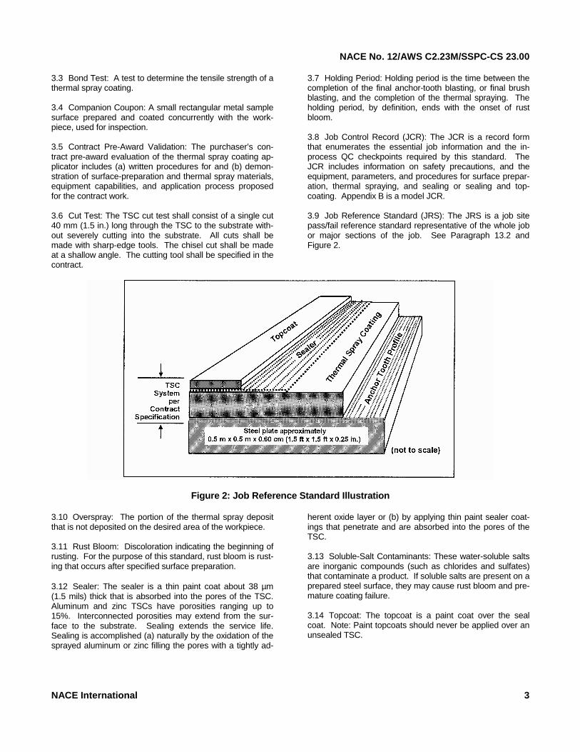
3.7 Holding Period: Holding period is the time between the completion of the final anchor-tooth blasting, or final brush blasting, and the completion of the thermal spraying. The holding period, by definition, ends with the onset of rust bloom. 3.8 Job Control Record (JCR): The JCR is a record form that enumerates the essential job information and the in-process QC checkpoints required by this standard. The JCR includes information on safety precautions, and the equipment, parameters, and procedures for surface prepar-ation, thermal spraying, and sealing or sealing and top-coating. Appendix B is a model JCR. 3.9 Job Reference Standard (JRS): The JRS is a job site pass/fail reference standard representative of the whole job or major sections of the job. See Paragraph 13.2 and Figure 2.
Figure 2: Job Reference Standard Illustration
3.10 Overspray: The portion of the thermal spray deposit that is not deposited on the desired area of the workpiece. 3.11 Rust Bloom: Discoloration indicating the beginning of rusting. For the purpose of this standard, rust bloom is rust-ing that occurs after specified surface preparation. 3.12 Sealer: The sealer is a thin paint coat about 38 µm (1.5 mils) thick that is absorbed into the pores of the TSC. Aluminum and zinc TSCs have porosities ranging up to 15%. Interconnected porosities may extend from the sur-face to the substrate. Sealing extends the service life. Sealing is accomplished (a) naturally by the oxidation of the sprayed aluminum or zinc filling the pores with a tightly ad-
herent oxide layer or (b) by applying thin paint sealer coat-ings that penetrate and are absorbed into the pores of the TSC. 3.13 Soluble-Salt Contaminants: These water-soluble salts are inorganic compounds (such as chlorides and sulfates) that contaminate a product. If soluble salts are present on a prepared steel surface, they may cause rust bloom and pre-mature coating failure. 3.14 Topcoat: The topcoat is a paint coat over the seal coat. Note: Paint topcoats should never be applied over an unsealed TSC.
NACE International 3
NACE No. 12/AWS C2.23M/SSPC-CS 23.00
________________________________________________________________________
Section 4: Summary of Practice
4.1 The procedure for application of TSCs for the corrosion protection of steel includes (a) proper surface preparation of the substrate steel, (b) proper application of the TSC, and (c) proper application of the sealer or sealer and topcoat. The procedure includes the use of suitable abrasive blast-ing, thermal spraying, sealing/topcoating equipment, and in-
process QC checkpoints. Table 1 summarizes the TSC system requirements and the inspection and acceptance tests for shop and field applications. The TSC system mat-erial, thickness, adhesion strength, and sealer or sealer and topcoat should be related to the required service.
________________________________________________________________________
Section 5: Surface Finish Requirements
5.1 Surface Finish
5.1.1 The steel substrate shall be prepared to: (1) White metal finish, NACE No. 1/SSPC-SP 5, for marine and immersion service, or (2) The minimum of near-white metal finish, NACE No, 2/SSPC-SP 10, for other service applications. (3) The level of soluble-salt contamination on the surface shall conform to the contract specifications. 5.1.2 Surface finish and cleanliness shall be confirmed according to SSPC-VIS 1.
5.2 Angular Profile Depth
5.2.1 The steel substrate shall have, at a minimum, an angular profile depth ≥65 µm (2.5 mils) with a sharp angular shape.
5.3 Angular Profile Depth Measurement Schedule
5.3.1 The profile depth shall be measured according to NACE Standard RP0287 or ASTM D 4417, Method C
(replica tape, x-coarse, 38 to 113 µm [1.5 to 4.5 mils]), or Method B (profile depth gauge), or both. (1) Manual Blasting. At a minimum, take one profile depth measurement every 1 to 2 m2 (10 to 20 ft2) of blasted surface. (2) Automated Blasting. At a minimum, take one profile depth measurement every 100 to 200 m2 (1,000 to 2,000 ft2) of blasted surface. (3) Angular Blast Media. Use clean dry angular blasting media. Mineral and slag abrasives shall be selected and evaluated per SSPC-AB 1, recycled fer-rous metallic abrasives per SSPC-AB 2, and steel grit per SSPC-AB 3. The absence of oil contamination shall be confirmed using the test for oil in the approp-riate abrasive specification (no oil film or slick). The soluble salt contamination shall be measured by ASTM D 4940. The suitability of the angular blast media, blast-ing equipment, and blasting procedures shall be vali-dated according to Section 14, Contract Pre-Award Evaluation, Demonstration, and Validation. Table 2 indicates blasting media and mesh size found suitable for TSCs on steel substrates.
________________________________________________________________________
Section 6: TSC Requirements
6.1 Feedstock and TSC Thickness6.1.1 The TSC feedstock material and thickness should be selected according to intended service envi-ronment and service life. (See ANSI/AWS C2.18) 6.1.2 The TSC feedstock material shall be specified according to ANSI/AWS C2.25/C2.25M or ASTM B 833.
6.1.3 The minimum and maximum TSC thickness shall be measured with an SSPC-PA 2, Type 2 fixed probe gauge or equivalent. The thickness scheduled is speci-fied in Paragraph 6.3.
4 NACE International
NACE No. 12/AWS C2.23M/SSPC-CS 23.00
NACE International 5
Table 1: TSC System Requirements and Acceptance Tests
TSC System Requirements Acceptance Tests
Surface Preparation
TSC Sealer or Sealer and Topcoat
NACE No. 2/SSPC-SP 10 minimum (A)
Smooth and uniform. No blisters, cracks, loose
particles, or exposed steel.
Smooth and uniform. No runs, sags, lifting, pinholes,
or overspray.
Per the contract surface preparation standard.
Angular-profile depth ≥65 µm (2.5
mils)
---
---
Profile tape according to NACE Standard RP0287
or micrometer depth gauge according to ASTM D 4417
Specify blasting media
Specify feedstock
Specify paint(s) Manufacturer’s certificate(B) and MSDS
--- Coating Thickness(C)
Minimum: ____µm (____mils) Maximum: ____µm (____mils)
Coating thickness Minimum: ____µm (____mils) Maximum: ____µm (____mils)
SSPC-PA 2 Type 2 Fixed Probe Gauge
--- Portable tensile bond
(≥ Table 3 values) Minimum: ____MPa (____psi)
---
ASTM D 4541(D)
Companion coupon bend/tensile-bond test(E): --- Bend/tensile-bond test
Condition of substrate surface preparation and TSC interface and morphology (structure)(F)
--- Metallographic
examination of companion coupon
--- No peeling or delimitation --- TSC Cut Test (G)
Other as specified by the Contract Other as specified by the Contract
___________________________ (A) For critical surfaces and marine and underwater service, clean to a white metal finish (NACE No. 1/SSPC-SP 5) with ≥65 µm (2.5 mils) angular profile. The owner should specify the minimum required blast quality and its validation according to Section 5, Job Reference Standard. The angularity of the blast profile can be determined by a metallographic analysis of a companion coupon according to ASTM E 3 using a specimen cut from a successful bend coupon prepared and thermal sprayed per the contract specifications and tested according to Paragraph 6.5. (B) Verification that the manufacturers or suppliers provide a certificate or affidavit that (1) the blasting media conforms to SSPC-AB 1 for mineral and slag abrasive, SSPC-AB 2 for recycled ferrous metallic abrasives, or SSPC-AB 3 for newly manufactured or remanufactured steel abrasive; (2) the TSC-feedstock chemical composition, obtained from a representative sample of each heat during the pouring or subsequent processing, conforms to ANSI/AWS C2.25; and (3) the sealer and topcoat paints are formulated for the contract-specified thermal spray coating. The Material Safety Data Sheets (MSDS) provide supporting physical and chemical information. (C) Measure the TSC thickness according to SSPC-PA 2. Calibrate the instrument using a calibration wedge near the contract-specified thickness placed over a representative sample of the contract-specified abrasive blasted steel, a prepared bend coupon, or both. (D) Specify the ASTM D 4541 self-adjusting portable tensile instrument to be used and its minimum acceptable value for the Job Reference Standard and the job work surfaces. (E) As an alternative to the portable tensile-bond test, which may be considered potentially destructive on a finished part, a companion coupon may be bend tested, or a companion tensile test specimen may be tested in accordance with ASTM C 633 to validate the coating adhesion strength. The bend test is a macro system test for proper surface preparation, equipment set-up, and spraying parameters. (F) Metallographic analysis of a companion coupon may be specified to establish the suitability of the surface preparation, TSC application, and/or porosity of the TSC. (G) TSC cut test should be made by a tool cutting through the TSC to the steel surface. The TSC is defective if any part of the coating lifts off the surface.
NACE No. 12/AWS C2.23M/SSPC-CS 23.00
Table 2: Blasting Media and Mesh Size Found Suitable for TSCs on Steel Substrates
Thermal Spray Material Process Blasting Media Size(A)
Aluminum oxide 10-30 mesh
Angular steel grit G-16 to G-40
Copper and nickel slag G-16 to G-24
Almandite garnet G-16 to 30/40
Al, Zn, 85/15 Zn/Al, 90/10 Al-Al2 O3 MMC Flame wire and arc wire
Chilled iron grit G-16 to G-40
Aluminum oxide 10-30 mesh
Angular steel grit G-16 to G-40 Al, Zn Flame powder
Chilled iron grit G-16 to G-40 (A) Mesh size shall be selected as appropriate to the anchor-tooth depth requirement and the blasting equipment used.
6.2 TSC Thickness
6.2.1 Thickness Less Than Contract Specification
6.2.1.1 If upon later inspection, and prior to sealer application, the TSC thickness is less than the contract requirement, the applicator shall apply ad-ditional TSC to meet the thickness requirement.
6.2.2 Thickness Greater Than Contract Specification
6.2.2.1 If the TSC thickness is greater than the contract specification, information shall be record-ed in the JCR and the inspector shall be notified immediately. The inspector should then notify the purchaser for resolution of this discrepancy. The TSC applicator and the purchaser should record all areas in excess of 150% of the acceptable coating thickness. If these areas are damaged during shipping, loading/unloading, or erection, they should be repaired in accordance with main-tenance repair procedures as outlined in ANSI/ AWS C2.18.
6.3 TSC Thickness Measurement Schedule
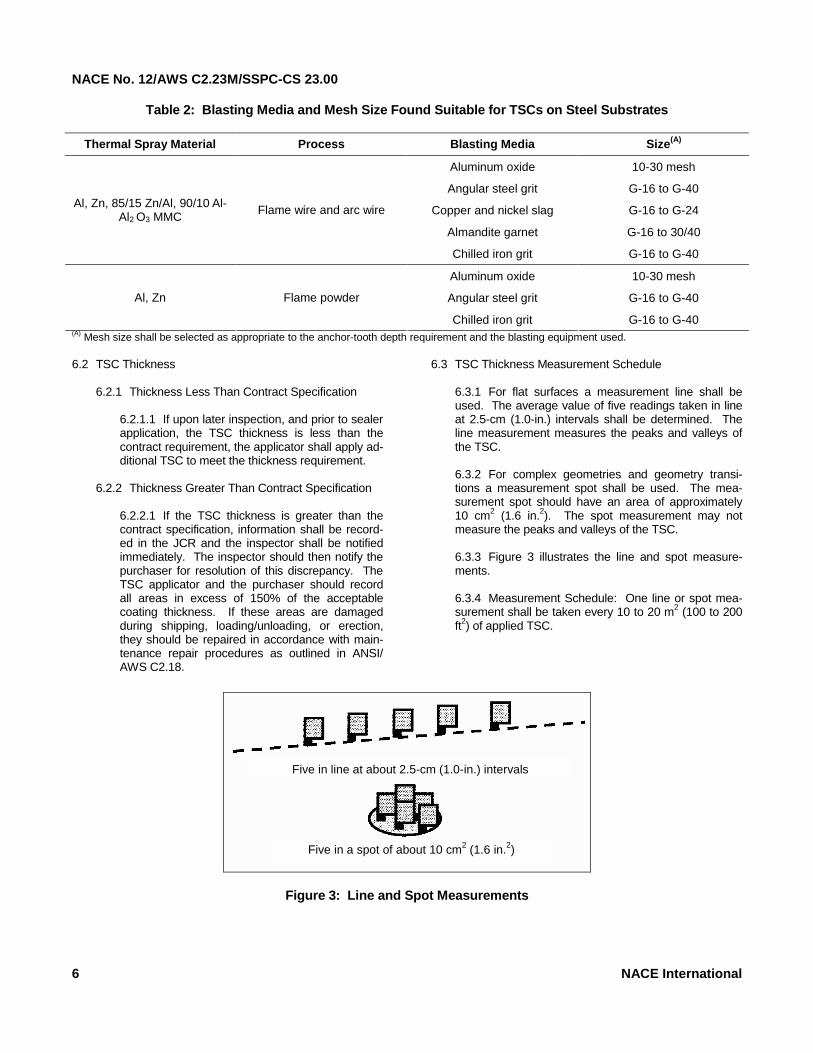
6.3.1 For flat surfaces a measurement line shall be used. The average value of five readings taken in line at 2.5-cm (1.0-in.) intervals shall be determined. The line measurement measures the peaks and valleys of the TSC. 6.3.2 For complex geometries and geometry transi-tions a measurement spot shall be used. The mea-surement spot should have an area of approximately 10 cm2 (1.6 in.2). The spot measurement may not measure the peaks and valleys of the TSC. 6.3.3 Figure 3 illustrates the line and spot measure-ments. 6.3.4 Measurement Schedule: One line or spot mea-surement shall be taken every 10 to 20 m2 (100 to 200 ft2) of applied TSC.
6 NACE International
Figure 3: Line and Spot Measurements
Five in line at about 2.5-cm (1.0-in.) intervals
Five in a spot of about 10 cm2 (1.6 in.2)
NACE No. 12/AWS C2.23M/SSPC-CS 23.00
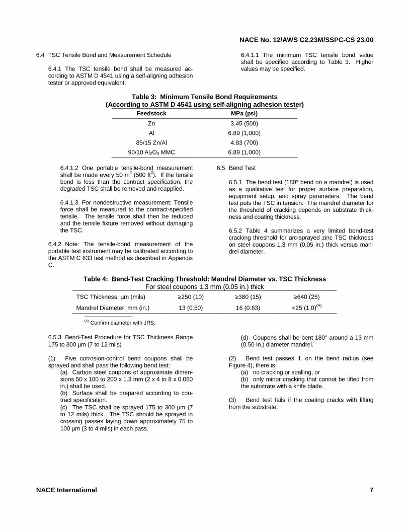
6.4 TSC Tensile Bond and Measurement Schedule
6.4.1 The TSC tensile bond shall be measured ac-cording to ASTM D 4541 using a self-aligning adhesion tester or approved equivalent.
6.4.1.1 The minimum TSC tensile bond value shall be specified according to Table 3. Higher values may be specified.
Table 3: Minimum Tensile Bond Requirements
(According to ASTM D 4541 using self-aligning adhesion tester) Feedstock MPa (psi)
Zn 3.45 (500)
Al 6.89 (1,000)
85/15 Zn/Al 4.83 (700)
90/10 Al2O3 MMC 6.89 (1,000)
6.4.1.2 One portable tensile-bond measurement shall be made every 50 m2 (500 ft2). If the tensile bond is less than the contract specification, the degraded TSC shall be removed and reapplied. 6.4.1.3 For nondestructive measurement: Tensile force shall be measured to the contract-specified tensile. The tensile force shall then be reduced and the tensile fixture removed without damaging the TSC.
6.4.2 Note: The tensile-bond measurement of the portable test instrument may be calibrated according to the ASTM C 633 test method as described in Appendix C.
6.5 Bend Test
6.5.1 The bend test (180° bend on a mandrel) is used as a qualitative test for proper surface preparation, equipment setup, and spray parameters. The bend test puts the TSC in tension. The mandrel diameter for the threshold of cracking depends on substrate thick-ness and coating thickness. 6.5.2 Table 4 summarizes a very limited bend-test cracking threshold for arc-sprayed zinc TSC thickness on steel coupons 1.3 mm (0.05 in.) thick versus man-drel diameter.
Table 4: Bend-Test Cracking Threshold: Mandrel Diameter vs. TSC Thickness
For steel coupons 1.3 mm (0.05 in.) thick
TSC Thickness, µm (mils) ≥250 (10) ≥380 (15) ≥640 (25)
Mandrel Diameter, mm (in.) 13 (0.50) 16 (0.63) <25 (1.0)(A) __________________________
(A) Confirm diameter with JRS.
6.5.3 Bend-Test Procedure for TSC Thickness Range 175 to 300 µm (7 to 12 mils) (1) Five corrosion-control bend coupons shall be sprayed and shall pass the following bend test:
(a) Carbon steel coupons of approximate dimen-sions 50 x 100 to 200 x 1.3 mm (2 x 4 to 8 x 0.050 in.) shall be used. (b) Surface shall be prepared according to con-tract specification. (c) The TSC shall be sprayed 175 to 300 µm (7 to 12 mils) thick. The TSC should be sprayed in crossing passes laying down approximately 75 to 100 µm (3 to 4 mils) in each pass.
(d) Coupons shall be bent 180° around a 13-mm (0.50-in.) diameter mandrel.
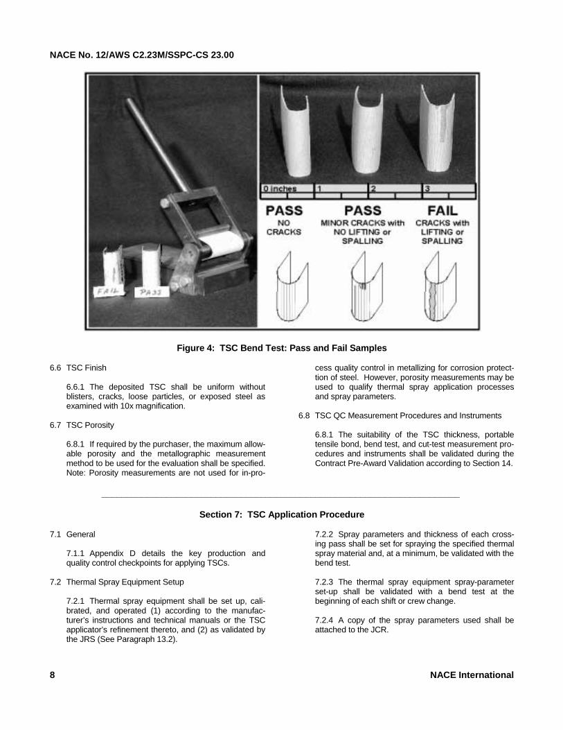
(2) Bend test passes if, on the bend radius (see Figure 4), there is
(a) no cracking or spalling, or (b) only minor cracking that cannot be lifted from the substrate with a knife blade.
(3) Bend test fails if the coating cracks with lifting from the substrate.
NACE International 7
NACE No. 12/AWS C2.23M/SSPC-CS 23.00
Figure 4: TSC Bend Test: Pass and Fail Samples
6.6 TSC Finish6.6.1 The deposited TSC shall be uniform without blisters, cracks, loose particles, or exposed steel as examined with 10x magnification.
6.7 TSC Porosity
6.8.1 If required by the purchaser, the maximum allow-able porosity and the metallographic measurement method to be used for the evaluation shall be specified. Note: Porosity measurements are not used for in-pro-
cess quality control in metallizing for corrosion protect-tion of steel. However, porosity measurements may be used to qualify thermal spray application processes and spray parameters.
6.8 TSC QC Measurement Procedures and Instruments
6.8.1 The suitability of the TSC thickness, portable tensile bond, bend test, and cut-test measurement pro-cedures and instruments shall be validated during the Contract Pre-Award Validation according to Section 14.
________________________________________________________________________
Section 7: TSC Application Procedure
7.1 General
7.1.1 Appendix D details the key production and quality control checkpoints for applying TSCs.
7.2 Thermal Spray Equipment Setup
7.2.1 Thermal spray equipment shall be set up, cali-brated, and operated (1) according to the manufac-turer’s instructions and technical manuals or the TSC applicator’s refinement thereto, and (2) as validated by the JRS (See Paragraph 13.2).
7.2.2 Spray parameters and thickness of each cross-ing pass shall be set for spraying the specified thermal spray material and, at a minimum, be validated with the bend test. 7.2.3 The thermal spray equipment spray-parameter set-up shall be validated with a bend test at the beginning of each shift or crew change. 7.2.4 A copy of the spray parameters used shall be attached to the JCR.
8 NACE International
NACE No. 12/AWS C2.23M/SSPC-CS 23.00
7.3 Post-Blasting Substrate Condition and Thermal Spray-ing Period
7.3.1 Steel Surface Temperature
7.3.1.1 The steel surface temperature shall be at least 3°C (5°F) above the dewpoint of the ambient air temperature.
7.3.2 Holding Period
7.3.2.1 Time between the completion of the final anchor-tooth blasting (or final brush blasting) and the completion of the thermal spraying should be no greater than six hours for steel substrates with the following exceptions: (1) In high-humidity and damp environments, shorter holding periods shall be used. If rust bloom or a degraded coating appears at any time while spraying, spraying shall be stopped. (See Paragraph 8.2.4.) (2) In low-humidity environments or in controlled environments with enclosed structures using industrial dehumidification equipment, it may be possible to retard the oxidation of the steel and hold the surface finish for more than six hours. The TSC applicator, with the concurrence of the purchaser, can establish a holding period greater than six hours by determining the acceptable tem-perature-humidity envelope for the work enclosure by spraying and analyzing bend coupons, tensile-bond specimens, or both. The following method shall be used for bend-test coupons: (a) establish, measure, and record the low-humidity environ-ment; (b) prepare four bend-test coupons accord-ing to contract specifications; (c) place bend-test coupons in the low-humidity environment; (d) after target holding period duration, apply the contract-specified thermal spray coating; (e) perform the bend test according to Paragraph 6.5; (f) the low-humidity environment and holding period are satis-factory if the four bend coupons meet the require-ment of Paragraph 6.6.3 (2). Alternately, tensile-bond specimens can be similarly tested.
(3) For small and movable parts, if more than 15 minutes is expected to elapse between the com-pletion of surface preparation and the start of ther-mal spraying, or if the part is moved to another location, the prepared surface should be protected from moisture, contamination, and finger/hand marks. Wrapping with clean ink-free paper is nor-mally adequate.
7.4 TSC Flash Coat
7.4.1 Application Time
7.4.1.1 A 25- to 50-µm (1- to 2-mil) flash coat of the TSC may be applied within six hours of com-pleting surface preparation to extend the holding period for up to four more hours beyond the com-plete application of the flash coat. The final TSC thickness, however, shall be applied within four hours of the completion of the application of the flash coat provided the TSC can be maintained free of contamination.
7.4.2 Validation Procedure
7.4.2.1 The use of a flash TSC to extend the hold-ing period shall be validated with a tensile-bond measurement, bend test, or both. The use of a flash TSC shall be validated by: (1) Cleaning and abrasive blasting a representa-tive job area for a portable tensile-bond measure-ment, a bend-test coupon, or both. (2) Applying a flash TSC. (3) Waiting the delay period and applying the final TSC thickness. (4) Measuring the tensile bond, performing the bend test, or both. 7.4.2.2 The flash TSC and holding period are acceptable if the tensile bond, bend tests, or both, are satisfactory.
________________________________________________________________________
Section 8: TSC Application
8.1 Preheat8.1.1 Preheating the starting area has been common practice for flame spraying and should be continued until proven not to be a benefit or inconsequential. The initial 0.1- to 0.2-m2 (1- to 2-ft2) starting-spray area shall be preheated to prevent water in the flame from con-densing on the substrate.
8.1.1.1 For flame spraying, the initial starting area shall be preheated to approximately 120°C (250°F). 8.1.1.2 Preheating requirements shall be vali-dated with the JRS and the bend test, tensile test, or both.
NACE International 9
NACE No. 12/AWS C2.23M/SSPC-CS 23.00
8.2 Thermal Spraying8.2.1 Crossing Passes
8.2.1.1 The specified coating thickness shall be applied in several crossing passes. The coating tensile-bond strength is greater if the spray passes are kept thin. Laying down an excessively thick spray pass increases the internal stresses in the TSC and decreases the ultimate tensile-bond strength of the total TSC. The suitability of the crossing-pass thickness shall be confirmed with a bend test, tensile-bond measurement, or both.
8.2.2 Manual Spraying
8.2.2.1 For manual spraying, right-angle crossing passes shall be used to minimize the thin areas in the coating.
8.2.3 Mechanized Spraying
8.2.3.1 For mechanized spraying (mechanized movement of the gun, workpiece, or both), over-lapping and crossing passes shall be programmed to eliminate thin spots and stay within the coating thickness specification.
8.2.4 Rust Bloom
8.2.4.1 If rust bloom, blistering, or a degraded coating appears at any time during the application of the TSC or flash TSC, the following procedure applies: (1) Stop spraying.
(2) Mark off the acceptable sprayed area. (3) Re-prepare the unsatisfactory areas to the re-quired degree of surface cleanliness and surface profile, including any areas where the TSC was applied to unsatisfactory surfaces.
(a) Blast the edges of the TSC to provide for a 5.0- to 7.5-cm (2.0- to 3.0-in.) feathered-area overlap of the new work into the existing TSC. (b) Apply TSC to the newly prepared sur-faces, and overlap the existing TSC to the ex-tent of the feathered edge so that the overlap is a consistent thickness.
8.2.5 TSC Thickness
8.2.5.1 The TSC thickness shall be that specified in Table 1 and Paragraph 6.1.3.
8.2.6 Low-Temperature Spraying
8.2.6.1 Thermal spraying in low-temperature envi-ronments (below freezing) must: (1) Meet the substrate surface temperature and holding period specified in Paragraphs 7.3.1 and 7.3.2. No moisture condensation on the surface is permissible during thermal spraying. (2) Be qualified with a bend test, portable tensile-bond test, or both. Note: TSCs are mechanically bonded to the sub-strate. Preheating may be required to improve the TSC tensile bond to the substrate and reduce internal stresses.
________________________________________________________________________
Section 9: Application of Sealers and Topcoats
9.1 General
9.1.1 Thermal sprayed steel should be sealed and/or topcoated under any of the following conditions: (1) The environment is very acidic or very alkaline (normal pH range for pure zinc is 6 to 12 and for pure aluminum, 4 to 11). (2) The metallic coating is subject to direct attack by specific chemicals. (3) A particular decorative finish is required. (4) Additional abrasion resistance is required. (5) Frequent saltwater spray, splash, or immersion service.
(6) Frequent freshwater spray, splash, or immersion service, excluding potable water. 9.1.2 Sealers and topcoats shall meet the local restrictions on volatile organic compound (VOC) con-tent. Sealer and topcoats shall be applied according to the paint manufacturer’s instructions for use with a TSC, or as specified by the purchaser.
9.2 Sealer
9.2.1 The seal coat, if applied, shall be thin enough to penetrate into the body of the TSC and seal the inter-connected surface porosity. Typically the seal coat is applied at a spreading rate resulting in a theoretical 38-µm (1.5-mil) dry-film thickness (DFT).
10 NACE International
NACE No. 12/AWS C2.23M/SSPC-CS 23.00
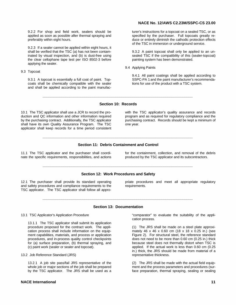
9.2.2 For shop and field work, sealers should be applied as soon as possible after thermal spraying and preferably within eight hours. 9.2.3 If a sealer cannot be applied within eight hours, it shall be verified that the TSC (a) has not been contam-inated by visual inspection, and (b) is dust-free using the clear cellophane tape test per ISO 8502-3 before applying the sealer.
9.3 Topcoat
9.3.1 A topcoat is essentially a full coat of paint. Top-coats shall be chemically compatible with the sealer and shall be applied according to the paint manufac-
turer’s instructions for a topcoat on a sealed TSC, or as specified by the purchaser. Full topcoats greatly re-duce or entirely diminish the cathodic protection effects of the TSC in immersion or underground service. 9.3.2 A paint topcoat shall only be applied to an un-sealed TSC if the compatibility of this (sealer-topcoat) painting system has been demonstrated.
9.4 Applying Paints
9.4.1 All paint coatings shall be applied according to SSPC-PA 1 and the paint manufacturer’s recommenda-tions for use of the product with a TSC system.
________________________________________________________________________
Section 10: Records
10.1 The TSC applicator shall use a JCR to record the pro-duction and QC information and other information required by the purchasing contract. Additionally, the TSC applicator shall have its own Quality Assurance Program. The TSC applicator shall keep records for a time period consistent
with the TSC applicator’s quality assurance and records program and as required for regulatory compliance and the purchasing contract. Records should be kept a minimum of one year.
________________________________________________________________________
Section 11: Debris Containment and Control
11.1 The TSC applicator and the purchaser shall coordi-nate the specific requirements, responsibilities, and actionsfor the containment, collection, and removal of the debris produced by the TSC applicator and its subcontractors.
________________________________________________________________________
Section 12: Work Procedures and Safety
12.1 The purchaser shall provide its standard operating and safety procedures and compliance requirements to the TSC applicator. The TSC applicator shall follow all appro-
priate procedures and meet all appropriate regulatory requirements.
________________________________________________________________________
Section 13: Documentation
13.1 TSC Applicator’s Application Procedure13.1.1 The TSC applicator shall submit its application procedure proposed for the contract work. The appli-cation process shall include information on the equip-ment capabilities, materials, and process or application procedures, and in-process quality control checkpoints for (a) surface preparation, (b) thermal spraying, and (c) paint work (sealer or sealer and topcoat).
13.2 Job Reference Standard (JRS)
13.2.1 A job site pass/fail JRS representative of the whole job or major sections of the job shall be prepared by the TSC applicator. The JRS shall be used as a
“comparator” to evaluate the suitability of the appli-cation process. (1) The JRS shall be made on a steel plate approxi-mately 46 x 46 x 0.60 cm (18 x 18 x 0.25 in.) (see Figure 2). For structural steel, the reference standard does not need to be more than 0.60 cm (0.25 in.) thick because steel does not thermally distort when TSC is applied. If the actual work is less than 0.60 cm (0.25 in.) thick, the JRS should be made from material of a representative thickness. (2) The JRS shall be made with the actual field equip-ment and the process parameters and procedures (sur-face preparation, thermal spraying, sealing or sealing
NACE International 11
NACE No. 12/AWS C2.23M/SSPC-CS 23.00
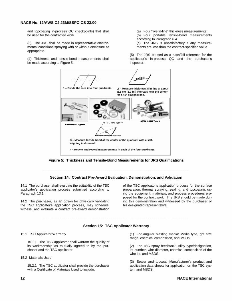
and topcoating in-process QC checkpoints) that shall be used for the contracted work. (3) The JRS shall be made in representative environ-mental conditions spraying with or without enclosure as appropriate. (4) Thickness and tensile-bond measurements shall be made according to Figure 5.
(a) Four “five in-line” thickness measurements. (b) Four portable tensile-bond measurements according to Paragraph 6.4. (c) The JRS is unsatisfactory if any measure-ments are less than the contract-specified value.
(5) The JRS is used as a pass/fail reference for the applicator’s in-process QC and the purchaser’s inspector.
Figure 5: Thickness and Tensile-Bond Measurements for JRS Qualifications
1- Divide the area into four quadrants. 2- Measure thickness, 5 in-line at about 1-in, [2.5 cm] intervals near the center of a 45o
diagonal line.
3- Measure tensile bond at the center of the quadrant with a self-aligning instrument.
4- Repeat & record measurements in each of the four quadrants.
X
ASTM D 4541 Type IIIASTM D 4541 Type IV
ASTM D 4541 Type V
1- Divide the area into four quadrants. 2- Measure thickness, 5 in-line at about 1-in, [2.5 cm] intervals near the center of a 45o
diagonal line.
1- Divide the area into four quadrants.1- Divide the area into four quadrants. 2- Measure thickness, 5 in-line at about 1-in, [2.5 cm] intervals near the center of a 45o
diagonal line.
3- Measure tensile bond at the center of the quadrant with a self-aligning instrument.
4- Repeat & record measurements in each of the four quadrants.
X
ASTM D 4541 Type IIIASTM D 4541 Type IV
ASTM D 4541 Type V
XXX
ASTM D 4541 Type IIIASTM D 4541 Type IV
ASTM D 4541 Type V
2 – Measure thickness, 5 in line at about 2.5-cm (1.0-in.) intervals near the center of a 45° diagonal line.
1 – Divide the area into four quadrants.
4 – Repeat and record measurements in each of the four quadrants.
3 – Measure tensile bond at the center of the quadrant with a self-aligning instrument.
________________________________________________________________________
Section 14: Contract Pre-Award Evaluation, Demonstration, and Validation
14.1 The purchaser shall evaluate the suitability of the TSC applicator’s application process submitted according to Paragraph 13.1. 14.2 The purchaser, as an option for physically validating the TSC applicator’s application process, may schedule, witness, and evaluate a contract pre-award demonstration
of the TSC applicator’s application process for the surface preparation, thermal spraying, sealing, and topcoating, us-ing the equipment, materials, and process procedures pro-posed for the contract work. The JRS should be made dur-ing this demonstration and witnessed by the purchaser or his designated representative.
________________________________________________________________________
Section 15: TSC Applicator Warranty
15.1 TSC Applicator Warranty15.1.1 The TSC applicator shall warrant the quality of its workmanship as mutually agreed to by the pur-chaser and the TSC applicator.
15.2 Materials Used
15.2.1 The TSC applicator shall provide the purchaser with a Certificate of Materials Used to include:
(1) For angular blasting media: Media type, grit size range, chemical composition, and MSDS. (2) For TSC spray feedstock: Alloy type/designation, lot number, wire diameter, chemical composition of the wire lot, and MSDS. (3) Sealer and topcoat: Manufacturer’s product and application data sheets for application on the TSC sys-tem and MSDS.
12 NACE International
NACE No. 12/AWS C2.23M/SSPC-CS 23.00
________________________________________________________________________
Further Reading
ANSI Z49.1. “Safety in Welding, Cutting, and Allied Pro-cesses.” Washington, DC: ANSI.(10) AWS C2.14. “Corrosion Tests of Flame-Sprayed Coated
Steel, 19-Year Report.” 1974.(11) BS 5493. “Code of Practice for Protective Coatings of Iron
and Steel Structures Against Corrosion.” London, UK: BSI.(12)
Kain, R.M., and E.A. Baker. “Marine Atmospheric Corrosion
Museum Report on the Performance of Thermal Spray Coatings on Steel.” ASTM STP 947. 1987.
NFPA 58. “Standard for the Storage and Handling of Lique-
fied Petroleum Gases.” Quincy, MA: NFPA.(13)
Pikul, S.J. “Appearance of Thermal Sprayed Coatings after 44 Years Marine Atmospheric Exposure at Kure Beach, North Carolina.” LaQue Center for Corrosion Technology Report.(14)
SSPC Publication. Inspection of Coatings and Linings: A
Handbook of Basic Practice for Inspectors, Owners, and Specifiers. B.R. Appleman, R. Drisko, J. Neugebauer, eds.
SSPC-TU 4. “Field Methods for Retrieval and Analysis of
Soluble Salts on Substrates.” Pittsburgh, PA: SSPC. Thermal Spraying: Practice, Theory, and Application.
Miami, FL: AWS, 1985.(15)
NACE International 13
___________________________
(10) Available from the American National Standards Institute, 1819 L Street NW, 6th floor, Washington, DC 20036. (11) AWS publications can be obtained from Global Engineering, 15 Inverness Way East, Engelwood, CO 80112-5776, Telephone (800)-854-7179, Fax (303) 307-2740, Internet www .global.ihs.com. (12) BSI standards can be obtained from the British Standards Institution (BSI), British Standards House, 389 Chiswick High Rd., London W4 4AL, UK. (13) Available from the National Fire Protection Association, 1 Batterymarch Park, P.O. Box 9101, Quincy, MA 02269-9101. (14) Available from the LaQue Center for Corrosion Technology, Inc., 702 Causeway Drive, Wrightsville Beach, NC 28480. (15) AWS publications can be obtained from Global Engineering, 15 Inverness Way East, Engelwood, CO 80112-5776, Telephone (800)-854-7179, Fax (303) 307-2740, Internet www .global.ihs.com

NACE No. 12/AWS C2.23M/SSPC-CS 23.00
14 NACE International
________________________________________________________________________
Appendix A: Model Procurement Specification This Appendix is not a part of NACE No. 12/AWS C2.23M/SSPC-CS 23.00, but is included for informational purposes only. Appendix A is included to illustrate how this standard may be used to specify a thermal spray job.
The Model Specification (Bolded text is the model specification. Scripted text is optional and if used,
should match the format and style used in the final specification.)
Instructions/Rationale
1. Scope of Work 1.1 Application Procedure The TSC system (surface preparation, thermal spraying, and sealing or seal-ing and topcoating) shall be applied in accordance with Sections 4, 5, and 6 of this specification.
The major production and quality con-trol (QC) steps for applying a TSC coating system are summarized in Appendix D. Appendix D should be appended to the procurement specifi-cation to inform the TSC applicator of the application requirements.
1.2 Items/Areas to Be Thermal Sprayed. Apply TSC systems to: ____________________________________________________________________________________________________________________________________________________________________________________________________________________________________________________________________
Specify the item(s) and surface(s) to be (and not to be) thermal sprayed. Reference and append engineering drawings or other technical documents that quantitatively describe the job.
2. Codes and Standards This specification takes precedence in event of conflict with cited Codes and Standards.
The following codes and standards (latest issue) apply: ASTM B 833, Standard Specification for Zinc Wire for Thermal Spraying (Metal-
lizing). ASTM C 633, Test Method for Adhesive/Cohesive Strength of Flame Sprayed
Coatings. ASTM D 4285, Method for Indicating Oil or Water in Compressed Air. ASTM D 4417, Test Method for Field Measurement of Surface Profile of Blasted
Steel. NACE Standard RP0287, Field Measurement of Surface Profile of Abrasive Blast
Cleaned Steel Surfaces Using a Replica Tape. ASTM D 4541, Test Method for Pull-Off Strength of Coating Using Portable Adhe-
sion Testers. ANSI/AWS C2.18, Guide for the Protection of Steel with Thermal Spray Coatings
of Aluminum, Zinc, and Their Alloys and Composites. NACE No. 12/AWS C2.23M/SSPC-CS 23.00, Specification for the Application of
Thermal Spray Coatings (Metallizing) of Aluminum, Zinc, and Their Alloys and Composites for the Corrosion Protection of Steel.
SSPC Publication, The Inspection of Coatings and Linings: A Handbook of Basic Practice for Inspectors, Owners, and Specifiers.
SSPC-AB 1, Mineral and Slag Abrasives. SSPC-AB 3, Ferrous Metallic Abrasives. SSPC-PA 1, Shop, Field, and Maintenance Painting of Steel. SSPC-PA 2, Measurement of Dry Coating Thickness with Magnetic Gages. NACE No. 1/SSPC-SP 5, White Metal Blast Cleaning. NACE No. 2/SSPC-SP 10, Near-White Metal Blast Cleaning. SSPC-VIS 1, Guide and Reference Photographs for Steel Surfaces Prepared by
Dry Abrasive Blast Cleaning.
List the Codes and Standards cited in this procurement specification. Add other standards as required.
NACE No. 12/AWS C2.23M/SSPC-CS 23.00
NACE International 15
The Model Specification (Bolded text is the model specification. Scripted text is optional and if used,
should match the format and style used in the final specification.)
Instructions/Rationale
3. TSC System Requirements
3.1 Surface Preparation Requirement.
3.1.1 Surface Finish. Degrease according to SSPC-SP 1 if oil/grease contaminated. The steel substrate shall be abrasive blasted to ______(a)______. Using SSPC VIS 1, confirm that the blast cleaned finish meets NACE No. 1/SSPC-SP 5 or NACE No. 2/SSPC-SP 10.
(a) Specify either white metal finish, NACE No. 1/SSPC-SP 5, for marine and immersion service; or near-white metal finish, NACE No. 2/SSPC-SP 10, for other service applications.
3.1.2 Blasting Media Requirement. Use ____(a)___ angular blasting media to produce the angular profile depth specified by Paragraph 3.1.3. Mineral and slag abrasives shall be selected and evaluated per SSPC-AB 1; recycled ferrous metallic abrasives per SSPC-AB 2; and steel grit per SSPC-AB 3.
(a) Specify abrasive basting media type and size. See Table 2 of this NACE No. 12/AWS C2.23M/SSPC-CS 23.00 standard.
3.1.3 Blast Angular Profile Depth. The steel substrate shall have an angular profile depth ≥≥≥≥65 µµµµm (2.5 mils) with a sharp angular shape per NACE Standard RP0287 or ASTM D 4417, Method B or C.
3.1.4 Blast Profile Measurement Schedule. Measure the angular profile depth in a measurement spot approximately every ____(a)____ blasted surface. Take three measurements for each spot in an area approximately 10 cm2 (1.5 in.2). Average the measurements and record in the JCR.
(a) Specify the minimum area, e.g., 10 to 20 m2 (100 to 200 ft2)
3.2 TSC Requirement.
3.2.1 Thermal Spray Feedstock Requirement. Use (a) thermal spray wire.
(a) Specify wire according to ANSI/ AWS C2.25 or ASTM B 833.
3.2.2 TSC Thickness Requirement and Measurement Schedule (a) Thickness
(1) The minimum TSC thickness shall be ______(a)______. (2) The maximum TSC thickness shall be ______(b)______. (3) Measure TSC thickness using a SSPC-PA 2 Type 2 fixed probe
gauge or equivalent.
(b) Measurement Schedule One portable tensile-bond measurement shall be made every 50 m2 (500 ft2). If the tensile bond is less than the contract specification, the degraded TSC shall be removed and reapplied.
(a) Specify the minimum thickness. (b) Specify the maximum thickness.
3.2.3 TSC Tensile-Bond Requirement. (a) The TSC shall have a minimum tensile bond of __(a)__ MPa (____ psi) according to ASTM D 4541 using the Type _(b)__ self-aligning portable test instrument for coating thickness specified in Paragraph 3.2.2.
(b) Use adhesive recommended by the instrument manufacturer, or equiv-alent. Attach adhesive manufacturer’s instructions to the JCR.
(a) Specify the minimum tensile bond. (b) Specify either the Type III or IV por-table self-aligning test instruments.
NACE No. 12/AWS C2.23M/SSPC-CS 23.00
16 NACE International
The Model Specification (Bolded text is the model specification. Scripted text is optional and if used,
should match the format and style used in the final specification.)
Instructions/Rationale
3.2.4 Bend Test. Conduct a bend test at the beginning of each work shift or crew change: (1) Use carbon steel coupons of approximate dimensions 50 x 100 to 200 x 1.3 mm (2 x 4 to 8 x 0.050 in.). (2) Surface preparation according to contract specification. (3) Spray 200- to 250-µµµµm (8- to 10-mil) thick TSC in crossing passes laying down approximately 75 to 100 µµµµm (3 to 4 mils) for each pass. (4) Bend coupons 180°°°° around a 13-mm (0.5-in.) diameter mandrel.
(a) Bend test passes if there is no cracking or only minor cracks with no spalling or lifting (by a knife blade) from the substrate. (b) Bend test fails if the coating cracks with lifting (by a knife blade) from the substrate.
The bend test (180° bend on a man-drel) is used as a qualitative test for proper surface preparation, equipment setup, and spray parameters. The bend test puts the TSC in tension. The mandrel diameter for the threshold of cracking depends on substrate thick-ness, coating thickness, and mandrel diameter.
3.2.5 TSC Porosity Requirement. The TSC shall have a porosity ≤ __(a)__ % for each metallographic analysis of a bend coupon made during the Contract Pre-Award Evaluation, Demonstration, and Validation.
Flame and arc spraying aluminum and zinc for the corrosion protection of steel generally have porosity ≤15%. The TSC thickness should be selected so there is no interconnected porosity to the substrate. A lower-porosity TSC requires less thickness. Porosity meas-urements are not used for in-process quality control in metallizing for corro-sion protection of steel. However, a metallographic sample must be used to evaluate TSC porosity and confirm the TSC nonporous thickness for the contract-specified thickness. If re-quired, the porosity metallographic sample should be taken from the bend coupon made during the purchaser’s witnessing of the preparation of the JRS.
3.3 Sealers and Topcoats All paint coatings shall be applied according to SSPC-PA 1 and the paint manu-facturer’s instructions for use of the product with a thermal sprayed coating system. Use a heat-resistant silicone alkyd aluminum paint or equivalent sealer on components whose operating temperatures are greater than 80°C (175°F).
Specify use of sealer if (a) the service environment precludes effectiveness of the natural oxidation to “fill and seal” the pores or (b) a paint topcoat (cos-metic and/or functional purpose) is specified. Long delay times will pre-clude adequate penetration of the seal-er into the pores of the TSC. The seal-er must be chemically compatible with the TSC material and the topcoat.

NACE No. 12/AWS C2.23M/SSPC-CS 23.00
NACE International 17
The Model Specification (Bolded text is the model specification. Scripted text is optional and if used,
should match the format and style used in the final specification.)
Instructions/Rationale
3.3.1 Sealer (1) Use the sealer ______(a)______ manufactured by______(b)______. (2) Follow paint manufacturer’s application instructions for applying the sealer on TSCs. The seal coat shall be thin enough to penetrate into the body of the TSC and seal the porosity. Typically the seal coat is applied at a spreading rate result-ing in a theoretical 38-µm (1.5-mil) DFT. (3) Sealer Application For shop work, apply the sealer immediately after thermal spraying. For field work, apply the sealer as soon after thermal spraying as possible but preferably within eight hours. If sealer cannot be applied within eight hours, verify that the TSC (a) has not been contaminated by visual (10x) inspection and (b) is dust-free using the clear cello-phane tape test (ISO 8502-3).
(a) Specify formula or other unique identification. (b) Specify manufacturer.
3.3.2 Topcoat. (1) Use the topcoat ______(a)______ manufactured by______(b)_____. (2) Apply the topcoat to a dry-film thickness (DFT) of ____(c)___ according to manufacturer’s instructions. (3) Measure DFT using an SSPC-PA 2 Type 2 fixed probe gauge.
(a) Specify formula or other unique identification. (b) Specify manufacturer. (c) Specify thickness from similar suc-cessful applications or manufacturer’s recommendations for topcoating seal-ers on TSCs.
4. Surface Preparation. Use blasting equipment, materials, and procedures that will produce the Paragraph 3.1 metal finish and an angular profile ≥≥≥≥65 µµµµm (2.5 mils). The suitability of the blasting, media, procedures, and equipment shall be vali-dated in the contract pre-award evaluation, demonstration, and validation.
Blasting media is specified in Para-graph 3.1.2.
5. TSC Application.
5.1 Thermal Spray Equipment Setup. 5.1.1 Thermal spray equipment shall be set up, calibrated, and operated according to the manufacturer’s instructions and technical manuals or the TSC applicator’s refinement thereto and as validated by the JRS. 5.1.2 Spray parameters shall be set for spraying the specified thermal spray material and, at a minimum, be validated with the bend test. A bend test shall be satisfactorily performed at the beginning of crew and shift change. 5.1.3 A copy of the spray parameters used shall be attached to the JCR.
NACE No. 12/AWS C2.23M/SSPC-CS 23.00
18 NACE International
The Model Specification (Bolded text is the model specification. Scripted text is optional and if used,
should match the format and style used in the final specification.)
Instructions/Rationale
5.2 Post-Blasting Substrate Condition and Thermal Spraying Period 5.2.1 Steel Surface Temperature. (1) the steel surface temperature shall be at least 3°C (5°F) above the dew-point.
5.2.2 Holding Period. (1) Time between the completion of the final anchor-tooth blasting (or final brush blasting) and the completion of the thermal spraying should be no greater than six hours for steel substrates. In high-humidity and damp envi-ronments, shorter holding periods shall be used. If rust bloom or a de-graded coating appears at any time within the six-hour window, Paragraph 5.5.4 of this model specification applies. (2) In low-humidity environments or in enclosed spaces using industrial dehumidification equipment, it will be possible to retard the oxidation of the steel and hold the surface finish for more than six hours. The TSC appli-cator, with the concurrence of the purchaser, can validate a holding period greater than six hours by determining the acceptable temperature-humidity envelope for the work enclosure by spraying and analyzing bend coupons, tensile-bond coupons, or both. (3) For small and movable parts, if more than 15 minutes is expected to elapse between completion of surface preparation and the start of thermal spraying, or if the part is moved to another location, the prepared surface should be protected from moisture, contamination, and finger/hand marks. Wrapping with clean print-free paper is normally adequate.
5.3 TSC Flash Coat 5.3.1 A 25- to 50-µm (1- to 2-mil) flash coat of the TSC may be applied within six hours of completing surface preparation to extend the holding period for up to four further hours beyond the complete application of the flash coat. The final TSC thickness, however, shall be applied within four hours of the completion of the application of the flash coat provided the TSC can be maintained free of con-tamination.
Specify the use of a flash TSC if there is a requirement to extend the time-based holding period beyond that specified in Paragraph 5.2.2.
5.3.2 Validate the use of the flash TSC holding period with a _____(a)_____. Clean and abrasive blast a representative job area and three bend-test coupons. Apply a flash TSC to the representative job area and the three bend coupons. Wait the delay period in representative environmental conditions and apply the final TSC thickness. Flash TSC and holding period are acceptable if the tensile bond specified in Para-graph 3.2.3, or bend test, or both, are satisfactory.
(a) Specify validation method, i.e., with a tensile-bond measurement, bend test, or both.
NACE No. 12/AWS C2.23M/SSPC-CS 23.00
NACE International 19
The Model Specification (Bolded text is the model specification. Scripted text is optional and if used,
should match the format and style used in the final specification.)
Instructions/Rationale
5.4 Preheating For flame spraying, preheat the initial starting area to approximately 50°C (120°F) to prevent condensation of moisture in the flame onto the substrate. Validate preheating and non-preheating requirements with a _____(a)_____.
Specify the preheating requirement for flame spraying. Preheating is not nor-mally required for arc spraying. (a) Specify validation method, i.e., with a tensile-bond measurement, bend test, or both.
5.5 Thermal Spraying
5.5.1 Apply the specified coating thickness (Paragraph 3.2.2) in overlap-ping passes. The coating tensile-bond strength is greater when the spray passes are kept thin. Laying down an excessively thick spray pass increases the internal stresses in the TSC and decreases the ultimate ten-sile-bond strength of the total TSC. Confirm the suitability of the crossing-pass thickness with _____(a)_____ measurement.
(a) Specify validation method, i.e., with a tensile bond measurement, bend test, or both.
5.5.2 For manual spraying: On non-fixtured components, spray perpendicular crossing passes to mini-mize thin (below contract-specified thickness) areas. On fixtured rotating components, spray perpendicular overlapping passes to obtain the contract-specified thickness as the spray gun is advanced over the rotating component. 5.5.3 For mechanized spraying, program overlapping or crossing passes, or both, to eliminate thin spots and stay within the coating thickness speci-fication. 5.5.4 If rust bloom, blistering, or a degraded coating appears at any time during the application of the TSC, the following procedure applies: (1) Stop spraying. (2) Mark off the satisfactorily sprayed area. (3) Repair the unsatisfactory TSC (i.e., remove degraded TSC and reestab-lish the minimum near-white metal finish and anchor-tooth profile depth). (4) In the JCR, record the actions taken to resume the job. (5) Call the TSC inspector to observe and report the remedial action to the purchaser.
5.6 Thermal spraying in low-temperature environments (below freezing). No moisture or condensation is permissible on the surface during surface prepar-ation and thermal spraying. Qualify TSC period with a _____(a)_____. Meet the tensile bond and metallographic requirements of the purchasing con-tract.
Include Paragraph 5.6 for thermal spraying in low-temperature environ-ments (below freezing). (a) Specify validation method, i.e., with a tensile-bond measurement, bend test, or both.
NACE No. 12/AWS C2.23M/SSPC-CS 23.00
20 NACE International
The Model Specification (Bolded text is the model specification. Scripted text is optional and if used,
should match the format and style used in the final specification.)
Instructions/Rationale
5.7 TSC Measurement Schedule. (1) The TSC dry film thickness (DFT) shall be measured using a SSPC-PA 2 Type 2 fixed probe gauge. (2) Use a measurement line for flat surfaces. Take the average value of five readings taken in line at 2.5-cm (1.0-in.) intervals. The line measurement measures the peaks and valleys of the TSC. (3) Use a measurement spot approximately 10 cm2 (1.5 in.2) for complex geometries and geometry transitions. Do not measure the peaks and val-leys of the TSC. (4) Record in the JCR.
6. Sealer or Sealer and Topcoat. The sealer and topcoat shall be applied according to SSPC-PA 1 and the paint manufacturer’s recommendations for use of the product with a TSC system.
Include this section if a sealer is speci-fied.
6.1 Apply sealer as specified in Paragraph 3.3.1.
Include this section if a sealer is speci-fied.
6.2 Apply topcoats as specified in Paragraph 3.3.2.
Include this section if a topcoat is specified.
7. TSC Applicator’s Detailed Procedure. The TSC applicator shall submit the detailed procedures conforming to Sec-tion 5 (Surface Preparation), Section 7 (TSC Application), and Section 9 (Sealer or Sealer and Topcoat) of the specification. The procedures shall detail the equipment, application process, in-process quality control, and JCR to be used for the contract work. The information shall include: (1) Detailed procedures for surface preparation, thermal spraying, sealing or sealing and topcoating, and the in-process quality control checkpoints. (2) Equipment (surface preparation, thermal spraying, sealing or sealing and topcoating, and the in-process quality control) to be used and for which the detailed procedures apply. (3) Blasting media, thermal spray feedstock, and sealing or sealing and topcoating materials. (4) JRS. (5) JCR. See Appendix B. (6) Repair defective TSCs per ANSI/AWS C2.18.
Specify the requirements for the follow-ing information as required: safety, thermal spray operator qualification, TSC applicator work performance his-tory, and customer contact references for validation.
8. Contract Pre-Award Evaluation, Demonstration, and Validation. 8.1 Data Requirements. The TSC applicator shall submit the detailed information cited in Section 7. This information shall be submitted prior to contract approval and at least ____(a)____ days prior to Contract Pre-Award Evaluation Demonstration and Validation.
(a) Specify lead time.
NACE No. 12/AWS C2.23M/SSPC-CS 23.00
The Model Specification (Bolded text is the model specification. Scripted text is optional and if used,
should match the format and style used in the final specification.)
Instructions/Rationale
8.2 Equipment and Process Demonstration and Validation. The actual equipment and processes to be used for the contract work shall be demonstrated and validated to produce the specified TSC. This demon-stration and validation shall be scheduled _____(a)_____ days after delivery of the data requirements. See Paragraph 8.1.
(a) Specify lead time.
NACE International 21
________________________________________________________________________
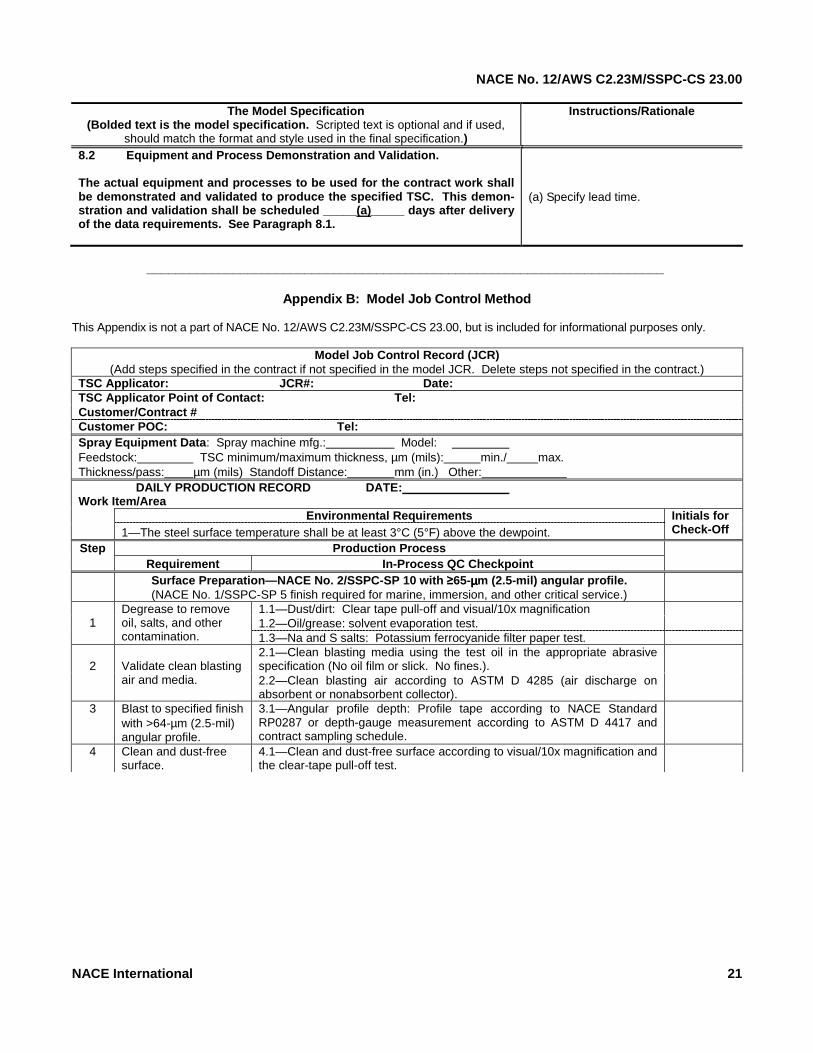
Appendix B: Model Job Control Method This Appendix is not a part of NACE No. 12/AWS C2.23M/SSPC-CS 23.00, but is included for informational purposes only.
Model Job Control Record (JCR) (Add steps specified in the contract if not specified in the model JCR. Delete steps not specified in the contract.)
TSC Applicator: JCR#: Date: TSC Applicator Point of Contact: Tel: Customer/Contract # Customer POC: Tel: Spray Equipment Data: Spray machine mfg.: Model: Feedstock: TSC minimum/maximum thickness, µm (mils): min./ max. Thickness/pass: µm (mils) Standoff Distance: mm (in.) Other: DAILY PRODUCTION RECORD DATE: Work Item/Area
Environmental Requirements 1—The steel surface temperature shall be at least 3°C (5°F) above the dewpoint.
Initials for Check-Off
Production Process Step Requirement In-Process QC Checkpoint
Surface Preparation—NACE No. 2/SSPC-SP 10 with ≥65-µµµµm (2.5-mil) angular profile. (NACE No. 1/SSPC-SP 5 finish required for marine, immersion, and other critical service.)
1.1—Dust/dirt: Clear tape pull-off and visual/10x magnification 1.2—Oil/grease: solvent evaporation test.
1
Degrease to remove oil, salts, and other contamination. 1.3—Na and S salts: Potassium ferrocyanide filter paper test.
2.1—Clean blasting media using the test oil in the appropriate abrasive specification (No oil film or slick. No fines.).
2
Validate clean blasting air and media. 2.2—Clean blasting air according to ASTM D 4285 (air discharge on
absorbent or nonabsorbent collector).
3 Blast to specified finish with >64-µm (2.5-mil) angular profile.
3.1—Angular profile depth: Profile tape according to NACE Standard RP0287 or depth-gauge measurement according to ASTM D 4417 and contract sampling schedule.
4 Clean and dust-free surface.
4.1—Clean and dust-free surface according to visual/10x magnification and the clear-tape pull-off test.

NACE No. 12/AWS C2.23M/SSPC-CS 23.00
22 NACE International
Step Requirement Thermal Spraying Initials for
Check-Off 5.1—Holding periods shall be no more than six hours for steel substrates if there is no flash rusting prior to completion of thermal spraying. See Paragraph 8.2.4.
5.2—In low-humidity environments or in enclosed spaces using industrial dehumidification equipment, a holding period > six hours shall be validated using bend coupons, a portable tensile-bond test, or both according to Paragraph 7.3.2.1 (2).
5
Holding period between completion of surface preparation and completion of thermal spraying.
5.3—Small and movable parts shall be protected if more than 15 minutes is expected to elapse between surface preparation and the start of thermal spraying or if the part is moved to another location.
6.1—A 25- to 50-µm (1.0- to 2.0-mil) flash coat of the TSC may be applied within six hours of completing surface preparation to extend the holding period for up to a further four hours beyond the complete application of the flash rust coat.
6
TSC Flash Coat
6.2—The final TSC thickness shall be applied within four hours of the completion of the application of the flash coat provided the TSC can be maintained free of contamination.
7
Preheating
7.1—For flame spraying, the initial starting area shall be preheated to approximately 120°C (250°F) to prevent water in the flame from condensing on the substrate. Preheating and non-preheating equipment shall be validated using a bend test, tensile-bond measurement, or both.
8.1—The specified coating thickness, (insert value from the specification) in overlapping passes.
Confirm the suitability of the inter-pass thickness with a bend test, tensile-bond measurement, or both.
8
Thermal Spraying
8.2—If rust bloom, blistering, or a degraded coating appears at any time during the application of the TSC, the following process shall be followed:
(a) Stop spraying. (b) Mark off the acceptable sprayed area. (c) Call the TSC inspector to observe and evaluate the error, report the deficiency to the purchaser for remedial action, and record the deficiency and actions taken to resume the job.
Measurements shall be taken according to the contract and recorded in the JCR.
9.1—The TSC shall be measured in accordance with a SSPC-PA 2 Type 2 gauge.
9.2—The average value of five readings for each measurement line or spot shall be determined.
9.3—A measurement line shall be used for flat surfaces. The average value of five readings taken in line at 2.5-cm (1.0-in.) intervals shall be determined. The line measurement measures the peaks and valleys of the TSC.
9
TSC Measurement Schedule
9.4—A measurement spot shall be used for complex geometries and geometry transitions. The measurement spot should be approximately 10 cm2 (1.6 in.2). The spot measurement may not measure the peaks and valleys of the TSC.
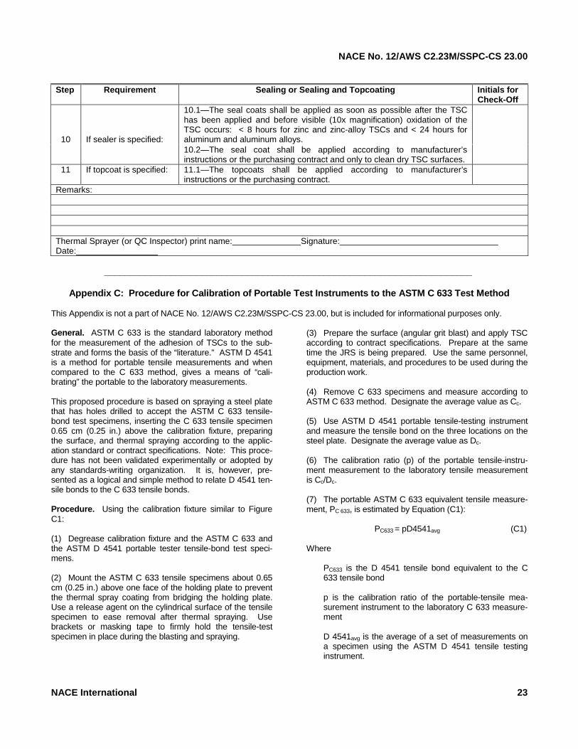
NACE No. 12/AWS C2.23M/SSPC-CS 23.00
Step Requirement Sealing or Sealing and Topcoating Initials for
Check-Off 10.1—The seal coats shall be applied as soon as possible after the TSC has been applied and before visible (10x magnification) oxidation of the TSC occurs: < 8 hours for zinc and zinc-alloy TSCs and < 24 hours for aluminum and aluminum alloys.
10
If sealer is specified:
10.2—The seal coat shall be applied according to manufacturer’s instructions or the purchasing contract and only to clean dry TSC surfaces.
11 If topcoat is specified: 11.1—The topcoats shall be applied according to manufacturer’s instructions or the purchasing contract.
Remarks: Thermal Sprayer (or QC Inspector) print name: Signature: Date:
________________________________________________________________________
Appendix C: Procedure for Calibration of Portable Test Instruments to the ASTM C 633 Test Method This Appendix is not a part of NACE No. 12/AWS C2.23M/SSPC-CS 23.00, but is included for informational purposes only.
General. ASTM C 633 is the standard laboratory method for the measurement of the adhesion of TSCs to the sub-strate and forms the basis of the “literature.” ASTM D 4541 is a method for portable tensile measurements and when compared to the C 633 method, gives a means of “cali-brating” the portable to the laboratory measurements. This proposed procedure is based on spraying a steel plate that has holes drilled to accept the ASTM C 633 tensile-bond test specimens, inserting the C 633 tensile specimen 0.65 cm (0.25 in.) above the calibration fixture, preparing the surface, and thermal spraying according to the applic-ation standard or contract specifications. Note: This proce-dure has not been validated experimentally or adopted by any standards-writing organization. It is, however, pre-sented as a logical and simple method to relate D 4541 ten-sile bonds to the C 633 tensile bonds. Procedure. Using the calibration fixture similar to Figure C1: (1) Degrease calibration fixture and the ASTM C 633 and the ASTM D 4541 portable tester tensile-bond test speci-mens. (2) Mount the ASTM C 633 tensile specimens about 0.65 cm (0.25 in.) above one face of the holding plate to prevent the thermal spray coating from bridging the holding plate. Use a release agent on the cylindrical surface of the tensile specimen to ease removal after thermal spraying. Use brackets or masking tape to firmly hold the tensile-test specimen in place during the blasting and spraying.(3) Prepare the surface (angular grit blast) and apply TSC according to contract specifications. Prepare at the same time the JRS is being prepared. Use the same personnel, equipment, materials, and procedures to be used during the production work. (4) Remove C 633 specimens and measure according to ASTM C 633 method. Designate the average value as Cc. (5) Use ASTM D 4541 portable tensile-testing instrument and measure the tensile bond on the three locations on the steel plate. Designate the average value as Dc. (6) The calibration ratio (p) of the portable tensile-instru-ment measurement to the laboratory tensile measurement is Cc/Dc. (7) The portable ASTM C 633 equivalent tensile measure-ment, PC 633, is estimated by Equation (C1): PC633 = pD4541avg (C1) Where
PC633 is the D 4541 tensile bond equivalent to the C 633 tensile bond p is the calibration ratio of the portable-tensile mea-surement instrument to the laboratory C 633 measure-ment D 4541avg is the average of a set of measurements on a specimen using the ASTM D 4541 tensile testing instrument.
NACE International 23
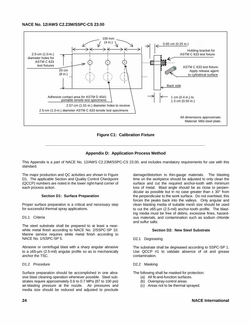
NACE No. 12/AWS C2.23M/SSPC-CS 23.00
Figure C1: Calibration Fixture
All dimensions approximate. Material: Mild steel plate.
1 cm (0.4 in.) to 1.3 cm (0.50 in.)
Back side
ASTM C 633 test fixture: Apply release agent
to cylindrical surface
Adhesive contact area for ASTM D 4541 portable tensile test specimens
2.57-cm (1.01-in.) diameter holes to receive 2.5-cm (1.0-in.) diameter ASTM C 633 tensile test specimens
20 cm (8 in.)
2.5-cm (1.0-in.) diameter holes for
ASTM C 633 test fixtures
100 mm (4 in.)
Holding bracket for ASTM C 633 test fixture
0.65 cm (0.25 in.)
________________________________________________________________________Appendix D: Application Process Method This Appendix is a part of NACE No. 12/AWS C2.23M/SSPC-CS 23.00, and includes mandatory requirements for use with this standard.
The major production and QC activities are shown in Figure D1. The applicable Section and Quality Control Checkpoint (QCCP) numbers are noted in the lower right-hand corner of each process action.
Section D1: Surface Preparation Proper surface preparation is a critical and necessary step for successful thermal spray applications. D1.1 Criteria The steel substrate shall be prepared to at least a near-white metal finish according to NACE No. 2/SSPC-SP 10. Marine service requires white metal finish according to NACE No. 1/SSPC-SP 5. Abrasive or centrifugal blast with a sharp angular abrasive to a ≥65-µm (2.5-mil) angular profile so as to mechanically anchor the TSC. D1.2 Procedure Surface preparation should be accomplished in one abra-sive blast cleaning operation whenever possible. Steel sub-strates require approximately 0.6 to 0.7 MPa (87 to 100 psi) air-blasting pressure at the nozzle. Air pressures and media size should be reduced and adjusted to preclude
damage/distortion to thin-gauge materials. The blasting time on the workpiece should be adjusted to only clean the surface and cut the required anchor-tooth with minimum loss of metal. Blast angle should be as close to perpen-dicular as possible but in no case greater than ± 30° from the perpendicular to the work surface. Do not overblast; this forces the peaks back into the valleys. Only angular and clean blasting media of suitable mesh size should be used to cut the ≥65-µm (2.5-mil) anchor-tooth profile. The blast-ing media must be free of debris, excessive fines, hazard-ous materials, and contamination such as sodium chloride and sulfur salts.
Section D2: New Steel Substrate D2.1 Degreasing The substrate shall be degreased according to SSPC-SP 1. Use QCCP #1 to validate absence of oil and grease contamination. D2.2 Masking The following shall be masked for protection:
(a) All fit-and-function surfaces. (b) Overspray-control areas. (c) Areas not to be thermal sprayed.
24 NACE International

NACE No. 12/AWS C2.23M/SSPC-CS 23.00
Figure D1: Key Production and Quality Control Checkpoints (QCCPs) for Applying Thermal Spray Coatings
CONTAMINATION
MASKING
CLEAN AIR
BLAST MEDIA QUALITY
NEAR-WHITE FINISH AND PROFILE
QCCP #5
SPRAY PARAMETERS
QCCP #6
BEND TEST
QCCP #7
SUBSTRATE TEMP. ≥ 5° ABOVE DEWPOINT QCCP #7.1
120°C (250°F) PREHEAT FOR FLAME SPRAYING QCCP #7.2A
SPRAY NORMAL ±30° TO SURFACE AND AT THE SPECIFIED STANDOFF
QCCP #7.2B
NO RUST BLOOM OR DEGRADED TSC QCCP #7.2C and D
TOTAL TSC THICKNESS PER SAMPLING SCHEDULE QCCP #7.4
TSC CUT TEST IF > SPECIFIED THICKNESS QCCP #7.8
SEALER APPLICATION
QCCP #8
TOPCOAT APPLICATION
QCCP #9
Sections Section D.5
Section D.6 Section
D.7 THERMAL
SPRAY EQUIPMENT
SETUP
QCCP #1: Oil and Grease
Inspect for the absence of oil and grease contamination by the following: 1.1 Visual inspection during removal of oil/grease conta-mination. Continue degreasing until all visible signs of contamination are removed. 1.2 Conduct the UV-light test, the qualitative-solvent evaporation test, or the heat test.
(a) Use a UV lamp to confirm the absence of oil or grease contamination. (b) Conduct a solvent evaporation test by applying several drops or a small splash of a residue-free sol-vent such as trichloromethane on the areas suspect-ed of oil and grease retention (e.g., pitting and crev-ice-corrosion areas, depressed areas, especially those collecting contamination, etc.). An evapora-tion ring forms if oil or grease contamination is pres-ent. (c) Conduct a heat test by using a torch to heat the degreased metal to about 110°C (225°F). Residual oil/grease contamination is drawn to the metal sur-face and is visually apparent.
1.3 Continue inspection and degreasing until the test is passed.
The fit-and-function areas must be protected from the blast cleaning, thermal spraying, and sealing or sealing and top-coating operations. Overspray-control areas have complex geometry where overspray cannot be eliminated. Use QCCP #2 to validate masking suitability.
QCCP #2: Masking 2.1 All fit-and-function surfaces and those other sur-faces and areas specified by the purchaser not to be abrasive blasted or to be thermal sprayed shall be visu-ally inspected. 2.2 Covers and masking shall be inspected to ensure they are attached securely to survive the blasting and thermal spraying operations. 2.3 Complex geometries (e.g., pipe flanges, intersec-tions of structural beams, and valve manifolds) shall be masked to eliminate or minimize overspray. Overspray is that TSC applied outside the authorized parameters, primarily the gun-to-substrate standoff distance and spray angle (perpendicular ±30°). 2.4 Potential overspray surfaces should be protected with clean, metal masks or clean, removable masking materials to prevent overspray from depositing on sur-faces not already sprayed to the specified parameters.
NACE International 25
NACE No. 12/AWS C2.23M/SSPC-CS 23.00
D2.3 Blast Equipment The TSC applicator shall use mechanical (centrifugal wheel) and/or pressure-pot blast-cleaning equipment and proce-dures. Suction-blasting equipment shall not be used. QCCP #3 shall be used to validate clean and dry air.QCCP #3: Clean and Dry Air When pressure-pot blast cleaning is used, the air used for final anchor-tooth blasting and brush blasting or blow-down prior to thermal spraying shall be clean and dry and without moisture and oil. The compressed air shall be checked for oil and water contamination per ASTM D 4285: 3.1 Slightly open a valve downstream from the filter or dryer. Allow the air to vent with a slightly audible flow into an open, dry container for one minute. Any wetting or staining indicates contamination. 3.2 If moisture or contamination is detected, correct any deficiency before going further. 3.3 Repeat step 3.1 above, but place a clean, white cloth over the valve outlet. Any wetting or staining indi-cates contamination.
D2.4 Surface Finish and Profile The surface shall be blast cleaned to NACE No. 1/SSPC-SP 5 for marine and immersion service or to at least NACE No. 2/SSPC-SP 10 for other service both with a ≥65-µm (2.5-mil) sharp angular profile. The substrate should be thick enough to preclude damage to the workpiece or defor-mation from the abrasive blasting. QCCP #4 shall be used to validate clean-blasting media. QCCP #5 shall be used to validate metal finish and profile depth.
Section D3: Contaminated Steel Substrate Steel contaminated with deicing salts, oil, grease, bird drop-pings, etc., and corroded and pitted steel requires more intensive surface preparation than new steel. To produce the minimum required near-white metal finish with a ≥65-µm (2.5-mil) profile, the surface preparation schedule should be tailored for the specific steel surfaces to be cleaned. High-pressure water cleaning, heat cleaning, chemical washing (followed by water flushing), steam cleaning, and abrasive-blast cleaning, singly and in combination, may be required to clean contaminated steel. D3.1 Degreasing The surface shall be degreased as required according to contract specifications (e.g., hydroblast, steam clean, sol-vent wash, or detergent wash).
QCCP #4: Clean Blasting Media Prior to the use of the abrasive-blasting media for final anchor-tooth blasting or brush blasting: 4.1 The blasting media shall be visually inspected for the absence of contamination and debris using 10x mag-nification. 4.2 Inspection for the absence of oil contamination shall be conducted using the test for oil in the appropriate abrasive specification (no oil film or slick) and/or the fol-lowing procedure: (1) Fill a small, clean 100- to 200-mL (4- to 6-oz) bottle half-full of abrasive particles. (2) Fill the remainder of the bottle with potable water. (3) Cap and shake the bottle. (4) Inspect water for oil film/slick. If any oil film/slick is observed, do not use the blasting media. (5) Clean blasting equipment, especially the pot and hoses, then replace blasting media and retest.
QCCP #5: Near-White Finish and Anchor-Tooth
Profile 5.1 Using SSPC-VIS 1, the surface shall be visually inspected for conformance with NACE No. 2/SSPC-SP 10 or NACE No. 1/SSPC-SP 5 if specified in the contract. The clear-cellophane-tape test shall be used to confirm absence of dust as required. The frequency of use of the cellophane tape test shall be determined by the specifier. 5.2 The anchor-tooth profile shall be measured with pro-file tape (NACE Standard RP0287) or a depth-gauge micrometer. At least one measurement shall be taken every 10 to 20 m2 (100 to 200 ft2) or as otherwise speci-fied by the purchaser. 5.3 If the profile is <65 µm (2.5 mils) blasting shall conti-nue until a ≥65-µm (2.5-mil) profile is obtained. 5.4 Information shall be recorded on sketches or draw-ings or as required by the purchasing contract.
D3.2 Thermal Cleaning
SAFETY AND PROCEDURE PRECAUTION: This proce-dure shall be used only if there is no danger of an explosion or fire and no degradation of the metal temper. Temper-atures shall not exceed 300°C (570°F) on steel alloys.
(1) The contamination shall be baked out or burned off (the dark brown or black surface areas) in an oven or with a rosebud torch. The substrate temperature shall be kept between 250 and 300°C (480 and 570°F) for the time nec-essary to bake out or burn off the oil and grease contamin-ation.
26 NACE International
NACE No. 12/AWS C2.23M/SSPC-CS 23.00
(2) The substrate area to be thermal sprayed within the next six hours or longer according to Paragraph D4.2 shall be blasted to a minimum near-white metal finish with >65 µm (2.5 mils) anchor-tooth. (3) Repeat steps (1) and (2) above as required until the thermal spray job is completed. D3.3 Removal of Soluble Salts: If required by owner specifications, the surface should be tested for the presence of soluble salts. Methods for testing are described in SSPC-TU 4. The acceptable levels and methods of removal of soluble salts shall be determined by the specifier. D3.4 Rust Bloom The thermal spray coating shall be applied within six hours after blast cleaning. If rust bloom (i.e., the visual appear-ance of rust on the blast-cleaned surface) appears on the blasted surface before thermal spraying, the rust bloom shall be removed and the TSC applicator shall wait 24 hours to observe for any recurrence before spraying. Under very dry conditions, a longer waiting period may be neces-sary.
D3.4.1 Light Rust Bloom If there is light rust bloom (light in color and greater than 10% of the surface area), the substrate area that will be thermal sprayed within the next six hours shall be reblasted to achieve the specified level of cleanli-ness. D3.4.2 Heavy Rust Bloom If there is heavy rust bloom (dark brown or black color), other cleaning methods shall be continued (e.g., wet-abrasive, high- and ultra high-pressure water, or ther-mal cleaning singly or in combination) to remove the contamination.
Section D4: Post-Blasting Substrate Condition and Thermal Spraying Period
D4.1 Steel Surface Temperature and Cleanliness The steel surface temperature shall be at least 3°C (5°F) above the dewpoint. The surface shall be cleaned to NACE No. 2/SSPC-SP 10 finish as a minimum. D4.2 Holding Period (1) The TSC shall always be applied to white metal NACE No. 1/SSPC-SP 5 or near-white metal finish (NACE No. 2/SSPC-SP 10), free of visible and invisible contaminants. It is common practice in field work to apply the TSC during the same work shift as the final blast cleaning is preformed. The logical end point of the holding period is when the sur-
face cleanliness degrades or a change in performance (bend or tensile test) occurs. (2) As a general guide, however, the time between the completion of the final anchor-tooth blasting (or final brush blasting) and the completion of the thermal spraying shall be no greater than about six hours for steel substrates. In high-humidity and damp environments, shorter holding per-iods shall be used. If rust bloom or a degraded coating appears at any time while spraying, Paragraph D4.2 (6), shall be strictly observed. (3) In low-humidity environments or in controlled environ-ments with enclosed structures using industrial dehumidifi-cation equipment, it may be possible to retard the oxidation of the steel and hold the near-white metal finish for more than six hours. The TSC applicator, with the concurrence of the purchaser, can validate a holding period greater than six hours by determining the acceptable temperature-humidity envelope for the work enclosure by spraying and analyzing bend coupons, tensile-bond coupons, or both. (4) If specified by the purchasing contract, a flash coat of TSC equal to or greater than 25 µm (1.0 mil) may be applied within six hours of completing the surface prepara-tion to extend the holding period for up to four hours beyond the complete application of the flash coat. The final TSC thickness, however, shall be applied within four hours of the completion of the application of the flash coat. This proce-dure shall be validated with a tensile-bond measurement, bend test, or both, by spraying a flash coat and waiting the delay period before applying the final coating thickness. (5) For small and movable parts, if more than 15 minutes is expected to elapse between the surface preparation and the start of thermal spraying, or if the part is moved to ano-ther location, the prepared surface should be protected from moisture, contamination, and finger/hand marks. Wrapping with clean print-free paper is normally adequate. (6) If rust bloom, blistering, or degraded coating appears at any time during the application of the TSC, the following procedure applies:
(a) Stop spraying. (b) Mark off the satisfactorily sprayed area. (c) Repair the unsatisfactory TSC (i.e., remove degraded TSC and re-establish the minimum near-white metal finish and anchor-tooth profile depth). (d) Record the actions taken to resume the job in the JCR. (e) Call the TSC inspector to observe and report the remedial action to the purchaser.
Section D5: Thermal Equipment Set-Up and Spraying Sequence
D5.1 Thermal Spray Equipment Set-Up (1) Thermal spray equipment shall be set up, calibrated, and operated according to the manufacturer’s instructions
NACE International 27
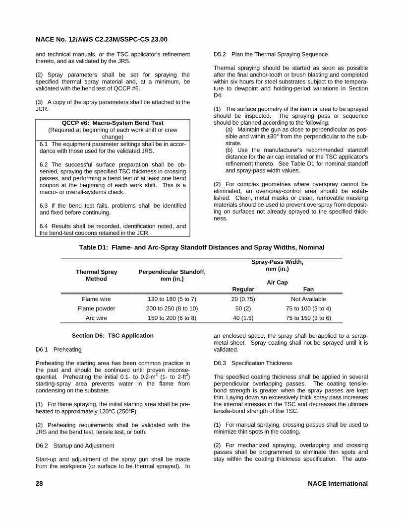
NACE No. 12/AWS C2.23M/SSPC-CS 23.00
and technical manuals, or the TSC applicator’s refinement thereto, and as validated by the JRS. (2) Spray parameters shall be set for spraying the specified thermal spray material and, at a minimum, be validated with the bend test of QCCP #6. (3) A copy of the spray parameters shall be attached to the JCR.
QCCP #6: Macro-System Bend Test (Required at beginning of each work shift or crew
change) 6.1 The equipment parameter settings shall be in accor-dance with those used for the validated JRS. 6.2 The successful surface preparation shall be ob-served, spraying the specified TSC thickness in crossing passes, and performing a bend test of at least one bend coupon at the beginning of each work shift. This is a macro- or overall-systems check. 6.3 If the bend test fails, problems shall be identified and fixed before continuing. 6.4 Results shall be recorded, identification noted, and the bend-test coupons retained in the JCR.
D5.2 Plan the Thermal Spraying Sequence Thermal spraying should be started as soon as possible after the final anchor-tooth or brush blasting and completed within six hours for steel substrates subject to the tempera-ture to dewpoint and holding-period variations in Section D4. (1) The surface geometry of the item or area to be sprayed should be inspected. The spraying pass or sequence should be planned according to the following:
(a) Maintain the gun as close to perpendicular as pos-sible and within ±30° from the perpendicular to the sub-strate. (b) Use the manufacturer’s recommended standoff distance for the air cap installed or the TSC applicator’s refinement thereto. See Table D1 for nominal standoff and spray-pass width values.
(2) For complex geometries where overspray cannot be eliminated, an overspray-control area should be estab-lished. Clean, metal masks or clean, removable masking materials should be used to prevent overspray from deposit-ing on surfaces not already sprayed to the specified thick-ness.
Table D1: Flame- and Arc-Spray Standoff Distances and Spray Widths, Nominal
Spray-Pass Width,
mm (in.)
Air Cap
Thermal Spray Method
Perpendicular Standoff, mm (in.)
Regular Fan
Flame wire 130 to 180 (5 to 7) 20 (0.75) Not Available
Flame powder 200 to 250 (8 to 10) 50 (2) 75 to 100 (3 to 4)
Arc wire 150 to 200 (6 to 8) 40 (1.5) 75 to 150 (3 to 6)
Section D6: TSC Application
D6.1 Preheating Preheating the starting area has been common practice in the past and should be continued until proven inconse-quential. Preheating the initial 0.1- to 0.2-m2 (1- to 2-ft2) starting-spray area prevents water in the flame from condensing on the substrate. (1) For flame spraying, the initial starting area shall be pre-heated to approximately 120°C (250°F). (2) Preheating requirements shall be validated with the JRS and the bend test, tensile test, or both. D6.2 Startup and Adjustment Start-up and adjustment of the spray gun shall be made from the workpiece (or surface to be thermal sprayed). In
an enclosed space, the spray shall be applied to a scrap-metal sheet. Spray coating shall not be sprayed until it is validated. D6.3 Specification Thickness The specified coating thickness shall be applied in several perpendicular overlapping passes. The coating tensile-bond strength is greater when the spray passes are kept thin. Laying down an excessively thick spray pass increases the internal stresses in the TSC and decreases the ultimate tensile-bond strength of the TSC. (1) For manual spraying, crossing passes shall be used to minimize thin spots in the coating. (2) For mechanized spraying, overlapping and crossing passes shall be programmed to eliminate thin spots and stay within the coating thickness specification. The auto-
28 NACE International
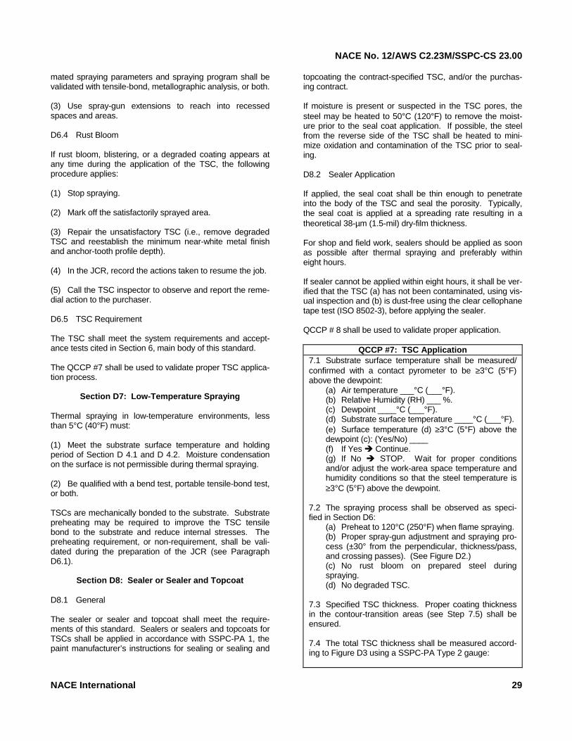
NACE No. 12/AWS C2.23M/SSPC-CS 23.00
mated spraying parameters and spraying program shall be validated with tensile-bond, metallographic analysis, or both. (3) Use spray-gun extensions to reach into recessed spaces and areas. D6.4 Rust Bloom If rust bloom, blistering, or a degraded coating appears at any time during the application of the TSC, the following procedure applies: (1) Stop spraying. (2) Mark off the satisfactorily sprayed area. (3) Repair the unsatisfactory TSC (i.e., remove degraded TSC and reestablish the minimum near-white metal finish and anchor-tooth profile depth). (4) In the JCR, record the actions taken to resume the job. (5) Call the TSC inspector to observe and report the reme-dial action to the purchaser. D6.5 TSC Requirement The TSC shall meet the system requirements and accept-ance tests cited in Section 6, main body of this standard. The QCCP #7 shall be used to validate proper TSC applica-tion process.
Section D7: Low-Temperature Spraying Thermal spraying in low-temperature environments, less than 5°C (40°F) must: (1) Meet the substrate surface temperature and holding period of Section D 4.1 and D 4.2. Moisture condensation on the surface is not permissible during thermal spraying. (2) Be qualified with a bend test, portable tensile-bond test, or both. TSCs are mechanically bonded to the substrate. Substrate preheating may be required to improve the TSC tensile bond to the substrate and reduce internal stresses. The preheating requirement, or non-requirement, shall be vali-dated during the preparation of the JCR (see Paragraph D6.1).
Section D8: Sealer or Sealer and Topcoat D8.1 General The sealer or sealer and topcoat shall meet the require-ments of this standard. Sealers or sealers and topcoats for TSCs shall be applied in accordance with SSPC-PA 1, the paint manufacturer’s instructions for sealing or sealing and
topcoating the contract-specified TSC, and/or the purchas-ing contract. If moisture is present or suspected in the TSC pores, the steel may be heated to 50°C (120°F) to remove the moist-ure prior to the seal coat application. If possible, the steel from the reverse side of the TSC shall be heated to mini-mize oxidation and contamination of the TSC prior to seal-ing. D8.2 Sealer Application If applied, the seal coat shall be thin enough to penetrate into the body of the TSC and seal the porosity. Typically, the seal coat is applied at a spreading rate resulting in a theoretical 38-µm (1.5-mil) dry-film thickness. For shop and field work, sealers should be applied as soon as possible after thermal spraying and preferably within eight hours. If sealer cannot be applied within eight hours, it shall be ver-ified that the TSC (a) has not been contaminated, using vis-ual inspection and (b) is dust-free using the clear cellophane tape test (ISO 8502-3), before applying the sealer. QCCP # 8 shall be used to validate proper application.
QCCP #7: TSC Application 7.1 Substrate surface temperature shall be measured/ confirmed with a contact pyrometer to be ≥3°C (5°F) above the dewpoint:
(a) Air temperature ___°C (___°F). (b) Relative Humidity (RH) ___ %. (c) Dewpoint ____°C (___°F). (d) Substrate surface temperature ____°C (___°F). (e) Surface temperature (d) ≥3°C (5°F) above the dewpoint (c): (Yes/No) ____ (f) If Yes ! Continue. (g) If No ! STOP. Wait for proper conditions and/or adjust the work-area space temperature and humidity conditions so that the steel temperature is ≥3°C (5°F) above the dewpoint.
7.2 The spraying process shall be observed as speci-fied in Section D6:
(a) Preheat to 120°C (250°F) when flame spraying. (b) Proper spray-gun adjustment and spraying pro-cess (±30° from the perpendicular, thickness/pass, and crossing passes). (See Figure D2.) (c) No rust bloom on prepared steel during spraying. (d) No degraded TSC.
7.3 Specified TSC thickness. Proper coating thickness in the contour-transition areas (see Step 7.5) shall be ensured. 7.4 The total TSC thickness shall be measured accord-ing to Figure D3 using a SSPC-PA Type 2 gauge:
NACE International 29
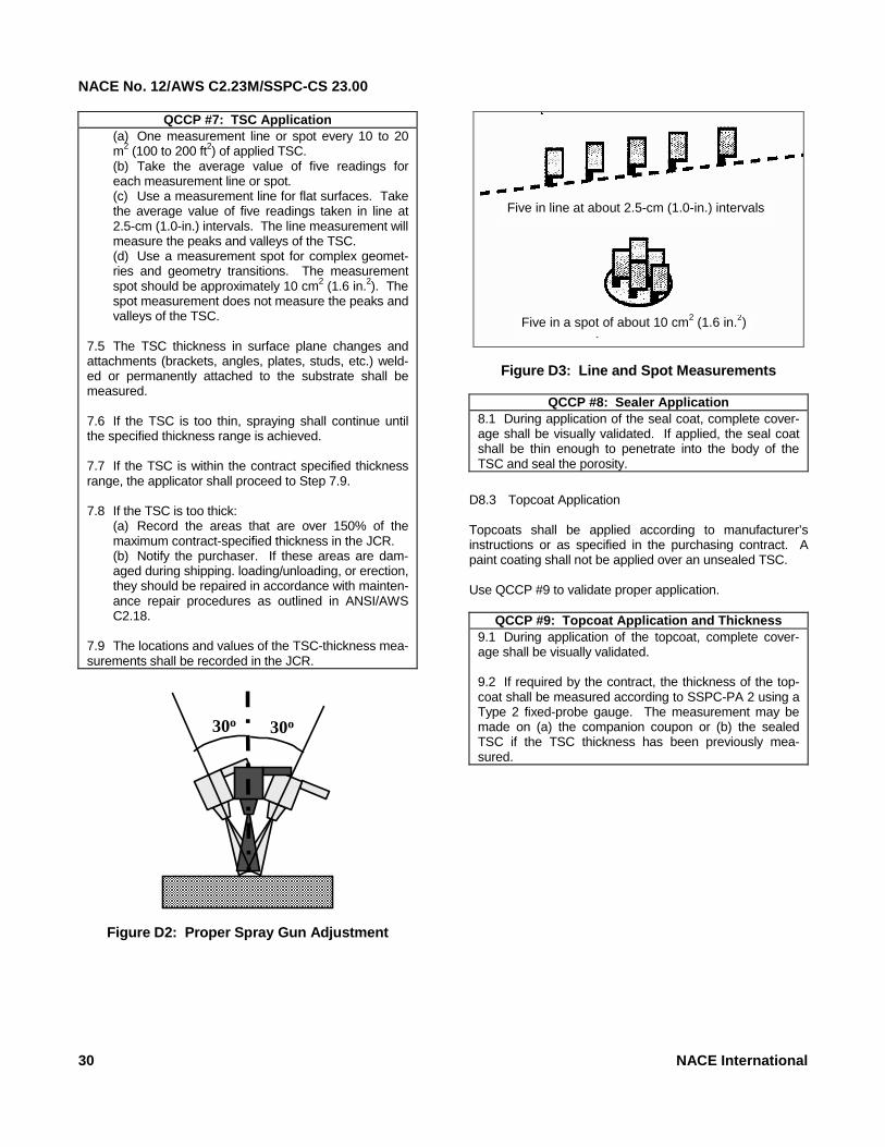
NACE No. 12/AWS C2.23M/SSPC-CS 23.00
QCCP #7: TSC Application (a) One measurement line or spot every 10 to 20 m2 (100 to 200 ft2) of applied TSC. (b) Take the average value of five readings for each measurement line or spot. (c) Use a measurement line for flat surfaces. Take the average value of five readings taken in line at 2.5-cm (1.0-in.) intervals. The line measurement will measure the peaks and valleys of the TSC. (d) Use a measurement spot for complex geomet-ries and geometry transitions. The measurement spot should be approximately 10 cm2 (1.6 in.2). The spot measurement does not measure the peaks and valleys of the TSC.
7.5 The TSC thickness in surface plane changes and attachments (brackets, angles, plates, studs, etc.) weld-ed or permanently attached to the substrate shall be measured. 7.6 If the TSC is too thin, spraying shall continue until the specified thickness range is achieved. 7.7 If the TSC is within the contract specified thickness range, the applicator shall proceed to Step 7.9. 7.8 If the TSC is too thick:
(a) Record the areas that are over 150% of the maximum contract-specified thickness in the JCR. (b) Notify the purchaser. If these areas are dam-aged during shipping. loading/unloading, or erection, they should be repaired in accordance with mainten-ance repair procedures as outlined in ANSI/AWS C2.18.
7.9 The locations and values of the TSC-thickness mea-surements shall be recorded in the JCR.
30o 30o
Figure D2: Proper Spray Gun Adjustment
Figure D3: Line and Spot Measurements
QCCP #8: Sealer Application 8.1 During application of the seal coat, complete cover-age shall be visually validated. If applied, the seal coat shall be thin enough to penetrate into the body of the TSC and seal the porosity.
D8.3 Topcoat Application Topcoats shall be applied according to manufacturer’s instructions or as specified in the purchasing contract. A paint coating shall not be applied over an unsealed TSC. Use QCCP #9 to validate proper application.
QCCP #9: Topcoat Application and Thickness 9.1 During application of the topcoat, complete cover-age shall be visually validated. 9.2 If required by the contract, the thickness of the top-coat shall be measured according to SSPC-PA 2 using a Type 2 fixed-probe gauge. The measurement may be made on (a) the companion coupon or (b) the sealed TSC if the TSC thickness has been previously mea-sured.
Five in line at about 2.5-cm (1.0-in.) intervals
Five in a spot of about 10 cm2 (1.6 in.2)
30 NACE International