Embed Size (px)
Citation preview

1
NACE Paper No.
MECCFEB16-7995
Mitigation of Soil-Side Corrosion on Storage Tank Bottoms in the Absence or Deficient of CP System
Dr. A. Meroufel
Desalination Technologies Research
Institute (DTRI) P.O. Box 8328 Jubail 31951
Kingdom of Saudi Arabia
K. Abed
Cortec Middle-East P.O. Box 115133 Dubai,
United Arab Emirates
M. Al-Hajri
Desalination Technologies Research
Institute (DTRI)
P.O. Box 8328 Jubail 31951
Kingdom of Saudi Arabia
ABSTRACT Protection of aboveground water storage tank bottom plates against soil side corrosion is an important concern for the desalination industry, particularly when considering continuous operation requirements for these assets. Effective corrosion control measures must be taken to ensure bottom plate integrity for continuous, safe, and economical operation of storage tanks. One of the most commonly used corrosion protection methods is a cathodic protection (CP) system. However, it is well accepted that CP alone may not be enough to achieve the required level of protection. A promising industrial practice is to introduce volatile corrosion inhibitors (VCI) materials under tank bottoms to either supplement existing CP systems or provide protection in its absence. This work aims to determine the effectiveness of introducing an amine carboxylate based VCI slurry to protect water storage tank bottoms against soil side corrosion while in service. The subject water tank was constructed on a sweet sand pad with an inactive CP system. VCI slurry efficiency was determined through corrosion rate monitoring using electrical resistance (ER) probes. Corrosion rate monitored over 200 days indicated an average 92% reduction in the metal loss rate. At the end of the test period, selected exposed probe element was subjected to visual inspection, spectroscopic and structural analysis to explore the passivation effect of VCI and correlate the results with ER readings. Key words: aboveground storage tank, AST, volatile corrosion inhibitor, VCI, cathodic protection, electrical resistance, passivity, online injection, in service tanks.
INTRODUCTION Storing liquids such as potable water, process chemicals, and heavy fuel oil in aboveground storage tanks (AST) is an important task at desalination plants. AST durability is assured by solid specifications for the construction phase and can be improved through good operation and maintenance practices.
2
American Petroleum Institute (API) Standards 650, 651, 652, 653, and 620 are the primary industry standards by which most AST are designed, constructed, and maintained. For two decades, the saline water conversion corporation (SWCC1) has constructed AST with different dimensions and purposes as per API 650. However, due to tightly planned testing and inspection schedules to ensure the continuous supply of potable water, it has always been challenging for SWCC to follow API recommendations for inspection and maintenance. Table 1 summarizes some of the soil-side bottom plate failures recorded on different tanks in SWCC facilities.
Table 1
Record of AST bottom plates failures within desalination plants
Stored Liquid
Construction Year
Failure Year
Failure Mode
Product Water 1982 2004 GC + PC
Product Water 1998 2005 GC + PC
HFO 1988 2002 PC
Product Water 1988 2005 PC
GC: General Corrosion; PC: Pitting Corrosion; HFO: Heavy Fuel Oil
In API 650, there are no stated requirements for corrosion allowance; that decision is left to the owner.1 Therefore, online corrosion monitoring becomes necessary to achieve the continuous, safe, and economical operation of the storage tank. Many online corrosion monitoring techniques are available with their own advantages and limitations.2 For example, electrical resistance (ER) probes were adopted in the United States for fuel tanks constructed on inhibited sand as a cost-effective alternative to retrofitting existing CP systems.3 However, a very limited number of solutions, if any, are available for operators to intervene and control soil-side corrosion of tank bottom plates without putting the tank out-of service. This paper demonstrates the concept of using an amine carboxylate based VCI slurry, coupled with ER corrosion probes, as an online soil-side corrosion control method for in-service water storage tanks.
MITIGATION OF SOIL-SIDE CORROSION OF STORAGE TANK BOTTOM PLATES
Different methods, as standalone or in combination, have been adopted to control soil-side corrosion of bottom plates such as proper foundation design, placement of special backfills, construction using corrosion resistant alloys, coatings, and CP systems. Each one of these methods has its own performance and limitations; some of them are briefly discussed hereunder.
1 National company operating and maintaining desalination plants in the kingdom of Saudi Arabia

3
Cathodic protection to underside of tank bottom plates can be provided by sacrificial galvanic anodes or by an impressed current cathodic protection (ICCP) system. The use of galvanic anodes is limited to small tank diameters and for soil resistivity of 5000 Ω.cm or less. When more current or longer design life is required, ICCP is preferred.4 However, in both systems, electrical current flow between the anode and the cathode should be maintained to provide adequate protection. For instance, the presence of aggregates was found to cause a CP deficiency by preventing a uniform CP current flow, leading to severe corrosion.5 The same finding was observed in the case of an oily sand pad where its high electrical resistivity shielded CP current flow and affected uniform distribution throughout the tank floor plate surface.6 Moreover, filling and refilling of the storage tank and weld overlaps created air gaps between the tank bottom plates and the tank foundation, which consequently prevented the CP current from reaching to the bottom plates in these areas. In 2012, a survey carried out at an oil and gas facility in the Arabian Peninsula on randomly selected tanks showed that soil-side corrosion was present on all CP protected and non-CP protected tanks. It also showed that air gaps between bottom plates and foundations were detected in all tanks and that the measured CP potential during the annual CP survey was not representative of the bottom plate condition.7 In addition to an ICCP system, the use of protective coatings on the soil-side of tank bottom plates is often considered. However, these are always prone to pin holes defects during application and damage during installation and at weld joints. They are also subject to inevitable ageing process over time, leading to delamination and under coating corrosion. Due to the wide variety of soil conditions and tank hydrostatic pressures, different construction pads have been considered such as continuous asphalt, concrete, oily sand, and washed sand. Due to ageing, all these foundations provide limited degree of protection and remain susceptible to ingress of corrosion species from soil such as moisture, chlorides, and microorganisms.8 The use of double bottom design with containment high density polyethylene (HDPE) liner is one of the practices where the use of CP is necessary and anodes should be installed between the upper and lower floor or containment liner. For this type of design, CP is problematical to maintain or repair.9
VOLATILE CORROSION INHIBITORS (VCI) FOR AST BOTTOM PLATES PROTECTION.
A volatile corrosion inhibitor is a chemical substance that acts to reduce soil-side corrosion by a combination of volatilization from the VCI media, vapor transport in the headspace between floor plates and the tank pad atmosphere, and adsorption onto surfaces in the space. The inhibition mechanism involved includes adsorption, dissociation, and hydrophobic effects on metal surfaces, where the rate of soil-side corrosion of bottom plate surfaces is thereby inhibited. VCI chemistry comes in different forms to fit different application methods in protecting AST bottom plates. It comes in powder form and can be delivered by fogging application through the tank floor while it is out of service. VCI chemistry is also available as a thin solid-liquid solution that can be delivered into the interstitial spaces under the tank floor through injection pipes placed in the sand layer while the tank is in service.9 During tank construction, VCI powder enclosed in in a pouch constructed from a breathable membrane can be placed immediately on top of HDPE liner. This breathable pouch allows the VCI molecules to be emitted through the membrane, diffuse though the sand layer, and form a molecular layer on tank bottom plates providing soil-side corrosion protection during and after construction of the tank.

4
The utilization of organic based VCI in the protection of AST bottoms against soil-side corrosion started in 1986.10 Rials et al.11 published in 1993 a technical paper discussing the use and effectiveness of VCI to control soil-side corrosion of aboveground storage tanks with secondary containment, such as double bottom tanks. The study suggested that VCI is effective in controlling corrosion in moisture-saturated conditions, especially pitting corrosion when compared to an ICCP system. Gandhi discussed research and fieldwork that indicated VCI can protect bottoms of storage tanks over 15 years and can be used in conjunction with the traditional CP corrosion control methods.12 Expected service life of the initial corrosion inhibitor installation depends on the dosage rate, delivery method, distribution, and enclosure of the inhibitor. In the Middle-East, the first published recommendations to use VCI for underside AST bottom corrosion was in 2010 initiated by Yu 6 and in 2012 by Barnawi.7 In 2013, whited et al.13 discussed a successful pilot project on the use of VCI in protecting a very large 107.4 meter diameter crude oil storage AST, with oily sand pad, located at a tank farm in the eastern Arabian Peninsula. The effectiveness of VCI against soil-side corrosion is generally demonstrated through the online monitoring of corrosion rate with and without VCI by using ER probes installed in the under tank environment. On this basis, ER probes can be used to indicate the need for future VCI replenishment. Since the sensing element of the ER probe is usually made of an alloy with the same grade as the tank bottom plate, it is believed that the data obtained from these probes are more representative of AST bottom plate corrosion than the bottom plate potential using reference electrodes, which, can suffer from ohmic drop causing readings errors.
EXPERIMENTAL PROCEDURE The objective of the present study was to explore the effectiveness of online injection of an amine carboxylate based VCI slurry to protect against soil-side corrosion in absence of a CP system and highlight some of the practical factors that control VCI performance. The VCI material used in this study was Cortec® Corrologic® Slurry. A 15 m diameter AST with capacity of 946 m and bottom plates made from carbon steel St.35 was selected to carry out the study. The tank was initially a firewater tank constructed in 1980 on a sweet sand pad with a CP system with concrete ring wall. However, the tank does not have an HDPE liner or an active CP system. Unfortunately, no inspection or record data was available.
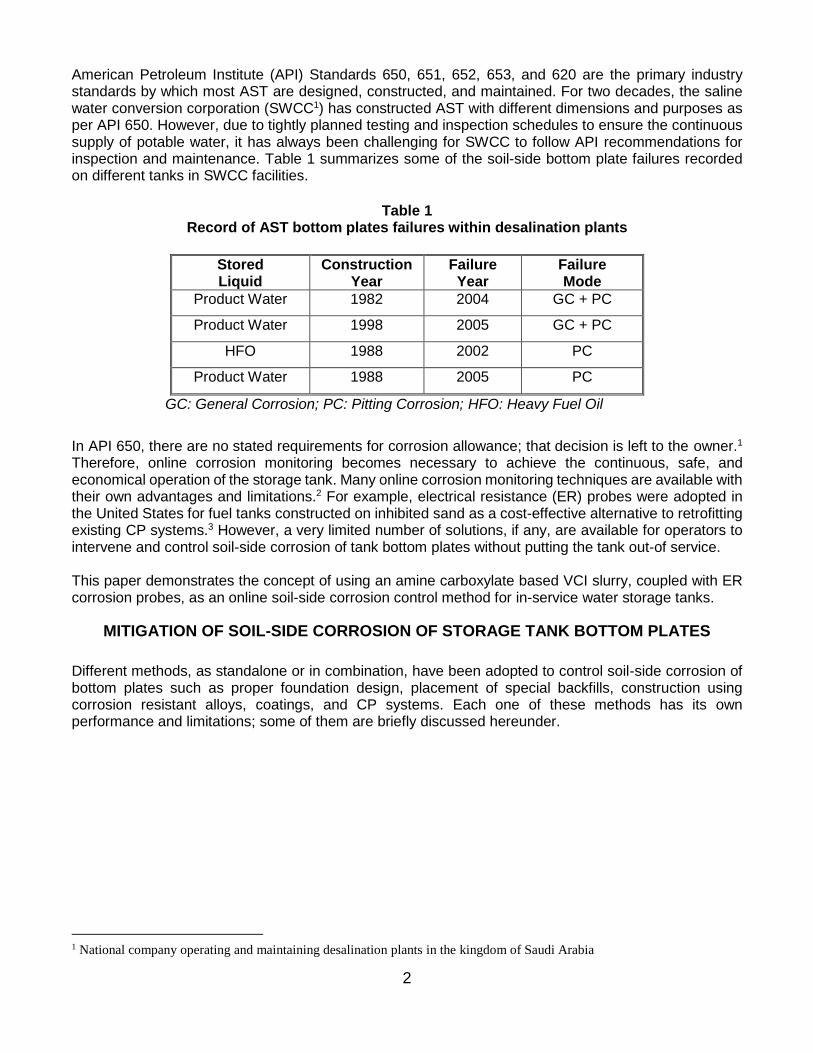
The online injection system proposed for this tank as shown in figures 1 and 2. The general description
of the system is as follows:
1. Three VCI injection tubes (continuous arrows in Figure 1) were installed by core drilling into the
concrete ring wall.
2. A corrosion rate monitoring system using cylindrical ER probes (discontinuous arrows in Figure 1)
was installed to monitor the corrosiveness of the under tank environment.
3. A seal system was installed to close any gaps between the annular plate and concrete ring wall.
5
Figure 1: Top View of the AST with locations of ER probes and injection points.
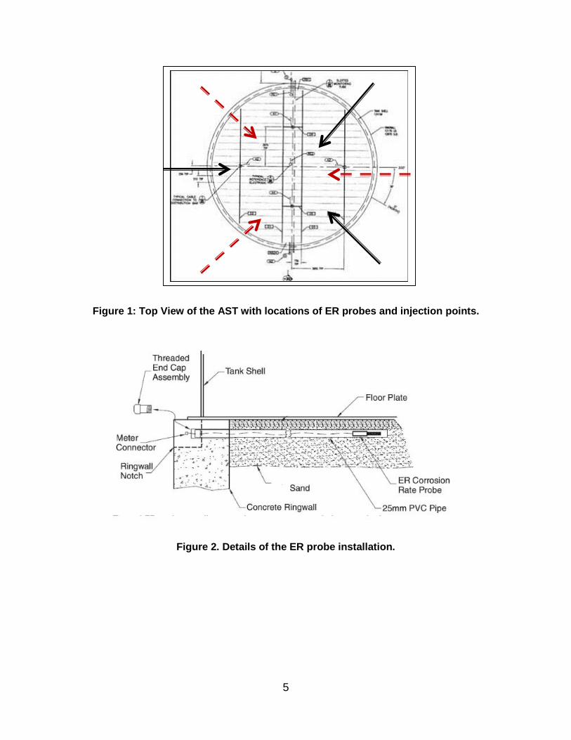
Figure 2. Details of the ER probe installation.

6
The soil under of the tank was analyzed for different parameters (Table 2)
Table 2
Under tank Soil analysis
Parameter Value Method
Moisture (%) 1-1.1 Gravimetric
pH 7.5-7.9 EA(2) 9045D
Density (g.cm-3) 2.65 ASTM D854
Chlorides concentration (ppm) 830-1700 Titration
Sulfates Concentration (ppm) 2700-3700 Titration
Composition 89% Sand 9% Silt 2% Clay
ASTM D422-07
RESULTS
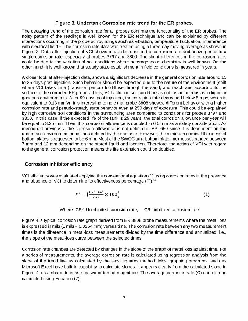
Corrosion rate monitoring. Corrosion monitoring was carried out using ER technique in the absence and presence of slurry carrying an amine carboxylate VCI. Figure 3 shows the three-day moving average corrosion rate data for the three probes during the whole project duration of 380 days.
(2) Environment Agency, PO Box 544 Rotherham S60 1BY
Without VCI With VCI
7
Figure 3. Undertank Corrosion rate trend for the ER probes.
The decaying trend of the corrosion rate for all probes confirms the functionality of the ER probes. The noisy pattern of the readings is well known for the ER technique and can be explained by different interactions occurring in the probe surroundings such as vibration, temperature fluctuation, interference with electrical field.14 The corrosion rate data was treated using a three-day moving average as shown in Figure 3. Data after injection of VCI shows a fast decrease in the corrosion rate and convergence to a single corrosion rate, especially at probes 3797 and 3800. The slight differences in the corrosion rates could be due to the variation of soil conditions where heterogeneous chemistry is well known. On the other hand, it is well known that steady state establishment in field conditions is measured in years. A closer look at after-injection data, shows a significant decrease in the general corrosion rate around 15 to 25 days post injection. Such behavior should be expected due to the nature of the environment (soil) where VCI takes time (transition period) to diffuse through the sand, and reach and adsorb onto the surface of the corroded ER probes. Thus, VCI action in soil conditions is not instantaneous as in liquid or gaseous environments. After 90 days post injection, the corrosion rate decreased below 5 mpy, which is equivalent to 0.13 mm/yr. It is interesting to note that probe 3808 showed different behavior with a higher corrosion rate and pseudo-steady state behavior even at 250 days of exposure. This could be explained by high corrosive soil conditions in the surrounding area compared to conditions for probes 3797 and 3800. In this case, if the expected life of the tank is 25 years, the total corrosion allowance per year will be equal to 3.25 mm. Then, this corrosion allowance is doubled to 6.5 mm as a safety consideration. As mentioned previously, the corrosion allowance is not defined in API 650 since it is dependent on the under tank environment conditions defined by the end user. However, the minimum nominal thickness of bottom plates is requested to be 6 mm. Most of the SWCC tank bottom plate thicknesses ranged between 7 mm and 12 mm depending on the stored liquid and location. Therefore, the action of VCI with regard to the general corrosion protection means the life extension could be doubled.
Corrosion inhibitor efficiency
VCI efficiency was evaluated applying the conventional equation (1) using corrosion rates in the presence and absence of VCI to determine its effectiveness percentage (P*).15
𝑃∗ = (𝐶𝑅0−𝐶𝑅𝑖
𝐶𝑅0× 100) (1)
Where: CR0: Uninhibited corrosion rate; CRi: inhibited corrosion rate
Figure 4 is typical corrosion rate graph derived from ER 3808 probe measurements where the metal loss
is expressed in mils (1 mils = 0.0254 mm) versus time. The corrosion rate between any two measurement
times is the difference in metal-loss measurements divided by the time difference and annualized, i.e.,
the slope of the metal-loss curve between the selected times.
Corrosion rate changes are detected by changes in the slope of the graph of metal loss against time. For
a series of measurements, the average corrosion rate is calculated using regression analysis from the
slope of the trend line as calculated by the least squares method. Most graphing programs, such as
Microsoft Excel have built-in capability to calculate slopes. It appears clearly from the calculated slope in
Figure 4, as a sharp decrease by two orders of magnitude. The average corrosion rate (C) can also be
calculated using Equation (2).

8
𝐶 =𝑃×365×(𝑆2−𝑆1)
∆𝑇×1000 (2)
Where: S1 : the first reading S2 : the second (later) reading in divisions from typical ER instrument readings
T : the time in days between readings P : the ‘probe constant’ specified by the probe manufacturer (in this case it is equal to 25).
Figure 4: Metal loss monitoring graph for ER 3808 probe.
Table 3 summarizes the effectiveness of the VCI slurry corrosion protection for the three probes before and after injection. The obtained results show clearly a satisfactory effectiveness of VCI slurry in controlling soil-side corrosion of in-service in the absence or ineffectiveness of a CP system. It is important to mention that diffusion of VCI to reach metal surface to be protected is a time process and is dependent on the aeration degree of the under tank soil. That is the reason why VCI action is not instantaneous and takes some time to be visible through ER readings.
Table 3 Corrosion rates and calculated inhibitor effectiveness
Probe ID Corrosion rate without VCI (mpy)
Corrosion rate with VCI (mpy)
VCI effectiveness (%)
3797 2.091 0.374 82.1
3800 3.802 0.187 95.1
3808 5.893 0.187 96.9

9
The efficiency by which the corrosion process is reduced usually depends strongly on the inhibitor concentration as well as characteristic system parameters, such as the soil pH, the concentration of aggressive species in the solution, the nature and the state of the metal surface, and the hydrodynamic conditions.16 The effectiveness of corrosion inhibitors is often judged from microscopic studies or direct visual perception of the corrosion attack. For this reason probe 3800 was removed after eight months of exposure and analyzed by scanning electronic microscopy coupled to chemical analysis with energy dispersive x-ray spectroscopy (SEM/EDX). The latter analysis is also indispensable because an inhibitor may highly effectively inhibit a certain type of corrosion (e.g. homogeneous corrosion) but be ineffective or may even promote another type (e.g. pitting or hydrogen embrittlement), likely because the concentration of aggressive anions, such as chloride, sulfate, or nitrate, affects the adsorption or film-forming properties of the inhibitor.
ER probes analysis
Visual Inspection The visual inspection of the retrieved probe (Figure 5,) indicates a brownish color typical of iron oxide and/or hydroxide. This is a symptom of a significant level of oxygen otherwise, a grey or black corrosion layer would be observed meaning the formation of magnetite in low levels of oxygen. Sand soil particles were also present on the surface of the corrosion layer.
Figure 5: ER probe 3800 retrieved after 8 months of exposure to VCI inhibitor.
ER probe analysis by SEM/EDX
The analysis of the probe periphery showed the presence of iron oxide (and/or hydroxide) and most probably, calcium carbonates (Figure 6). However, the tip portion indicated the presence of calcium sulfate particles in addition to the iron oxide and/or hydroxide (Figure 7). Both calcium based compounds are part of the surrounding soil. The cross section of the exposed ER 3800 probe element showed the thickness of the corrosion layer
was 300±50 m without any sign of porosity or cracking (Figure 8). Incorporation of silica particles
originated from surrounding soil into the top layer of corrosion product is clearly observed. EDX mapping
of the selected area shown in Figure 8 indicated the significant presence of chlorides at the interface
corrosion layer/base metal (Figure 9). This finding has been confirmed in more than one location, and its
origin needs more investigation.

10
Figure 6: SEM and corresponding EDX analysis for ER 3800 surface layer periphery.
Figure 7: SEM and corresponding EDX analysis for ER 3800 tip surface layer.
Figure 8: SEM for ER 3800 cross section.

11
Figure 9: EDX map of ER 3800 cross section.
Corrosion layer characterization by x-ray powder diffraction (XRD)
Figure 10 shows the XRD pattern of corrosion product collected from the surface of the ER3800 exposed probe element. The obtained XRD pattern shows typical steel corrosion product in neutral soil conditions
including -FeOOH (akaganeite), -FeOOH (goethite) with the presence of some low intensity peaks of Fe3O4 (magnetite). The presence of akaganeite is related to the carbonates and chlorides content in the soil.17 Thus, the chlorides presence at the bottom of the corrosion layer in Figure 9 could be related to this variety of hydroxychloride iron product.
Figure 10. XRD spectra obtained for corrosion product on exposed element of ER3800 probe.
Akaganeite
Goethite
Magnetite

12
CONCLUSIONS
Aboveground storage tanks constructed without a CP system, or with deficient or ineffective installed CP
system, present a corrosion control challenge to all operating companies. This project was designed to
evaluate the effectiveness of volatile corrosion inhibitor (VCI). slurry within the under tank environment
below a water storage tank that was constructed on a sweet sand and had no active CP system and
highlight the practical conditions that control the VCI action and/or efficiency. The obtained results allow
the following conclusions:
− Electrical resistance (ER) corrosion rate probes can be used to evaluate the corrosiveness of the
environment under AST and indicate the effectiveness of VCI in reducing and controlling soil-side
corrosion.
− VCI Slurry can be effectively introduced and distributed through a designed online injection
system under AST.
− VCI action is time dependent and related to the soil properties in order to reach the surface of the
metal to be protected with enough concentration.
− The average behavior of the three ER data shows satisfactory inhibition levels with an average of
92% suggesting VCI as a promising technique to protect tank floors against soil side corrosion in
the absence of effective CP system while the tank is in service.
− Drifting in ER readings due to the noise factor and low response time require an improved ER
probe design in combination with the weight loss coupons method for better and accurate results.
− Exposed probe element analysis by SEM-EDX and XRD indicated compact corrosion layer based
on iron oxide and soil components chemistry.
ACKNOWLEDGEMENTS
The authors extend their sincere thanks to Mr. Shaalan Al-Ghamdi at DTRI and Mr. Abdullatif Balwi at
Cortec Middle East for their invaluable support throughout the project.
REFERENCES
1. API(3) 650 (latest version), “Welded Tanks for oil storage,” (API Publishing Services, Washington,
DC). 2. L. Yang, “Techniques for Corrosion Monitoring”, Woodhead Publishing Limited, (2008). 3. R.A. Welsh, J. Benefield, “Environmental Protection through Automated Remote Monitoring of Fuel
Storage Tank Bottoms Using Electrical Resistance probes”, MP (3) (2006), 38-40. 4. BS EN(4) 7361 (latest Version), “Cathodic Protection, Code of practice for land marine application”,
(British Standards Institute, London, UK). 5. M. Ali, A.A. Al Beed, “Aboveground tank bottom corrosion due to inappropriate construction
practices and corrosion control using cathodic protection”, CORROSION/98, Paper N596,
(Houston, TX, NACE, 1998).
6. X. Yu, “Evaluation of the Tank Bottom Corrosion and CP Effectiveness at a Saudi Aramco Crude
Oil Tank Farm,” Paper N 10043, 13th Middle East Corrosion Conference, Bahrain (2010).
(3) American Petroleum Institute, 1220 L Street, NW, Washington, DC 20005. (4) British Standard European Norm, British Standards Institute, 389, Chiswick High Road, London, UK.

13
7. I.Y. Barnawi, “Comparison of corrosion attack on tank bottoms with and without cathodic protection” MP (8) (2012), 31-35.
8. L. Koszewski, "Application of the 100 mV Polarization Criteria for AST's", CORROSION 2001, Paper Nº 1591, (Houston, TX, NACE, 2001).
9. T. Whited, “Mitigation of Soil side corrosion on double contained aboveground storage tank floors”, MP (2011), 7-10.
10. B.A. Miksic, A.Y. Furman, M.A. Kharshan, “Storage tank protection using volatile corrosion inhibitors”, MP (6) (2006), 34-37.
11. S.R. Rials, J.H. Kiefer, “Evaluation of Corrosion Prevention Methods for Aboveground Storage Tank Bottoms”, MP (1993), 1-20.
12. A. Gandhi, “Storage Tank Bottom Protection Using Vapor-phase Corrosion Inhibitors”, MP (2001), 28-30.
13. T. Whited, X. Yu, R. Tems, “Mitigating Soil-Side Corrosion on Crude Oil Tank Bottoms Using Vapor-phase Corrosion Inhibitors”, CORROSION 2013, Paper Nº2242, (Houston, TX, NACE, 2013).
14. P.R. Roberge, “Corrosion inspection and monitoring”, (John Wiley & Sons, Hoboken, New Jersey, 2007).
15. R.H. Hausler, “Corrosion Inhibitors” in Corrosion tests and standards: application and interpretation, 2nd Ed., (West Conshohocken, PA, ASTM International, 2005), pp.480-499.
16. O.M. Magnussen, “Corrosion protection by inhibition” in Encyclopedia of Electrochemistry, Corrosion and oxide films volume, (Wiley-VCH, Weinheim, Germany. 2007), pp. 435-459.
17. D. Neff, P. Dillmann, L. Bellot-Gurlet, G. Beranger, “Corrosion of iron archaeological artifacts in soil: characterization of the corrosion system”, Corrosion Science 47 (2005), pp. 515-535.