Embed Size (px)
Citation preview

-1-
N-Vent SYSTEM (concentric) INSTALLATION INSTRUCTION
Failure to follow the installation instructions could cause FIRE, CARBON MONOXIDE POISONING, or DEATH.
・The edges of sheet metal parts may be sharp. Always wear gloves and appropriate eye, foot, and other protections when handling these products.
・ It is recommended that experienced professionals familiar with the operation and
maintenance of gas burning appliances and vent/air intake system install this system. These instructions are a guide to assist a professional installer.
・Before commencing installation, please read the installation instructions carefully. ・Failure to follow the installation instructions could cause not only the lower performance
of appliance but also property damage or personal injury. ・This vent system is a special stainless steel vent system for gas burning appliances,
Category,Ⅱ,Ⅲ,Ⅳ. ・Different Manufacturers have Different Joint Systems and Adhesives. Do Not Mix Pipe,
Fittings, or Joining Methods from Different Manufacturers. ・Examine all components for possible shipping damage prior to installation.
1. General installation requirements (1) Selecting installation site ・A vent system that exits the structure through a sidewall or the like shall terminate not less than 12”
(305mm) above the ground. ・The termination of the vent system shall be located above the snow line in geographical areas where
snow accumulates. ・The termination of the vent system shall not be located in public traffic areas, such as walkways,
unless the vent system is at least 7’ (2.13 m) above the ground. ・Refer to the appliance manufacturer’s instructions to determine requirements and limitations for
venting system with respect to installation and use, such as maximum total length from the appliance, maximum horizontal length, maximum height, or the required installation clearance.
・Ensure that positioning of the vent system complies with the requirements of the National code: USA - National Fuel Gas Code, ANSI Z223.1/NFPA54 or NFPA211. Canada - CAN/CGA B149.1 or CAN/CGA B149.2.Check local code and ordinances may require higher clearances.
(2) Clearances to combustibles and openings Maintain clearances to openings as follows ・Terminate the system 6' (1.8m) from the combustion air intake of any appliance. ・Terminate the system at least 3' (0.9m) away from any other building opening, gas utility meter, service regulator or the like, or less distance if specified in the appliance's instructions.
! warning
caution
!
-2-
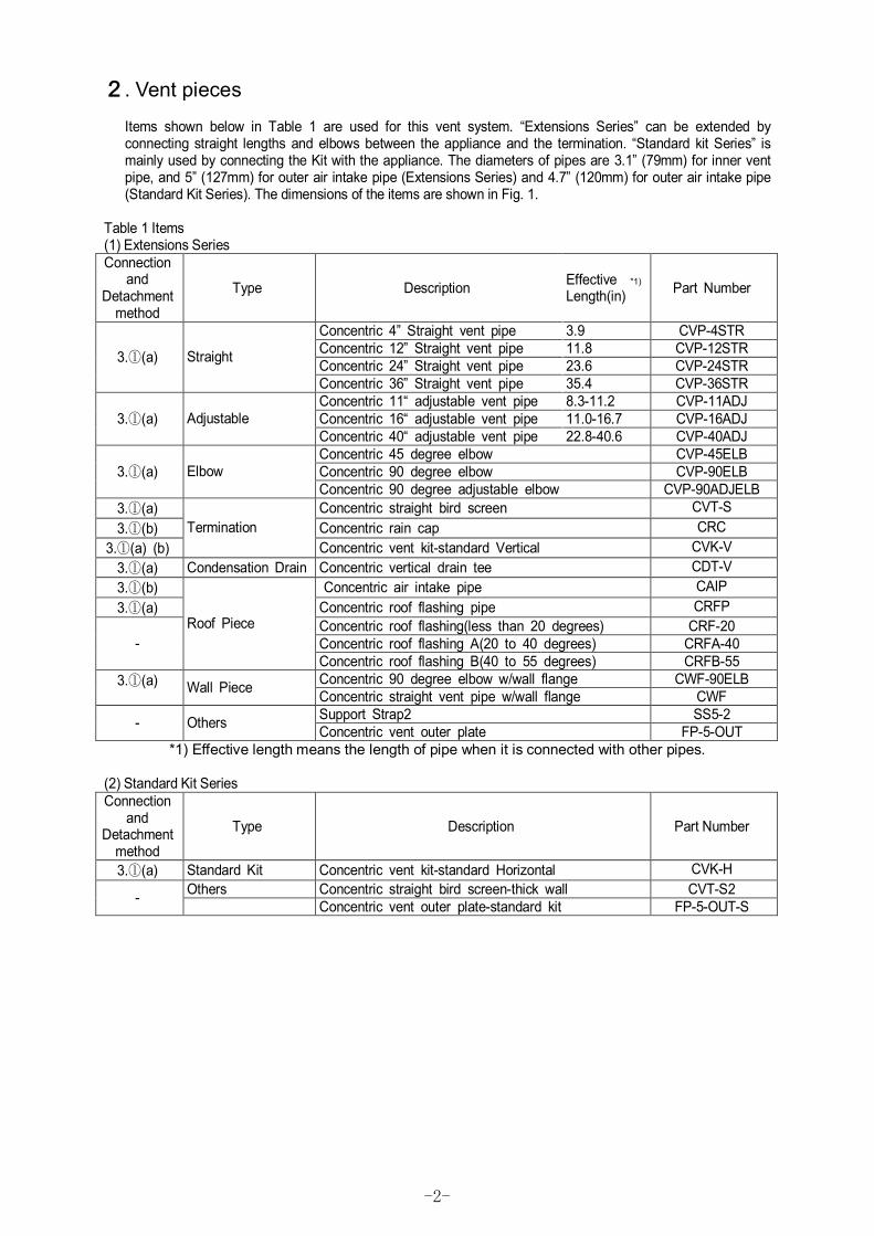
2. Vent pieces
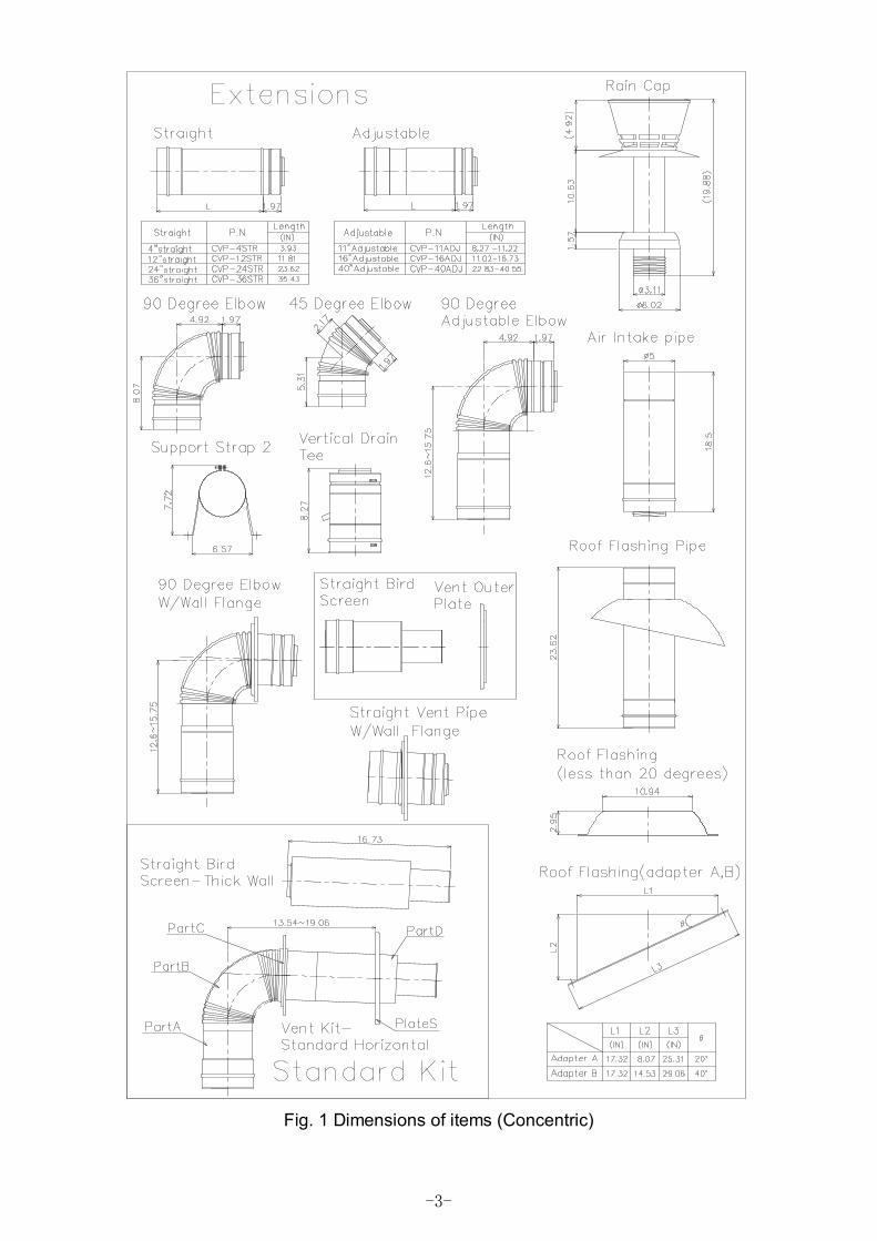
Items shown below in Table 1 are used for this vent system. “Extensions Series” can be extended by connecting straight lengths and elbows between the appliance and the termination. “Standard kit Series” is mainly used by connecting the Kit with the appliance. The diameters of pipes are 3.1” (79mm) for inner vent pipe, and 5” (127mm) for outer air intake pipe (Extensions Series) and 4.7” (120mm) for outer air intake pipe (Standard Kit Series). The dimensions of the items are shown in Fig. 1.
Table 1 Items (1) Extensions Series Connection
and Detachment
method
Type Description Effective *1) Length(in) Part Number
Concentric 4” Straight vent pipe 3.9 CVP-4STR Concentric 12” Straight vent pipe 11.8 CVP-12STR Concentric 24” Straight vent pipe 23.6 CVP-24STR 3.①(a) Straight
Concentric 36” Straight vent pipe 35.4 CVP-36STR Concentric 11“ adjustable vent pipe 8.3-11.2 CVP-11ADJ Concentric 16“ adjustable vent pipe 11.0-16.7 CVP-16ADJ 3.①(a) Adjustable Concentric 40“ adjustable vent pipe 22.8-40.6 CVP-40ADJ Concentric 45 degree elbow CVP-45ELB Concentric 90 degree elbow CVP-90ELB 3.①(a) Elbow Concentric 90 degree adjustable elbow CVP-90ADJELB
3.①(a) Concentric straight bird screen CVT-S 3.①(b) Concentric rain cap CRC
3.①(a) (b) Termination
Concentric vent kit-standard Vertical CVK-V 3.①(a) Condensation Drain Concentric vertical drain tee CDT-V 3.①(b) Concentric air intake pipe CAIP 3.①(a) Concentric roof flashing pipe CRFP
Concentric roof flashing(less than 20 degrees) CRF-20 Concentric roof flashing A(20 to 40 degrees) CRFA-40 -
Roof Piece
Concentric roof flashing B(40 to 55 degrees) CRFB-55 Concentric 90 degree elbow w/wall flange CWF-90ELB 3.①(a) Wall Piece Concentric straight vent pipe w/wall flange CWF Support Strap2 SS5-2 - Others Concentric vent outer plate FP-5-OUT
*1) Effective length means the length of pipe when it is connected with other pipes. (2) Standard Kit Series Connection
and Detachment
method
Type Description Part Number
3.①(a) Standard Kit Concentric vent kit-standard Horizontal CVK-H Others Concentric straight bird screen-thick wall CVT-S2 - Concentric vent outer plate-standard kit FP-5-OUT-S
-3-
Fig. 1 Dimensions of items (Concentric)
-4-
3. Installation procedures
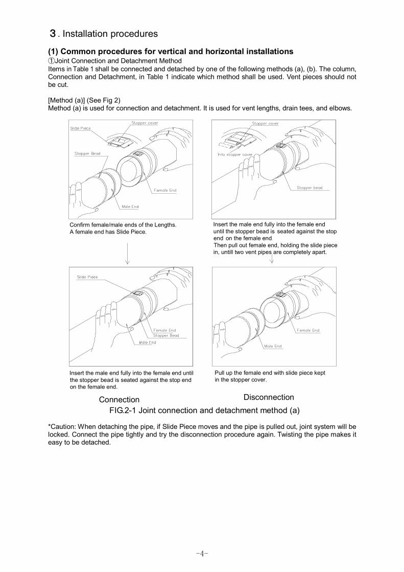
(1) Common procedures for vertical and horizontal installations ①Joint Connection and Detachment Method Items in Table 1 shall be connected and detached by one of the following methods (a), (b). The column, Connection and Detachment, in Table 1 indicate which method shall be used. Vent pieces should not be cut. [Method (a)] (See Fig 2) Method (a) is used for connection and detachment. It is used for vent lengths, drain tees, and elbows.
DisconnectionConnection
Insert the male end fully into the female enduntil the stopper bead is seated against the stopend on the female endThen pull out female end, holding the slide piecein, untill two vent pipes are completely apart.
Pull up the female end with slide piece keptin the stopper cover.
Confirm female/male ends of the Lengths. A female end has Slide Piece.
Insert the male end fully into the female end untilthe stopper bead is seated against the stop end on the female end.
FIG.2-1 Joint connection and detachment method (a)
*Caution: When detaching the pipe, if Slide Piece moves and the pipe is pulled out, joint system will be locked. Connect the pipe tightly and try the disconnection procedure again. Twisting the pipe makes it easy to be detached.

-5-
** Joint Structure
Fig 2-2 Structure
Fig 2-4 To detach the pipes
Fig 2-3 Unfasten Prevention Mechanism
[Unfasten Prevention Mechanism] (Fig.2-3) Pull the male without pushing Slide Piece to Stopper Cover, Slide Piece goes down into the gutter of male and two pipes are locked.
[To detach the pipes] (Fig.2-4) Pull the male pipe with pushing Slide Piece to Stopper Cover, Slide Piece goes up onto the male and two pipes are detached.

-6-
[Method (b) ] (See Fig 3) The rain cap, air intake pipe, and roof flashing pipe shall be connected by turning the screw at each end of pipes clockwise as far as they will go, as shown in Fig.3. When connecting between air intake pipe and roof flashing pipe, confirm that the end of air intake pipe reaches the outer bead of roof flashing pipe because the screw section is hidden in outer pipe. When disconnecting them, turn counterclockwise.
Fig.3 Joint connection and detachment method (b)
②Adjustable Lengths
Adjustable lengths are available to allow for installation where fixed-length sections do not produce the desired dimensions. Also adjustable lengths may be used to compensate for linear thermal expansion/contract between two fixed points. As shown in Table1, 3 types of adjustable lengths are available according to the limits in which its effective length can be made longer and shorter.
③Elbows 45°and 90°elbows are available for changing the direction of the vent system. The flexible section of each can be bent by hand for making small angle adjustment. Do not bend repeatedly or extremely, because it may cause vent gas leaks.
④Drain tee Connect the drain tee directly on the appliance flue outlet as shown in Fig.4-2 Attach one end of a drain hose to the drain tee outlet, and other end to a condensate drain so that any steam or condensed water will be handled properly. U trap must be formed into the drain hose so that exhaust gas will not go out through the drain hose. The drain hose must be suitable for use with acidic effluent. Follow the appliance manufacturer’s instructions, and all local and national codes for draining the condensate and acidic effluent. Caution : Periodically check the terminal end to ensure it is not blocked or obstructed.
Position the drain tee as close to the appliance as possible. ⑤Support strap
Support the vent system every 7ft (2.1m). 1. Secure the support to solid material using the screws provided with the support. 2. Loosen the nuts of the cylinder. After inserting pipes, fasten the loosened nuts. Use the pairs of
nuts and bolts provided with the support.
-7-
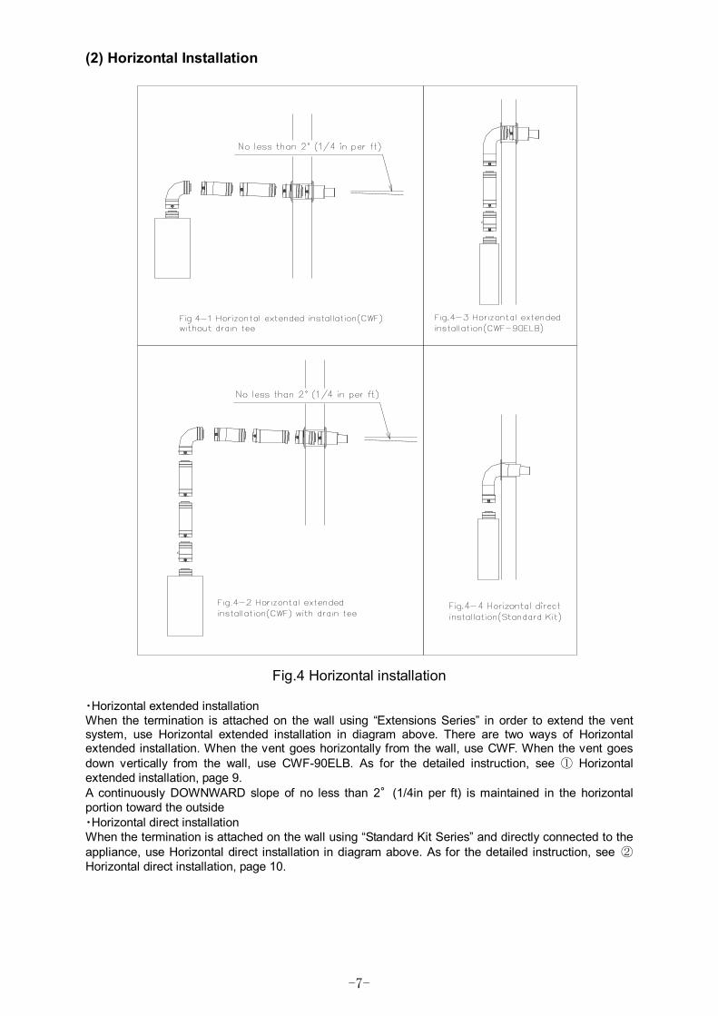
(2) Horizontal Installation
Fig.4 Horizontal installation
・Horizontal extended installation When the termination is attached on the wall using “Extensions Series” in order to extend the vent system, use Horizontal extended installation in diagram above. There are two ways of Horizontal extended installation. When the vent goes horizontally from the wall, use CWF. When the vent goes down vertically from the wall, use CWF-90ELB. As for the detailed instruction, see ① Horizontal extended installation, page 9. A continuously DOWNWARD slope of no less than 2°(1/4in per ft) is maintained in the horizontal portion toward the outside ・Horizontal direct installation When the termination is attached on the wall using “Standard Kit Series” and directly connected to the appliance, use Horizontal direct installation in diagram above. As for the detailed instruction, see ② Horizontal direct installation, page 10.
-8-
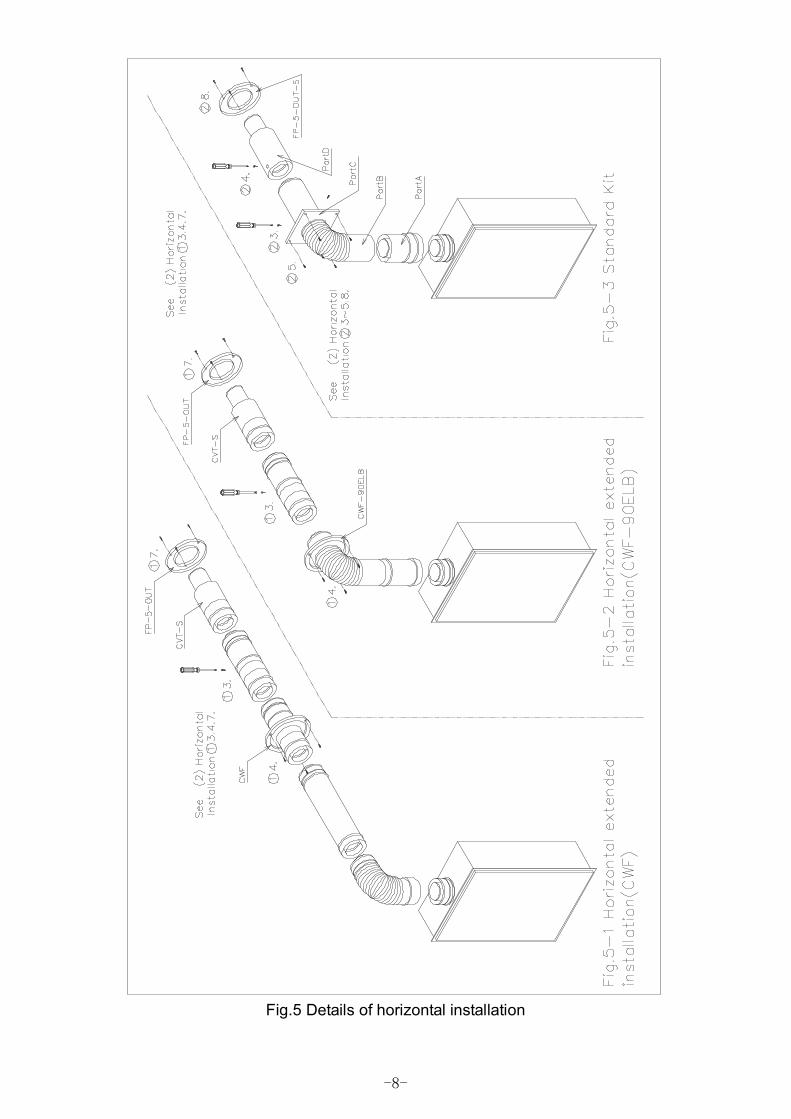
Fig.5 Details of horizontal installation
-9-
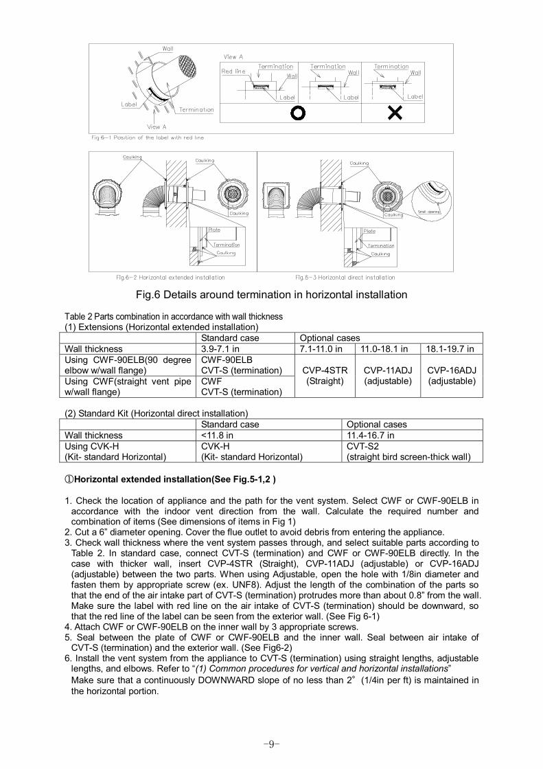
Fig.6 Details around termination in horizontal installation
Table 2 Parts combination in accordance with wall thickness (1) Extensions (Horizontal extended installation) Standard case Optional cases Wall thickness 3.9-7.1 in 7.1-11.0 in 11.0-18.1 in 18.1-19.7 in Using CWF-90ELB(90 degree elbow w/wall flange)
CWF-90ELB CVT-S (termination)
Using CWF(straight vent pipe w/wall flange)
CWF CVT-S (termination)
CVP-4STR (Straight)
CVP-11ADJ (adjustable)
CVP-16ADJ (adjustable)
(2) Standard Kit (Horizontal direct installation) Standard case Optional cases Wall thickness <11.8 in 11.4-16.7 in Using CVK-H (Kit- standard Horizontal)
CVK-H (Kit- standard Horizontal)
CVT-S2 (straight bird screen-thick wall)
①Horizontal extended installation(See Fig.5-1,2 ) 1. Check the location of appliance and the path for the vent system. Select CWF or CWF-90ELB in
accordance with the indoor vent direction from the wall. Calculate the required number and combination of items (See dimensions of items in Fig 1)
2. Cut a 6” diameter opening. Cover the flue outlet to avoid debris from entering the appliance. 3. Check wall thickness where the vent system passes through, and select suitable parts according to
Table 2. In standard case, connect CVT-S (termination) and CWF or CWF-90ELB directly. In the case with thicker wall, insert CVP-4STR (Straight), CVP-11ADJ (adjustable) or CVP-16ADJ (adjustable) between the two parts. When using Adjustable, open the hole with 1/8in diameter and fasten them by appropriate screw (ex. UNF8). Adjust the length of the combination of the parts so that the end of the air intake part of CVT-S (termination) protrudes more than about 0.8” from the wall. Make sure the label with red line on the air intake of CVT-S (termination) should be downward, so that the red line of the label can be seen from the exterior wall. (See Fig 6-1)
4. Attach CWF or CWF-90ELB on the inner wall by 3 appropriate screws. 5. Seal between the plate of CWF or CWF-90ELB and the inner wall. Seal between air intake of
CVT-S (termination) and the exterior wall. (See Fig6-2) 6. Install the vent system from the appliance to CVT-S (termination) using straight lengths, adjustable
lengths, and elbows. Refer to “(1) Common procedures for vertical and horizontal installations” Make sure that a continuously DOWNWARD slope of no less than 2°(1/4in per ft) is maintained in the horizontal portion.
-10-
7. Attach FP-5-OUT on the outer wall with 3 appropriate screws. Make the label “UP” on the FP-5-OUT upward. Seal between FP-5-OUT and outer wall. (See Fig6-2) ②Horizontal direct installation(See Fig.5-3 ) 1. Check the location of appliance and the Termination. Adjust the vertical position so that vent
kit-standard Horizontal can be connected to the appliance by the adjustable mechanism of Part A/B of CVK-H (Vent kit-standard Horizontal).
2. Cut the opening with 6in diameter. Cover the flue outlet to avoid debris from entering the appliance. 3. CVK-H consists of 5 parts, Part A (indoor part, straight pipe with connection mechanism), Part B
(indoor part, elbow with straight pipe), Part C (indoor part, square plate), Part D (outdoor part, termination) and FP-5-OUT-S (outdoor part). Connect Part A and Part B to make the elbow adjustable. Fasten Part B and Part C with 3 provided screws.
4. Check wall thickness where the vent system passes through. Select suitable parts according to Table 2. In standard case, no parts should be needed. In the case with thicker wall, replace Part D to CVT-S2 (straight bird screen-thick wall). To fix horizontal adjustable mechanism, open the hole with 1/8in diameter and fasten them by appropriate screw (ex. UNF8). Adjust the length of the combination of the parts so that the end of the air intake part of the Termination protrudes about 0.8” from the wall. Make sure the label with red line on the air intake of termination should be downward, so that the red line of the label can be seen from the exterior wall. (See Fig 6-1)
5. Attach Part C (indoor part square plate) on the inner wall by 4 appropriate screws. 6. Seal between Part C and the inner wall. Seal between air intake of Part D (outdoor part,
termination) and the exterior wall. (See Fig6-3) 7. Connect CVK-H to the appliance using the vertical adjustable mechanism. 8. Seal between termination and the outer wall. (See Fig6-2) Attach FP-5-OUT-S on the outer wall with 3 appropriate screws. Then, seal between FP-5-OUT-S and the outer wall, and also seal between FP-5-OUT-S and terminations. Seal the small opening of FP-5-OUT-S tight. (See Fig6-3) (3) Vertical Installation
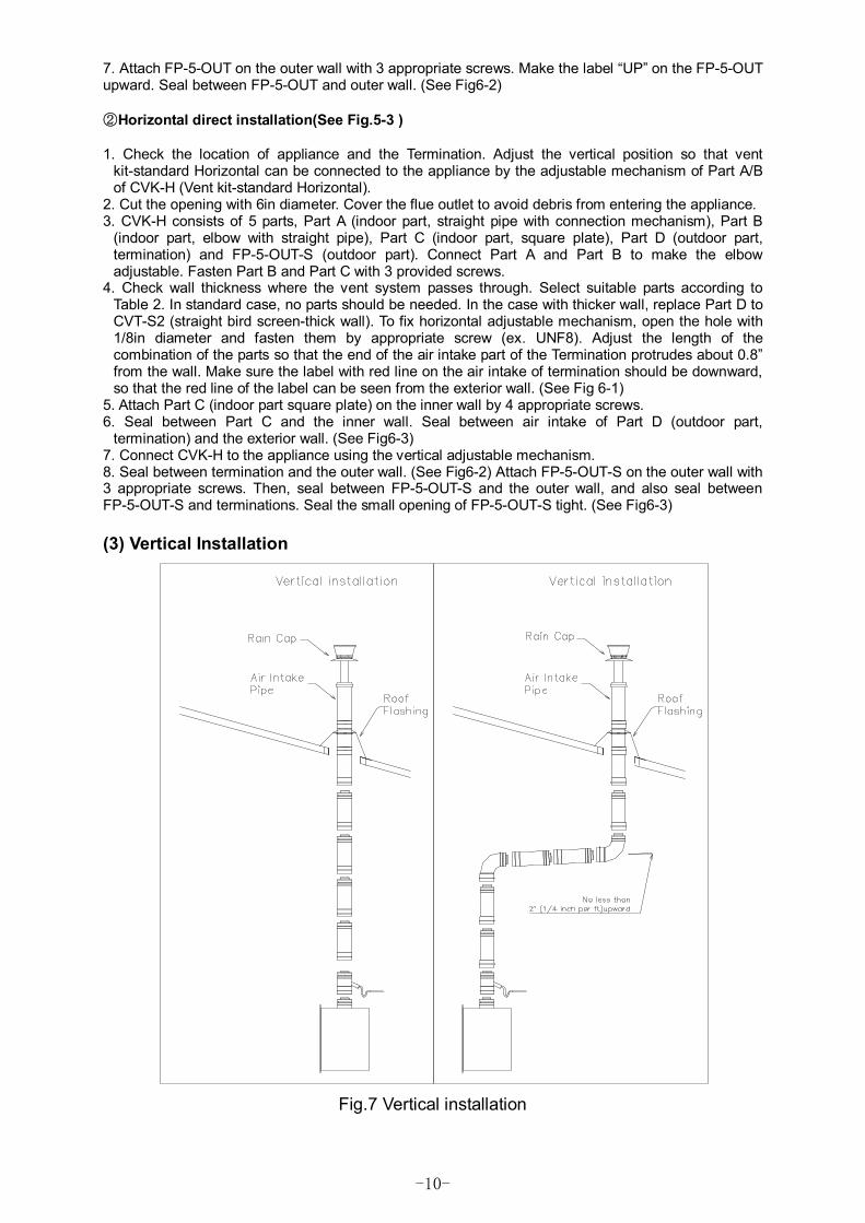
Fig.7 Vertical installation
-11-
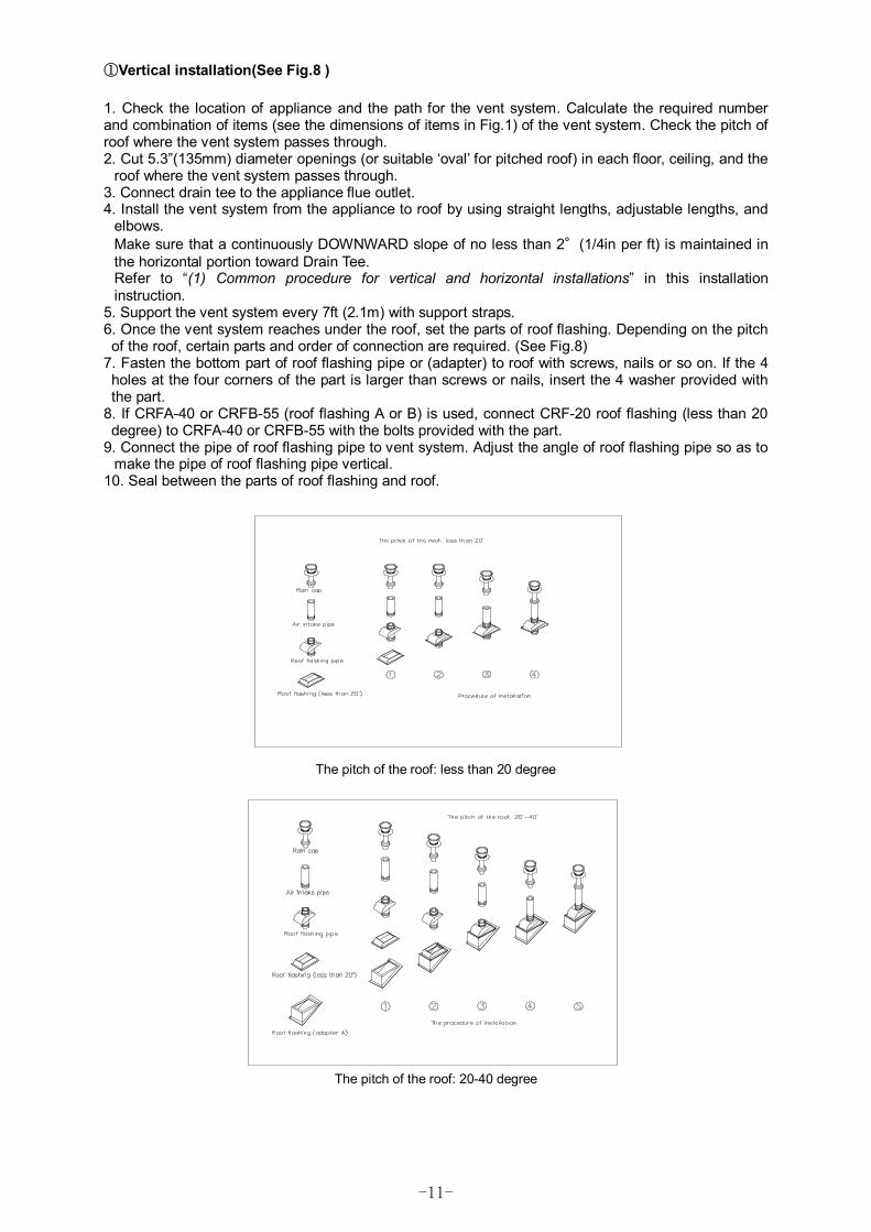
①Vertical installation(See Fig.8 ) 1. Check the location of appliance and the path for the vent system. Calculate the required number and combination of items (see the dimensions of items in Fig.1) of the vent system. Check the pitch of roof where the vent system passes through. 2. Cut 5.3”(135mm) diameter openings (or suitable ‘oval’ for pitched roof) in each floor, ceiling, and the
roof where the vent system passes through. 3. Connect drain tee to the appliance flue outlet. 4. Install the vent system from the appliance to roof by using straight lengths, adjustable lengths, and
elbows. Make sure that a continuously DOWNWARD slope of no less than 2°(1/4in per ft) is maintained in the horizontal portion toward Drain Tee. Refer to “(1) Common procedure for vertical and horizontal installations” in this installation instruction.
5. Support the vent system every 7ft (2.1m) with support straps. 6. Once the vent system reaches under the roof, set the parts of roof flashing. Depending on the pitch of the roof, certain parts and order of connection are required. (See Fig.8)
7. Fasten the bottom part of roof flashing pipe or (adapter) to roof with screws, nails or so on. If the 4 holes at the four corners of the part is larger than screws or nails, insert the 4 washer provided with the part.
8. If CRFA-40 or CRFB-55 (roof flashing A or B) is used, connect CRF-20 roof flashing (less than 20 degree) to CRFA-40 or CRFB-55 with the bolts provided with the part.
9. Connect the pipe of roof flashing pipe to vent system. Adjust the angle of roof flashing pipe so as to make the pipe of roof flashing pipe vertical.
10. Seal between the parts of roof flashing and roof.
The pitch of the roof: less than 20 degree
The pitch of the roof: 20-40 degree

-12-
The pitch of the roof: 40-55 degree
FIG 8 Details of vertical installation
N-Vent
NORITZ AMERICA CORPORATION
11160 Grace Avenue, Fountain Valley, CA 92708
www.noritz.com