Embed Size (px)
Citation preview

Concentric Horizontal Vent Kit
FOR BOSCH GREENTHERM C950ES, C1050ES TANKLESS WATER HEATERS
Installation Instructions
2 | Concentric Horizontal Vent Kit
Bosch Thermotechnology Corp.Data subject to change
Installation Manual

Installation Manual Concentric Horizontal Vent Kit | 3
Bosch Thermotechnology Corp. Data subject to change
Table of Contents
1 Explanation Of Symbols 41.1 Key To Symbols 4
1.2 Safety Instructions 4
2 Scope Of Delivery 6
3 Installation 73.1 Notes On Installation 7
3.2 Appliance Adapter 8
3.3 Elbow and Wall Termination 8
3.4 Redirecting The Vent Discharge 10
4 Spare Parts 11
4 | Concentric Horizontal Vent Kit
Bosch Thermotechnology Corp.Data subject to change
Installation Manual
1 Explanation Of Symbols
1.1 Key To Symbols
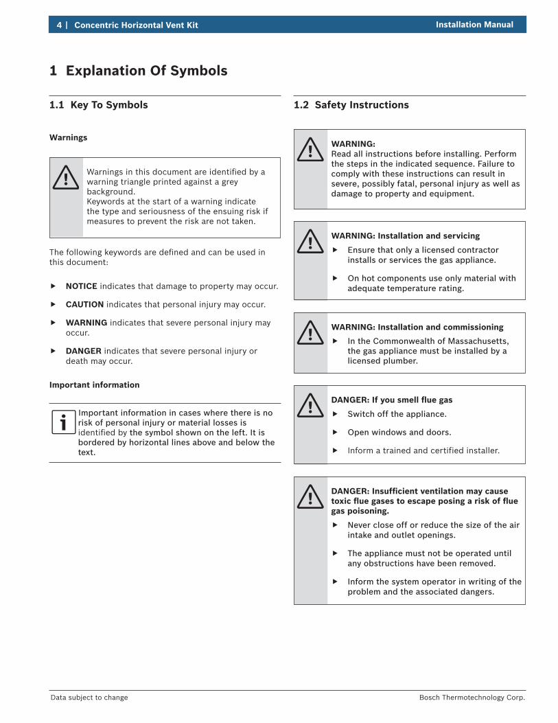
Warnings
Warnings in this document are identifi ed by a warning triangle printed against a grey background.Keywords at the start of a warning indicate the type and seriousness of the ensuing risk if measures to prevent the risk are not taken.
The following keywords are defi ned and can be used in this document:
NOTICE indicates that damage to property may occur.
CAUTION indicates that personal injury may occur.
WARNING indicates that severe personal injury may occur.
DANGER indicates that severe personal injury or death may occur.
Important information
Important information in cases where there is no risk of personal injury or material losses is identifi ed by the symbol shown on the left. It is bordered by horizontal lines above and below the text.
1.2 Safety Instructions
WARNING:Read all instructions before installing. Perform the steps in the indicated sequence. Failure to comply with these instructions can result in severe, possibly fatal, personal injury as well as damage to property and equipment.
WARNING: Installation and servicing
Ensure that only a licensed contractor installs or services the gas appliance.
On hot components use only material with adequate temperature rating.
WARNING: Installation and commissioning
In the Commonwealth of Massachusetts, the gas appliance must be installed by a licensed plumber.
DANGER: If you smell fl ue gas
Switch off the appliance.
Open windows and doors.
Inform a trained and certified installer.
DANGER: Insuffi cient ventilation may cause toxic fl ue gases to escape posing a risk of fl ue gas poisoning.
Never close off or reduce the size of the air intake and outlet openings.
The appliance must not be operated until any obstructions have been removed.
Inform the system operator in writing of the problem and the associated dangers.

Installation Manual Concentric Horizontal Vent Kit | 5
Bosch Thermotechnology Corp. Data subject to change
WARNING: Danger from escaping fl ue gases
Ensure all vent pipes and chimneys are not damaged or blocked.
Connect only one appliance to each vent system or chimney liner.
The venting system piping must not feed into another air exhaust duct.
Do not route the flue system piping through or inside another air exhaust duct.
WARNING: Combustion air
Keep the combustion air free of corrosive substances (halogenated hydrocarbons that contain chlorine or fluorine compounds).
WARNING: MaintenanceCustomers are advised to:
Sign a maintenance and inspection contract with an authorized contractor. Inspect and maintain the gas appliance as necessary and on a yearly basis. Service as needed.
Use only genuine spare parts.
DANGER: Fatal accidents!Carbon monoxide poisoning.
Carefully plan where you install the gas appliance. Correct combustion air supply and flue pipe installation are very important. If a gas appliance is not installed correctly, fatal accidents can result such as carbon monoxide poisoning or fire.
DANGER: Carbon monoxide poisoning.
Exhaust gas must be vented to outside using approved vent material. (In Canada use only ULCS636 approved material). Vent and combustion air connector piping must be sealed gas-tight to prevent flue gas spillage, carbon monoxide emissions and risk of fire, resulting in severe personal injury or death. Approved vent terminations must be used when penetrating to the outside.
WARNING:
Do not obstruct the flow of combustion and ventilation air.
NOTICE:
The installation must comply with national, state, and local code, and the gas appliance Installation Instructions and this Vent System Installation Manual must be followed exactly.

Fig. 1 Scope of delivery - dimensions in inches (mm) Fig.1 Legend:
1 90° elbow 2 Telescopic terminal assembly 3 Inner wall seal 4 Outer wall seal 5 Screws and wall anchors 6 Connecting screws 7 Securing screws 8 Appliance adapter and gasket 9 Air vent blind cover and gasket Needed Tools:
- Hole saw - Tape measure - Phillips screw driver - Bottled water (as lubricant for gaskets) - Weatherproof caulk

Installation Manual Concentric Horizontal Vent Kit | 7
Bosch Thermotechnology Corp. Data subject to change
3 Installation
3.1 Notes On Installation
NOTICE: It is the installer's responsibility that the appliance is installed according to the manufacturer's installation instructions, this accessory manual, as well as national, state, and local local code.
CAUTION: The location and orientation of the vent termination must follow those stated in the relevant appliance Instruction Manual. When redirecting the fl ue discharge ensure it does not create a hazard or nuisance.
NOTICE: The concentric vent kit is approved for zero (0", 0 mm) clearance to combustibles.
NOTICE: This vent system is ULC-S636 certifi ed for Canada.
WARNING:
The concentric vent system is only approved in an up-and-out configuration. No pipe extensions or modifications are permitted.
CAUTION:
Ensure the termination is installed at least 12" (300 mm) above the average snow line. If this is not feasible, this termination can not be used.
Fi
1
3
2
g. 2
Fig. 2 Legend:1 Termination2 Direction of fl ue discharge3 Plume defl ector

8 | Concentric Horizontal Vent Kit
Bosch Thermotechnology Corp.Data subject to change
Installation Manual
3.2 Appliance Adapter
Use the blind cover and gasket supplied with the kit to close the second combustion air opening on the top of the appliance ( Fig. 3).
Fig. 3 Covering second combustion air opening
Discard original appliance adapter that was supplied with the tankless water heater. If the unit came with a combustion air adapter, discard as well.
The adapter gasket has a circular grove to engage with the vent pipe of the appliance. Place it onto the pipe and press down fi rmly.
Fig. 4 Installing adapter gasket
Set the appliance adapter down onto the pipe ensuring that the analyzer ports are facing to the front of the appliance and the adapter screw holes are aligning with those of the appliance.
Fig. 5 Installing adapter
Insert the 4 screws, but do not tighten all the way.
3.3 Elbow and Wall Termination
Apply a small amount of clean water as lubricant on all gaskets.
Place elbow on top of the appliance adapter and align.
Fig. 6 Installing elbow
While the screws are not fully tightened, the appliance adapter can be swivelled around its vertical axis.

Installation Manual Concentric Horizontal Vent Kit | 9
Bosch Thermotechnology Corp. Data subject to change
Measure the length of the vent terminal assembly (Fig. 7, [1]) taking into account the thickness of the outside wall [S] and the distance from the outside wall to the end of the vent pipe [L]. It is recommended to keep at least 4" (100mm) clearance from the ceiling or joists for accessibility reasons.
F
L
13³/₁₆" - 20⅞"(335 - 530mm)
1/4" per foot (50 mm per meter)
K
S1
≥ 4"
(100
mm
)
ig. 7 Penetration through the outside wall
Select the required diameter [K] of the hole in the wall according to the wall thickness S.
Sizing hole penetration
Wall Thickness S Diameter K
6" - 9 ½" (150 - 240 mm) 6 1/4" (155 mm)
9 ½" - 16½" (240 - 420 mm) 6 1/2" (165 mm)
16½" - 20 ⅞" (420 - 530 mm) 7" (170 mm)
Cut the hole in the wall while allowing clearance for the required pitch of the air/vent pipe.
Adjust the vent pipe length to the distance [L] required & secure with three self tapping screws [2].
12
L13³/₁₆" - 20⅞"(335 - 530mm)
1.
2.
3x
Fig. 8
Slide the outer wall seal [2] onto the terminal [1] as shown.
1 2
Fig. 9
Position terminal [1] from the outside through the vent opening so rubber thimble [2] is flush against outside wall .
Slide the inner wall seal [3] onto the terminal [1] as shown.
1.2.
13 2
Fig. 10 Inserting termination from the outside
Connect the termination to the elbow.
Fig. 11 completed adapter and concentric assembly

10 | Concentric Horizontal Vent Kit
Bosch Thermotechnology Corp.Data subject to change
Installation Manual
Ensure all components are properly connected and aligned, and that the termination has the proper pitch as shown in Fig. 7.
Tighten the four screws of the appliance adapter on the water heater.
Complete installing the appliance per the Water Heater Installation Instructions.
3.4 Redirecting The Vent Discharge
The vent discharge can be redirected to reduce the risk of cross contamination.
Remove the screws [A] and disconnect the terminal end [B].
B
2.1.
A
Fig. 11
Rotate the terminal end [B] 180° so discharge faces upwards.
Refit the terminal end [B] and tighten the screws [A].
B
180°
A
Fig. 12
The entire termination can now be rotated left or right ±40° to redirect the plume ( Fig. 13).
±80 °
Fig. 13
Use adequate weather resistant caulk to seal the penetration in the wall and prevent moisture damage.
When redirecting the fl ue discharge ensure it does not create a hazard or nuisance.

Installation Manual Concentric Horizontal Vent Kit | 11
Bosch Thermotechnology Corp. Data subject to change
4 Spare Parts
Spare Parts List
Part Number Description
7 736 501 235 Concentric Up & Out Vent Kit Complete
7 736 501 234 Appliance Adapter Concentric
8 704 701 108 Adapter blue gasket
7 736 501 523 Combustion air cover and gasket, adapter blue gasket

United States and Canada
Bosch Thermotechnology Corp.50 Wentworth AvenueLondonderry, NH 03053
Tel: 603-552-1100Fax: 603-965-7581www.bosch-climate.us
BTC 740001302 A / 02.2013