Embed Size (px)
Citation preview

MZ002-099-4115AB: 2019/07/02
Instruction manual
Mode d’emploi
Betriebsanleitung
Istruzioni d’uso
Manual de instrucciones
Installatie voorschrift
w w w . i t r o n . c o m

1 / 6 D2035933_AE_EU_Declaration_MZ.doc
EU Declaration of Conformity Itron GmbH
Hardeckstraße 2 D-76185 Karlsruhe
Declares on his sole responsibility that the product Quantometer MZ/MTZ is designed and manufactured in conformity with the following Directives:
1. Directive 2014/68/EU (PED) Modules B+D Category IV - DIN EN 12261:2007-07
Certificate DVGW CE-0085BS5061 The module D is supervised by: TÜV SÜD Industrie Service GmbH (CE:0036) Westendstr. 199, D-80686 München The used fluids are classified in group 1 according article 13. Certificate: DGR-0036-QS-955-17
2. Directive 2014/30/EU (EMC) - EN 60947-5-2:2007/A1:2012 - EN 61000-6-2:2005/AC:2005 - EN 61000-6-3:2007/A1:2011/AC:2012;
3. Directive 2014/34/EU (ATEX)
- EN 60079-0:2012/A11:2013 - EN 60079-11:2012 - EN 13463-1:2009 - EN 13463-5:2011
Certificate: LCIE 06 ATEX 6031 X II 1/2 G Ex ia IIC T5 Ga / Gb c T6 #0081 LCIE 33 avenue General Leclerc, F-92266 Fontenay-aux-Roses The module D is supervised by: #0123 TÜV SÜD Product Service GmbH Ridlerstr. 65, D-80339 München Certificate: EX2A 17 05 70229 004
4. Directive 2011/65/EU (RoHS) - EN 50581:2012
Karlsruhe, April 11st 2018
K. Zinnitsch
Managing director

3
ENG
LISH
1 Characteristics . . . . . . . . . . . . . . . . . . . . . . . . . . . . . . . . . . . . . . . . . . . . . . . . . . . . . . . . . . . 4
2 PackingoftheMZ . . . . . . . . . . . . . . . . . . . . . . . . . . . . . . . . . . . . . . . . . . . . . . . . . . . . . . . 4 2 .1 Packing . . . . . . . . . . . . . . . . . . . . . . . . . . . . . . . . . . . . . . . . . . . . . . . . . . . . . . . . . . . . . 4 2 .2 Storage . . . . . . . . . . . . . . . . . . . . . . . . . . . . . . . . . . . . . . . . . . . . . . . . . . . . . . . . . . . . . 4 2 .3 Handling . . . . . . . . . . . . . . . . . . . . . . . . . . . . . . . . . . . . . . . . . . . . . . . . . . . . . . . . . . . . 4
3 Installation . . . . . . . . . . . . . . . . . . . . . . . . . . . . . . . . . . . . . . . . . . . . . . . . . . . . . . . . . . . . . . . 4 3 .1 Generalrecommendations . . . . . . . . . . . . . . . . . . . . . . . . . . . . . . . . . . . . . . . . . . . . 5 3 .2 RecommendedInstallation . . . . . . . . . . . . . . . . . . . . . . . . . . . . . . . . . . . . . . . . . . . . 5 3 .3 Startup . . . . . . . . . . . . . . . . . . . . . . . . . . . . . . . . . . . . . . . . . . . . . . . . . . . . . . . . . . . . . 5 3 .3 .1 Installationwithanupstreamvalve . . . . . . . . . . . . . . . . . . . . . . . . . . . . . 5 3 .3 .2 Installationwithupstreamanddownstreamvalves . . . . . . . . . . . . . . . 5 3 .3 .3 Installationwithaby-pass . . . . . . . . . . . . . . . . . . . . . . . . . . . . . . . . . . . . . 5
4 Transmitters . . . . . . . . . . . . . . . . . . . . . . . . . . . . . . . . . . . . . . . . . . . . . . . . . . . . . . . . . . . . . 5
5 Maintenance . . . . . . . . . . . . . . . . . . . . . . . . . . . . . . . . . . . . . . . . . . . . . . . . . . . . . . . . . . . . 6 5 .1 Lubrication . . . . . . . . . . . . . . . . . . . . . . . . . . . . . . . . . . . . . . . . . . . . . . . . . . . . . . . . . . 6 5 .2 Externalsilicagelcartridge . . . . . . . . . . . . . . . . . . . . . . . . . . . . . . . . . . . . . . . . . . . . 6 5 .3 Inspectionandrepair . . . . . . . . . . . . . . . . . . . . . . . . . . . . . . . . . . . . . . . . . . . . . . . . . 6
6 Annex . . . . . . . . . . . . . . . . . . . . . . . . . . . . . . . . . . . . . . . . . . . . . . . . . . . . . . . . . . . . . . . . . .37

4
Keepthismanualeasilyaccessibleforallusers .Pleaserespectallnationalrulesforinstallation,operationandserviceofgasmeters .
1 Characteristics: Turbinesgasmetersareflowmeters .Theflowofgasturnsaturbinewheelandtherotating speed of the turbine is propor-tional tothe linearspeedof thegas .Themovement ismechanicallytransmittedtothe totaliser through the magnetic cou-pling .DetailedcharacteristicsaregiveninAnnex1
2 Packing of the MZ
2.1 PackingThemeter,dependingonthesizeisde-liveredinanindividualcartonboxoronawoodpallet .Thepackagingcontainstheplugsfortheinstalledtransmittersandthelubricantwhenanoilpumpisinstalled .
2.2 StorageIfthemeterisnotgoingtobeusedimme-diately,itshouldbestoredundercoverinaclean,dryenvironment .Thecapsfittedattheinletandtheoutletpipemuststayinplaceuntilinstallation .Storingtempera-ture:-40°Cto+70°C .
2.3 HandlingMetersshouldbehandledwithcare .Theymustbeliftedonlywithbeltsaroundthemainbodyorontheeyelets .
3 Installation
3.1 General recommendations: SeeAnnex2andPEDinformationinAnnex6
•ThestandardMZisdesignedforusewithcleanandnon-aggressivegases .Forusewith aggressive gases please contactItronforspecialversions .
•Ifthemeterisequippedwithanoilpump,turnoiltankaccordingtotheinstallationposition .
•(1)Beforeinstallation,checkvisuallythatthemeterhasnotbeendamagedduringtransport .
•(2)DoNOTweldpipeworkwithameterinstalled .
•(3)Themetershouldbeinstalledwith-outstress in thepipework .Theflangesmustbecorrectlylinedup .Thetighten-ingtorqueoftheboltsmustnotexceed(Nm):
M16 M2085 170
Pleasetightenboltsinoppositepairs .
•(4)Toensureaccuracy,Themeterhastobeinstalledwithaninletstraightpipeof3DNminimum .
•(5) Transmitters connection: Gas Me-ters areoften installed in areaswherethere isariskthatGaswillbepresent .Therefore,electricalconnectionstome-tersneedtobemadewithconsiderationof theuseofExmarkedequipmentorotherwiseapprovedcircuits .Forplugas-signmentandpulsevaluesrefertothemainnameplate .

5
ENG
LISH
•(6)Dirtparticlesmaydamagethetur-binewheelthereforetheuseofstartingsieveandfilterarerecommended .
•(7) Pressure pulses must be avoidedduringstartingandoperatingtopreservethe turbinewheel . Topreventdamageduring starting, increase the pressureslowlyatlessthan0,3barpersecond .
3.2 Recommended installation Turbinemetersareflowmetersthereforetheirmetrologycanbeaffectedbydistur-bancesexistingintheflowofgas .
Thebestaccuracyisachievedbyrespect-ingthefollowingrules:
•Usepreferablyelbowpieceswith largeradius (> 5 DN) to be installed at theinletofthemeter .
•Fordiametervariations,usepreferablyconcentric convergent and divergentpieces;suddenchangesmustbeavoid-ed .
•Obstaclessuchasthermowellsmustnotprotrude in the pipe within 2 DN up-streamofthemeter .Gasketsshouldbecorrectly centred between the flangesandnotprotrudeintothepipe .
3.3 Start up
3.3.1. Installation with an upstream valve
Openthevalveveryslowlyuntiltheme-terstartstooperate .Increaseslowlythepressure in the downstream pipe (max .0,3bar/second) .When thedownstreampressureisstabilised,openthevalvecom-pletely .
3.3.2 Installation with upstream and downstream valves
Closethedownstreamvalve .Openslowlytheupstreamvalve(max .0,3bar/second) .Whenthepressureisstabilisedintheme-ter,opengentlythedownstreamvalvetomaintainthepressureinthemeterandtoavoidoverflow .
3.3.3 Installation with a by-pass
Closeallvalves .Slowlyopentheby-passandwaituntilthedownstreampressureisstabilised .Thenproceedas§3 .3 .2 .Closethebypass .
Afterstartup,pleasecheckthetightnessoftheinstallation .Checkalsothatthemaxi-mumflowofthemeterisnotexceeded .
4 TransmittersTheMZisequippedasoptionwith2LowFrequency(LF),Reedswitchesandananti-tamperingswitch;withinductivemediumorhighfrequencies(HF)transmitters .ACyblesensorcanbealsoinstalledontotheto-taliser,seeAnnex3 .
Remarksaboutusingthemeterinpoten-tiallyhazardousareas(ATEX)
•Pulsetransmittersmustbeconnectedtocircuits intrinsic safecircuits,accordingtoEN60079-11 .
•Cleanthemeterheadonlywithadampcloth .
•All exposed aluminium parts must besuitablyprotected(usingpaint,varnish,etc)ifafilmofrustispossiblefromdustintheenvironment .
•Themetermustbeearthed .
•Tools used for installing, removing, orrepairingthemeteronsitemustbeap-propriateforuseinthehazardousarea

bearinginmindthatthehazardousareaclassificationduringmeterreplacementmaydifferfromthatduringnormalme-teroperations .
•Themetershallnotbeexposedtoflames,ionisingradiation,andultrasound .
•Pulse values and maximum frequen-cies are given in Annex 1 . ElectricalcharacteristicsandwiringofthesocketaregiveninAnnex4 .Thewiringofthetransmittersiswrittenonthenameplateofthemeter .
5 MaintenanceWhenproperlyinstalledandputintoser-vice,theMZneednoparticularattentionandwillprovideyouwithmanyyearsofsatisfactoryservice .
5.1 LubricationMetersequippedwithanoilpumphavetobeperiodicallylubricated .Oilisdeliveredwiththemeter .Specificoilhastobeused,forexample
• Aeroshellfluid12MIL6085A• IsoflexPDP38(Klüber)• Anderol401D(MobilOil)• UnivisP38(Shell)
Quantityofoiltobefilled:
a)On commissioning to fill the volumebetweenthepumpandthebearings
DN Oilvol .(cm3) Push50/80 4 20100 5 25
150/200 6 30
b)InService
DN Oilvol .(cm3) Push
50/80 0,5 2-3100 0,8 4
150/200 1,0 5
c)Recommendedlubricationperiodicity
Application Lubricationperiodicity
Drygas,nodust 6months
Gascomprising Monthlylightcondensatesandlittledust
Gaswithhigh Weeklypercentageofcondensatesanddust . BIOGAS applications
5.2 External silicagel cartridgeThemetercanbeequippedwithanex-ternalsilicagelcartridgeforinstallationinsevereenvironmentconditions .Thecar-tridgehastobereplacedwhenitscolourhas changed . To replace the cartridge,unscrew the old cartridge, remove theprotectiveplugofthenewcartridgeandscrewitintothetotaliser .
5.3 Inspection and repairItispossibletocheckthegoodfunction-ingoftheMZbyapplyingaspintest .Thistestwillgive informationabouteventualfrictionintheturbineballbearings .
Thetesthastobeconductedasfollow:
•Acceleratetheturbinewheelaround30to50%ofQmaxthentomeasurethetimeuntiltheturbinewheelstops .
6

7
ENG
LISH
•Measurethespintime(ST)untilthetur-binewheelstops .
See Annex 5 for typical values of spintime .
The followingrecommendationshave tobeobservedforrepair:
•Incaseofusewithaggressiveordanger-ousgas,itmaybenecessarytosendasafetystatementwiththemeter,detail-ingthetypeofGasthathasbeenmea-sured .
•Somegasmaystillbepresentinsidethemeterandthepipe;thereforesufficientventilationisrequired .
•Repairsandmaintenancemustbedoneby trained or qualified personal . Afte-rwards a tightness test with 1 .1 x PS(Pmax)mustbeperformed .
•Whenchangingpressure-bearingparts,ensure that spare parts which complywiththePEDareused .
•Ifusedwithwetgas,internalandexter-naleffectofcorrosionhastobecheckedregularlyandincaseofseverecorrosion,themetermustbereplaced .
•Use solvent and alcohol free cleaningproducttocleanthemeter .

2 / 6 D2035933_AE_EU_Declaration_MZ.doc
Déclaration de Conformité UE Itron GmbH
Hardeckstrasse 2 D-76185 Karlsruhe
Déclare en sa seule responsabilité que le produit quantomètre MZ/MTZ est conçu et fabriqué en conformité avec les Directives suivantes :
1. Directive 2014/68/UE Modules B+D Catégorie IV – DESP - DIN EN 12261:2007-07
Certificat d’approbation de type n°: DVGW CE-0085BS5061 Le module D est supervisé par : #0036 TÜV SÜD Industrie Service GmbH, Westendstr. 199, D-80686 München Les fluides utilisés sont classifiés en groupe 1 suivant l´article 13. Certificat CE n°: DGR-0036-QS-955-17
2. Directive 2014/30/UE (EMC) Le produit est conforme à la Directive 2014/30/UE par le fait qu’il satisfait aux normes suivantes :
- EN 60947-5-2:2007/A1:2012 - EN 61000-6-2:2005/AC:2005 - EN 61000-6-3:2007/A1:2011/AC:2012;
3. Directive 2014/34/UE (ATEX)
Le produit est conforme aux normes suivantes : - EN 60079-0:2012/A11:2013 - EN 60079-11:2012 - EN 13463-1:2009 - EN 13463-5:2011
Certificat d’approbation de type n° : LCIE 06 ATEX 6031 X II 1/2 G Ex ia IIC T5 Ga / Gb c T6 #0081 LCIE 33 avenue General Leclerc, F-92266 Fontenay-aux-Roses Le module D (Annexe IV) est supervisé par : #0123 TÜV SÜD Product Service GmbH Ridlerstr. 65, D-80339 München Certificat CE n° : EX2A 17 05 70229 004
4. Directive 2011/65/UE (RoHS) - EN 50581:2012
Karlsruhe, 11 avril 2018
K. Zinnitsch
Directeur général

9
FRAN
CAI
SFR
AN
CA
IS
1 Caractéristiques . . . . . . . . . . . . . . . . . . . . . . . . . . . . . . . . . . . . . . . . . . . . . . . . 102 RéceptionduMZ/MTZ . . . . . . . . . . . . . . . . . . . . . . . . . . . . . . . . . . . . . . . . . . 10 2 .1 Emballage . . . . . . . . . . . . . . . . . . . . . . . . . . . . . . . . . . . . . . . . . . . . . . . . . . . . . . . . . .10 2 .2 Stockage . . . . . . . . . . . . . . . . . . . . . . . . . . . . . . . . . . . . . . . . . . . . . . . . . . . . . . . . . . .10 2 .3 Manutention . . . . . . . . . . . . . . . . . . . . . . . . . . . . . . . . . . . . . . . . . . . . . . . . . . . . . . . .10
3 Installation . . . . . . . . . . . . . . . . . . . . . . . . . . . . . . . . . . . . . . . . . . . . . . . . . . . . 10 3 .1 Généralités . . . . . . . . . . . . . . . . . . . . . . . . . . . . . . . . . . . . . . . . . . . . . . . . . . . . . . . . .10 3 .2 Installationrecommandée . . . . . . . . . . . . . . . . . . . . . . . . . . . . . . . . . . . . . . . . . . .11 3 .3 Miseenservice . . . . . . . . . . . . . . . . . . . . . . . . . . . . . . . . . . . . . . . . . . . . . . . . . . . . .11 3 .3 .1 Installationavecuniquementunevanneamont . . . . . . . . . . . . . . . . .11 3 .3 .2 Installationavecvannesamontetaval . . . . . . . . . . . . . . . . . . . . . . . . .12 3 .3 .3 Installationavecby-pass . . . . . . . . . . . . . . . . . . . . . . . . . . . . . . . . . . . . .12
4 Emetteursd‘impulsions . . . . . . . . . . . . . . . . . . . . . . . . . . . . . . . . . . . . . . . . . . 12
5 Entretien . . . . . . . . . . . . . . . . . . . . . . . . . . . . . . . . . . . . . . . . . . . . . . . . . . . . 12 5 .1 Lubrification . . . . . . . . . . . . . . . . . . . . . . . . . . . . . . . . . . . . . . . . . . . . . . . . . . . . . . . .12 5 .2 Cartouchesilicagelexterne . . . . . . . . . . . . . . . . . . . . . . . . . . . . . . . . . . . . . . . . . . .13 5 .3 Inspectionetréparation . . . . . . . . . . . . . . . . . . . . . . . . . . . . . . . . . . . . . . . . . . . . .13
6 Annexes . . . . . . . . . . . . . . . . . . . . . . . . . . . . . . . . . . . . . . . . . . . . . . . . . . . . . . . 37

10
Attention:ceproduitestunéquipementsouspression:lenonrespectdesinstruc-tions peut entraîner un danger pour lasécuritédesbiensetdespersonnes .
ItronGmbH,fabricantducompteur,dé-clinetouteresponsabilitédans lecasdunon respectde la totalitédespointsduprésentmoded‘emploiquidoitaccompa-gnerlecompteurpendanttoutesaduréedevie .
Serapprocheretdemanderl‘accordécritdufabricantpourtouslescasnonprévusdanslaprésentenoticed‘instructions .
Veuillezrespectertouteslesréglementa-tionsnationalespourl‘installation,l‘utilisa-tionetlamaintenancedescompteursdegaz .
1 Caractéristiques : Lescompteursàturbinesontdescomp-teursdevitesse .Lefluxdegazfaittournerla turbinedont lavitessederotationestproportionnelleàlavitesselinéairedugaz .Lemouvementesttransmismécanique-ment au totalisateur par l‘intermédiaired‘unecommandemagnétique .
Les caractéristiques détaillées sont don-néesenAnnexe1 .
2 Réception du MZ / MTZ
2.1 EmballageLecompteur,enfonctiondesatailleestlivrédansuncartonindividuelousurunepalette .L‘emballagecontientlesconnec-teurs pour les émetteurs d‘impulsionsinstallésetlelubrifiantlorsquelecomp-teurestéquipéd‘unepompeàhuile .
2.2 StockageSilecompteurn‘estpasutiliséimmédia-tement,ildoitêtrestockésousprotectiondansunlieusecetpropre .Lesoperculesinstallés sur lesbridesdoivent resterenplace jusqu‘à l‘installation du compteur .Température de stockage: -40 °C à+70°C
2.3 ManutentionLe compteur doit être manutentionnéavec attention . Il doit être manipulé àl‘aidedecâblespasséssous lecorpsoudanslesanneauxdelevageuniquement .
3 InstallationLe compteur doit impérativement êtreinstallédansunenvironnementdont lesconditionslimites(enparticulierpression,température, débit,…) sont compatiblesavec ses caractéristiques propres indi-quéessurlaplaquesignalétique .
3.1 Recommandations générales : VoirAnnexe2etl’informationPEDenAnnexe6
•Le MZ en version standard est conçupour mesurer des gaz propres et nonagressifs . Pour une utilisation avecdes gaz agressifs veuillez contacterItronpourdesversionsspéciales .
•Silecompteurestéquipéd‘unepompeàhuile,veuillezorientersonréservoirenfonction de l‘orientation du compteurdansleposte .
•(1)Avant l‘installation,vérifiervisuelle-mentque lecompteurn‘apasétéen-dommagédurantletransport .
•(2) Ne pas souder sur la canalisationlorsquelecompteurestmonté .
•(3) Le compteurdoit êtremonté sanscontraintesexcessivesdanslacanalisa-tion . Les brides doivent être correcte-mentalignées .Lecoupledeserragedesboulonsutiliséspour lesbridesnedoitpasexcéder(Nm):
M16 M2085 170
Veuillezserrerlesboulonsaucoupleencroix .
•(4)Pourassurerunebonneprécisiondemesure,lecompteurdoitêtremon-téavecunelongueurdroiteamontde3DNminimum .
•(5)Connexiondesémetteursd‘impul-sions:Lescompteursdegazpeuventêtreinstallésdansdeszonesoùdugazrisque d‘être présent . C‘est pourquoilesconnectionsélectriquesnedoiventêtre effectuées qu‘avec du matérielapprouvé de sécurité intrinsèque . Laconnexiondesbrochesestindiquéesurlaplaquesignalétiqueducompteur .
•(6)Lespoussièresetparticulespeuventendommagerlaturbine .L‘utilisationdetamisetdefiltreestrecommandée .
•(7)Lescoupsdepressiondurantlaphasededémarrageetenservicedoiventêtreévitésdemanièreànepasendomma-gerlaturbine .Durantlamiseenservice,lapressurisationnedoitpasexcéder0,3barparseconde .
3.2 Installation recommandéeLescompteursàturbinesontdescomp-teursdevitesseparconséquentleurmé-trologiepeutêtreinfluencéepardesper-turbationsexistantdanslefluxdegaz .
Une précision de mesure optimale seraobtenueenrespectantlesrecommanda-tionssuivantes:
•Pour les coudes placés à l‘amont ducompteur, utiliser préférentiellementdesélémentsayantunrayonimportant(>5DN) .
•Pour des changements de diamètres,utiliser des convergents et diver-gentsconcentriques .Leschangementsbrusquesdoiventêtreévités .
•Des obstacles tels que des doigts degant ne doivent pas être placés àl‘amontducompteuràmoinsde2DN .Lesjointsplatsdoiventêtrecorrectementcentrésentrelesbridesetnedoiventpasdépasseràl‘intérieurdelacanalisation .
3.3 Mise en service
3.3.1 I nstallation avec uniquement une vanne amont
Ouvrir très lentement la vanne jusqu‘àce que le compteur commence à tour-ner .Laissermonterlentementlapressiondans lacanalisationaval (max .0,3bars/seconde) .Ouvrirlavannecomplètementlorsquelapressioneststabilisée
3.3.2 Installation avec vannes amont et aval
Fermer la vanne aval . Ouvrir très len-tement la vanne amont (max . 0,3 bars/seconde) . Quand la pression est stabili-sée dans le compteur, ouvrir lentementlavanneavaldemanièreàmaintenir lapressiondanslecompteuretàéviterunsurdébit .
11
FRAN
CAI
SFR
AN
CA
IS
12
3.3.3 Installation avec by-pass
Fermer toutes les vannes . Ouvrir lente-mentlavannedeby-passetattendrequelapressionaval soit stabilisée .Procédercommeau§3 .3 .2 .Fermerleby-pass .
Aprèslamiseenservice,veuillezvérifierl‘étanchéitédel‘installation .Vérifiezaussique ledébitmaximumdu compteur nesoitpasatteint .
4 Emetteurs d‘impulsionsLe compteur MZ peut être équipé enoptionde2émetteursbasse fréquencetype reed et d΄un contact antifraude,d΄émetteurs inductifs de moyenne ouhaute fréquence (HF) . Un émetteur detypeCyblepeutaussiêtre installésur letotalisateur,voirl΄Annex3 .
Instructionspourutilisationenatmosphèrespotentiellementexplosives(ATEX):
•Lesémetteursd‘impulsionsnedoiventêtreraccordésqu‘àdesappareilshomo-logués de sécurité intrinsèque suivantl‘EN60079-11 .
•Netteyerletotalizateuruniquementavecanchiffonhumide .
•Lasurfaceextérieuredespiècesenalu-miniumsituéesdanslesenvironsimmé-diats du compteur doit être protégéeparuntraitementadéquat(parexemplepeinture)siunepelliculeoxydéepeuts‘ydéposer .
•Lecompteurdoitêtrereliéélectrique-mentàlaterre .
•Pourlemontage,démontageourépa-rationsursiteducompteur,uniquementdes outils autorisés d‘emploi en zoneexplosivepeuventêtreutilisés .
•Lecompteurnedoitpasêtreexposéauxflammes,radiationsionisantes,ultrasonsou à des champs électromagnétiquespuissants .
Lespoidsd‘impulsionset lesfréquencesmaximalessontdonnésenAnnexe1 .
Lescaractéristiquesélectriqueset lecâ-blagedesembasessontdonnésenAnnexe4 .Laconnexiondesbrochesestindiquéesurlaplaquesignalétiqueducompteur .
5 EntretienLorsqueleMZestcorrectementinstalléetmisenservice,iln‘exigeaucuneatten-tionparticulièreetilassurerasafonctiondurantdenombreusesannées .
5.1 LubrificationLescompteurséquipésdepompeàhuiledoiventêtrepériodiquementlubrifiés .
Lelubrifiantestfourniaveclecompteur .Une huile spécifique doit être utiliséetellesque:
•Aeroshellfluid12MIL6085A•IsoflexPDP38(Klüber)•Anderol401D(MobilOil)•UnivisP38(Shell)
Quantitéd‘huileàinjecter:
a)Lorsdelamiseenservicepourremplirlevolumecomprisentrelapompeetlesroulements .
DN Oilvol .(cm3) Coupsdepompe
50/80 4 20100 5 25
150/200 6 30

13
FRAN
CAI
S
b)Enfonctionnement
DN Oilvol .(cm3) Coupsdepompe
50/80 0,5 2-3100 0,8 4
150/200 1,0 5
c)Périodicitédelubrificationrecomman-dée
Application Périodicitéde lubrification
Gazsec,sanspoussière 6mois
Gazaveccondensats 1moislégers,peudepoussière
Gazavecforts 1semainecondensats,beaucoupdepoussièreApplications BIOGAZ
5.2 Cartouche silicagel externeLe MZ peut être équipé en option d‘unecartouchesilicagelexternepourlesinstal-lationsdans lesenvironnementsdifficiles .Lacartouchedoitêtreremplacéelorsquesa couleur a changé . Pour remplacer lacartouche, dévisser l‘ancienne, enleverl‘operculedeprotectiondelanouvelleetlarevisserdansletotalisateur .
5.3 Inspection et réparationIlestpossibledevérifierlebonfonction-nementduMZenappliquantun«spintest» .Cetestmettraenévidenced‘éventuelsfrottements dans les roulements de tur-bine .
Letestdoitêtreréalisédelamanièresui-vante:
–Lancerlarouedeturbineentre30et50%deQmax .
–Mesurerensuiteletempsnécessaireàl‘arrêtcompletdelaturbine(ST) .
Voir les temps d‘arrêt typiques enAnnexe5 .
Lesinstructionssuivantesdoiventêtreres-pectéespourlesréparations:
•Toute opération portant à modifier ladéfinition initialeducompteurest inter-dite .Aucuneopérationdetypesoudage,meulage, perçage, usinage, gravage,coupe,chauffe,etéquivalentsnedoiventpasêtreeffectuéessurlecompteur .
•Encasd‘utilisationavecungazagressifoudangereux,ilpeutêtreutiledejoindreaucompteurunefichedesécuritédécri-vantletypedegazmesuré .
•Dugazpeutresterdanslecompteuroulacanalisation,c‘estpourquoiuneventi-lationsuffisanteestnécessaire .
•La réparation et la maintenance nedoiventêtreeffectuéesqueparduper-sonnel Itron ou agréé par Itron . Aprèsréparation,unessaid‘étanchéitéà1,1xPS(Pmax)doitêtreeffectué .
•Lorsqu’unepiècesouspressionestchan-gée,ilfauts‘assurerquelapiècedere-changeestconformeàlaPED .
•Encasd‘utilisationavecdesgazhumides,les effets de la corrosion doivent êtrepériodiquementvérifiés .Encasdecor-rosionimportante,lecompteurdoitêtreremplacé .
•Utiliserunproduitsanssolvantnialcoolpournettoyerlecompteur .
•Seules les interventions effectuées parItronpourrontêtregaranties .
FRA
NC
AIS

3 / 6 D2035933_AE_EU_Declaration_MZ.doc
EU - Konformitätserklärung Itron GmbH
Hardeckstrasse 2 D-76185 Karlsruhe
Erklärt in alleiniger Verantwortung, dass die Quantometer MZ/MTZ entsprechend den nachfolgenden Vorschriften konstruiert und hergestellt ist:
1. Richtlinie 2014/68/EG (DGRL) Modul B+D Kategorie IV - DIN EN 12261:2007-07
EG-Baumusterprüfbescheinigung Nr.: DVGW CE-0085BS5061 Das Modul D wird überwacht durch: #0036 TÜV SÜD Industrie Service GmbH, Westendstr. 199, D-80686 München Die Einstufung der Fluide erfolgte gemäß Artikel 13 in Stoffgruppe 1. EG Zertifikate Nr.: DGR-0036-QS-955-17
2. Richtlinie 2014/30/EG (EMV) - EN 60947-5-2:2007/A1:2012 - EN 61000-6-2:2005/AC:2005 - EN 61000-6-3:2007/A1:2011/AC:2012
3. Richtlinie 2014/34/EG (ATEX)
- EN 60079-0:2012/A11:2013 - EN 60079-11:2012 - EN 13463-1:2009 - EN 13463-5:2011
EG- Baumusterprüfbescheinigung Nr.: LCIE 06 ATEX 6031 X II 1/2 G Ex ia IIC T5 Ga / Gb c T6 #0081 LCIE 33 avenue General Leclerc, F-92266 Fontenay-aux-Roses Das Modul D (Anhang IV) wird überwacht durch: #0123 TÜV SÜD Product Service GmbH, Ridlerstraße 65, D-80339 München EG Zertifikate Nr.: EX2A 17 05 70229 004
4. Richtlinie 2011/65/EG (RoHS) - EN 50581:2012
Karlsruhe, 11. April 2018
K. Zinnitsch
Geschäftsführer

15
ITAL
IAN
DEU
TSC
H
1 Funktionsprinzip . . . . . . . . . . . . . . . . . . . . . . . . . . . . . . . . . . . . . . . . . . . . . . . . 162 GrundsätzlicheszuMZ . . . . . . . . . . . . . . . . . . . . . . . . . . . . . . . . . . . . . . . . . . . 16 2 .1 Verpackung . . . . . . . . . . . . . . . . . . . . . . . . . . . . . . . . . . . . . . . . . . . . . . . . . . . . . . . .16 2 .2 Lagerung . . . . . . . . . . . . . . . . . . . . . . . . . . . . . . . . . . . . . . . . . . . . . . . . . . . . . . . . . . .16 2 .3 Handhabung . . . . . . . . . . . . . . . . . . . . . . . . . . . . . . . . . . . . . . . . . . . . . . . . . . . . . . .16
3 Installation . . . . . . . . . . . . . . . . . . . . . . . . . . . . . . . . . . . . . . . . . . . . . . . . . . . . 16 3 .1 AllgemeineEmpfehlungen . . . . . . . . . . . . . . . . . . . . . . . . . . . . . . . . . . . . . . . . . . .16 3 .2 BesonderheitenzurInstallation . . . . . . . . . . . . . . . . . . . . . . . . . . . . . . . . . . . . . . .17 3 .3 Inbetriebnahme . . . . . . . . . . . . . . . . . . . . . . . . . . . . . . . . . . . . . . . . . . . . . . . . . . . . .17 3 .3 .1 InstallationenmitAbsperrventilnurhinterdemZähler . . . . . . . . . . .17 3 .3 .2 InstallationenmitAbsperrventilvorundhinterdemZähler . . . . . . .17 3 .3 .3 InstallationmitBy-Pass . . . . . . . . . . . . . . . . . . . . . . . . . . . . . . . . . . . . . .17
4 Impulssysteme . . . . . . . . . . . . . . . . . . . . . . . . . . . . . . . . . . . . . . . . . . . . . . . . . . 17
5 Instandhaltung . . . . . . . . . . . . . . . . . . . . . . . . . . . . . . . . . . . . . . . . . . . . . . . . . . 18 5 .1 Schmierung . . . . . . . . . . . . . . . . . . . . . . . . . . . . . . . . . . . . . . . . . . . . . . . . . . . . . . . .18 5 .2 ExterneSilikagelTrockenpatrone . . . . . . . . . . . . . . . . . . . . . . . . . . . . . . . . . . . . .18 5 .3 ÜberprüfungundReparatur . . . . . . . . . . . . . . . . . . . . . . . . . . . . . . . . . . . . . . . . . .19
6 TechnischeDaten . . . . . . . . . . . . . . . . . . . . . . . . . . . . . . . . . . . . . . . . . . . . . . . 37

Bewahren sie dieses Dokument so auf,dassfüralleAnwender jederzeitigerZu-griffgewährleistet ist .Bittebeachtensiealle nationalen Regeln und Vorschriftenfür Installation, Betrieb und Betriebs-unterhaltungfürGasMessgeräte .
1 FunktionsprinzipTurbinenradgaszähler sind Durchfluss-messgeräte .DurchdenGasflusswirdeinauf einer Welle befestigtes TurbinenradinRotationversetzt,dieDrehzahlverhältsichproportionalzurlinearenStrömungs-geschwindigkeit des Gases . Die Bewe-gung des Rades wird mechanisch übereineMagnetkupplung indenZählerkopfaufeinZählwerkübertragen .
Weitere technische Details finden sie inAnnex1 .
2 Grundsätzliches zu MZ
2.1 VerpackungDerZählerwirdinAbhängigkeitderNenn-weite in individuellenKartonagenoderaufHolzpaletten geliefert . In der Verpackungbefinden sich auch die Stecker für dieeingebautenImpulssystemesowiedasZäh-lerölfürdieAusführungenmitÖlpumpe .
2.2 LagerungFallsderZählernichtzumsofortigenEin-satzkommt,solltedieLagerungineinemtrockenensauberenRaumerfolgen .DieFlanschabdeckungenerstunmittelbarvorderInstallationentfernen .Lagertempera-tur:-40°Cbis+70°C .
2.3 HandhabungZählersolltenmitSorgfaltbehandeltwer-den .DasAnhebendarfnurmitGurtenumdasZählergehäuseoderandenHalteösenvorgenommenwerden .
3 Installation
3.1 Allgemeine Empfehlungen: sieheAnnex2undPEDinAnnex6
•DerStandard-Turbinenradgaszähler istkonzipiert fürsauberenicht-aggressiveGase .FüreinenEinsatzmitaggressivenGasen nehmen sie bitte Kontakt mitItron auf, wir bieten Ihnen Spezialaus-führungenan .
•WennderZählermitÖlpumpeausge-stattetist,drehensiedenÖlbehälterge-mäßderEinbaulage .
•(1)ÜberprüfensiedasGerätvorderIn-stallationaufTransportschäden .
•(2) Nehmen sie KEINE Leitungs-SchweißarbeitenmiteingebautemZäh-lervor .
•(3)DerZähler sollohneRohrleitungs-spannungeninstalliertwerden .DieFlan-schemüssenkorrektausgerichtetsein .DieDrehmomentederSchraubendür-fendieangegebenenWertenichtüber-schreiten(Nm):
M16 M2085 170
SchraubenbitteüberKreuzfestziehen .
•(4)UmdieMessgenauigkeitsicherzustel-len, muss der Zähler mit einer Einlauf-streckevonmindestens3DNeingebautwerden .
16

17
ITAL
IAN
DEU
TSC
H
•(5) ImpulsgeberAnschlüsse: Turbinen-radgaszähler sind häufig in explosions-gefährdetenRäumeninstalliert .DeshalbsindbeiAnschlussderImpulssystemediegültigenEx-Bestimmungenzubeachten .Anschlussplan und ImpulswertigkeitensindaufdemTypenschildvermerkt .
•(6)SchmutzpartikelkönnendasTurbi-nenradbeschädigen .WirempfehlendenEinbauvonFilteranlageoderAnfahrsiebvordemZähler .
•(7)DruckstößewährendderInbetrieb-nahmeoderderBetriebsphasekönnendasMessgerätbeschädigen .UmSchä-denbeimBefüllenderLeitungzuver-meiden,solltederDruckanstiegkleiner0,3barproSekundesein .
3.2 Besonderheiten zur InstallationTurbinenradgaszähler sind Durchfluss-messgeräte und deshalb in ihrer Mess-genauigkeit beeinflussbar durch Turbu-lenzenimGasstrom .
BesteMessgenauigkeit kannbeiEinhal-tungfolgenderRegelnerreichtwerden:
•bevorzugen sie Leitungsbogen mitgroßem Radius (> 5 DN) vor demZähler .
•bei Querschnittsänderung derRohrleitungsindReduzierungenoderErweiterungen in Kompaktversion(großeQuerschnittsänderungaufkur-zerStrecke)zuvermeiden .
•Störkörper für die Gasströmung sindinnerhalb 2 DN vor dem Messgerätzu vermeiden (z .B . Tauchhülsen etc .) .Flanschdichtungen sollten zentrischmontiert sein, damit kein Einfluss aufdenGasstromentsteht .
3.3 Inbetriebnahme
3.3.1 Installationen mit Absperrventil nur hinter dem Zähler
Ventilsehrlangsamöffnen,bisderZähleranläuft . Langsamer Druckaufbau in derzubefüllendenLeitung(max0,3bar/sec) .ErstwenndasDruckniveauausgeglichenist,Absperrventilvollöffnen .
3.3.2 Installationen mit Absperrventil vor und hinter dem Zähler
Ausgangsventil schließen .Eingangsventillangsamöffnen(max0,3bar/sec) .WennimZählerderDruckaufgebaut ist, lang-samundkontrolliert dasAusgangsventilöffnen,sodassdasDruckniveauerhaltenbleibtundderZählernichtüberlastetwird .
3.3.3 Installation mit By-Pass
Alle Absperrventile schließen . By-Pass-VentillangsamöffnenundDruckimZäh-leraufbauen .ImWeiterenwie3 .3 .2,an-schließendBy-Passschließen .NachderInbetriebnahmeDichtheitderGesamtan-lageprüfen .Zusätzlichsicherstellen,dassdermaximaleDurchflussQmaxdesZäh-lersnichtüberschreitet .
4 ImpulssystemeOptional kann der MZ mit 2 NF-Im-pulsgebern, Reedkontakten und einemAnti-Maninpulationskontaktausgestattetwerden;eineweitereOptionsindinduk-tivemittelundhochfrequenteImpulsge-ber,sowiederAnbaueinesCyblesensorsamZählerkopf,sieheAnnex3 .

4 ImpulssystemeDer Turbinenradgaszähler MZ ist stan-dardmäßigausgestattetmit2StückRK(Niederfrequenz Impulsgebern) und 1Stück Anti Manipulationskontakt . Opti-onalkönnenzusätzlich induktiveMittel-und Hochfrequenz Impulsgeber einge-bautwerden .
HinweisefürdenEx-Einsatz(ATEX):
•AlleImpulsgeberdürfennuraneigensi-chereStromkreisegemäßEN60079-11angeschlossenwerden .
•DerZähler istnurmiteinemfeuchtemTuchzureinigen .
•WenninderunmittelbarenZählerum-gebung Flugrost möglich ist, sind alleAluminim-Außenteileentsprechendzuschützen(z .B .durchLackieren) .
•EineErdungderGeräteistzwingender-forderlich .
•FürEin-/AusbauvonGerätenbzw .de-renReparaturvorOrt,dürfennurdieWerkzeugediefürdiebetreffendeEx-Zonezugelassensind,verwendetwer-den .
•Gerätedürfennicht:Flammen,Ionisier-ter-Strahlung,Ultraschalloderstarkenelektro-magnetischen Wellen ausge-setztwerden .
Impulswertigkeiten und max Frequen-zen stehen in Annex 1 . Elektrische An-schlusswerte und Steckerbelegung ste-heninAnnex4 .DieSteckerbelegungwirdauchanjedemGerätaufdemTypenschildangegeben .
5 InstandhaltungBeifachgerechtemEinbauundWartunghabensiemitdemMZeinMessgerätim
Einsatz,welchesübervieleJahrezuih-rerZufriedenheitarbeitenwird .
5.1 SchmierungZähler, die mit Ölpumpe ausgerüstetsind,müssenregelmäßignachgeöltwer-den .SpeziellesÖlwirdmitdemZählergeliefert .
Zulässigsind:
–Aeroshellfluid12MIL6085A–IsoflexPDP38(Klüber)–Anderol401D(MobilOil)–UnivisP38(Shell)
Füllmenge
a)ErstbefüllungdesVolumenszwischenÖlbehälterundKugellager
DN Oilvol .(cm3) Hübe50/80 4 20100 5 25
150/200 6 30
b)Nachölung
DN Oilvol .(cm3) Hübe
50/80 0,5 2-3100 0,8 4
150/200 1,0 5
c)Nachölfristen
Kriterien Zeitperiode
TrockenesGas, 6MonateohneStaub
GasmitwenigKondensat monatlichundgeringemSchmutz
GasmitvielKondensat wöchentlichundstarkemSchmutz .Biogas Anwendungen
18

19
5.2 Externe Silikagel Trockenpa-trone
Der Zähler kann für Einsatzfälle unterschwierigen UmgebungsbedingungenmiteinerexternenSilikagelPatroneaus-gestattet werden . Die Trockenpatronemuss erneuert werden, wenn sie IhreFarbeverändert .UmeineneuePatroneeinzusetzen, bitte verbrauchte Patroneherausschrauben,Schutzkappederneu-enPatroneentfernenundimZählerkopfeinschrauben .
5.3 Überprüfung und ReparaturEs gibt die Möglichkeit die Funktions-fähigkeit des Messgerätes durch einenSpin-Test abzuschätzen .DadurcherhältmaneineInformationübereinemöglicheSchwergängigkeit der Kugellager . DerTestkannfolgendermaßendurchgeführtwerden:
•beschleunigensiedasTurbinenradaufeinenWertvon30–50%vonQmaxundmessendanndieZeitbisdasLauf-radstehenbleibt
Messen sie die Zeit in Sekunden (Spin-Zeit)bisdasLaufradstoppt .
InAnnex5sindtypischeSpin-Zeitenge-nannt .
Folgende Empfehlungen sind vor einerReparaturzubeachten:
inFällenvonagressivenodergefährlichenGasen,isteserforderlicheineSicherheits-erklärungmitdemGerät zurVerfügungzustellen .EinedetailierteAnalysedesge-messenenGasesistbeizulegen .
•FallsGasanteileimGerätverbliebensind,muss durch ausreichende Belüftungeine neutrale Atmosphäre geschaffenwerden .
•InstandsetzungundReparaturdarfnurdurchgeschultesundqualifiziertesPer-sonal durchgeführt werden . Anschlie-ßendmusseineDichtheitsprüfungmit
•1,1xPS(Pmax)vorgenommenwerden .
•FallsdrucktragendeTeileausgetauschtwerden, muss sichergestellt sein, dassdie Ersatzteile konform zur geltendenDruckgeräterichtliniesind .
•InFällenvonfeuchtenGasensindAus-wirkungeninBezugaufinnereundäu-ßereKorrosionzuprüfen .FallsstärkereKorrosion vorliegt, ist der Zähler aus-zutauschen .
•ZumReinigennurlösungsmittel-undal-koholfreieMittelverwenden .
DEU
TSC
H

4 / 6 D2035933_AE_EU_Declaration_MZ.doc
Dichiarazione di Conformità UE Itron GmbH
Hardeckstrasse 2 D-76185 Karlsruhe
Dichiara sotto la propria responsabilità che i prodotti quantometri MZ/MTZ sono progettati e costruiti in conformità con le seguenti Direttive:
1. 2014/68/UE (PED) - Moduli B+D Categoria IV - DIN EN 12261:2007-07
Con Certificato di Approvazione CE di Tipo n°: DVGW CE-0085BS5061 Il modulo D è supervisionato da: TÜV SÜD Industrie Service GmbH (CE: 0036), Westendstr. 199, D-80686 München I fluidi utilizzati sono classificati nel gruppo 1 in accordo con l’articolo 13 Certificato CE N°: DGR-0036-QS-955-17
2. 2014/30/UE (EMC) - EN 60947-5-2:2007/A1:2012 - EN 61000-6-2:2005/AC:2005 - EN 61000-6-3:2007/A1:2011/AC:2012
3. 2014/34/UE (ATEX)
- EN 60079-0:2012/A11:2013 - EN 60079-11:2012 - EN 13463-1:2009 - EN 13463-5:2011
Con Certificato di Approvazione CE di Tipo n°: LCIE 06 ATEX 6031 X II 1/2 G Ex ia IIC T5 Ga / Gb c T6 #0081 LCIE 33 avenue General Leclerc, F-92266 Fontenay-aux-Roses Il modulo D (Annesso IV) è supervisionato da: #0123 TÜV SÜD Product Service GmbH, Ridlerstr. 65, D-80339 München Certificato CE N°: EX2A 17 05 70229 004
4. 2011/65/UE (RoHS) - EN 50581:2012
Karlsruhe, 11 aprile 2018
K. Zinnitsch
Amministratore delegato

21
ESPA
NO
LIT
ALI
AN
O
1 Caratteristiche . . . . . . . . . . . . . . . . . . . . . . . . . . . . . . . . . . . . . . . . . . . . . . . . . . 22
2 RicevimentodelMZ . . . . . . . . . . . . . . . . . . . . . . . . . . . . . . . . . . . . . . . . . . . . . . . . . . .22 2 .1 Imballo . . . . . . . . . . . . . . . . . . . . . . . . . . . . . . . . . . . . . . . . . . . . . . . . . . . . . . . . . . . .20 2 .2 Stoccaggio . . . . . . . . . . . . . . . . . . . . . . . . . . . . . . . . . . . . . . . . . . . . . . . . . . . . . . . . .22 2 .3 Spostamento . . . . . . . . . . . . . . . . . . . . . . . . . . . . . . . . . . . . . . . . . . . . . . . . . . . . . . .22
3 Installazione . . . . . . . . . . . . . . . . . . . . . . . . . . . . . . . . . . . . . . . . . . . . . . . . . . . . . . . . . . . .22 3 .1 Raccomandazionigenerali . . . . . . . . . . . . . . . . . . . . . . . . . . . . . . . . . . . . . . . . . . .22 3 .2 Consigliperl‘installazione . . . . . . . . . . . . . . . . . . . . . . . . . . . . . . . . . . . . . . . . . . . .23 3 .3 Attivazione . . . . . . . . . . . . . . . . . . . . . . . . . . . . . . . . . . . . . . . . . . . . . . . . . . . . . . . . .23 3 .3 .1 Installazioneconunasolavalvolaamonte . . . . . . . . . . . . . . . . . . . . .23 3 .3 .2 Installazioneconvalvoleamonteeavalle . . . . . . . . . . . . . . . . . . . . .23 3 .3 .3 Installazioneconby-pass . . . . . . . . . . . . . . . . . . . . . . . . . . . . . . . . . . . . .23
5 Manutenzione . . . . . . . . . . . . . . . . . . . . . . . . . . . . . . . . . . . . . . . . . . . . . . . . . . . . . . . . . .24 5 .1 Lubrificazione . . . . . . . . . . . . . . . . . . . . . . . . . . . . . . . . . . . . . . . . . . . . . . . . . . . . . . .24 5 .2 Cartucciasilicagelesterna . . . . . . . . . . . . . . . . . . . . . . . . . . . . . . . . . . . . . . . . . . . .25 5 .3 Ispezioneeriparazione . . . . . . . . . . . . . . . . . . . . . . . . . . . . . . . . . . . . . . . . . . . . . .25
6 Caratteristichetecniche . . . . . . . . . . . . . . . . . . . . . . . . . . . . . . . . . . . . . . . . . . . . . . . . .37
4 / 6 D2035933_AE_EU_Declaration_MZ.doc
Dichiarazione di Conformità UE Itron GmbH
Hardeckstrasse 2 D-76185 Karlsruhe
Dichiara sotto la propria responsabilità che i prodotti quantometri MZ/MTZ sono progettati e costruiti in conformità con le seguenti Direttive:
1. 2014/68/UE (PED) - Moduli B+D Categoria IV - DIN EN 12261:2007-07
Con Certificato di Approvazione CE di Tipo n°: DVGW CE-0085BS5061 Il modulo D è supervisionato da: TÜV SÜD Industrie Service GmbH (CE: 0036), Westendstr. 199, D-80686 München I fluidi utilizzati sono classificati nel gruppo 1 in accordo con l’articolo 13 Certificato CE N°: DGR-0036-QS-955-17
2. 2014/30/UE (EMC) - EN 60947-5-2:2007/A1:2012 - EN 61000-6-2:2005/AC:2005 - EN 61000-6-3:2007/A1:2011/AC:2012
3. 2014/34/UE (ATEX)
- EN 60079-0:2012/A11:2013 - EN 60079-11:2012 - EN 13463-1:2009 - EN 13463-5:2011
Con Certificato di Approvazione CE di Tipo n°: LCIE 06 ATEX 6031 X II 1/2 G Ex ia IIC T5 Ga / Gb c T6 #0081 LCIE 33 avenue General Leclerc, F-92266 Fontenay-aux-Roses Il modulo D (Annesso IV) è supervisionato da: #0123 TÜV SÜD Product Service GmbH, Ridlerstr. 65, D-80339 München Certificato CE N°: EX2A 17 05 70229 004
4. 2011/65/UE (RoHS) - EN 50581:2012
Karlsruhe, 11 aprile 2018
K. Zinnitsch
Amministratore delegato

22
Sipregadivolerconservarequestoma-nualeadisposizionedegliutenti .
Sirichiedeinoltreilrispettodituttiirego-lamentinazionaliprevistiperl‘installazione,l‘utilizzoelamanutenzionedeicontatoriagas .
1 CaratteristicheIcontatoriaturbinasonoconsideraticon-tatoriaflusso .Ilflussodigasfagirarelaturbina,lacuivelocitàdirotazioneèpro-porzionaleallavelocitàlinearedelgas . Ilmovimentoètrasmessomeccanicamentealtotalizzatoretramiteuncomandoma-gnetico .
Caratteristichedettagliateinmeritosonoriportatenell‘Allegato1 .
2 Ricevimento del MZ
2.1 ImballoIlcontatore,asecondadelladimensione,èspeditoinunsingoloscatoloneosudiunbancale in legno .L‘imballocontiene iconnettoripergliemettitorid‘impulsi in-stallatied il lubrificantenelcaso incui ilcontatoresiaequipaggiatod‘unapompaadolio .
2.2 StoccaggioSeilcontatorenonvienesubitoutilizzato,dovrebbeessereconservatoinluogopro-tetto,pulitoesecco .Lecuffieposizionatesuitubiinentrataedinuscitanondevonoessere rimosse finoalmomentodell‘in-stallazionedelcontatore .Temperaturadiimmagazzinamento:da-40°Ca+70°C
2.3 SpostamentoIlcontatoredeveesseremaneggiatoconmolta attenzione .Deveessere sollevatoesclusivamente con l‘aiuto delle cinghiepassanti sotto il corpoprincipaleonegliappositianellidisollevamento .
3 Installazione
3.1 Raccomandazioni generali: vedereAllegato2einformazioniPEDinAllegato6
•IlMZversionestandardènotoperesse-reutilizzatocongaspulitienonaggres-sivi .Nelcasodiutilizzocongasaggres-sivipregasicontattareItronperversionispeciali .
•Se il contatore è dotato di pompa adolio, pregasi orientarne il serbatoioinfunzionedell‘orientamentodelconta-tore .
•(1) Prima dell‘installazione verificarevisivamenteche ilcontatorenonabbiasubitodanniduranteiltrasporto .
•(2)Nonsaldarelatubazioneacontatoreinstallato .
•(3) Il contatore deve essere montatosenzaprovocareeccessivetensioninellatubazione .Leflangedevonoesserealli-neatecorrettamente .Latensionemassi-madichiusuradeibulloniutilizzatiperleflangenondevesuperare(Nm):
M16 M2085 170
Perlachiusuradeibullonisiraccomandadiprocedereacroce .
•(4)Perassicurareunabuonaprecisionenellamisurazione,ilcontatoredevees-seremontatoadunadistanzainentrata,(amonte),dialmeno3DN .

23
•(5) Connessione degli emettitori d‘im-pulsi: icontatoridigasvengonospessoinstallatiinluoghiincuivièilrischiochedelgassiapresente .E‘questalaragionepercuileconnessionielettrichedevonoessere effettuate esclusivamente conmaterialidisicurezzaintrinsecaapprova-ti .Laconnessionedegliattacchièindica-tasullaplaccasegnaleticadelcontatore .
•(6) La polvere ed altre piccole parti-celle possono danneggiare la turbina,èquindiconsigliato l‘utilizzodigriglieefiltri .
•(7)Durante la fasedi avviamentodo-vrebberoessereevitatisbalzidipressio-neperevitarechelaturbinapossasu-biredanni .Alfinedipreveniredanneg-giamentidurantelafasediavviamento,incrementare la pressione lentamente,l‘aumentodipressionenondevesupe-rarei300mbarasecondo .
3.2 Consigli per l‘installazioneInconseguenzadelfattocheicontatoriaturbinasonodeicontatoriaflusso,laloromisurazione può essere influenzata daeventualiperturbazionipresentinelflussodigas .
Sipotràottenereunaprecisionedimisuraottimale rispettando le seguenti racco-mandazioni:
•Per l‘installazione a monte, utilizzarepreferibilmente gomiti a largo raggio(>5DN)
•Pervariazionididiametroutilizzarepezziconvergentiedivergenticoncentrici .Levariazionibruschedevonoessereevita-te .
•Ostacolicomelesondeditemperaturanondevonoessereposizionatenelcon-dottoamontedelcontatoreperalmeno
2DN .Leguarnizionidevonoesserecor-rettamenteposizionatealcentro tra leflangeenondevonoarrivareall‘internodelcondotto .
3.3 Attivazione
3.3.1 Installazione con una sola valvola a monte
Aprirelavalvolamoltolentamentesinoaquandoilcontatorecominciaagirare .La-sciateaumentarelentamentelapressionenella tubazioneavalle(max0,3bar/se-condo) .Aprirelavalvolacompletamentequandolapressionesièstabilizzata .
3.3.2 Installazione con valvole a monte e a valle
Chiudere lavalvolaavalle .Apriremoltolentamentelavalvolaamonte(max0,3bar/secondo) . Quando nel contatore siè stabilizzata la pressione, aprire lenta-mentelavalvolaavalle inmodotaledamantenerelapressionenelcontatoreedievitareunflussoeccessivo .
3.3.3 Installazione con by-pass
Chiudere tutte le valvole, Aprire lenta-mente il by-pass ed attendere che lapressione a valle si stabilizzi . Procederepoicomedescrittonelparagrafoprece-dente .Chiudereilby-pass .
Dopo l‘attivazione, verificare la tensionedell‘installazione .Verificare anche che ilflussononsuperiquellodiportatamassi-madelcontatore .
ITA
LIA
NO

4 Emettitori d‘impulsiL‘MZèequipaggiato in opzionecondueemettitoridiimpulsiabassafrequenza(LF),Reedswitcheseantifrode;duetrasmetti-toriinduttividimediaealtafrequenza(HF) .
AUnemettitoreCyblepuòessereinstal-latosopreiltotalizzatore,vediallegato3 .
Guideperusoinatmosferepotenzialmenteesplosive(ATEX):
•Gli emettitoredi impulsi devonoessereconnessisolamenteacircuitiasicurezzaintrinseca,secondoEN60079-11 .
•Pulire il totalizzatoredel contatore soloconunpannoumido .
•Se è possibile la formazione di ruggi-ne (ruggine nelle immediate vicinanzedelcontatore),tuttelepartidialluminioesternedevonoessereprotettedicon-seguenza(e .g .davernice) .
•Il contatoredevedeveesseremessoaterra .
•Perinstallazione,rimozioneoriparazionedelcontatoreinsito,possonoessereutiliz-zatisolamenteattrezziidoneiperutilizziinareaconpericolodiesplosione .
•Ilcontatorenondovràessereespostoa:fiamme,radiazioneionizzataedultrasuo-no .
Ivaloridegliimpulsielemassimefrequen-zesonoriportatinell‘Allegato1 .
Lecaratteristicheelettricheeleconnessio-nisonoriportatenell‘Allegato4 .
Leconnessionideitrasmettitorisonoripor-tatesullaplaccasegnaleticadelcontatore .
5 ManutenzioneSeilMZècorrettamenteinstallatoedat-tivato,nonèrichiestanessunaparticolare
attenzioneeViassicureràunbuonfunzio-namentoperparecchianni .
5.1 LubrificazioneIcontatoridotatidipompaadoliodevonoessereperiodicamentelubrificati .
Il lubrificante Vi è fornito col contatore .Deve essere utilizzato un olio specifico,come:
–Aeroshellfluid12MIL6085A–IsoflexPDP38(Klüber)–Anderol401D(Mobiloil)–UnivisP38(Shell)
Quantitàdioliodautilizzare:
a)Almomentodell‘attivazioneperriem-pireilvolumecompresotralapompaeicuscinetti
DN Oilvol .(cm3) Push50/80 4 20100 5 25
150/200 6 30
b)Infunzione
DN Oilvol .(cm3) Push
50/80 0,5 2-3100 0,8 4
150/200 1,0 5
c)Periodicitàdilubrificazioneconsigliata
Applicazione Periodicitàdi lubrificazione
Gassecco,senzapolveri 6mesi
Gasconleggere 1mesecondensazioniepochepolveri .Applicazioni con BIOGAS
24

25
ITA
LIA
NO
5.2 Cartuccia silicagel esternaIlMZpuòessereequipaggiato,inopzione,diunacartucciasilicagelesternaincasodiinstallazioniinambientidifficili .Lacartuc-ciadeveesseresostituitanelmomentoincuiilsuocolorecambia .Persostituirelacartuccia,svitare lavecchia,rimuovere iltappoprotettivodellanuovaedavvitatelaneltotalizzatore .
5.3 Ispezione e riparazioneEsiste la possibilità di verificare il buonfunzionamento del MZ applicando uno„spintest“ .Questotestmetteinevidenzaeventuali attriti dei cuscinetti durante larotazionedellaturbina .
Iltestdeveessereeseguitocomesegue:
•Accelerare la ruota della turbina finod un valore compreso fra 30 e 50 diQmax
•Misurare quindi il tempo necessarioall‘arresto completodella turbina (spintime-ST-)
Vederenell‘Allegato5iltemporegolarediarresto .
Incasodiriparazionedevonoesserese-guiteleseguentiraccomandazioni:
•Incasodiutilizzocongasaggressivoopericoloso,puòrendersinecessarial‘ag-giuntaalcontatorediunaetichetta(di-chiarazione)disicurezzachedescrivailtipodigasmisurato .
•Potrebberimaneredelgasresiduonelcontatoreonellacondotta,ènecessarioquindiprevedereunasufficienteventi-lazione .
•Lariparazioneelamanutenzionedevo-no essere eseguite esclusivamente dapersonalequalificato .Dopoogniripara-zionedeveessereeffettuataunaprovaditenutaallapressionedi1 .1xPS(ov-veroPmax) .
•Se dovesse rendersi necessaria la so-stituzione di un pezzo sotto pressione,assicurarsi che il pezzodi ricambio siaconformealPED .
•Nel casodiutilizzocongasumidi, pe-riodicamenteènecessarioverificareglieffettidellacorrosione . Incasodi cor-rosione seria il contatore deve esseresostituito .
•Perlapuliziadelcontatoreutilizzareunprodottochenoncontenganésolventenéalcool .

5 / 6 D2035933_AE_EU_Declaration_MZ.doc
Declaración UE de Conformidad Itron GmbH
Hardeckstrasse 2 D-76185 Karlsruhe
Declara bajo su responsabilidad que el producto contador de gas cuantómetro MZ/MTZ está diseñado y fabricado de conformidad con las siguientes directivas:
1. 2014/68/ UE (PED) - Modules B+D Categoría IV - DIN EN 12261:2007-07
Con la homologación de tipo CE certificado n °: DVGW CE-0085BS5061 El módulo D se supervisa a través de: TÜV SÜD Industrie Service GmbH (CE: 0036); Westendstr. 199, D-80686 München Los fluidos medidos son clasificados en el grupo 1 de acuerdo al artículo 13 EC certificado N°: DGR-0036-QS-955-17
2. 2014/30/UE (EMC) - EN 60947-5-2:2007/A1:2012 - EN 61000-6-2:2005/AC:2005 - EN 61000-6-3:2007/A1:2011/AC:2012
3. 2014/34/UE (ATEX) - EN 60079-0:2012/A11:2013 - EN 60079-11:2012 - EN 13463-1:2009 - EN 13463-5:2011
Con el certificado de aprobación tipo CE n°: LCIE 06 ATEX 6031 X II 1/2 G Ex ia IIC T5 Ga / Gb c T6 #0081 LCIE 33 avenue General Leclerc, F-92266 Fontenay-aux-Roses El product cumple con las siguientes normas: EN 60079-0:2012 + A11:2013, EN 60079-11:2012, EN 13463-1:2009, EN 13463-5:2011. El módulo D (Anexo IV) es supervisado por: TÜV SÜD Product Service GmbH (CE:0123), Ridlerstraße 65, D-80339 München EC certificado N°: EX2A 17 05 70229 004
4. 2011/65/UE (RoHS) - EN 50581:2012
Karlsruhe, 11 de abril de 2018
K. Zinnitsch
Director gerente

27
1 Características . . . . . . . . . . . . . . . . . . . . . . . . . . . . . . . . . . . . . . . . . . . . . . . . . . . . . . . . . .28
2 EnvíodelMZ . . . . . . . . . . . . . . . . . . . . . . . . . . . . . . . . . . . . . . . . . . . . . . . . . . . . . . . . . . .28 2 .1 Embalaje . . . . . . . . . . . . . . . . . . . . . . . . . . . . . . . . . . . . . . . . . . . . . . . . . . . . . . . . . . .28 2 .2 Almacenamiento . . . . . . . . . . . . . . . . . . . . . . . . . . . . . . . . . . . . . . . . . . . . . . . . . . . .28 2 .3 Manipulación . . . . . . . . . . . . . . . . . . . . . . . . . . . . . . . . . . . . . . . . . . . . . . . . . . . . . . .28
3 Instalación . . . . . . . . . . . . . . . . . . . . . . . . . . . . . . . . . . . . . . . . . . . . . . . . . . . . . . . . . . . .28 3 .1 Recomendacionesgenerales . . . . . . . . . . . . . . . . . . . . . . . . . . . . . . . . . . . . . . . . .28 3 .2 Instalaciónrecomendada . . . . . . . . . . . . . . . . . . . . . . . . . . . . . . . . . . . . . . . . . . . .29 3 .3 Inicio . . . . . . . . . . . . . . . . . . . . . . . . . . . . . . . . . . . . . . . . . . . . . . . . . . . . . . . . . . . .29 3 .3 .1 Instalaciónsoloconválvulaaguasarriba . . . . . . . . . . . . . . . . . . . . . . .29 3 .3 .2 Instalaciónconválvulasaguasarribayaguasabajo . . . . . . . . . . . . . .29 3 .3 .3 Instalaciónconby-pass . . . . . . . . . . . . . . . . . . . . . . . . . . . . . . . . . . . . . .29
4 Emisores . . . . . . . . . . . . . . . . . . . . . . . . . . . . . . . . . . . . . . . . . . . . . . . . . . . . . . . . . . . . . . .29
5 Mantenimiento . . . . . . . . . . . . . . . . . . . . . . . . . . . . . . . . . . . . . . . . . . . . . . . . . . . . . . . . .30 5 .1 Lubricación . . . . . . . . . . . . . . . . . . . . . . . . . . . . . . . . . . . . . . . . . . . . . . . . . . . . . . . . .30 5 .2 CartuchodeSilicagelexterno . . . . . . . . . . . . . . . . . . . . . . . . . . . . . . . . . . . . . . . .31 5 .3 Inspecciónyreparación . . . . . . . . . . . . . . . . . . . . . . . . . . . . . . . . . . . . . . . . . . . . . .31
6 Característica . . . . . . . . . . . . . . . . . . . . . . . . . . . . . . . . . . . . . . . . . . . . . . . . . . . . . . . . . . .37
ESPA
NO
L

28
Mantengaestemanualaccesibleatodoslosusuarios .
Porfavor,respetetodoslosrequisitosle-galesdelpaísparala instalación,opera-ciónyserviciodeloscontadoresdegas .
1 CaracterísticasLos contadores de gas con turbina soncontadoresdecaudal .El caudaldelgasmueveunaturbinaylavelocidadderota-cióndeéstaesproporcionalalavelocidadlinealdelgas .Elmovimientomecánicoestransmitidoaltotalizadoratravésdeunatransmisiónmagnética .
ParamayordetalleveaelAnexo1 .
2 Envío del MZ
2.1 EmbalajeElcontador,dependiendodelcalibre, seenvíaenunacajaindividualdecartónoenpaletsdemadera .Elembalajecontienelasproteccionesdelostransmisoresyel lu-bricantesiseinstalaunabombadeaceite .
2.2 AlmacenamientoSi el contador no va a ser instalado deforma inmediata,sedebealmacenarenunlugarcubierto,limpioyseco .Laspro-teccionessituadasenlaentradaysalidadelcontadornodeberánquitarsehastaelmomentodesuinstalación .Temperaturadealmacenamiento:-40°Ca+70°C
2.3 ManipulaciónLoscontadoresdeberánsermanipuladosconcuidado .Estosdeberánsertranspor-tadosconcorreassituadasalrededordel
cuerpoprincipalodelosarossituadosenelcontador .
3 Instalación
3.1 Recomendaciones generales: VeaelAnexo2ylainformaciónPEDenAnexo6
•El contador estándar MZ está fabrica-doparaserutilizadocongases limpiosy no agresivos . Para utilizarlo con ga-ses agresivos por favor contacte conItronparasolicitarversionesespeciales .
•Sielcontadorestáequipadoconbombadeaceite,coloqueelrecipientedeacei-tedeacuerdoconlaposicióndeinsta-lación .
•(1)Antesdeinstalarelcontador,verifi-quevisualmentequeelcontadornohasidodañadodurantesutransporte .
•(2)NOrealicesoldadurasenlastuberíassielcontadorestáinstalado .
•(3)Elcontadornodeberáinstalarsesilastuberíasestánsiendosometidasaalgúntipodetensión .Lasbridasdeberánestaralineadasdeformacorrecta .Lapresiónenlostornillosnodeberáexceder(Nm):
M16 M2085 170
•(4)Paragarantizarlaprecisión,elcon-tadordeberáinstalarseconunatuberíarectaen laentradadelcontadorde3DNcomomínimo .Noobstantesede-beránrespetarlasnormativasdeinsta-laciónvigenteencadapaís .
•(5) Conexión de Emisores: Los conta-doresdegasconfrecuenciaseinstalanenzonapeligrosa,portanto, lascone-

29
xioneseléctricassedeberánhacertenien-doencuentaelmarcadoExenelequipo,oconequiposaprobados .Paraemisoresypesosdeimpulsosvealosvaloresenlaplacadecaracterísticasdelcontador .
•(6)Laspartículasde suciedadpodríandañarlaturbinadelcontador,porloqueserecomiendalalimpiezadelastube-ríasantesdelainstalacióndelcontador,tambiénserecomiendaelusodefiltros .
•(7)Deberánevitarselosgolpesdearieteparaprotegerla integridaddelaturbi-na .Paraevitardaños, incremente len-tamentelapresiónamenosde0,3barporsegundo .
3.2 Instalación recomendadaLos contadores de gas con turbina soncontadoresdecaudalporloquesume-trologíapodríaverseafectadaporaltera-cionesenelcaudaldelgas .
Sepuedelograrunaprecisiónóptimasi-guiendolassiguientesrecomendaciones:
•Utilizarpreferiblemente„codos“conunamplioradio(>5DN)parainstalarseenlaentradadelcontador .
•Paravariacionesdeldiámetrodelatu-bería, utilice piezas concéntricas, con-vergentesydivergentes,sedebeevitarloscambiosbruscosdediámetro .
•Obstáculos como los termómetros, nodeberánserinstaladosenlos2DNdelatuberíadeentradadelcontador .Lasjuntas deberán estar correctamentecentradasentrelasbridassinsobresalirenlatubería .
3.3 Inicio
3.3.1 Instalación solo con válvula aguas arriba
Abrir laválvula lentamentehastaqueelcontador comience a funcionar . Incre-mentelentamentelapresiónenlatuberíasituadaaguasabajo(máx .0,3bar/segun-do) .Cuandoseestabilicelapresiónaguasabajo,abrircompletamentelaválvula .
3.3.2 Instalación con válvulas aguas arriba y aguas abajo
Cerrar laválvulaaguasabajo .Abrir len-tamentelaválvulaaguasarriba(máx .0,3bar / segundo) . Cuando se estabilice lapresiónenelcontador,abrirlentamentelaválvulaaguasabajoparamanteneres-tablelapresiónenelcontadoryevitarunexcesodecaudal .
3.3.3 Instalación con by-pass
Cierretodaslasválvulas .Abrirlentamenteelby-passyesperarhastaquelapresiónaguasabajoseestabilice .Luegoprocedacomo§3 .3 .2 .Cierreelby-pass .
Despuésdel inicio,porfavorverifique laintegridad(fugas)delainstalación .Verifi-quetambiénquenoseexcedaelcaudalmáximodelainstalación .
4 EmisoresElMZsesuministracomoopcióncon2emisoresdebajafrecuenciaBFtiporeed,unemisordebajafrecuenciatipoinducti-vo,mediaoaltafrecuenciaHFytambiénconunemisortipoCybleparainstalarsesobreeltotalizador,verAnexo3 .
ESPA
NO
L

30
Consejosparamanipulaciónenatmósfe-raspotencialmenteexplosivas(ATEX):
•Los transmisores de impulsos debenser conectados soloenáreas intrínse-camenteseguras,deacuerdoconlaEN60079-11 .
•Paralimpiarelcabezaldelcontadoruti-lizar,exclusivamente,unpañohumido .
•Siesposiblequeseacumulencapasdeóxido (óxido suelto en las inmediacio-nesdelcontador),todaslassuperficiesexternasdealuminiodeberánestarco-rrectamente protegidas (ejemplo, me-dianteunacapadebarniz)
•Elcontadordebeestarconectadoatie-rra .
•Alinstalar,quitarorepararuncontadoreneláreadeuso,solosepodránutilizarherramientas permitidas en áreas po-tencialmenteexplosivas .
•Elcontadornodeberáestarexpuestoa:Fuego,radiaciónionizadayultrasonido .
Lospesosdeimpulsoylasmáximasfre-cuenciassedescribenenelAnexo1 .
Lascaracterísticaseléctricasylasconexio-nesdelcablesedescribenenelAnexo4 .El cableadode losemisoressedescribeenlaplacadecaracterísticasdelcontador .
5 MantenimientoCuandoelcontadorseinstalayseponeenmarchacorrectamente,elMZnore-quiereespecialatenciónyfuncionarádeformasatisfactoriapormuchosaños .
5.1 LubricaciónLoscontadoresequipadosconbombadeaceitedebenserperiódicamentelubrica-dos .
Elaceiteseentregajuntoconelcontador .Debeutilizarseuntipoaceiteespecífico,porejemplo:
–Aeroshellfluid12MIL6085A–IsoflexPDP38(Klüber)–Anderol401D(MobilOil)–UnivisP38(Shell)
Cantidaddeaceiteautilizar:
a)Enlapuestaenmarcha,relleneelvolu-menentrelabombayelcojinete
DN Vol .Aceite(cm3)
Bombeos
50/80 4 20100 5 25
150/200 6 30
b)Enservicio
DN Vol .Aceite(cm3)
Bombeos
50/80 0,5 2-3100 0,8 4
150/200 1,0 5
c)Lubricaciónperiódicarecomendada
Aplicación Lubricación periódica
Gasseco,sin 6mesespartículas
Gas,poca Mensualcondensaciónypocaspartículas Gas,alta SemanalcondensaciónymuchaspartículasAplicaciones con BIOGAS

31
5.2 Cartucho de Silicagel externoElcontadorsepuedeequiparconuncar-tuchoexternodesilicagelparasuinstala-ciónencondicionesextremas .Elcartuchotiene que ser repuesto cuando varíe sucolor . Para remplazar el cartucho, des-atornille el cartujo viejo, quite el tapónprotectordelnuevocartuchoyatornílleloeneltotalizador .
5.3 Inspección y reparaciónEsposibleverificarelcorrectofunciona-mientodelcontadorMZrealizandoun«spintest» .Estapruebapermitiráconocerposiblesfriccionesyelestadode latur-bina .
Lapruebaserealizadelasiguienteforma:
•Hagagirarlaturbinadeun30aun50%delQmax .
•Midaeltiempohastaquelaturbinasedetenga(ST) .
Paravalorestípicosde(ST)veaelAnexo5 .
Encasodereparación,sigalassiguientesrecomendaciones:
•En caso de uso con gases agresivos opeligrosos,esnecesarioenviaruncertifi-cadojuntoconelcontador,detallandoeltipodegasalquehasidosometido .
•Cierta cantidad de gas podría quedardentrodelcontadory/otuberías,porloqueserequiereventilaciónsuficiente .
•Lareparaciónyelmantenimientodebenserrealizadosporpersonalcualificado .Luego de la reparación, es necesariorealizar una prueba de estanqueidadcon1 .1xPS(Pmax) .
•Si se cambian piezas que se sometenapresión,asegúresequelosrecambioscumplenconelPED .
•Siseutilizagashúmedo,sedebeverifi-carregularmenteelefectodecorrosióntantointernocomoexternoyencasodecorrosiónsevera,elcontadordeberásersustituido .
•Utilizardisolventessinalcoholparalim-piarelcontador .
ESPA
NO
L
6 / 6 D2035933_AE_EU_Declaration_MZ.doc
EU - Conformiteitsverklaring Itron GmbH
Hardeckstrasse 2 D-76185 Karlsruhe
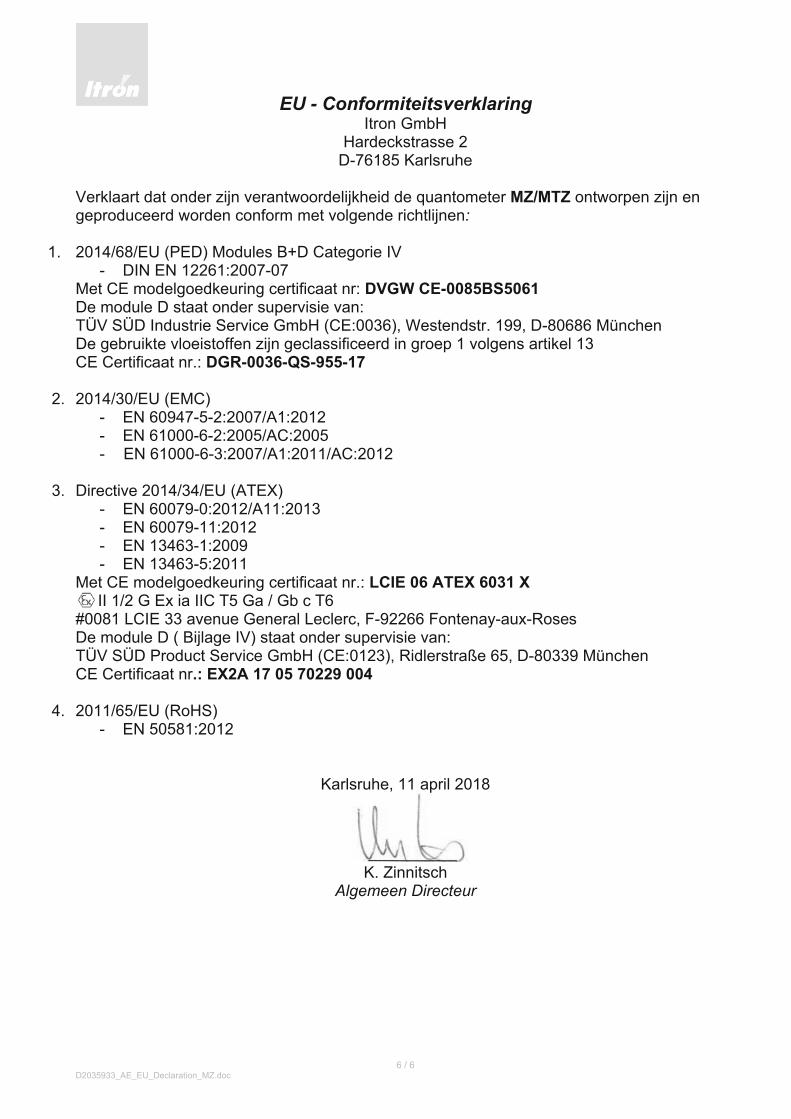
Verklaart dat onder zijn verantwoordelijkheid de quantometer MZ/MTZ ontworpen zijn en geproduceerd worden conform met volgende richtlijnen:
1. 2014/68/EU (PED) Modules B+D Categorie IV
- DIN EN 12261:2007-07 Met CE modelgoedkeuring certificaat nr: DVGW CE-0085BS5061De module D staat onder supervisie van: TÜV SÜD Industrie Service GmbH (CE:0036), Westendstr. 199, D-80686 München De gebruikte vloeistoffen zijn geclassificeerd in groep 1 volgens artikel 13 CE Certificaat nr.: DGR-0036-QS-955-17
2. 2014/30/EU (EMC)
- EN 60947-5-2:2007/A1:2012 - EN 61000-6-2:2005/AC:2005 - EN 61000-6-3:2007/A1:2011/AC:2012
3. Directive 2014/34/EU (ATEX) - EN 60079-0:2012/A11:2013 - EN 60079-11:2012 - EN 13463-1:2009 - EN 13463-5:2011
Met CE modelgoedkeuring certificaat nr.: LCIE 06 ATEX 6031 X II 1/2 G Ex ia IIC T5 Ga / Gb c T6 #0081 LCIE 33 avenue General Leclerc, F-92266 Fontenay-aux-Roses De module D ( Bijlage IV) staat onder supervisie van: TÜV SÜD Product Service GmbH (CE:0123), Ridlerstraße 65, D-80339 München CE Certificaat nr.: EX2A 17 05 70229 004
4. 2011/65/EU (RoHS)
- EN 50581:2012
Karlsruhe, 11 april 2018
K. Zinnitsch
Algemeen Directeur

33
1 Kenmerken . . . . . . . . . . . . . . . . . . . . . . . . . . . . . . . . . . . . . . . . . . . . . . . . . . . . . . . . . . . .33
2 OntvangstvandeMZ . . . . . . . . . . . . . . . . . . . . . . . . . . . . . . . . . . . . . . . . . . . . . . . . . . .33 2 .1 Verpakking . . . . . . . . . . . . . . . . . . . . . . . . . . . . . . . . . . . . . . . . . . . . . . . . . . . . . . . . .33 2 .2 OpslagStorage . . . . . . . . . . . . . . . . . . . . . . . . . . . . . . . . . . . . . . . . . . . . . . . . . . . . . .33 2 .3 Behandeling . . . . . . . . . . . . . . . . . . . . . . . . . . . . . . . . . . . . . . . . . . . . . . . . . . . . . . . .33
3 Installatie . . . . . . . . . . . . . . . . . . . . . . . . . . . . . . . . . . . . . . . . . . . . . . . . . . . . . . . . . . . . . . .33 3 .1 Algemeneopmerkingen . . . . . . . . . . . . . . . . . . . . . . . . . . . . . . . . . . . . . . . . . . . . .33 3 .2 Aanbevoleninstallatie . . . . . . . . . . . . . . . . . . . . . . . . . . . . . . . . . . . . . . . . . . . . . . .34 3 .3 Opstarten . . . . . . . . . . . . . . . . . . . . . . . . . . . . . . . . . . . . . . . . . . . . . . . . . . . . . . . . . .34 3 .3 .1 Installatiemeteenklepaandeinlaatzijde . . . . . . . . . . . . . . . . . . . . . .34 3 .3 .2 Installatievankleppenindeinlaatofuitlaatleiding . . . . . . . . . . . . . .34 3 .3 .3 Installatievankleppenindeinlaatofuitlaatleiding . . . . . . . . . . . . . .34
4 Connectoren . . . . . . . . . . . . . . . . . . . . . . . . . . . . . . . . . . . . . . . . . . . . . . . . . . . . . . . . . . .34
5 Onderhoud . . . . . . . . . . . . . . . . . . . . . . . . . . . . . . . . . . . . . . . . . . . . . . . . . . . . . . . . . . . .35 5 .1 Smering . . . . . . . . . . . . . . . . . . . . . . . . . . . . . . . . . . . . . . . . . . . . . . . . . . . . . . . . . . .35 5 .2 Externvochtfilter . . . . . . . . . . . . . . . . . . . . . . . . . . . . . . . . . . . . . . . . . . . . . . . . . . . .35 5 .3 Inspektieenreparatie . . . . . . . . . . . . . . . . . . . . . . . . . . . . . . . . . . . . . . . . . . . . . . .35
6 TechnischeInformatie . . . . . . . . . . . . . . . . . . . . . . . . . . . . . . . . . . . . . . . . . . . . . . . . . .37
DU
TCH

34
Houdtditinstallatie-voorschrifttoegankelijkvoorallegebruikers .
Respecteerallenationaleregelstavinstallatie,bedieningenservicevandegasmeters .
1 KenmerkenTurbinegasmeterszijnstromingsmeters .Degasstroomdrijfthetturbinewielaanenderotatiesnelheidvanhetturbinewielispro-portioneelmetdelineairesnelheidvanhetgas .Dezeomwentelingenwordenmecha-nisch doorgegeven aan het telwerk dooreenmagnetischekoppeling .
Voorgedetaileerdeinformatiezie:Annex1 .
2 Ontvangst van de MZ
2.1 VerpakkingIederemeter,afhankelijkvanhettype,wordtgeleverdineenapartedoosofopeenhou-tenpallet .Deverpakkingbevateencontraconnectorvoordegeinstalleerdereedcon-tacten enolie in geval dat een oliepompgeinstalleerdis .
2.2 Opslag StorageIndien de meter niet direkt gebruiktwordt,moet deze worden opgeslagen ineenschoneendrogeomgeving .Deafsluit-doppenopinlaatenuitlaatzijdevandeme-terdienenpasbij installatievandemeterverwijderdteworden .Opslagtemperatuur:-40°Cto+70°C
2.3 BehandelingDemetersmoetenmetzorgwordenbehan-deld .Ophijsenvandemeteralleenmethijs-bandenomde„body“ofaandehijsogen .
3 Installatie
3.1 Algemene opmerkingen ZieAnnex2enPEDinformatieinAnnex6
•DestandaardMZisontworpenvoorhetmeten van schone en niet aggressievegassoorten .Voorhetmetenvanaggres-sieve gassen gaarne contact opnemenmet Itron voor informatie over specialeuitvoeringen .
•Indien de meter is uitgevoerd met eenoliepomp,dient het oliereservoir aange-pasttezijnaandemeterpositie .
•(1)Voorinstallatiedemetercontrolerenop eventuele beschadigingen ,ontstaantijdenstransport .
•(2)Nietlassenaanhetleidingwerkbijeengeinstalleerdemeter .
•(3)Demetermoettenallentijde,span-ningsvrijgeinstalleerdworden .Deflenzenmoetengoeduitgelijndworden .Hetmax .aanhaalmomentvandeboutenmagdeintabelvermeldewaardennietoverschrij-den(Nm):
M16 M2085 170
Boutengelijkmatig ,bijvoorkeurruislings,aandraaien .
•(4) Om de nauwkeurigheid tewaarborgen,dientdemetergeinstalleerdtewordenmeteen recht inlaatpijpstukvan3DN .
•(5) Impulsgever aansluiting: Gasmetersworden vaak geinstalleerd in gebiedenmeteengasrisiko .Daarommoetdeelek-trische verbinding met de gasmeter Exgemarkeerdzijnofvoldoenaaneenge-lijkwaardigetoelating .Deconnectoraan-sluiting en de pulswaardes staan op detelwerkplaat .

35
•(6)Vervuilinginhetgaszoalsbvzandenlaskorrelskunnenhetturbinewielbescha-digen .Hetgebruikvaneenzeefoffilterwordtdringendaanbevolen .
•(7)Drukpulsenmoetentijdenshetopstar-tenvoorkomenworden,ditomhetturbi-newieltebeschermen .Omschadebijhetopstartentevoorkomen,dientdedrukver-hoginglangszaammetnietmeerdan0,3barpersecondeplaatstevinden .
3.2 Aanbevolen installatie.Turbinemeters zijn „stromingsmeters“ ditbetekend dat de metrologie beinvloedtkanwordendoorverstoringen,veroorzaaktdoordegasstroom .
Eenhogeremeetnauwkeurigheidkanver-kregenwordendoordevolgenderegelstehanteren:
•Gebruik bij voorkeur bochtstukken meteengroteradius(>5DN)aandeinlaat-zijdevandemeter .
•Bij diameter variaties, svp altijd con-vigerend , divigerende pijpstukkengebruiken,voorkomhetgebruikvanver-schillendediameters .
•Obstakel,zoalszakuizen,mogennietuit-stekenbinneneenafstandvan2DNindeaanstroomzijdevandemeter .
•Pakkingenmoetenmoetenopde juistewijze(centrisch)wordengemonteerdenmoetennietuitstekenindeleiding .
3.3 Opstarten
3.3.1 Installatie met een klep aan de in-laatzijde
Opendekleperglangszaamtotdatdeme-terbeginttelopen .Voerlangszaamdedrukopindeuitlaatzijde(max .0,3bar/sec) .Alsdedrukaandeuitlaatzijdeisgestabiliseerd,opendeklepvolledig .
3.3.2 Installatie van kleppen in de inlaat of uitlaat leiding
Sluit de klep indeuitlaatleiding . Opendeklepindeinlaatleidinglangszaam(max .0,3bar/sec) .Alsdedrukindemeterisgesta-biliseerd,opendanlangszaamdeklepaandeuitlaatzijdeomdedruk indemeter tehandhavenenoverbelastingtevoorkomen .
3.3.3 Installatie met een by-pass.Sluitallekleppen .Langszaamdeby-passopenenenwachtentotdeuitlaatdrukisge-stabiliseerd .Vervolgdanals3 .3 .2 .Sluitdebypass .
4 ConnectorenDe MZ kan optioneel uitgevoerd wordenmet2LaagFrequent(LF),Reedcontacteneneenanti-fraudeschakelaar;meteenin-duktiefmiddelofhoogfrequent(HF)puls-contact .EenCyblesensorkanookophettelwerkaangebrachtworden,zieAnnex3 .Opmerkingenvoorhetgebruikinmogelijkexplosieveomgeving(ATEX):•Puls contactenmogenalleenaangeslo-
tenwordenopintrinsiekveiligesystemen,conformEN60079-11 .
•Gebruikalleeneenvochtigedoekomdetegenkoptereinigen .
•Alseendunlaagjeroestvormingmogelijkis(zwevendroestindedirekteomgevingvan de meter), moeten alle uitwendigealuminium delen dienovereenkomstigwordenbeschermd(b .v .meteenverni-slaag) .
•Demeterdientgeaardteworden•Voor installatie,demontageof reparatie
vandemeterop lokatie,alleengereed-schapgebruikenwatistoegestaanvoorexplosieveomgeving .
•Demetermagnietblootgesteldwordenaan:vuur,stralingofgeluidsgolven .
Voorpulsewaardenenmaximalefrequen-tieszieAnnex1 .
DU
TCH

Voor electrische gegevens en connectoraansluitingenAnnex4 .Debedradingvandecontactenstaatvermeldophetnaam-plaatjevandemeter .
5 OnderhoudAlsdemeteropdejuistewijzeisgeinstal-leerdeningebruikgenomen,heeftdeMZgeen speciale aandacht nodig en garan-deerd een jarenlange goede werking .3 .4Smering
5.1 SmeringMetersvoorzienvaneenoliepompmoetenperiodiekgesmeerdworden .
Oliewordtmetdemetermeegeleverd .Ermoetspecialeoliegebruiktwordenbv:
–Aeroshellfluid12MIL6085A–IsoflexPDP38(Klüber)–Anderol401D(MobilOil)–UnivisP38(Shell)
Hoeveelheidoliepertype:
d)Permetertypedientdeindetabelaan-gegevenoliehoeveelheid gevuld tewor-den .
DN Oilievol .(cm3) Slagvolume50/80 4 20100 5 25
150/200 6 30
e)Bijservice
DN Oilievol .(cm3) Slagvolume
50/80 0,5 2-3100 0,8 4
150/200 1,0 5
f)Aanbevolensmeringsperiode
Toepassing smeerperiode
Drooggas,geenvuil 6maanden
Gasmetweinig Maandelijkscondensaatenweinigstof
Gasmeteenhoog Wekelijkspercentagecondensaatenstof .BIOGAS toepassingen
5.2 Extern vochtfilter Demeterkanuitgevoerdwordenmeteen(opschroefbaar)externvochtfiltervoorin-stallatie indebuitenlucht .Het filtermoetvervangen worden als de kleur is veran-derd .Isdathetgeval,schroefdeoudelosenschroefdenieuweophettelwerk .
5.3. Inspektie en reparatieHetismogelijkomdeFluxi2000/TZtecon-trolerenopgoedewerkingdooreenzg„spin-test“uittevoeren .Dezetestgeeftinformatieovereventuelewrijvingvandelagers .
Detestgaatalsvolgt:
•Turbinewiellatendraaienop30tot50%vanQmaxenmeetdetijdtothetturbi-newielstopt .
•VergelijkdezetijdmetdeaangegeventijdinAnnex5 .
Devolgenderegelsgeldeningevalvanre-paratie:
•Reparaties moeten uitgevoerd wordendoor deskundig personeel . Naderhanddient een dichtheid test uitgevoerd teworden1,1xPS(Pmax) .
•Bij vervangingvandruklagers,altijd con-troleren of de juiste reservedelen con-formdePEDgebruiktworden .
•Ingevalvaneennatgas,kanzowelinternalsexterncorrosieontstaan .Vervangdemeter .
•Gebruikvetenalcoholvrijereinigingspro-ducten
36

37
Annex 1: Characteristics / Caractéristiques / Technische Daten / Caratteristiche tecniche / Caracteristicas / Technische informatie
8
Déclaration de Conformité CE Itron GmbH
Hardeckstrasse 2 D-76185 Karlsruhe
Déclare que le produit est conçu et fabriqué en conformité avec les Directives suivantes :
1. 97/23/CE Modules B+D Catégorie IV - DESP Avec certificat dʼapprobation de type n° : DVGW CE-0085BS5061Le module D est supervisé par : TÜV SÜD Industrie Service GmbH (CE:0036); Westendstr. 199, D-80686 München Certificat CE n° : DGR-0036-QS-955-14
2. 2004/108/CE – Directive EMC Le produit est conforme à la Directive 2004/108/EC par le fait qu´il satisfait aux normes suivantes : EN 61000-6-2 (2006); EN 61000-6-3 (2007); EN 60947-5-6 (2000).
3. 94/9/CE – Directive ATEX Avec certificat dʼapprobation de type n° : LCIE 06 ATEX 6031 X#0081 LCIE 33 avenue General Leclerc, F-92266 Fontenay-aux-Roses II 1 G ou II 1/2 G Ex ia IIC T5 c T6 Le produit est conforme aux normes suivantes : EN 60079-0:2012 + A11:2013, EN 60079-11:2012, EN 13463-1:2009, EN 13463-5:2011.Le module D (Annexe IV) est supervisé par : TÜV SÜD Product Service GmbH (CE:0123) Ridlerstraße 65, D-80339 München Certificat CE n° : EX2 14 05 70229 003
Karlsruhe, 08.10.2015
__________________ P. Garcia
Responsable de production
37
Annex 1: Characteristics / Caractéristiques / Technische Daten / Caratteristiche tecniche / Caracteristicas / Technische informatie
With correction gears 32/40 (correction 0%)
DN(mm)
Max Flow (m3/h)
Min Flow (m3/h)
Pressure loss (mbar)
� = 0,8Kg/m3
1 Imp LF &Cyble
(m3/Imp)
Freq LF Qmax (Hz)
1 Imp MF (dm3/Imp)
Freq MF Qmax (Hz)
1 Imp HF (dm3/Imp)
Freq HF Qmax (Hz)
RPM Qmax (Rot / min)
V PED(dm3)
50 100 6 8,1 0,1 0,28 5,27660 5,26 0,00868 3200 15999 0,1
80 160250400
101625
2,04,8
11,0
1 0,040,070,11
23,0769223,0769239,11111
1,933,012,84
0,037970,037970,06434
117118291727
585391468634
0,5
100 250400650
162540
2,04,8
11,0
1 0,070,110,18
23,0769223,0769239,11111
3,014,814,62
0,062710,062710,10628
110717721699
415366446371
1,1
150 65010001600
4065
100
1,54,39,0
1 0,180,280,44
23,0769223,0769239,11111
7,8212,0411,36
0,153850,153850,26074
117418061705
352154175114
3,6
200 100016002500
65100160
1,54,39,0
10 0,030,040,07
230,7692230,7692391,1111
1,21,931,78
0,376610,376610,63829
73811801088
221335403264
7,3
Dimensions (mm) and weights
ISO PN 10 – ISO PN 40 / ANSI 150
DN L A B C D E Kg
50 60 15 18 156 160 163 4
80 120 35 34 173 180 176 10
ISO PN 10 – ISO PN 16 / ANSI 150
100 150 54 28 209 180 186 19
150 200 71 48 238 225 216 33
200 200 69 43 273 250 277 85
DU
TCH
With correction gears 32/40 (correction 0%)
DN(mm)
Max Flow (m3/h)
Min Flow (m3/h)
Pressure loss (mbar)
= 0,8Kg/m3
1 Imp LF &Cyble
(m3/Imp)
Freq LF Qmax (Hz)
1 Imp MF (dm3/Imp)
Freq MF Qmax (Hz)
1 Imp HF (dm3/Imp)
Freq HF Qmax (Hz)
RPM Qmax (Rot / min)
V PED(dm3)
50 100 6 8,1 0,1 0,28 5,27660 5,26 0,00868 3200 15999 0,1
80 160250400
101625
2,04,8
11,0
1 0,040,070,11
23,0769223,0769239,11111
1,933,012,84
0,037970,037970,06434
117118291727
585391468634
0,5
100 250400650
162540
2,04,8
11,0
1 0,070,110,18
23,0769223,0769239,11111
3,014,814,62
0,062710,062710,10628
110717721699
415366446371
1,1
150 65010001600
4065
100
1,54,39,0
1 0,180,280,44
23,0769223,0769239,11111
7,8212,0411,36
0,153850,153850,26074
117418061705
352154175114
3,6
200 100016002500
65100160
1,54,39,0
10 0,030,040,07
230,7692230,7692391,1111
1,21,931,78
0,376610,376610,63829
73811801088
221335403264
7,3
Dimensions(mm)andweights
ISOPN10–ISOPN40/ANSI150
DN L A B C D E Kg
50 60 15 18 156 160 163 4
80 120 35 34 173 180 176 10
ISOPN10–ISOPN16/ANSI150
100 150 54 28 209 180 186 19
150 200 71 48 238 225 216 33
200 200 69 43 273 250 277 85
DU
TCH

38
ANNEX 2: General recommendations

39
3xD(min)
3
3
3
3
3

40
5

41
6
Qstart ≤ Qmax

42
7
8

43
ANNEX 3: Installation of the Cyble sensor
1)Mounting 2)Screwing(Maxtorque:0,25Nm)3)Sealing
ANNEX 4: Transmitters characteristics and plugging
Unlessonthenameplatenotedthefollowingelectricalparametershallbeconsidered:
Low Frequency Transmitter (reed contact) High & Medium Frequency Transmitter (inductive)
Characteristics For Non ATEX pro-ducts
For ATEX products **intrinsically safe circuits EN 60079-0/-11
For ATEX products ***intrinsically safe circuits EN 60079-0/-11
Powerrating Max .10W Max .120mW Max .64mWVoltage(Break-down) Max .180Vdc Max .15Vdc Max .15VdcCurrent(Switching) Max .50mA Max .50mA Max .50mACapacitanceandInductance C=0F,L=0H C=0F,L=0H C=90ƞF,L=250µHOperationtemperaturerange -30°Cto+60°C -30°Cto+60°C -30°Cto+60°C
** FollowingrecommendvaluesLowFrequencyPulseTransmittersdonothaveanypotentialsourcesofignitionandshallbenotmarkedaccordingtodirective2014/34/EU .ThedeviceisfreetobeusedinATEXareaasitisasimpleapparatusasdefinedinEN60079-11§5 .7 .
*** ProximitydetectorsconformtoEN60947-5-6(NAMUR)standard .
Characteristics Low Frequency Transmitter (Cyble Module)
Contactpowerrating Max .1WVoltage(Break-down) Max .14 .3VdcCurrent(Switching) Max .50mAOperationtemperaturerange -25°Cto+55°C
Pluggingofthemeter(externviewofthesocketinstalledonthemeter) LF,MF HF DIN45322 DIN41524

ANNEX 5: Spin test time
ANNEX 6: PED information
DN MinimumstartingSpeed(RPM)
MaximumstartingSpeedRPM)
SpinTime(seconds)„TypicalST“
Platicturbinewheel Aluturbinewheel
50 5000 8000 60 70
80 3000 5000 70 100
100 2000 3000 130 190
150 2000 3000 170 240
200 1000 2000 170 240
ISOPN10 ISOPN16ISOPN20ANSI150
ISOPN25 ISOPN40
PS(bar) 10 16 19,3 25 40
PT(bar) 15 24 30 38 60
TS=-30°Cto+60°C/VolumePED:seeAnnex1
Itron GmbH
Hardeckstraße2
76185Karlsruhe
info .karlsruhe@itron .com·www .itron .com
Tel. +4972159810
Fax +497215981189
BR
-10
14
-M
Z07
.19
-m
edia
logi
k/2
00
0St
-©
Cop
yrig
ht2
019
,Itr
on,A
llR
ight
sR
eser
ved .