Embed Size (px)
Citation preview
1 2017-03-15 issue 4Data is only for informational purpose. All specifications are subject to change without notice.
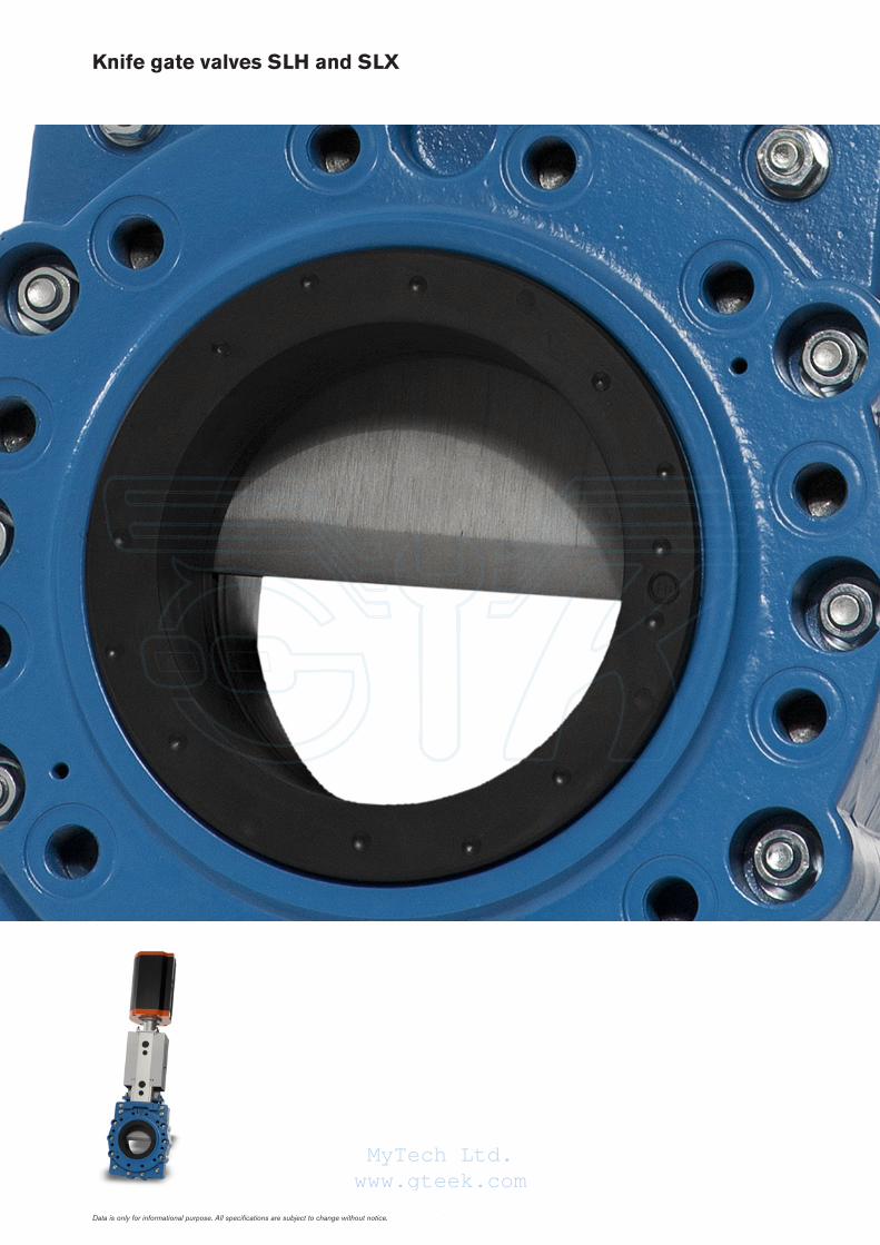
Knife gate valves SLH and SLX
MyTech Ltd.www.gteek.com
2
1
2
3
54
7
6
2017-03-15 issue 4
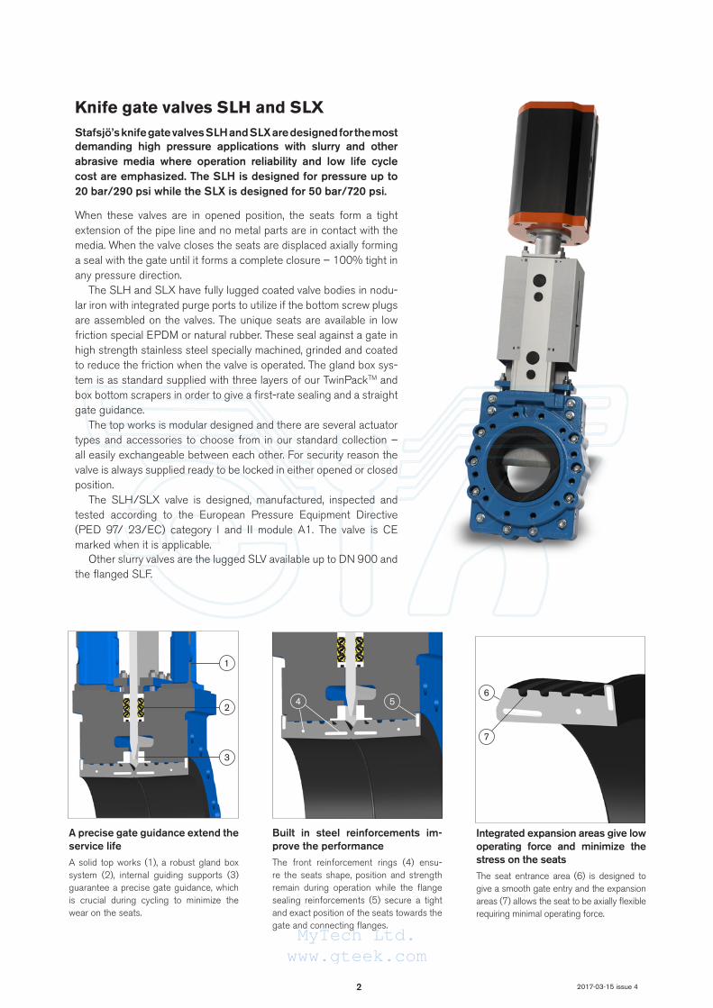
Knife gate valves SLH and SLXStafsjö’s knife gate valves SLH and SLX are designed for the most demanding high pressure applications with slurry and other abrasive media where operation reliability and low life cycle cost are emphasized. The SLH is designed for pressure up to 20 bar/290 psi while the SLX is designed for 50 bar/720 psi.
When these valves are in opened position, the seats form a tight extension of the pipe line and no metal parts are in contact with the media. When the valve closes the seats are displaced axially forming a seal with the gate until it forms a complete closure – 100% tight in any pressure direction.
The SLH and SLX have fully lugged coated valve bodies in nodu-lar iron with integrated purge ports to utilize if the bottom screw plugs are assembled on the valves. The unique seats are available in low friction special EPDM or natural rubber. These seal against a gate in high strength stainless steel specially machined, grinded and coated to reduce the friction when the valve is operated. The gland box sys-tem is as standard supplied with three layers of our TwinPackTM and box bottom scrapers in order to give a first-rate sealing and a straight gate guidance.
The top works is modular designed and there are several actuator types and accessories to choose from in our standard collection – all easily exchangeable between each other. For security reason the valve is always supplied ready to be locked in either opened or closed position.
The SLH/SLX valve is designed, manufactured, inspected and tested according to the European Pressure Equipment Directive (PED 97/ 23/EC) category I and II module A1. The valve is CE marked when it is applicable.
Other slurry valves are the lugged SLV available up to DN 900 and the flanged SLF.
A precise gate guidance extend the service lifeA solid top works (1), a robust gland box system (2), internal guiding supports (3) guarantee a precise gate guidance, which is crucial during cycling to minimize the wear on the seats.
Built in steel reinforcements im-prove the performanceThe front reinforcement rings (4) ensu-re the seats shape, position and strength remain during operation while the flange sealing reinforcements (5) secure a tight and exact position of the seats towards the gate and connecting flanges.
Integrated expansion areas give low operating force and minimize the stress on the seatsThe seat entrance area (6) is designed to give a smooth gate entry and the expansion areas (7) allows the seat to be axially flexible requiring minimal operating force.
MyTech Ltd.www.gteek.com

3 2017-03-15 issue 4
Design data
Sizes Flange drilling Face-to-face dimension Corrosion protection
DN 80 - DN 450 EN 1092 PN20EN 1092 PN25EN 1092 PN40EN 1092 PN50ASME/ANSI B16.5 Class 150ASME/ANSI B16.5 Class 300AS 2129 Table F/H
Stafsjö manufacturing standard
Non-corrosive resistant materials are coated in colour RAL5015 acc. to Stafsjö’s standard, which fulfill the requirements in EN ISO 12944 class C3.
Other sizes, flange drillings, ATEX zones and corrosion protection on request.
Leakage rate Pressure tests
EN 12266-1:2009 Rate A: no visually detectable leakage is allowed for duration of the test.
Pressure tests are performed with water at 20º C according to EN 12266-1:2009.Pressure shell test: 1,5 times maximum allowable working pressure for open valve.Pressure seat tightness test: 1,1 times maximum allowable differential pressure for closed valve.
Maximum working pressure body at 20°C Maximum differential pressure at 20°C
Valve type and sizes bar Valve type and sizes bar
SLH DN 80 - DN 450 20 SLH DN 80 - DN 450 20
SLX DN 80 - DN 450 50 SLX DN 80 - DN 450 50
Basic equipment
A. Valve Body
Material Code Type Maximum temperature °C
Nodular iron (L) 5.3105 (JS1020) 200
The valve body is as standard supplied with purge ports: DN 80-DN 150: 3/4” - 1/2”, DN 200: 3/4”, DN 250: 3/4” - 1”, DN 300: 1”, DN 350 1” - 1 1/4”, DN 400 - DN 450: 1 1/4”
B. Gate
Valve type Material Type Surface treatment
SLH Duplex stainless steel EN 1.4462 (S32205) Hard anti-stick coated
SLX Stainless steel EN 1.4542 (S17400/17-4PH) Hard anti-stick coated
Other materials on request
C. Seats
Material Code Maximum temperature °C
Natural rubber (NR) 80
EPDM (E) 120
D. Box packing
Material Code Maximum temperature °C
TwinPackTM with scrapers in UHMWPE (TY) 80
Actuators
Manual Code Automatic Code
Hand wheel (HWR) Electrical motor (EM)
Bevel gear (BG) Hydraulic cylinder (MH)
Double-acting
pneumatic cylinder
(EC)
The actuators are described in separate data sheets. For information on the sizing for each valve size or information on other actuators or ATEX- classified ones, please contact Stafsjö or your local representative.
MyTech Ltd.www.gteek.com
4 2017-03-15 issue 4
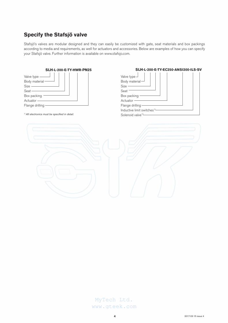
Specify the Stafsjö valve
Stafsjö’s valves are modular designed and they can easily be customized with gate, seat materials and box packings according to media and requirements, as well for actuators and accessories. Below are examples of how you can specify your Stafsjö valve. Further information is available on www.stafsjo.com.
1) All electronics must be specified in detail.
Valve type Body materialSizeSeatBox packingActuatorFlange drilling
Valve typeBody materialSizeSeatBox packingActuatorFlange drillingInductive limit switches1)
Solenoid valve1)
SLH-L-200-E-TY-EC250-ANSI300-ILS-SVSLH-L-200-E-TY-HWR-PN25
MyTech Ltd.www.gteek.com
5 2017-03-15 issue 4
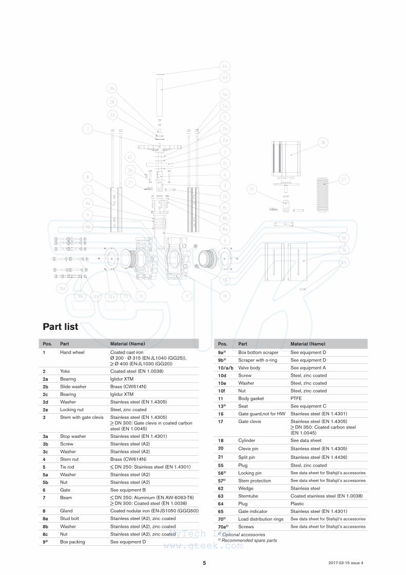
Part list
Pos. Part Material (Name)
1 Hand wheel Coated cast ironØ 200 - Ø 315 (EN-JL1040 (GG25)), > Ø 400 (EN-JL1030 (GG20))
2 Yoke Coated steel (EN 1.0038)
2a Bearing Iglidur XTM
2b Slide washer Brass (CW614N)
2c Bearing Iglidur XTM
2d Washer Stainless steel (EN 1.4305)
2e Locking nut Steel, zinc coated
3 Stem with gate clevis Stainless steel (EN 1.4305)> DN 300: Gate clevis in coated carbon steel (EN 1.0045)
3a Stop washer Stainless steel (EN 1.4301)
3b Screw Stainless steel (A2)
3c Washer Stainless steel (A2)
4 Stem nut Brass (CW614N)
5 Tie rod < DN 250: Stainless steel (EN 1.4301)
5a Washer Stainless steel (A2)
5b Nut Stainless steel (A2)
6 Gate See equipment B
7 Beam < DN 250: Aluminium (EN AW-6063-T6)> DN 300: Coated steel (EN 1.0038)
8 Gland Coated nodular iron (EN-JS1050 (GGG50))
8a Stud bolt Stainless steel (A2), zinc coated
8b Washer Stainless steel (A2), zinc coated
8c Nut Stainless steel (A2), zinc coated
93) Box packing See equipment D
Pos. Part Material (Name)
9a3) Box bottom scraper See equipment D
9b3) Scraper with o-ring See equipment D
10/a/b Valve body See equipment A
10d Screw Steel, zinc coated
10e Washer Steel, zinc coated
10f Nut Steel, zinc coated
11 Body gasket PTFE
133) Seat See equipment C
16 Gate guard,not for HW Stainless steel (EN 1.4301)
17 Gate clevis Stainless steel (EN 1.4305)> DN 350: Coated carbon steel (EN 1.0045)
18 Cylinder See data sheet
20 Clevis pin Stainless steel (EN 1.4305)
21 Split pin Stainless steel (EN 1.4436)
55 Plug Steel, zinc coated
562) Locking pin See data sheet for Stafsjö’s accessories
572) Stem protection See data sheet for Stafsjö’s accessories
62 Wedge Stainless steel
63 Stemtube Coated stainless steel (EN 1.0038)
64 Plug Plastic
65 Gate indicator Stainless steel (EN 1.4301)
702) Load distribution rings See data sheet for Stafsjö’s accessories
70a2) Screws See data sheet for Stafsjö’s accessories
2) Optional accessories3) Recommended spare parts
MyTech Ltd.www.gteek.com
6
J
H
L
K
E
AC
B
D
B
FG
C
6, 7 8
4, 5
9 10
2017-03-15 issue 4
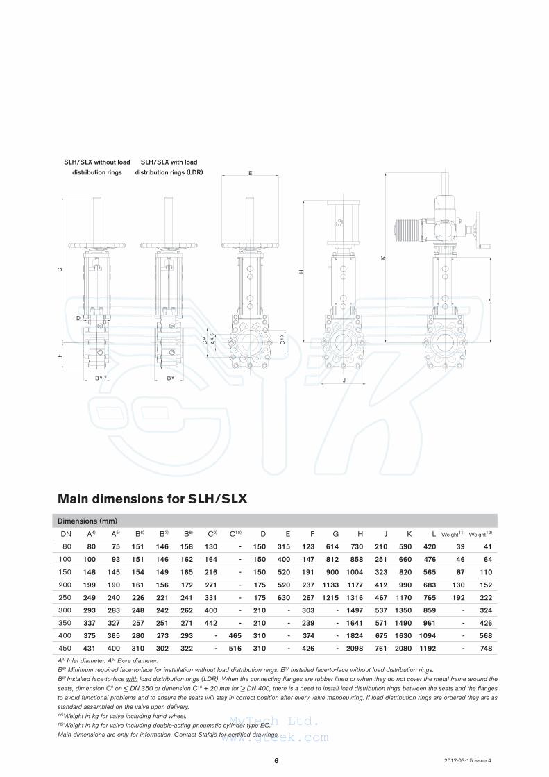
Main dimensions for SLH/SLX
Dimensions (mm)
DN A4) A5) B6) B7) B8) C9) C10) D E F G H J K L Weight11) Weight12)
80 80 75 151 146 158 130 - 150 315 123 614 730 210 590 420 39 41
100 100 93 151 146 162 164 - 150 400 147 812 858 251 660 476 46 64
150 148 145 154 149 165 216 - 150 520 191 900 1004 323 820 565 87 110
200 199 190 161 156 172 271 - 175 520 237 1133 1177 412 990 683 130 152
250 249 240 226 221 241 331 - 175 630 267 1215 1316 467 1170 765 192 222
300 293 283 248 242 262 400 - 210 - 303 - 1497 537 1350 859 - 324
350 337 327 257 251 271 442 - 210 - 239 - 1641 571 1490 961 - 426
400 375 365 280 273 293 - 465 310 - 374 - 1824 675 1630 1094 - 568
450 431 400 310 302 322 - 516 310 - 426 - 2098 761 2080 1192 - 748
A4) Inlet diameter. A5) Bore diameter. B6) Minimum required face-to-face for installation without load distribution rings. B7) Installed face-to-face without load distribution rings. B8) Installed face-to-face with load distribution rings (LDR). When the connecting flanges are rubber lined or when they do not cover the metal frame around the seats, dimension C9 on < DN 350 or dimension C10 + 20 mm for > DN 400, there is a need to install load distribution rings between the seats and the flanges to avoid functional problems and to ensure the seats will stay in correct position after every valve manoeuvring. If load distribution rings are ordered they are as standard assembled on the valve upon delivery. 11)Weight in kg for valve including hand wheel.12)Weight in kg for valve including double-acting pneumatic cylinder type EC.Main dimensions are only for information. Contact Stafsjö for certified drawings.
SLH/SLX without load
distribution rings
SLH/SLX with load
distribution rings (LDR)
MyTech Ltd.www.gteek.com
7
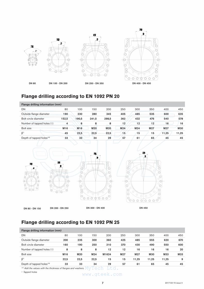
DN 80 DN 100 - DN 200 DN 400 - DN 450DN 250 - DN 350
DN 80 - DN 150 DN 200 - DN 250 DN 300 - DN 400 DN 450
2017-03-15 issue 4
Flange drilling according to EN 1092 PN 25
Flange drilling information (mm)
DN 80 100 150 200 250 300 350 400 450
Outside flange diameter 200 235 300 360 425 485 555 620 670
Bolt circle diameter 160 190 250 310 370 430 490 550 600
Number of tapped holes (○) 8 8 8 12 12 16 16 16 20
Bolt size M16 M20 M24 M1624 M27 M27 M30 M33 M33
β° 22,5 22,5 22,5 15 15 11,25 11,25 11,25 9
Depth of tapped holes13) 33 33 34 29 57 61 65 45 4513) Add the values with the thickness of flanges and washers.○ Tapped holes
Flange drilling according to EN 1092 PN 20
Flange drilling information (mm)
DN 80 100 150 200 250 300 350 400 450
Outside flange diameter 190 230 280 345 405 485 535 600 635
Bolt circle diameter 152,5 190,5 241,5 298,5 362 432 476 540 578
Number of tapped holes (○) 4 8 8 8 12 12 12 16 16
Bolt size M16 M16 M20 M20 M24 M24 M27 M27 M30
β° 45 22,5 22,5 22,5 15 15 15 11,25 11,25
Depth of tapped holes13) 33 33 34 29 57 61 65 45 45
MyTech Ltd.www.gteek.com

8
DN 80 - DN 150 DN 200 - DN 250
DN 80 - DN 100 DN 150 - DN 200 DN 450DN 350 - DN 400
DN 450DN 300 - DN 400
DN 250 - DN 300
2017-03-15 issue 4
Flange drilling according to EN 1092 PN 40
Flange drilling information (mm)
DN 80 100 150 200 250 300 350 400 450
Outside flange diameter 200 235 300 375 450 515 580 660 685
Bolt circle diameter 160 190 250 320 385 450 510 585 610
Number of tapped holes (○) 8 8 8 12 12 16 16 16 20
Bolt size M16 M20 M24 M27 M30 M30 M33 M36 M36
β° 22,5 22,5 22,5 15 15 11,25 11,25 11,25 9
Depth of tapped holes13) 33 33 34 29 57 61 65 45 45
Flange drilling according to EN 1092 PN 50
Flange drilling information (mm)
DN 80 100 150 200 250 300 350 400 450
Outside flange diameter 210 255 320 380 445 520 585 650 710
Bolt circle diameter 168,5 200 270 330 387,5 451 514,5 571,5 629
Number of tapped holes (○) 8 8 12 12 16 16 20 20 24
Bolt size M20 M20 M20 M24 M27 M30 M30 M33 M33
β° 22,5 22,5 15 15 11,25 11,25 9 9 7,5
Depth of tapped holes13) 33 33 34 29 57 61 65 45 4513) Add the values with the thickness of flanges and washers.○ Tapped holes
MyTech Ltd.www.gteek.com
9
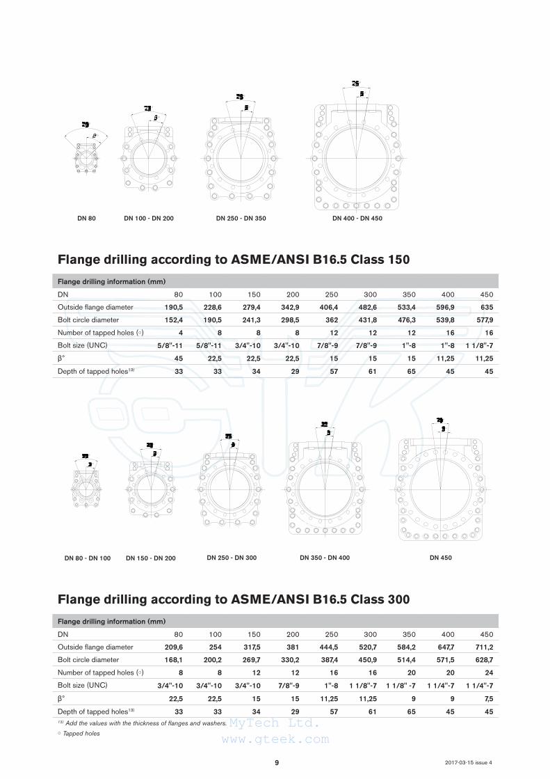
DN 80 DN 100 - DN 200 DN 250 - DN 350 DN 400 - DN 450
DN 80 - DN 100 DN 150 - DN 200 DN 350 - DN 400DN 250 - DN 300 DN 450
2017-03-15 issue 4
Flange drilling according to ASME/ANSI B16.5 Class 150
Flange drilling information (mm)
DN 80 100 150 200 250 300 350 400 450
Outside flange diameter 190,5 228,6 279,4 342,9 406,4 482,6 533,4 596,9 635
Bolt circle diameter 152,4 190,5 241,3 298,5 362 431,8 476,3 539,8 577,9
Number of tapped holes (○) 4 8 8 8 12 12 12 16 16
Bolt size (UNC) 5/8"-11 5/8"-11 3/4"-10 3/4"-10 7/8"-9 7/8"-9 1"-8 1"-8 1 1/8"-7
β° 45 22,5 22,5 22,5 15 15 15 11,25 11,25
Depth of tapped holes13) 33 33 34 29 57 61 65 45 45
Flange drilling according to ASME/ANSI B16.5 Class 300
Flange drilling information (mm)
DN 80 100 150 200 250 300 350 400 450
Outside flange diameter 209,6 254 317,5 381 444,5 520,7 584,2 647,7 711,2
Bolt circle diameter 168,1 200,2 269,7 330,2 387,4 450,9 514,4 571,5 628,7
Number of tapped holes (○) 8 8 12 12 16 16 20 20 24
Bolt size (UNC) 3/4"-10 3/4"-10 3/4"-10 7/8"-9 1"-8 1 1/8"-7 1 1/8" -7 1 1/4"-7 1 1/4"-7
β° 22,5 22,5 15 15 11,25 11,25 9 9 7,5
Depth of tapped holes13) 33 33 34 29 57 61 65 45 4513) Add the values with the thickness of flanges and washers.○ Tapped holes
MyTech Ltd.www.gteek.com

10
DN 80 - DN 100 DN 150 - DN 250 DN 300 - DN 350 DN 450
DN 80 - DN 100 DN 150 - DN 250 DN 300 - DN 350 DN 450
2017-03-15 issue 4
Flange drilling according to AS Table F
Flange drilling information (mm)
DN 80 100 150 200 250 300 350 400 450
Outside flange diameter 205 230 305 370 430 490 550 610 675
Bolt circle diameter 165 191 260 324 381 438 495 552 610
Number of tapped holes (○) 8 8 12 12 12 16 16 20 20
Bolt size M16 M16 M20 M20 M24 M24 M27 M27 M30
β° 22,5 22,5 15 15 15 11,25 11,25 9 9
Depth of tapped holes13) 33 33 34 29 57 61 65 45 45
Flange drilling according to AS Table H
Flange drilling information (mm)
DN 80 100 150 200 250 300 350 400 450
Outside flange diameter 205 230 305 370 430 490 550 610 675
Bolt circle diameter 165 191 260 324 381 438 495 552 610
Number of tapped holes (○) 8 8 12 12 12 16 16 20 20
Bolt size M16 M16 M20 M20 M24 M24 M27 M27 M30
β° 22,5 22,5 15 15 15 11,25 11,25 9 9
Depth of tapped holes13) 33 33 34 29 57 61 65 45 4513) Add the values with the thickness of flanges and washers.○ Tapped holes
MyTech Ltd.www.gteek.com

Further information is available on www.stafsjo.com
MyTech Ltd.www.gteek.com
![OPTIFLUX 5000 · 1" 1 1/2" 2" 3" 4" DIN [mm] 2,5 4 6 10 15 25 40 50 80 100 Nominal flange pressure EN 1092-1 - PN40 EN 1092-1 - PN25 EN 1092-1 - PN16 ASME B16.5 - 150lbs ASME B16.5](https://img.dokumen.tips/doc/110x75/605edffa640a9a548b7da7d2/optiflux-1-1-12-2-3-4-din-mm-25-4-6-10-15-25-40.jpg)