Embed Size (px)
Citation preview

V E R T I C A L / 5 - A X I S M A C H I N I N G C E N T E R S
Mycenter® GSERIES
Machining Challenges - Simplif ied

DESIGNED for . . .Flexibility to produce parts with optimumefficiency and precision . . .The Vertical G Series is the culmination of excellence in the
manufacture of high-performance machine tools that spans over 83
years. This dedication to excellence is grounded in our principles of
relentless innovation, state-of-the-art manufacturing techniques and
facilities and an unwavering commitment to absolute customer
satisfaction.
Mycenter-3XG / 3XiG Vertical Machining CentersIdeal for small to medium size workpieces.Available with optional lightning quick 180 degreerotating 2-pallet system.
n Made in Japan quality
n Designed using advanced materials with ultra-high precision techniques
n Space saving footprints
n Operator convenience and ease of use
n High speed processing Arumatik®-Mi CNC Controller
Kitamura G Series Vertical and 5-Axis Machining Centers provide these
important benefits:
2VERT ICAL / 5 - AX I S MACH IN ING CENTERS

Mytrunnion 5-Axis Machining Centers5-Axis Machining Excellence for today's moreintricate, complex machining applications
Bridgecenter Double Column Machining CentersMold builder accuracies with highly rigid, doublecolumn bridge-type construction
3VERT ICAL / 5 - AX I S MACH IN ING CENTERS

PERFORMANCETABLE
SADDLEWARP WARP
X YZ
The right design for the job can mean the difference between profits
and losses. Kitamura offers three styles of VMCs, each designed to
deliver the flexibility that's right for your application.
Kitamura castings provide critical design benefits:
n Solid Induction Hardened Boxways produced at our factory
n Premium grade Meehanite cast iron
n Solid column construction
Mycenter-3XG/3XiG Vertical Machining CentersBackbone to handle tough cuts
Kitamura Fully SupportedTable Design Zero tableoverhang assures full supportthroughout X-Axis travel foroptimum accuracy.
Conventional Table DesignTable overhang causes deflection and poor accuracy.
n Hand-scraped surfaces for absolute true geometric accuracy
n Zero overhang for guaranteed static accuracies of +/- 0.002mm (+/-0.000079") / full stroke
n Thick-walled, heavily-ribbed Meehanite cast construction throughout
n Zero overhang over the entire X-Axis travel
TABLE
SADDLE
TABLE
SADDLE PERFORMANCE
YZ
X
Y STROKE
X STROKE
SPINDLE CENTER
Y STROKE
X STROKE
SPINDLE CENTER
The Right DESIGN. . . Superior deflection-free construction,simplicity of operation, unrivalled precision
Top View X and Y-Axes Stroke Movement
Conventional
4V E R T I C A L / 5 - A X I S M A C H I N I N G C E N T E R S

Mytrunnion 5-Axis Vertical Machining CentersDesigned for speed and rigidity and flexibility in complex 5-axis machining
Bridgecenter Double ColumnMachining CentersDesigned to accommodate heavy, extra-large table loads
Dynamic Double Column Construction Outstanding support and stability eventhroughout long Y-Axis strokemovement offers exceptional cutting load characteristics andoptimum accuracy.
n High-rigidity, double housing structure
n Bed-type casting with square section support columns incorporating a triangular section crossbeam
n Proven patented Kitamura design backed by over eighty years of double column machine design experience
n Double column bridge type construction
n Built-in trunnion design allows for maximum stiffness and flexibility with the ability to position the workpiece closer to the spindle
Kitamura Patented TriangularCrossrail Construction Evenlydistributes headstock weight and cuttingforces for chatter-free machining andsuperior accuracy and surface finishes.
The shorter distance from the Z-Axisslideway to the spindle center offersincreased thermal stability over the X-Axis travel.
Conventional ConstructionCompetitive design is prone to deflection resulting in chatter, and compromised accuracy and surface finishes.
Symmetrical construction extendsthermal stability over the Y-Axis travel.
5VERT ICAL / 5 - AX I S MACH IN ING CENTERS

BUILT to Endure
The best components make for the best machine. That’s why Kitamura
uses only the finest available. Meehanite Cast structures, drive systems
including precision fine pitch ballscrews and servomotors, award-
winning spindles, tool and chip handling systems. Every component –
from the ground up – must meet or surpass Kitamura’s commitment to
quality and performance.
The color of excellence.Kitamura is the onlymanufacturer that inductionhardens and precision grindstheir solid boxways.
In-house induction hardening assures totalprocess control.
Premium grade components assure long-term quality, precision and reliability.
6VERT ICAL / 5 - AX I S MACH IN ING CENTERS

Solid Boxways
TRUE GEOMETRIC ACCURACY®
®
7X MoreSurface Contact
Premium grade servomotors with 16 millionpulse encoders deliver astounding +/- 0.002mm (+/-0.000079”) / full strokepositioning accuracies and powerful drivecapability for tough cutting conditions.
n 7 times more surface contact
n 7 times more vibration damping
n Heavier cutting capability
All structure mating surfaces are precision hand-scraped to assure an absolutely perfect fit. Noneed for geometry compensation to adjust forsquareness, parallelism and perpendicularity.
High-precision, pre-tensioned fine pitchballscrews are precisely temperature regulated toeliminate accuracy robbing thermal growth.
7VERT ICAL / 5 - AX I S MACH IN ING CENTERS

Kitamura has and continues to innovate "ecologically friendly" technology into our machines. Our unique gear driven spindle "sip"energy when compared to other spindle designs, yet deliver morecutting power. This design has earned Kitamura the coveted “20thJapan Industrial Machining Union Chairman Award” for the bestenergy-saving machine tool technology.
POWER for Every ApplicationFlexibility to produce parts with optimumefficiency and precision . . .The spindle is the power plant of your VMC. Mycenter G Series VMCs
are available with a wide variety of spindle configurations to suit your
specific metal cutting requirements.
Our Dual Contact spindle system provides simultaneous taper and
flange contact for optimum rigidity, improved surface finish and
extended cutting tool life. Tight bearing preload assures long-term
spindle stiffness. Our gear driven design and efficient oil chiller system
dissipate heat, maximizing cutting accuracies and overall spindle life.
And they deliver enhanced machining flexibility by delivering low end
heavy torque and high-speed fine finish capability.
Delivering strong low-end torque and high-endfine finish capability, Kitamura's Multi-Step GearDriven Spindles deliver unmatched power andenergy efficiency for increased productivity andenergy savings.
8VERT ICAL / 5 - AX I S MACH IN ING CENTERS

10 MIN RATIO
30 MIN RATIO
CONTINUOUS RATIO
0
Spindle Speed min -1
5
10
15
Main Spindle Power and Torque DiagramMachine Type M-3XG / 15000 min -1
0
10095.5Nlm
8070.0Nlm
60
4047.7Nlm
20
0
1500min -1 4000min -1
15kW (10min -1)
11kW (30min -1)
7.5kW (Cont.)
2000 4000 6000 8000 10000 12000 14000 15000
Power KW
TorqueNlm
2000 4000 6000 8000 10000 12000Spindle Speed min -1
5
10
Main Spindle Power and Torque DiagramMachine Type Mytrunnion-4G #40 15000 min -1
0
20
95.5Nlm
60
100
70Nlm
0
1500min -1
15kW (10min -1,15min -1) 4000min -1
40
15
80
0
11kW (30min -1)
7.5kW (Cont.)
14000 15000
47.7Nlm
10 MIN RATIO (0~4000min -1)15 MIN RATIO (0~4000min -1)
30 MIN RATIO
CONTINUOUS RATIO
Power KW
TorqueNlm
0
Spindle Speed min -1
5
10
15
Main Spindle Power and Torque DiagramMachine Type M-3XiG / 20000 min -1
0
100
133.2Nlm
200
150
90.8Nlm
50
0
788min -1935min -1
13kW (10min -1)
11kW (30min -1)
7.5kW (Cont.)
2101.7min -1360min -1
800min -1Power KW
TorqueNlm
2 4 6 8 10 12 14 16 18 20
15 MIN RATIO
30 MIN RATIO
CONTINUOUS RATIO
15 MIN RATIO
CONTINUOUS RATIO
2000 4000 6000 8000 10000 12000 14000 160000
Spindle Speed min -1
5
10
20
Power KW
TorqueNlm
Main Spindle Power and Torque DiagramMachine Type B-6G / B-8G #40 20000 min -1
0
100
266.4Nlm
200
250
181.4Nlm
50
0
788min -1
22kW (15min. )
15kW (Cont.)
2101.7min -13000min -1
18000 20000
800min -1
15
150
2000 4000 6000 8000 10000 12000Spindle Speed min -1
20
30
100
585.9Nlm
300
500
322.3Nlm
0
2600min -1 40kW 7070min -1
200
40
400
22kW
10
1739min -1652min -1
Power KW
TorqueNlm
15 MIN RATIO
CONTINUOUS RATIO
Main Spindle Power and Torque DiagramMachine Type B-6G / B-8G / B-10G / B-12G #50 12000 min -1
2000 4000 6000 8000 10000 12000Spindle Speed min -1
20
30
Main Spindle Power and Torque DiagramMachine Type Mytrunnion-7G #50 12000 min -1
100
585.9Nlm
300
500
322.3Nlm
0
2600min -1 40kW 7070min -1
200
40
400
22kW
10
1739min -1652min -1
Power KW
TorqueNlm
15 MIN RATIO
CONTINUOUS RATIO
#40 TAPER (*HSK-A63 Option) Mycenter-3XG/3XG Sparkchanger Mycenter- 3XiG/3XiG Sparkchanger Bridgecenter-6G / 8G Mytrunnion-4G
Spindle Speed 40 ~15,000min-1 20 ~ 20,000min-1 20 ~ 20,000min-1 40 ~15,000min-1*
Drive Method Direct Drive Gear Drive, 4 Step Gear Drive, 4 Step Direct Drive
Maximum Spindle Torque 95.5 Nlm (70.4 ftllbs) 133.2 Nlm (98.2 ftllbs) 66.4 Nlm (196.5 ftllbs) 95.5 Nlm (70.4 ftllbs)
Spindle Motor 15kW (20 HP AC/10 min) 15kW (20 HP AC/15 min) 22kW (30 HP AC/15 min) 15kW (20 HP AC/10 min)
7.5kW (10 HP AC/Cont.) 7.5kW (10 HP AC/Cont.) 7.5kW (10 HP AC/Cont.) 7.5kW (10 HP AC/Cont.)
#50 TAPER (*HSK-A100 Option) Bridgecenter-6G/ 8G / 10G / 12G Mytrunnion-7G
Spindle Speed 35 ~ 12,000min-1* 35 ~ 12,000min-1*
Drive Method Gear Drive, 4 Step Gear Drive, 4 Step
Maximum Spindle Torque 585.9 Nlm (432.1 ftllbs) 585.9 Nlm (432.1 ftllbs)
Spindle Motor 40kW (53HP AC/15 min) 40kW (53HP AC/15 min)
22kW (30HP AC/Cont.) 22kW (30HP AC/Cont.)
9V E R T I C A L / 5 - A X I S M A C H I N I N G C E N T E R S

Control
n Free Lifetime Software Upgrades
n Maximizes Operator Convenience
n Super-Smooth Control Process
n Customized for Ultimate Productivity
n High Speed Processing
n Fanuc User-Friendly
Pioneering Icon CNC Operation . . .Kitamura’s original Arumatik®-Mi control is as powerful as it is user
friendly. By utilizing unique features such as visual work setting
screens, maintenance support functions and video guidance on the
19" LCD the Arumatik-Mi control has been designed to maximize
operator potential and performance. Advanced operation and ultra-
high speed CNC technology mean smoother and faster machining of
complex work pieces thanks to the power of High Precision Contour
Control with 1680-block look ahead, 2800/blocks per second
processing speeds. Designed to handle a variety of machining
applications from highly mixed lot, small runs to high volume
production work, the Arumatik-Mi offers the user the benefits of a
completely customizable and expandable control experience.
Unique features such as visual work settingscreens, maintenance support functions and videoguidance on the 19" LCD the Arumatik-Mi controlhave been designed to maximize operator potentialand performance.
Advanced operation and ultra-high speed CNCtechnology mean smoother and faster machiningof complex work pieces thanks to the power ofHigh Precision Contour Control with 1680-blocklook ahead, 2800 / blocks per second processingspeeds.
The Arumatik-Mi is loaded with a variety ofstandard control features such as 1280M Memory, 2GB CT/ USB Data Server, 7 00 CustomMacroVariables, Inverse Time feed, CoordinateSystem Rotation, 102 Pairs Workpiece Coordinate System, 200 Tool Offsets - Just toname a few.
Free lifetime software upgrades assure continuedoptimum control features, functions andperformance.
10VERT ICAL / 5 - AX I S MACH IN ING CENTERS

Standard Control Specifications
On Demand “HELP” Guidance
19” Color LCD
Fine Accel/Decel after Interpolation
Linear Interpolation (G01)
Circular/Helical/Spline Interpolation (G02, G03)
Conical Interpolation (G02.1, G03.1)
3-D Circular Interpolation (G02.4, G03.4)
Circular Cutting (G12, G13)
Dwell (G04)
Scaling (G50, G51)
Extended Workpiece Coordinate System (102 Pairs)
Single Direction Positioning (G60)
Coordinate System Rotation (G68, G69)
Rigid Tapping
Deep-Hole Tapping Cycle
Pecking Tapping Cycle
Small-Diameter Deep-Hold Drilling Cycle
3-D Tool Compensation (G40, G41, G42)
High Speed, High Accuracy Control
Maintenance Support Function
High-Precision Contour Control(1680 - block look ahead)
16-Million Pulse Encoder Feedback System
Background Editing
Corner Chamfering / Corner Rounding
Custom Macro B
Custom Macro Common Variables, 7 00 Pcs
2 GB CF/USB Data Server
Ethernet Interface
Extended Editing (Copy, Move, Change, Merge)
Registerable Programs, 1,000 Sets
1280M Memory
Inverse Time Feed
Operation Screen Display
Optional Block Skip
Playback Function
Program Restart
Tangential Speed Constant Control
Tool Life Management, 400 Sets
Tool Offset Memory C
Tool Offset Pairs, 200 Pairs
Tool Retract and Return
Tool Monitoring / Adaptive Control
Backlash Compensation 11H O R I Z O N T A L M A C H I N I N G C E N T E R S

A variety of visual programming screens and functions offer the operator faster and easier methods of partset-up and processing for increased productivity. Set-up icon screens, camera functions, data highlightfunctions, remote monitoring screens and electronic manuals in PDF format ensure all informationrequired is at your fingertips.
Convenient Visual Programming Screens
Exciting new features and functions. The latest in controller technology at yourfingertips.
Auto call-up of instructional information
Custom Action Buttons (CAB)User customized Machine Actions
NEW! User Customized Main Menu Touch Screen
Control
HELP
12VERT ICAL / 5 - AX I S MACH IN ING CENTERS

Detects tool wear and controls cutting feedrateautomatically by monitoring live spindle loadduring machining. By adapting to the change incutting conditions tool life is maximized andcycle time is shortened dramatically.
Kitamura's Maintenance Support Function offersoperator convenience in displaying methods ofmachining maintenance, repair and partssupport on the NC Screen.
Video GuidanceUseful functions visually walk the user throughmethods of battery replacement, alarm release,APC recovery, PMC ladder and alarmrelease/guidance making it easier to monitormachine performance and ensure uptime.
Maintenance Support Function
Kitamura Monitor / AdaptiveControl
Collision Safety FunctionSignals the machine to decelerate in any givenmovement and lessens the impact should themachine encounter a crash. Although thisfeature does not avoid the effects of a crashcompletely, it lessens the damage to the machineas a result.
Should the machine crash, this featureautomatically reverses the direction of the machinemovement.
13VERT ICAL / 5 - AX I S MACH IN ING CENTERS

Backbone to handle the tough cuts, the Mycenter-3XG/3XiG
G Series Vertical Machining Centers feature thick-walled, heavily-
ribbed box-type Meehanite cast construction throughout. A zero
overhang design allows the X-Axis to hold very tight tolerances over
the full range of the cutting surface, even the outer edges of the
working surface. This assures unparalleled accuracy in machining
complex, contoured shapes. The X, Y and Z axes harness the heavy
duty cutting power of induction hardened, precision ground solid box
guideways for excellent abrasion resistance and vibration absorption
for hard to machine materials. This is your assurance of chatter-free,
high-precision, fine finish machining, even under the most demanding
cutting conditions. Amazingly, these VMCs boast lightning-fast
(50m/min / 1,969ipm) X & Y axes feed rates, adding to your
production capability.
Ideal for small to medium size work pieces.Available with Kitamura's patented 180 degreerotating 2-APC system.
3XG/3XiG Vertical Machining Centers
14VERT ICAL / 5 - AX I S MACH IN ING CENTERS

Designed to maximize load and unload of workpieces when themachine is in cycle, the safety and efficiency of workpiece handling,
Kitamura’s factory installed 2-station, 180 degree rotating palletchanger incorporates fully automatic operation with a quick and
consistent 9.3 second pallet change time. With the integration of thepallet changer into a space saving work envelope, Mycenter
Sparkchangers are ready for applications that require fast change-overat a moment's notice.
Mycenter-3XG SparkchangerStandard 2-Station APC
Mycenter-3XiG20,0000min-1 4-Step Gear Driven Spindle
15VERT ICAL / 5 - AX I S MACH IN ING CENTERS

A chip-free machining environment boostsproductivity and machining accuracy. A high-efficiency chip management system with overhead wash and base wash coolant andan auger style chip evacuation system isstandard. A caterpillar style chip conveyor is anavailable option.
Efficient tool handling slashes idle time tomaximize machining profit. The use of amemory-random tool selection system assuressmooth idle-free tool changes. Its generous 30tool ATC enhances machining capability.
Centralized Maintenance Cabinet. All criticalmaintenance items - lubrication reservoirs, oilchiller, air delivery - are easily accessible forinspection and routine service in a convenientlylocated cabinet.
The spacious work envelope and large table sizes provide the flexibility tomachine single or multiple fixtured small to medium sized components. There'sample space to easily expand machining capability with the addition of rotarytables to handle complex 4 and 5 axis work.
3XG/3XiG Vertical Machini ng Centers
16VERT ICAL / 5 - AX I S MACH IN ING CENTERS

Specifications subject to change without notice.
SPECIFICATIONS Mycenter-3XG Mycenter-3XG Mycenter-3XiG Mycenter-3XiG Sparkchanger SparkchangerTable Table Size 410 x 900mm 410 x 864mm 410 x 900mm 410 x 864mm (16.1" x 35.4") (16.1" x 34.0") (16.1" x 35.4") (16.1" x 34.0")
T-Slot (Width x Quantity) 18mm (0.7") x 3 18mm (0.7") x 3 18mm (0.7") x 3 18mm (0.7") x 3
Maximum Table Load Capacity 500kg (1,100 lbs.) 200kg (440 lbs.) 500kg (1,100 lbs.) 200kg (440 lbs.)
Travels
X-Axis 760mm (29.9") 760mm (29.9") 760mm (29.9") 760mm (29.9") Y-Axis 455mm (17.9") 455mm (17.9") 455mm (17.9") 455mm (17.9")
Z-Axis 460mm (18.1") 460mm (18.1") 460mm (18.1") 460mm (18.1")
Distance from Table Top 110 to 570mm 130 to 590mm 110 to 570mm 130-590mm to Spindle Nose (4.3" to 22.4") (5.1" to 23.2") (4.3" to 22.4") (5.1" to 23.2")
Distance from Table Top 215 to 670mm 215 to 670mm 215 to 670mm 215 to 670mm to Column Slideway (8.5" to 26.4") (8.5" to 26.4") (8.5" to 26.4") (8.5" to 26.4")
Spindle Spindle Taper #40 NST #40 NST #40 NST #40 NST Spindle Speed 40 ~ 15,000min-1 40 ~ 15,000min-1 20 ~ 20,000min-1 20 ~ 20,000min-1
Drive Method Direct Drive System Direct Drive System Gear Drive, 4 Step Gear Drive, 4 Step
Maximum Spindle Torque 95.5 Nlm (70.4 ftllbs) 95.5 Nlm (70.4 ftllbs) 133.2 Nlm (98.2 ftllbs) 133.2 Nlm (98.2 ftllbs)
Spindle Motor 15kw (20 HP AC/10 min) 15kw (20 HP AC/10 min) 15kw (20 HP AC/15 min) 15kw (20 HP AC/15 min)
Feed
Rapid Feed X & Y Axes 50m/min (1,969ipm) 50m/min (1,969ipm) 50m/min (1,969ipm) 50m/min (1,969ipm) Rapid Feed Z-Axis 36m/min (1,417ipm) 36m/min (1,417ipm) 36m/min (1,417ipm) 36m/min (1,417ipm)
Cutting Feed 36m/min (1,417ipm) 36m/min (1,417ipm) 36m/min (1,417ipm) 36m/min (1,417ipm)
APC
Number of Pallets 2 2 APC Change Time 9.3 seconds 9.3 seconds
ATC
Tool Storage Capacity 30 30 30 30 Tool Selection Method Memory Random Memory Random Memory Random Memory Random
Tool Holder Style CT (BT) 40 CT (BT) 40 CT (BT) 40 CT (BT) 40
Maximum Tool Size (Dia. x Length) Ø75 x 300mm Ø75 x 300mm Ø75 x 300mm Ø75 x 300mm (Ø2.95" x 11.81") (Ø2.95" x 11.81") (Ø2.95" x 11.81") (Ø2.95" x 11.81") If Adjacent Tool Pot is Empty Ø150 x 300mm Ø150 x 300mm Ø150 x 300mm Ø150 x 300mm (Ø5.91" x 11.81") (Ø5.91" x 11.81") (Ø5.91" x 11.81") (Ø5.91" x 11.81")
Maximum Tool Weight (with tool holder) 8kg (17.6 lbs.) 8kg (17.6 lbs.) 8kg (17.6 lbs.) 8kg (17.6 lbs.)
Tool Change Time (Tool to Tool) 2.2 seconds 2.2 seconds 2.2 seconds 2.2 seconds
Chip to Chip 4.4 seconds minimum 4.4 seconds minimum 4.4 seconds minimum 4.4 seconds minimum
Machine Dimensions Floor Space (W x D) 2,235 x 2,095mm 3,377 x 3,066mm 2,235 x 2,780mm 3,377 x 3,602mm (88.0" x 82.5") (133.0" x 120.7") (88.0" x 109.4") (133.0" x 141.8")
Machine Height 2,883mm (113.5") 3,038mm (119.6") 2,883mm (113.5") 3,038mm (119.6")
Weight Machine Weight 5,520kg (12,144 lbs.) 7,320kg (16,104 lbs.) 5,880kg (12,936 lbs.) 7,680kg (16,896 lbs.)
Utilities Power Requirement 30 KVA, 200v AC, 3 Phase 30 KVA, 200v AC, 3 Phase 30 KVA, 200v AC, 3 Phase 30 KVA, 200v AC, 3 Phase Air Requirement 0.5MPa, 300L/min 0.5MPa, 300L/min 0.5MPa, 300L/min 0.5MPa, 300L/min (90psi, 11cfm) (90psi, 11cfm) (90psi, 11cfm) (90psi, 11cfm)
Control Arumatik®-Mi Arumatik®-Mi Arumatik®-Mi Arumatik®-Mi
17VERT ICAL / 5 - AX I S MACH IN ING CENTERS

Double Column Machining Centers
Built on the forty-five year proven Bridgecenter platform, the new
Bridgecenter-G Series Double Column Machining Centers pack
power and capacity into an even more space saving package. These
high-capacity machining centers are designed for high-precision
machining of extra-large, heavy components. They are ideal for a wide
spectrum of applications - from heavy-duty cutting of molds to high
accuracy machining of high-tolerance parts. Available in various
spindle configurations to meet your exacting requirements.
n Astounding accuracy of +/- 0.002mm (+/-0.000079") / full stroke
n Solid Boxway design with Linear Scale Feedback
n Fastest rapids in bridge style machines
n Space-saving compact footprints
The ideal machines for large componentprocessing.
18VERT ICAL / 5 - AX I S MACH IN ING CENTERS

Bridgecenter-6G
Bridgecenter-8G
19VERT ICAL / 5 - AX I S MACH IN ING CENTERS

The Bridgecenter Series provide spaciousworking areas with ample table sizes up to1,370mm (53.9") x 3,500mm (137.8") and Y-Axis travel of 1,615mm (63.6").
Double Column Machining Centers
Bridgecenter-G Series VMCs are equipped with ahigh-performance Double-Decker style chipdisposal system. Twin augers efficiently evacuatechips from the work envelope. This system is upto 50% more efficient than competitive models.
These large working areas in combination withheavy table load capacities up to 6,000kg(13,227Lbs) allow the Bridgecenter-G Series toachieve excellent performance on heavy duty cuttingof molds to high accuracy cutting of precise parts.
20VERT ICAL / 5 - AX I S MACH IN ING CENTERS

Specifications subject to change without notice.
SPECIFICATIONS Bridgecenter-6G #40/#50 Bridgecenter-8G #40/#50 Bridgecenter-10G Bridgecenter-12G
Table
Table Size 900 x 1,800mm 900 x 2,500mm 1,370 x 3,000mm 1,370 x 3,500mm (35.4" x 70.9") (35.4" x 98.4") (53.9" x 118.1") (53.9" x 137.8")
T-Slot (Width x Qty.) 18mm (0.7") x 7 18mm (0.7") x 7 18mm (0.7") x 5 18mm (0.7") x 5
Max. Table Load 3,000kg (6,600 lbs.) 3,500kg (7,700 lbs.) 6,000kg (13,227 lbs.) 6,000kg (13,227 lbs.)
Distance from Floor to 862mm (33.9") 862mm (33.9") 897mm (35.3") 897mm (35.3") Table Surface
Travel
X-Axis Travel 1,530mm (60.2") 2,032mm (80.0") 2,540mm (100.0") 3,050mm (120.1")
Y-Axis Travel 1,095mm (43.1") 1,095mm (43.1") 1,615mm (63.6") 1,615mm (63.6")
Z-Axis Travel 710mm (28.0") 710mm (28.0") 800mm (31.5") 800mm (31.5")
Distance from Table Surface 152 ~ 862mm (6.0" ~ 33.9") 152 ~ 862mm (6.0" ~ 33.9") 150 ~ 950mm (5.9” ~ 37.4") 150 ~ 950mm (5.9” ~ 37.4") to Spindle Nose
Distance Between Columns 1,143mm (45.0") 1,143mm (45.0") 1,696mm (66.8") 1,696mm (66.8")
Spindle
Spindle Taper Both Models Available in #40 NST and # 50 NST #50 NST #50 NST
Spindle Speed 20 ~20,000min-1 (#40) 35~12,000min-1 (#50) 35 ~12,000min-1 35 ~12,000min-1
Drive Method Gear Drive, 4 Step Gear Drive, 4-Step Gear Drive, 4-Step Gear Drive, 4-Step
Maximum Spindle Torque 266.4 Nlm (196.5 ftllbs) 585.9 Nlm (432.1 ftllbs) 585.9 Nlm (432.1 ftllbs) 585.9 Nlm (432.1 ftllbs)
Spindle Motor 22kW (20HP AC/15 min) 40kW (53HP AC/15 min) 40kW (53HP AC/15 min) 40kW (53HP AC/15 min)
15kW (20HP AC/Cont.) 22kW (30HP AC / Cont.) 22kW (30HP AC / Cont.) 22kW (30HP AC / Cont.)
Feed
Rapid Feed X, Y, Z 24m/min (945ipm) 24m/min (945ipm) 24m/min (945ipm) 24m/min (945ipm)
Cutting Feed Rate X, Y, Z 24m/min (945ipm) 24m/min (945ipm) 24m/min (945ipm) 24m/min (945ipm)
ATC
Tool Storage Capacity 40 Tools (Opt. 60, 80) 40 Tools (Opt. 60, 80) 40 Tools (Opt. 60, 80)
Tool Selection Method Random bi-directional, Fixed Pot Random bi-directional, Fixed Pot Random bi-directional, Fixed Pot
Tool Holder Style CT (BT) 40 CT (BT) 50 MAS CT (BT) 50 MAS CT (BT) 50
Max. Tool Dia. #40 Ø75mm (Ø3.0") #50 Ø125mm (Ø4.9") Ø125mm (Ø4.9") Ø125mm (Ø4.9") w/ Adj. Pots Empty #40 Ø127mm (Ø5.0") #50 Ø220mm (Ø8.7") Ø220mm (Ø8.7") Ø220mm (Ø8.7")
Max Tool Length 400mm (15.74") 400mm (15.74") 400mm (15.74")
Max. Tool Weight #40 10kg (22.0 lbs.) #50 20kg (44.0 lbs.) 20kg (44.0 lbs.) 20kg (44.0 lbs.)
Tool to Tool #40 6.6 seconds #50 6.6 seconds 6.6 seconds 6.6 seconds
Chip to Chip 12.0 seconds, min. 14.0 seconds,min. 15.0 seconds, min.
Utilities
Power Requirement #40 35KVA, 200v AC, 3 Phase 50KVA, 200v AC, 3 Phase 50KVA, 200v AC, 3 Phase #50 45KVA, 200v AC, 3 Phase
Air Requirement 0.5 MPa (400L/min) 0.5 MPa (400L/min) 0.5 MPa (400L/min) 0.5 MPa (400L/min) (90 psi, 15 cfm) (90 psi, 15 cfm) (90 psi, 15 cfm ) (90 psi, 15 cfm )
Machine Dimensions
Required Space (W x D) 3,469 x 4,577mm 3,469 x 6,139mm 4,421 x 7,545mm 4,421 x 8,735mm (136.6 " x 180.2") (136.6" x 241.7") (174.0" x 297.0") (174.0" x 343.9")
Machine Height 3,883mm (152.9") 3,883mm (152.9") 4,006mm (157.7") 4,006mm (157.7")
Machine Net Weight 17,500kg (38,500 lbs.) 20,000kg (44,000 lbs.) 27,000kg (59,400 lbs.) 30,000kg (66,000 lbs.)
Control Arumatik®-Mi Arumatik®-Mi Arumatik®-Mi Arumatik®-Mi
21VERT ICAL / 5 - AX I S MACH IN ING CENTERS

5-Axis Machining Centers
Myrtunnion-G Series 5-Axis Machining Centers deliver the
exceptionally high levels of accuracies demanded by producers of high-
precision complex components. They have the capacity and power to
cut the vast array of materials used in today’s demanding industries
such as aerospace, medical and mold.
n The perfect choice for machining intricate parts requiring simultaneous 5-axis contouring
n Ultra-high accuracies of +/- 0.002mm (+/-0.000079") / full stroke
n Highly rigid, ultra-high precision Roller Gear Cam Table in 4th and 5th axes
n Kitamura’s original Icon-drive Arumatik®-Mi CNC delivers super-fast, super-smooth control processing for optimum machining of complex workpieces
5-Axis powerhouse for today's more intricateand complex machining applications
22VERT ICAL / 5 - AX I S MACH IN ING CENTERS

Superior trunnion design and constructionassures optimum rigidity for unparalleledprecision and long tool life. It also assuresmaximum stiffness and machining flexibility by allowing the workpiece to be positionedcloser to the spindle.
Mytrunnion-4G
Mytrunnion-7GLarge capacity
23VERT ICAL / 5 - AX I S MACH IN ING CENTERS

550mm (19.7")
400mm (15.7")
1,170mm (Ø46.1")
740mm (29.1")
1,170mm (Ø46.1")
740mm (29.1")
5-Axis Machining Centers
Available in two sizes, the Mytrunnion Series is designed for ultra high-precision simultaneous 5-Axismachining of complex components up to 1,170mm diameter x 740mm height ( 46.1" x 29.1").Superior rapid feeds position the spindle and work quickly for unmatched productivity. The trunniontable features “zero-backlash” construction and is driven by an ultra high-precision roller gear cam in4th & 5th axes. Trunnion design also assures maximum stiffness and flexibility to position theworkpiece closer to the spindle. Both models feature 150 degree (-120 to +30 degrees) A-Axis tiltingtrunnion tables. C-Axis table rotation is 360 degrees with a 0.001 degree minimum indexing command.
Efficient, ultra-high speed tool handling slashes idle time to maximizemachining profit. Kitamura Mytrunnion 5-Axis machining centers employ amemory-random tool selection system for smooth idle-free tool changes.Generous 60T (100 opt.) ATC is conveniently located for optimum operatoraccessibility, offering flexibility in the parts you produce.
Mytrunnion-4G Mytrunnion-7G
24VERT ICAL / 5 - AX I S MACH IN ING CENTERS

Mytrunnion-4G Mytrunnion-7GTable
Table Size Ø400mm (15.7") Ø1,000mm (Ø39.4")
T-Slot (Width x Qty.) 12mm (0.47") x 8 22mm (0.87") x 8
Table Indexing 4th & 5th Axes 0.001° 4th & 5th Axes 0.001°
Max.Table Load 200kg (440 lbs) 2,000kg (4,400 lbs)
Max.Workpiece Dia. Ø550mm (Ø21.7") Ø1,170mm (Ø46.1")
Max.Workpiece Height 400mm (15.7") 740mm (29.1")
Travels
X-Axis Travel 610mm (24.0") 1,190mm (46.9")
Y-Axis Travel 610mm (24.0") 1,380mm (54.3")
Z-Axis Travel 500mm (19.7") 765mm (30.1")
A-Axis Travel 150 Degrees (-120 to +30) 150 Degrees (-120 to +30)
C-Axis Travel 0 to 360 Degrees Full 5th Axis 0 to 360 Degrees Full 5th Axis
Dist. from Table Surface 150 to 650mm (5.9" to 25.6" ) 150 to 915mm (5.9" to 36.0") to Spindle Nose (A=0)
Spindle
Spindle Taper #40 NST (HSK-A63 Option) #50 NST (HSK-A100 Opt.)
Spindle Speed 40 ~ 15,000min-1 35 ~ 12,000min-1 (8,000min-1 Opt.)
Maximum Spindle Torque 95.5 Nlm (70.4 ftllbs) 585.9 Nlm (432.1 ftl.lbs)
Drive Method Direct Drive Gear Drive, 4-Step
Spindle Motor 15kW (20HP AC/10 min) 40kw (53 HP) AC/15 min.
7.5kW (10HP AC/Cont.) 22kw (30 HP) AC/Cont.
Feed
Rapid Feed X, Y 50m/min (1,969ipm) 50m/min (1,969ipm)
Rapid Feed Z 25m/min (985ipm) 30m/min (1,181ipm)
Rapid Feed A 18,000 deg/min (50min-1) 9,000 deg/min (25min-1)
Rapid Feed C 18,000 deg/min (50min-1) 9,900 deg/min (27.5min-1)
Cutting Feed Rate X,Y, Z 24m/min (945ipm) 30m/min (1,181ipm)
ATC
Tool Storage Capacity 60 Tools (Opt. 100) 60 Tools (Opt. 100)
Tool Selection Method Memory Random Memory Random
Tool Holder Style CT (BT) 40 (HSK-A63 Option) CT (BT) 50 (HSK-A100 Option)
Max. Tool Size Ø75 / Ø150mm (Ø3.0 / Ø5.9") Ø125mm (Ø4.9") / Ø240mm (Ø9.4") Adjacent Pots Empty
Max. Tool Length 300mm (11.8") 450mm (17.7")
Max. Tool Weight 10kg (22 lbs.) 25kg (55 lbs.)
Tool to Tool 2.2 seconds 3.3 seconds
Chip to Chip 5.8 seconds, min. 9.7 seconds, min.
Utilities
Power Requirement 45KVA, 200v AC, 3 Phase 65KVA, 200v AC, 3 Phase
Air Requirement 0.5 MPa, 350L/min (90psi, 12cfm) 0.5MPa, 410L/min (90 psi, 14 cfm)
Machine Dimensions
Required Space (W x L) 2,421 x 3,706mm (95.3" x 145.9") 3,724 x 5,320mm (146.6" x 209.4")
Machine Height 2,850mm (112.2") 4,169mm (164.1")
Pallet Table Height 750mm (29.5") 1,110mm (43.7")
Machine Net Weight 9,100kg (20,020 lbs.) 33,000kg (72,600 lbs.)
Control Arumatik®-Mi Control Arumatik®-Mi Control
Specifications subject to change without notice.
SPECIFICATIONS
25VERT ICAL / 5 - AX I S MACH IN ING CENTERS

OPTIONSFlexibility to produce parts with optimumefficiency and precision . . .Expand machining capability with a wide variety of optional
accessories to meet your exacting machining requirements.
Coolant Through Spindle
Field Retrofittable 4th and 5th AxisRotary Tables
Auto Power Off Device and SpindleWarm-Up Timer
Spindle Air Blow System
26VERT ICAL / 5 - AX I S MACH IN ING CENTERS
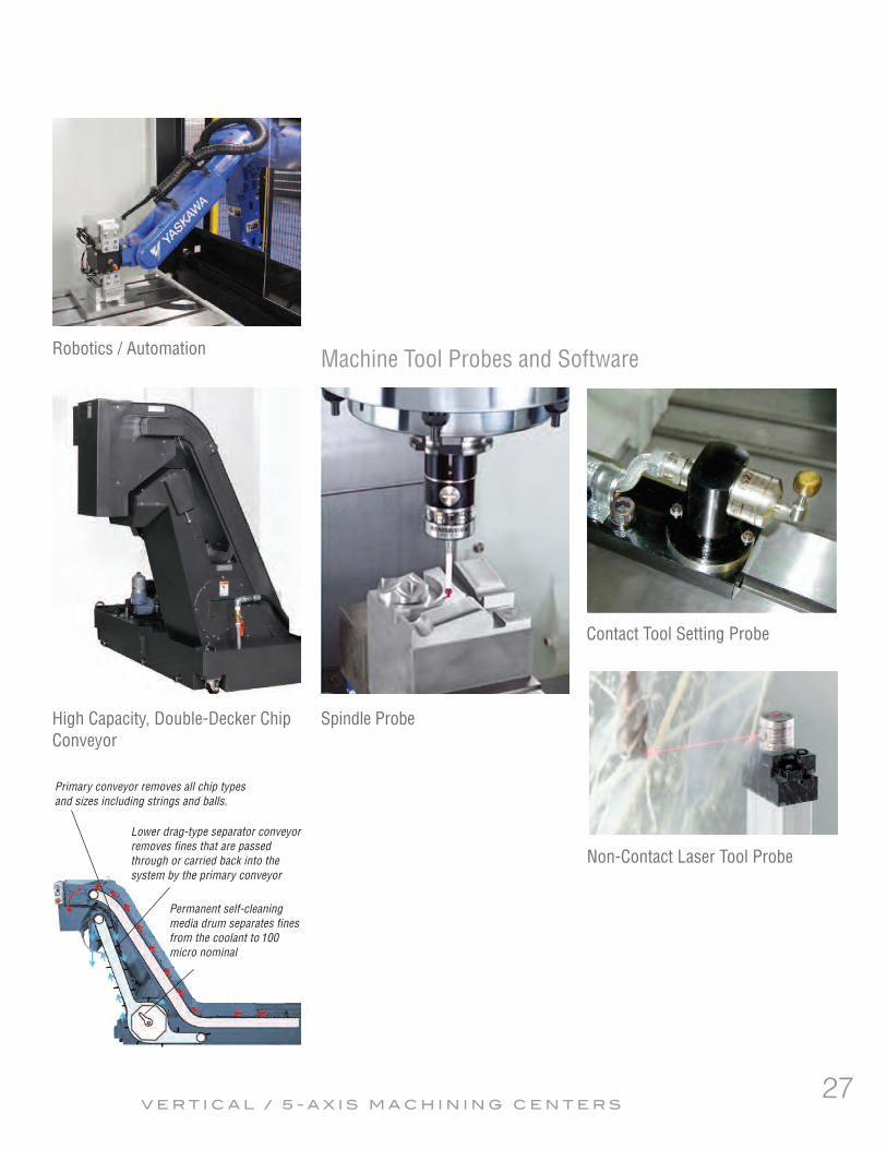
Spindle ProbeHigh Capacity, Double-Decker ChipConveyor
Contact Tool Setting Probe
Non-Contact Laser Tool Probe
Machine Tool Probes and SoftwareRobotics / Automation
Primary conveyor removes all chip typesand sizes including strings and balls.
Lower drag-type separator conveyorremoves fines that are passedthrough or carried back into thesystem by the primary conveyor
Permanent self-cleaningmedia drum separates finesfrom the coolant to 100micro nominal
27VERT ICAL / 5 - AX I S MACH IN ING CENTERS

430(16.9")
2882.4
(113.5
")
Y STROKE 455 (17.9")
215 - 670(8.5")-(26.4")
1362.4
(53.6"
)
460 (18.1"
)Z S
TROKE
110 (4.3")
570 (22.4"
)860 (33
.9")
90 (3.5")
682.4
(26.9"
)211
0(83
.1")
90 (3.5") 300
(11.8")1465(57.7")
330(13")
2095(82.5")
365 (14.4"
)840 (33
.1")
995 (39.2"
)
1100(43.3")
1100(43.3")
2200 (86.6")
900(35.4")X STROKE 760(29.9")
Mycenter-3XG/3XiG
Specifications subject to change without notice.
Mycent er - 3XG / 3 X i G
430 (16.9"
)SPINDLE CENTER
900 (35.4") 760 (29.9")X STROKE
205 (8.1")
455 (17.9"
)
215 (8.5") 130 (5.1
")
Y STRO
KE
880(34.6")
1100(43.3")
220(8.7")
10 (0.4")
455 (17.9"
)410 (16
.1")
153 (6")
187 (7.4")103 (4.1")
400 (15.7"
)
1345 (5
3")750 (29
.5")
2495 (9
8.2")
45(1.8")
225(8.9") 1660 (65.4")
225(8.9")
45(1.8")
140(5.5")
1100 (43.3") 1100 (43.3")
2200 (86.6")448.4(17.7")
2095(8
2.5")
2648.4 (104.3")Move-In DimensionsRequired Space W x D: 2,200 x 2,095mm (86.6" x 82.5")
Machine Height: 2,882mm (113.5")
Machine Net Weight: 5,520kg (12,144Lbs)
Power Requirement: 30KVA
.
.28

Mycenter-3XG/3XiG Sparkchanger
430 (16.9"
)
SPINDLE CENTER
455
(17.9"
) 21
5(8.5
")102
.7(4"
)
Y STRO
KE
POWER SUPPLY
1100 (43.3") 1100 (43.3")
10 (0.4")
455 (1
7.9")
1345(5
3")750
(29.5"
)
2567.6
(101.1
")2095 (8
2.5")
3601.4
(141.8
")
3735.3 (147.1")
Ø1286.4(Ø50.6")
1624 (63.9")
205
(8.1")
410
(16.1"
)
59.8
(2.4")
45.3(1.8")
242.7(9.6") 236
(9.3") 52(2")
1100 (43.3") 1100 (43.3")
2200 (86.6")
22.3(0.9")
760 (29.9")OPERATION
PANEL
864 (34")
280.2 (11
")
359.1(14.1")1176.2 (46.3")
670 (26.4")
138.9 (5.5
") 23
2.6 (9.2")
3051.9
(120.2
") 31
6.9(12
.5")
472.6 (18.6"
) 34
5.4(13
.6")
AIR
DOOR OPEN RANGE
979.6 (
38.6")
860 (33
.9")
360.4 (14.2"
)220
0 (86.6
")
3037.7
(119.6
")
624.9(24.6") 1345 (53")
750(29.5")
2719.9 (107.1")
495(19.5")
38(1.5")
837.7 (
33")
90 (3.5")
597.7
(23.5"
)
2238 (88.1")
1100(43.3")
1100(43.3")
800(31.5")
POWER SUPPLY
SHIPP
ING SIZ
E
DOOR OPEN RANGE
880 (34.6")
670(26.4")
2908 (114.5")
3065.3 (120.7")3065.3 (120.7") 345.4(13.6")
3065.3 (120.7")
SHIPPING SIZE
280.9(11.1")
506.2(19.9")
3414.2 (134.4")
SHIPPING SIZE
2350 (9
2.5")
2784.4 (109.6")
38(1.5")
2200 (86.6")
Specifications subject to change without notice.
Move-In DimensionsRequired Space W x D: 2,200 x 2,785mm (86.6" x 109.6")
Machine Height: 2,350mm (92.5")
Machine Net Weight: 7,320kg (16,104Lbs)
Power Requirement: 30KVA
Mycent er - 3Xg / 3X iG S p arkchanger
.
. 29

4046.5
(159.3
")
375.8
(14.8"
)
3338.9
(131.5
")
1162.9
(45.8"
)160
0(63")
576 (22
.7")
700 (27
.6")
928 (36
.5")
510
(20.1"
) 58
5(23
")
1095 (4
3.1")
135(5.3")
135(5.3")
656.5(25.8")765 (30.1")1800 (70.9")765 (30.1")
485.5(19.1")
4472 (176.1")104.7(4.1")
4576.7 (180.2")
40ATC MAGAZINE
1276 (5
0.2")
2062.9
(81.2"
)
AIR
COOL
ANT T
ANK
185
(7.3")
130.6
(5.1")
3469.5
(136.6
")
522.6
(20.6"
)
OPERATION PANEL
695 (27.4")
2350 (9
2.5")
1795 (70.7")
146.8
(5.8")
54.4
(2.1")
POWERSUPPLY
X STROKE 1530 (60.2")
1100 (4
3.3")
Move-In DimensionsRequired Space W x D: 2,506 x 4,472mm (98.7" x 176.1.")
Machine Height: 3,251mm (128.0")
Machine Net Weight: 17,500kg (38,500Lbs)
Power Requirement: 35/45KVA Specifications subject to change without notice.
Br i dgeCen t er - 6G # 40 & # 50 T a p er
Bridgecenter-6G 50 TAPER
Also available in #40 taper
1276 (50.2")2062.9 (81.2")
3338.9 (131.5")
4472 (176.1")104.7(4.1")
4576.7 (180.2")
710 (28
")152 (6"
)
862 (33
.9")
1280 (5
0.4")
1741(6
8.5")
2477 (9
7.5")
1406 (5
5.4")
47 (1.9")
862 (33
.9")
418
(16.5"
)
1800 (70.9")
Z STRO
KE
X STROKE 1530(60.2")
510 (20.1")585 (23")
1095(43.1")Y STROKE
1143 (45")
571.5(22.5")
571.5(22.5")
3883 (1
52.9")
130.6(5.1")
1800 (70.9")
1237.4 (48.7")
1012.3
(39.9"
)
3469.5 (136.6")
1100.9
(43.3"
) 69
1.5(27
.2")
924
(36.4"
)860
(33.9"
)
2506 (98.7")
3251 (1
28")
30

Br i dgeCen t er - 8G # 40 & # 50 T a p er
Specifications subject to change without notice.
Also available in #40 taper
Bridgecenter-8G 50 TAPER
1276 (50.2")2062.9 (81.2")
3338.9 (131.5")
5866 (230.9")
273.3(10.8")
6139.3 (241.7")
710 (28
")152 (6"
)
862
(33.9"
)128
0 (50.4
")174
1 (68.5
")
2477 (9
7.5")
1406 (5
5.4")
47 (1.9")
862 (33
.9")
418
(16.5"
)
2500 (98.4")
Z STR
OKE
X STROKE 2032 (80")
510 (20.1")585 (23")
1095 (43.1")Y STROKE
571.5(22.5")
571.5(22.5") 92
4(36
.4")
860(33
.9")
3883 (1
52.9")
130.6(5.1")
2365.3 (93.1")
1802.7 (71")
1012.3
(39.9"
)
3469.5 (136.6")
1100.9
(43.3"
) 69
1.5(27
.2")
1143 (45")
4046.5
(159.3
")
375.8
(14.8"
)
3338.9
(131.5
")
1162.9
(45.8"
)160
0 (63")
576 (22
.7")
700 (27
.6")
928 (36
.5")
510
(20.1"
) 58
5(23
")
1095 (4
3.1")
X STROKE 2032 (80") 234(9.2")
753 (29.6")1016 (40")2500 (98.4")1016 (40") 581
(22.9")
5866 (230.9") 273.3(10.8")
6139.3 (241.7")
40 ATC MAGAZINE
1276 (5
0.2")
2062.9
(81.2"
)
POWERSUPPLY
COOL
ANT T
ANK
185
(7.3")
130.6
(5.1")
3469.5
(136.6
")
522.6
(20.6"
)
OPERATION PANEL
695(27.4")
2350 (9
2.5")
1795 (70.7")
146.8
(5.8")
54.4
(2.1")
Move-In DimensionsRequired Space W x D: 2,571 x 5,866mm (101.2" x 230.9")
Machine Height: 3,251mm (128")
Machine Net Weight: 20,000kg (44,000Lbs)
Power Requirement: 45KVA
31

Br i dgeCen t er - 1 0G
Specifications subject to change without notice.
Bridgecenter-10G
1370 (5
3.9")
815 (32
.1")
800 (31
.5")
1615 (6
3.6")
2540 (100") 230(9.1")
230(9.1")
3000 (118.1") TABLE LENGTH1270 (50")
212.6
(8.4")
40ATC MAGAZINE
CONTROL BOX
X STROKE
797 (31.4")
565
(22.2"
)235
0 (92.5
")
1201.3(47.3")2802(110.3")
1253 (4
9.3")
4375.6
(172.3
")
3086.7(121.5")
Y STRO
KE
4168 (1
64.1")
1270 (50") 753 (29.6")
1740 (6
8.5")
2428 (9
5.6")
207.6 (8.2
")416
8 (164.
1")
663.1
455(17.9")
8208.1 (323.2")
POWERSUPPLY
AIR
455(17.9")
7545(297")
253
(10")
4633.6
(182.4
")
CHIP BUCKET (OPTION)
COOLANT TANK
CHIP CONVEYOR
250
(9.8")
7545 (297") (26.1")
3523 (138.7")3567 (140.4")
895(35.2")1200 (47.2")1808 (71.2")
7090 (279.1")
4421 (174.1") 7545 (297")
2270 (89.4")
455(17.9")
3187 (125.5")
3000 (118.1") 2540 (100")X-STROKETABLE LENGTH
Y-STROKE
800(31.5")
815(32.1")
1615 (63.6") 135(5.3")
1696 (66.8")
848 (33.4")848 (33.4")
230(9.1")2778 (109.4")1160 (45.7")
253(10")
1393.6
(54.9"
)261
2 (102.
8")
2820 (111")
DOOR OPEN RANGE
DOOR OPEN RANGE
150
(5.9")
800
(31.5"
)
897 (35
.3")
950 (37
.4")
2158.6
(85")
Z-STR
OKE
1015.9
(40")
47 (1.9")
674.6
(26.6"
)
4005.6
(157.7
")
CHIP BUCKET (OPTION)
ATC STROKE
Move-In DimensionsRequired Space W x D: 2,980 x 7,090mm (117.3" x 279.1º ")
Machine Height: 3,284mm (129.3")
Machine Net Weight: 27,000kg (59,400Lbs)
Power Requirement: 50KVA
32

Br i dgeCen t er - 1 2G
Specifications subject to change without notice.
Bridgecenter-12G
4093 (161.1")4187 (164.8")
1465 (57.7")1200 (47.2")1808 (71.2")
8280 (326")
4421 (174.1") 8735(343.9")
3090 (121.7")
455(17.9")
3807 (149.9")
3500 (137.8") 3050(120.1")X-STROKE
TABLE LENGTH
800(31.5")
815(32.1")
135(5.3")
ATC STROKE
1696 (66.8")
848 (33.4")848 (33.4")
230(9.1")2778 (109.4")1160 (45.7")
253(10")
1393.6
(54.9"
)261
2 (102.
8")
3640 (143.3")
DOOR OPEN RANGE
DOOR OPEN RANGE 150
(5.9")
800
(31.5"
)
897 (35
.3")
950 (37
.4")
2158.6
(85")
Z-STR
OKE
1015.9
(40")
47 (1.9")
674.6
(26.6"
)
4005.6
(157.7
")
CHIP BUCKET (OPTION)
Y-STROKE1615 (63.6")
1370 (5
3.9")
815 (32
.1")
800 (31
.5")
1615 (6
3.6")
3050 (120.1") 225(8.9")
225(8.9")
3500 (137.8") TABLE LENGTH1525 (60") 212.6
(8.4")
40 ATC MAGAZINE
CONTROL BOX
X STROKE
912 (35.9")
565
(22.2"
)235
0 (92.5
")
1771.3 (69.7")2802 (110.3")
1253 (4
9.3")
4375.6
(172.3
")
3706.7 (145.9")
8735 (343.9")
Y STR
OKE
4168 (1
64.1")
1525 (60") 818 (32.2")
1740 (6
8.5")
2428 (9
5.6")
207.6 (8.2
")416
8 (164.
1")
663.1(26.1")
455(17.9")
9398.1 (370")
POWERSUPPLY
AIR
455(17.9")
8735 (343.9")
253
(10")
4633.6
(182.4
")
CHIP BUCKET (OPTION)
COOLANT TANK
CHIP CONVEYOR
250
(9.8")
Move-In DimensionsRequired Space W x D: 2,980 x 8,280mm (117.3" x 326.0. ")
Machine Height: 3,284mm (129.3")
Machine Net Weight: 30,000kg (66,000Lbs)
Power Requirement: 50KVA
33

Mytrunnion-4G
975 (38.4")10.5(0.4")
707.3 (27.8")
305 (12") 305 (12")
X-AXIS STROKE 610(24")
305(12")
305(12")
Y-AXIS STROKE 610(24")
750
(29.5"
)650
(25.6"
)
Ø400(Ø15.7")
Z-AXIS
STRO
KE 50
0(19
.7")
150
(5.9") 10
0(3.9
")
50 (2"
)
462.7
(18.2"
)950
(37.4"
)878
.3 (34.
6")
2750 (108.3") 65(2.6")
1600(6
3") 35
0(13
.8")
60ATC MAGAZINE
1205 (47.4") 25.9 (1")
174.1 (6.9")
2421.3 (95.3")
30.8(1.2")
200 (7.
9")980
(38.6"
)770
(30.3"
) 34
1(13
.4")
3706.5 (145.9")
21.5 (0.8") 3620 (142.5") 65(2.6")
870(34.3")
2849.7
(112.2
")
558.7 (22")
2291 (9
0.2")
89 (3.5")
341
(13.4"
)195
0(76.8
")
0.49MPa
350 l/min(ANR)
CONTROL BOX
POWER SUPPLY
Ø400(Ø15.7")
948 (37.3")
MAINTENANCE AREA
MAINTENANCE AREA
2380 (9
3.7")
975 (38
.4")
520(20.5")
200 (7.
9")
662.4 (26.1")
395
(15.6"
)163
0 (64.2
") 35
5 (14")
365
(14.4"
)
105 (4.1")2295 (90.4")
1205 (4
7.4")
305
(12")
305
(12")
X-AXIS
STRO
KE 6
10 (24
")
305(12")
305(12")
Y-AXIS STROKE 610(24")
165
(6.5")
4655.3 (183.3")
597.3 (23.5")3706.5 (145.9") 351.5(13.8")
21.5(0.8") 3620 (142.5")
65(2.6")
3100 (122")
2421.3
(95.3"
)
30.8 (
1.2")
2380 (9
3.7")
10.5 (
0.4")
646 (25
.4")
1734 (6
8.3")
Move-In DimensionsRequired Space W x D: 2,216 x 3,707mm (87.2" x 145.9")
Machine Height: 2,337mm (92.0")
Machine Net Weight: 9,100kg (20,020Lbs)
Power Requirement: 45KVA
Mytrunn i on - 4GSpecifications subject to change without notice.34

4169 (1
64.1")
2600 (1
02.4")
1569 (6
1.8")
1500 (59.1")2172 (85.5") 21.5(0.8")3672 (144.6")
30.8(1.2")
595(23.4")
595(23.4")
1190 (46.9") 250(9.8")
400(15.7")
3724.3 (146.6")
1110
(43.7"
)915
(36")
765
(30.1"
) 15
0(5.9
")
815
(32.1"
) 10
0(3.9
")
1335 (52.6")
600(23.6")
735(28.9")
Z-STR
OKE
1110 (4
3.7")
740
(29.1"
)
Y-STROKE
2600 (1
02.4")
1569 (6
1.8")
175
(6.9")
Ø1170(Ø46.1")
5255 (206.9") 65
(2.6")5320 (209.4")
121
(4.8")
X-STROKE
1570 (61.8")
562.3(22.1")
1260 (49.6") 69
5.2(27
.4")
897.5
(35.3"
) 67
1.5(26
.4")
30°
120° R705(R27.8")
1015.3
(40")
672(26.5")
3922.5
(154.4
")
3000 (118.1")
3396 (1
33.7")
595 (23
.4")
595 (23
.4")
1190 (4
6.9")
250
(9.8")
735 (28.9") 600 (23.6")
1335 (52.6")Y-STROKE
X-STR
OKE
ATC ST
ROKE
Ø1170(Ø46.1")
Ø1000(Ø39.4")
1830 (72") 3425 (134.8")
5255 (206.9") 517.6(20.4")
1500 (5
9.1")
2172 (8
5.5")
400
(15.7"
)367
2 (144.
6") 37
6.5(14
.8")
4448.5
(175.1
")
POWER SUPPLY
AIR
1100 (43.3")
582.4 (22.9")5772.6 (227.3")
6355 (250.2")
787.1 (31")
Ø600
(Ø23.6")
Ø250(Ø9.8")
CONT
ROL B
OXCOOLANT TANK
OPERATION PANEL
MAINTENANCE AREAMAGAZINE SIDE STEP
SPINDLE CENTER
60 ATC MAGAZINE
295.4
(11.6"
)
Specifications subject to change without notice.
Mytrunnion-7G
Mytrunn i on - 7G
Move-In DimensionsRequired Space W x D: 3,000 x 5,320 (118.1" x 209.4")
Machine Height: 3,396mm (133.7")
Machine Net Weight: 33,000kg (72,600Lbs)
Power Requirement: 65KVA
35

Kitamura Machinery Co., Ltd. (Headquarters)1870-Toide, Takaoka-City, Toyama Pref., JapanTEL: (0766) 63-1100 FAX: (0766) 63-1128www.kitamura-machinery.co.jp E-mail: [email protected]
PRINTED IN USA 04 /16 3M
Kitamura Machinery GmbH (Düsseldorf)Wahlerstrasse 39, 40472 Düsseldorf, GermanyTEL: (0211) 65-6077 FAX: (0211) 904-7916www.kitamura-machinery.eu Email: [email protected]
Kitamura Machinery of U.S.A., Inc. (Chicago)78 East Century Drive, Wheeling, Illinois 60090 U.S.A. TEL: (847) 520-7755 FAX: (847) 520-7763www.kitamura-machinery.com E-mail: [email protected]
Kitamura GmbHDüsseldorf, Germany
US CORPORATEHEADQUARTERSWheeling, IL
HEADQUARTERSTakaoka City,Toyama Pref.,
Japan