Embed Size (px)
Citation preview

MX6 Reference Guide (For Microsoft® Windows Mobile® Equipped MX6’s)
IMPORTANT NOTICE - The LXE MX6 computers and accessories are obsolete. This
electronic manual has been made available as a courtesy to LXE’s MX6 customers. Please contact your LXE customer support representative for replacement and assistance.
Copyright © March 2006 by LXE Inc. All Rights Reserved E-EQ-MX6RG-E-ARC

Notices LXE Inc. reserves the right to make improvements or changes in the products described in this document at any time without notice. While reasonable efforts have been made in the preparation of this document to assure its accuracy, LXE assumes no liability resulting from any errors or omissions in this document, or from the use of the information contained herein. Further, LXE Incorporated, reserves the right to revise this document and to make changes to it from time to time without any obligation to notify any person or organization of such revision or changes. Copyright: This document is copyrighted. All rights are reserved. This document may not, in whole or in part, be copied, photocopied, reproduced, translated or reduced to any electronic medium or machine-readable form without prior consent, in writing, from LXE Inc. Copyright © 2006 by LXE Inc. An EMS Technologies Company. 125 Technology Parkway, Norcross, GA 30092 U.S.A. (770) 447-4224 Trademarks: LXE® is a registered trademark of LXE Inc. Microsoft, ActiveSync, MSN, Outlook, Windows, all Microsoft Windows logos, and Windows Media are either registered trademarks or trademarks of Microsoft Corporation in the United States and/or other countries. Sun, Sun Microsystems, Java, all trademarks and logos that contain Sun or Java, are trademarks or registered trademarks of Sun Microsystems, Inc. in the United States and other countries. RAM® and RAM Mount™ are both trademarks of National Products Inc., 1205 S. Orr Street, Seattle, WA 98108. When this manual is in PDF format: "Acrobat ® Reader Copyright © 1987-2006 Adobe Systems Incorporated. All rights reserved. Adobe, the Adobe logo, Acrobat, and the Acrobat logo are trademarks of Adobe Systems Incorporated." applies. All other brand or product names are trademarks or registered trademarks of their respective companies or organizations. Note: The original equipment’s User Manuals are copyrighted by Hand Held Products® Incorporated. This
manual has been amended by LXE® Inc., for the MX6 and MX6 Docking Cradles with Hand Held Product’s express permission.
Important: This symbol is placed on the product to remind users to dispose of Waste Electrical and Electronic Equipment (WEEE) appropriately, per Directive 2002-96-EC. In most areas, this product can be recycled, reclaimed and re-used when properly discarded. Do not discard labeled units with trash. For information about proper disposal, contact LXE through your local sales representative, or visit www lxe com.
Initial Release Dec 2003, Rev B Aug 2004, Rev C Feb 2005, Rev D October 2005, Rev E March 2006 Archived December 2008

Revision Notice
Notices Changed HHP® to Hand Held Products® where applicable. Added register mark to RAM® mounting products.
Chapter 1 – Introduction
Accessories: Added MX6A420CASELASERNH and MX6A421CASELASERNH (for MX6 with laser scanner and without a handle).
Chapter 3 – Physical Description and Layout
Added “LXE recommends all MX6 battery packs be Analyzed on a monthly basis. Analyzing will reset the internal battery charge indicator circuit, the gas gauge, as well as analyze the battery.” to the “Multicharger” section.
Chapter 4 – System Configuration
Rearranged sections to reflect changes between Windows Mobile OS versions 7.03, 7.11 and 7.13: Meetinghouse AEGIS Client Settings | System Tab | Scanner – Version 7.03 Settings | System Tab | Scanner – Version 7.11 and 7.13 Settings | System Tab | Screen – Version 7.03 Settings | System Tab | Screen – Version 7.11 and 7.13 Settings | Connections Tab – Version 7.03 Settings | Connections Tab – Versions 7.11 and 7.13. Added “Control Characters Tab” to “Scanner”. Added “JAVA (Option)” section. Added “Power Tools (Version 7.13)”, “MX6 Utilities” and “Power Tools EZConfig Utilities” sections. Expanded instruction for “Ping”, “RASMan” and “Route”.
Chapter 5 – AppLock Added “Multi Application Configuration” instruction.
Appendix B –Technical Specifications
Moved section titled Revision History from Chapter 1 – Introduction to end of Technical Specifications appendix. Added sections “Scanner Specifications”, “COM Port Specifications”, and “Symbologies”.
Appendix C – MX6 Multicharger
Added “LXE recommends all MX6 battery packs be Analyzed on a monthly basis. Analyzing will reset the internal battery charge indicator circuit, the gas gauge, as well as analyze the battery.” to the “Introduction” section.
Entire Manual Updated path statements and instructions based on Version 7.03 vs 7.11 vs 7.13. Updated graphics to display LXE 2005 logo..


E-EQ-MX6RG-E-ARC MX6 Reference Guide
Table of Contents
CHAPTER 1 INTRODUCTION 1
Overview ................................................................................................................................. 1 Identify Your MX6 Device ......................................................................................................2 Important Battery Information...............................................................................................2 Components ........................................................................................................................... 3 When to Use This Guide........................................................................................................6
Document Conventions....................................................................................................................... 7 Using the Stylus ..................................................................................................................... 8 System Tray Icons.................................................................................................................. 9 General Windows Keyboard Shortcuts................................................................................9 Soft Input Panel .................................................................................................................... 10
Repeating Keystrokes ....................................................................................................................... 10 International Characters .................................................................................................................. 10
Getting Help.......................................................................................................................... 11 User Guides........................................................................................................................................ 11 Accessories ......................................................................................................................................... 11
CHAPTER 2 GETTING STARTED 13
First . . . ................................................................................................................................. 13 In Brief ................................................................................................................................... 13 Insert Fully Charged Battery ...............................................................................................14
Low Battery Condition ..................................................................................................................... 14 Power Key............................................................................................................................. 15 Connect External Power Supply .........................................................................................15 Align the Touchscreen.........................................................................................................16 Set the Date and Time..........................................................................................................17 Setting Display Backlight Action ........................................................................................18
Dim Backlight if device is not used for:........................................................................................... 19 Turn off backlight if device is not used for:.................................................................................... 19 Turn on backlight when a button is pressed or the screen is tapped ........................................... 19 Backlight Intensity ............................................................................................................................ 19
Set the Power Off Timer.......................................................................................................20 On battery power .............................................................................................................................. 20 On external power............................................................................................................................. 20
Accessing Files in Flash Memory.......................................................................................21 My Documents Folder....................................................................................................................... 21 The IPSM Folder............................................................................................................................... 21
Saving Your Changes ..........................................................................................................21 Connect the Headset (Optional)..........................................................................................22 Set The Audio Speaker Volume ..........................................................................................23 Adjust the Handstrap...........................................................................................................24 Enter Data ............................................................................................................................. 25
Keypad Entry .................................................................................................................................... 25

6 Table of Contents
MX6 Reference Guide E-EQ-MX6RG-E-ARC
Stylus Data Entry .............................................................................................................................. 25 Using the Integrated Imager or Barcode Scanner ......................................................................... 26
Preparation........................................................................................................................................ 26 Edit Scanner/Imager Decoding Parameters (optional)................................................................... 26 Scanner Setup ................................................................................................................................ 26
Using the Imager / Barcode Scanner ................................................................................................ 26 Distance from Label....................................................................................................................... 27 Successful Scan.............................................................................................................................. 27 Unsuccessful Scan ......................................................................................................................... 27
Scan Ranges...................................................................................................................................... 27 Aiming at a Barcode......................................................................................................................... 28
Tethered Scanners............................................................................................................... 29 ActiveSync – Initial Setup....................................................................................................30
Install ActiveSync on Desktop/Laptop ............................................................................................ 30 Troubleshooting................................................................................................................................ 30
Serial Connection .............................................................................................................................. 30 USB Connection ................................................................................................................................ 31 IrDA Connection ............................................................................................................................... 31 Radio .................................................................................................................................................. 31 Connect .............................................................................................................................................. 31
CHAPTER 3 PHYSICAL DESCRIPTION AND LAYOUT 33
Hardware Configuration ......................................................................................................33 System Hardware.............................................................................................................................. 33 Central Processing Unit.................................................................................................................... 33 Core Logic.......................................................................................................................................... 34 System Memory................................................................................................................................. 34 Video Subsystem ............................................................................................................................... 34 Power Supply..................................................................................................................................... 34 Audio Interface.................................................................................................................................. 34 Secure Digital Cards ......................................................................................................................... 35
SD Installation / Removal ................................................................................................................ 35 COM Ports............................................................................................................................. 36
RS-232 Serial Port............................................................................................................................. 37 Integrated Imager or Scanner.......................................................................................................... 38
The Imager........................................................................................................................................ 38 The Scanner ...................................................................................................................................... 39
Tethered Scanners............................................................................................................................. 39 IR Port................................................................................................................................................ 39
Reset or Reboot.................................................................................................................... 40 Soft Reset ........................................................................................................................................... 40 Hard Reset ......................................................................................................................................... 40 Troubleshooting – Cold Boot/Hard Reset....................................................................................... 40 Upgrading the Mobile Device OS .................................................................................................... 41
Power Modes ........................................................................................................................ 42 On Mode............................................................................................................................................. 42
The Display ...................................................................................................................................... 42 The MX6 .......................................................................................................................................... 42
New Unit........................................................................................................................................ 42 Both Batteries Dead ....................................................................................................................... 43

Table of Contents 7
E-EQ-MX6RG-E-ARC MX6 Reference Guide
Main Battery Hot-swapped ............................................................................................................ 43 Suspend Mode ................................................................................................................................... 43 Off Mode ............................................................................................................................................ 43
The Keypads......................................................................................................................... 44 Special Keys ....................................................................................................................................... 45 Modifier Keys CTRL and ALT ....................................................................................................... 46 Keypress Sequences .......................................................................................................................... 46 Function Keys.................................................................................................................................... 46
Touch Screen........................................................................................................................ 47 Display Backlight Timer................................................................................................................... 47 Cleaning the Glass Display and Imager Aperture ......................................................................... 47
Speaker ................................................................................................................................. 48 Battery................................................................................................................................... 49
Checking Battery Status ................................................................................................................... 49 Handling Batteries Safely ....................................................................................................50
Main Battery Pack ............................................................................................................................ 50 Battery Hot-Swapping ...................................................................................................................... 50 Low Battery Warning ....................................................................................................................... 51 Backup Battery.................................................................................................................................. 51 Battery Maintenance Publication .................................................................................................... 51
Charging the Main Battery Pack .........................................................................................52 Using the Four Bay Charger/Analyzer (Optional)......................................................................... 52 Charging a Battery Using the Desktop Docking Cradle................................................................ 53
Docking Cradles................................................................................................................... 53 Indicators and LEDs......................................................................................................................... 54
Powered Desktop Cradle .................................................................................................................. 54 Powered Vehicle Cradle ................................................................................................................... 54
CHAPTER 4 SYSTEM CONFIGURATION 55
Introduction .......................................................................................................................... 55 Windows for Pocket PC.......................................................................................................55 Installed Software................................................................................................................. 55
View System Information ................................................................................................................. 55 Installed Software................................................................................................................. 56
Software Load ................................................................................................................................... 56 JAVA (Optional) .............................................................................................................................. 56 LXE RFTerm (Optional) .................................................................................................................. 56 AppLock (Optional) ......................................................................................................................... 57 WaveLink Avalanche (Optional)...................................................................................................... 57
Power Tools (Version 7.13 only) .........................................................................................57 Power Tools Panel ............................................................................................................................. 58
The Start Menu ..................................................................................................................... 59 Edit Start Menu Item List ................................................................................................................ 60
Programs .............................................................................................................................. 61 Installed Programs............................................................................................................................ 61 ActiveSync.......................................................................................................................................... 62
Synchronizing from the MX6........................................................................................................... 63 Avalanche (Optional) ........................................................................................................................ 63
WaveLink Avalanche Enabler.......................................................................................................... 63 Calculator .......................................................................................................................................... 64

8 Table of Contents
MX6 Reference Guide E-EQ-MX6RG-E-ARC
Calendar............................................................................................................................................. 64 Demo Programs................................................................................................................................. 64 File Explorer...................................................................................................................................... 64 Find..................................................................................................................................................... 64 Games................................................................................................................................................. 65 Help .................................................................................................................................................... 65 Inbox (Version 7.03 only) ................................................................................................................. 65 Internet Explorer .............................................................................................................................. 65 LXE RFTerm (Optional) .................................................................................................................. 65 Meetinghouse AEGIS Client ............................................................................................................ 66
AEGIS Client Icon Indicator ............................................................................................................ 66 Getting Started.................................................................................................................................. 67
When Using LEAP ........................................................................................................................ 67 When Using WEP.......................................................................................................................... 67
Ver 7.03....................................................................................................................................... 67 Ver 7.11 and Ver 7.13 ................................................................................................................. 67
When Using WPA.......................................................................................................................... 67 Main Screen...................................................................................................................................... 68 The Configure Menu Option ............................................................................................................ 70
User tab .......................................................................................................................................... 70 System tab...................................................................................................................................... 71 Server tab ....................................................................................................................................... 72
Wireless Networks Tab .................................................................................................................... 73 Protocol Tab ..................................................................................................................................... 75
Profile Info tab ............................................................................................................................... 76 WEP Mgmt tab .............................................................................................................................. 77 WPA Settings tab........................................................................................................................... 79
Meetinghouse Certificate Installer .................................................................................................. 80 Certificate Requirements .................................................................................................................. 80 Installing Certificates with CertAdd................................................................................................. 80
MSN Messenger................................................................................................................................. 81 Notes ................................................................................................................................................... 81 Pictures............................................................................................................................................... 81 Pocket Excel....................................................................................................................................... 81 Pocket MSN ....................................................................................................................................... 81 Pocket Word ...................................................................................................................................... 82 Tasks................................................................................................................................................... 82 Utils..................................................................................................................................................... 82
MX6 Utilities.......................................................................................................................... 83 BattMon ............................................................................................................................................. 83 EZConfig Utilities.............................................................................................................................. 84 Hotkeys............................................................................................................................................... 85 IPConfig ............................................................................................................................................. 85 Keyboard Status ................................................................................................................................ 86 Network Utilities ............................................................................................................................... 86 NoSIP.................................................................................................................................................. 86 Ping..................................................................................................................................................... 87
Using the Ping Input Tab Parameters ............................................................................................... 87 Reading the Ping Output Tab Display.............................................................................................. 88
RASMan............................................................................................................................................. 89 To Enable RASMan ......................................................................................................................... 89

Table of Contents 9
E-EQ-MX6RG-E-ARC MX6 Reference Guide
To Disable RASMan ........................................................................................................................ 89 RASMan Command Bar Menu ........................................................................................................ 89 RASMan Configuration File ............................................................................................................ 90
Reboot ................................................................................................................................................ 91 RegBackup......................................................................................................................................... 92 RegEdit............................................................................................................................................... 92 RegRestore......................................................................................................................................... 93 Route .................................................................................................................................................. 93
Command Drop Down List .............................................................................................................. 93 Suspend .............................................................................................................................................. 94 SysInfo................................................................................................................................................ 94
Settings Options................................................................................................................... 95 Personal Tab...................................................................................................................................... 95
Buttons.............................................................................................................................................. 96 Up/Down Control .......................................................................................................................... 96
Headset ............................................................................................................................................. 97 Input.................................................................................................................................................. 98 Menus ............................................................................................................................................... 98 Owner Information ........................................................................................................................... 99 Password......................................................................................................................................... 100 Sounds and Notifications................................................................................................................ 101 Today.............................................................................................................................................. 101
System Tab....................................................................................................................................... 102 About .............................................................................................................................................. 102 Backlight ........................................................................................................................................ 103 Certificates...................................................................................................................................... 104 Clear Type Tuner............................................................................................................................ 104 Clock and Alarms ........................................................................................................................... 105 CPU Speed...................................................................................................................................... 105 Memory .......................................................................................................................................... 106
Running Programs ....................................................................................................................... 106 Power.............................................................................................................................................. 107 Regional Settings............................................................................................................................ 108 Remove Programs .......................................................................................................................... 108 Scanner ........................................................................................................................................... 109
Version 7.03................................................................................................................................. 109 Version 7.11 and 7.13 .................................................................................................................. 110
Advanced Tab ........................................................................................................................... 111 Translate Control Codes ......................................................................................................... 111 Strip Leading / Strip Trailing Characters................................................................................ 112 Prefix / Suffix ......................................................................................................................... 112
Control Characters Tab ............................................................................................................. 113 Assigned Replacements for Block and Key Message Modes................................................. 114 Interaction between Strip Leading/Trailing and Prefix/Suffix Settings ................................. 115
COM1 Tab................................................................................................................................. 116 Screen ............................................................................................................................................. 117
Version 7.03................................................................................................................................. 117 Version 7.11 and 7.13 .................................................................................................................. 118
Alignment.................................................................................................................................. 118 ClearType .................................................................................................................................. 119 Text Size.................................................................................................................................... 119

10 Table of Contents
MX6 Reference Guide E-EQ-MX6RG-E-ARC
Connections Tab – Version 7.03 .................................................................................................... 120 Beam............................................................................................................................................... 121 Connections .................................................................................................................................... 122
Tasks tab ...................................................................................................................................... 122 Advanced tab ............................................................................................................................... 123 Configure a Network Adapter...................................................................................................... 124
Pegasus Settings ............................................................................................................................. 125 Status Tab .................................................................................................................................... 125 Ping Utility................................................................................................................................... 126 Config Tab ................................................................................................................................... 127
Operation Buttons ..................................................................................................................... 127 Preferred Profiles....................................................................................................................... 128 Active SSIDs ............................................................................................................................. 128
Advanced Tab .............................................................................................................................. 129 Power Save Mode...................................................................................................................... 129 802.11b Preamble Mode ........................................................................................................... 129
About ........................................................................................................................................... 130 Radio Manager ............................................................................................................................... 131 Creating and Modifying Profiles .................................................................................................... 132
When Using LEAP ...................................................................................................................... 132 When Using WEP........................................................................................................................ 133 When Using WPA........................................................................................................................ 133 Create a New Profile.................................................................................................................... 133
Advanced................................................................................................................................... 134 Modify an Existing Profile........................................................................................................... 134
Network Name and Type .......................................................................................................... 135 WEP Parameters........................................................................................................................ 135
Deleting a Profile ......................................................................................................................... 136 Network Adapters........................................................................................................................... 137
Connections Tab – Version 7.11 and 7.13 ..................................................................................... 139 802.11b ........................................................................................................................................... 140
Status Tab .................................................................................................................................... 140 Ping Utility................................................................................................................................... 141 Config Tab ................................................................................................................................... 142
Operation Buttons ..................................................................................................................... 142 Preferred Profiles....................................................................................................................... 143 Active SSIDs ............................................................................................................................. 143 Network Name and Type .......................................................................................................... 144
Network Profile ...................................................................................................................... 145 Authentication ........................................................................................................................ 145 Encryption .............................................................................................................................. 146
Advanced Tab .............................................................................................................................. 147 Power Save Mode...................................................................................................................... 147 802.11b Preamble Mode ........................................................................................................... 147
About ........................................................................................................................................... 148 Beam............................................................................................................................................... 149 Connections .................................................................................................................................... 150
Tasks tab ...................................................................................................................................... 150 Advanced tab ............................................................................................................................... 151
Network Cards................................................................................................................................ 152 Wireless tab.................................................................................................................................. 152

Table of Contents 11
E-EQ-MX6RG-E-ARC MX6 Reference Guide
Network Adapters tab .................................................................................................................. 153 Configure a Network Adapter ........................................................................................................ 154 Radio Manager ............................................................................................................................... 155 Creating and Modifying Profiles .................................................................................................... 156
When Using LEAP ...................................................................................................................... 156 When Using WEP........................................................................................................................ 156 When Using WPA........................................................................................................................ 156 Create a New Profile.................................................................................................................... 157 Modify an Existing Profile........................................................................................................... 158
Network Profile tab ................................................................................................................... 158 Authentication Properties tab .................................................................................................... 159 Encryption tab ........................................................................................................................... 159
Deleting a Profile ......................................................................................................................... 160 Power Tools EZConfig Utilities .........................................................................................161
Using the EZConfig Client ............................................................................................................. 162 Using the EZConfig Editor............................................................................................................. 163
Configuration Files......................................................................................................................... 163 Locked and Encrypted Sections and Keys ..................................................................................... 164 Administrator Mode (Optional)...................................................................................................... 164 Launching Associated Applications ............................................................................................... 165 File Menu ....................................................................................................................................... 166 Edit Menu ....................................................................................................................................... 167
Editing Sections ........................................................................................................................... 167 Commands................................................................................................................................. 167 Modifying Section Names and Descriptions............................................................................. 168 Moving Sections........................................................................................................................ 168
Editing Keys ................................................................................................................................ 169 Commands................................................................................................................................. 169 Modifying Key Values and Descriptions .................................................................................. 169 Moving Keys ............................................................................................................................. 170
Tools Menu..................................................................................................................................... 170 Editing and Moving Sections ......................................................................................................... 171 Editing and Moving Keys............................................................................................................... 171 Associating Applications................................................................................................................ 171
Command Line Options............................................................................................................... 172 Autorun ............................................................................................................................................ 173
Autorun........................................................................................................................................... 173 Autorun Configuration File.......................................................................................................... 173
Settings Section ......................................................................................................................... 173 Programs Section....................................................................................................................... 174
Editing the Autorun Configuration File ....................................................................................... 175 Adding a Program Section ........................................................................................................... 175 Startup Options (StartupOption key) ........................................................................................... 176 Applying Startup Options to the Autorun Configuration File ..................................................... 176
AutoInstall ...................................................................................................................................... 177 Program Install Locations ............................................................................................................ 177
DemosMenu ..................................................................................................................................... 178 Settings Section .............................................................................................................................. 178 Menu Entries Section ..................................................................................................................... 179
Child Section Keys ...................................................................................................................... 180 The Exit Section ............................................................................................................................. 181

12 Table of Contents
MX6 Reference Guide E-EQ-MX6RG-E-ARC
Set EZConfig Utilities Menu to Silent Mode ................................................................................. 181 DeviceConfig.................................................................................................................................... 182
Enabling the File............................................................................................................................. 182 Autorun and DeviceConfig............................................................................................................. 182 System Panel Applets and DeviceConfig ....................................................................................... 182 DeviceConfig Sections and Keys ................................................................................................... 183
Connections Section..................................................................................................................... 183 Beam Section............................................................................................................................. 183 Radio Manager Section ............................................................................................................. 183
802.11b Section ...................................................................................................................... 183 WEP Section 185
Bluetooth Section ................................................................................................................... 185 Bluetooth Default Printer Values 186
GSM Section........................................................................................................................... 187 ActiveSync Section ................................................................................................................... 187
System Section............................................................................................................................. 188 Welcome Screen Section........................................................................................................... 188
Launching DeviceConfig.exe ................................................................................................. 188 Autorun.ini.............................................................................................................................. 188
Applications Section .................................................................................................................... 188 MSM Section............................................................................................................................. 188 Internet Explorer Section .......................................................................................................... 189
Command Line Arguments ............................................................................................................ 189 Launching DeviceConfig.exe Manually......................................................................................... 189
EZConfig Menu............................................................................................................................... 190 Settings ........................................................................................................................................... 190 Set EZConfig Utilities Menu to Silent Mode ................................................................................. 191
ImageDemo ...................................................................................................................................... 191 Settings ........................................................................................................................................... 191
Network Menu................................................................................................................................. 193 Settings ........................................................................................................................................... 193 Menu Entries Section ..................................................................................................................... 194
Child Section Keys ...................................................................................................................... 194 The Return Section ......................................................................................................................... 195 Set EZConfig Utilities Menu to Silent Mode ................................................................................. 195
Power Tools Menu........................................................................................................................... 196 Settings ........................................................................................................................................... 196 Menu Entries Section ..................................................................................................................... 198
Child Section Keys ...................................................................................................................... 198 The Exit Section ............................................................................................................................. 199 Set EZConfig Utilities Menu to Silent Mode ................................................................................. 199
PrintDemo Menu............................................................................................................................. 200 Settings ........................................................................................................................................... 200
Child Section Keys ...................................................................................................................... 201 The Return Section ......................................................................................................................... 201 Set EZConfig Utilities Menu to Silent Mode ................................................................................. 201
RASMan........................................................................................................................................... 202 Settings ........................................................................................................................................... 202
RFSettings........................................................................................................................................ 203 Settings ........................................................................................................................................... 203
Scandemo ......................................................................................................................................... 204

Table of Contents 13
E-EQ-MX6RG-E-ARC MX6 Reference Guide
Settings ........................................................................................................................................... 204 Decode ......................................................................................................................................... 204 Symbologies................................................................................................................................. 208 Centering...................................................................................................................................... 211
SetDevice Info.................................................................................................................................. 212 Hat Encoding ...................................................................................................................... 213 Decimal - Hexadecimal Chart ............................................................................................215
CHAPTER 5 APPLOCK 217
Introduction ........................................................................................................................ 217 Setup a New Device ...........................................................................................................217
Multi-Application Version.............................................................................................................. 218 Single Application Version ............................................................................................................. 218
Administration Mode..........................................................................................................219 End User Mode ................................................................................................................... 219 Passwords .......................................................................................................................... 220 Multi-Application Configuration........................................................................................221
Application Panel ............................................................................................................................ 221 End User Internet Explorer (EUIE) ................................................................................................ 222
Security Panel .................................................................................................................................. 223 Password......................................................................................................................................... 224
Status Panel ..................................................................................................................................... 225 End-User Switching Technique ..................................................................................................... 227
Using a Stylus Tap.......................................................................................................................... 227 Using a Hotkey Sequence............................................................................................................... 227
Troubleshooting Multi-Application AppLock.............................................................................. 228 Single Application Configuration .....................................................................................229
Control Panel................................................................................................................................... 229 Security Panel .................................................................................................................................. 230 Status Panel ..................................................................................................................................... 231
AppLock Error Messages..................................................................................................233 AppLock Registry Settings ...............................................................................................240
CHAPTER 6 SCANNER/IMAGER PARAMETER SETUP 241
Introduction ........................................................................................................................ 241 Identification....................................................................................................................... 241 Decoder............................................................................................................................... 242
DecodeMode – Imager Only........................................................................................................... 242 LinearRange – Imager Only .......................................................................................................... 242 LeaveLightsOn – Imager Only ...................................................................................................... 242 AimTime .......................................................................................................................................... 243
Centering – Imager Only....................................................................................................243 Symbologies....................................................................................................................... 244
Imager/Scanner/Symbology Quick Reference.............................................................................. 244 Aztec – Imager Only ....................................................................................................................... 244 Mesa – Imager Only........................................................................................................................ 245 Codabar............................................................................................................................................ 245 Codablock – Imager Only .............................................................................................................. 245

14 Table of Contents
MX6 Reference Guide E-EQ-MX6RG-E-ARC
Code 11............................................................................................................................................. 245 Code 128........................................................................................................................................... 246 Code 39............................................................................................................................................. 246 Code 49 – Imager Only ................................................................................................................... 246 Code 93............................................................................................................................................. 246 EAN-UCC Composite – Imager Only ........................................................................................... 247 Data Matrix – Imager Only............................................................................................................ 247 EAN 8 ............................................................................................................................................... 247 EAN 13 ............................................................................................................................................. 247 IATA2 5............................................................................................................................................ 248 Interleaved 2 of 5............................................................................................................................. 248 Maxicode – Imager Only ................................................................................................................ 248 MicroPDF417 – Imager Only......................................................................................................... 248 MSI ................................................................................................................................................... 249 OCR – Imager Only ........................................................................................................................ 249
Examples: ....................................................................................................................................... 250 PDF417 – Imager Only ................................................................................................................... 250 Planet – Imager Only ...................................................................................................................... 251 Postnet – Imager Only .................................................................................................................... 251 QR Code – Imager Only ................................................................................................................. 251 RSS Code ......................................................................................................................................... 251 UPCA................................................................................................................................................ 252 UPCE0.............................................................................................................................................. 252 UPCE1.............................................................................................................................................. 252 ISBT.................................................................................................................................................. 253 BPO – Imager only.......................................................................................................................... 253 Canpost – Imager only.................................................................................................................... 253 Auspost – Imager only .................................................................................................................... 253 JapanPost – Imager only ................................................................................................................ 253 DutchPost – Imager only ................................................................................................................ 253 TLC – Imager only.......................................................................................................................... 254
Sample SCANCONFIG.INI File...........................................................................................254
CHAPTER 7 WIRELESS NETWORK CONFIGURATION 257
Introduction ........................................................................................................................ 257 Configuring an MX6 Radio without WPA .........................................................................257 Configuring an MX6 Radio for WPA .................................................................................257
In Brief . . . ....................................................................................................................................... 258 Prerequisites ................................................................................................................................... 258
Verify Date and Time on the MX6 .............................................................................................. 259 Install Certificates on the MX6.................................................................................................... 260
About CertAdd .......................................................................................................................... 260 Installing Certificates with CertAdd.......................................................................................... 260
Authentication Configuration PEAP/MS-CHAP......................................................................... 262 Set up User Authentication Profile................................................................................................. 262 Skip Server Validation ................................................................................................................... 264 Setup Radio Profile to Connect to Network ................................................................................... 265 Configure Radio Profile WPA Settings.......................................................................................... 267 Add Server Authentication/Validation to User Profile................................................................... 267
Authentication Configuration PEAP/GTC................................................................................... 270
Table of Contents 15
E-EQ-MX6RG-E-ARC MX6 Reference Guide
Set up User Authentication Profile................................................................................................. 270 Skip Server Validation Step ........................................................................................................... 273 Setup Radio Profile to Connect to Network ................................................................................... 274 Configure Radio Profile WPA Settings.......................................................................................... 276 Add Server Authentication /Validation to User Profile.................................................................. 277
Authentication Configuration EAP-TLS ..................................................................................... 279 Set Up User Authentication Profile ................................................................................................ 279 Skip Server Validation Step ........................................................................................................... 281 Setup Radio Profile to Connect to Network ................................................................................... 282 Configure Radio Profile WPA Settings.......................................................................................... 284 Add Server Authentication /Validation to User Profile.................................................................. 285
WPA-PSK Radio Configuration.................................................................................................... 287 Setup Radio Profile to Connect to Network ................................................................................... 287 Configure Radio Profile WPA Settings.......................................................................................... 289
APPENDIX A KEY MAPS 291
35-Key Numeric-Alpha Keypad.........................................................................................291 Inactive Keys on the 35-key Keypad ............................................................................................. 295
56-Key Full Alpha Numeric Keypad..................................................................................296
APPENDIX B TECHNICAL SPECIFICATIONS 301
Physical Specifications .....................................................................................................301 Display Specifications .......................................................................................................302 Environmental Specifications...........................................................................................302
MX6.................................................................................................................................................. 302 AC Wall Adapter ............................................................................................................................ 302
Scanner Specifications......................................................................................................303 Imager Decode Zone ....................................................................................................................... 303 Laser Decode Zones ........................................................................................................................ 303 Barcode Symbologies ...................................................................................................................... 303 Communication Port Specifications .............................................................................................. 304
COM 1............................................................................................................................................ 304 COM 3 / 6....................................................................................................................................... 304
Revision History................................................................................................................. 305
APPENDIX C MX6 MULTICHARGER 307
Introduction ........................................................................................................................ 307 Using the Multicharger ......................................................................................................308
Inserting/Removing a Battery Pack .............................................................................................. 308 Charging .......................................................................................................................................... 309 Analyzing ......................................................................................................................................... 309
Battery Capacity Indicator LEDs ................................................................................................... 309 Analyzer Slot Status LED .............................................................................................................. 309
Technical Specifications ...................................................................................................310 Troubleshooting................................................................................................................. 310

16 Table of Contents
MX6 Reference Guide E-EQ-MX6RG-E-ARC
INDEX 311
Illustrations
Figure 1-1 Start Screen .........................................................................................................................................2 Figure 1-2 Front of 56-key MX6 .........................................................................................................................3 Figure 1-3 Back of MX6......................................................................................................................................4 Figure 1-4 Scanner / Imager Aperture..................................................................................................................4 Figure 1-5 With Trigger Handle Installed............................................................................................................5 Figure 1-6 RS-232/USB Communications and Charging Port.............................................................................5 Figure 1-7 Stylus Storage Locations ....................................................................................................................8 Figure 1-8 System Tray Icons ..............................................................................................................................9 Figure 2-1 AC/DC 12V External Power Supply RS-232 Connector .................................................................15 Figure 2-2 Set Display Backlight Function........................................................................................................18 Figure 2-3 Set Power Off Timer ........................................................................................................................20 Figure 2-4 Audio Jack Location.........................................................................................................................22 Figure 2-5 Set the Audio Speaker Volume ........................................................................................................23 Figure 2-6 Handstrap .........................................................................................................................................24 Figure 2-7 Scan and Decode LEDs....................................................................................................................26 Figure 2-8 Imager Decode Zones.......................................................................................................................27 Figure 2-9 Laser Decode Zones .........................................................................................................................27 Figure 2-10 Scan Beam......................................................................................................................................28 Figure 3-1 System Hardware .............................................................................................................................33 Figure 3-2 Secure Digital Memory Interface Card Location .............................................................................35 Figure 3-3 COM Ports........................................................................................................................................36 Figure 3-4 MX6 RS-232 Port.............................................................................................................................37 Figure 3-5 Barcode Symbologies – Imager and Laser Scanner .........................................................................38 Figure 3-6 Laser Decode Zones .........................................................................................................................39 Figure 3-7 Power Modes – On, Suspend and Off ..............................................................................................42 Figure 3-8 The 35-key and 56-key Keypads ......................................................................................................44 Figure 3-9 Touch Screen....................................................................................................................................47 Figure 3-10 Check Battery Status ......................................................................................................................49 Figure 3-11 MX6 Multicharger..........................................................................................................................52 Figure 4-1 Start Menu Default Chart – Versions 7.03, 7.11 and 7.13................................................................59 Figure 4-2 Edit Start Menu Item List .................................................................................................................60 Figure 4-3 Installed Programs Chart – Versions 7.03, 7.11 and 7.13 ................................................................61 Figure 4-4 Start ActiveSync on the MX6...........................................................................................................62 Figure 4-5 Client Menu......................................................................................................................................68 Figure 4-6 Client Configuration – User tab .......................................................................................................70 Figure 4-7 Client Configuration – System tab ...................................................................................................71 Figure 4-8 Client Configuration – Server tab.....................................................................................................72 Figure 4-9 Configure Port Settings ....................................................................................................................73 Figure 4-10 Protocol Tab ...................................................................................................................................75 Figure 4-11 Profile Info Tab ..............................................................................................................................76 Figure 4-12 WEP Mgmt tab...............................................................................................................................77 Figure 4-13 WPA Settings tab ...........................................................................................................................79 Figure 4-14 Installing Certificates......................................................................................................................80 Figure 4-15 MX6 Utilities..................................................................................................................................83 Figure 4-16 Utility Program – IP Config ...........................................................................................................85 Figure 4-17 Utility Program - Ping ....................................................................................................................87 Figure 4-18 Personal Tab Ver 7.11 ....................................................................................................................95

Table of Contents 17
E-EQ-MX6RG-E-ARC MX6 Reference Guide
Figure 4-19 Program Buttons.............................................................................................................................96 Figure 4-20 Headset ...........................................................................................................................................97 Figure 4-21 Input Methods.................................................................................................................................98 Figure 4-22 Edit Start Menu items.....................................................................................................................98 Figure 4-23 Owner Information .........................................................................................................................99 Figure 4-24 Password Assignment and Sleep Timer .......................................................................................100 Figure 4-25 System Tab...................................................................................................................................102 Figure 4-26 Backlight Settings, Battery and External Power...........................................................................103 Figure 4-27 Clock and Alarms.........................................................................................................................105 Figure 4-28 Memory Settings and Storage Card Use.......................................................................................106 Figure 4-29 Wireless Signal / Power Timers ...................................................................................................107 Figure 4-30 V 7.03 Scanner Settings ...............................................................................................................109 Figure 4-31 Scanner – Advanced Tab..............................................................................................................111 Figure 4-32 Scanner -- Keyboard Wedge -- Control Characters Tab...............................................................113 Figure 4-33 Scanner – Keyboard Wedge – COM1 Tab ...................................................................................116 Figure 4-34 Version 7.03 Align Screen ...........................................................................................................117 Figure 4-35 Versions 7.11 and 7.13 Screen - Alignment .................................................................................118 Figure 4-36 Screen - ClearType.......................................................................................................................119 Figure 4-37 Screen – Text Size ........................................................................................................................119 Figure 4-38 Connections Tab – Ver 7.03.........................................................................................................120 Figure 4-39 Beam Setting ................................................................................................................................121 Figure 4-40 Connections icon – Tasks and Advanced tabs..............................................................................122 Figure 4-41 Connections – Advanced Tab.......................................................................................................123 Figure 4-42 Configure Network Adapter .........................................................................................................124 Figure 4-43 Assign IP Address and Name Servers to a Network Adapter.......................................................124 Figure 4-44 WLAN Status and More Info Screens..........................................................................................125 Figure 4-45 Pegasus Settings Ping Utility........................................................................................................126 Figure 4-46 Config Tab....................................................................................................................................127 Figure 4-47 WLAN Settings - Advanced.........................................................................................................129 Figure 4-48 About WLAN CF Module............................................................................................................130 Figure 4-49 Radio Manager .............................................................................................................................131 Figure 4-50 Add / Edit Network Profiles Display............................................................................................133 Figure 4-51 Add Profile – Advanced Tab........................................................................................................134 Figure 4-52 Modify Network Profile ...............................................................................................................134 Figure 4-53 Delete a Profile.............................................................................................................................136 Figure 4-54 Configure Network Adapters .......................................................................................................137 Figure 4-55 Assign IP Address and Name Servers to a Network Adapter.......................................................138 Figure 4-56 Connections Tab – Ver 7.11 and 7.13 ..........................................................................................139 Figure 4-57 WLAN Module Screen.................................................................................................................140 Figure 4-58 802.11b Settings Ping Utility .......................................................................................................141 Figure 4-59 Config Tab....................................................................................................................................142 Figure 4-60 Access Network Name and Type .................................................................................................144 Figure 4-61 Network Profile tab ......................................................................................................................145 Figure 4-62 Authentication tab ........................................................................................................................145 Figure 4-63 Encryption tab ..............................................................................................................................146 Figure 4-64 WLAN Settings - Advanced.........................................................................................................147 Figure 4-65 About 802.11b WLAN Module....................................................................................................148 Figure 4-66 Beam Setting ................................................................................................................................149 Figure 4-67 Connections icon – Tasks tab .......................................................................................................150 Figure 4-68 Connections icon – Advanced tab ................................................................................................151 Figure 4-69 Network Cards icon – Wireless tab ..............................................................................................152 Figure 4-70 Network Cards icon – Network Adapters tab...............................................................................153 Figure 4-71 How To Configure A Network Adapter .......................................................................................154 Figure 4-72 Assign IP Address and Name Servers to a Network Adapter.......................................................154 Figure 4-73 Radio Manager .............................................................................................................................155 Figure 4-74 Add / Edit Network Profiles Display............................................................................................157

18 Table of Contents
MX6 Reference Guide E-EQ-MX6RG-E-ARC
Figure 4-75 Modify Network Profile ...............................................................................................................158 Figure 4-76 Delete a Profile.............................................................................................................................160 Figure 4-77 EZConfig Utilities Screen ............................................................................................................161 Figure 4-78 EZConfig Client Screen ...............................................................................................................162 Figure 4-79 EZConfig Utilities Panels.............................................................................................................163 Figure 4-80 EZConfig File Menu Options .......................................................................................................166 Figure 4-81 EZConfig Edit Menu ....................................................................................................................167 Figure 4-82 EZConfig Tools Menu..................................................................................................................170 Figure 4-83 Power Tools Menu .......................................................................................................................196 Figure 4-84 Hat Encoded Characters Hex 00 through AD...............................................................................213 Figure 4-85 Hat Encoded Characters Hex AE through FF...............................................................................214 Figure 4-86 Decimal - Hexadecimal Chart (0 to 159 Decimal) .......................................................................215 Figure 4-87 Decimal - Hexadecimal Chart (160 to 255 Decimal) ...................................................................216 Figure 5-1 Administrator Control Panels – Multi-Application ........................................................................218 Figure 5-2 Administrator Control Panels – Single Application .......................................................................218 Figure 5-3 Application Panel – Multi-Application ..........................................................................................221 Figure 5-4 Security Panel – Multi-Application................................................................................................223 Figure 5-5 Status Panel – Multi-Application ...................................................................................................225 Figure 5-6 End-User Multi-Application Touch Panel......................................................................................227 Figure 5-7 Control Panel..................................................................................................................................229 Figure 5-8 Security Panel.................................................................................................................................230 Figure 5-9 Status Panel ....................................................................................................................................231 Figure 6-1 Laser Scanner / Imager Aperture....................................................................................................241 Figure 7-1 Set the Date and Time ....................................................................................................................259 Figure 7-2 Installing Certificates .....................................................................................................................260 Figure 7-3 Open the Meetinghouse Configuration Tool for PEAP/MS-CHAP...............................................262 Figure 7-4 Add a New Profile..........................................................................................................................263 Figure 7-5 Server Certificate............................................................................................................................264 Figure 7-6 Configure SyChip Pegasus WLAN CF Module.............................................................................265 Figure 7-7 Create a New Network Profile .......................................................................................................266 Figure 7-8 Set the WPA Mode.........................................................................................................................267 Figure 7-9 WPA PSK Mode Radio is Authenticated .......................................................................................267 Figure 7-10 Server Certificate..........................................................................................................................269 Figure 7-11 Open the Meetinghouse Configuration Tool for PEAP/GTC.......................................................270 Figure 7-12 Add a New Profile ........................................................................................................................271 Figure 7-13 Server Tab ....................................................................................................................................273 Figure 7-14 Configure SyChip Pegasus WLAN CF Module ...........................................................................274 Figure 7-15 Create a New Network Profile .....................................................................................................275 Figure 7-16 Set the WPA Mode.......................................................................................................................276 Figure 7-17 Radio is Authenticated .................................................................................................................276 Figure 7-18 Server Certificate..........................................................................................................................278 Figure 7-19 Open the Meetinghouse Configuration Tool for EAP/TLS..........................................................279 Figure 7-20 Add a New Profile ........................................................................................................................280 Figure 7-21 Select Certificate Screen...............................................................................................................280 Figure 7-22 Server Certificate..........................................................................................................................281 Figure 7-23 Configure SyChip Pegasus WLAN CF Module ...........................................................................282 Figure 7-24 Create a New Network Profile .....................................................................................................283 Figure 7-25 Set the WPA Mode.......................................................................................................................284 Figure 7-26 Radio is Authenticated .................................................................................................................284 Figure 7-27 Server Certificate..........................................................................................................................286 Figure 7-28 Configure SyChip Pegasus WLAN CF Module ...........................................................................287 Figure 7-29 Create a New Network Profile .....................................................................................................288 Figure 7-30 Set the WPA PSK Mode...............................................................................................................289 Figure C-1 MX6 Multicharger Components ....................................................................................................308

E-EQ-MX6RG-E-ARC MX6 Reference Guide
Chapter 1 Introduction
Overview
The MX6 is a lightweight hand-held computer that uses Microsoft® Windows® Mobile for Pocket PC software and a powerful, battery-saving Xscale™ processor. The MX6 can transmit information using a 2.4 GHz radio (with an internally mounted antenna) and it can store information for later transmission through an RF, InfraRed or combination USB/RS-232 communication port.
The MX6 is vertically oriented and features backlighting for the display and the keypad. The touch-screen display supports graphic features and icons that the Pocket PC operating system supports.
An MX6 with an integrated laser scanner has a non-removable pistol grip handle. An MX6 with an integrated area imager is available with or without a pistol grip handle.
The MX6 is powered by a 2000 mAh Lithium-Ion main battery pack and an internal backup battery. A stylus is attached to the MX6 to assist in entering data and configuring the unit.
The MX6 with a 35-key keypad is slightly different from the MX6 with a 56-key keypad creating differences in keymapping. Portions of this guide will be split between the 35-key device and the 56-key device. Sections that do not differentiate between one or the other contain instructions or information that is applicable to both devices.
Review the software/hardware versions of the MX6 by selecting Start | Utils (or Power Tools) | SysInfo. Several of the sections in this guide display information for a specific software version only.
Contact your LXE representative for the availability of software updates.
Important
If the mobile device has AppLock installed, please refer to “Chapter 5 - AppLock” for setup and processing information before continuing.

2 Identify Your MX6 Device
MX6 Reference Guide E-EQ-MX6RG-E-ARC
Identify Your MX6 Device
Access: Start | Settings | Systems tab | About
LXE offers the MX6 with a Pocket PC 2002 operating system and the MX6 with a Windows Mobile operating system. This user guide, the MX6 Reference Guide, is specifically for the user with an MX6 running Windows Mobile.
Pocket PC 2002 Windows Mobile
Figure 1-1 Start Screen
If your MX6 Start screen looks like the Figure titled “Start Screen – Pocket PC 2002”, please refer to the MX6 PPC User’s Guide and the MX6 PPC Reference Guide.
Important Battery Information
Important: If the main battery has been out of the MX6 for an extended period of time or becomes fully discharged or dead, a fully charged backup battery will last for up to 24 hours. If this happens, the device will hard reset the next time power is applied from either AC power or a charged main battery. A hard reset will cause loss of data and custom programs. Always store unused MX6’s with a fully charged main battery pack installed. The MX6 requires periodic connection to an external power source to maintain an optimum backup battery charged status. The MX6 batteries will not re-charge unless a main battery is present in the device.
• Until the main battery and backup battery are completely depleted, the MX6 is always drawing power from the batteries (On).
• New batteries must be fully charged prior to use. Individual battery packs can be charged in a powered single bay charger or a 4-bay battery charger.
• When a new battery is installed in the MX6 for the first time (or when the backup battery is completely depleted), the Time and Date must be re-set.
• When disposing of the MX6 main battery, the following precautions should be observed:
The battery should be disposed of properly. The battery should not be disassembled or crushed. The battery should not be heated above 212°F (100°C) or incinerated.

Components 3
E-EQ-MX6RG-E-ARC MX6 Reference Guide
Components
1. Scan LED 2. Decode LED 3. Touchscreen Display 4. Power key 5. Scan key 6. Cursor keys 7. Backlight Toggle key on the
56-key keypad.
Figure 1-2 Front of 56-key MX6

4 Components
MX6 Reference Guide E-EQ-MX6RG-E-ARC
1. Imager or Scanner Aperture 2. Speaker 3. Handstrap Connector 4. Stylus (No Trigger Handle) 5. Microphone 6. Battery Well 7. Battery
Figure 1-3 Back of MX6
Scanner Imager
Figure 1-4 Scanner / Imager Aperture

Components 5
E-EQ-MX6RG-E-ARC MX6 Reference Guide
Figure 1-5 With Trigger Handle Installed
1. Imager or Scanner Aperture 2. Rubber Nose Bumpers 3. Scan Trigger 4. Rubber Bumper 5. Headphone Jack 6. Secure Digital Access Door 7. IrDA Port 8. Stylus and Tether (storage inside base of handle)
Figure 1-6 RS-232/USB Communications and Charging Port
Related Manuals
The “MX6 User’s Guide” contains MX6 user instructions. Refer to the "MX6 Cradle Reference Guide" for technical information relating to the MX6 docking cradles.

6 When to Use This Guide
MX6 Reference Guide E-EQ-MX6RG-E-ARC
When to Use This Guide
As the reference for the MX6 computer running Windows Mobile, this guide provides detailed information on its features and functionality. Use this reference guide as you would any other source book -- reading portions to learn about the MX6, and then referring to it when you need more information about a particular subject. This guide takes you through all aspects of installation and configuration.
Operation and safety instructions for the general user are contained in the “MX6 User’s Guide.”
This chapter, “Introduction”, describes the MX6’s components, this reference guide's structure, a list of reference guides and MX6 accessories, and explains how to get help.
Chapter 2, “Getting Started”, contains initial setup instruction and briefly describes general use, setting wireless security, and data entry processes.
Chapter 3, “Physical Description and Layout”, describes the function and layout of the MX6 with a Windows Mobile for Pocket PC operating system, and presents more detail about the components, controls and connectors described in Chapter 1 “Components”. Also describes the power supplies and docking cradle options for the MX6.
Chapter 4, “System Configuration” takes you through the MX6 Windows Mobile for Pocket PC operating system setup, the MX6 file structure, programs, utilities and settings options.
Chapter 5, “AppLock” covers all aspects of the LXE AppLock program. A mobile device running AppLock becomes a dedicated, single application device or dual application device using dual AppLock. Access to system or control panel options is restricted to Administrators only.
Chapter 6, “Scanner/Imager Parameter Setup” is a self-contained chapter covering all aspects of programming either the integrated laser barcode scanner or the integrated imager to read and decode barcode images.
Chapter 7, “Wireless Network Configuration” details 2.4GHz radio setup. Configuration for WEP, LEAP and WPA is included.
Appendix A, “Key Maps” describes the keypress sequences for the keypads.
Appendix B, “Technical Specifications” lists MX6 technical specifications.
Appendix C, “MX6 Multicharger” describes the function, controls and connectors of the MX6 four bay charger/analyzer for MX6 main battery packs.

When to Use This Guide 7
E-EQ-MX6RG-E-ARC MX6 Reference Guide
Document Conventions ALL CAPS All caps are used to represent disk directories, file names, and application names.
Menu | Choice Rather than use the phrase "choose the Save command from the File menu", this guide uses the convention "choose File | Save".
"Quotes" Indicates the title of a book, chapter or a section within a chapter (for example, "Document Conventions").
Indicates a reference to other documentation.
ATTENTION Keyword that indicates vital or pivotal information to follow.
Attention symbol that indicates vital or pivotal information to follow. Also, when marked on product, means to refer to the user’s guide.
International fuse replacement symbol. When marked on the product, the label includes fuse ratings in volts (v) and amperes (a) for the product.
Note: Keyword that indicates immediately relevant information. CAUTION
Keyword that indicates a potentially hazardous situation which, if not avoided, may result in minor or moderate injury.
WARNING
Keyword that indicates a potentially hazardous situation which, if not avoided, could result in death or serious injury.
DANGER
Keyword that indicates a imminent hazardous situation which, if not avoided, will result in death or serious injury.

8 Using the Stylus
MX6 Reference Guide E-EQ-MX6RG-E-ARC
Using the Stylus
Note: Always use the point of the stylus for tapping or making strokes on the display. Never use an actual pen, pencil, abrasive or sharp object to write on the touch screen. Use only the supplied stylus or plastic-tipped pens intended for use with a touchscreen display.
The stylus is located on the back of an MX6 without a handle, and in the bottom of the handle of an MX6 with a handle. A tether is connected to the stylus in the handle.
Figure 1-7 Stylus Storage Locations
Pull the stylus straight out of the Stylus holder and hold the stylus as if it were a pen or pencil. Touch an element on the screen with the tip of the stylus then remove the stylus from the screen. Slide the stylus into the stylus holder on the MX6 when the stylus is not in use.
Like using a mouse to left-tap icons on a desktop computer screen, using the stylus to tap icons on the MX6 display is the basic action that can:
• Open applications
• Choose menu commands
• Select characters in the Soft Input Panel
• Select options in dialog boxes or drop-down boxes
• Drag the slider in a scroll bar
• Select text by dragging the stylus across the text
• Place the cursor in a text box prior to typing in data or retrieving data using the integrated barcode scanner or an input/output device connected to the serial port.
• Press and hold the stylus to the touch screen to duplicate a right-mouse tap (where available). When the dotted circle appears, lift the stylus from the screen and select a right-mouse-tap menu option.
An extra or replacement stylus can be ordered from LXE. See the section titled "Accessories" for the stylus part number.

System Tray Icons 9
E-EQ-MX6RG-E-ARC MX6 Reference Guide
System Tray Icons
Turns all system sounds on and off and adjusts volume.
Connection is active.
Backup battery is low.
Synchronization is beginning or ending.
Main batteries are charging.
Synchronization is occurring.
Main batteries are low.
One or more instant messages are waiting acknowledgment.
Main batteries very low.
One or more e-mail messages are waiting acknowledgment.
Main batteries are full. Soft Input Panel. Tap to show the Panel.
Figure 1-8 System Tray Icons
General Windows Keyboard Shortcuts
Use the keyboard shortcuts in the chart below to navigate the 35 and 56-key keypads. These are standard keyboard shortcuts for Windows applications.
Press these keys … To …
CTRL + C Copy
CTRL + X Cut
CTRL + V Paste
CTRL + Z Undo
DELETE Delete
SHIFT with any of the arrow keys Select more than one item in a window or on the desktop, or select text within a document.
CTRL+A Select all.
Blue key + BKSP Display the Start menu.
ALT+Underlined letter in a menu name Display the corresponding menu.
Underlined letter in a command name on an open menu Carry out the corresponding command.
ESC Cancel the current task.

10 Soft Input Panel
MX6 Reference Guide E-EQ-MX6RG-E-ARC
Soft Input Panel
The Soft Input Panel (SIP) is a graphical touch keyboard placed on the screen just above the taskbar. It is always available with one exception – when the Today screen is displayed . Tap the SIP icon in the system tray when the MX6 is powered On to show or hide the input panel.
To show or hide the input panel, tap the Input Panel button (the icon looks like a keyboard and is shown in the System tray). Tap the arrow next to the SIP icon to see the soft input panel Choices menu.
When you use the input panel, the word completion program anticipates the word you are typing or writing and displays it above the input panel. When you tap the displayed word, it is inserted into your text at the insertion point.
To change word suggestion options, such as the number of words suggested at one time, tap Start (or the ) | Settings | Personal | Input | Word Completion tab.
Use the input panel to enter information in any program. You can either type on the soft keyboard or write on the touch screen using Letter Recognizer or Block Recognizer. In either case, the characters appear as typed text on the screen.
• Tap the 123 key to display either an alphanumeric keyboard or a numeric keyboard with characters usually accessed by capitalizing alphanumeric keys on a physical keyboard.
• Tap the Shift key to type one capital letter.
• Tap the CAP key to type all capital letters.
• Tap the áü key to access symbols.
Repeating Keystrokes The Soft Input Panel does not support repeating keystrokes. The MX6 keypads allow repeating keystrokes.
International Characters Use the Soft Input Panel and the stylus to add International Characters to data entries. Open the Soft Input Panel by tapping the Input Panel icon in the system tray.
Tap the áü key on the Soft Input Panel to enable international characters.

Getting Help 11
E-EQ-MX6RG-E-ARC MX6 Reference Guide
Getting Help
LXE user guides are now available on CD and they can also be viewed/downloaded from the LXE ServicePass website. Contact your LXE representative to obtain the LXE Manuals CD.
You can also get help from LXE by calling the telephone numbers listed on the LXE Manuals CD, in the file titled “Contacting LXE”. This information is also available on the LXE website.
Explanations of terms and acronyms used in this manual are located in the file titled "LXE Technical Glossary" on the LXE Manuals CD and on the LXE ServicePass website.
User Guides The following guides are available on the LXE Manuals CD and the LXE ServicePass website:
• MX6 User’s Guide • LXEbook – MX6 User’s Guide (designed to be downloaded to MX6 device) • MX6 Cradle Reference Guide • RFTerm Reference Guide • WaveLink Avalanche for WIN OS User’s Guide • Getting the Most from Your Batteries • LXE Technical Glossary
Accessories
Scanners MX6, Scanner adapter cable, 7.5”, D17 to D9M MX6A056CBL3IND17D9M MX6 Vehicle Cradle, Scanner adapter cable, 7.5”, D9F to D9M MX6A057CBL3IND9MD9M PowerScan SR Scanner, 8ft D9 Interface Cable 8300A326SCNRPWRSR8DA9F PowerScan SR Scanner, 12ft D9 Interface Cable 8300A327SCNRPWRSR12DA9F PowerScan LR Scanner, 8ft D9 Interface Cable 8310A326SCNRPWRLR8DA9F PowerScan LR Scanner, 12ft D9 Interface Cable 8310A327SCNRPWRLR12DA9F PowerScan ALR Scanner, 8ft D9 Interface Cable 8320A326SCNRPWRXLR8DA9F PowerScan ALR Scanner, 12ft D9 Interface Cable 8320A327SCNRPWRXLR12DA9FLS3408 Fuzzy Logic SR Scanner, 9ft D9 Interface Cable 8510A326SCNRFZYDA9F LS3408 Extended Range Scanner, 9ft D9 Interface Cable 8520A326SCNRERDA9F Batteries and Battery Charger/Analyzers Main Battery, Lithium Ion MX6A380BATT 4 Unit Main Battery Charger, Includes analyzing capabilities ** MX6A383CHGR4US 4 Unit Main Battery Charger, Includes analyzing capabilities * MX6A384CHGR4WW Carrying Cases, Holsters, Hand Straps Replacement MX6 Hand Strap – Imager version only MX6A411HANDSTRP Holster for MX6 without handle – Imager version only MX6A409HOLSTER Holster for MX6 with handle – Imager and laser version MX6A410HOLSTERHAND Imager only - Case for MX6 w/o handle, plastic over keyboard MX6A407CASE1 Imager only - Case for MX6 w/o handle, No plastic covering MX6A408CASE2 Imager only - Case for MX6 with handle MX6A409CASEHANDLE Wrist Strap/lanyard for MX6 with handle MX6A412WRISTSTP Imager only - Case for MX6 w/o plastic over keyboard MX6A414CASELASER Imager only - Case for MX6 w/ plastic covering MX6A415CASELASER Laser no-handle only – Case with plastic keyboard covering MX6A421CASELASERNH Laser no-handle only – Case, open front, includes shoulder strap MX6A420CASELASERNH

12 Getting Help
MX6 Reference Guide E-EQ-MX6RG-E-ARC
Vehicle Mount Cradles MX6 Vehicle Cradle, For use with a Standard MX6 MX6A007VMCRADLE MX6 Vehicle Cradle, For use with Handle MX6A008WHVMCRADLE 12V Vehicle Cradle Power Supply, Cig Lighter Adapter MX6A382PSVEHMT12V 24-48V Vehicle Cradle Power Cable, Bare Wire, 6ft MX6A386PWRCBL6FT 48-72V Vehicle Cradle Power Supply 9000A316PS24V72VMX6 MX6 Vehicle Stand, Plastic Holder MX6A009VMSTAND MX6 Cig Lighter Power Adapter MX6A385PSAUTO12V Desktop Cradles MX6 Single Unit Desktop Cradle, USB/RS232, w/ single unit battery charging slot, US ** MX6A005DESKCRADLEUS
MX6 Single Unit Desktop Cradle, USB/RS232 w/ single unit battery charging slot, WW * MX6A006DESKCRADLEWW
MX6 4-Bay Docking Cradle, US ** MX6A012MULTIDOCKUS MX6 4-Bay Docking Cradle, WW * MX6A013MULTIDOCKWW MX6 4-Bay Comms Docking Cradle, US (Ethernet Capabilities) ** MX6A010NETCRADLEUS MX6 4-Bay Comms Docking Cradle, WW (Ethernet Capabilities) * MX6A011NETCRADLEWW Desktop Cradle Wall Mounting Kit MX6A014WALLMTGKIT USB Cradle to PC Interface Cable, 6ft MX6A057CBL6USB RS-232 Cradle to PC Interface Cable, 6ft MX6A059CBL6RS232 Interface Cables MX6 Charge/Comm Interface Cable, RS232 MX6A054CBLD17RS232 MX6 Charge/Comm Interface Cable, USB MX6A055CBLD17USB MX6 Scanner/Printer Adapter Cable, 17-pin D to DB9M MX6A056CBL3IND17D9M MX6 Vehicle Cradle Scanner/Printer Adapter Cable, D9F to D9M MX6A057CBL3IND9MD9M Charge/Comm Cable Power Supply ** MX6A307PSACUS Charge/Comm Cable Power Supply * MX6A308PSACWW Miscellaneous Accessories Replacement Stylus Kit, 3-pack MX6A510STYLUS Replacement Stylus Kit, w/ Tether, 3-Pack, For with MX6 w/ Handle MX6A511STYLUS Universal Vehicle Docking Cradle Mounting Bracket – Clamp Style MX6A015MTGBRCKT Replacement US Power Cord 9000A066CBLPWRAC MX6 Software Dev Kit (Hand Held Products Branded for Pocket PC 2002 units). Do not use with Windows Mobile devices. MX6A501PPCSDK
MX6 Software Development Kit (LXE Branded) Windows Mobile. MX6A502PPCSDK
* Power Cable / Cord not included
** Power Cable / Cord included
When using the 8500 series tethered scanners (LS3408), the tethered scanner Power Mode must be set to “Reduced Power Mode”. The default is “Continuous On”. Setting the scanner to Reduced Power Mode will not impact performance of the 8500 series tethered scanners.

E-EQ-MX6RG-E-ARC MX6 Reference Guide
Chapter 2 Getting Started
First . . .
Charge the main battery pack and the internal backup battery completely. A main battery pack charge takes four hours and the backup battery charge takes 8 hours (new batteries only).
The main battery can be charged in one of three ways –
• either while in the MX6 in a powered docking cradle, or
• by placing the main battery in a powered MX6 battery charger.
• in-unit battery charging using the Communications cable with power supply.
In Brief
The sequence of events for a new MX6 is:
1. Insert a fully charged battery. (Always put a fully charged battery in the MX6 at the beginning of the shift or work day.)
2. Turn the MX6 on by pressing the Power key.
3. Align (calibrate) the touchscreen.
4. Complete the simple exercise showing how to use the stylus and pop-up menus.
5. Set the time zone for your location. Please wait while programs install.
6. When the Today screen is displayed, tap the Clock icon and set the correct date and time.
7. Set the wireless radio parameters, if necessary. Refer to “Setting Wireless Security”.
Note: Before setting WPA on an MX6 running the Pocket PC 2002 operating system, an OS upgrade to Windows Mobile 2003 is required.
8. Edit the terminal emulation parameters, if necessary. Refer to the “RFTerm Reference Guide”.
9. Tap Start (or the ) | Utils (or Power Tools) | RegBackup to permanently save your settings.
If you remove the main battery or the main battery fails, there is a 30 minute window in which to insert a charged main battery before the backup battery fails and the contents of RAM are lost.

14 Insert Fully Charged Battery
MX6 Reference Guide E-EQ-MX6RG-E-ARC
Insert Fully Charged Battery
Note: The unit will not function unless the battery is in place and securely latched. Be sure to place the MX6 in suspend before removing the battery. If you don’t, you may lose all unsaved data.
The main battery is located in a compartment on the back of the unit. To insert or replace the battery, complete the following steps:
1. Tap the power key to place the MX6 in Suspend.
2. Detach the bottom hook of the elastic handstrap (if installed).
3. Press the battery locking tab up to release the main battery pack. The battery case serves as the back cover for the battery well for the MX6.
4. Pull the battery up and out of the battery well with a hinge motion. Place the discharged battery pack in a powered charging cradle or charger.
5. Tilt the end (without the latch) of the fully charged battery pack into the upper end of the battery compartment, and firmly press the other end (with the latch) until it is fully inserted into the battery compartment.
6. Push down on the battery pack until it taps into place.
7. Replace the handstrap hook in its holder.
Note: The battery should not be replaced in a dirty or harsh environment. When the battery is out of the MX6, any dust or moisture that enters the battery compartment can get into the main unit, potentially causing damage.
Low Battery Condition When the main battery is low, a dialog box pops up with an Alert to charge the battery. The window can be closed, but the dialog box will continue to pop up before the battery reaches the Battery Dead/Off condition.
Main Low
Main Very Low
Icons are visible in the taskbar indicating battery strength.
When the main battery reaches the Battery Dead condition, the battery sensor initiates a shutdown of all applications and closes the RF network connection. When the main battery is replaced with a fully charged main battery, the MX6 will resume as before.

Power Key 15
E-EQ-MX6RG-E-ARC MX6 Reference Guide
Power Key
The Power key is located in the top left corner of the keypad. Press the Power key to turn the MX6 on, place it into Suspend or to wake it from Suspend modes.
You can also use the Scan key (or trigger if installed) to wake the MX6 from Suspend.
Connect External Power Supply
The MX6 DC power jack is located at the base of the MX6. The main battery recharges when the MX6 is connected to an external power source and the “Main Batteries are Charging” icon is displayed in the toolbar.
Figure 2-1 AC/DC 12V External Power Supply RS-232 Connector
Push the 17-pin power cable connector into the MX6 serial port.
When the connector is seated over the pins, twist the cable fasteners to the right to secure the cable to the MX6.
Twist to the left to loosen and remove the cable.
Insert the barrel end of the AC/DC Power adapter into the short cable end on the power cord connected to the MX6.

16 Align the Touchscreen
MX6 Reference Guide E-EQ-MX6RG-E-ARC
Align the Touchscreen
Access: Start | Settings | System tab | Screen | Align Screen
To start, tap the Align Screen button or the OK button to cancel the activity.
Tap the target ( + ) with the stylus. Tap the target firmly and accurately at each location on the screen. The target will continue to move until the screen is aligned.
Follow the instructions on the screen. Carefully press and briefly hold the stylus on the center of the target ( + ) as the target moves around the screen.
When alignment is complete, if necessary, press the Enter key (or tap the OK icon) to end the realignment activity. Alignment settings are saved when the applet closes. Press the Esc key sequence to cancel or quit the realignment activity.
See Also: Chapter 4 “System Configuration” section titled “Screen” for more information.

Set the Date and Time 17
E-EQ-MX6RG-E-ARC MX6 Reference Guide
Set the Date and Time
Access: Start | Settings | Systems tab | Clock and Alarms
1. Select Home or Visiting location.
2. Select your correct time zone from the drop-down list.
3. To change the time, select the hour, minute, seconds, or AM/PM and select the up arrow to increase the value; select/tap the down arrow to decrease the value. Or type a new time value in the field. Or drag the hands on the clock face.
4. To change the month, tap the month to open a calendar. Tap the month again and choose from the drop down list. Or select the left and right arrows to select the month and year. Or you can type a new month value in the field.
5. To change the year, tap the year to open a calendar. Tap the year again and select the up arrow to increase the value; select/tap the down arrow to decrease the value. Or select the left and right arrows to select the month and year. Or you can type a new year value in the field.
6. Select OK and select Yes to save your changes or select No to exit without saving your changes and exit Clock.
Select Cancel to return to Clock Properties.

18 Setting Display Backlight Action
MX6 Reference Guide E-EQ-MX6RG-E-ARC
Setting Display Backlight Action
Access: Start | Settings | System | Backlight tab
Note: Refer to the section titled "Power Modes" later in this guide for information relating to the power states of the MX6.
The parameter settings in Start | Settings | System | Backlight tab establish when the display backlight is turned on and off. The Keypad Backlight key (located at the lower right of the 35-key keypad and below the Power key on the 56 key keypad) has no effect on display backlight settings. The display backlight settings have no effect on the keypad Backlight setting.
Figure 2-2 Set Display Backlight Function
Exit and save any changes by tapping OK on the command bar, or pressing Enter on the keypad.
When the MX6 is not in the Suspend state, and the display backlight is off, the display backlight is toggled on when any key, including the keypad backlight key, is tapped (if “Turn on backlight when a button is pressed or the screen is tapped” is checked).
If the MX6 is in Suspend, pressing the keypad backlight key has no effect – the MX6 remains in the Suspend state.

Setting Display Backlight Action 19
E-EQ-MX6RG-E-ARC MX6 Reference Guide
Dim Backlight if device is not used for: When “Dim Backlight if device is not used for:” is checked and a time delay is set, the backlight on the display dims to the minimum value in Backlight Intensity when the timer expires.
• Tapping the screen after the time delay timer expires, turns the screen backlight on.
• Tapping any key after the time delay timer expires, turns the screen backlight on if “Turn on backlight when a button is pressed or the screen is tapped” is checked.
When unchecked, the display backlight does not dim to the minimum level.
If the unit is in the Suspend state, pressing any key (other than the Power key or the Scan key/trigger) or tapping the screen have no effect. Wake the MX6 from Suspend by tapping the Power key, pressing the trigger on the handle or by pressing the Scan button.
Turn off backlight if device is not used for: When “Turn off backlight if device is not used for:” is checked and a time delay is set, the display backlight dims when the timer expires.
• Tapping the screen after the time delay timer expires, turns the screen backlight on.
• Tapping any key after the time delay timer expires, turns the screen backlight on if “Turn on backlight when a button is pressed or the screen is tapped” is checked..
When unchecked, the display backlight does not dim.
If the unit is in the Suspend state, pressing any key (other than the Power key or the Scan key/trigger) or tapping the screen have no effect. Wake the MX6 from Suspend by tapping the Power key, pressing the trigger on the handle or by pressing the Scan button.
Turn on backlight when a button is pressed or the screen is tapped When this option is unchecked, the MX6 backlight utility ignores key taps and screen taps. If the backlight is allowed to dim, the backlight remains in a dimmed state until the unit returns from the Suspend state. If the backlight is not allowed to dim, the backlight remains on. The backlight draws power from the battery.
Backlight Intensity You can set a different level for the intensity of the display backlight when the MX6 is running on battery power and a different level to use when the MX6 is running on external power.
Backlight intensity has no effect on the keypad backlight.
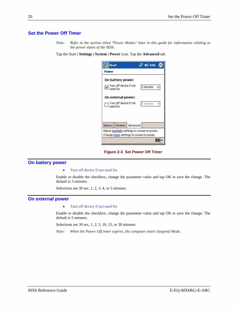
20 Set the Power Off Timer
MX6 Reference Guide E-EQ-MX6RG-E-ARC
Set the Power Off Timer
Note: Refer to the section titled "Power Modes" later in this guide for information relating to the power states of the MX6.
Tap the Start | Settings | System | Power icon. Tap the Advanced tab.
Figure 2-3 Set Power Off Timer
On battery power • Turn off device if not used for
Enable or disable the checkbox, change the parameter value and tap OK to save the change. The default is 3 minutes.
Selections are 30 sec, 1, 2, 3, 4, or 5 minutes.
On external power • Turn off device if not used for
Enable or disable the checkbox, change the parameter value and tap OK to save the change. The default is 5 minutes.
Selections are 30 sec, 1, 2, 5, 10, 15, or 30 minutes.
Note: When the Power Off timer expires, the computer enters Suspend Mode.

Accessing Files in Flash Memory 21
E-EQ-MX6RG-E-ARC MX6 Reference Guide
Accessing Files in Flash Memory
My Documents Folder Access: Start | Programs | File Explorer | My Device | My Documents Programs and files located in this folder are saved through a soft reset if they had been “saved” prior to resetting. They are not saved through a hard reset.
The IPSM Folder Access: Start | Programs | File Explorer | My Device | IPSM
Programs and files located in the IPSM folder are saved through a hard reset. Backed up registry settings are automatically restored after a hard reset.
When adding a new CAB file to the IPSM/AutoInstall folder:
1. First delete the RegBackup file in the IPSM folder.
2. Add the new CAB file, then press ESC + CTRL to perform a hard reset.
3. Reconfigure all settings, including the setting for the newly loaded CAB file.
4. Then tap Start (or the ) | Utils (or Power Tools) | RegBackup to save all settings.
CAB files stored in the AutoInstall folder within the IPSM folder are automatically unpacked following a hard reset.
If necessary, restore default registry settings by deleting the RegBackup file in the IPSM folder and then perform a hard reset.
After a Hard Reset (sometimes called Cold Boot) any programs that were not saved to the IPSM folder are lost and need to be reinstalled.
CAB File Program
LXEAVA.CAB Avalanche CE Manager
RFTERM.CAB RFTerm
JEODE.CAB Java
APPLOCK.CAB AppLock
POWERTOOLS_30 Power Tools Utilities
Saving Your Changes
To ensure that changes you make in control panels and other software, such as RFTerm, are saved to the archive registry and the active registry, follow the procedure below:
1. Make the change.
2. Reset (warm boot) the mobile device.
3. Test the change.
4. Tap Start (or the ) | Utils (or Power Tools) | RegBackup to permanently save the settings.
Refer to Chapter 3 “Physical Description and Layout”, section titled “Reset or Reboot” for more options.

22 Connect the Headset (Optional)
MX6 Reference Guide E-EQ-MX6RG-E-ARC
Connect the Headset (Optional)
The MX6 audio jack is located on the side of the unit next to the scan aperture and the SDA door (Secure Digital Access). The internal speaker is disabled when the audio jack is connected.
Figure 2-4 Audio Jack Location
Lift up the protective audio jack cover and insert the barrel end of the connector into the MX6 audio jack and push in firmly.
Note: The audio option draws power from the main battery pack.

Set The Audio Speaker Volume 23
E-EQ-MX6RG-E-ARC MX6 Reference Guide
Set The Audio Speaker Volume
Note: An application may override the control of the speaker volume. Turning off sounds saves power and prolongs battery life.
Version 7.03 Version 7.11 and &.13
Figure 2-5 Set the Audio Speaker Volume
The audio volume can be adjusted to a comfortable level for the user. The MX6 has an internal speaker and a jack for an external headset.
To adjust the volume, tap the Start | Settings | Personal tab | Sounds & Notifications icon.
As the volume scrollbar is moved between Loud and Silent, the computer beeps each time the volume increases or decreases in decibel range. The Volume icon in the system bar can also be used to adjust the system sound volume. Change settings and tap OK to save the changes.
Volume specific to primary events are selected using the options on the Volume or Sounds tab. You can also select / deselect sounds for key taps and screen taps and whether each is loud or soft.
Notification tones for events are selected using the options on the Notifications tab.

24 Adjust the Handstrap
MX6 Reference Guide E-EQ-MX6RG-E-ARC
Adjust the Handstrap
Note: The handstrap is not available on mobile devices with an integrated laser barcode scanner. See “Accessories” for holsters and cases designed for an MX6 laser barcode scanner without a handle or handstrap.
Figure 2-6 Handstrap
The MX6 has an integrated elastic handstrap that provides a comfortable, secure grip on a unit without a trigger handle. The handstrap is attached to the MX6 with a clip on the bottom panel. The handstrap should be disconnected from the bottom clip when the main battery is to be removed or replaced. The handstrap can be removed from the MX6 if desired.
Prior to adjusting the handstrap, pull down on the handstrap and insert the bottom assembly into the slot at the bottom of the MX6. Insure that both ends of the bottom assembly are secure.
Open the closed loop fastener tabs and adjust the handstrap for a comfortable, secure fit. Press the closed loop fastener ends together.

Enter Data 25
E-EQ-MX6RG-E-ARC MX6 Reference Guide
Enter Data
You can enter data into the MX6 through several different methods. The Scanner aperture provides barcode data entry, the combination USB/RS-232 or the IR port are used to input/output data, and the keypad provides text entry using the keypad.
MX6's with a touch screen use a stylus to input data, the COM ports and/or the keypad. A virtual keyboard is available in applications that expect keyed input.
Keypad Entry The keypad is used to manually input data that is not collected otherwise. Almost any function that a full sized computer keyboard can provide is duplicated on the keypad but it may take a few more keystrokes to accomplish a keyed task.
Almost every key has two or three different functions. The primary alpha or numeric character is printed on the key.
The Red or Blue keys are pressed when you want to use a 2nd key function. For example, when you press a Blue or Red key (the 2nd key), then press the key that has the desired second-function key. The specific 2nd character is printed above the corresponding key in either Red or Blue.
Please refer to “Appendix A - Key Maps” for instruction on the specific keypresses to access all keypad functions.
Stylus Data Entry Note: Always use the point of the stylus for tapping or making strokes on the display. Never use
an actual pen, pencil or sharp object to write on the touch screen.
The stylus performs the same function as the mouse that is used to point to and tap elements on a desk top computer. The stylus is used in the same manner as a mouse – single tap or double tap to select menu options, drag the stylus across text to select, hold the stylus down to activate slider bars, etcetera.
Hold the stylus as if it were a pen or pencil. Touch an element on the screen with the tip of the stylus then remove the stylus from the screen. The touch screen responds to an actuation force (touch) of 4 oz. (or greater) of pressure.
The stylus can be used in conjunction with the keyboard, integrated imager and an input/output device connected to one of the MX6's serial ports.
• Touch the stylus to the field of the data entry form to receive the next data feed.
• The cursor begins to flash in the field.
• The unit is ready to accept data from either the physical keypad, virtual keyboard, or integrated imager.

26 Enter Data
MX6 Reference Guide E-EQ-MX6RG-E-ARC
Using the Integrated Imager or Barcode Scanner Use the MX6 imager or barcode scanner to scan, decode, and store information from barcodes. The barcode data must be “read” into an application or field or the imaged data will be lost.
Do not pour, spray, or spill any liquid on the imager/scanner housing. The integrated imager and barcode scanner housing contains the circuitry, scanning motor, imager (and/or laser). Handle with appropriate care.
Read all cautions, warnings and labels before using the imager or barcode scanner.
Preparation These actions should be performed by the System Administrator before the MX6 is placed into daily service.
Edit Scanner/Imager Decoding Parameters (optional) See Chapter 6 “Scanner/Imager Parameter Setup” and “SCANCONFIG.INI” (Version 7.03, V 7.11 and V 7.13).
See Chapter 4 “System Configuration”, “Power Tools EZConfig Utilities” (Version 7.13 only).
The parameter settings in \IPSM\SCANCONFIG.INI document the LXE default scanner/imager decoding setup.
Scanner Setup Select Start | Settings | System | Scanner and set up scanner parameters before scanning a barcode.
Using the Imager / Barcode Scanner
Figure 2-7 Scan and Decode LEDs
To use the scan beam, aim the top of the MX6 at a barcode and press the Scan key or press the trigger on the handle. The MX6 scans as long as the key or the trigger is held down before the 5 second timeout occurs.
• Scan LED is on the right. When illuminated red, the MX6 is scanning a barcode. • Decode LED is on the left When illuminated green, the MX6 scan algorithm accepts the
barcode as a “good scan”.
The beam turns off automatically when a barcode is read successfully.

Enter Data 27
E-EQ-MX6RG-E-ARC MX6 Reference Guide
Distance from Label Large barcodes can be scanned at the maximum distance. Hold the imager closer to small barcodes (or with bars that are very close together).
Successful Scan When the scan is successful, the Scan LED turns green, then switches off, and the currently running application may produce a distinctive audible tone.
Unsuccessful Scan When the scan is unsuccessful, the Scan LED remains red until the 10 second timeout occurs or the Scan key/trigger is released. The currently running application may produce distinctive audible tones. Check the following:
• Check the barcode for marks or physical damage e.g. ripped label, missing section, etc.
• Try scanning test symbols of the same code type at different distances and angles.
• Is the aperture unscratched and unsoiled?
Scan Ranges Make sure the barcode is within the scanning range. The range of an imager and barcode scanner is dependent upon many outside influences including size of the barcode, quality of the barcode printing, material the barcode is printed on, and angle of the beam relative to the barcode label. Any of these factors may result in having to re-scan the label from a different distance or angle.
Engine Imager Decode Zone
SR 2.5 to 12.5 in. / 6.3 to 32 cm
Figure 2-8 Imager Decode Zones
Engine Scanner Decode Zone
5 mil barcodes from 2.75 to 7 in. / 0.07 to 0.17m HP
55 mil reflective barcodes from 5 to 50 in. / .13 to 1.26m
10 mil barcodes from 10 to 24 in. / 0.25 to .6m LR
100 mil reflective barcodes from 66 to 232 in. / 1.67 to 5.9m
13 mil barcodes from 18 to 39 in. / 0.45 to 1m ALR
100 mil reflective barcodes from 102 to 363 in. / 2.6 to 9.2m
Figure 2-9 Laser Decode Zones

28 Enter Data
MX6 Reference Guide E-EQ-MX6RG-E-ARC
Aiming at a Barcode Aim the beam aperture away from you, direct it at the barcode and press the trigger or button (as applicable) to scan. The Scan LED (scan indicators are located above the display) turns red to indicate the imager is on.
Imager
Adjust the aim so that the green aiming beam is centered on the barcode. The red light emitted from the imager must cover every bar and space on the barcode. When scanning a 2D Matrix barcode, the scan beam must cover the entire barcode.
Scanner Adjust the aim so that the red aiming beam is centered on the barcode. The red light emitted from the imager must cover every bar and space on the barcode. The scanner cannot read a 2D Matrix barcode.
Linear Barcode
Correct Scan Angle
Incorrect Scan Angles
2D Matrix Barcode
Figure 2-10 Scan Beam

Tethered Scanners 29
E-EQ-MX6RG-E-ARC MX6 Reference Guide
Tethered Scanners
Tethered scanners connect to the MX6 communication port or to the communication port on an MX6 vehicle cradle.
An adapter cable is required to attach a tethered scanner directly to the MX6 (MX6A056CBL3IND17D9M) or to the MX6 vehicle cradle (MX6A057CBL3IND9MD9M). See “Accessories”.
When using the 8500 series tethered scanners (LS3408), the tethered scanner Power Mode must be set to “Reduced Power Mode”. The default is “Continuous On”. Setting the scanner to reduced power mode will not impact performance of the 8500 series tethered scanners. Refer to the manufacturers user guide for instruction.
The MX6 Scan buttons have no effect on tethered barcode scanners (connected to a serial port). Tethered scanners read barcode scans only when the trigger on the tethered scanner is pressed.
To set the MX6 to use a tethered scanner, select Start | Settings | System | Scanner | COM1.
Tap the checkbox for "Tethered scanner on COM 1" to enable the tethered scanner. Scanner data can be configured for data rate, parity, stop bits and data bits using the COM1 tab.
Perform a warm boot after enabling the tethered scanner to power it on.

30 ActiveSync – Initial Setup
MX6 Reference Guide E-EQ-MX6RG-E-ARC
ActiveSync – Initial Setup
The following instructions relate to the initial setup of ActiveSync. Once a relationship between the MX6 and a desktop/laptop has been established, tap Start | Help | ActiveSync for help.
Note: You must establish a partnership between the MX6 and a desktop computer prior to running ActiveSync to connect using IrDA or Radio. The initial partnership must be done using direct serial or USB cable connection.
Install ActiveSync on Desktop/Laptop Go to the Microsoft Windows website ActiveSync Download | Install file location:
www.microsoft.com/downloads
and type ActiveSync in the Keywords text box. This process should locate the latest version of ActiveSync. Install ActiveSync 3.7 (or later) on the desktop or laptop computer before using ActiveSync to connect the desktop computer to the MX6.
Follow the instructions in the ActiveSync Wizard.
Check that Start | ActiveSync | Tools | Options has the correct connection selected. Refer to “Serial Connection” or “USB Connection”.
Note: By default, ActiveSync does not automatically synchronize all types of information. Use ActiveSync Options to specify the types of information you want to synchronize. The synchronization process makes the data (in the information types you select) identical on both your desktop computer and your device.
When installation of ActiveSync is complete on your desktop computer, the ActiveSync Setup Wizard begins and starts the following processes:
• connect your device to your desktop computer,
• set up a partnership so you can synchronize information between your device and your desktop computer, and
• customize your synchronization settings.
Because ActiveSync is already installed on the MX6, the first synchronization process begins automatically when you finish setting up your desktop computer in the ActiveSync wizard.
Troubleshooting If the MX6 is already in a docking cradle connected to a PC with a serial or USB cable, remove and reinsert the MX6 into the cradle.
If the MX6 is directly connected to a PC by RS-232 or USB cable, disconnect the cable from the MX6 and reconnect.
Serial Connection Select Start | ActiveSync | Tools | Options. At the PC tab, tap the Options button. Enable the “When cradled” checkbox. From the dropdown list, choose “57600 Default” and tap OK. This will set up the MX6 for serial connection.
Note: The default is 57600 baud.

ActiveSync – Initial Setup 31
E-EQ-MX6RG-E-ARC MX6 Reference Guide
USB Connection Select Start | ActiveSync | Tools | Options. At the PC tab, tap the Options button. Enable the “When cradled” checkbox. From the dropdown list, choose “USB Connection” and tap OK. This will set up the MX6 for USB cable connection.
IrDA Connection Note: You must establish a partnership with a desktop computer prior to running ActiveSync to
connect using IrDA. The initial partnership must be done using direct serial or USB cable connection.
The ActiveSync connection does true IrDA, not serial over IR, or TCP/IP (Winsock) over IR, like many infrared connections. Therefore, it is important to use a PC infrared interface which supports the handshaking needed for ActiveSync. This, unfortunately, precludes using many brands of laptops, which only use a simple infrared interface, even though they may call it IrDA.
Select Start | Settings | Connections | Beam. Enable the “Receive all incoming beams” checkbox.
This will set up the MX6 to use the Infrared port. To begin receiving an IR beam, tap the “Receive all infrared beams” hyperlink. Tap Cancel to abort.
Tap OK to return to the Connections tab.
Radio Note: You must establish a partnership with a desktop computer prior to running ActiveSync to
connect using the radio card in the MX6. The initial partnership must be done using direct serial or USB cable connection.
Once the relationship is established using the serial port, the ActiveSync link in the Start Menu gives a choice of connections, one of which is radio.
Select Start | ActiveSync. From the popup list, choose Network and then tap the Connect button.
Connect Connect the correct** cable to the PC (the host) and the MX6 (the client). Select "ActiveSync" from the Start Menu on the MX6.
Note: Run "Connect" when the "Get Connected" wizard on the host PC is checking COM ports to establish a connection for the first time.
Note: USB will start automatically when the USB cable is connected, not requiring you to select "Connect" from the start menu.
** Cables for initial ActiveSync Configuration:
MX6 - Charge/Comm Interface Cable, USB MX6A055CBLD17USB MX6 - Charge/Comm Interface Cable, RS-232 MX6A054CBLD17RS232 Cradle - USB Cradle to PC Interface Cable MX6A057CBL6USB Cradle - RS-232 Cradle to PC Interface Cable MX6A059CBL6RS232

32 ActiveSync – Initial Setup
MX6 Reference Guide E-EQ-MX6RG-E-ARC

E-EQ-MX6RG-E-ARC MX6 Reference Guide
Chapter 3 Physical Description and Layout
Hardware Configuration
System Hardware The MX6 hardware configuration is shown in the following figure.
Figure 3-1 System Hardware
Central Processing Unit The LXE MX6 CPU is a Intel Xscale PXA255 Processor running at 400 MHz. The operating system is Windows Mobile for Pocket PC resident in flash memory.
Note: LXE released the MX6 running Windows Mobile for Pocket PC in Fall 2004. All previously shipped MX6 devices have the Microsoft Pocket PC 2002 operating system. This guide is directed to the MX6 running Windows Mobile.

34 Hardware Configuration
MX6 Reference Guide E-EQ-MX6RG-E-ARC
Core Logic The MX6 supports the following I/O components of the core logic:
• One user accessible Secure Digital (SD) memory expansion card slot. • One InfraRed port. • One serial/USB port. • One Digitizer Input port (Touch screen).
System Memory On-board 64 MB RAM and 32MB non-volatile Flash contain the Windows Mobile operating system, hardware-specific OEM Adaptation Layer, device drivers, standard Windows Mobile applications and utilities. The operating system supports MFC, ATL and Visual Basic programming languages, TCP/IP and PPP network protocols. The Flash is configured as the primary boot device.
The mobile device has one Secure Digital card (SD) slot. The MX6 supports and auto detects up to 256MB of memory. SD cards are neither installed nor supported by LXE.
Video Subsystem The touch screen is a 3/8” (9.65cm) ¼ VGA 320 by 240 pixel TFT Reflective Active Color LCD. Backlighting is available for the display and the keypad, and is turned on and off with a keypress. The turn-off timing is configured through Start | Settings | System | Backlight icon. The display controller supports Microsoft Windows Mobile graphics modes.
The touch screen allows mouse functions (pointing and tapping on the display or Signature Capture) using an LXE approved stylus.
The color display is optimized for outdoor use but may also be used indoors. The color display has a CCFL (Cold-Cathode Fluorescent Lighting) front light.
The transflective color display appears to have a greenish hue when the unit is in Suspend.
Power Supply The LXE MX6 uses two batteries for operation. LXE strongly recommends keeping the MX6 connected to an external power supply when the MX6 is not in use.
• A replaceable Lithium-Ion (Li-Ion) 2000mAh battery pack. The battery pack recharges while in the MX6 with the computer connected to an external power source (powered cradle, AC/DC adapter, etc.) The main battery pack can be removed from the MX6 and inserted in a single charger or four-bay multi-charger.
• An internal 3.6V NiMH backup battery. The backup battery is charged directly by the main battery. The internal battery prematurely discharges if there is not at least a partially charged battery in the MX6. Full charging of the backup battery requires seven hours. The recharging of the backup battery is automatically controlled by the MX6 with an installed main battery pack AND connected to an external power supply. The backup battery must be replaced by qualified service personnel.
Audio Interface An interface is available for headset/microphone operation. When the headset is plugged into the audio port, the main speaker is disabled.

Hardware Configuration 35
E-EQ-MX6RG-E-ARC MX6 Reference Guide
Secure Digital Cards Note: When removing or installing Secure Digital (SD) cards, protect the MX6 internal
components from electrostatic discharge.
SD memory interface cards are used for expanded data storage. SD cards are neither installed nor supported by LXE. LXE recommends purchasing preformatted Toshiba® or Sandisk® SD cards.
SD Installation / Removal
Figure 3-2 Secure Digital Memory Interface Card Location
Equipment required: A Phillips screwdriver (not supplied by LXE)
• LXE recommends that installation/removal of cards be performed on a clean, well-lit surface.
• Anti-static protection is required when installing/removing cards. (Not supplied by LXE)
• If you anticipate keeping a card out of the MX6 for a long period of time place it in a static-free storage container. Store in an area that is protected from dirt, moisture, and electrostatic contact.
Note: The SD card is approximately the size of a postage stamp (32mm x 24mm). Make sure the work area is clean and uncluttered before removing the SD card from it’s packaging.
Installation
1. Tap the power key to place the MX6 in Suspend mode. Remove the main battery pack.
2. Using a screwdriver, loosen the SD Access Door on the left side of the MX6.
3. Remove the rectangular rubber protective seal over the SD card opening.
4. Set the door, protective seal and the screws aside.
5. Slide the SD Card, connector side first, into the slot until it seats. Use caution not to pull or snag any cables that may be in the vicinity of the card.
6. If the card is difficult to seat in the slot, remove the card, turn it around and re-install.
7. Place the access door back in the opening and secure with the screws.
8. Replace the main battery pack and perform a Soft reset.
Removal
Grasp the top of the Card and pull it straight upward to remove.
Use caution not to pull or snag any cables that may be in the vicinity of the card.

36 COM Ports
MX6 Reference Guide E-EQ-MX6RG-E-ARC
COM Ports
The MX6 supports two COM port options.
RS-232 Port, USB and Power Connection
(COM 1) IR Port (COM 3)
IrDA Port (COM 6) Figure 3-3 COM Ports
COM 1 port is always the 17-pin port on the base of the MX6. COM 1 port accepts RS-232, USB and AC power connectors.
The RS-232 port on the docking cradle is “connected’ to the MX6 when the MX6 is in the docking cradle. The docking cradle must be powered by an alternate AC or DC power source to enable communication.
The COM 3 / 6 port is always the IR port on the left side of the MX6. It is accessed as COM3 for Raw Infrared communication and as COM 6 for Infrared communication using IrDA protocol.
To use COM 3 for Raw IR communication, select Start | Settings | Connections | Beam and uncheck “Receive all incoming beams …”. This action disables IrDA protocol.

COM Ports 37
E-EQ-MX6RG-E-ARC MX6 Reference Guide
RS-232 Serial Port Serial connection is made through an RS-232 Port designated as COM port 1. The connector is a custom, industrial 17-pin male connector.
When seated in powered docking cradles, the MX6 receives power through this connection and the main battery is charged. If the docking cradle is connected to a desktop / laptop computer, this connector also transmits data.
The connection to the peripheral can be RS-232 or USB. The maximum RS-232 speed is 115kbps with seven baud rate settings. USB communication runs at 12 Mbps. This port also provides power out (to peripheral devices with special cable) at 500mA at 5V.
1 9
10 17
Figure 3-4 MX6 RS-232 Port
PIN SIGNAL PIN SIGNAL 1 + USB 10 - USB 2 PWR 11 USB DET 3 N / C 12 RI 4 N / C 13 DSR 5 N / C 14 RXD 6 N / C 15 RTS 7 GND 16 TXD 8 5V OUT 17 CTS 9 DTR

38 COM Ports
MX6 Reference Guide E-EQ-MX6RG-E-ARC
Integrated Imager or Scanner The MX6 has an integrated imager or an integrated laser scanner. The type of laser scanner engine is documented on the label inside the battery well. When there is no laser scanner engine listed, the MX6 has an integrated imager. Please refer to the “MX6 User’s Guide” for instruction.
Can be decoded by … Can be decoded by … Barcode Symbology Imager Scanner
Barcode Symbology Imager Scanner
Auspost x Int25 x x Aztec x ISBT x x BPO x JapanPost x Canpost x Maxicode x Codabar x x Mesa x Codablock x MicroPDF x Code11 x x MSI x x Code128 x x OCR x Code39 x x PDF417 x Code49 x Planet x Code93 x x Postnet x Composite x QR x DataMatrix x RSS x x DutchPost x TLC x EAN13 x x UPCA x x EAN8 x x UPCE0 x x IATA25 x x UPCE1 x x
Figure 3-5 Barcode Symbologies – Imager and Laser Scanner
Note: Please contact your LXE representative for availability of barcode symbologies not included in this list.
The Imager The MX6 Imager can be used to collect barcode data from any nearby compatible barcode label. Depending on the type of imager engine installed, size of the barcode, size of bars and spacing and quality of the barcode, the imager reads barcodes between 2.5 to 12.5 in. / 6.3 to 32 cm.
The integrated imager scans only when the Scan button is pressed or the scan trigger on the optional handle is pressed. The Scan LED illuminates during any integrated imager activation.

COM Ports 39
E-EQ-MX6RG-E-ARC MX6 Reference Guide
The Scanner The MX6 laser scanner can decode barcode data from any nearby compatible barcode label. Depending on the type of scan engine installed, size of the barcode, size of bars and spacing and quality of the barcode, the scanner reads barcodes between :
Engine Scanner Decode Zone
5 mil barcodes from 2.75 to 7 in. / 0.07 to 0.17m HP
55 mil reflective barcodes from 5 to 50 in. / .13 to 1.26m
10 mil barcodes from 10 to 24 in. / 0.25 to .6m LR
100 mil reflective barcodes from 66 to 232 in. / 1.67 to 5.9m
13 mil barcodes from 18 to 39 in. / 0.45 to 1m ALR
100 mil reflective barcodes from 102 to 363 in. / 2.6 to 9.2m
Figure 3-6 Laser Decode Zones
The integrated scanner scans only when the Scan button or trigger is pressed. The Scan LED illuminates during any scan engine activation.
Tethered Scanners LXE supports tethered scanners connected to the MX6’s bottom panel 17-pin RS-232 port and to the MX6 vehicle cradle.
See section titled “Tethered Scanners” in Chapter 2 “Getting Started” and the “Scanner” section in Chapter 4 “System Configuration”.
IR Port The InfraRed (IR) port provides a means of transferring information to a device with a similar port and the proper software. The IR port can be used to communicate with printers or a host computer with the use of an adapter.
The IR Port is specified as COM 3 and as COM 6 (depending on the type of IrDA communication) and is a bi-directional half-duplex infrared port. It supports the Slow IrDA (Infrared Data Access) PHY Layer standard that allows communication speeds up to 115k baud.
To use COM 3 for Raw IR communication, select Start | Settings | Connections | Beam and uncheck “Receive all incoming beams …”. This action disables IrDA protocol.
When sending data through the IR port to another MX6's IR port, make sure both units are in close proximity to each other. The IR operating envelope has a distance range of 2 cm (.79 inches) to 15 centimeters (6 inches) with a viewing angle of 30 degrees.

40 Reset or Reboot
MX6 Reference Guide E-EQ-MX6RG-E-ARC
Reset or Reboot
CAUTION LXE recommends that you always attempt a Soft Reset before initiating a Hard Reset. Once you initiate a hard reset, all applications are forcibly closed and working RAM and files are cleared. It is a good idea to store important data in Flash memory for this reason.
Soft Reset A soft reset closes all applications, clears the working RAM, and preserves the file system.
To initialize a soft reset press and hold the Control <CTRL> and Shift <SFT> keys for approximately 10 seconds.
Release the keys and the MX6 resets. The red and green LEDs blink for approximately three seconds.
After a Soft Reset
The Start screen appears. The custom settings in the registry are persistent. An installed RF Network program connects to the wired/wireless network system.
Hard Reset A hard reset is a complete reset in which all applications are forcibly closed and working RAM and files are cleared.
To perform a hard reset, press and hold the Control <CTRL> key and the Escape <ESC> key for approximately 3 seconds.
Note: The Start Menu will repeatedly appear and disappear and the keys will click repeatedly. This is intended to alert the user that a drastic action is about to occur. If the user presses and holds the <ESC> key and then presses the <CTRL> key, the flashing and clicking do not occur.
The red and green LEDs blink for approximately three seconds.
When the MX6 reboots, it will need to be configured once again. See the section titled “Quick Start”.
Caution: A hard reset erases all the data stored in RAM memory and all RAM installed applications.
See the section titled “The IPSM Folder” for a list of files that are saved over a hard reset.
Troubleshooting – Cold Boot/Hard Reset After a Hard Reset (sometimes called Cold Boot) any programs that were not saved to the IPSM folder are lost and need to be reinstalled.
LXE recommends that you always attempt a Soft Reset before initiating a Hard Reset. Once you initiate a hard reset, all applications are forcibly closed and working RAM and files are cleared. It is a good idea to store important data in Flash memory for this reason.
• The sequence of steps in “Getting Started” must be completed when the MX6 returns from a Hard Reset and when a new OS version is loaded.
• The radio, flash card, virtual keyboard and scanner parameters may also need to be reset after a hard reset.

Reset or Reboot 41
E-EQ-MX6RG-E-ARC MX6 Reference Guide
• As soon as the Certificate Authority (CA) certificate and server authentication certificates are downloaded to the expected location in the MX6, place a copy of the certificates in the IPSM folder. The certificates must be re-installed using CertAdd each time a hard reset occurs. When the current date has been set and the certificates installed, soft reset the MX6 to authenticate the supplicant (MX6 radio).
See Also: “Accessing Files in Flash Memory”.
Upgrading the Mobile Device OS To ensure that changes you make that involve upgrading drivers, adding CAB files or service packs or a new kernel are saved, follow the procedure below:
1. Delete REGBACKUP.HHP from the \IPSM folder.
2. Perform the appropriate Before-you-Proceed step from the table below:
Overwriting a CAB File If you are overwriting a CAB file with a new version, rename the existing CAB file or delete it.
Loading a new UTILS File
If you are going to be loading a new UTILS_XX.CAB file delete AUTOINSTALL.EXE, AUTORUN.INI, and AUTORUN.EXE from the \IPSM directory. Failure to do this may result in an AUTORUN.INI that does not match the installed kernel.
Installing a Service Pack If you are installing a service pack delete the older service packs.
Installing a new KERNEL If you are installing an update file containing a new kernel, delete the entire IPSM\AUTOINSTALL directory before proceeding.
3. Install software.
4. Hard reset (cold boot) the mobile device to clear the registry.
5. Configure the mobile device.
• See “Getting Started”.
• The radio, flash card, virtual keyboard and scanner parameters need to be reconfigured after a hard reset.
• Any programs that were not saved to the IPSM folder need to be reinstalled.
6. Soft reset the mobile device afterwards.
7. Verify the changes.
8. Tap Start (or the ) | Utils (or Power Tools) | RegBackup to permanently save the settings.

42 Power Modes
MX6 Reference Guide E-EQ-MX6RG-E-ARC
Power Modes
1. On 2. Tap Power key or the power
has failed 3. Power key, connect to AC
power supply, put into powered docking cradle, Scan key tap or trigger press.
4. Suspend 5. Backup battery and main
battery depleted 6. Off 7. Power On
Figure 3-7 Power Modes – On, Suspend and Off
On Mode
The Display When the display is On:
• the keyboard, touchscreen and all peripherals function normally • the display backlight is on until the Backlight timer expires • when the main battery is hot-swapped, the display is turned Off.
The MX6
New Unit After a new MX6 has been received, a charged main battery inserted, and the Power key tapped, the MX6 is always On until both batteries are drained completely of power.

Power Modes 43
E-EQ-MX6RG-E-ARC MX6 Reference Guide
Both Batteries Dead When the main battery and backup battery are drained completely, the unit is in the Off mode. The unit transitions from the Off mode to the On mode when a charged main battery is inserted, the MX6 is placed in a powered docking cradle, or external power is applied to the MX6. The unit performs a Hard Reset upon receiving power from a charged main battery pack.
LXE recommends connecting the MX6 to external power frequently during the work week to maintain a charge in the backup battery.
Main Battery Hot-swapped The MX6 automatically enters Suspend mode when the main battery is removed while the backup battery has adequate power to maintain the MX6 operating system. To wake the unit after the main battery has been replaced, press the Power key or the Scan key.
Suspend Mode The Suspend mode is entered when the unit is inactive for a predetermined period of time or the user taps the Power key. The MX6 does not enter Suspend when it is connected to AC power or when it is connected via ActiveSync unless it has been configured to do so. When connected to ActiveSync, the unit will enter Suspend if the Power key is tapped.
MX6 Suspend timers are set using Start | Settings | System | Power tab.
A Power key tap wakes the unit and resets the display backlight timers.
A touch screen tap or any key tap wakes the unit and resets the display backlight timers.
Placing the MX6 in a powered dock wakes the unit and resets the display backlight timers.
When the unit wakes up, the Display Backlight and the Power Off timers begin the countdown again. When any one of the above events occurs prior to the Power Off timer expiring, the timer starts the countdown again.
Off Mode The unit is in Off Mode when the main battery and the backup battery are depleted. Insert a fully charged main battery and press the Power key to turn the MX6 On. The unit performs a Hard Reset upon receiving power from a charged main battery pack.

44 The Keypads
MX6 Reference Guide E-EQ-MX6RG-E-ARC
The Keypads
35-key Keypad 56-key Keypad 56-key 5250 Keypad
Figure 3-8 The 35-key and 56-key Keypads
See also: Appendix A Key Maps.
Keys shown on the 35-key keypad that are inactive:
Contrast Up Contrast Down Send and End

The Keypads 45
E-EQ-MX6RG-E-ARC MX6 Reference Guide
Special Keys SCAN Key The SCAN key activates the image-taking and/or barcode decoding scan engine. It also “wakes” the MX6 from sleep mode.
Power Key The Power key puts the MX6 into and wakes the MX6 from Suspend mode.
Shift (SFT)
The Shift key toggles the keypad from upper case alphabet mode to lower case alphabet mode and back. Caps Lock may also be toggled by pressing the red modifier key followed by the Shift key or by double-tapping the Shift key. When Caps Lock is toggled on, the Shift key makes characters upper case; when it is toggled off, the Shift key makes keys lower case.
Enter (ENT)
The Enter key confirms data entry.
Escape (ESC)
The Escape key performs a cancel action.
Tab The Tab key moves the cursor to the next tab stop or the next control on a form.
Backlight
The Keypad Backlight key turns the keypad backlight on and off. It also turns the display backlight on if it is off. The keypad backlight turns off after 5 seconds if there is no keypad or touch screen activity. The Backlight key is located at the lower right of the 35-key keypad. It is located below the Power key on the 56 key keypad. The keypad backlight key is the only keypress used to turn the keypad backlight on and off.
Alpha Lock (ALPHA)
This key is included only on the 35-key keypad. Alpha defaults to numeric mode. The Alpha key toggles between the numeric and alphabetic modes.
Backspace (BKSP)
The Backspace key moves the cursor back one space for each time the key is pressed. It deletes characters as it moves.
Delete (DEL)
The Delete key deletes one character for each time the key is pressed.

46 The Keypads
MX6 Reference Guide E-EQ-MX6RG-E-ARC
Arrow Keys
Press the arrow (or cursor key) to move the cursor or highlighted text entry during a menu/list selection. In Normal mode:
• The Up arrow moves the cursor up one row or line.
• The Right arrow moves the cursor to the right one character.
• The Down arrow moves the cursor down one line or row.
• The Left arrow moves the cursor to the left one character.
Modifier Keys CTRL and ALT The Ctrl and Alt keys are located on the bottom row of the keypad. Functions of the Ctrl and Alt keys depend on the software application in use.
Note: Unlike the SFT key, Ctrl and Alt are not “sticky”. Press and hold Ctrl or Alt down while pressing the next key.
The blue and red keys (the blue key is to the left and red key is to the right) are used in conjunction with other keys to type the corresponding color-coded characters and functions. The Red and Blue keys modify only the next key pressed; these keys must be pressed and released before each key to be modified to the Blue or Red case.
Blue and red screen printing on the keypad match the left / right pattern of the blue and red keys. For example, press the Blue key and the U key to open the Start menu; press the Red key and the U key for the F21 function.
Keypress Sequences See Appendix A for key maps for all keypads.
Function Keys Function keys F6, F7 and F11 do not produce the standard windows messaging sequence. Instead they produce the following:
F6 WM_KEYDOWN wParam=0x60 WM_KEYUP wParam=0x60 F7 WM_KEYDOWN wParam=0x61 WM_KEYUP wParam=0x61 F11 WM_KEYDOWN wParam=0x62 WM_KEYUP wParam=0x62
In order to use these keys as function keys, applications must interpret the message sequences above.
Note: Use <CTRL>+<F1> key sequence to get function key F7, <CTRL>+<F5> key sequence to get function key F11. These “second key” functions bypass the standard windows messaging sequence described above for F7 and F11.

Touch Screen 47
E-EQ-MX6RG-E-ARC MX6 Reference Guide
Touch Screen
Figure 3-9 Touch Screen
The MX6 Touch Screen Display is a color LCD unit capable of supporting VGA graphics modes. Display size is 320 x 240 pixels in portrait orientation. The display covering is designed to resist stains. The touch screen allows signature capture and touch input. A pen stylus is included. The touch screen responds to an actuation force (touch) of 4 oz. of pressure (or greater).
When the color LCD unit is in Suspend mode, the reflective 256 color display appears to have a greenish hue.
The display is automatically turned off when the MX6 enters the Suspend state.
Display Backlight Timer When the Backlight timer expires the display backlight is turned off. The default value for the battery power and AC timer is 30 seconds.
When the display wakes up, the Backlight timers begin the countdown again.
Cleaning the Glass Display and Imager Aperture Keep fingers and rough or sharp objects away from the scan aperture and display. If the glass becomes soiled or smudged, clean only with a standard household cleaner such as Windex(R) without vinegar or use Isopropyl Alcohol. Do not use paper towels or harsh-chemical-based cleaning fluids since they may result in damage to the glass surface. Use a clean, damp, lint-free cloth. Do not scrub optical surfaces. If possible, clean only those areas which are soiled. Lint/particulates can be removed with clean, filtered canned air.

48 Speaker
MX6 Reference Guide E-EQ-MX6RG-E-ARC
Speaker
The speaker is located on the back of the MX6. The speaker has a loudness of at least 87 dB (1500 Hz) at 10 cm measured from the back of the unit. The Speaker volume is adjustable via the keypad or the Settings or by an application through the use of an API call. There are 6 distinct volume levels. The minimum volume level is 0 (no sound) with a default setting of 3. The volume sticks at maximum and minimum levels.
The speaker is disabled when a headset is plugged into the Audio Jack. The audio volume can be adjusted to a comfortable level for the user. The volume is increased or decreased one step each time the volume key sequence is pressed.
The default value for Sounds and Reminders is midrange Volume and all sounds enabled. When volume and sounds are enabled, speaker volume can be adjusted using the volume key sequence, if desired.
See section “Set the Audio Speaker Volume” in Chapter 2 for instruction.
Note: An application may override the control of the speaker volume. Turning off sounds saves power and prolongs battery life.

Battery 49
E-EQ-MX6RG-E-ARC MX6 Reference Guide
Battery
The MX6 computer is designed to work with a rechargeable Lithium-Ion (Li-ion) battery from LXE. Under normal conditions it should last approximately eight to ten hours before requiring a recharge. The more you use the scanner or the RF transmitter, the shorter the time required between battery recharges. The MX6 keeps date and time valid for a minimum of four days using a fully charged backup battery and a main battery that has reached the Low Warning point.
When the main battery has lost most of its charge, an icon of an “empty” or “half-empty” battery appears.
The MX6 retains data, during a main battery hot swap, for at least 5 minutes.
Note: New main battery packs must be charged prior to use. This process takes up to four hours in an LXE Multicharger and three hours when the MX6 is connected to external power through it's power jack.
See Also: Appendix C “MX6 Multicharger”.
Checking Battery Status Access: Start | Settings | System tab | Power
Figure 3-10 Check Battery Status
Important: This symbol is placed on the product to remind users to dispose of Waste Electrical and Electronic Equipment (WEEE) appropriately, per Directive 2002-96-EC. In most areas, this product can be recycled, reclaimed and re-used when properly discarded. Do not discard labeled units with trash. For information about proper disposal, contact LXE through your local sales representative, or visit www lxe com.

50 Handling Batteries Safely
MX6 Reference Guide E-EQ-MX6RG-E-ARC
Handling Batteries Safely
• Never dispose of a battery in a fire. This may cause an explosion. • Do not replace individual cells in a battery pack. • Do not attempt to pry open the battery pack shell. • Be careful when handling any battery. If a battery is broken or shows signs of leakage do
not attempt to charge it. Dispose of it using proper procedures.
Caution
Battery cells contain a chemical solution which burns skin, eyes, etc. Leakage from cells is the only possible way for such exposure to occur. In this event, rinse the affected area thoroughly with water. If the solution contacts the eyes, get immediate medical attention.
Caution
Lithium and Li-Ion batteries are capable of delivering high currents when accidentally shorted. Accidental shorting can occur when contact is made with jewelry, metal surfaces, conductive tools, etc., making the objects very hot. Never place a battery in a pocket or case with keys, coins, or other metal objects.
Main Battery Pack The main battery pack has a rugged plastic enclosure that is designed to withstand the ordinary rigors of an industrial environment. The main battery pack is a modular device and is the battery pack cover/case as well. It should never be disassembled. Exercise care when transporting the battery pack making sure it does not come in contact with excessive heat or any power source other than the LXE battery chargers, powered docking cradles or the MX6 unit.
When the main battery pack is properly installed in the unit it provides up to eight hours of operation depending upon operation and accessories installed. The battery pack is resistant to impact damage and falls of up to four feet to a concrete surface.
Under normal conditions it should last approximately eight hours before requiring a recharge. The more you use the scanner or the transmitter, the shorter the time required between battery recharges.
Battery Hot-Swapping When the main battery power level is low, the MX6 will signal the user with a warning dialog box on the display, a specific toolbar icon and a warning tone. The low battery warning notice and tones continue until the main battery is replaced, the battery completely depletes, or the MX6 is placed in a powered docking cradle.
You can replace the main battery by simply removing the discharged battery and installing a charged battery within a five minute time limit (or before the backup battery depletes).
When the main battery is removed, the MX6 automatically suspends, the display is turned off and the backup battery will continue to power the unit for at least five minutes. Though data is retained, the MX6 cannot be used until a new main battery pack is installed. After installing the new battery, the MX6 automatically transitions to the On state. Full operational recovery from Suspend can take several seconds while the radio (if installed) is reestablishing an RF link.
If the backup battery depletes before a fully charged main battery can be inserted, the MX6 performs a hard reset. Programs and data in RAM is lost. Press the Power key to turn the MX6 On after the hard reset.

Handling Batteries Safely 51
E-EQ-MX6RG-E-ARC MX6 Reference Guide
Low Battery Warning It is recommended that the main battery pack be removed and replaced when it's energy depletes. When the Low Battery Warning appears do an orderly shut down, minimizing the operation of any installed devices and insuring any information is saved that should be.
When the unit is in an ON state, a low battery warning dialog box appears on the display and a warning tone is emitted.
Note: Once you receive the Low Battery Warning, you have approximately 5 minutes to perform an orderly shutdown and replace the main battery pack before the unit powers off. The Low Battery Warning will transition to Suspend before the computer powers off.
Backup Battery The MX6 has a backup battery that is designed to provide limited-duration electrical power in the event of main battery pack failure. The backup battery is a 3.6V NiMH battery that is factory installed in the unit. The need for recharging of the backup battery is automatically detected and controlled by the MX6. The energy needed to charge the backup battery comes from the main battery. It takes several hours of operation before the backup battery is capable of supporting the operation of the computer. The duration of backup battery life is dependent upon operation of the MX6, it’s features and any operating applications.
External power connected to an MX6 (containing a battery pack) recharges the main battery pack and the backup battery. The MX6 can be directly connected to external power, or receiving power through the connector in a powered docking cradle.
Letting the backup battery become fully discharged causes the MX6 to lose all data in RAM. LXE recommends frequent MX6 connection to an external power source to maintain charge in the backup battery.
The backup battery is replaced by LXE.
Battery Maintenance Publication The LXE publication “Getting the Most from Your Batteries” is available on the LXE Manuals CD and is a single-source guide to battery management. The publication contains information about battery recharging, conditioning, and other pertinent issues. It is also available on the LXE ServicePass website.

52 Charging the Main Battery Pack
MX6 Reference Guide E-EQ-MX6RG-E-ARC
Charging the Main Battery Pack
Using the Four Bay Charger/Analyzer (Optional) Note: The Multicharger must be connected to an AC/DC power source before battery charging
can occur.
Figure 3-11 MX6 Multicharger
See Also: Appendix C “MX6 Multicharger”.
The four bay Multicharger has four slots that fully charge a main battery in four hours. The charging slots work independently to control the charging of individual battery packs.
The last slot on the right also functions as a battery analyzer/charger. It resets and re-calibrates a battery, then displays it’s resulting capacity. The process monitors changes in temperature, current, and voltage. The slot senses when a battery pack is fully charged and automatically switches to maintain the battery at full capacity indefinitely.
LXE recommends all MX6 battery packs be Analyzed on a monthly basis. Analyzing will reset the internal battery charge indicator circuit, "the gas gauge", as well as analyze the battery.
How To Charge a Spare Battery Pack
1. Insert the end of the battery without the locking tab into the charging slot.
2. Snap the battery into place with a hinging motion.
3. Once the battery is inserted, observe the Status LED to monitor the charging process.
The Status LED is orange while the battery is charging, and green when the charge cycle is complete.
How To Charge/Analyze a Spare Battery Pack
1. Insert the end of the battery without the locking tab into the right hand charge/analyze slot.
2. Snap the battery into place with a hinging motion.
3. Once the battery is inserted, press the Analyze button. Observe the Indicator LEDs to monitor the charge/analyze process.
The Status LED flashes orange during the analyze phase, illuminates solid green when the analyze cycle has completed. When the cycle is complete, the Indicator LEDs display the current battery capacity of the battery in the charge/analyze slot.

Docking Cradles 53
E-EQ-MX6RG-E-ARC MX6 Reference Guide
Charging a Battery Using the Desktop Docking Cradle Note: The cradle must be connected to an AC/DC power source before battery charging can
occur.
The Desktop Cradle has an Auxiliary Battery Well that is used to charge a single main battery pack in the charged desk mount docking cradle while at the same time the cradle can charge the battery in an MX6 in the charging/communication slot .
The MX6 unit does not have to be in the main charging well because each charger operates independently of the other. The spare battery will charge in four hours.
The cradle senses when a battery pack is fully charged and automatically switches to maintain the battery at full capacity indefinitely.
How To Charge a Spare Battery Pack
1. Insert the end of the battery without the locking tab into the bottom of the auxiliary well opening.
2. Snap the battery into place with a hinging motion.
3. Once the battery is inserted, observe the Aux Battery LED to monitor the charging process.
See the “MX6 Cradle Reference Guide” for further information.
Docking Cradles
Note: The “MX6 Cradle Reference Guide” contains docking cradle installation and further information.
The docking cradles give the MX6 the ability to communicate with a host computer and other equipment. The MX6 can be either On or in Suspend mode while in the cradles.
Using wall AC adapters or DC/DC converters, the docking cradle transfers power to the internal charging circuitry of the MX6 and, in turn, the MX6 recharges the main battery. The desktop docking cradle recharges both the MX6 main battery and an auxiliary battery at the same time.
The vehicle docking cradle uses a 12V cigarette lighter adapter or a bare wire 12-48V power supply to transfer power to the internal charging circuitry of the MX6 and, in turn, the MX6 recharges the main battery. A powered docking cradle gives the MX6 the ability to communicate with a host computer and other equipment.
A complete battery charge of the main battery pack and an extra battery pack using the desktop docking cradle takes less than four hours. The vehicle cradle completely charges the main battery in the MX6 is less than four hours.
The cradles require an external power source, before communications or battery charging is available.
When the desktop and vehicle cradles are receiving external power and the MX6 is properly seated in the charging bay, the DOCK LED is green. When the battery in the MX6 is charging the DOCK LED is green.

54 Docking Cradles
MX6 Reference Guide E-EQ-MX6RG-E-ARC
Indicators and LEDs
Powered Desktop Cradle Label Color Explanation
DOCK Solid Green MX6 is properly seated in the charging bay and the main battery in the MX6 is charging.
AUX Battery Orange The spare battery is charging. Green The spare battery has completed charging and is ready
for use.
COMM w/serial port Red Serial data is being sent to the MX6 from the host. Green Serial data is being sent from the MX6 to the host. Orange Serial data is being sent at high data rates.
COMM w/USB port Green USB connection is established with the host.
Powered Vehicle Cradle Label Color Explanation
DOCK Solid Green MX6 is properly seated in the charging bay and the main battery in the MX6 is charging.
COMM w/serial port Red Serial data is being sent to the MX6 from the host. Green Serial data is being sent from the MX6 to the host. Orange Serial data is being sent at high data rates.
Note: IrDA transmission from an MX6 to or from a docked MX6 does not require a powered cradle.
See Also: Chapter 4 – System Configuration, Sections titled “ActiveSync”, “Infrared Receive” and “Beam”.
See Also: Chapter 1 – Introduction, section titled “Accessories” for LXE certified cables.

E-EQ-MX6RG-E-ARC MX6 Reference Guide
Chapter 4 System Configuration
Introduction
There are several different aspects to the setup and configuration of the MX6. Many of the setup and configuration settings are dependent upon the optional features such as hardware and software installed on the unit. The examples found in this chapter are to be used as examples only, the configuration of your specific MX6 computer may vary. The following sections provide a general reference for the configuration of the MX6 and some of it’s optional features.
Note: When a new battery is installed in the MX6 for the first time (and when both batteries have been completely depleted), the Time and Date must be re-set.
Windows for Pocket PC
Access: Start | Settings | System tab | About
For general use instruction, please refer to commercially available Windows Mobile user's guides or the Windows Mobile on-line Help application installed in the MX6.
This chapter's contents assumes the system administrator is familiar with Microsoft Windows options and capabilities loaded on most standard Pocket PC devices and/or desktop computers.
Therefore, the sections that follow describe only those Windows capabilities that are unique to the LXE MX6 and it's Windows Mobile environment.
Installed Software
Note: Some standard Windows Mobile options require an internal or external modem connection. Modems are not available from LXE nor supported by LXE.
When you order an MX6 you receive the software files required by the separate programs needed for operation and wireless communication. The files are loaded by LXE and stored in subdirectories in flash memory (or RAM).
This section lists the contents of the subfolders and the general function of the files. Files installed in each MX6 are specific to the intended function and the operating system version of the MX6.
LXE recommends connecting the MX6 to an external power supply, placing it in suspend mode and recharging the main battery when the mobile device is not in use.
View System Information Access: (Version 7.03) Start | Utils | SysInfo (Version 7.11) Start | Utils | SysInfo (Version 7.13) Start | Power Tools | SysInfo
Use these menu options to determine registry settings for System Time, System Information (Hardware Revision, Kernel, Service Pack, Boot Loader Version, etc), DLL Version Information, System Parameters, Network and Radio Information, Files stored in the IPSM folder, Files automatically installed, Power status, Storage space used and available, System version information and Global Memory settings.

56 Installed Software
MX6 Reference Guide E-EQ-MX6RG-E-ARC
Installed Software
Note: Some standard Windows Mobile options require an internal or external modem connection. Modems are not available from LXE nor supported by LXE.
When you order an MX6 you receive the software files required by the separate programs needed for operation and wireless communication. The files are loaded by LXE and stored in subdirectories in flash memory (or RAM).
This section lists the contents of the subfolders and the general function of the files. Files installed in each MX6 are specific to the intended function and the operating system version of the MX6.
LXE recommends connecting the MX6 to an external power supply, placing it in suspend mode and recharging the main battery when the mobile device is not in use.
Software Load The software loaded on the MX6 computer consists of the Windows Mobile 2003 operating system, a hardware-specific OEM Adaptation Layer, device drivers, and utilities. The wireless drivers are stored in flash memory. During the hard reset process, the wireless drivers are loaded as well as any saved parameters. The software supported by the MX6 is summarized below:
Operating System • Microsoft Windows Mobile 2003 Software for Pocket PCs – Professional Edition
Terminal Emulation • LXE RFTerm (VT220, TN5250, TN3270)
802.11 SyChip radio
Integrated Imager or Laser Scanner Driver
Utilities
Power Tools (Version 7.13 only)
MX6 Demonstration Programs
LXE API Routines
JAVA (Optional) Installed by LXE. Files can be accessed by tapping Start | Programs | JEM-CE. Doubletap the EVM icon to open the EVM Console. A folder of JAVA examples and Plug-ins is also installed with the JAVA option. LXE does not support all JAVA applications running on the MX6.
LXE RFTerm (Optional) Installed by LXE. The application can be accessed by tapping Start | Programs | RFTerm. Please refer to “Terminal Emulation Setup” earlier in this guide for RFTerm quick start instruction. Refer to the “RFTerm Reference Guide” on the LXE Manuals CD for complete information and instruction.

Power Tools (Version 7.13 only) 57
E-EQ-MX6RG-E-ARC MX6 Reference Guide
AppLock (Optional) Installed by LXE. Application is setup by the Administrator by tapping Start | Settings | System | Administration. Please refer to Chapter 5 “AppLock” in this guide for complete information and instruction. Configuration parameters are specified by the AppLock Administrator for the mobile device end-user. AppLock is password protected by the Administrator. End-user mode locks the end-user into the configured application or applications. The end user can still reboot the mobile device and respond to dialog boxes. The administrator-specified application is automatically launched and runs in full screen mode when the device boots up.
WaveLink Avalanche (Optional) Installed by LXE. Enabler files are installed upon initial bootup and after a hard reset. The designation of the mobile device to the Avalanche CE Manager is LXE_MX6. See the section titled “WaveLink Avalanche Enabler” for features supported by this enabler.
Power Tools (Version 7.13 only)
LXE installs the Power Tools EZConfig Editor and EZConfig Client on an MX6 with Microsoft Windows Mobile Version 7.13 operating system. Power Tools simplify MX6 system tasks such as retrieving device information, customizing user interfaces, and working with the registry.
The Power Tools application consists of a .CAB file and network utilities in the system kernel. The Power Tools EZConfig editor can be run on a desktop/laptop PC and on the MX6.
• EZConfig Editor (MX6) – Located on the mobile device. Configuration files are viewed, imported, edited, saved and run on the mobile device.
• EZConfig Client (MX6) - The Client executable is stored in the /IPSM folder on the mobile device and is reloaded upon each Hard Reset.
• EZConfig Editor (PC) - Located on a desktop/laptop (PC). After editing and saving, configuration files are downloaded to the mobile device using an ActiveSync connection.
Note: Instructions for installing Power Tools and using the EZConfig Editor on a PC are not included in this reference guide.

58 Power Tools (Version 7.13 only)
MX6 Reference Guide E-EQ-MX6RG-E-ARC
Power Tools Panel Access: Start | Power Tools
Menu Option Function
BattMon Sets the LEDs to monitor battery power. See section titled “BattMon”.
Exit Tap to close the Power Tools Panel.
EZConfig Utilities Opens the EZConfig Utilities Panel. See section titled “Power Tools EZConfig Utilities”.
Hotkeys Activates button assignments. See section titled “Hotkeys”.
IPConfig Review and configure current IP configurations. Located in the Network Utilities folder. See section titled “IPConfig”.
Keyboard Status Activates the icon showing the status of the keypad mode in the taskbar. See section titled “Keyboard Status”.
Network Utilities Select this option when you want to use the IPConfig, Ping and Route utilities.
NoSIP Disables Soft Input Panel (SIP) presentation. See section titled “NoSIP”.
Ping Send a Ping to a network address (IP number). Located in the Network Utilities folder. See section titled “Ping”.
RASMan Setup the parameters for a mobile device when it needs to create a PPP connection with a RAS server. See section titled “RASMan”.
Reboot Tap this icon to initiate a Soft Reset or a Hard Reset. See section titled “Reboot”.
RegBackup Tap this icon to save (backup) the current registry settings to a file.
RegEdit Tap this icon to view/edit the currently in-use registry. See section titled “RegEdit”.
RegRestore Tap this icon to restore the last saved registry settings to the in-use registry.
Route Tap this icon to manage the routing table of all gateway entries. Located in the Network Utilities folder. See section titled “Route”.
Suspend Tap this icon to set the device in Suspend Mode. See section titled “Suspend”.
SysInfo Displays a text file containing the current hardware and software settings for the mobile device. See section titled “SysInfo”.

The Start Menu 59
E-EQ-MX6RG-E-ARC MX6 Reference Guide
The Start Menu
For general use instruction, please refer to commercially available Windows user's guides or the on-line Help application available on the MX6.
The Start menu appearance is similar to that of a hand held PDA. The default bootup screen is Today.
Tap Start (or the ) to display the Start menu. The Start menu is separated into sections:
• Start menu displays Quick Start Applications.
• Recently used Programs, e.g. Word, File Explorer, etc.
• Programs loaded on the mobile device.
• Settings which are split into Personal, System and Connections segments.
• Find or Help capability (access on the Start menu can be set by the user).
Start Menu Factory Default Settings Option Version 7.03 Version 7.11 Version 7.13 Today X X X ActiveSync X - - Calendar - X X Contacts X X X Demos X X X Inbox X - - Internet Explorer X X X Messaging - X X Power Tools - - X Notes X X - Tasks X X - Utils X X - Windows Media X X X File Explorer - - - Programs X X X Settings X X X RFTerm (option) - X - Find X - - Help X - - Figure 4-1 Start Menu Default Chart – Versions 7.03, 7.11 and 7.13
Note: The optional program, AppLock, is available through the Start | Settings | System | Administration menu path.

60 The Start Menu
MX6 Reference Guide E-EQ-MX6RG-E-ARC
Edit Start Menu Item List Access: Start | Settings | Personal | Menus Tap the checkboxes to enable (fill with a checkmark) or disable (remove the checkmark) for the applications to be displayed as Quick Start Applications in the Start Menu.
Figure 4-2 Edit Start Menu Item List
Create a new Menu by tapping the New Menu tab. Enable the “Turn on New button menu” checkbox. Make your selections from the list and tap OK or press Enter.
The new menu options appear when the New tab in the Taskbar is tapped.
Note: Up to seven programs are allowed on the Start Menu in Versions 7.11 and 7.13. Up to nine programs are allowed on the Start Menu in Version 7.03.

Programs 61
E-EQ-MX6RG-E-ARC MX6 Reference Guide
Programs
Access: Start | Programs
Help is always available at any stage – tap Start | Programs | Help. When working in a program, tap the question mark ( ? ) in the top right hand corner of the window for context sensitive help about the specific application. Not all programs have context sensitive help available. Tap OK or the ( X ) to close Help.
Installed Programs Access: Start | Programs
Program Version 7.03 Version 7.11 Version 7.13
ActiveSync - X X
Avalanche (Optional) - X -
Calculator X X X
Calendar X - -
Demos - X -
File Explorer X X X
Find - X X
Games X X X
Help - X X
LXE RFTerm (Optional) X X X
Meetinghouse AEGIS Client X X X
Meetinghouse Certificate Installer X X X
MSN Messenger X X X
Notes - X X
Pictures X X X
Pocket Excel X X X
Pocket MSN X X X
Pocket Word X X X
Tasks - X X
Utils X X X
Figure 4-3 Installed Programs Chart – Versions 7.03, 7.11 and 7.13
Note: The optional program, AppLock, is available through the Start | Settings | System | Administration menu path.

62 Programs
MX6 Reference Guide E-EQ-MX6RG-E-ARC
ActiveSync Access: Start | Programs | ActiveSync Requirement: ActiveSync version 3.7 (or higher) must be on both the host (desktop/laptop)
computer and the MX6 (client).
Using Microsoft ActiveSync version 3.7 or higher, you can synchronize information on your desktop computer with the MX6 and vice versa. Synchronization compares the data on your MX6 with your desktop computer and updates both with the most recent data.
Figure 4-4 Start ActiveSync on the MX6
• If the MX6 is already in a docking cradle connected to a PC, remove and reinsert the MX6 into the cradle.
• If the MX6 is connected to a PC by RS-232/USB cable, disconnect the cable from the MX6 and reconnect.
Check that Start | ActiveSync | Tools | Option has the correct connection selected (Serial or USB).
Note: By default, ActiveSync does not automatically synchronize all types of information. Use ActiveSync Options to specify the types of information you want to synchronize. The synchronization process makes the data (in the information types you select) identical on both your desktop computer and your device.
When installation of ActiveSync is complete on your desktop computer, the ActiveSync Setup Wizard begins and starts the following processes:
• connect your device to your desktop computer, • set up a partnership so you can synchronize information between your device and your
desktop computer, and • customize your synchronization settings.
Because ActiveSync is already installed on your device, your first synchronization process begins automatically when you finish setting up your desktop computer in the ActiveSync wizard.
After your first synchronization, look at Calendar, Contacts, and Tasks on your device. Notice that the same information from Microsoft Outlook on your desktop computer is now on your device,

Programs 63
E-EQ-MX6RG-E-ARC MX6 Reference Guide
and you didn’t have to type a word. Simply disconnect your device from your computer and you’re ready to go!
For more information about using ActiveSync on your desktop computer, open ActiveSync, then open ActiveSync Help and you can also tap Start | Programs | Help and view the help topic for this option.
Synchronizing from the MX6 You must have set up ActiveSync on your desktop computer and completed the first synchronization process before you initiate synchronization from your device using a connection process other than USB or serial.
To initiate synchronization from your device, tap Start, then ActiveSync to begin the process.
Note: If you have a wireless LAN card, you can synchronize remotely from your device.
Tap to connect and synchronize.
View synchronization status.
Tap to synchronize via IR or change synchronization settings.
View connection status.
Tap to stop synchronization.
Tap Start | Help for context-sensitive help.
Avalanche (Optional)
WaveLink Avalanche Enabler Enabler files are installed upon initial bootup and after a hard reset. The designation of the mobile device to the Avalanche CE Manager is LXE_MX6. The following features are supported by this enabler when used in conjunction with the Avalanche Manager.
Network parameter configuration is supported for:
• IP address: DHCP or static IP
• RF network SSID
• DNS hosts (primary, secondary, tertiary)
• Subnet mask
• Enabler update
Configuration change or software download is not supported in this version. Contact your LXE representative to check for release dates for these functions.
See Also: “WaveLink Avalanche for WIN OS User’s Guide”.

64 Programs
MX6 Reference Guide E-EQ-MX6RG-E-ARC
Calculator Access: Start | Programs | Calculator Exit the Calculator program by tapping the X at the top of the screen until the Today screen is displayed. Tap Start | Programs | Help and view the help topic for this option.
Calendar Access: (Version 7.03) Start | Programs | Calendar (Version 7.11 and 7.13) Start | Calendar
Exit the Calendar program by tapping the X at the top of the screen until the Today screen is displayed. Tap Start | Programs | Help and view the help topic for this option.
Demo Programs Access: (Version 7.03) Start | Demos (Version 7.11) Start | Programs | Demo (Version 7.13) Start | Demos
Demo Setup Use this option to enable a specific IP Address, Decode Port and Imaging Port for the Image Demo, Print Demo and Scan Demo.
Imager / Imaging / IQ Imaging Demo
Capture an image. (MX6 with Imager only.)
Print Demo Print a barcode over cable or IR connection. Scan Demo Scan an image or barcode. (MX6 with laser scanner only) Signature Capture Establish signature patterns for handwriting data entry using the stylus.
Note: Disable the internal scanner (Start | Settings | System tab | Scanner) when you want to run the Scan Demo or Image Demo program.
The Imager equipped MX6 has an Imaging Demo program. Doubletap the scan demo program icon on this menu to run the imager demo program.
Tap the Exit icon to leave Demos and return to the Start screen.
File Explorer Access: (All Versions) Start | Programs | File Explorer
Use this option to locate files in folders stored in the MX6. The default folder shown is “My Device”.
There are few changes in the Windows Mobile version of File Explorer as it relates to the general desktop PC Windows File Explorer options.
Find Access: (Version 7.03) Start | Find (Version 7.11 and 7.13) Start | Programs | Find
There are few changes in the Windows Mobile version of the Find program as it relates to the general desktop PC Windows Find or Search function. The SIP automatically appears when the Find program is opened.

Programs 65
E-EQ-MX6RG-E-ARC MX6 Reference Guide
Games Access: (All Versions) Start | Programs | Games Tap the game name icon to start a game. Tap X then tap OK to close the Games window and return to the Programs window. Tap Start | Programs | Help and view the help topic for this option.
Help Access: (Version 7.03) Start | Help (Versions 7.11 and 7.13) Start | Programs | Help
There are few changes in the Windows Mobile version of the Windows Help program as it relates to the general desktop PC Windows Help program. Tap OK to close Help.
Inbox (Version 7.03 only) This start menu option requires a connection to a mail server. There are few changes in the Windows Mobile version of Inbox as it relates to the general desktop Microsoft Outlook Inbox options. Tap Start | Help to access Inbox Help. ActiveSync can be used to transfer messages between the MX6 inbox and a desktop PC inbox.
Internet Explorer Access: Start | Internet Explorer
This option requires an active wireless connection and an Internet Service Provider. There are a few changes in the Windows Mobile version of Internet Explorer as it relates to the general desktop Microsoft Internet Explorer options.
Factory Default Settings Version 7.11 to 7.13 Version 7.03 General General Home page about:home Home page about:home Language Western European Save History for 30 days Memory Clear History Wait for user Save History for 30 days Delete files Wait for user Delete files Wait for user Security Advanced Cookies Allow cookies Cookies Allow cookies Clear Cookies Wait for user Warn when changing to
page that is not secure Enabled
Warn when changing to page that is not secure
Enabled Language Western European
LXE RFTerm (Optional) Access: Start | Programs | LXE RFTerm
Note: This program is installed by LXE.
Refer to “Terminal Emulation Setup” earlier in this guide. Refer to the “RFTerm Reference Guide” on the LXE Manuals CD for instruction.

66 Programs
MX6 Reference Guide E-EQ-MX6RG-E-ARC
Meetinghouse AEGIS Client Access: Start | Programs | Meetinghouse AEGIS Client icon Note: When the Client is running, tap the Meetinghouse icon in the toolbar to make changes.
Use this menu option to set LEAP parameters for the 802.11 radio connection.
There are three menu options in the toolbar: Client, View and Help.
Select Client | Configure to make changes to the client configuration.
When configuration changes have been made, a message “Please restart client in order for configuration changes to take effect” is displayed on the screen. Tap OK to acknowledge the message then tap Start | Utils (or Power Tools) | Reboot | Warm Boot to restart your device.
See Also: Chapter 7 “Wireless Network Configuration”.
AEGIS Client Icon Indicator The color of the icon indicates the status of the controlled ports.
Icon Color This color icon indicates that …
Green Authentication succeeded.
Yellow Authentication is in process.
Red Authentication failed.
If there is no yellow, red or green in the icon then either the ports are not being controlled by 802.1X, or there is no authentication activity on the controlled ports. The absence of yellow, red or green may also indicate that the network access server is not an 802.1X aware device.
Gray The port is not in use or is disabled. Either the Client isn’t running, or the port is not bound to the 802.1X protocol.
Orange
The port is associated, but there is no response to 802.11b packets. If using WEP without 802.1x authentication, this will be the final state when the connection is complete. If using 802.1x authentication, it is either a transient condition or can indicate that attempts to authenticate have timed out as there was no response to 802.1X packets.
Blue There is no 802.11b activity. The port may not be connected to an 802.1X-aware entity.
To use the client, a port must be configured and enabled. A protocol must be configured and started. These are separate operations. Please see your network system administrator to obtain the information necessary to configure the AEGIS client in order to provide network access.

Programs 67
E-EQ-MX6RG-E-ARC MX6 Reference Guide
Getting Started The AEGIS client is initially started from the start menu. Initially it will open on the Main screen. When closed, the client runs in the background and it’s icon is present in the system tray. The color of the icon indicates the state of the client authentication.
When Using LEAP With Meetinghouse Version 2.0.0 (or later) you must enable “Provide Encryption Key Dynamically” when using LEAP on the Aegis client.
When Using WEP If using only WEP, disable the Meetinghouse client and configure the WEP key in the radio utility:
Ver 7.03 Configure WEP key : Start | Settings | Connections tab | Connections tab | Pegasus Settings | Config tab.
Set AP Search Threshold to Medium using the Advanced Profile Settings screen.
Ver 7.11 and Ver 7.13 Configure WEP key : Start | Settings | Connection tab | 802.11b | Config tab.
Set AP Search Threshold to Medium using the Advanced tab.
When Using WPA To configure the radio for WPA functionality the Pegasus Settings/802.11b configuration tool is not used. All configuration is done with the Meetinghouse Aegis supplicant.
WPA instruction is located in Chapter 7 “Wireless Network Configuration” only.

68 Programs
MX6 Reference Guide E-EQ-MX6RG-E-ARC
Main Screen The Client's Main screen contains a list of controlled ports (NICs). The colored port icon on the left indicates the authentication state.
The Main screen contains menu bar buttons or tabs labeled Client, View, and Help. Selecting each tab will bring up a small menu. The Client tab controls the run state and access to protocol configuration. View tab controls the appearance of the main screen and access to the event log. Help tab allows access to the registration dialog, help, and version information.
Selecting the port(interface) brings up a menu which allows the port to be controlled and configured. The port can be enabled or disabled, and must be enabled to work. Port configuration is covered in Port Configuration. Delete removes a port from the list.
Figure 4-5 Client Menu
You manage ports on this screen.
The main screen contains a port status icon to the left of each port listed. The color of the icon indicates the status of the port.
The color of the icon changes as the port starts authentication, negotiates with the access point and/or authentication server, and then joins the network. As the network interface starts or stops, the color of the port icon and the status field in the Interface List updates to reflect the current state of the interface.
Doubletap the port to configure wireless networks and protocols.
Tap Configure in the Client menu to configure User, System and Server parameters.

Programs 69
E-EQ-MX6RG-E-ARC MX6 Reference Guide
Client Menu
Close Close the Client interface while leaving the client running. Start/Stop Start or Stop the configured authentication protocol on the selected port. After you
finish the initial configuration, tap the network interface and tap Start. If the port is already active, tap Stop first, then Start to force the program to read the new configuration file
Restart Same as Stop followed by Start. Tap this when you receive a notice to restart the client.
Configure Brings up the Protocol Configuration Dialog, which contains the identity and protocol values which apply to all the adapters used by the authentication engine.
Exit Exit the Client which terminates the client, which stops the 802.1x protocol. View Switch between Advanced and Standard view. Read the Event Log.

70 Programs
MX6 Reference Guide E-EQ-MX6RG-E-ARC
The Configure Menu Option
User tab Allows protocol selection and setting user credentials.
Version 7.03 only
Figure 4-6 Client Configuration – User tab
Profile Default. Add a profile using this option.
Identity The device ID supplied to the authenticator. It can be up to 63 characters long and is case sensitive. Password is required.
Authentication Type
Select the protocol to be used from the drop down box: MD5-Challenge, TLS/Smart Card, LEAP, TTLS, PEAP.
Password
The password for MD5, Phase 1 TTLS, PEAP and LEAP. Ask (New in V7.11) Configures the client to show a popup window asking user for credentials when authenticating not using tunneled protocols.
Use certificate When checked, it enables the use of the optional user certificates in TTLS and PEAP. Default is unchecked.
Change button Press to bring up certificate change dialog. Certificate
Display field Shows the familiar name of the certificate selected in the certification dialog.
Identity Identity for TTLS and PEAP phase 2. Default is Not Used.
Password Password for TTLS and PEAP phase 2.
Tunneled authentication
Protocol
Protocol to be used in the secure tunnel, selected from the drop down box. Options: - PEAP/MS-CHAP V2 - PEAP/GTS - EAP-TLS - Generic Token Card

Programs 71
E-EQ-MX6RG-E-ARC MX6 Reference Guide
System tab Contains parameters to set system level fields.
Version 7.03 Only
Figure 4-7 Client Configuration – System tab
Log Level The level of detail in the log messages. Errors has the least detail, debugging the most. Default is “Information”. The log file “log8021X.TXT” is written to the Windows directory by default. Tapping “View” on the AEGIS Client – Running screen opens a menu where selecting “Event Log” opens the log file for viewing.
Port Manager Timeout The time for the radio to wait without activity before entering an inactive state which will require a restart of the connection. Default is 10 seconds. When the Port Manager timeout has expired, a message is displayed on the screen. Tap OK to restart.
Disable Wireless Zero Config
Enabled
Save Credentials for (Minutes)
Default: 10 minutes. The period of time the client stores and reuses credentials the user entered in the popup window during authorization. (New in V 7.11)

72 Programs
MX6 Reference Guide E-EQ-MX6RG-E-ARC
Server tab Information used to verify a server certificate in TOS, TTLS or PEAP. The default is “Not Used”.
Use the parameters on this screen when debugging or assigning server certificates.
Figure 4-8 Client Configuration – Server tab
Do not validate server certificate chain
If enabled, the server certificate will not be validated. For debugging only.
Certificate issuer must be Select the CA which signed the server certificate, or "Any Trusted CA".
Allow intermediate certificates Allow unspecified certificates to be in the server certificate chain between the server certificate and the specified “Certificate issuer”.
Server name must be The server name, or a domain to which the server belongs, depending on which of the two fields below has been checked. This will be compared to the server certificate's Subject: CN field.
Server name must match exactly
When selected, the server name entered must match exactly the server name found on the certificate.
Domain name must end in specified name
When selected, the server name field identifies a domain and the certificate must have a server name belonging to this domain or to one of its sub-domains

Programs 73
E-EQ-MX6RG-E-ARC MX6 Reference Guide
Wireless Networks Tab Access: Start | Programs | Meetinghouse AEGIS Client icon
Highlight the Port and hold the stylus on the port name until the “right-mouse-tap” menu is displayed. Tap Configure.
Version 7.03 only
Figure 4-9 Configure Port Settings

74 Programs
MX6 Reference Guide E-EQ-MX6RG-E-ARC
Available networks
The radio automatically scans for available networks and their names are listed.
Configured networks
Select a configured network to change properties or tap Add to create a new wireless network.
Wireless Networks Tab Set the parameters for Network Access Points and underlying protocol.
Protocol Tab Configure common protocols that apply to any network the port connects to.
Available Networks Section
This section displays the networks the terminal recognizes as available to connect to. When the Client is first installed, there are no entries in the Available Networks list.
Scan Tap this button to see a list of networks broadcasting their availability.
Info Displays information about the selected network. Shows SSID, MAC address, channel, and RSSI for the radio. Shows setting of WPA mode or WEP for security.
Move to Configured
This button activates only after Scan has been tapped and available networks have been retrieved. In the list of networks retrieved, select the network you wish to connect to, and tap Move to Configured. This selects the network, which now appears in the Configured Networks section. Note: You can also attach to networks who are not broadcasting.
Configured Networks Section
This section displays the networks your device is connected to. This section enables you to add or remove networks as well as review and edit the properties of existing configured networks.
Default
When the Client is first installed, there is a Configured Network named "default" in the list. This profile has Associate with any network selected in its Properties selection screen. If you are going to be in a location with only one access point (or more than one access point that attaches to the same network), the default profile may be sufficient for you needs, without necessitating the selection of a specific network or networks. If default is last in the list, it can act as a wildcard should you be out of the range of your primary networks (which are listed first). Do not place default at the top or middle of the list because, if it is, connection to the other list entries will never be attempted.
Up Tapping this button moves a selected network up one place in the list.
Down
Tapping this button moves a selected network down one place in the list. Note: The order of the networks in this list is the exact order that connections will be attempted. The network listed first will be attempted first and so on. Place your primary networks first.

Programs 75
E-EQ-MX6RG-E-ARC MX6 Reference Guide
Add
Tap this button to manually add a network to the Configured Networks list if
• the access point does not broadcast its SSID or
• you are pre-configuring the client for an access point that is not currently in range.
Remove Tap this button to remove a selected network in the list.
Properties Tap this button to review the properties of a network selected in the list. This button opens the same network configuration screen as the Add button does; use it to edit network configuration properties.
Protocol Tab
Figure 4-10 Protocol Tab
Protocol Options
Authentication Timeout The period the radio will wait to receive a response from the access point. The default is 30 seconds.
Held timeout The length of time the client will remain in the held state after failing authentication. The default is 60 seconds.
Start timeout The period of time the client will remain in the connecting state before restarting from lack of response. The default is 30 seconds.
Number of start attempts Before the client gives up. It defaults to the authenticated state although there is no network connectivity. The default is 3 tries.
Interface Options
Display EAP Notifications
Enabled. This option allows informational messages from the access point to be displayed on the screen.
Renew IP Address Enabled. DHCP is used to obtain an IP address immediately after authentication.

76 Programs
MX6 Reference Guide E-EQ-MX6RG-E-ARC
Profile Info tab Factory Default Settings Profile Info Profile Info Network profile and network name Peer to peer group Ad Hoc mode disabled Associate with any available network
Disabled
Do active scan Enabled Authentication profile Default
Figure 4-11 Profile Info Tab
Network Profile Enter the name of this record. This is the name that appears in the Configured Networks list and, by default, is the same as the broadcast SSID. Note that there is nothing special about the name "default". You could configure any other record similarly and it would behave the same way.
Network Name This is the SSID of the access point. If the access point broadcasts its SSID, then this value may be derived from the Available Networks list. If the SSID does not broadcast, then you must manually enter the value here.
Peer-to-Peer Group (ad hoc mode)
Select this option to have two or more client workstations communicate with each other without the benefit of an access point. You should also select Do Active Scan and, in the WEP Management page, enable Use key for data encryption while entering a common key for both sides. WPA is not supported in this mode.
Do active scan Select this option whenever the access point (or client, for ad hoc mode) is not broadcasting its SSID.

Programs 77
E-EQ-MX6RG-E-ARC MX6 Reference Guide
Authentication Profile Select the Client Configuration (user) profile associated with this network. The drop-down list contains client profile names created in the User tab of the Client Configuration Area. To open the selected profile, select it in the drop-down list and tap View. The User tab opens displaying the profile details. If you tap OK (to save changes) or Cancel, you are returned to the Profile Info tab.
WEP Mgmt tab Factory Default Settings WEP Management tab Provide encryption key dynamically Enabled Use key for data encryption Disabled Use key to authenticate with AP Disabled
Figure 4-12 WEP Mgmt tab
Provide encryption key dynamically
This option is selected by default. If this option is selected, the other WEP settings on this page are disabled. To enter a custom WEP, de-select this option. The other fields become active.
Use key for data encryption Select this option to manually enter a WEP key to encrypt your data to the access point. You enter that key in the Key field below.
Use key to authenticate with AP
Select this option if your network does not support 802.1x authentication and you need to connect to the access point without username and password authentication. The key entered below is used to authenticate instead.

78 Programs
MX6 Reference Guide E-EQ-MX6RG-E-ARC
Key In this field, enter the WEP key: • ASCII - 5 or 13 characters • Hexadecimal - 10 or 26 characters. When the key entered is in the correct format, the screen changes to display the type - ASCII or Hexadecimal.
Key Index/Transmit Key The Key Index drop-down list contains the available keys. You may enter up to four keys for reception; the Client will try all four to find one that works with the access point. From the drop-down list, select the key to be used for transmission as well. If the key selected is the transmit key, the Transmit key box is checked. To change the transmit key, select another key and check the Transmit key box. The check box of the original transmit key will be automatically de-selected.

Programs 79
E-EQ-MX6RG-E-ARC MX6 Reference Guide
WPA Settings tab Factory Default Settings WPA Settings WPA Mode Disabled PSK pass-phrase Blank
Figure 4-13 WPA Settings tab
WPA Mode This drop-down list contains the following options: • Disabled - Do not enable WPA mode. This is the default selection. • WPA 802.1x - Enable WPA and obtain key information through the 802.1x protocol. • WPA PSK - Enable WPA with Pre-Shared Key (PSK) information entered in the field below. This mode is used if the 802.1x protocol is not being used for authentication.
PSK pass-phrase This field activates if you select WPA PSK in the WPA Mode drop-down list. Enter between 8 and 63 characters for your pass phrase. Asterisks appear as you type for increased security.

80 Programs
MX6 Reference Guide E-EQ-MX6RG-E-ARC
Meetinghouse Certificate Installer Access: Start | Programs | Meetinghouse Certificate Installer
Certificate Requirements During configuration, you may have specified one or two certificates to use during the authentication process. The specified identity should match the Issued to field in the certificate and should be registered on the authentication server that is used by the authenticator. In addition, your certificate must be valid on the authentication server. This requirement depends on the authentication server and generally means that the authentication server must know the issuer of your certificate as a trusted Certificate Authority.
If the selected certificate does require a password or pass phrase to decode the private key, enter this value in the “Certificate Pass Phrase” field. This value will be encrypted when the configuration is saved. However, on some systems, there may not be a certificate. If that is the case, you can use the section below as a primer on OS X certificate management.
About CertAdd
CertAdd is a stand-alone utility included with the Client that allows certificates to be selected and installed on a Windows Mobile device.
Installing Certificates with CertAdd
Client or Certificate Authority (CA) certificates can be imported from *.cer (same as *.der), *.p7b, or *.pfx files.
1. Download the certificate file to the My Documents folder. The location isn’t critical, although you may want to create a standard folder for consistency.
2. Go to Start | Programs | Meetinghouse Certificate Installer. The opening screen is displayed. All valid certificate file types located in the My Documents folder appear in the list.
3. Tap and hold on a certificate in the list. A pop-up appears asking if you want to install the certificate.
4. Tap OK. The certificate is loaded into the correct certificate store.
Figure 4-14 Installing Certificates
Programs 81
E-EQ-MX6RG-E-ARC MX6 Reference Guide
MSN Messenger Access: (All Versions) Start | Programs | MSN Messenger
There are few changes in the version of MSN Messenger as it relates to the general desktop PC Windows MSN Messenger application. Tap Start | Programs | Help and view the help topic for this option.
Notes Access: (Version 7.03) Start | Notes (Versions 7.11 and 7.13) Start | Programs | Notes
Create a note using written and typed text, drawings, and recordings. The notes can be sent to others through e-mail, Infrared and ActiveSync with a desktop PC. Tap Start | Programs | Help and view the help topic for this option.
Pictures Access: (All Versions) Start | Programs | Pictures
The capabilities of this option are similar to those for Pictures on a desktop/laptop PC. An ActiveSync connection is required before pictures can be moved from the PC to the mobile device. Tap Start | Programs | Help and view the help topic for this option.
Pocket Excel Access: (All Versions) Start | Programs | Pocket Excel
The capabilities of this option are similar to those for Microsoft Office Excel on a desktop/laptop PC. An ActiveSync connection is required before Excel files can be moved from the PC to the mobile device and back again. Tap Start | Programs | Help and view the help topic for this option.
Pocket MSN Access: (All Versions) Start | Programs | Pocket MSN
The capabilities of this option are similar to those for Microsoft MSN on a desktop/laptop PC. Tap the icon to subscribe to MSN services on the MX6: MSN Messenger, MSN Hotmail, Alerts, and Mobile Web. Select Tools | Options to set Internet Explorer parameters when connected to the Internet using Pocket MSN. An ActiveSync connection and Internet access is required before a connection can succeed. Tap Start | Programs | Help and view the help topic for this option.

82 Programs
MX6 Reference Guide E-EQ-MX6RG-E-ARC
Pocket Word Access: (All Versions) Start | Programs | Pocket Word
The capabilities of this option are similar to those for Microsoft Office Word on a desktop/laptop PC. An ActiveSync connection is required before Word files can be moved from the PC to the mobile device and back again.
PocketWord documents are saved with a .PWD extension instead of .DOC extension although they can be saved as .RTF or .DOC files on the MX6. Microsoft Word templates (.DOT files) are converted to Pocket Word templates (.PWT). When ActiveSync transfers .PWD files to the desktop from the MX6, the file is converted to .DOC files by ActiveSync.
Tap Start | Programs | Help and view the help topic for this option.
Tasks Access: (All Versions) Start | Programs | Tasks OR Start | Tasks
The capabilities of this option are similar to those for Microsoft Tasks on a desktop/laptop PC. An ActiveSync connection is required before Tasks can be moved from the PC to the mobile device and back again. Tap Start | Programs | Help and view the help topic for this option.
Utils Access: (All Versions) Start | Programs | Utils
Tap the Utils icon to access the IPConfig, Ping and Route programs.
IPConfig See section titled “MX6 Utilities”, subsection “IPConfig” for explanation and instruction.
Ping See section titled “MX6 Utilities”, subsection “Ping” for explanation and instruction.
Route See section titled “MX6 Utilities”, subsection “Route” for explanation and instruction.

MX6 Utilities 83
E-EQ-MX6RG-E-ARC MX6 Reference Guide
MX6 Utilities
Access: (Version 7.03 and 7.11) Start | Utils (Version 7.13) Start | Power Tools
Utility Version 7.03(Start : Utils)
Version 7.11 (Start : Utils)
Version 7.13 (Start : Power Tools)
BattMon X X X
Exit X X X
EZConfig Utilities - - X
Hotkeys X X X
IPConfig X X -
Keyboard Status - X X
Network Utilities - - X
NoSIP X X X
Ping X X -
RASMan X X X
Reboot X X X
RegBackup X X X
RegEdit X X X
RegRestore X X X
Route X X -
Suspend X X X
SysInfo X X X
Figure 4-15 MX6 Utilities
BattMon Access: (Version 7.03 and 7.11) Start | Utils | BattMon (Version 7.13) Start | Power Tools | BattMon
BattMon sets the LEDs to monitor battery power.
Tap the BattMon icon. Once it is running, tap the BattMon icon in the taskbar to view battery charge status. The green (left) Scan LED blinks as the main battery is charging and is solid when the battery is fully charged.

84 MX6 Utilities
MX6 Reference Guide E-EQ-MX6RG-E-ARC
EZConfig Utilities Access: (Version 7.13) Start | Power Tools | EZConfig Utilities Tap this option to open the EZConfig application. There are two major components; EZConfig Editor and EZConfig Client. The Editor allows the user to create and modify configuration files that can be downloaded to and then used to configure another MX6 using the same options as the first MX6. The Editor can also generate barcodes from configuration files.
The EZConfig Client decodes the barcodes generated by the EZConfig Editor on the PC. The client executable is stored in the \IPSM folder.
Power Tools EZConfig Utilities are documented at the end of this chapter.
Note: Instructions for installing Power Tools and using the EZConfig Editor on a PC are not included in this reference guide.
Menu Option Description
Autorun Autorun allows applications to be launched based on conditional situations including the return code of another application launched previously and specific characteristics of the individual MX6.
DemosMenu Use this option to program the contents of the Demos main window.
DeviceConfig The DeviceConfig file contains mobile device configuration settings and is stored in the \IPSM folder.
EZConfig Menu Use this option to change the values in the Settings and MenuEntries section of the EZConfig Menu.
ImageDemo Use this option to view/change the imaging parameter setup.
Network Menu This option allows you to set the menu options and parameters when using the IPConfig, Ping and Route applications. See Start | Programs | Utils.
Power Tools Menu Determine which menu items display when the Power Tools menu is selected. The option to hide the Power Tools menu can be set using this file.
PrintDemo Menu Set up the parameters for the Print Demo menu item located at Start | Demos.
RASMan Setup the parameters for a mobile device when it needs to create a PPP connection with a RAS server.
RFSettings Use this option to view/change the RF Settings parameter default values.
Scandemo Set up the parameters for the Scan Demo menu item located at Start | Demos.
SetDevice Info Create the information that displays in the About panel in Start | Settings.

MX6 Utilities 85
E-EQ-MX6RG-E-ARC MX6 Reference Guide
Hotkeys Access: (Version 7.03 and 7.11) Start | Utils | Hotkeys (Version 7.13) Start | Power Tools | Hotkeys
Activates button assignments. Hotkeys are created using the Button applet. Tap the Hotkey icon to initialize the hotkey Button settings. Tap the icon again and select Yes to turn it off.
See Also: Start | Settings | Personal | Buttons.
IPConfig Access: (All Versions) Start | Programs | Utils | IPConfig (Version 7.03 and 7.11) Start | Utils | IPConfig (Version 7.13) Start | Power Tools | Network Utilities | IPConfig
Factory Default Settings Input Adapter nnnnnn Pegas1 Output Display Blank About Ipconfig Copyright
Figure 4-16 Utility Program – IP Config
Allows you to manually review and configure current Internet Protocol (IP) configurations. Online help is not available for this menu option. Tap X to close this window.
Adapter This drop-down list contains the network adaptors currently installed. All fields and buttons on this screen pertain to the adapter selected in this drop-down list.
Release the IP address button
Pressing this button changes the MAC address, sets the IP address to 0.0.0.0 and sets the Subnet mask to 0.0.0.0 as well as clearing out the Gateway data.
Renew the IP address button
Pressing this button renews the MAC address, IP address, Subnet Mask and Gateway data.
Display full configuration button
Pressing this button displays the Windows IP configuration for the 802.11 card and adapter in the Output window.
The Output window automatically opens when the Display full configuration button is tapped. The About tab displays description and version information about IPConfig.

86 MX6 Utilities
MX6 Reference Guide E-EQ-MX6RG-E-ARC
Keyboard Status Access: (Version 7.03 and 7.11) Start | Utils | Keyboard Status (Version 7.13) Start | Power Tools | Keyboard Status
Activates the icon showing the status of the keypad mode (alpha or numeric) in the taskbar.
A “1” icon is displayed when in numeric mode, and an “A” icon is displayed when in alpha mode. An icon is also added to the Taskbar, “1/A” icon. When this icon is tapped, a menu pops up.
The menu contains About, Settings, Enable and Exit options that can be used to control the Keyboard Status utility. Settings allows you to assign an Event Notification to the changing condition of the Keyboard status.
Network Utilities Access: (Version 7.13 only) Start | Power Tools | Network Utilities
Select this option to open the Network Menu when you want to use the IPConfig, Ping and Route utilities. Tap the Return icon to go back to the Power Tools panel.
NoSIP Access: (Version 7.03 and 7.11) Start | Utils | NoSIP (Version 7.13) Start | Power Tools | NoSIP This utility disables the SIP (Soft Input Panel) icon that is displayed on the bottom half of the screen. It also disables the popup SIP for every application.
For example, when you run Pocket Word and the focus is on the new document screen, the SIP keypad usually pops up at the bottom of the screen. After running NoSIP, the SIP keypad is not displayed in this mode. After running the NoSIP utility, an icon is added to the taskbar to allow the user to re-enable the SIP.

MX6 Utilities 87
E-EQ-MX6RG-E-ARC MX6 Reference Guide
Ping Access: (All Versions) Start | Programs | Utils | Ping (Version 7.03 and 7.11) Start | Utils | Ping (Version 7.13) Start | Power Tools | Network Utilities | Ping
Factory Default Settings Input Destination Blank Timeout (ms) 1000 Send buffer size 32 Send count 4 Infinite Disabled TTL Blank TOS Blank Rec. route for count hops Blank Timestamp route Blank Don’t fragment Disabled DNS address required Disabled Output Display Blank About Copyright
Figure 4-17 Utility Program - Ping
This utility sends a Ping to an IP address. Tap X to close this menu option. Help is not available for this option.
Pinging sends out an echo request to a specific computer on the network. Use Ping to check communication links or verify whether the specific Ping contains three tab windows: Input, Output, and About. On the Input tab, you enter and send packet information to the server. On the Output tab, you review the response.
Tap Execute on the Input tab to execute the IP address ping. Tap the Stop button to end the Ping activity.
Using the Ping Input Tab Parameters
Field Description
Destination Enter the ping destination.
Timeout (milliseconds) Enter the timeout time in millisecond intervals; 1000 is the default.
Send buffer size Indicate the buffer size for sending; 32 is the default.
Send count Indicate the count for sending; 4 is the default. Check Infinite to make the send count infinite.
TTL Short for Time To Live, this is the maximum amount of time a packet is allowed to travel through the network before it is discarded.

88 MX6 Utilities
MX6 Reference Guide E-EQ-MX6RG-E-ARC
Field Description
TOS Enter the Type of Service (TOS); it should be eight bits broken into five subfields.
Rec route for count hops
Enter the number of hops to record in the IP header; 1–9. This field traces the route of the packets for each hop.The hop count is the number of network devices between the starting node and the destination node that an IP packet hits while traveling over a network. The number of hops is recorded in the IP header.
Timestamp route Enter the number of timestamps to record for each hop; 1–4 The timestamp is the packet’s arrival time at each hop.
Don’t fragment Check this box if you don’t want the packet to fragment during routing.
DNS address required Check this if you want the domain name server to be part of the route path.
Execute Click Execute to send the ping. The Output tab displays the response.
Reading the Ping Output Tab Display
After you enter the IP information on the Input tab and click Execute, the Output tab appears and begins displaying the ping results.
You can click the Stop button at any time to stop the ping. Any errors encountered display on the screen. When the Ping process is complete or if you stop the ping at any point, ***Ping Stopped *** displays.
The About tab displays description and version information about Ping.

MX6 Utilities 89
E-EQ-MX6RG-E-ARC MX6 Reference Guide
RASMan Access: (Version 7.03 and 7.11) Start | Utils | RASMan (Version 7.13) Start | Power Tools | RASMan
Setup the parameters for a mobile device when it needs to create a PPP connection with a RAS server. Help is not available for this option.
RASMan establishes a PPP (Point-to-Point Protocol) connection with a RAS server.
To Enable RASMan 1. Tap Start | Power Tools. The Power Tools Main Window appears.
2. Tap the RASMan icon once . The PPP connection is established according to the settings established RASMan configuration file.
Note: To start RASMan automatically after each hard reset, enable the RASMan Program section in the Autorun Configuration File.
To Disable RASMan Tap Start | Power Tools and tap the RASMan icon again.
OR
Tap the RASMan icon to open the Command bar menu and tap Exit.
RASMan Command Bar Menu When RASMan is enabled, the RASMan icon appears in the Command bar at the bottom of the Today screen. Tap the icon to open the Command bar menu.
Menu Item Selecting this item …
Auto Connect This item is selected by default. It means that the mobile device is connected to the RAS server via PPP.
Connect Re-establishes the PPP connection if it was disconnected.
Disconnect Disconnects the PPP connection.
About Displays version and description information about RASMan.
Exit Disables RASMan; the icon no longer appears in the Command bar.

90 MX6 Utilities
MX6 Reference Guide E-EQ-MX6RG-E-ARC
RASMan Configuration File RASMan application settings are stored in the Settings section of the \IPSM\RASMan.EXM file. See “EZConfig Editor” for instructions on changing the values in the RASMan configuration file.
Key Description Valid Values
AutoConnectOnDock Controls an automatic RASMan connection when the terminal is docked and removed from the communication peripheral. Default value: 1
0=Disabled; the RASMan connection must be launched manually. 1=Enabled; RASMan connects when the terminal is docked in the cradle and disconnects with the terminal is removed.
Debug Enables and disables the creation of a debug log file. Default value: 0
0=Disabled; no log file 1=Enabled; Creates a log file of RASMan activity in the \IPSM folder.
AutoConnectOnStartup Controls the automatic connection when RASMan is started. Default value: 1
0=Disabled; the PPP connection is not established when RASMan is started. 1=Enabled; the PPP connection is established when RASMAN is started.
Connectoid Indicates the connection RASMan should use. Default value: `USB Connection
`USB Connection `115200 Default `19200 Default `38400 Default `57600 Default Note: These values must be typed in exactly as they appear here.
CommandLine Command to execute on a successful connection. Default value: Empty
Leave empty if no action is required.
CommandArgs Command arguments for the CommandLine setting. Default value: Empty
Leave empty if no action is required.
ConnectDelay Specifies the amount of time to wait before establishing the PPP connection after RASMan is started. Default value: 2000 (milliseconds)
Enter values in milliseconds.

MX6 Utilities 91
E-EQ-MX6RG-E-ARC MX6 Reference Guide
Key Description Valid Values
DisableActiveSync Disables the ActiveSync connection when RASMan is running. Default value: 1
0=Disabled; ActiveSync runs while RASMan is running. 1=Enabled; the ActiveSync connection is disabled while RASMan is running.
Retry Specifies the retry count. Default value: 10
RetryDelay Specifies the retry delay. Default value: 1000 (milliseconds)
Enter values in milliseconds.
ShowStatus Enables and disables the appearance of status dialog boxes. Default value: 1
0=Disabled; status dialogs do not appear. 1=Enabled; status dialogs do appear.
StopOnCriticalError Forces RASMan to stop running when a critical error occurs. Default value: 1
0=Disabled; RASMan continues to run when a critical error occurs. 1=Enabled; RASMan stops running when a critical error occurs.
Reboot Access: (Version 7.03 and 7.11) Start | Utils | Reboot (Version 7.13) Start | Power Tools | Reboot
Tap this icon to initiate a Warm or Cold Boot using the touch screen, as opposed to the keypad commands. Tap X to close the decision box without rebooting.
Warm Boot (Soft Reset) A warm boot closes all applications, clears the working RAM and preserves the file system.
Or
Press the CTRL and SFT keys at the same time for approximately 10 seconds.
Cold Boot (Hard Reset) A cold boot forcibly closes all applications, working RAM and files are cleared and the device’s parameters are reset to factory defaults (or the last saved registry settings).
Or
Press the CTRL and ESC keys at the same time for approximately three seconds.

92 MX6 Utilities
MX6 Reference Guide E-EQ-MX6RG-E-ARC
RegBackup Access: (Version 7.03 and 7.11) Start | Utils | RegBackup (Version 7.13) Start | Power Tools | RegBackup
To ensure that the most current registry settings are backed up, LXE recommends warm booting the mobile device prior to backup up the registry.
1. Perform a warm boot by pressing the CTRL key and SFT key for approximately 10 seconds.
2. When the device has rebooted, follow the “Access” path for your OS version.
3. Tap the RegBackup icon once. The registry starts backing up and a message is placed on the screen.
4. When the message disappears from the screen, the backup is complete, and a RegBackup file has been created in the \IPSM folder.
Note: By default, the RegBackup.reg file loads after a cold boot.
RegEdit Access: (Version 7.03 and 7.11) Start | Utils | RegEdit (Version 7.13) Start | Power Tools | RegEdit
LXE recommends RegBackup be run first and that changes to the registry be made c a r e f u l l y as there is no Edit/Undo capability in RegEdit and any changes made take effect as soon as the registry is closed.
Tap this icon once to begin editing the current registry. Tap File | Exit to save any registry changes and exit the RegEdit utility.
RegEdit opens to a split-pane window with a collapsible menu in the top half. This is the top level of the registry; it cannot be edited, copied, pasted or renamed.
Tap the + sign to expand menu options and the – sign to close them. The following categories are available: HKEY_CLASSES_ROOT, HKEY_CURRENT_USER and HKEY_LOCAL_MACHINE.
The Soft Input Panel is available when editing the Registry.
When a registry entry in the top half of the screen is tapped, the registry entry data appears in the lower half of the screen, showing the Value Name and Value Data.
1. Navigate to the registry entry that is to be viewed or changed and double-click on the data in the Value Data field. The Edit Value window pops up.
2. The Value Name cannot be changed.
3. In the Value Data field, type the new value.
4. Press Enter or tap the OK button. The new data appears in the list.
After the edits are complete, the registry has been closed using File | Exit, warm boot the mobile device.

MX6 Utilities 93
E-EQ-MX6RG-E-ARC MX6 Reference Guide
RegRestore Access: (Version 7.03 and 7.11) Start | Utils | RegRestore (Version 7.13) Start | Power Tools | RegRestore
Tap this icon to restore the last saved registry settings to the in-use registry. A pop-up window appears during the restore function. When the window disappears, the registry has been restored.
Route Access: (All Versions) Start | Programs | Utils | Route (Version 7.03 and 7.11) Start | Utils | Route (Version 7.13) Start | Power Tools | Network Utilities | Route Tap the Route icon. The Route screen opens to the Input tab. Tap X to close this menu option. Help is not available for this option.
Factory Default Settings Input Command Print Output Display Blank About Ping Copyright
Command Drop Down List
Print Execute the Print command to print the network routing tables. The result is displayed in the Output tab file: Destination, Netmask, Gateway, Metric and Interface. Scroll right to see all the columns.
Add Use the Add command to verify a range of IP addresses. Enter the range of IP addresses in the Destination and Netmask fields. The masked octets need to have a value of “0”. Enter the Gateway (Metric and Interface are not required). Tap Execute. The system verifies your results and the Output tab indicates whether the data entry was added successfully.
Delete Enter the IP address in the Destination field. Tap the Execute button. The system processes the request and displays how many routes were deleted.
Clear Use this command to clear the routing table of all gateway entries. Tap the Execute button and the system processes your request and the number of entries deleted appears in the Output tab window.

94 MX6 Utilities
MX6 Reference Guide E-EQ-MX6RG-E-ARC
Suspend Access: (Version 7.03 and 7.11) Start | Utils | Suspend (Version 7.13) Start | Power Tools | Suspend
Tapping this icon places the device in Suspend mode as opposed to keypad commands or timeout settings. Tap the Power key, the trigger on the handle, or the Scan button to wake the device.
SysInfo Access: (Version 7.03 and 7.11) Start | Utils | SysInfo (Version 7.13) Start | Power Tools | SysInfo Tapping this icon displays a text file containing the current settings for the MX6, e.g. hardware/software version numbers, etc.
Tap File | Save to File to create a separate file copy of the SysInfo listing.

Settings Options 95
E-EQ-MX6RG-E-ARC MX6 Reference Guide
Settings Options
Access: Start | Settings
The following options represent the factory default installation. Your system may be different based on the software and hardware options purchased. Your screen displays may be different based on the software version installed in your MX6. Contact your LXE representative to acquire the latest software upgrades to the MX6.
Personal Tab Help is always available at any stage – tap Start | Programs | Help and context-sensitive online help is displayed. Tap OK to close Help and return to the program or application.
Figure 4-18 Personal Tab Ver 7.11
Headset Version 7.03 does not have the Headset icon. Headset options are available in later versions.

96 Settings Options
MX6 Reference Guide E-EQ-MX6RG-E-ARC
Buttons Access: Start | Settings | Personal tab | Buttons
Figure 4-19 Program Buttons
Up/Down Control Customize the way the Up/Down control repeats. Pressing and holding the Up/Down Control scrolls through the items in a list. Delay before first repeat changes the time elapsed before scrolling begins. Repeat rate changes the time it takes to scroll from one item to the next.
Up ALT + Up Arrow
Down ALT + Down Arrow

Settings Options 97
E-EQ-MX6RG-E-ARC MX6 Reference Guide
Headset Access: Start | Settings | Personal tab | Headset
Note: New in Version 7.11. Contact your LXE representative for software and equipment updates.
Factory Default Settings Headset Type Stereo Mic Volume Normal Headset Volume 90%
Figure 4-20 Headset
Headset default volume is 90%.

98 Settings Options
MX6 Reference Guide E-EQ-MX6RG-E-ARC
Input Access: Start | Settings | Personal tab | Input
Factory Default Settings Input Method Keyboard Keys Small keys Word Completion Suggest Add Space after Yes Voice Recording 8,000 Hz Capitalize Yes Scroll Yes
Figure 4-21 Input Methods
Use this option to select Character Recognition or the keypad (including the virtual keyboard) when entering data.
Menus Access: Start | Settings | Personal tab | Menu
Factory Default Settings
Calendar Enabled Contacts Enabled Demos Enabled Internet Explorer Enabled
Figure 4-22 Edit Start Menu items
Edit the default Start menu or create a new one. The factory default menus will be different based on the software version installed in your MX6. Contact your LXE representative to acquire the latest software upgrades to the MX6.

Settings Options 99
E-EQ-MX6RG-E-ARC MX6 Reference Guide
Owner Information Access: Start | Settings | Personal tab | Owner Information
Factory Default Settings Identification Blank Notes Blank Options Disabled
Figure 4-23 Owner Information
There is a slight change from general desktop PC Owner Properties display. Enter the information and tap the OK box to save the changes. The changes take effect immediately.

100 Settings Options
MX6 Reference Guide E-EQ-MX6RG-E-ARC
Password Access: Start | Settings | Personal tab | Password
Factory Default Settings No password Default Prompt timer for unused 1 hour
Version 7.03 Version 7.11
Figure 4-24 Password Assignment and Sleep Timer
Simple 4 Digit Password
When selected, an online numeric only keypad is displayed. Create a numeric password and follow the instructions on the screen to save or discard the 4 digit password.
Strong alphanumeric Password
Enabling this option opens the soft input panel. Enter the password using the SIP or the keypad. Follow the instructions on the screen to create, save and/or discard an alphanumeric password.
Prompt timer Select how long the MX6 must be in Suspend before the password must be entered to continue using the MX6.
Once a password is assigned, and the timer set in “Prompt if device unused for …” expires, when the MX6 wakes from Suspend the user will need to enter the password before using the MX6. If you forget the password, it cannot be restored without performing a hard reset on the unit (which erases all memory).
There is no change from general desktop PC Password Properties options. Enter the password, then type it again to confirm it and tap the OK box to save the changes. The password is immediately in effect.

Settings Options 101
E-EQ-MX6RG-E-ARC MX6 Reference Guide
Sounds and Notifications Access: Start | Settings | Personal tab | Sounds & Notifications
Note: Version 7.11 -- The tab name “Volume” is changed to “Sounds” and the screen display does not include the volume slider bar.
Factory Default Settings Volume / Sounds Events Enabled Programs Enabled Notifications Enabled Volume slider bar (Ver 7.03 only) Middle of Bar Screen Tap Loud Hardware Buttons Loud Notifications Display Message Enabled Play Sound Enabled Flash No limit
Disable Event sounds when good scan/bad scan sounds are to be handled by alternate means e.g. application-specific WAV files. Make changes and tap OK. The changes take effect immediately.
Note: Version 7.13 -- Play Sound is Disabled. To enable Notification sounds in Version 7.13, tap the checkbox until the checkmark appears. Any changes made are saved when OK is tapped.
Today Access: Start | Settings | Personal tab | Today
Checked items appearing on the Today screen:
• Date • Today title bar (Not an option in Version 7.13) • Owner info • Calendar • Inbox (“Inbox” changes to “Messaging” in Version 7.13) • Tasks
The Move Up, Move Down and Options.. buttons are greyed out for those items that cannot be edited.
Set the timer for displaying the Today screen when the device is idle. The default is 4 hours. Tap the OK button when finished. Changes take effect immediately.
Themes may or may not be loaded on your device.

102 Settings Options
MX6 Reference Guide E-EQ-MX6RG-E-ARC
System Tab Access: Start | Settings | System tab
Help is always available at any stage – tap Start, tap Help and context-sensitive online help is displayed. Tap OK to close Help and return to the program or application.
Figure 4-25 System Tab
About Access: Start | Settings | System tab | About
Displays important device information. There are three tabs:
Version Displays the Pocket PC version installed and the build number. Also the type of processor, memory installed, whether the expansion slot is in use and the current MX6 owner name.
Device ID The default device name used to identify the MX6 to other computers is “Pocket_PC”. The description is blank. You can make changes and tap the OK button. The changes take effect immediately.
Copyrights This information may be changed when a newer version of Pocket PC is loaded.
Tap OK to close this menu option.

Settings Options 103
E-EQ-MX6RG-E-ARC MX6 Reference Guide
Backlight Access: Start | Settings | System tab | Backlight
Factory Default Settings Battery Power Dim Backlight Disabled Turn off Backlight Enabled / 1 minute Turn on Backlight on button / key Enabled Backlight Intensity Light External Power Dim Backlight Disabled Turn off Backlight Disabled Turn on Backlight on button / key Enabled Backlight Intensity Light
Figure 4-26 Backlight Settings, Battery and External Power
Using the backlight while on battery power substantially reduces battery life.
You can check the battery status by selecting Start | Settings | System tab | Power. On this screen, the timeout for turning off the device if not used for 3 minutes (default value) while on battery power, can be adjusted. The factory default setting for this parameter is Enabled.

104 Settings Options
MX6 Reference Guide E-EQ-MX6RG-E-ARC
Certificates Access: Start | Settings | System tab | Certificates
Factory Default Settings Personal Manage Certificates Blank Root Root Certificate None selected
The lists display the name of the certificate issuer and the expiration date. To view more information about a certificate, tap it in the list.
Use personal certificates to positively identify yourself to others.
Use root certificates to positively identify root certification authorities.
For instruction, see Chapter 7 “Wireless Network Configuration” section titled “Install Certificates on the MX6”.
Clear Type Tuner Access: Start | Settings | System tab | Clear Type Tuner
Adjust the slider until the sample text looks best to you. Use this option to fine tune the quality of the text displayed on the screen. Help is not available for this option.

Settings Options 105
E-EQ-MX6RG-E-ARC MX6 Reference Guide
Clock and Alarms Access: Start | Settings | System tab | Clock and Alarms
Note: The latest software version changes this display slightly – the clock “picture” is not shown.
Factory Default Settings Time Where Home Visiting Time Zone GMT-5 Eastern US Home Time Zone GMT-5 Eastern US Time 12:00:00 AM Date 3/21/2003 Alarms Four alarm settings Disabled
Figure 4-27 Clock and Alarms
CPU Speed Access: Start | Settings | System tab | CPU Speed
The default CPU speed is 400 MHz. You can select the desired CPU speed by tapping the radio button for either Low Speed (200 MHz) or High Speed (400 MHz). The CPU speed is immediately changed.
Note: Help is not available for this option.

106 Settings Options
MX6 Reference Guide E-EQ-MX6RG-E-ARC
Memory Access: Start | Settings | System tab | Memory
Tap Start | Help at any time for context-sensitive help.
Factory Default Settings Main Total main memory Variable * Storage setting 50% of available memory Program setting 50% of available memory Storage Card Total Memory Variable * / IPSM directory Running Program List File Explorer None
* Based on amount of memory purchased and installed. See Appendix B “Technical Specifications”, “Physical Specifications” for memory size limitations.
Figure 4-28 Memory Settings and Storage Card Use
Running Programs If a program becomes unstable or stops running, use the Running Program List to stop the program.
Highlight the program name, then select Activate, Stop or Stop All programs.
Tap OK to close the menu.

Settings Options 107
E-EQ-MX6RG-E-ARC MX6 Reference Guide
Power
The Battery screen displays the current strength of the main battery and the backup battery.
Tap Start | Programs | Help at any time for context-sensitive help.
Factory Default Settings Wireless Wireless signals on Enabled Advanced Battery - Turn off device if not used for Enabled / 3 minutes External - Turn off device if not used for Disabled / 5 minutes
Figure 4-29 Wireless Signal / Power Timers
Tap the Advanced tab to set the time delay for turning the device off if it is not being used. When the links “backlight” and “beam” are selected, upon pressing OK on the backlight or beam screen, the Power properties screen is displayed.

108 Settings Options
MX6 Reference Guide E-EQ-MX6RG-E-ARC
Regional Settings Access: Start | Settings | System tab | Regional Settings
No change from general desktop PC Regional Settings Properties options. Adjust the settings and tap the OK box to save the changes. The changes take effect immediately.
Factory Default Settings Regional Setting English (United States) Number 123,456,789.00 / -123,456,789.00 neg Currency $123,456,789.00 pos / ($123,456,789.00) neg Time h:mm:ss tt (tt=AM or PM) Short Date M/d/yy Long Date dddd,MMMM,dd,yyyy
Remove Programs Access: Start | Settings | System tab | Remove Programs
Tap the name of the program in storage memory, then tap Remove. Tap OK to close this option. Changes take place immediately.
User installed device drivers, when removed, require a hard reset to completely remove the program.
You can also adjust memory allocated for programs by tapping the “Adjust memory allocation” link at the bottom of the screen.

Settings Options 109
E-EQ-MX6RG-E-ARC MX6 Reference Guide
Scanner Access: Start | Settings | System tab | Scanner
Disable the internal scanner when you want to run the Scan Demo or Imaging Demo programs. Refer to section titled “Demo Programs” earlier in this guide.
Disable WEDGE when you want to capture barcode data in “block mode” using the scanner functions provided in the LXE API. Refer to the “MX6 Software Development Kit” Part ID MX6A502PPCSDK.
Version 7.03 Factory Default Settings Main Enable internal scanner Enabled Send Key Messages (WEDGE) Enabled Tethered scanner on COM 1 Disabled COM 1 Baud Rate 9600 Data bits 8 Stop bits 1 Parity None
Figure 4-30 V 7.03 Scanner Settings

110 Settings Options
MX6 Reference Guide E-EQ-MX6RG-E-ARC
Version 7.11 and 7.13 Access: Start | Settings | System tab | Scanner
The Keyboard Wedge Control panel allows the user to configure a user-defined sequence of ASCII characters (printable) and control characters in Block Mode and Key Message modes.
Factory Default Settings Main Enable internal scanner Enabled Send Key Messages (WEDGE) Enabled Tethered scanner on COM 1 Disabled Enable Internal Scanner Sound Enabled Enable Output (Ver 7.13) Dimmed Advanced Translate Control Codes Disabled Strip Leading characters Zero Strip Trailing characters Zero Key Message Prefix Disabled Key Message Suffix Disabled Control Characters (Ver 7.13) Translate All Disabled Char Assignment ACK Char Replacement Ignore COM 1 Baud Rate 9600 Data bits 8 Stop bits 1 Parity None
Version 7.13
Adjust the settings and tap the OK box to save the changes. The changes take effect immediately.
Enable Internal Scanner The default setting is Enabled. Disable this parameter when running the Scan Demo or Imaging Demo programs in Start | Demos.
Send Key Messages (WEDGE)
The default setting is Enabled. This feature coexists with the Prefix/Suffix features and the Strip Leading/Strip Trailing features.
Tethered Scanner on COM1
The default setting is Disabled. Enable this parameter when a tethered scanner is connected to the serial connector at the base of the mobile device (or to a cradle when the mobile device is docked in a cradle).
Enable Internal Scanner Sound
The default is Enabled. Disable this parameter when good scan/bad scan sounds are to be handled by alternate means e.g. application-specific WAV files.
Enable Output (Ver 7.13)
This parameter is disabled unless “Tethered scanner on COM1” is enabled. When both parameters are enabled data can be output to a device connected to the serial connector at the base of the mobile device; or to a cradle when the mobile device is docked in a powered cradle.

Settings Options 111
E-EQ-MX6RG-E-ARC MX6 Reference Guide
Advanced Tab Access: Start | Settings | System tab | Scanner | Advanced tab
Version 7.11 Version 7.13
Figure 4-31 Scanner – Advanced Tab
The operation of these parameters differs for Key Message and Block modes. The mode is determined by the Send key Message (Wedge) parameter on the Main tab:
Send Key Message (Wedge) Mode Group Box Title
Enabled Key Message Key Message
Disabled Block Block
Key Message mode sends the prefix, barcode, and suffix as keystrokes to the application with the input focus.
In Block mode the prefix and suffix are added to the beginning and end of the buffered barcode data that can then be read from the WDG0: device by an application.
The title of the group box containing the Prefix and Suffix reflects the currently selected mode. Key Message is displayed when in Key Message mode and Block is displayed when in Block mode.
Adjust the settings and click the OK box to save the changes. The changes take effect immediately.
Translate Control Codes Translate Control Codes checkbox is available on the Advanced tab in Version 7.11. The equivalent checkbox is located on the Control Characters tab in Version 7.13 as Translate All.
Translate Control Codes is only available in Key Message mode. If “Translate Control Codes” is enabled, unprintable ASCII characters (characters below 20H) in scanned barcodes are translated to their appropriate control code key sequence.
When “Translate Control Codes” is disabled and “Send Key Messages (WEDGE)” is enabled, unprintable ASCII characters in scanned barcodes are discarded. Unprintable ASCII characters are passed through as is to the reading application in Block mode.

112 Settings Options
MX6 Reference Guide E-EQ-MX6RG-E-ARC
Strip Leading / Strip Trailing Characters This feature, when enabled, strips the specified number of characters from a barcode, either from the beginning (leading) or at the end (trailing), or both.
When this feature and the Add Prefix and / or Add Suffix features are both enabled, the leading and trailing characters are stripped before the prefix or suffix is appended.
The configuration for stripping leading and trailing characters is specified independently. To enable, either or both of the checkboxes labeled Strip Leading and Strip Trailing must be checked. Then the number of characters to be stripped can be typed into the edit control or set using the spin control on the right of the edit control.
The maximum number of characters that can be stripped is 99 characters for each leading and trailing number of characters. When the Strip Leading and Strip Trailing checkboxes are blank (or disabled), the edit controls are disabled; however the last specified number of characters to strip is retained and dimmed.
When the number of characters to be stripped is greater than the number of characters in the barcode a good read beep is sounded but all barcode data is discarded.
Prefix / Suffix If Add Prefix and / or Add Suffix are combined with Strip Leading and / or Strip Trailing, the leading and / or trailing characters are stripped before the prefix or suffix is added.
The mode for Prefix/Suffix feature is determined by the “Send Key Messages (WEDGE)” setting in the Main tab. When checked (enabled), the prefix/suffix feature is in Key Message mode. Key message mode sends the prefix, barcode, and suffix to the application with the focus as keystrokes. In Key message mode all keys on the keypad can be entered.
When the “Send Key Messages (WEDGE)” is not checked, Block mode is enabled. Block mode allows ASCII characters (0x0 – 0x7F), plus backspace, tab, delete, return and escape. In Block mode the prefix/suffix data is added to the beginning and end of the buffered barcode data that can then be read by an application from the WDG: device.
Up to 19 characters can be specified for the prefix and up to 19 characters can be specified for the suffix. The characters can be text or control characters, e.g. tab, carriage return. The characters can be entered into the prefix and suffix text boxes by typing from the keypad, entering the key’s hex equivalent, or entering in hat ( ^ ) encoded delimited (8-bit code table) notation.
• To enable the Prefix or Suffix processing, check the associated checkbox. When the box is checked, the edit controls to the right are enabled. Keys/characters are typed into the edit control following the checkbox.
• Selecting the Add button then adds the key to the associated list of keys in the read-only edit control to the right of the Add / Clear buttons. The keys are shown as comma-delimited strings.
• To erase the Prefix or Suffix, select the read-only edit control that contains the currently configured Prefix or Suffix and select the Clear button.
• The Add and Clear buttons function on the control that is selected when the button is pressed.
• Hex values can be entered by preceding the two digit hex value with ‘0x’. Control characters can also be entered using the ‘hat’ delimited notation, i.e. ^M for Carriage Return.
• All keypad keys can be entered by typing the key. Some keypad keys are only valid if in “Key Message” mode. For example, the Function Keys (F1, PF1) are only valid in “Key Message” mode.

Settings Options 113
E-EQ-MX6RG-E-ARC MX6 Reference Guide
See “Hat Encoding” and “Decimal-Hexadecimal Chart” at the end of this chapter.
Control Characters Tab Access: Start | Settings | System tab | Scanner | Control Characters tab
Figure 4-32 Scanner -- Keyboard Wedge -- Control Characters Tab
The wedge provides a one-to-one mapping of control characters to their equivalent control+character sequence of keystrokes in Key Message mode. This is referred to as translation. Translation is performed on the prefix, barcode and suffix.
Additionally, a control character can be assigned a replacement which is referred to as replacement. If a control character is replaced by another control character, the replacement is performed on the barcode data, prefix, and suffix before the keystrokes are simulated.
For example, if ‘Carriage Return’ is replaced by Line Feed (by specifying ‘^J’ or ‘0x0A’) in the configuration, the value 0x0d received in any scanned barcode will be replaced with the value 0x0a. The Wedge then sends Ctrl+J to the receiving application, rather than Ctrl+M.
Translate All This option is grayed unless the user has Key Message mode (on the Main tab) selected. In Key Message mode, when this option is enabled, control characters embedded in a scanned barcode are translated to their equivalent ‘control’ key keystroke sequence (13 [0x0d] is translated to Control+M keystrokes as if the user pressed the CTRL, SHIFT, and m keys on the keypad). It does not replace control characters in the prefix and suffix. The assignments provided by this enhancement allow the user to override the one-to-one translation provided by Translate All.
Assignments Character This is a drop down combo box that contains the control character name.
Refer to the table in “Assigned Replacements for block and key Message Modes” for the list of control characters and their names. When a character name is selected from the combo box, the text ‘Ignore (drop)’ is shown and highlighted in the Replacement edit control. ‘Ignore (drop)’ is highlighted so the user can type a replacement if the control character is not being ignored. Once the user types into the Replacement edit control, reselecting the character from Character combo box redisplays the ‘Ignore (drop)’ default in the Replacement edit control.

114 Settings Options
MX6 Reference Guide E-EQ-MX6RG-E-ARC
Replacement The edit control where the user types the characters to be assigned as the replacement of the control character. Replacements for a control character are assigned by selecting the appropriate character from the Character combo box, typing the replacement in the Replacement edit control (according to the formats defined above) and then selecting Assign. The assigned replacement is then added to the list box above the Assign button.
List Box The list box shows all user-defined control characters and their assigned replacements. All replacements are enclosed in single quotes to delimit white space that has been assigned.
Delete This button is grayed unless an entry in the list box is highlighted. When an entry (or entries) is highlighted, and Delete is selected, the highlighted material is deleted from the list box.
Assigned Replacements for Block and Key Message Modes The characters assigned to a control character by the user can be any printable ASCII characters, hex-encoded values, or hat-encoded control characters or the action “Ignore (drop)”. Up to 19 characters can be assigned to replace the control character. The replacement is done on the barcode data, as well as the prefix and suffix.
The data assigned to a control character for translation can be entered in the following formats:
Configuration data Translation Translated data
Ignore(drop) The control character is discarded from the barcode data, prefix and suffix e.g. ESCape Example configuration is ‘Ignore (drop)’
0x1B in the barcode is discarded.
Printable text Text is substituted for Control Character. e.g. Start of TeXt Example configuration is ‘STX’
0x02 in a barcode is converted to the text ‘STX’.
Hat-encoded text The hat-encoded text is translated to the equivalent hex value. e.g. Carriage Return Example configuration is ‘^M’
Value 0x0d in a barcode is converted to the value 0x0d.
Escaped hat-encoded text
The hat-encoding to pass thru to the application. e.g. Horizontal Tab Example configuration is ‘\^I’
Value 0x09 in a barcode is converted to the text ‘^I’.
Hex-encoded text The hex-encoded text is translated to the equivalent hex value. e.g. Carriage Return Example configuration is ‘0x0A’
Value 0x0D in a barcode is converted to a value 0x0A.

Settings Options 115
E-EQ-MX6RG-E-ARC MX6 Reference Guide
Configuration data Translation Translated data
Escaped hex-encoded text
The hex-encoding to pass thru to the application. e.g. Vertical Tab Example configuration is ‘\0x0A’ or ‘0\x0A’
Value 0x0C is a barcode is converted to text ‘0x0A’
If the receiving application recognizes hat-encoded characters instead of hex values, the user will 'escape' the hat (^) by entering backslash-hat (\^). So to enter the hat encoding for Carriage Return, the user would enter '\^M' in the Replacement edit control and then assign it to Carriage Return. The Wedge translates the ‘\^M’ into '^M' in the data buffered for the receiving application. In this case, the receiving application would have to interpret ‘^M’ and process it.
The above statement is true for hex-encoded characters, as well. If control codes are needed, hat-encoded characters or hex-encoded data can be assigned to the control character.
Interaction between Strip Leading/Trailing and Prefix/Suffix Settings 1. Replacements are not done on the Prefix and Suffix, only the barcode data, for both Block
and Key Message mode. Control characters in the Prefix and Suffix are translated when Translate All is enabled.
2. Replacements are done on the barcode data and then characters are stripped for both Strip Leading and Strip Trailing features. As an example, suppose we have the following data and configuration:
- The barcode scanned begins with Group Separator (GS) followed by the character ‘A’
- Group Separator is translated to ‘GS’
- Strip Leading is set to 2
In this case, the Group Separator is translated to ‘GS’ and then the ‘GS’ is stripped by the Strip Leading setting; rather than the Group Separator and ‘A’ being stripped.
3. If Translate All is enabled and replacements are assigned, the assigned replacements take precedence over the default one-to-one translation enabled by Translate all. For example if Translate All is enabled and Carriage Return is replaced by ^J, the value, 0x0d, in the barcode (prefix and suffix) are replaced with CTRL+Shift+J instead of CTRL+Shift+M keystrokes in Key Message mode.
4. Since the assigned replacements are applied before the Translate All is performed, if a control character is set to ‘Ignore (drop)’ by the assigned replacements, it is discarded before the Translate All processing is performed and is therefore not translated.
5. Since the assigned replacements are applied before the Translate All is performed, if a control character is set to text by the assigned replacements, the text is substituted for the control character. In this case, the control character would not be in the data processed by the Translate All feature.
6. If the application that is accessing the Barcode Wedge in Block mode, supports Hat encoded characters, like ^M, hat encoded characters can be assigned in the defined action and then interpreted by the receiving application by using the ‘escape’ format described above. The same is true for hex-encoded characters.
See “Hat Encoding” and “Decimal-Hexadecimal Chart” at the end of this chapter.

116 Settings Options
MX6 Reference Guide E-EQ-MX6RG-E-ARC
COM1 Tab
Figure 4-33 Scanner – Keyboard Wedge – COM1 Tab
Adjust the settings and tap the OK box to save the changes. The changes take effect immediately.

Settings Options 117
E-EQ-MX6RG-E-ARC MX6 Reference Guide
Screen Access: Start | Settings | System tab | Screen
The screen can be aligned at any time. To start, tap the “Align Screen” button with the stylus.
Version 7.03
Figure 4-34 Version 7.03 Align Screen
When alignment is complete, if necessary, press the Enter key (or tap the OK icon) to end the realignment activity. Alignment settings are saved when the applet closes. Press the Esc key sequence to cancel or quit the realignment activity.
Select “Enable ClearType” to smooth the edges of screen fonts displayed. The default is Disabled.
Select “Adjust input options … “ link to improve speed and accuracy when using the stylus.

118 Settings Options
MX6 Reference Guide E-EQ-MX6RG-E-ARC
Version 7.11 and 7.13 Alignment
Figure 4-35 Versions 7.11 and 7.13 Screen - Alignment
Follow the instructions on the screen and press the Enter key (or tap the OK icon) to save the new calibration settings. You can also press the Esc key sequence to cancel or quit.

Settings Options 119
E-EQ-MX6RG-E-ARC MX6 Reference Guide
ClearType
Figure 4-36 Screen - ClearType
Select “Enable ClearType” to smooth the edges of screen fonts displayed. The default is Disabled.
Text Size
Figure 4-37 Screen – Text Size
Move the slider along the bar to adjust the text size to see more content or increase the readability in many programs. The default location of the slider is at the center of the bar.

120 Settings Options
MX6 Reference Guide E-EQ-MX6RG-E-ARC
Connections Tab – Version 7.03
Help is always available at any stage – tap Start, tap Help and context-sensitive online help is displayed. Tap OK to close Help and return to the program or application.
Figure 4-38 Connections Tab – Ver 7.03
Ver 7.03 Ver 7.11 and 7.13 Function
Beam Beam Verify and adjust the Infrared settings for the IrDA port.
Connections Connections Configure network connections.
Pegasus Settings 802.11b Settings Configure the 802.11b radio.
---- Network Cards Configure wireless networks.
Radio Manager Radio Manager Radio card power up and power down program.

Settings Options 121
E-EQ-MX6RG-E-ARC MX6 Reference Guide
Beam Access: Start | Settings | Connections tab | Beam
Factory Default Settings Receiving All Enabled
Figure 4-39 Beam Setting
If the option to "Receive all incoming beams and select discoverable mode" is checked, the MX6 will automatically receive all incoming InfraRed transmissions. InfraRed Receive must be enabled on the receiving device, if sending IR from the MX6 to another device.
To send a file using IR, first locate the file you want to send. Tap and hold the stylus on the file, then tap Beam Item on the pop-up menu. Individual files can be sent, but not folders.
Items are automatically received through IR as soon as the IR ports (and comm settings) match up.

122 Settings Options
MX6 Reference Guide E-EQ-MX6RG-E-ARC
Connections Access: Start | Settings | Connections tab | Connections icon
Figure 4-40 Connections icon – Tasks and Advanced tabs
Tap OK to close this menu option. Any changes made are in effect after a soft reset.
Tasks tab Help is available for the options on the Task menu by tapping the question mark.

Settings Options 123
E-EQ-MX6RG-E-ARC MX6 Reference Guide
Advanced tab
Figure 4-41 Connections – Advanced Tab
Select Networks Help is available for this option by tapping “Select Networks” then tapping the question mark.
Select Location Help is available for this option by tapping “Select Location” then tapping the question mark.
Network Card Tapping this button displays a list of adapters installed on the MX6. Tap on an adapter to review it’s settings. Server-assigned IP addresses use DHCP.

124 Settings Options
MX6 Reference Guide E-EQ-MX6RG-E-ARC
Configure a Network Adapter Select the HHP 802.11b WLAN Emb. Module adapter to edit.
Figure 4-42 Configure Network Adapter
Tap OK when finished. A message is displayed to the effect that any changes made are in effect the next time the adapter is used. Tap OK to close the message box. Soft reset the MX6 to put changes in effect.
Factory Default Settings IP Address Use server-assigned IP address Default Use specific IP address IP Address Blank Subnet Mask Blank Default Gateway Blank Name Servers DNS Blank Alt DNS Blank WINS Blank Alt WINS Blank
Figure 4-43 Assign IP Address and Name Servers to a Network Adapter

Settings Options 125
E-EQ-MX6RG-E-ARC MX6 Reference Guide
Pegasus Settings Access: Start | Settings | Connections tab | Pegasus Settings
Status Tab
Figure 4-44 WLAN Status and More Info Screens
Current Channel Shows the RF channel currently used by the radio for this session.
Current TX Rate Shows the current transmit rate. This can be 1 Mbps, 2 Mbps, 5.5 Mbps, or 11 Mbps.
Disable/Enable Radio Tap this button to disable/enable the radio link from the 802.11 radio card. The radio is set to Enable by default.
Rescan Tap this button to start a rescan process to search for an AP with a stronger signal in the network.
Link Quality Displays the signal to noise ratio in both percentage and graphical display. This value will fluctuate. The graphical display is refreshed every few seconds.
Strength Displays the signal strength of the receive (radio) in both percentage and graphical display. This value will fluctuate. The graphical display is refreshed every few seconds.
Station IP Info Displays the current IP address of the radio link to the network.
IP Address Displays the IP address of the radio. Verify configuration information with your network administrator.
Renew IP Tap this button to renew the IP address from the DHCP server when automatic DHCP is enabled.
More Info >>> Tap this button to view detailed TCP/IP information.
Ping Tap this button to open the Ping Utility.
BSS ID Displays the Network Name and the MAC address of the access point the radio card is associated with in the AP mode. This value cannot be changed by the user.

126 Settings Options
MX6 Reference Guide E-EQ-MX6RG-E-ARC
Ping Utility Access: Start | Settings | Connections tab | Pegasus Settings | Status tab |
Ping button
Figure 4-45 Pegasus Settings Ping Utility
IP Address Displays the current IP Address of the device that will be pinged. The user can change the IP Address text to ping a different IP address or device.
Ping Tap this button to ping the IP address entered in the IP Address field.
Size (Bytes) Displays the current byte size: 32 is the default. The user can select up to 8192 from the drop down box.
Timeout (ms) Displays the current timeout in milliseconds: 500 is the default. The user can increase or decrease the timeout value by tapping the spin buttons.
Ping Statistics field: Shows the pinging IP address and the pinging results.
Clear Tap this button to clear IP Address input and the ping statistics field.

Settings Options 127
E-EQ-MX6RG-E-ARC MX6 Reference Guide
Config Tab Access: Start | Settings | Connections tab | Pegasus Settings | Config tab
Figure 4-46 Config Tab
The Config tab provides a list of all access points and peer stations in range of the MX6 radio. This configuration tool is used to create and edit SSID profiles for access points that the user wants their station to associate with.
Note: See the section titled “Creating and Modifying Profiles” for instruction.
Operation Buttons
Apply Tap the Apply button to associate a station with the selected SSID. This SSID can be either from the Preferred Profile table or from the Active SSID’s list. When applied, the Status tab window displays the status of the wireless connection. If the association failed, a search for another AP in the Preferred Profile list automatically takes place and the radio attempts to associate with the station, in order of preference.
Refresh Tap the Refresh button to start a new search for all available access points or peer stations in the vicinity.
Add Add an Active SSID profile to the Preferred Profile table.
1. Select and highlight an SSID in the Active SSID list.
2. Tap Add. If the SSID has WEP Key-On, the Settings window displays and prompts the user to enter the WEP Method, Encryption Key, and Key ID.
3. Tap OK in the Settings window after finishing the configuration. The SSID and its profile are added into the Preferred Profiles window. If adding an SSID with WEP Key Off, the Settings window does not display and the SSID is added directly to the Preferred Profile table when the Add button is tapped.

128 Settings Options
MX6 Reference Guide E-EQ-MX6RG-E-ARC
Preferred Profiles A list of preferred profiles for access points (AP) in the network created by the user, or added from the Active SSID table is located at the top of the Config window.
When the radio is turned on, it searches for the APs with which to associate in the order of the listed profiles. For each profile in the table, the user can make changes by using the icon tools at the top of the table. Tap an icon (New, Edit, Delete, Up, Down) to create a new profile, edit an existing profile, delete a profile and move the profiles in the Active SSID listing up and down to adjust the automatic association priority for each profile.
Note: This table is blank after an initial MX6 software installation. It can be kept blank with no automatic association preference.
Active SSIDs The Active SSIDs table lists all access points or peer stations (creator of IBSS) in the vicinity of the host. It displays only those SSIDs that accept broadcast associations. Each record displays information for the following six fields (The table may not display all the fields on the screen. Use the horizontal scroll bar to check all the fields.).
SSID Network Name of the access point or peer station. A link icon with signal strength is also shown.
Signal Strength in percentage for that SSID.
Mode An icon shows whether it is an access point, or a peer station.
Channel The channel it uses and the WEP method it applies if any. The icon stands for WEP Key-On, and for WEP Key-Off.
SupRate Supported data rate of the access point or the peer station.
BSSID BSSID or MAC Address of the access point or the peer station.

Settings Options 129
E-EQ-MX6RG-E-ARC MX6 Reference Guide
Advanced Tab Access: Start | Settings | Connections tab | Pegasus Settings | Advanced tab
Figure 4-47 WLAN Settings - Advanced
Power Save Mode Disable Choosing this option will disable the power save mode. Always Enable Choosing this option will have the power save mode always enabled. This is
the default setting. Auto Enable When internal battery is being used it will be in Power Save mode; when
external power supply is being used the Power Save mode will be disabled automatically.
Sliding the toggle bar towards “Best Battery Life” may cause a slowdown in performance response time.
802.11b Preamble Mode A preamble consists of a Synchronization (Sync) field and a 16-bit Start Frame Delimiter (SFD) field. There are three options for this parameter. The default parameter is Auto Tx Preamble.
Long Tx Preamble Sync field consists of 128 bits.
Short Tx Preamble Sync field consists of 56 bits.
Auto Tx Preamble Automatically changes between long and short preamble mode transmission based on the access point configuration.

130 Settings Options
MX6 Reference Guide E-EQ-MX6RG-E-ARC
About Access: Start | Settings | Connections tab | Pegasus Settings | About tab
Figure 4-48 About WLAN CF Module
This menu option displays the Version Number and time of build for the Network Driver, Configuration Utility, F/W Firmware and the MX6 serial number. The information on this screen cannot be changed by the user.

Settings Options 131
E-EQ-MX6RG-E-ARC MX6 Reference Guide
Radio Manager Access: Start | Settings | Connections tab | Radio Manager
Figure 4-49 Radio Manager
Use this screen to determine the status of Radio Modes or select a mode and tap the Apply button on the screen. Tap OK when changes have been made or to close the window with no changes made.
Context sensitive Help is not available for this option.

132 Settings Options
MX6 Reference Guide E-EQ-MX6RG-E-ARC
Creating and Modifying Profiles Access: Start | Settings | System tab | Pegasus Settings | Config tab
Prerequisites:
• Network SSID number of the Access Point for the MX6
• WEP or LEAP Authentication Protocol Keys (LEAP requires Meetinghouse software described in this chapter.)
Check with your network administrator for the security WEP Key and the Key ID you need to use.
Buttons are located next to “Preferred Profiles:”
New. Create a profile.
Edit. Modify a profile.
Delete. Delete a selected profile.
Move the highlighted profile up to increase the automatic association priority.
Move the highlighted profile down to decrease the automatic association priority.
When Using LEAP With Meetinghouse 2.0.0 you must enable “Provide Encryption Key Dynamically” when using LEAP on the Aegis client.

Settings Options 133
E-EQ-MX6RG-E-ARC MX6 Reference Guide
When Using WEP If using only WEP, disable the Meetinghouse client and configure the WEP key in the Pegasus radio utility.
Configure WEP key : Start | Settings | Connections tab | Connections tab | Pegasus Settings | Config tab.
Set AP Search Threshold to Medium using the Advanced Profile Settings screen.
When Using WPA To configure the radio for WPA functionality the Pegasus configuration tool is not used. All configuration is done with the Meetinghouse Aegis supplicant.
WPA instruction is located in Chapter 7 “Wireless Network Configuration” only.
Create a New Profile Tap the New icon. The following screen is displayed:
Figure 4-50 Add / Edit Network Profiles Display
Enter the values for the new profile.
Tap Cancel to ignore all changes made on this screen. Tap OK to make the changes, close this screen and save the changes.

134 Settings Options
MX6 Reference Guide E-EQ-MX6RG-E-ARC
Advanced
Factory Default Settings AP Search Threshold Medium Density
LXE recommends setting the AP Search Threshold to “Medium Density” . When using Meetinghouse, the AP Search Threshold is set to “Medium Density.”
The user can change this value to Low, Medium or High Density when creating an 802.11 profile.
Figure 4-51 Add Profile – Advanced Tab
Modify an Existing Profile
Figure 4-52 Modify Network Profile
When you need to modify an existing profile, select the profile to be modified from the Preferred Profiles List on the Config tab screen. Tap the Edit icon.
Note: The SSID, Type, TX Rate, and Channel fields are unchangeable in AP mode, whereas TX Rate and Channel fields can be changed in Peer-to-Peer mode.

Settings Options 135
E-EQ-MX6RG-E-ARC MX6 Reference Guide
Network Name and Type
SSID Enter an SSID, which is the Network Name. Check with your network administrator for Network Name (SSID).
TX Rate Choose 1Mb, 2 Mb, Auto 1/2 Mb, 5.5 Mb, 11 Mb, or Fully Auto from the menu. The transmit rate is Fully Automatic by default.
Type Choose from Peer-to-Peer or Access Point in the pull down menu. Access Point mode is also called “Infrastructure” mode. Peer-to-Peer mode is used for communication between two (or more) radios (cards) without an access point.
Chan Channel. Scroll to select a channel for communication. WEP Parameters
Configure the WEP Key for secure wireless communication.
Method Select one of the five options from the pull down list: Disabled WEP Key Off 64 bit (HEX) up to 10 characters configurable in Hexadecimal for
Encryption Key 64 bit (ASCII) up to 5 characters configurable in ASCII for
Encryption Key 128 bit (HEX) up to 26 characters configurable in Hexadecimal for
Encryption Key 128 bit (ASCII) up to 13 characters configurable in ASCII for
Encryption Key Note: HEX, Hexadecimal number set of 16 digits from 0-9 and from
A(a)-F(f). ASCII: Any printable ASCII character.
Key ID Choose from the available options: Key 1 (Default) Key 2 Key 3 Key 4
Encryption Key Different character set depending on different WEP method and key format.
Authentication Algorithm
Automatic based on WEP settings is the default.
802.1X Default is Disabled.
Tap OK to make the changes, close this screen and save the changes. Tap Cancel to ignore all changes made on this screen.
Tap the Advanced button to set AP Search Threshold. LXE recommends setting this value to either Medium or High Density. Low Density is the default.

136 Settings Options
MX6 Reference Guide E-EQ-MX6RG-E-ARC
Deleting a Profile Profiles may be deleted either from the Preferred List or from the Preferred List and Registry. To delete a profile, select (highlight) a profile and tap the Delete button and the following screen displays:
Figure 4-53 Delete a Profile
From the pop-up window select the option of your choice and tap Yes to confirm or No to cancel.

Settings Options 137
E-EQ-MX6RG-E-ARC MX6 Reference Guide
Network Adapters Access: Start | Settings | Connections tab | Pegasus Settings | Config tab
Tap the antenna icon on the Preferred Profiles screen to view or change installed network adapter properties.
Then select the Network Adapters tab.
Select the HHP 802.11b WLAN Emb. Module adapter to edit.
Figure 4-54 Configure Network Adapters
Tap OK to close this menu option. A message is displayed to the effect that any changes made are in effect the next time the adapter is used. Tap OK to close the message box.

138 Settings Options
MX6 Reference Guide E-EQ-MX6RG-E-ARC
Factory Default Settings IP Address Use server-assigned IP address Default Use specific IP address IP Address Blank Subnet Mask Blank Default Gateway Blank Name Servers DNS Blank Alt DNS Blank WINS Blank Alt WINS Blank
Figure 4-55 Assign IP Address and Name Servers to a Network Adapter
Make changes and tap OK to close this menu option. A message is displayed to the effect that any changes made are in effect the next time the adapter is used. Tap OK to close the message box.

Settings Options 139
E-EQ-MX6RG-E-ARC MX6 Reference Guide
Connections Tab – Version 7.11 and 7.13 Help is always available at any stage – tap Start, tap Help and context-sensitive online help is displayed. Tap OK to close Help and return to the program or application.
Figure 4-56 Connections Tab – Ver 7.11 and 7.13
Ver 7.03 Ver 7.11 and 7.13 Function
Beam Beam Verify and adjust the Infrared settings for the IrDA port.
Connections Connections Configure network connections.
Pegasus Settings 802.11b Settings Configure the 802.11b radio.
---- Network Cards Configure wireless networks.
Radio Manager Radio Manager Radio card power up and power down program.

140 Settings Options
MX6 Reference Guide E-EQ-MX6RG-E-ARC
802.11b Access: Start | Settings | Connections tab | 802.11b
Status Tab
Figure 4-57 WLAN Module Screen
Current Channel Shows the RF channel currently used by the radio for this session.
Current TX Rate Shows the current transmit rate. This can be 1 Mbps, 2 Mbps, 5.5 Mbps, or 11 Mbps.
Disable/Enable Radio Tap this button to disable/enable the radio link from the 802.11 radio card. The radio is set to Enable by default.
Rescan Tap this button to start a rescan process to search for an AP with a stronger signal in the network.
Link Quality Displays the signal to noise ratio in both percentage and graphical display. This value will fluctuate. The graphical display is refreshed every few seconds.
Strength Displays the signal strength of the receive (radio) in both percentage and graphical display. This value will fluctuate. The graphical display is refreshed every few seconds.
Station IP Info Displays the current IP address of the radio link to the network.
IP Address Displays the IP address of the radio. Verify configuration information with your network administrator.
Renew IP Tap this button to renew the IP address from the DHCP server when automatic DHCP is enabled.
More Info >>> Tap this button to view detailed TCP/IP information.
Ping Tap this button to open the Ping Utility.

Settings Options 141
E-EQ-MX6RG-E-ARC MX6 Reference Guide
BSS ID Displays the Network Name and the MAC address of the access point the radio card is associated with in the AP mode. This value cannot be changed by the user.
Ping Utility Access: Start | Settings | Connections tab | 802.11b Settings | Status tab |
Ping button
Figure 4-58 802.11b Settings Ping Utility
IP Address Displays the current IP Address of the device that will be pinged. The user can change the IP Address text to ping a different IP address or device.
Ping Tap this button to ping the IP address entered in the IP Address field.
Size (Bytes) Displays the current byte size: 32 is the default. The user can select up to 8192 from the drop down box.
Timeout (ms) Displays the current timeout in milliseconds: 500 is the default. The user can increase or decrease the timeout value by tapping the spin buttons.
Ping Statistics field: Shows the pinging IP address and the pinging results.
Clear Tap this button to clear IP Address input and the ping statistics field.

142 Settings Options
MX6 Reference Guide E-EQ-MX6RG-E-ARC
Config Tab Access: Start | Settings | Connections tab | 802.11b Settings | Config tab
Figure 4-59 Config Tab
The Config tab provides a list of all access points and peer stations in range of the MX6 radio. This configuration tool is used to create and edit SSID profiles for access points that the user wants their station to associate with.
Note: See the section titled “Creating and Modifying Profiles” for instruction.
Operation Buttons
Apply Tap the Apply button to associate a station with the selected SSID. This SSID can be either from the Preferred Profile table or from the Active SSID’s list. When applied, the Status tab window displays the status of the wireless connection. If the association failed, a search for another AP in the Preferred Profile list automatically takes place and the radio attempts to associate with the station, in order of preference.
Refresh Tap the Refresh button to start a new search for all available access points or peer stations in the vicinity.
Add Add an Active SSID profile to the Preferred Profile table.
1. Select and highlight an SSID in the Active SSID list.
2. Tap Add. If the SSID has WEP Key-On, the Settings window displays and prompts the user to enter the WEP Method, Encryption Key, and Key ID.
3. Tap OK in the Settings window after finishing the configuration. The SSID and its profile are added into the Preferred Profiles window. If adding an SSID with WEP Key Off, the Settings window does not display and the SSID is added directly to the Preferred Profile table when the Add button is tapped.

Settings Options 143
E-EQ-MX6RG-E-ARC MX6 Reference Guide
Preferred Profiles A list of preferred profiles for access points (AP) in the network created by the user, or added from the Active SSIDs table is located at the top of the Config window.
When the radio is turned on, it searches for the APs with which to associate in the order of the listed profiles. For each profile in the table, the user can make changes by using the icon tools at the top of the table. Tap an icon (New, Edit, Delete, Up, Down) to create a new profile, edit an existing profile, delete a profile and move the profiles in the Active SSID listing up and down to adjust the automatic association priority for each profile.
Note: This table is blank after an initial MX6 software installation. It can be kept blank with no automatic association preference.
Active SSIDs The Active SSIDs table lists all access points or peer stations (creator of IBSS) in the vicinity of the host. It displays only those SSIDs that accept broadcast associations. Each record displays information for the following six fields (The table may not display all the fields on the screen. Use the horizontal scroll bar to check all the fields.).
SSID Network Name of the access point or peer station. A link icon with signal strength is also shown.
Signal Strength in percentage for that SSID.
Mode An icon shows whether it is an access point, or a peer station.
Channel The channel it uses and the WEP method it applies if any. The icon stands for WEP Key-On, and for WEP Key-Off.
SupRate Supported data rate of the access point or the peer station.
BSSID BSSID or MAC Address of the access point or the peer station.

144 Settings Options
MX6 Reference Guide E-EQ-MX6RG-E-ARC
Network Name and Type Highlight the name of the preferred profile.
Tap the Edit icon (located between the Add New and Delete icons).
Figure 4-60 Access Network Name and Type
The 802.11b WLAN Module options are displayed.
Network Profile The user can change AP Search Threshold from the default value of Low Density to Medium Density or High Density. LXE recommends setting this value to Medium Density.
Authentication The user can change the Authentication Algorithm. The default value is Automatic Based on WEP setting.
Encryption The user can disable WEP parameters or specify the method for encryption. The default value is Disabled. The user can also specify the Key ID and edit/change the Key algorithms. Default Key ID is 1.

Settings Options 145
E-EQ-MX6RG-E-ARC MX6 Reference Guide
Network Profile
LXE recommends setting AP Search Threshold to Medium Density.
Figure 4-61 Network Profile tab
Authentication Note: LXE recommends the authentication process should be configured using Meetinghouse
when using WPA.
Figure 4-62 Authentication tab

146 Settings Options
MX6 Reference Guide E-EQ-MX6RG-E-ARC
Encryption
Figure 4-63 Encryption tab

Settings Options 147
E-EQ-MX6RG-E-ARC MX6 Reference Guide
Advanced Tab Access: Start | Settings | Connections tab | 802.11b Settings | Advanced tab
Figure 4-64 WLAN Settings - Advanced
Power Save Mode Disable Choosing this option will disable the power save mode. Always Enable Choosing this option will have the power save mode always enabled. This is
the default setting. Auto Enable When internal battery is being used it will be in Power Save mode; when
external power supply is being used the Power Save mode will be disabled automatically.
Sliding the toggle bar towards “Best Battery Life” may cause a slowdown in performance response time.
802.11b Preamble Mode A preamble consists of a Synchronization (Sync) field and a 16-bit Start Frame Delimiter (SFD) field. There are three options for this parameter. The default parameter is Auto Tx Preamble.
Long Tx Preamble Sync field consists of 128 bits.
Short Tx Preamble Sync field consists of 56 bits.
Auto Tx Preamble Automatically changes between long and short preamble mode transmission based on the access point configuration.

148 Settings Options
MX6 Reference Guide E-EQ-MX6RG-E-ARC
About Access: Start | Settings | Connections tab | 802.11b Settings | About tab
Figure 4-65 About 802.11b WLAN Module
This menu option displays the Version Number and time of build for the Network Driver, Configuration Utility, F/W Firmware and the MX6 serial number. The information on this screen cannot be changed by the user.

Settings Options 149
E-EQ-MX6RG-E-ARC MX6 Reference Guide
Beam Access: Start | Settings | Connections tab | Beam
Factory Default Settings Receiving All Enabled
Figure 4-66 Beam Setting
If the option to "Receive all incoming beams and select discoverable mode" is checked, the MX6 will automatically receive all incoming InfraRed transmissions. InfraRed Receive must be enabled on the receiving device, if sending IR from the MX6 to another device.
To send a file using IR, first locate the file you want to send. Tap and hold the stylus on the file, then tap Beam Item on the pop-up menu. Individual files can be sent, but not folders.
Items are automatically received through IR as soon as the IR ports (and comm settings) match up.

150 Settings Options
MX6 Reference Guide E-EQ-MX6RG-E-ARC
Connections Access: Start | Settings | Connections tab | Connections icon
Figure 4-67 Connections icon – Tasks tab
Tap OK to close this menu option. Any changes made are in effect after a soft reset.
Tasks tab Help is available for the options on the Task menu by tapping the question mark.

Settings Options 151
E-EQ-MX6RG-E-ARC MX6 Reference Guide
Advanced tab
Figure 4-68 Connections icon – Advanced tab
Select Networks Help is available for this option by tapping “Select Networks” then tapping the question mark.
Dialing Rules Help is available for this option by tapping “Dialing Rules” then tapping the question mark.
Exceptions Add or edit a Work URL to access URLs on your company’s intranet. The default setting for Internet Explorer is to search the Internet to locate the URL.

152 Settings Options
MX6 Reference Guide E-EQ-MX6RG-E-ARC
Network Cards Wireless Lists networks that have already been configured. If none exist, the option is present to add a new network. Network Adapters Modify adapter settings.
Wireless tab
Figure 4-69 Network Cards icon – Wireless tab
Networks that have already been configured are preferred networks and are listed under Wireless networks. You can select to connect to only preferred networks or have the mobile device search for and connect to any available network whether it is preferred or not.
To change network settings, in Wireless Networks, tap a network. If you do not see a desired network, tap Add new and follow the instructions on the screen to add a new network.
From the drop down list under Networks to access, select from All Available, Only access points or Only computer to computer.
To connect only to networks you have already configured, clear the Automatically connect to non-preferred networks check box. The device will detect any new networks and provide an opportunity to configure them.

Settings Options 153
E-EQ-MX6RG-E-ARC MX6 Reference Guide
Network Adapters tab
Figure 4-70 Network Cards icon – Network Adapters tab

154 Settings Options
MX6 Reference Guide E-EQ-MX6RG-E-ARC
Configure a Network Adapter Select the 802.11b WLAN Emb. Module adapter to edit.
Figure 4-71 How To Configure A Network Adapter
Tap OK when finished. A message is displayed to the effect that any changes made are in effect the next time the adapter is used. Tap OK to close the message box. Soft reset the MX6 to put changes in effect.
Factory Default Settings IP Address Use server-assigned IP address Default Use specific IP address IP Address Blank Subnet Mask Blank Default Gateway Blank Name Servers DNS Blank Alt DNS Blank WINS Blank Alt WINS Blank
Figure 4-72 Assign IP Address and Name Servers to a Network Adapter

Settings Options 155
E-EQ-MX6RG-E-ARC MX6 Reference Guide
Radio Manager Access: Start | Settings | Connections tab | Radio Manager
Figure 4-73 Radio Manager
Use this screen to determine the status of Radio Modes or select a mode and tap the Apply button on the screen. Tap OK when changes have been made or to close the window with no changes made.
Context sensitive Help is not available for this option.

156 Settings Options
MX6 Reference Guide E-EQ-MX6RG-E-ARC
Creating and Modifying Profiles Access: Start | Settings | Connections tab | 802.11b icon | Config tab
Prerequisites:
• Network SSID number of the Access Point for the MX6
• WEP or LEAP Authentication Protocol Keys (LEAP requires Meetinghouse software described in this chapter.)
Check with your network administrator for the security WEP Key and the Key ID you need to use.
Buttons are located next to “Preferred Profiles:”
New. Create a profile.
Edit. Modify a profile.
Delete. Delete a selected profile.
Move the highlighted profile up to increase the automatic association priority.
Move the highlighted profile down to decrease the automatic association priority.
When Using LEAP With Meetinghouse Version 2.0.0 (or later) you must enable “Provide Encryption Key Dynamically” when using LEAP on the Aegis client. Failure to enable this option may prevent the device from receiving an IP address following a Suspend / Resume function.
When Using WEP If using only WEP, disable the Meetinghouse client and configure the WEP key in the radio utility:
Ver 7.11 – Start | Settings | Connection tab | 802.11b | Config tab.
When Using WPA To configure the radio for WPA functionality the 802.11b configuration tool is not used. All configuration is done with the Meetinghouse Aegis supplicant.
WPA instruction is located in Chapter 7 “Wireless Network Configuration” only.

Settings Options 157
E-EQ-MX6RG-E-ARC MX6 Reference Guide
Create a New Profile Access: Start | Settings | Connections tab | 802.11b icon | Config tab
Tap the New icon. The following screen is displayed:
Figure 4-74 Add / Edit Network Profiles Display
Enter the values for the new profile.
LXE recommends changing the default AP Search Threshold “Low Density” value to “Medium Density”.
Tap Cancel to ignore all changes made on this screen. Tap OK to make the changes, close this screen and save the changes.

158 Settings Options
MX6 Reference Guide E-EQ-MX6RG-E-ARC
Modify an Existing Profile Access: Start | Settings | Connections tab | 802.11b icon | Config tab
Figure 4-75 Modify Network Profile
When you need to modify an existing profile, select the profile to be modified from the Preferred Profiles List on the Config tab screen. Tap the Edit icon.
Set AP Search Threshold to Medium Density.
Note: The SSID, Type, TX Rate, and Channel fields are unchangeable in AP mode, whereas TX Rate and Channel fields can be changed in Peer-to-Peer mode.
Network Profile tab Name and Type
SSID Enter an SSID, which is the Network Name. Check with your network administrator for Network Name (SSID).
TX Rate Choose 1Mb, 2 Mb, Auto 1/2 Mb, 5.5 Mb, 11 Mb, or Fully Auto from the menu. The transmit rate is Fully Automatic by default.
Type Choose from Peer-to-Peer or Access Point in the pull down menu. Access Point mode is also called “Infrastructure” mode. Peer-to-Peer mode is used for communication between two (or more) radios (cards) without an access point.
Chan Channel. Scroll to select a channel for communication.

Settings Options 159
E-EQ-MX6RG-E-ARC MX6 Reference Guide
Authentication Properties tab
Authentication Algorithm
Automatic based on WEP settings is the default.
802.1X Default is Disabled.
Encryption tab WEP Parameters
Configure the WEP Key for secure wireless communication. The default is Disabled.
Method Select one of the five options from the pull down list: Disabled WEP Key Off 64 bit (HEX) up to 10 characters configurable in Hexadecimal for
Encryption Key 64 bit (ASCII) up to 5 characters configurable in ASCII for
Encryption Key 128 bit (HEX) up to 26 characters configurable in Hexadecimal for
Encryption Key 128 bit (ASCII) up to 13 characters configurable in ASCII for
Encryption Key Note: HEX, Hexadecimal number set of 16 digits from 0-9 and from
A(a)-F(f). ASCII: Any printable ASCII character.
Key ID Choose from the available options: Key 1 (Default) Key 2 Key 3 Key 4
Encryption Key Different character set depending on different WEP method and key format.
Tap OK to make the changes, close this screen and save the changes. Tap Cancel to ignore all changes made on this screen.
Tap the Network Settings tab to set AP Search Threshold. LXE recommends setting this value to either Medium or High Density. Low Density is the default.

160 Settings Options
MX6 Reference Guide E-EQ-MX6RG-E-ARC
Deleting a Profile Access: Start | Settings | Connections tab | 802.11b icon | Config tab Profiles may be deleted either from the Preferred List or from the Preferred List and Registry. To delete a profile, select (highlight) a profile and tap the Delete button. The following screen displays:
Figure 4-76 Delete a Profile
From the pop-up window select the option of your choice and tap Yes to confirm or No to cancel.

Power Tools EZConfig Utilities 161
E-EQ-MX6RG-E-ARC MX6 Reference Guide
Power Tools EZConfig Utilities
Access: (Version 7.13) Start | Power Tools | EZConfig Utilities
There are two major components in the EZConfig Utilities panel; EZConfig Editor and EZConfig Client.
Use the Editor to create, edit, view or change the parameters in the configuration files for the mobile device.
Use the Client to decode mobile device-specific programmed barcodes downloaded to the mobile device from a desktop/laptop PC. See “Using the EZConfig Client”.
Figure 4-77 EZConfig Utilities Screen
Menu Option Description
Autorun Autorun allows applications to be launched based on conditional situations including the return code of another application launched previously and specific characteristics of the individual MX6. LXE default startup settings are stored in the registry.
DemosMenu Use this option to program the contents of the Demos main window.
DeviceConfig The DeviceConfig file contains mobile device configuration settings and is stored in the \IPSM folder. See Start | Settings | System for LXE default device configuration settings.
EZConfig Menu Use this option to change the values in the Settings and MenuEntries section of the EZConfig Menu.
ImageDemo Use this option to view/change the imaging parameter setup. Available when there is an Imager installed.
Network Menu This option allows you to set the menu options and parameters when using the IPConfig, Ping and Route applications. See Start | Programs | Utils for LXE default network configuration settings.
Power Tools Menu Determine which menu items display when the Power Tools menu is selected. The option to hide the Power Tools menu can be set using this file.

162 Power Tools EZConfig Utilities
MX6 Reference Guide E-EQ-MX6RG-E-ARC
Menu Option Description
PrintDemo Menu Set up the parameters for the Print Demo menu item located at Start | Demos.
RASMan Setup the parameters for a mobile device when it needs to create a PPP connection with a RAS server. See Start | Programs | Utils | RASMan for LXE default settings.
RFSettings Use this option to view/change the RF Settings parameter default values. See Start | Settings | Connections tab for LXE default RF Settings.
Scandemo Set up the parameters for the Scan Demo menu item located at Start | Demos. Available when there is a laser barcode scanner installed
Scanwedge Scanwedge option is not available in this Release.
This configuration file specifies configuration parameters for ScanWedge and must be located in the \IPSM directory. See Chapter 6 “Scanner/Imager Parameter Setup”, section titled “SCANCONFIG.INI” for LXE default settings for integrated imager and/or scanner.
SetDevice Info Create the information that displays in the About panel in Start | Settings.
Using the EZConfig Client Access: Start | Power Tools | EZConfig Utilities
The EZConfig Client reads barcodes downloaded to the MX6 that contain setup parameters for the MX6.
The barcodes are created using a desktop/laptop PC and Power Tools EZConfig Editor for the PC.
Note: Instructions for installing Power Tools and using the EZConfig Editor on a PC are not included in this reference guide.
The EZConfig Editor on the PC is used to create, edit, view or change configuration files that, after saving and converting to barcodes, can be downloaded to an MX6.
The EZConfig Client on the mobile device decodes the barcodes generated by the EZConfig Editor on the PC. The client executable is stored in the \IPSM folder.
Figure 4-78 EZConfig Client Screen

Power Tools EZConfig Utilities 163
E-EQ-MX6RG-E-ARC MX6 Reference Guide
Using the EZConfig Editor Access: Start | Power Tools | EZConfig Utilities Installed by LXE. Configuration files are edited, saved and run on the mobile device.
The EZConfig Utilities window provides access to both the EZConfig Editor and the EZConfig Client as well as the configuration files on the mobile device.
• To open EZConfig Editor without opening a configuration file, tap the EZConfig Editor icon. (Tap File | Open to open a configuration file.)
• Tap directly on a configuration file (.EXM file) to open it in EZConfig Editor. The EZConfig Editor window opens displaying the contents of the selected configuration file.
• The EZConfig Client reads barcodes downloaded to the MX6 that contain setup parameters. The barcodes are created using a desktop/laptop PC and Power Tools for the PC.
Instruction for the desktop/laptop PC option are not included in this reference guide.
.EXM Editor Panel Autorun Configuration File
Figure 4-79 EZConfig Utilities Panels
Configuration Files Configuration files have an .EXM file format, an XML format proprietary to the mobile device manufacturer. .EXM files are comprised of sections that contain child sections and keys. Keys contain the values that configure the mobile device.
There are two kinds of configuration files in the .EXM file format:
• Configuration documents program and configure the mobile device.
• Registration documents update and modify the registry on the mobile device (not available on the MX6).
The .EXM file format supports a multi-level, hierarchical, tree structure. The mobile device reads the highest level section first and then reads the key values in each section.
.EXM files have replaced .INI files for Power Tools and MX6 configuration settings. If both an
.ini file and an .EXM file are present for the same application, the mobile device defaults to the

164 Power Tools EZConfig Utilities
MX6 Reference Guide E-EQ-MX6RG-E-ARC
.EXM file and a warning message appears at startup. Delete the .ini file from the mobile device to avoid this warning message.
Section folders appear in the top half of the window. Disabled section folders appear in red.
The highlighted Section keys appear in the bottom half of the window. Enabled keys have a checkmark. Disabled keys have a blank box.
Note: You can also use File Explorer to navigate to an .EXM file and tap once on the file to open it in EZConfig Editor.
Locked and Encrypted Sections and Keys
*Locked The Values of locked sections and keys can be modified but not the Name or Description. In their Description, “[Locked]” appears as part of the section or key name.
*Read Only Read only sections and keys cannot be modified. In their Description, “[Read Only]” appears as part of the section or key name.
Encrypted Keys Only keys can be encrypted. The Values of encrypted keys appear as asterisks (*) for added security. In their Description, “[Encrypted]” appears as part of the key name. Encrypted keys are also stored encrypted in the .EXM file. If you open the .EXM file in a text editor, you won't see the data as clear text.
*Locked and Read Only properties are not recursive. Properties are applied to each individual section or key.
Administrator Mode (Optional) EZConfig Editor can be run in Administrator mode by passing the /admin command line switch to the editor.
This mode allows you to lock/unlock and set read-only/read-write status to sections and keys as well as create encrypted keys.

Power Tools EZConfig Utilities 165
E-EQ-MX6RG-E-ARC MX6 Reference Guide
Launching Associated Applications
The Tools menu contains an item named Launch Associated App.
Launch Associated App is enabled only when there is an application associated with the configuration file. Selecting this item automatically saves the open configuration file and launches the associated application while the configuration file remains open.
To see the associated application, tap File | Properties.
• The Path field contains the launch location of the application.
• The Args field contains any command line arguments to execute when the application launches.
For more information about associating applications, see “Associating Applications”.
Example 1 - You’ve saved changes to an open DeviceConfig.EXM file.
To apply those changes immediately, tap Tools | Launch Associated App. Because the DeviceConfig.EXM file is associated with DeviceConfig.exe by default, DeviceConfig launches and applies the settings in the DeviceConfig.EXM file.
Example 2 - You’ve saved changes to an open registry document.
Because registry documents are always associated with EZConfig Client, tapping Tools | Launch Associated App updates the registry. EZConfig Client always updates the registry when launched from a configuration file that is a registry document.

166 Power Tools EZConfig Utilities
MX6 Reference Guide E-EQ-MX6RG-E-ARC
File Menu
Figure 4-80 EZConfig File Menu Options
Note: You cannot generate barcodes from configuration files on the mobile device.
Menu Item Description
New
Creates a new document. There are two options: • Configuration Document - Creates a configuration file. • Registry Document - Creates a registry file in the .EXM file
format.
Open Opens a configuration file located on the PC.
Import INI Imports .ini files on the PC into EZConfig Editor and converts them to the .EXM file format. The parameters and values in .ini files are converted into sections and keys.
Save Saves the open file to the location you select on the PC. This option is disabled for new and imported files; use Save As instead.
Save As Saves the open file with a new name to the location you select on the PC.
Properties Associates the configuration file with an application on the mobile device; see “Associating Applications”.
Exit Closes EZConfig Editor on the PC.

Power Tools EZConfig Utilities 167
E-EQ-MX6RG-E-ARC MX6 Reference Guide
Edit Menu
Figure 4-81 EZConfig Edit Menu
The .EXM file format supports a multi-level tree structure. The root node has the same name as the file. Sections have a Name and Description and contain keys. Keys are comprised of a Name, a Description, and a Value and reside inside sections.
Editing Sections Select a section and right-click or tap Edit to see the available options.
Commands
Command Function
Modify Opens the Edit Section window.
Cut Cuts a selected section.
Copy Copies a selected section.
Paste Pastes the section that was just cut or copied at the same level as the selected section.
Paste as Child Pastes the section that was just cut or copied as a child of the selected section. Note: You can cut, copy and paste sections within a configuration file or across configuration files.
Delete Deletes a selected section. Note: Because you cannot undo a delete, consider disabling rather than deleting.
Enable Sections are enabled by default. This menu item enables sections that were disabled. When a section is enabled, all of its keys are enabled by default. When a section with child sections is enabled, all of its child sections (and child section keys) are enabled automatically. Note: To enable a section, its parent section must be enabled.

168 Power Tools EZConfig Utilities
MX6 Reference Guide E-EQ-MX6RG-E-ARC
Command Function
Disable Sections are enabled by default. This menu item disables active sections. Disabled sections remain in the file, appear in red, and can be enabled. When a section is disabled, all of its keys are disabled automatically. When sections and keys are disabled, their description sections are grayed-out. If you disable a section that has child sections, all of its child sections (and child section keys) are disabled automatically. When reading the configuration file, the mobile device behaves as though disabled sections are not there and moves on to read the next enabled section. Note: You can enable a child section of a disabled section. However, the mobile device reads the higher level section first, and, if the higher level section is disabled, the device does not attempt to read its child sections. Disabled sections can be removed from the configuration file permanently using the “Simplify Document” option. If you want to keep disabled sections in the configuration file on the PC but not the file deployed to the mobile device, use the “Simplify” option when creating the bar code.
Insert New This menu item inserts a new section at the selected level. The new level is inserted above the selected section. You can also press the Insert key (INS).
Append New Child
This menu item adds a new child section under a selected section.
Modifying Section Names and Descriptions To change a section name, double-click on the folder and type in the new name or select Modify on the Edit menu. Type in the new name and press <ENT>.
Note: You cannot modify the name if the section is locked.
Descriptions are not required to process key values but to document the configuration file for future reference. If you want to modify a section description, select the section, tap inside the section description area of the window. This area becomes active and the text can be edited.
The text in black is the section name and cannot be modified in this area. The text of the description appears in green and can be modified.
Moving Sections To move sections within a configuration file, use the drag and drop method. By default, sections are dropped at the same level in the receiving tree.
For additional functionality when dragging and dropping, press and hold
• ALT to drop a section as a child section. • CTRL to copy a section and drop the copy at the same level in the tree. • CTRL + ALT to copy a section and drop the copy as a child section.
Note: You can select only one section at a time; you cannot use SHIFT+Tap or CTRL+Tap to select more than one section.
To move sections between configuration files, open two instances of EZConfig Editor and drag and drop sections between them. When dragging, a copy of the section is dragged to the new file. When dropping, drop the section directly on top of the section you want it to be a child section of.
Note: To drop the first section into a new file, press and hold the ALT key and drop the section on the root node. (All sections must be child sections of the root node.)

Power Tools EZConfig Utilities 169
E-EQ-MX6RG-E-ARC MX6 Reference Guide
Editing Keys Select a section’s key and right-click or tap Edit to see the available options.
Commands
Command Function
Modify Activates the key name so that you can rename the key. Type in the new name and press ENTER or TAB. Note: You cannot modify the name if the key is locked.
Cut Cuts a selected key.
Copy Copies a selected key.
Paste Disabled; keys can be pasted only as children of a section.
Paste as Child Pastes the key just cut or copied in the selected section. Keys are not multi-level; all keys paste at the same level within a section. Note: You can cut, copy and paste keys within a configuration file or across configuration files.
Delete Deletes a selected key. Note: You cannot undo a delete; you might want to consider disabling rather than deleting.
Enable Enables keys that were disabled. When a key is enabled, the client application can read and apply its value. Note: To enable a key, its parent section must be enabled.
Disable Disables keys. Disabled keys appear in red. The mobile device does not read disabled keys and disabled keys are removed if the file is simplified; see “Simplify Document”. Note: Because many key values are 1 for enable and 0 for disable, remember that disabling a key means that the mobile device behaves as if the key is not there when reading the file, NOT that the key’s value is set to disabled. The device simply moves on to read the next enabled key.
Insert New Key This menu item inserts a new key above the selected key. Enter the Name, Value, and Description. The new key is inserted above the selected section. You can also press the Insert key (INS).
Modifying Key Values and Descriptions To modify key values, double-click on the value or select the key and press Enter. Type in the new value and press Enter or Tab.
Descriptions are not required to process key values but document the configuration file for future reference. To modify a key’s description, click on the key, then click in the key description area. The area becomes active and the text can be edited.
The text in black is the key name and cannot be modified. The text of the descriptin appears in green and can be modified.

170 Power Tools EZConfig Utilities
MX6 Reference Guide E-EQ-MX6RG-E-ARC
Moving Keys To move keys within a configuration file, use the drag and drop method. Highlight the key, then press and hold the CTRL key to drag and drop a copy of the key to the new location.
To move keys between configuration files, open two instances of EZConfig Editor and drag and drop keys between them. When you select the key and drag, a copy of the key is dragged to the new file. In the new file, drop the key in the key area of a selected section; keys are always dropped at the same level within a section.
Tools Menu
Figure 4-82 EZConfig Tools Menu
Menu Item This menu item…
Launch Associated Application
If the open configuration file is associated with an application on the mobile device, this item is active and launches the associated application on the device. Associate an Application using File | Properties.
Simplify Document Note: You cannot undo this action!
Simplifies the configuration file, which permanently removes Disabled sections and keys, Descriptions, and Barcode settings. Simplifying makes configuration files smaller. When you create a barcode, you can simplify the file embedded in the barcode without affecting the open configuration file. This reduces the size of the barcode package yet keeps the disabled sections, descriptions, and barcode settings in the open configuration file for future reference. Note: This option is disabled on the MX6.
Warm Boot * Warm boots the mobile device.
Cold Boot * Cold boots the mobile device.

Power Tools EZConfig Utilities 171
E-EQ-MX6RG-E-ARC MX6 Reference Guide
Editing and Moving Sections To edit a section name or description, you have three options:
1. Select the section and tap Edit > Modify,
2. Select the section and press the >Enter key, OR
3. Tap and hold on the section name, then select Modify on the Edit menu that pops up.
All three options open the Edit Section window.
Tap inside the Name or Description fields and edit the text.
Tap OK to save changes. (You can also press the ENTER key.) Tap Cancel to close the window without changes.
Moving Sections
You cannot drag and drop to move sections in the tree. Use the Cut, Copy, Paste, and Paste as Child items on the Edit menu to move sections.
Note: The Paste function pastes sections at the same level they were cut by default.
Editing and Moving Keys To edit a key’s name, value, or description, you have three options:
1. Select the key and tap Edit > Modify,
2. Select the key and press the ENTER key, OR
3. Tap and hold on the sections name, then select Modify on the Edit menu that pops up.
All three edit options open the Edit Key window.
Tap inside the Name, Value or Description fields and edit the text.
Tap OK to save changes. (You can also press the ENTER key.) Tap Cancel to close the window without changes.
Moving Keys
You cannot drag and drop to move keys. Use the Cut, Copy, and Paste as Child items on the Edit menu to move keys.
Associating Applications Applications are associated to a Section using the File | Properties window. The Properties function associates a configuration file with an application on the mobile device.
The Properties menu option for a section is accessed either through the right-click menu or by using the File | Properties menu when the Section is open in EZConfig Editor.
1. Enter the file path for the application to be associated with the section.
2. Enter the arguments for the application startup, if required.
3. Start the associated application as soon as the Properties window closes by enabling “Execute”.
4. Start the associated application after the configuration file is closed by enabling “Wait Until Finished”.

172 Power Tools EZConfig Utilities
MX6 Reference Guide E-EQ-MX6RG-E-ARC
Command Line Options
Field Description
Path Enter the location of the .exe on the mobile device.
Arguments Enter the command line argument you want applied when the application launches. By default, the /x<filename> command line argument populates this field when an application is entered in the Path field. To enter another command line argument specific to the application launching, delete this argument and type in the one you want. /q Quiet mode /s Full screen /o No menu /e Exit if first scan fails to deliver a valid barcode /u Accept (decode) unsecure barcodes /x<filename> Executes the configuration file, both configuration
and registry documents
Execute Tells EZConfig Client to launch the application after decoding the barcode. Execute selects automatically when an application is entered in the Path field. You cannot de-select Execute for configuration documents. You can de-select Execute for registry documents; however, EZConfig Client cannot update the registry unless Execute is selected. For more information, see Default Application Association.
Wait Until Finished
Tells EZConfig Client to wait until the associated application is finished processing before finalizing.

Power Tools EZConfig Utilities 173
E-EQ-MX6RG-E-ARC MX6 Reference Guide
Autorun Access: Start | Power Tools | EZConfig Utilities Autorun is divided into two separate functions – Autorun and Autoinstall.
See section titled “Using the EZConfig Editor” for details and instruction when working with the sections and keys in the Autorun configuration file.
Double-tap the Autorun configuration file to open it.
OR
Double-tap EZConfig Editor to open the editor, tap File | Open and select the Autorun configuration file from the selection box.
When additions/changes are finished, tap File | Save or File | Save As.
Autorun Autorun specifies the software applications to launch after each hard reset. Autorun is located in the \IPSM folder and consists of an Autorun.exe that is programmed by the Autorun Configuration File.
During startup, after a soft or hard reset, the operating system looks for and launches \IPSM\Autorun.exe. If the Autorun.exe is configured (by Autorun.EXM) to launch an application, that application launches when Autorun.exe launches. Autorun can launch up to 32 applications or utility programs after each hard reset.
Note: The Autorun.EXM file allows applications to be launched based on conditional situations, including the return code of another application launched previously and specific characteristics of the mobile device itself.
Autorun Configuration File The Autorun.EXM file has a multi-level tree structure. There are two top levels: Settings which stores general Autorun settings and Programs, which determines which programs to launch. The Programs section has multiple child sections.
Settings Section Settings store general Autorun settings.
Key Function Available Values
Version Stores the .EXM file version. Default: 22
You cannot modify this value!
ByPassKey Defines the key that can be pressed to bypass Autorun Default: 42=SCAN key
Debug Controls the debug function at AutoInstall. Default: 0
0=Disable 1=Enable, an autorun.log file is created in the \IPSM folder.

174 Power Tools EZConfig Utilities
MX6 Reference Guide E-EQ-MX6RG-E-ARC
Key Function Available Values
TestMode Runs the mobile device in test mode and tests the functionality of AutoInstall. This is a diagnostic tool. When enabled, applications stored in the AutoInstall folder, including the radio drivers, are not loaded during startup. Default: 0
0=Disable 1=Enable
EZConfigKey Specifies a key that launches EZConfig Client before Autorun starts processing the Programs section; i.e., before Autorun starts launching programs. Default: 9=Tab key
Empty=You must launch EZConfig Client to scan bar codes from EZConfig Editor.
Note: This section and most of its keys are locked, which means that you can change the value but not the name or description.
Programs Section Programs determine which programs to launch at Startup. This section has multiple child sections.
Program Sections and Launch Sequence Each section is a program to launch at startup. The sequence of sections determines the launch sequence on the mobile device; the mobile device reads this file consecutively. To change the launch sequence, move the section up or down in the list; see “Working with Sections”.
Enabling and Disabling Sections If you don’t want to the application to launch at startup, you can delete the section. However, program sections contain settings you’ll want to keep when adding that same application back to Startup. To keep the program section in the file for future reference, disable the program section instead of deleting it. Disabled sections appear in red. When processing files, the mobile device behaves as though disabled sections are not there and moves on to the next enabled section.
The following sections are enabled by default:
Section Description
Update Attempts to launch an Update.exe application from the SD (Secure Digital) card, if one exists.
Autorun SC Attempts to process an Autorun configuration file from the SD card (if one exists); for example, to install .CAB files from the AutoInstall folder in the SD card. One section applies to cold boots and the other to warm boots.
Reset Initiates a warm boot after the cold boot during startup. Do NOT disable the Reset section!
Each program section should contain the following keys:
Key Function
Program Specifies the command line to execute. This is the location of the program’s executable. If you want a Power Tool to launch at startup, enter the location of that tool’s .exe here.
Args Specifies the command line arguments to execute at startup.

Power Tools EZConfig Utilities 175
E-EQ-MX6RG-E-ARC MX6 Reference Guide
Key Function
Wait Determines if Autorun should wait for the program to complete and close before continuing to the next program in the sequence. 0=Continue to the next program immediately 1=Wait enabled
StartOption Specifies the startup options for the program. Autorun launches the program only if the startup options entered here are met. Blank = Always run the program. For a complete list of values, see “Startup Options”.
* PNPID Specifies a card description. This option needs to be entered only when PNPID or NONPNPID values are specified in the StartOption key.
* DependIndex Specifies the index of a dependent program.
* DependExitCode Specifies the required result of the dependent program. If the result of the dependent program does not equal the DependExitCode entered here, the current program will not be executed at startup.
* These keys are optional and can be added as necessary.
Editing the Autorun Configuration File
Edit Autorun.EXM in EZConfig Editor. For details, see “Working with Open Configuration Files”.
Adding a Program Section 1. In EZConfig Editor, right click on the Programs section and select Append Child Section. A
new program must be a child section of the Programs section to launch at startup.
2. On the Add New Section window, enter the Name and Description and click OK.
3. The new section is added to the bottom of the list.
4. Use the click and drag method to move the section to the desired launch sequence. Press and hold the ALT key to make sure that you move the section at the same level. Do not append the section to an existing section!
5. Right-click in the key area and select Append Key. You must add all the required Autorun keys; see “Program Section Keys”.
6. Save the file. Any changes to the Autorun configuration file do not take effect until the mobile device is rebooted.

176 Power Tools EZConfig Utilities
MX6 Reference Guide E-EQ-MX6RG-E-ARC
Startup Options (StartupOption key)
Startup Options define the required system parameters for a software application to launch. The following values can be entered for the StartupOption key, wherever it appears:
Option Name The program launches if … Category DISABLED Never, regardless of other startup options specified. None COLDBOOT The device has performed a cold boot. WARMBOOT The device has performed a warm boot. Boot type
TOUCH The device has a touch screen display installed. NONTOUCH The device doesn’t have a touch screen display installed. Touch screen
BATCH The device is a batch unit (no RF or internal modem cards installed).
RF The device has an RF card installed (e.g., Cisco 802.11b). GSM The device has a GSM radio. BT The device has a Bluetooth radio. MODEM The device has an internal modem card installed.
Mobility
IMAGER The device has an imager installed. LASER The device has a laser scanner installed. BLIND The device has no laser or imager installed.
ANYSCAN The device has either an imager or a laser scanner installed.
Scanner
35KEY The device has a 35-key keyboard installed. 43KEY The device has a 43-key keyboard installed. 56KEY The device has a 56-key keyboard installed.
Keyboard
7300 The device is a Dolphin 7300. 9500 The device is a Dolphin 9500. 9501 The device is a Dolphin 9501. 9550 The device is a Dolphin 9550. 9551 The device is a Dolphin 9551. 95XX The device is a Dolphin 9500, 9501, 9550, or 9551. 7900 The device is a Dolphin 7900.
Model
PNPID The device has a card installed whose identification contains ALL of the strings specified in the PNPID setting.
NONPNPID The device doesn’t have a card installed whose identification contains ALL of the strings specified in the PNPID setting.
Expansion Card
Multiple options can be specified for each category. For example, you can specify both 35KEY and 56KEY options to request that the program run in either a 35-key or 56-key keypad mobile device. Separate multiple options with a comma.
To ignore a category, don’t specify any of its options.
Applying Startup Options to the Autorun Configuration File
For each category, Autorun validates each startup option specified in the StartupOption key. If no specified option is valid in a category, Autorun does not execute the program. If at least one of the specified options is valid in each category evaluated, the program is executed.
To always execute a program, specify no options in the StartupOption key.

Power Tools EZConfig Utilities 177
E-EQ-MX6RG-E-ARC MX6 Reference Guide
AutoInstall AutoInstall allows you to install .CAB files automatically whenever the mobile device initializes from a cold boot. Stored in the \IPSM directory, AutoInstall consists of an AutoInstall.exe that, when launched, installs the .CAB files in the AutoInstall folder. The Autorun Configuration File launches the AutoInstall.exe during startup.
AutoInstall launches during a hard reset (also referred to as a cold boot) and installs the .CAB files stored in the AutoInstall folder. Therefore, if you want to ensure that a software application persists through a hard reset, store its .CAB file in the AutoInstall folder.
Program Install Locations When triggered by a hard reset, the .CAB file installs the applications to the directories established in the .CAB file. For most applications, this means that an .exe for the software application is placed in the \Program Files folder.

178 Power Tools EZConfig Utilities
MX6 Reference Guide E-EQ-MX6RG-E-ARC
DemosMenu Access: Start | Power Tools | EZConfig Utilities The DemosMenu.EXM file programs the Demos main window that is accessed by Start | Demos.
Menu configuration files contain two basic sections: Settings and MenuEntries. Both sections are locked, which means only their values can be changed by the user.
Settings stores general DemosMenu settings and Menu Entries determine which demonstration programs to make available to the user. The Menu Entries section has multiple child sections.
See section titled “Using the EZConfig Editor” for details and instruction when working with the sections and keys in the DemosMenu configuration file.
Double-tap the DemosMenu configuration file to open it.
OR
Double-tap EZConfig Editor to open the Editor, tap File | Open and select DemosMenu from the selection box.
When additions/changes are finished, tap File | Save or File | Save As.
Settings Section This section defines general menu settings. Only the values can be changed.
Key Description Available Values
Sig Identifies this file as a menu file. Default value: EZMenu
Version This is the EZMenu version number. Default value: 1
These keys are read-only and cannot be changed.
EnableDebug Enables system debugging. Default value: 0
0=Disable 1=Enable; an Easymenu.log file is created in the \IPSM folder.
ListViewMode Determines the default view mode for the window. Default value: 3
0=Detail 1=List 2=Small Icon 3=Large Icon
Caption
Defines the caption or title displayed in the title bar of the application window. Default value: Variable
User-defined
StartMenu
Enables and disables access to the Start menu from the application window. Default value: Variable
0=Disable Start Menu 1=Enable Start Menu
OK
Enables and disables the OK button in the upper right corner of the application window. Default value: Variable
0=Disable OK Button 1=Enable OK Button

Power Tools EZConfig Utilities 179
E-EQ-MX6RG-E-ARC MX6 Reference Guide
Key Description Available Values
Menu
Determines which menus appear in the Command bar at the bottom of the window. There are three menus: File, View, and Help. Exit=File menu View=View menu Default=File, View, and Help menus Default value: 3
0=No Menus 1=Default Menu + No Exit + No View 2=Default Menu + No Exit 3=Default Menu
The following three parameters determine the icon spacing in all view modes:
ListViewIconSpacingY Determines vertical icon spacing. Default value: 80
Spacing is measured in pixels.
ListViewIconSpacingX Determines horizontal icon spacing. Default value: 75
Spacing is measured in pixels.
ListViewGradient
Determines whether the gradient background (horizontal blue and white lines) appears on the window. Default value: 1
0=Disable gradient background 1=Enable gradient background
Menu Entries Section The MenuEntries section determines which programs appear on the application window.
The MenuEntries section is locked, which means that you cannot change its Name or Description; however, its child sections are not locked and can have any name and description.
Each child section is a program that launches from the application window and must be at the same level underneath the MenuEntries section. The order of child sections from top to bottom determines the order that the programs appear on the application window.

180 Power Tools EZConfig Utilities
MX6 Reference Guide E-EQ-MX6RG-E-ARC
Child Section Keys The keys in the child sections are locked, which means only their Values can be changed.
Note: Optional keys need to be created and inserted.
Key Description Available Values
Name Name to display on the window. The name appears under the icon (if there is an icon). Required. User-defined
Description Description to display on the window in Detail view. Required. User-defined
CommandLine Command line to execute when the item is selected on the window. This is the location of the .exe file for the location to launch.
Required. Location of the .exe. file. Also available: [ADMIN]=Toggles into Administrative mode [EXIT]=Exit menu
CommandArgs Command line arguments used with the CommandLine parameter.
Optional. Program-specific
Password Use this key to password-protect access to the window. If no value is entered, the window is not password-protected.
Optional. Enter a password.
HotKey Hotkey that can be used to launch the menu entry. Optional. HotKey number
HotKeyModifier Modifier for the hotkey.
Optional. Global: 16=No Modifier 17=ALT 18=CONTROL 20=SHIFT EZMenu only: 0=No Modifier 1=ALT 2=CONTROL 4=SHIFT
IconFile The filename of the icon resource file. Optional. The filename must be an .exe or .dll, NOT an .ico file.
Icon ID The icon resource identifier contained in the file specified in the IconFile key.
Optional. X=Icon resource identifier
StartupOption Specifies startup options that must be met for the menu entry to appear on the window.
Optional. See “Startup Options”.
Note: Optional keys need to be created and inserted.

Power Tools EZConfig Utilities 181
E-EQ-MX6RG-E-ARC MX6 Reference Guide
The Exit Section The Exit section places an Exit icon on the application window, which allows users to exit the Demos panel. If you want users to be able to exit the application window, make sure the Exit section is a child of the MenuEntries section. If you want users to be unable to exit the application window, disable or delete the Exit section.
Set EZConfig Utilities Menu to Silent Mode
EZConfig Utilities Menu can be set to launch in silent mode using the EZConfig_Hidden section if needed. The default mode is Enabled.
• Highlight the EZConfig_Hidden child section.
• Open the Edit menu and tap the menu option Disable or press Ctrl+D to disable.
When silent mode is disabled, highlight the EZConfig_Hidden section, open the Edit menu and tap menu option Enable or press Ctrl+E to enable invisible mode.

182 Power Tools EZConfig Utilities
MX6 Reference Guide E-EQ-MX6RG-E-ARC
DeviceConfig Access: Start | Power Tools | EZConfig Utilities The DeviceConfig.EXM file contains MX6 configuration settings and is stored in the \IPSM folder. As such, the configuration settings in this file persist through cold boots and should be considered system defaults. For example, if you use the DeviceConfig.EXM file to set up a radio, those settings remain in the mobile device after the next cold boot.
See section titled “Using the EZConfig Editor” for details and instruction when working with the sections and keys in the DeviceConfig Menu configuration file.
Double-tap the DeviceConfig configuration file to open it.
OR
Double-tap EZConfig Editor to open the editor, tap File | Open and select the DeviceConfig configuration file from the selection box.
When additions/changes are finished, tap File | Save or File | Save As.
Enabling the File By default, the sections with keys are disabled, which means that the key values are not applied. To use the DeviceConfig.EXM file to configure the MX6, modify the file in EZConfig Editor to enable the sections and keys as required for your configuration.
Autorun and DeviceConfig The Autorun Configuration File launches DeviceConfig.exe during startup, which means that DeviceConfig.exe applies the (enabled) settings in the \IPSM\DeviceConfig.EXM file after each cold boot.
System Panel Applets and DeviceConfig
Many settings in the DeviceConfig.EXM file, such as Connection settings, have Settings | System or Connection Panel applets with GUIs on which the user can enter and save new values. If a user changes a setting in the Settings Panel applet, that setting is applied but stored in RAM memory and erased during the next cold boot. Then, as part of startup after the next cold boot, Autorun launches DeviceConfig.exe, which then re-applies the settings in the DeviceConfig.EXM file.

Power Tools EZConfig Utilities 183
E-EQ-MX6RG-E-ARC MX6 Reference Guide
DeviceConfig Sections and Keys The sections and keys in the DeviceConfig.EXM file are locked, which means that you can change the value but not the name or description. The description of locked keys contains “[Locked]” next to the name.
Section Name Description
Connections Configures communication parameters. There are child sections that configure the IrDA port, the on-board radios, and the ActiveSync connection.
System Configures basic system settings.
Applications Configures software applications.
Connections Section The Connections section contains child sections that set communication parameters on the mobile device.
Beam Section
Key Description Available Values
Enable Enables and disables receipt of incoming infrared data. Default value: 0 (Disabled)
If set to 1, incoming infrared data will be enabled. 0=Disabled 1=Enabled
Radio Manager Section The Radio Manager section configures the on-board radios. There is a child section for each radio.
802.11b Section The keys in this section configure the 802.11b radio on the mobile device. If there is no 802.11b radio installed in the device, disable this section.
Key Description Available Values
Enable Enables and disables the 802.11b radio. Default value: 1
If enabled, the GSM radio section is disabled automatically. 0=Disabled 1=Enabled
SSID The security ID used to connect to network; usually the network name of the access point or peer station. Default value: N/A
X=Your network’s SSID Any=Connect to any network
PowerMode Specifies the power save mode. Default value: 1
1=Disable; power save mode is not used 2=Always Enable; radio is powered constantly 3=Auto Enable; EPSParm key defines radio vs. battery performance.

184 Power Tools EZConfig Utilities
MX6 Reference Guide E-EQ-MX6RG-E-ARC
Key Description Available Values
EPSParm When PowerMode is set to 3 (Auto Enable), this parameter specifies radio vs. battery performance. Default value: N/A
X=A value between 1 and 10, where: 1=Best Radio Performance (Minimum) 10=Best Battery Life (Maximum)
NetworkType Determines the type of network the radio should access. Default value: 1
0=AdHoc (Minimum) 1=Infrastructure 2=Pseudo-AdHoc
TxRate Defines the transmit rate Default value: 15
1=1 Mb (Minimum) 2=2 Mb 3=Auto 1/2 Mb 4=5.5 Mb 8=11 Mb 15=Fully Auto (Maximum)
Channel Channel (1-11) of the RF adapter. In general, this parameter is used only in AdHoc network mode. Default value: 10
1=Minimum 11=Maximum
DHCP Enables and disables DHCP (Dynamic Host Configuration Protocol). Default value: 1
0=Disabled; the static IP address in the IP Address key is used for the radio interface. 1=Enabled; the IP address for the radio interface is requested from a DHCP server.
The remaining keys need to be set when DHCP is disabled. When DHCP is enabled, these numbers are dynamically requested from a DHCP server.
Key Description
IPAddress Static IP address for the radio interface.
Static IP address (a.b.c.d) for the radio interface. Used when DHCP setting is disabled (set to 0)
SubnetMask SubNet mask for the static IP address.
SubNet mask (a.b.c.d) used for the static IP address when DHCP is disabled
DefaultGate way Default gateway for the static IP address.
Default Gateway IP (a.b.c.d) address used when DHCP is disabled
DNS Domain name server for the static IP address.
DNS (Domain Name Server) IP Address used when DHCP is disabled
Domain Domain name for the mobile device
Domain name (xxx.yyy) for the device, when DHCP is disabled
WINS Windows name server. INS (Windows Name Server) IP Address used when DHCP is disabled

Power Tools EZConfig Utilities 185
E-EQ-MX6RG-E-ARC MX6 Reference Guide
WEP Section This child section of the 802.11b section defines the WEP (Wired Equivalent Privacy) parameters for linking to a network.
Key Description Available Values
Authentication Specifies the authentication mode. Default value: 0
0=Open; WEP keys are not used 1=Shared; WEP keys are used 2=Automatic; auto-discriminates between Open and Shared authentication modes
Encryption Specifies the encryption method. Default value: 0
0=No Encryption 1=WEP 64-bit RC4 encryption 2=WEP 128-bit RC4 encryption
Active Key Specifies which WEP key to use to encrypt transmitted data. Note: These keys are used only if 1 or 2 is selected as the Authentication method. Default value: 0
X=Keys 1–4; key data is specified in the Keys 1–4 below.
Key 1 Defines Key 1 for the Active Field key. Default key: None
Key 2 Defines Key 2 for the Active Field key. Default key: None
Key 3 Defines Key 3 for the Active Field key. Default key: None
Key 4 Defines Key 4 for the Active Field key. Default key: None
ASCII=Use quotes for the value; e.g., "hello") Hex=Type the pair of hex values in a row; e.g., AFB0FF415A 64-bit encryption=Length must be 5 characters or 5 hex pairs 128-bit encryption=Length must be 13 characters or 13 hex pairs
Note: The keys in this section are encrypted
Bluetooth Section The keys in this section enable the Bluetooth radio and configure a Bluetooth printer as a Favorite. If there is no Bluetooth radio installed in the mobile device, disable this section.
Key Description Available Values
Enable
Enable and disable the Bluetooth radio. This is the top level of the tree; printer settings are in a child section. Default value: 1
0=Disable 1=Enable; the GSM radio is disabled automatically
Default Printer
This is a child section that configures a printer as a Favorite Bluetooth Device. By entering the necessary information from the Bluetooth printer in the DeviceConfig.EXM file, and then distributing that file to a group of mobile devices, you can bypass the manual process of setting up a printer as a Bluetooth Favorite on each device.
Address Bluetooth MAC Address of the printer Default: N/A
MAC Address

186 Power Tools EZConfig Utilities
MX6 Reference Guide E-EQ-MX6RG-E-ARC
Key Description Available Values
Service Hex value of the printer serial service to use Default value: 1101
Hex value
DeviceName Friendly name of the printer Default: N/A
Printer name
Bluetooth Default Printer Values
In general, to establish a printer as a Bluetooth Favorite Device, you must establish the printer as a Bluetooth Favorite on the mobile device. The problem is that Bluetooth Favorite settings are stored in RAM memory and therefore erased during each cold boot. The Default Printer section stores these settings permanently in the DeviceConfig.EXM file so the printer remains a Favorite after a hard reset.
Furthermore, you can distribute a DeviceConfig.EXM file with the printer settings to multiple mobile devices. After DeviceConfig.exe applies the settings in the DeviceConfig.EXM file (launched manually or after a hard reset), the printer is set up as a Favorite automatically, without any special configuration to each device.
After you have established a printer as a Bluetooth Favorite Device on an individual mobile device, you obtain the values for the Address and Service keys from the registry.
The fastest way to do this is via RegEdit.
Obtain MAC Address
1. Tap Start > Power Tools > RegEdit
2. Navigate to HKEY_LOCAL_MACHINE > SOFTWARE > Socket Communications > Bluetooth > Socket BT Com Port.
3. Copy the Value Data in the Remote Address field. This is the MAC address of the printer.
4. Enter this address in the Address key in the Bluetooth > DefaultPrinter section of the DeviceConfig.EXM file.
Hex Value of the Printer’s Serial Service 1. Tap Start > Power Tools > RegEdit
2. Navigate to HKEY_LOCAL_MACHINE | SOFTWARE | Socket Communications | BtDevWin | 1.0 | Devices | [MAC Address] | Services.
3. Copy the first number underneath Services. This is the hex value for the Service key field; “1101” in the illustration above.
Note: For detailed information about RegEdit, see “RegEdit”.

Power Tools EZConfig Utilities 187
E-EQ-MX6RG-E-ARC MX6 Reference Guide
GSM Section The GSM section configures the GSM/GPRS radio. If there is no GSM radio installed in the mobile device, disable this section.
Key Description Available Value
Enable Enables and disables the GSM radio. Default value: 0
0=Disable 1=Enable; when enabled, the 802.11b radio turns off automatically.
APN Enter the Access Point Name (APN) for the GPRS network. Default value: Empty
APN value
IPAddress Enter the IP Address. Default value: Empty
Empty=GSM uses DHCP (server-assigned IP address) X=IP address
Protocol Enter the protocol to use. Default value: IP
Protocol type
ActiveSync Section The ActiveSync Section configures the mobile devices ActiveSync connection parameters.
Key Description Available Values
AutoConnect Enables and disables the ActiveSync connection when the mobile device first connects to the communication peripheral. Default value: 1
0=Disable ActiveSync connection 1=Enable ActiveSync connection
Connection Specifies the connection type and baud rate. Default value: ‘USB Connection
`USB Connection `115200 Default `19200 Default `38400 Default `57600 Default Note: These values must be typed in exactly as they appear here.

188 Power Tools EZConfig Utilities
MX6 Reference Guide E-EQ-MX6RG-E-ARC
System Section The System section contains child sections that configure various system settings. For specifics on each sections and their keys, refer to the Description sections in the DeviceConfig.EXM file itself.
Welcome Screen Section The Welcome Screen section allows you to bypass the Windows Mobile startup screens after each cold boot. These screens are the standard windows that walk you through using the stylus and pop-up menus; for example:
Key Description Available Values
NoWelcome This is a special key that bypasses the Windows Mobile startup screens. Default value: 0
0=Disabled; the Pocket PC screens appear after each hard reset. 1=Enabled; the Pocket PC screens do not appear after each hard reset.
Launching DeviceConfig.exe Because the settings in the User Interface section alter the AutoInstall process, DeviceConfig.exe must be launched manually after the DeviceConfig.EXM file is changed. DeviceConfig.exe processes the DeviceConfig.EXM file and applies the NoWelcome setting before the next hard reset.
If DeviceConfig.exe is not launched manually prior to the next hard reset, the No Welcome setting is not applied and the Welcome screens appear during the next startup. Then, when Autorun launches DeviceConfig.exe during startup, the NoWelcome setting is applied and the Welcome screens are removed from the next hard reset.
Autorun.ini When the NoWelcome key is applied by DeviceConfig.exe, a small Autorun.ini file is created in the \IPSM folder. This .ini file contains the NoWelcome information. Do not remove this created file!
Applications Section The Applications section configures specific software applications installed on the mobile device.
MSM Section The keys in this section configure the MSM agent. Disable this section if there is no MSM agent on the mobile device.
Key Description Available Values
ServerAddress Primary
The IP address of the primary server. Default value: N/A
IP address
ServerAddress Secondary
The IP address of the secondary server. Default value: N/A
IP address
PortNumber The port number of the primary server. Default value: N/A
Port number

Power Tools EZConfig Utilities 189
E-EQ-MX6RG-E-ARC MX6 Reference Guide
Key Description Available Values
SSL Enable and disable SSL. SSL=Secure Sockets Layer. SSL increases your data transfer security but slightly degrades download performance. Default value: N/A
0=Disable; do not use SSL 1=Enable; the terminal agent uses SSL security protocol as part of HTTP secure sockets. over the Internet.
ConfigFile Specifies the path of the MSM configuration file, when it's different from the default \Program Files\Hand Held Products\MSM\mawce.cfg. Default value: Empty – Default location is used.
The new location of the mawce.cfg file.
Internet Explorer Section
The Internet Explorer section defines the home page for Pocket® Internet Explorer.
Command Line Arguments /q Quits the program; this command line in the Args field of the Associated Application
window stops the confirmation message from appearing after DeviceConfig.exe finishes processing.
Launching DeviceConfig.exe Manually
DeviceConfig.exe does launch automatically after each cold boot. However, if you make changes to the DeviceConfig.EXM file that you want applied in the mobile device immediately, manually launch DeviceConfig.exe.
1. Tap Start | Power Tools | EZConfig Utilities | DeviceConfig.EXM. The DeviceConfig.EXM file opens in EZConfig Editor.
2. Tap Tools | Launch Associated App.
The settings in the DeviceConfig.EXM file are saved and applied to the mobile device configuration by DeviceConfig.exe. A message appears confirming that DeviceConfig.exe has finished processing the DeviceConfig.EXM file.

190 Power Tools EZConfig Utilities
MX6 Reference Guide E-EQ-MX6RG-E-ARC
EZConfig Menu Access: Start | Power Tools | EZConfig Utilities The EZConfig Menu.EXM file stores the locked and unlocked parameters that determine which menu items are available to the user when they access EZConfig Utilities e.g. Autorun, DeviceConfig, Scandemo, Return, etc.
See section titled “Using the EZConfig Editor” for details and instruction when working with the sections and keys in the EZConfig Menu configuration file.
Double-tap the EZConfig Menu configuration file to open it.
OR
Double-tap EZConfig Editor to open the editor, tap File | Open and select the EZConfig Menu configuration file from the selection box.
When additions/changes are finished, tap File | Save or File | Save As.
Settings
Key Value Description
Sig EZMenu The name EZMenu is mandatory.
Version 1 This is the EZMenu version number.
EnableDebug 0 0=Disable 1=Enable; an Easymenu.log file is created in the \IPSM folder.
ListViewMode 3 0=Detail, 1=List, 2=Small Icon, 3=Large Icon
Caption EZConfig Utilities
Caption or title to be displayed
StartMenu 1 0=Disable Start Menu, 1=Enable Star Menu
OK 1 0=Disable OK Button, 1=Enable OK Button
Menu 3 0=No Menu, 1= Default Menu + No Exit + No View, 2=Default Menu + No Exit, 3=Default Menu
ListViewIconSpacingY 80 EasyMenu ListView vertical icon spacing
ListViewIconSpacingX 75 EasyMenu ListView horizontal icon spacing
ListViewGradient 1 0=Disable ListView gradient background, 1=Enable ListView gradient background

Power Tools EZConfig Utilities 191
E-EQ-MX6RG-E-ARC MX6 Reference Guide
Set EZConfig Utilities Menu to Silent Mode
EZConfig Utilities Menu can be set to launch in silent mode using the EZConfig_Hidden section if needed. The default mode is Enabled.
• Highlight the EZConfig_Hidden child section.
• Open the Edit menu and tap the menu option Disable or press Ctrl+D to disable.
When silent mode is disabled, highlight the EZConfig_Hidden section, open the Edit menu and tap menu option Enable or press Ctrl+E to enable invisible mode.
ImageDemo Access: Start | Power Tools | EZConfig Utilities
Note: The ImageDemo is only available when there is an Imager, as opposed to a laser scanner, installed in the MX6.
The ImageDemo.EXM file stores the locked and unlocked parameters that determine how the MX6 reads, captures, and stores images scanned using the scanner aperture.
The ImageDemo.EXM file programs the Imager Demo main window that is accessed by Start | Demos.
Menu configuration files contain two basic sections: Settings and MenuEntries. Both sections are locked, which means only their values can be changed by the user.
Settings stores general DemosMenu settings and Menu Entries determine which demonstration programs to make available to the user. The Menu Entries section has multiple child sections.
See section titled “Using the EZConfig Editor” for details and instruction when working with the sections and keys in the ImageDemo configuration file.
Double-tap the ImageDemo configuration file to open it.
OR
Double-tap EZConfig Editor to open the editor, tap File | Open and select the ImageDemo configuration file from the selection box.
When additions/changes are finished, tap File | Save or File | Save As.
Settings
Key Value Description
Version 4 Stores the INI version. Do not modify this value!
Debug 0 Controls the debug function of ImageDemo 0=Disable 1=Enable, a log file is created in the \IPSM folder.
FileSaveConfirmation 0 Enables or disables the file save confirmation prompt. 0=Disable 1=Enable

192 Power Tools EZConfig Utilities
MX6 Reference Guide E-EQ-MX6RG-E-ARC
Key Value Description
Title Imaging Demos Specifies the title of the application.
AutoConnect 0 Enables and disables Autoconnect mode. Default: 1 (Disable) 0=Disable. If disabled, the imager will be initialized when the utility starts and un-initialized when the utility terminates (consumes more power). 1=Enable. If enabled, the imager will be automatically initialized and un-initialized as needed. A slight delay will occur when the trigger is activated, but less power is consumed.
Zoom 35 Set the zoom level of the preview image during capture.
Sound 1 Default=1 (Dnable) 0=Enable audio notification after each image acquisition. Default=1 (enable) 1: Disable audio notification after each image acquisition.
AutoCaptureInterval 0 0=Disabled. 0 specifies the autocapture interval in milliseconds. Enables the AutoCapture mode, in which an image is captured automatically every certain number of milliseconds.
AutoCaptureLocalView 1 0=Enables displaying a local view of the images autocaptured. 1=Disables displaying a local view of the images autocaptured.
CurrentProfile Normal Set the Default Image Profile.
ProfilePath /IPSM/ Imaging Profiles/
Location where the Image Profile files are stored.
ProfileExt pro Set the Image Profile extension.
AutoSave 1 0=Enables saving the image captured to a local file (\imagedemo.jpg). 1=Disables saving the image captured to a local file (\imagedemo.jpg)

Power Tools EZConfig Utilities 193
E-EQ-MX6RG-E-ARC MX6 Reference Guide
Network Menu Access: Start | Power Tools | EZConfig Utilities See section titled “Using the EZConfig Editor” for details and instruction when working with the sections and keys in the Network Menu configuration file.
Double-tap the Network Menu configuration file to open it.
OR
Double-tap EZConfig Editor to open the editor, tap File | Open and select the Network Menu configuration file from the selection box.
When additions/changes are finished, tap File | Save or File | Save As.
Settings
Key Value Description
Sig EZMenu Must be EZMenu. Do not change!
Version 1 This is the EZMenu version number.
EnableDebug 0 Enables system debugging. An EZMenu.log file is created in the \IPSM folder. 0=Disable 1=Enable
ListViewMode 3 0=Detail 1=List 2=Small Icon 3=Large Icon
Caption Network Menu Caption or title to be displayed
StartMenu 1 0=Disable 1=Enable
OK 1 0=Disable OK button 1=Enable OK button
Menu 3 0=No Menu, 1= Default Menu + No Exit + No View, 2=Default Menu + No Exit, 3=Default Menu
ListViewIconSpacingY 80 EasyMenu ListView vertical icon spacing
ListViewIconSpacingX 75 EasyMenu ListView horizontal icon spacing
ListViewGradient 1 0=Disable ListView gradient background, 1=Enable ListView gradient background

194 Power Tools EZConfig Utilities
MX6 Reference Guide E-EQ-MX6RG-E-ARC
Menu Entries Section The MenuEntries section determines which programs appear on the application window.
The MenuEntries section is locked, which means that you cannot change its Name or Description; however, its child sections are not locked and can have any name and description.
Each child section is a program that launches from the application window and must be at the same level underneath the MenuEntries section. The order of child sections from top to bottom determines the order that the programs appear on the application window.
Child Section Keys The keys in the child sections are locked, which means only their Values can be changed.
Note: Optional keys need to be created and inserted.
Key Description Available Values
Name Name to display on the window. The name appears under the icon (if there is an icon). Required. User-defined
Description Description to display on the window in Detail view. Required. User-defined
CommandLine Command line to execute when the item is selected on the window. This is the location of the .exe file for the location to launch.
Required. Location of the .exe. file. Also available: [ADMIN]=Toggles into Administrative mode [EXIT]=Exit menu
CommandArgs Command line arguments used with the CommandLine parameter.
Optional. Program-specific
Password Use this key to password-protect access to the window. If no value is entered, the window is not password-protected.
Optional. Enter a password.
HotKey Hotkey that can be used to launch the menu entry. Optional. HotKey number
HotKeyModifier Modifier for the hotkey.
Optional. Global: 16=No Modifier 17=ALT 18=CONTROL 20=SHIFT EZMenu only: 0=No Modifier 1=ALT 2=CONTROL 4=SHIFT
IconFile The filename of the icon resource file. Optional. The filename must be an .exe or .dll, NOT an .ico file.
Icon ID The icon resource identifier contained in the file specified in the IconFile key.
Optional. X=Icon resource identifier

Power Tools EZConfig Utilities 195
E-EQ-MX6RG-E-ARC MX6 Reference Guide
Key Description Available Values
StartupOption Specifies startup options that must be met for the menu entry to appear on the window.
Optional. See “Startup Options”.
Note: Optional keys need to be created and inserted.
The Return Section The Return section places an icon on the application window, which allows users to exit the menu. If you want users to be able to exit the application window, make sure the Return section is a child of the MenuEntries section. If you want users to be unable to exit the application window, disable or delete the Return section.
Set EZConfig Utilities Menu to Silent Mode
EZConfig Utilities Menu can be set to launch in silent mode using the EZConfig_Hidden section if needed. The default mode is Enabled.
• Highlight the EZConfig_Hidden child section.
• Open the Edit menu and tap the menu option Disable or press Ctrl+D to disable.
When silent mode is disabled, highlight the EZConfig_Hidden section, open the Edit menu and tap menu option Enable or press Ctrl+E to enable invisible mode.

196 Power Tools EZConfig Utilities
MX6 Reference Guide E-EQ-MX6RG-E-ARC
Power Tools Menu Access: Start | Power Tools | EZConfig Utilities
Power Tools Menu Settings Menu Entries BattMon EZConfig Utilities HotKeys Keyboard Status Network Utilities NoSIP RASMan Reboot RegBackup RegRestore RegEdit Suspend SysInfo Exit EZConfig Hidden
Figure 4-83 Power Tools Menu
See section titled “Using the EZConfig Editor” for details and instruction when working with the sections and keys in the Power Tools menu configuration file.
Double-tap the Power Tools menu configuration file to open it.
OR
Double-tap EZConfig Editor to open the editor, tap File | Open and select the Power Tools menu configuration file from the selection box.
When additions/changes are finished, tap File | Save or File | Save As.
Settings
Key Value Description
Sig EZMenu Must be EZMenu. Do not change!
Version 1 This is the EZMenu version number.
EnableDebug 0 Default: 0
Enables system debugging. An EZMenu.log file is created in the \IPSM folder. 0=Disable 1=Enable
ListViewMode 3 Default: 0
0=Detail 1=List 2=Small Icon 3=Large Icon
Caption Power Tools Caption or title to be displayed

Power Tools EZConfig Utilities 197
E-EQ-MX6RG-E-ARC MX6 Reference Guide
Key Value Description
StartMenu 1 0=Disable 1=Enable
OK 1 0=Disable OK button 1=Enable OK button
Menu 3 0=No Menu, 1= Default Menu + No Exit + No View, 2=Default Menu + No Exit, 3=Default Menu
ListViewIconSpacingY 80 EasyMenu ListView vertical icon spacing
ListViewIconSpacingX 75 EasyMenu ListView horizontal icon spacing
ListViewGradient 1 Default: 0
Determines whether the gradient background (Horizontal blue and white lines) appear on the window. 0=Disable ListView gradient background, 1=Enable ListView gradient background
Mask Password 1 Default: 1
Defines if characters entered into password dialogs should be masked. 0=Disable 1=Enable
TodayScreenSessionTimeout 0 Default: 0
Sets the Today screen session timeout.The value specifies the number of hours before the device will return to the today screen when the devices is left in Suspend Mode. Set to 0 to disable.

198 Power Tools EZConfig Utilities
MX6 Reference Guide E-EQ-MX6RG-E-ARC
Menu Entries Section The MenuEntries section determines which programs appear on the application window.
The MenuEntries section is locked, which means that you cannot change its Name or Description; however, its child sections are not locked and can have any name and description.
Each child section is a program that launches from the application window and must be at the same level underneath the MenuEntries section. The order of child sections from top to bottom determines the order that the programs appear on the application window.
Child Section Keys The keys in the child sections are locked, which means only their Values can be changed.
Note: Optional keys need to be created and inserted.
Key Description Available Values
Name Name to display on the window. The name appears under the icon (if there is an icon). Required. User-defined
Description Description to display on the window in Detail view. Required. User-defined
CommandLine Command line to execute when the item is selected on the window. This is the location of the .exe file for the location to launch.
Required. Location of the .exe. file. Also available: [ADMIN]=Toggles into Administrative mode [EXIT]=Exit menu
CommandArgs Command line arguments used with the CommandLine parameter.
Optional. Program-specific
Password Use this key to password-protect access to the window. If no value is entered, the window is not password-protected.
Optional. Enter a password.
HotKey Hotkey that can be used to launch the menu entry. Optional. HotKey number
HotKeyModifier Modifier for the hotkey.
Optional. Global: 16=No Modifier 17=ALT 18=CONTROL 20=SHIFT EZMenu only: 0=No Modifier 1=ALT 2=CONTROL 4=SHIFT
IconFile The filename of the icon resource file. Optional. The filename must be an .exe or .dll, NOT an .ico file.
Icon ID The icon resource identifier contained in the file specified in the IconFile key.
Optional. X=Icon resource identifier

Power Tools EZConfig Utilities 199
E-EQ-MX6RG-E-ARC MX6 Reference Guide
Key Description Available Values
StartupOption Specifies startup options that must be met for the menu entry to appear on the window.
Optional. See “Startup Options”.
Note: Optional keys need to be created and inserted.
The Exit Section The Exit section places an icon on the application window, which allows users to exit the menu. If you want users to be able to exit the application window, make sure the Exit section is a child of the MenuEntries section. If you want users to be unable to exit the application window, disable or delete the Exit section.
Set EZConfig Utilities Menu to Silent Mode
EZConfig Utilities Menu can be set to launch in silent mode using the EZConfig_Hidden section if needed. The default mode is Enabled.
• Highlight the EZConfig_Hidden child section.
• Open the Edit menu and tap the menu option Disable or press Ctrl+D to disable.
When silent mode is disabled, highlight the EZConfig_Hidden section, open the Edit menu and tap menu option Enable or press Ctrl+E to enable invisible mode.

200 Power Tools EZConfig Utilities
MX6 Reference Guide E-EQ-MX6RG-E-ARC
PrintDemo Menu Access: Start | Power Tools | EZConfig Utilities Printing demonstration programs for sending data to an O’Neil printer.
See section titled “Using the EZConfig Editor” for details and instruction when working with the sections and keys in the PrintDemo Menu configuration file.
Double-tap the PrintDemo Menu configuration file to open it.
OR
Double-tap EZConfig Editor to open the editor, tap File | Open and select the PrintDemo Menu configuration file from the selection box.
When additions/changes are finished, tap File | Save or File | Save As.
Settings
Key Value Description
Sig EZMenu Must be EZMenu. Do not change!
Version 1 This is the EZMenu version number.
EnableDebug 0 Default: 0
Enables system debugging. An EZMenu.log file is created in the \IPSM folder. 0=Disable 1=Enable
ListViewMode 3 Default: 0
0=Detail 1=List 2=Small Icon 3=Large Icon
Caption Print Demo Caption or title to be displayed
StartMenu 1 0=Disable 1=Enable
OK 1 0=Disable OK button 1=Enable OK button
Menu 3 0=No Menu, 1= Default Menu + No Exit + No View, 2=Default Menu + No Exit, 3=Default Menu
ListViewIconSpacingY 80 EasyMenu ListView vertical icon spacing
ListViewIconSpacingX 75 EasyMenu ListView horizontal icon spacing
ListViewGradient 1 Default: 0
Determines whether the gradient background (Horizontal blue and white lines) appear on the window. 0=Disable ListView gradient background, 1=Enable ListView gradient background

Power Tools EZConfig Utilities 201
E-EQ-MX6RG-E-ARC MX6 Reference Guide
Child Section Keys The keys in the child sections are locked, which means only their Values can be changed.
Note: Optional keys need to be created and inserted.
Key Description Available Values
Name Name to display on the window. The name appears under the icon (if there is an icon). Required. User-defined
Description Description to display on the window in Detail view. Required. User-defined
CommandLine Command line to execute when the item is selected on the window. This is the location of the .exe file for the location to launch.
Required. Location of the .exe. file. Also available: [ADMIN]=Toggles into Administrative mode [EXIT]=Exit menu
CommandArgs Command line arguments used with the CommandLine parameter.
Optional. Program-specific
The Return Section The Return section places an icon on the application window, which allows users to exit the print demo menu. If you want users to be able to exit, make sure the Return section is a child of the MenuEntries section. If you want users to be unable to exit the application window, disable or delete the Return section.
Set EZConfig Utilities Menu to Silent Mode
EZConfig Utilities Menu can be set to launch in silent mode using the EZConfig_Hidden section if needed. The default mode is Enabled.
• Highlight the EZConfig_Hidden child section.
• Open the Edit menu and tap the menu option Disable or press Ctrl+D to disable.
When silent mode is disabled, highlight the EZConfig_Hidden section, open the Edit menu and tap menu option Enable or press Ctrl+E to enable invisible mode.

202 Power Tools EZConfig Utilities
MX6 Reference Guide E-EQ-MX6RG-E-ARC
RASMan Access: Start | Power Tools | EZConfig Utilities The RASMan utility implements automatic RAS connections for the NetBase.
See section titled “Using the EZConfig Editor” for details and instruction when working with the sections and keys in the RASMan configuration file.
Double-tap the RASMan configuration file to open it.
OR
Double-tap EZConfig Editor to open the editor, tap File | Open and select the RASMan configuration file from the selection box.
When additions/changes are finished, tap File | Save or File | Save As.
Settings
Key Value Description
AutoConnectOnDock 1 Enable and disable automatic connection when the device is docked. 0=Disable 1=Enable
Debug 0
AutoConnectOnStartup 1 Enable and disable automatic connection when RASMan is started. 0=Disable 1=Enable
Connectoid ‘USB Connection Indicates the connection to be used by RASMan. `USB Connection `115200 Default `57600 Default
CommandLine Command to be executed upon a successful connection. Leave empty if no action is required.
CommandArgs Command arguments for the CommandLine setting.
ConnectDelay 2000 Specify connect delay in ms (i.e 1000 is 1 second)
DisableActiveSync 1 Enable and disable automatic connection to ActiveSync when RASman is running. 0=Disable 1=Enable
Retry 10 Specify retry count.
RetryDelay 1000 Specify retry delay in ms (i.e 1000 is 1 second)

Power Tools EZConfig Utilities 203
E-EQ-MX6RG-E-ARC MX6 Reference Guide
Key Value Description
ShowStatus 1 Enables or disables status dialogs. 0=Disable 1=Enable
StopOnCriticalError 1 Forces RASMan to stop on errors. 0=Disable 1=Enable
RFSettings Access: Start | Power Tools | EZConfig Utilities
See section titled “Using the EZConfig Editor” for details and instruction when working with the sections and keys in the RFSettings configuration file.
Double-tap the RFSettings configuration file to open it.
OR
Double-tap EZConfig Editor to open the editor, tap File | Open and select the RFSettings configuration file from the selection box.
When additions/changes are finished, tap File | Save or File | Save As.
Settings Key Value Description Enable 0 IPAddress 192.168.0.1 PortDecode 6000 PortImage 6001 AutoSend 1 NoWarnings 0 RetryCount 1

204 Power Tools EZConfig Utilities
MX6 Reference Guide E-EQ-MX6RG-E-ARC
Scandemo Access: Start | Power Tools | EZConfig Utilities Note: The ScanDemo is only available when there is a laser scanner, as opposed to an imager,
installed in the MX6.
The ScanDemo.EXM file stores the locked and unlocked parameters that determine how the MX6 reads, captures, and stores barcodes scanned using the scanner aperture.
The ScanDemo.EXM file programs the Scan Demo main window that is accessed by Start | Demos.
For each symbology, the first parameter (parameter 0) determines if the symbology is enabled (1 = enabled). The remaining parameters (parameter1 through parameter n) have various meanings for each symbology.
Symbologies specified by “Imager Only” can only be decoded by imager-equipped units. Altering their settings has no effect on an MX6 equipped with a laser scanner.
See Chapter 6 “Scanner\Imager Parameter Setup” and section titled “SCANCONFIG.INI” and for explanations of individual barcode parameter settings..
See section titled “Using the EZConfig Editor” for details and instruction when working with the sections and keys in the Scandemo configuration file.
Double-tap the Scandemo configuration file to open it.
OR
Double-tap EZConfig Editor to open the editor, tap File | Open and select the Scandemo configuration file from the selection box.
When additions/changes are finished, tap File | Save or File | Save As.
Settings • Scandemo
• Decode • Symbologies • Centering
Decode
Key Value Description
Version 3 This stores the file version. Do not modify this value!
Debug 0 Controls the debug function of ScanDemo. 0=Disable 1=Enable, a log file is created in the \IPSM folder.
DebugFilename /ipsm/scandemo.log Location and name of the ScanDemo log file.

Power Tools EZConfig Utilities 205
E-EQ-MX6RG-E-ARC MX6 Reference Guide
Key Value Description
Log 0 Controls the debug function of ScanDemo. 0=Disable 1=Enable, a log file is created in the \IPSM folder (or as specified with the LogFilename key)
LogFilename /ipsm/scandemo.log Location and name of the ScanDemo log file.
Sound 1 Enables or Disables the audio notifications for an error or successful decode. 0=Disable 1=Enable, Front Speaker 2=Enable, Back Speaker 3=Enable, Front and Back Speaker
Leds 1 Enables and disables LED notification for an error or successful decode/data reception. 0=Disable 1=Enable
ContScan 0 Enable and disables continuous scan. If enabled, data will be continuously decoded and sent to the application while the trigger key is depressed. If disabled, the trigger key must be released between scans. 0=Disable 1=Enable
PowerSave 0 Default: 1
Enables and disables power saving mode. If enabled, the imager will be automatically initialized and un-initialized as needed. A slight delay will occur when the trigger is activated. If disabled, the imager will be initialized when the utility starts and un-initialized when the utility terminates. 0=Disable 1=Enable
Stats 1 Enables and Disables the collection and displaying of decoding statistics. 0=Disable 1=Enable
AimerDuration 0 Indicates the number of milliseconds that the scanner aimer should be displayed when the trigger key has been pressed down, before attempting to decode a barcode. If set to 0 the aimer is disabled.
AimerDelay 500 Indicates the maximum delay (milliseconds) between two consecutives trigger key presses to not re-display the aimer and attempt an immediate decode. Only valid if the AimerDelay is > 0.
AimerDurationALR 2000 Similar to AimerDuration, but for ALR mode only

206 Power Tools EZConfig Utilities
MX6 Reference Guide E-EQ-MX6RG-E-ARC
Key Value Description
AimerDelayALR 500 Similar to AimerDelay, but for ALR mode only
Trigger 42 Default: 42 (On/Scan Key)
Sets the key used by ScanDemo to initiate a scan/decode. The key is registered as a system hot key, it cannot be registered as a hot key by any other applications.
ScanTimeout 9000 Default: 2000 (2 seconds)
Specifies the decode time out in 1/1000th seconds. If a barcode is not decoded within the specified timeout period an audio and visual notification will indicate that an error occurred.
ScanAbort 1 Specifes the behavior of the decoder upon release of the trigger key. 0 = The decoder will scan as long as specified by the ScanTimeout parameter 1 = Releasing the trigger key will cause the decoder to stop scanning.
ScanInterval 0 Time interval between scanning attempts (milliseconds), when in AutoScan mode.
ScanMode 1 Specifies the decode mode. If 1, the decoder is in normal mode. If 2, the decoder works in ALD (Aggressive Linear Decode) mode.
LinearRange 3 Default: 3
Specifies the linear search range to be used while in ALD mode. The range is 1 to 6. A value of 1 indicates a tight vertical range near the aimer. A value of 6 indicates a vertical range of the entire height of the imager.
PrintWeight 4 1-7: Sets the decoder's PrintWeight parameter: adjusts the way the decoder reads Matrix symbols. If the image engine will be seeing consistently heavily printed Matrix symbols, a print weight of 6 or 7 may improve reading performance.
ReplaceCRwithCRLF 0 0/1: If set to 1, replaces the carriage return (13) in the decoded data with carriage return and line feed (13,10). 0=Disable 1=Enable
GoodScanWav Default=”” Specifies a wave file to be played on a successful decode/data reception. The wave file should be an 8 bit, 11KHz, mono, PCM file. If no wave file is specified, the default beep will be utilized. Use the ‘sound’ setting to enable and disable audio notification. NOTE: The Window's “Good Decode” sound defined in the control panel or the GoodScanFreq parameter take precedence over this option, if defined.
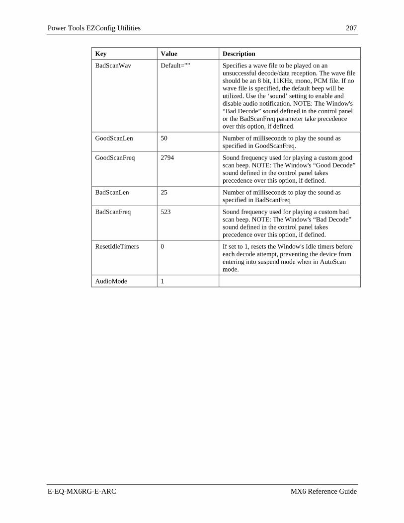
Power Tools EZConfig Utilities 207
E-EQ-MX6RG-E-ARC MX6 Reference Guide
Key Value Description
BadScanWav Default=”” Specifies a wave file to be played on an unsuccessful decode/data reception. The wave file should be an 8 bit, 11KHz, mono, PCM file. If no wave file is specified, the default beep will be utilized. Use the ‘sound’ setting to enable and disable audio notification. NOTE: The Window's “Bad Decode” sound defined in the control panel or the BadScanFreq parameter take precedence over this option, if defined.
GoodScanLen 50 Number of milliseconds to play the sound as specified in GoodScanFreq.
GoodScanFreq 2794 Sound frequency used for playing a custom good scan beep. NOTE: The Window's “Good Decode” sound defined in the control panel takes precedence over this option, if defined.
BadScanLen 25 Number of milliseconds to play the sound as specified in BadScanFreq
BadScanFreq 523 Sound frequency used for playing a custom bad scan beep. NOTE: The Window's “Bad Decode” sound defined in the control panel takes precedence over this option, if defined.
ResetIdleTimers 0 If set to 1, resets the Window's Idle timers before each decode attempt, preventing the device from entering into suspend mode when in AutoScan mode.
AudioMode 1

208 Power Tools EZConfig Utilities
MX6 Reference Guide E-EQ-MX6RG-E-ARC
Symbologies The Symbologies settings specify the settings for each of the symbologies supported by the MX6’s decoder.
See Chapter 6 “Scanner\Imager Parameter Setup” for explanations of barcode parameter settings.
The settings are in the form:
Symbology Name= Enable, Parm1, Parm2, Parm3, Parm4, Parm5, Parm6, Parm7, Parm8
Where:
• Enable (0=Disable or 1=Enable): Specifies if the symbology is enabled or disabled. Disable symbologies not used to improve performance.
• Parm1...8: Specify the settings for the symbology, as documented in the HHP Decode API. Unused parameters are ignored.
Example:
Code 39 = 1,0,0,0,0,0,2,48,0
1 = Enable Code 39
0 = Don't transmit start and stop characters
0 = Read codes with or without check character
0 = Do not transmit check character
0 = Full ASCII mode is disabled
0 = Append mode is disabled
2 = Minimum length is 2 characters
48 = Maximium length is 48 characters
0 = Ignored parameter for Code 39
Key (*Default Selected/Active) Demo File Value SCANCONFIG.INI Default Value
Aztec Code * 1,1,3750,0,0,0,0,0,0 1,1,3750
Aztec Mesas 0,0,0,0,0,0,0,0,0 0,0,0,0,0,0,0
Codabar * 1,0,0,0,4,60,0,0,0 1,0,0,0,2,60
Code 11 0,1,4,80,0,0,0,0,0 1,1,4,80
Code 128 / EAN 128 * 1,0,80,0,0,0,0,0,0 1,0,80
Code 39 * 1,0,0,0,0,0,0,48,0 1,0,0,0,0,0,2,48
Code 49 * 1,1,81,0,0,0,0,0,0 1,1,81
Code 93 * 1,0,80,0,0,0,0,0,0 1,1,81
EAN.UCC Composites 0,1,300,0,0,0,0,0,0 1,1,300

Power Tools EZConfig Utilities 209
E-EQ-MX6RG-E-ARC MX6 Reference Guide
Key (*Default Selected/Active) Demo File Value SCANCONFIG.INI Default Value
Data Matrix * 1,1,1500,0,0,0,0,0,0 1,1,1500
EAN-8 * 1,1,0,0,0,1,0,0,0 1,0,0,0,0,0
EAN-13 * 1,1,0,0,0,1,0,0,0 1,0,0,0,0,0
Interleaved 2 of 5 * 1,0,0,4,80,0,0,0,0 1,0,0,6,80
MaxiCode * 1,0,1,150,0,0,0,0,0 1,0,1,150
MicroPDF417 0,1,366,0,0,0,0,0,0 1,1,2750
OCR 0,2,dddddddd,,,,0 0,2,dddddddd,,,,0
PDF417 * 1,1,2750,0,0,0,0,0,0 1,1,2750
QR Code 0,1,3500,0,0,0,0,0,0 0,1,3500
PostNet 0,0,0,0,0,0,0,0,0 0,0
Reduced Space Symbology (RSS) * 1,4,74,0,0,0,0,0,0 1,1,80
UPC-A * 1,1,1,0,0,0,1,0,0 1,0,0,0,0,0,0
UPC-E0 * 1,1,1,0,0,0,0,1,0 1,0,0,0,0,0,0,1
UPC-E1 0,1,1,0,0,0,0,1,0 1,0,0,0,0,0,0,1
ISBT 0,0,0,0,0,0,0,0,0 1
British Post 0,0,0,0,0,0,0,0,0 0
Canadian Post 0,0,0,0,0,0,0,0,0 0
Australian Post 0,0,0,0,0,0,0,0,0 0
Straight 2 of 5 IATA 0,4,48,0,0,0,0,0,0 0,4,80
Codablock 0,1,2048,0,0,0,0,0,0 0,0,2048
Japanese Post 0,0,0,0,0,0,0,0,0 0
Planet Code 0,0,0,0,0,0,0,0,0 0,0
Dutch Post 0,0,0,0,0,0,0,0,0 0
MSI 0,4,48,0,0,0,0,0,0 0,4,48,0
TCIF Linked Code 39 (TLC39) 0,0,0,0,0,0,0,0,0 0

210 Power Tools EZConfig Utilities
MX6 Reference Guide E-EQ-MX6RG-E-ARC
Key (*Default Selected/Active) Demo File Value SCANCONFIG.INI Default Value
Trioptic Code 0,0,0,0,0,0,0,0,0 N/A
Code 32 0,0,0,0,0,0,0,0,0 N/A
Straight 2 of 5 Industrial 0,4,48,0,0,0,0,0,0 N/A
Matrix 2 of 5 0,4,80,0,0,0,0,0,0 N/A
Plessey 0,4,48,0,0,0,0,0,0 N/A
China Post 0,4,80,0,0,0,0,0,0 N/A
Korea Post 0,4,48,0,0,0,0,0,0 N/A
Telepen 0,1,60,0,0,0,0,0,0 N/A
Code 16K 0,1,160,0,0,0,0,0,0 N/A
PosiCode 0,4,48,2,0,0,0,0,0 N/A
Coupon Code 0,0,0,0,0,0,0,0,0 N/A

Power Tools EZConfig Utilities 211
E-EQ-MX6RG-E-ARC MX6 Reference Guide
Centering Centering parameters are valid only when there is an imager installed in the MX6.
The centering feature is used to allow the user to accurately scan a selected barcode among a group of barcodes that are located closely together. When centering is turned on, the imager will only decode barcodes that intersect the centering window defined by the user. The centering window must intersect the center of the barcode.
The default centering settings define a 60 pixel square area in the center of the imager's field of view.
Key Value Description
CenteringEnable 0
Default: 0 Enable and disables decode centering feature for the decoder. If CenteringEnable is 1, barcodes will only be decoded if they are within the centering window specified by CenteringTop, CenteringBottom, CenteringLeft and CenteringRight.
CenteringTop 215
Default: 230 Specifies the top coordinate of the centering window.
CenteringBottom 265
Default: 250 Specifies the bottom coordinate of the centering window.
CenteringLeft 295
Default: 310 Specifies the left coordinate of the centering window.
CenteringRight 345
Default: 330 Specifies the right coordinate of the centering window.
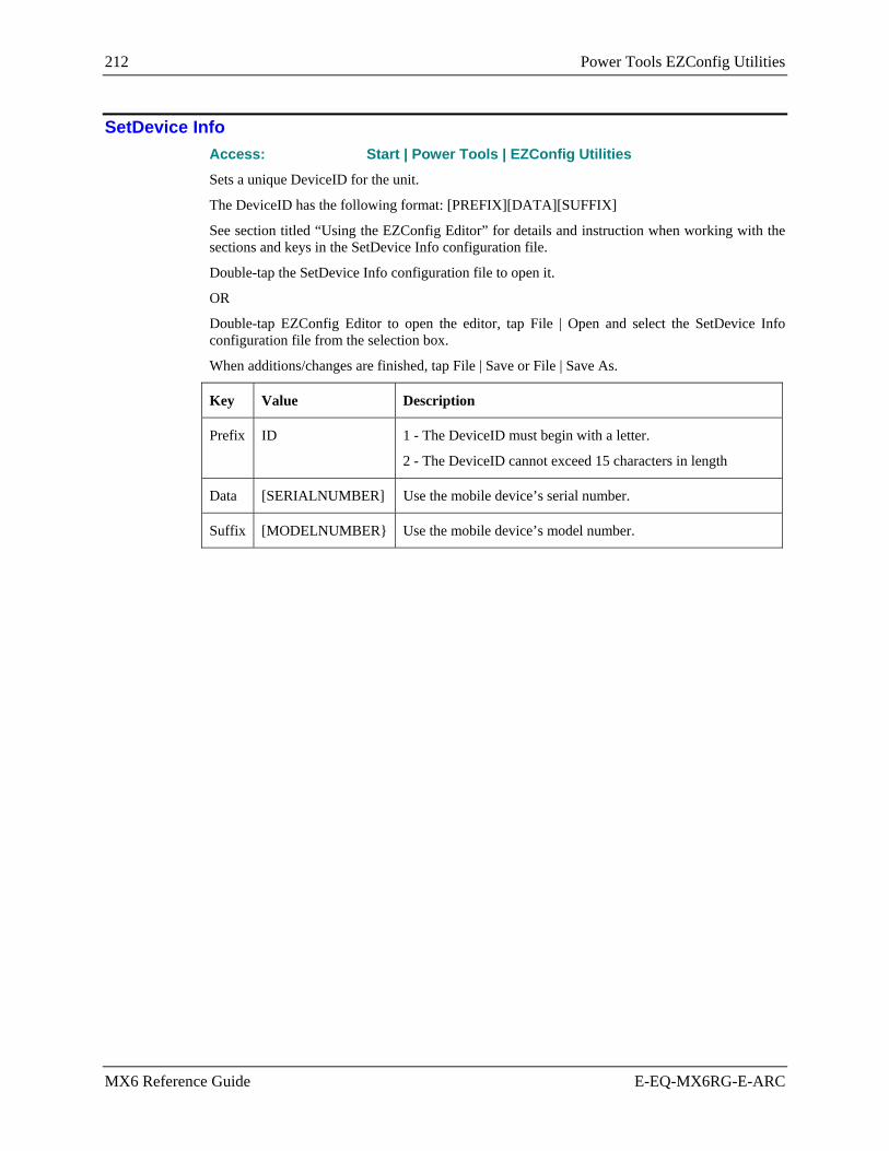
212 Power Tools EZConfig Utilities
MX6 Reference Guide E-EQ-MX6RG-E-ARC
SetDevice Info Access: Start | Power Tools | EZConfig Utilities Sets a unique DeviceID for the unit.
The DeviceID has the following format: [PREFIX][DATA][SUFFIX]
See section titled “Using the EZConfig Editor” for details and instruction when working with the sections and keys in the SetDevice Info configuration file.
Double-tap the SetDevice Info configuration file to open it.
OR
Double-tap EZConfig Editor to open the editor, tap File | Open and select the SetDevice Info configuration file from the selection box.
When additions/changes are finished, tap File | Save or File | Save As.
Key Value Description
Prefix ID 1 - The DeviceID must begin with a letter.
2 - The DeviceID cannot exceed 15 characters in length
Data [SERIALNUMBER] Use the mobile device’s serial number.
Suffix [MODELNUMBER} Use the mobile device’s model number.

Hat Encoding 213
E-EQ-MX6RG-E-ARC MX6 Reference Guide
Hat Encoding
See section titled “Scanner”, subsection titled “Advanced Tab”.
Desired ASCII
Hex Value
Hat Encoded Desired
ASCII Hex
Value Hat
Encoded NUL 00 ^@ ESA 87 ~^G SOH 01 ^A HTS 88 ~^H STX 02 ^B HTJ 89 ~^I ETX 03 ^C VTS 8A ~^J EOT 04 ^D PLD 8B ~^K ENQ 05 ^E
PLU 8C ~^L
ACK 06 ^F RI 8D ~^M BEL 07 ^G SS2 8E ~^N BS 08 ^H SS3 8F ~^O HT 09 ^I DCS 90 ~^P LF 0A ^J PU1 91 ~^Q VT 0B ^K PU2 92 ~^R FF 0C ^L STS 93 ~^S CR 0D ^M CCH 94 ~^T SO 0E ^N MW 95 ~^U SI 0F ^O SPA 96 ~^V
DLE 10 ^P EPA 97 ~^W DC1 (XON) 11 ^Q 98 ~^X
DC2 12 ^R 99 ~^Y DC3 (XOFF) 13 ^S 9A ~^Z
DC4 14 ^T CSI 9B ~^[ NAK 15 ^U ST 9C ~^\\ SYN 16 ^V OSC 9D ~^] ETB 17 ^W PM 9E ~^^ CAN 18 ^X APC 9F ~^_ (Underscore) EM 19 ^Y (no-break space) A0 ~ (Tilde and Space) SUB 1A ^Z ¡ A1 ~! ESC 1B ^[ ¢ A2 ~” FS 1C ^\\ £ A3 ~# GS 1D ^] ¤ A4 ~$ RS 1E ^^ ¥ A5 ~% US 1F ^_ (Underscore) ¦ A6 ~&
80 ~^@ § A7 ~’ 81 ~^A ¨ A8 ~( 82 ~^B © A9 ~) 83 ~^C ª AA ~*
IND 84 ~^D « AB ~+ NEL 85 ~^E ¬ AC ~, SSA 86 ~^F (soft hyphen) AD ~- (Dash)
Figure 4-84 Hat Encoded Characters Hex 00 through AD

214 Hat Encoding
MX6 Reference Guide E-EQ-MX6RG-E-ARC
Desired ASCII
Hex Value
Hat Encoded
Desired ASCII
Hex Value
Hat Encoded
® AE ~. (Period) × D7 ~W ¯ AF ~/ Ø D8 ~X ° B0 ~0 (Zero) Ù D9 ~Y ± B1 ~1 Ú DA ~Z ² B2 ~2 Û DB ~[ ³ B3 ~3 Ü DC ~\\ ´ B4 ~4 Ý DD ~] µ B5 ~5
Þ DE ~\^
¶ B6 ~6 ß DF ~_ (Underscore) · B7 ~7 à E0 ~` ¸ B8 ~8 á E1 ~a ¹ B9 ~9 â E2 ~b º BA ~: ã E3 ~c » BB ~; ä E4 ~d ¼ BC ~< å E5 ~e ½ BD ~= æ E6 ~f ¾ BE ~> ç E7 ~g ¿ BF ~? è E8 ~h À C0 ~@ é E9 ~i Á C1 ~A ê EA ~j  C2 ~B ë EB ~k à C3 ~C
ì EC ~l
Ä C4 ~D í ED ~m Å C5 ~E î EE ~n Æ C6 ~F ï EF ~o Ç C7 ~G ð F0 ~p È C8 ~H ñ F1 ~q É C9 ~I ò F2 ~r Ê CA ~J ó F3 ~s Ë CB ~K ô F4 ~t Ì CC ~L õ F5 ~u Í CD ~M ö F6 ~v Î CE ~N ÷ F7 ~w Ï CF ~O ø F8 ~x Ð D0 ~P ù F9 ~y Ñ D1 ~Q ú FA ~z Ò D2 ~R û FB ~{ Ó D3 ~S ü FC ~| Ô D4 ~T ý FD ~} Õ D5 ~U þ FE ~~ Ö D6 ~V ÿ FF ~^?
Figure 4-85 Hat Encoded Characters Hex AE through FF

Decimal - Hexadecimal Chart 215
E-EQ-MX6RG-E-ARC MX6 Reference Guide
Decimal - Hexadecimal Chart
0 0x00 40 0x28 80 0x50 120 0x78
1 0x01 41 0x29 81 0x51 121 0x79
2 0x02 42 0x2A 82 0x52 122 0x7A
3 0x03 43 0x2B 83 0x53 123 0x7B
4 0x04 44 0x2C 84 0x54 124 0x7C
5 0x05 45 0x2D 85 0x55 125 0x7D
6 0x06 46 0x2E 86 0x56 126 0x7E
7 0x07 47 0x2F 87 0x57 127 0x7F
8 0x08 48 0x30 88 0x58 128 0x80
9 0x09 49 0x31 89 0x59 129 0x81
10 0x0A 50 0x32 90 0x5A 130 0x82
11 0x0B 51 0x33 91 0x5B 131 0x83
12 0x0C 52 0x34 92 0x5C 132 0x84
13 0x0D 53 0x35 93 0x5D 133 0x85
14 0x0E 54 0x36 94 0x5E 134 0x86
15 0x0F 55 0x37 95 0x5F 135 0x87
16 0x10 56 0x38 96 0x60 136 0x88
17 0x11 57 0x39 97 0x61 137 0x89
18 0x12 58 0x3A 98 0x62 138 0x8A
19 0x13 59 0x3B 99 0x63 139 0x8B
20 0x14 60 0x3C 100 0x64 140 0x8C
21 0x15 61 0x3D 101 0x65 141 0x8D
22 0x16 62 0x3E 102 0x66 142 0x8E
23 0x17 63 0x3F 103 0x67 143 0x8F
24 0x18 64 0x40 104 0x68 144 0x90
25 0x19 65 0x41 105 0x69 145 0x91
26 0x1A 66 0x42 106 0x6A 146 0x92
27 0x1B 67 0x43 107 0x6B 147 0x93
28 0x1C 68 0x44 108 0x6C 148 0x94
29 0x1D 69 0x45 109 0x6D 149 0x95
30 0x1E 70 0x46 110 0x6E 150 0x96
31 0x1F 71 0x47 111 0x6F 151 0x97
32 0x20 72 0x48 112 0x70 152 0x98
33 0x21 73 0x49 113 0x71 153 0x99
34 0x22 74 0x4A 114 0x72 154 0x9A
35 0x23 75 0x4B 115 0x73 155 0x9B
36 0x24 76 0x4C 116 0x74 156 0x9C
37 0x25 77 0x4D 117 0x75 157 0x9D
38 0x26 78 0x4E 118 0x76 158 0x9E
39 0x27 79 0x4F 119 0x77 159 0x9F
Figure 4-86 Decimal - Hexadecimal Chart (0 to 159 Decimal)

216 Decimal - Hexadecimal Chart
MX6 Reference Guide E-EQ-MX6RG-E-ARC
160 0xA0 200 0xC8 240 0xF0
161 0xA1 201 0xC9 241 0xF1
162 0xA2 202 0xCA 242 0xF2
163 0xA3 203 0xCB 243 0xF3
164 0xA4 204 0xCC 244 0xF4
165 0xA5 205 0xCD 245 0xF5
166 0xA6 206 0xCE 246 0xF6
167 0xA7 207 0xCF 247 0xF7
168 0xA8 208 0xD0 248 0xF8
169 0xA9 209 0xD1 249 0xF9
170 0xAA 210 0xD2 250 0xFA
171 0xAB 211 0xD3 251 0xFB
172 0xAC 212 0xD4 252 0xFC
173 0xAD 213 0xD5 253 0xFD
174 0xAE 214 0xD6 254 0xFE
175 0xAF 215 0xD7 255 0xFF
176 0xB0 216 0xD8
177 0xB1 217 0xD9
178 0xB2 218 0xDA
179 0xB3 219 0xDB
180 0xB4 220 0xDC
181 0xB5 221 0xDD
182 0xB6 222 0xDE
183 0xB7 223 0xDF
184 0xB8 224 0xE0
185 0xB9 225 0xE1
186 0xBA 226 0xE2
187 0xBB 227 0xE3
188 0xBC 228 0xE4
189 0xBD 229 0xE5
190 0xBE 230 0xE6
191 0xBF 231 0xE7
192 0xC0 232 0xE8
193 0xC1 233 0xE9
194 0xC2 234 0xEA
195 0xC3 235 0xEB
196 0xC4 236 0xEC
197 0xC5 237 0xED
198 0xC6 238 0xEE
199 0xC7 239 0xEF
Figure 4-87 Decimal - Hexadecimal Chart (160 to 255 Decimal)

E-EQ-MX6RG-E-ARC MX6 Reference Guide
Chapter 5 AppLock
Introduction
LXE’s AppLock is designed to be run on LXE certified Windows CE based devices only. LXE loads the AppLock program as part of the LXE customer installation process.
Configuration parameters are specified by the AppLock Administrator for the mobile device end-user. AppLock is password protected by the Administrator.
End-user mode locks the end-user into the configured application or applications. The end user can still reboot the mobile device and respond to dialog boxes. The administrator-specified application is automatically launched and runs in full screen mode when the device boots up.
When the mobile device is reset to factory default values, for example after a cold reset, the Administrator may need to reconfigure the AppLock parameters.
Sections in this chapter that are not specifically Multi-Application or Single Application are used/changed in the same way by both versions.
Note: LXE has made the assumption, in this chapter, that the first user to power up a new mobile device is the system administrator.
Setup a New Device
LXE devices with the AppLock feature are shipped to boot in Administration mode with no default password, thus when the device is first booted, the user has full access to the device and no password prompt is displayed. After the administrator specifies an application to lock, a password is assigned and the device is rebooted or the hotkey is pressed, the device switches to end-user mode.
Briefly, the process to configure a new device is as follows:
1. Insert a fully charged battery and press the Power button.
2. Connect an external power source to the device (if required).
3. Adjust screen display, audio volume and other parameters if desired. Install accessories (e.g. handstrap, stylus).
4. Tap | Settings | System | Administration icon.
5. Assign an application on the Control (single application) or Application (dual application) tab screen.
6. Assign a password on the Security tab screen.
7. Select a view level on the Status tab screen, if desired.
8. Tap OK
9. Press the hotkey sequence to launch AppLock and lock the configured application(s).
10. The device is now in end-user mode.
Important: Before setting up multiple application parameters, make sure the targeted software application will allow two versions to run at the same time.

218 Setup a New Device
MX6 Reference Guide E-EQ-MX6RG-E-ARC
Multi-Application Version Access: Start | Settings | System | Administration icon A mobile device running the Multi-Application version of AppLock becomes a dedicated, dual application device. Only the applications or features specified in the AppLock configuration by the Administrator are available to the user. This version offers a user-mode taskbar icon allowing the user to switch between user applications.
See section titled Multi-Application Configuration for information and instruction.
Figure 5-1 Administrator Control Panels – Multi-Application
Single Application Version Access: Start | Settings | System | Administration icon
A mobile device running the Single Application version of AppLock becomes a dedicated, single application device. In other words, only the application or feature specified in the AppLock configuration by the Administrator is available to the user.
See section titled Single Application Configuration for information and instruction.
Figure 5-2 Administrator Control Panels – Single Application

Administration Mode 219
E-EQ-MX6RG-E-ARC MX6 Reference Guide
Administration Mode
Administration mode gives full access to the mobile device, hardware and software configuration options.
The administrator must enter a valid password (when a password has already been assigned) before access to Administration mode and configuration options are allowed. The administrator can configure the following options:
1. Create/change the keystroke sequence to activate administrator access.
2. Create/change the password for administrator access.
3. Assign the name of the application, or applications, to lock.
4. Select the command line of the application, or applications, to lock.
In addition to these configuration options, the administrator can view and manage the status logs of AppLock sessions.
Administrator default values for this device:
Administrator Hotkey Ctrl+Shift+A
Password none
Application path and name none
Application command line none
End User Mode
End-user mode locks the end-user into the configured application (or applications). The end user can still reboot and respond to dialog boxes. Each application is automatically launched, and runs in full screen mode when the device boots up.
The user cannot unintentionally or intentionally exit the application nor can the end user execute any other applications. Normal application exit or switching methods and all Microsoft defined Windows CE key combinations, such as close (X) icon, File Exit, File Close, Alt-F4, Alt-Tab, etc. are disabled. The Windows CE desktop icons, menu bars, task bar and system trays are not visible or accessible. Task Manager is not available.
If the end-user selects File/Exit or Close from the applications menu bar, the menu is cleared and nothing else happens; the application remains active. Nothing happens when the end-user taps on the Close icon on the application’s title bar and the application remains active.
Note: A few applications do not follow normal procedures when closing. AppLock cannot prevent this type of application from closing, but is notified that the application has closed. For these applications, AppLock immediately restarts the application which causes the screen to flicker. If this type of application is being locked, the administrator should close all other applications before switching to end user mode to minimize the screen flicker.
Windows accelerator keys such as Alt-F4 are disabled.

220 Passwords
MX6 Reference Guide E-EQ-MX6RG-E-ARC
Passwords
A password must be configured. If the password is not configured, a new device switches into Administration mode without prompting for a password. In addition to the hotkey press, a mode switch occurs if inaccurate information has been configured or if mandatory information is missing in the configuration.
There are several situations that display a password prompt after a password has been configured.
If the configured hotkey is pressed, the password prompt is displayed. In this case the user has 30 seconds to enter a password. If a valid password is not entered within 30 seconds, the password prompt is dismissed and the device returns to end-user mode.
All other situations that present the password prompt do not dismiss the prompt -- this is because the other situations result in invalid end-user operation.
These conditions include:
• If inaccurate configuration information is entered by the administrator, i.e. an application is specified that does not exist.
• If the application name, which is mandatory for end-user mode, is missing in the configuration.
• Invalid installation of AppLock (e.g. missing DLLs).
• Corrupted registry settings.
To summarize, if an error occurs that prevents AppLock from switching to user mode, the password will not timeout and AppLock will wait until the correct password is entered.
Troubleshooting
Can’t locate the password that has been set by the administrator? Enter this LXE back door key sequence:
Ctrl+L Ctrl+X Ctrl+E
or
Ctrl+5 Ctrl+9 Ctrl+3

Multi-Application Configuration 221
E-EQ-MX6RG-E-ARC MX6 Reference Guide
Multi-Application Configuration
The default Administrator Hotkey sequence is Ctrl+Shift+A.
Administrator mode allows access to all features on the device. When the hotkey is pressed to switch into Administrator mode, a password prompt is displayed (if a password has been configured). A password must be entered within 30 seconds (and within three tries) or the password prompt is removed and the device remains in end-user mode with the focus returned to the locked application. Without entry of a valid password, the switch into Administrator mode will not occur.
Access: Start | Settings | System | Administration icon
The password prompt is displayed if a password has been configured. When the valid password is entered, the Administration Control panel is displayed. When a valid password is not entered within 30 seconds, the user is returned to the System Control Panel.
If a password has not been configured, the Administrator Control panel is displayed.
Important: Before setting up multiple application parameters, make sure the targeted software application will allow two versions to run at the same time.
Application Panel
Figure 5-3 Application Panel – Multi-Application
Note: If your Application Panel does not look like the figure shown above, you may have the Single Application version.
Use the Application tab options to select the applications to launch when the device boots up in End User Mode.
Move the cursor to the Filename text box and either type the application path or tap the Browse button (the … button). The standard Windows CE Browse dialog is displayed. After selecting the application from the Browse dialog, tap OK.
Enter the Title to be associated with the application’s icon. The assumption is that multiple copies of the same application may need unique text for the icon in order to differentiate them in the application switcher panel.
Enter the command line parameters for the application in the Arguments text box.

222 Multi-Application Configuration
MX6 Reference Guide E-EQ-MX6RG-E-ARC
Enter the Order in which the application is to be loaded or presented to the end user. Applications are launched in lowest to highest number order.
Enable the Internet checkbox to use the End User Internet Explorer (EUIE.EXE) When the checkbox is enabled, the Internet Menu and Internet Status are available. See the section titled End User Internet Explorer for more details.
Select the Global Key key sequence the end user is to press when switching between applications. The Global Key default key sequence is Ctrl+Spc. The Global key is selected from a predefined list of Global hotkey combinations. The Global key is presented to the end-user as the Activation key.
Enter the number of seconds in Global Delay that both Applications must wait before starting to run upon reboot.
Tap the Clear button to clear all Application information that are currently displayed. The Global settings remain the same for both applications.
Use the left and right scroll buttons to move from application setup screen to application setup screen. The left and right buttons update the information on the screen with the previous or next configured application respectively.
If no application is specified when the Administrator Control applet is closed, the device reboots into Administrator mode. If a password has been set, but an application has not been specified, the user will be prompted for the password before entering administration mode. The password prompt remains on the display until a valid password is entered.
End User Internet Explorer (EUIE) AppLock supports applications that utilize Internet Explorer, such as .HTML pages and JAVA applications. The end user can run an application by entering the application name and path in Internet Explorer’s address bar.
To prevent the end user from executing an application using this method, the address bar and Options settings dialog are restricted in Internet Explorer. This is accomplished by creating an Internet Explorer that is used in end user mode: End-user Internet Explorer (EUIE.EXE). The EUIE executes the Internet Explorer application in full screen mode which removes the address bar and status bar. The Options Dialog is also removed so the end user cannot re-enable the address bar.
The administrator specifies the EUIE by checking the Internet checkbox in the Application tab of the Administrator applet. The internet application should then be entered in the Application text box.
When the Internet checkbox is enabled, the Menu and Status check boxes are available.
Enabling the Menu checkbox displays the EUIE menu which contains navigation functions like Back, Forward, Home, Refresh, etc., functions that are familiar to most Internet Explorer users. When the Menu checkbox is blank, the EUIE menu is not displayed and Navigation functions are unavailable.
When the Status checkbox is enabled, the status bar displayed by EUIE gives feedback to the end-user when they are navigating the Internet.
If the standard Internet Explorer that is shipped with the mobile device is desired, it should be treated like any other application. This means that IEXPLORER.EXE should be specified in the Application text box and the internet application should be entered in the command line. In this case, do not check the Internet checkbox.

Multi-Application Configuration 223
E-EQ-MX6RG-E-ARC MX6 Reference Guide
Security Panel
Figure 5-4 Security Panel – Multi-Application
Hotkey
Specify the hotkey sequence that triggers AppLock to switch between administrator and user modes and the password required to enter Administrator mode. The default hotkey sequence is Ctrl+Shift+A.
A 2nd key keypress is an invalid keypress for a hotkey sequence.
Move the cursor to the Hot Key text box. Enter the new hot key sequence by first pressing the Shift state key followed by a normal key. The hotkey selected must be a key sequence that the application being locked does not use. The hotkey sequence is intercepted by AppLock and is not passed to the application.
Input from the keyboard or Input Panel is accepted with the restriction that the normal key must be pressed from the keyboard when switching modes. The hotkey sequence is displayed in the Hot key text box with “Shift”, “Alt”, and “Ctrl” text strings representing the shift state keys. The normal keyboard key completes the hotkey sequence. The hotkey must be entered via the keypad. Some hotkeys cannot be entered via the Input Panel. Also, hotkeys entered via the SIP are not guaranteed to work properly when switching operational modes.
For example, if the ‘Ctrl’ key is pressed followed by ‘A’, “Ctrl+A” is entered in the text box. If another key is pressed after a normal key press, the hotkey sequence is cleared and a new hotkey sequence is started.
A normal key is required for the hotkey sequence and is unlike pressing the normal key during a mode switch; this key can be entered from the SIP when configuring the key. However, when the hotkey is pressed to switch modes, the normal key must be entered from the keypad; it cannot be entered from the SIP.

224 Multi-Application Configuration
MX6 Reference Guide E-EQ-MX6RG-E-ARC
Password Move the cursor to the Password text box. The passwords entered in the Password and Confirm Password fields must match. Passwords are case sensitive.
When the user exits the Administrator Control panel, the two passwords are compared to verify that they match. If they do not match, a dialog box is displayed notifying the user of the error. After the user closes the dialog box, the Security Panel is displayed and the password can then be entered and confirmed again. If the passwords match, the password is encrypted and saved.
See Also: Passwords and Troubleshooting Multi-Application AppLock

Multi-Application Configuration 225
E-EQ-MX6RG-E-ARC MX6 Reference Guide
Status Panel Use the Status panel to view the log of previous AppLock operations and to configure which messages are to be recorded during AppLock operation.
Status information is stored in a specific location on the storage device and in a specific log file specified by the Administrator. For this reason, the administrator can configure the type of status information that is logged, as well as clear the status information.
Figure 5-5 Status Panel – Multi-Application
Move the cursor to the Filename text box and either type the log file path or tap the Browse button (the … button). The standard Windows CE Browse dialog is displayed. After selecting the log file from the Browse dialog, tap OK.
Note: If your Status Panel does not look like the figure shown above, you may have the Single Application version.
View
Error Error status messages are logged when an error occurs and is intended to be used by the administrator to determine why the specified application cannot be locked.
Process Processing status shows the flow control of AppLock components and is mainly intended for LXE Customer Service when helping users troubleshoot problems with their AppLock program.
Extended Extended status provides more detailed information than that logged by Process Logging.
All All messages are displayed.
Tap the Refresh button after changing from one view level to another. The filtered records are displayed, all others are not displayed.

226 Multi-Application Configuration
MX6 Reference Guide E-EQ-MX6RG-E-ARC
Log
Note: If a level higher than Error is selected, the status should be cleared frequently by the administrator.
In addition to the three view levels the administrator can select that all status information be logged or turn off all status information logging completely. The system default is ‘None’; however to reduce registry use, the administrator may want to select ‘None’ after verifying the configuration. Tap the Clear button to clear the status information from the registry.
• None • Error • Processing • Extended • All
Save As
When the 'Save As'… button is selected, a standard 'Save As' dialog screen is displayed. Specify the path and filename. If the filename exists, the user is prompted whether the file should be overwritten. If the file does not exist, it is created.
See Also: Error Messages

Multi-Application Configuration 227
E-EQ-MX6RG-E-ARC MX6 Reference Guide
End-User Switching Technique
Figure 5-6 End-User Multi-Application Touch Panel
Using a Stylus Tap When the mobile device enters end-user mode, a taskbar icon is available to the user so they can switch between the locked applications. The touch screen must be enabled on the mobile device before the taskbar icon can be used. The taskbar is always visible on top of the application in focus.
When the taskbar icon is tapped, a menu is displayed showing the applications available to the user. The user then taps the application name in the popup menu and the selected application is brought to the foreground. The previous application continues to run in the background. Stylus taps affect the application in focus only.
The appearance of the taskbar is different on various mobile device platforms and may differ from the example shown above. This example is shown only to aid in describing how the user can switch between applications using a stylus. If RFTerm and Microsoft Word were the two applications locked, a switching icon showing both applications is displayed on the screen.
Using a Hotkey Sequence One hotkey is defined for the end-user to key in when switching between locked applications. This is known as the Activation key. The Activation key is assigned by the Administrator using the Global Key parameter. When the hotkey or hotkey sequence is pressed on the keypad, the next application in the AppLock configuration is moved to the foreground and the previous application moves to the background. The previous application continues to run in the background but end-user key presses affect the application in focus only.

228 Multi-Application Configuration
MX6 Reference Guide E-EQ-MX6RG-E-ARC
Troubleshooting Multi-Application AppLock
The mobile device won’t switch from Administration mode to end-user mode.
• If the configuration is valid for one application but not the other, the switch to end-user mode fails. AppLock stays in Administration mode and is stopped until the Administrator password is entered.
• If two copies of the same application are configured, but the application only allows one copy to run at a time, for example Microsoft Pocket Word, the switch to end-user fails. AppLock stays in Administration mode and is stopped until the Administrator password is entered.
The hotkey sequence needed is not allowed. What does this mean?
When the Administrator is selecting a hotkey sequence to use when switching user modes, they are not allowed to enter key combinations that are reserved by installed software applications. LXE has validated RFTerm key combinations ONLY.
When RFTerm is installed on the mobile device and an RFTerm restricted key sequence is specified as a hotkey sequence by the Administrator, the following error message is displayed in a message box:
Selected hotkey is not allowed. Please reenter.
When RFTerm is not installed on the mobile device, the RFTerm keys are not restricted from use.

Single Application Configuration 229
E-EQ-MX6RG-E-ARC MX6 Reference Guide
Single Application Configuration
The default Administrator Hotkey sequence is Ctrl+Shift+A.
Administrator mode allows access to all features on the device. When the hotkey is pressed to switch into Administrator mode, a password prompt is displayed (if a password has been configured). A password must be entered within 30 seconds (and within three tries) or the password prompt is removed and the device remains in end-user mode with the focus returned to the locked application. Without entry of a valid password, the switch into Administrator mode will not occur.
Access: Start | Settings | System | Administration icon
The password prompt is displayed if a password has been configured. When the valid password is entered, the Administration Control panel is displayed. When a valid password is not entered within 30 seconds, the user is returned to the System Control Panel.
If a password has not been configured, the Administrator Control panel is displayed.
Control Panel
Figure 5-7 Control Panel
Note: If your Administrator Control Panel does not look like the figure shown above, you may have the Multi-Application version.
Use the Control tab options to select the application to launch when the device boots up.
Move the cursor to the Application text box and either type the application path or tap the Browse button (the … button). The standard Windows CE Browse dialog is displayed. After selecting the application from the Browse dialog, tap OK.
Enter the command line parameters for the application in the Command Line text box.
Enter the number of seconds the selected Application must wait before starting to run upon reboot.
If no application is specified when the Administrator Control panel is closed, the device reboots into Administrator mode. If a password has been set, but the application has not been specified, the user will be prompted for the password before entering administration mode. The password prompt remains on the display until a valid password is entered.

230 Single Application Configuration
MX6 Reference Guide E-EQ-MX6RG-E-ARC
End User Internet Explorer
AppLock supports applications that utilize Internet Explorer, such as .HTML pages and JAVA applications. The end user can run an application by entering the application name and path in Internet Explorer’s address bar.
To prevent the end user from executing an application using this method, the address bar and Options settings dialog are restricted in Internet Explorer. This is accomplished by creating an Internet Explorer that is used in end user mode, End-user Internet Explorer (EUIE). The EUIE executes the Internet Explorer application in full screen mode which removes the address bar and status bar. The Options Dialog is also removed so the end user cannot re-enable the address bar.
The administrator specifies the EUIE by simply checking the “Internet” checkbox in the Control tab of the Administrator applet. The internet application should then be entered in the “Application” text box. If the standard Internet Explorer that is shipped with the device is desired, it should be treated like any other application. This means that IEXPLORER.EXE should be specified in the Application text box and the internet application should be entered in the command line. In this case, do not check the Internet checkbox.
Security Panel
Figure 5-8 Security Panel
Hotkey
Specify the hotkey sequence that triggers AppLock to switch between administrator and user modes and the password required to enter Administrator mode. The default hotkey sequence is Ctrl+Shift+A.
A 2nd key keypress is an invalid keypress for a hotkey sequence.
Move the cursor to the Hot Key text box. Enter the new hot key sequence by first pressing the Shift state key followed by a normal key. The hotkey selected must be a key sequence that the application being locked does not use. The hotkey sequence is intercepted by AppLock and is not passed to the application.
Input from the keyboard or Input Panel is accepted with the restriction that the normal key must be pressed from the keyboard when switching modes. The hotkey sequence is displayed in the Hot key text box with “Shift”, “Alt”, and “Ctrl” text strings representing the shift state keys. The normal keyboard key completes the hotkey sequence. The hotkey must be entered via the keypad.

Single Application Configuration 231
E-EQ-MX6RG-E-ARC MX6 Reference Guide
Some hotkeys cannot be entered via the Input Panel. Also, hotkeys entered via the SIP are not guaranteed to work properly when switching operational modes.
For example, if the ‘Ctrl’ key is pressed followed by ‘A’, “Ctrl+A” is entered in the text box. If another key is pressed after a normal key press, the hotkey sequence is cleared and a new hotkey sequence is started.
A normal key is required for the hotkey sequence and is unlike pressing the normal key during a mode switch; this key can be entered from the SIP when configuring the key. However, when the hotkey is pressed to switch modes, the normal key must be entered from the keypad; it cannot be entered from the SIP.
Password
Move the cursor to the Password text box. The passwords entered in the Password and Confirm Password fields must match. Passwords are case sensitive.
When the user exits the Administrator Control panel, the two passwords are compared to verify that they match. If they do not match, a dialog box is displayed notifying the user of the error. After the user closes the dialog box, the Security Panel is displayed and the password can then be entered and confirmed again. If the passwords match, the password is encrypted and saved.
See Also: Passwords
Status Panel
Figure 5-9 Status Panel
Note: If your Status Panel does not look like the figure shown above, you may have the Multi-Application version.
Use the Status panel to view the log of previous AppLock operation and to configure which messages are to be recorded during AppLock operation.
As the status information is stored in the registry and accumulates during AppLock configuration and operation, it is very important that the administrator periodically clear the status information to reduce the amount of registry space used. For this reason, the administrator can configure the type of status information that is logged, as well as clear the status information.

232 Single Application Configuration
MX6 Reference Guide E-EQ-MX6RG-E-ARC
View
Error Error status messages are logged when an error occurs and is intended to be used by the administrator to determine why the specified application cannot be locked.
Process Processing status shows the flow control of AppLock components and is mainly intended for LXE Customer Service when helping users troubleshoot problems with their AppLock program.
Extended Extended status provides more detailed information than that logged by Process Logging.
All All messages are displayed.
Tap the Refresh button after changing from one view level to another. The filtered records are displayed, all others are not displayed.
Levels
Note: If a level higher than Error is selected, the status should be cleared frequently by the administrator.
In addition to the three view levels the administrator can select that all status information be logged or turn off all status information logging completely. The system default is ‘None’; however to reduce registry use, the administrator may want to select ‘None’ after verifying the configuration. Tap the Clear button to clear the status information from the registry.
• None • Error • Processing • Extended • All
Save As
When the 'Save As'… button is selected, a standard 'Save As' dialog screen is displayed. Specify the path and filename. If the filename exists, the user is prompted whether the file should be overwritten. If the file does not exist, it is created.
See Also: Error Messages

AppLock Error Messages 233
E-EQ-MX6RG-E-ARC MX6 Reference Guide
AppLock Error Messages
Any messages whose first word is an ‘ing’ word is output prior to the action described in the message. For example, “Switching to admin-hotkey press” is logged after the administrator has pressed the hotkey but prior to starting the switch process.
For all operations that can result in an error, an Error level message is displayed when a failure occurs. These messages contain the word “failure”. These messages have a partner Extended level message that is logged which contains the word “OK” if the action completed successfully rather than with an error.
For processing level messages, “Enter…” is logged at the beginning of the function specified in the message and “Exit…” is logged at the end (just before the return) of the function specified in the message.
Message Explanation and/or corrective action Level
Error reading hotkey The hotkey is read but not required by AppLock. LOG_EX
Error reading hotkey; using default A hotkey is required. If there is a failure reading the hotkey, the internal factory default is used.
LOG_ERROR
App Command Line= <Command line>
Command line of the application being locked LOG_PROCESSING
App= <Application name> Name of the application being locked LOG_PROCESSING
dwProcessID= <#> Device ID of the application being locked LOG_EX
Encrypt exported key len <#> Size of encrypt export key LOG_EX
Encrypt password length= <#> The length of the encrypted password. LOG_EX
Encrypted data len <#> Length of the encrypted password LOG_EX
hProcess= <#> Handle of the application being locked LOG_EX
Key pressed = <#> A key has been pressed and trapped by the hotkey processing.
LOG_EX
***************** The status information is being saved to a file and the file has been opened successfully.
LOG_EX
Address of keyboard hook procedure failure
AppLock found the kbdhook.dll, but was unable to get the address of the initialization procedure. For some reason the dll is corrupted. Look in the \Windows directory for kbdhook.dll. If it exists, delete it. Also delete applock.exe from the \Windows directory and reboot the unit. Deleting applock.exe triggers the AppLock system to reload.
LOG_ERROR
Address of keyboard hook procedure OK
AppLock successfully retrieved the address of the keyboard filter initialization procedure.
LOG_EX
Alt pressed The Alt key has been pressed and trapped by the HotKey processing.
LOG_EX
Alt Processing the hotkey and backdoor entry LOG_EX
Application handle search failure The application being locked did not complete initialization.
LOG_ERROR
Application handle search OK The application initialized itself successfully LOG_ERROR
Application load failure The application could not be launched by AppLock; the application could not be found or is corrupted.
LOG_ERROR

234 AppLock Error Messages
MX6 Reference Guide E-EQ-MX6RG-E-ARC
Message Explanation and/or corrective action Level
Backdoor message received The backdoor keys have been pressed. The backdoor hotkeys provide a method for customer service to get a user back into their system without editing the registry or reloading the device.
LOG_PROCESSING
Cannot find kbdhook.dll The load of the keyboard filter failed. This occurs when the dll is missing or is corrupted. Look in the \Windows directory for kbdhook.dll. If it exists, delete it. Also delete applock.exe from the \Windows directory and reboot the unit. Deleting applock.exe triggers the AppLock system to reload.
LOG_ERROR
Converted Pwd Converted password from wide to mbs. LOG_EX
Could not create event EVT_HOTKEYCHG
The keyboard filter uses this event at the Administrator Control panel. The event could not be created.
LOG_ERROR
Could not hook keyboard If the keyboard cannot be controlled, AppLock cannot process the hotkey. This failure prevents a mode switch into user mode.
LOG_ERROR
Could not start thread HotKeyMon The keyboard filter must watch for hot key changes. The watch process could not be initiated.
LOG_ERROR
Ctrl after L or X Processing the backdoor entry. LOG_EX
Ctrl pressed The Ctrl key has been pressed and trapped by the HotKey processing.
LOG_EX
Ctrl Processing the hotkey and backdoor entry. LOG_EX
Decrypt acquire context failure Unable to decrypt password. LOG_ERROR
Decrypt acquired context OK Decryption process ok. LOG_EX
Decrypt create hash failure Unable to decrypt password. LOG_ERROR
Decrypt created hash OK Decryption process ok. LOG_EX
Decrypt failure Unable to decrypt password. LOG_ERROR
Decrypt import key failure Unable to decrypt password. LOG_ERROR
Decrypt imported key OK Decryption process ok. LOG_EX
Encrypt acquire context failure Unable to encrypt password. LOG_ERROR
Encrypt acquire encrypt context failure
Unable to encrypt password. LOG_ERROR
Encrypt acquired encrypt context OK
Encrypt password process successful. LOG_EX
Encrypt create hash failure Unable to encrypt password. LOG_ERROR
Encrypt create key failure Unable to encrypt password. LOG_ERROR
Encrypt created encrypt hash OK Encrypt password process successful. LOG_EX
Encrypt export key failure Unable to encrypt password. LOG_ERROR
Encrypt export key length failure Unable to encrypt password. LOG_ERROR
Encrypt exported key OK Encrypt password process successful. LOG_EX
Encrypt failure The password encryption failed. LOG_ERROR
Encrypt gen key failure Unable to encrypt password. LOG_ERROR
Encrypt generate key failure Unable to encrypt password. LOG_ERROR

AppLock Error Messages 235
E-EQ-MX6RG-E-ARC MX6 Reference Guide
Message Explanation and/or corrective action Level
Encrypt get user key failure Unable to encrypt password. LOG_ERROR
Encrypt get user key ok Encrypt password process successful. LOG_EX
Encrypt hash data failure Unable to encrypt password. LOG_ERROR
Encrypt hash data from pwd OK Encrypt password process successful. LOG_EX
Encrypt length failure Unable to encrypt password. LOG_ERROR
Encrypt out of memory for key Unable to encrypt password. LOG_ERROR
Encrypted data OK The password has been successfully encrypted. LOG_EX
Enter AppLockEnumWindows In order for AppLock to control the application being locked so it can prevent the application from exiting, AppLock launches the application and has to wait until it has created and initialized its main window. This message is logged when the function that waits for the application initialization is entered.
LOG_EX
Enter DecryptPwd Entering the password decryption process. LOG_PROCESSING
Enter EncryptPwd Entering the password encryption processing. LOG_PROCESSING
Enter FullScreenMode Entering the function that switches the screen mode. In full screen mode, the taskbar is hidden and disabled.
LOG_PROCESSING
Enter GetAppInfo Processing is at the beginning of the function that retrieves the application information from the registry.
LOG_PROCESSING
Enter password dialog Entering the password dialog processing. LOG_PROCESSING
Enter password timeout Entering the password timeout processing. LOG_PROCESSING
Enter restart app timer Some application shut down before AppLock can stop it. In these cases, AppLock gets notification of the exit. When the notification is received, AppLock starts a timer to restart the application. This message logs that the timer has expired and the processing is at the beginning of the timer function.
LOG_PROCESSING
Enter TaskbarScreenMode Entering the function that switches the screen to non-full screen mode and enable the taskbar.
LOG_PROCESSING
Enter ToAdmin Entering the function that handles a mode switch into admin mode.
LOG_PROCESSING
Enter ToUser Entering the function that handles the mode switch to user mode
LOG_PROCESSING
Enter verify password Entering the password verification processing. LOG_PROCESSING
Exit AppLockEnumWindows-Found
There are two exit paths from the enumeration function. This message denotes the enumeration function found the application.
LOG_PROCESSING
Exit AppLockEnumWindows-Not found
There are two exit paths from the enumeration function. This message denotes the enumeration function did not find the application.
LOG_PROCESSING
Exit DecryptPwd Exiting password decryption processing. LOG_PROCESSING
Exit EncryptPwd Exiting password encryption processing. LOG_PROCESSING
Exit FullScreenMode Exiting the function that switches the screen to full screen.
LOG_PROCESSING
Exit GetAppInfo Processing is at the end of the function that retrieved the LOG_PROCESSING

236 AppLock Error Messages
MX6 Reference Guide E-EQ-MX6RG-E-ARC
Message Explanation and/or corrective action Level application information from the registry.
Exit password dialog Exiting password prompt processing. LOG_PROCESSING
Exit password dialog-cancel Exiting password prompt w/cancel. LOG_PROCESSING
Exit password dialog-OK Exiting password prompt successfully. LOG_PROCESSING
Exit password timeout Exiting password timeout processing. LOG_PROCESSING
Exit restart app timer Processing is at the end of the timer function LOG_PROCESSING
Exit TaskbarScreenMode Exiting the function that switches the screen mode back to normal operation for the administrator.
LOG_PROCESSING
Exit ToAdmin Exiting the function that handles the mode switch into admin mode.
LOG_PROCESSING
Exit ToUser Exiting the user mode switch function. LOG_PROCESSING
Exit ToUser-Registry read failure The AppName value does not exist in the registry so user mode cannot be entered.
LOG_PROCESSING
Exit verify password-no pwd set Exiting password verification. LOG_PROCESSING
Exit verify password-response from dialog
Exiting password verification. LOG_PROCESSING
Found taskbar The handle to the taskbar has been found so that AppLock can disable it in user mode.
LOG_PROCESSING
Getting address of keyboard hook init procedure
AppLock is retrieving the address of the keyboard hook. LOG_PROCESSING
Getting configuration from registry The AppLock configuration is being read from the registry. This occurs at initialization and also at entry into user mode. The registry must be re-read at entry into user mode in case the administration changed the settings of the application being controlled.
LOG_PROCESSING
Getting encrypt pwd length The length of the encrypted password is being calculated.
LOG_EX
Hook wndproc failure AppLock is unable to lock the application. This could happen if the application being locked encountered an error after performing its initialization and shut itself down prior to being locked by AppLock.
LOG_ERROR
Hook wndproc of open app failure The application is open, but AppLock cannot lock it. LOG_ERROR
Hot key event creation failure The Admin applet is unable to create the hotkey notification.
LOG_ERROR
Hot key pressed Processing the hotkey and backdoor entry LOG_EX
Hot key pressed Processing the hotkey and backdoor entry LOG_EX
Hot key set event failure When the administrator changes the hotkey configuration the hotkey controller must be notified. This notification failed.
LOG_ERROR
Hotkey press message received The user just pressed the configured hotkey. LOG_PROCESSING
In app hook:WM_SIZE In addition to preventing the locked application from exiting, AppLock must also prevent the application from enabling the taskbar and resizing the application’s window. This message traps a change in the window size and corrects it.
LOG_EX

AppLock Error Messages 237
E-EQ-MX6RG-E-ARC MX6 Reference Guide
Message Explanation and/or corrective action Level
In app hook:WM_WINDOWPOSCHANGED
In addition to preventing the locked application from exiting, AppLock must also prevent the application from enabling the taskbar and resizing the application’s window. This message traps a change in the window position and corrects it.
LOG_EX
Initializing keyboard hook procedure
AppLock is calling the keyboard hook initialization. LOG_PROCESSING
Keyboard hook initialization failure The keyboard filter initialization failed. LOG_ERROR
Keyboard hook loaded OK The keyboard hook dll exists and loaded successfully. LOG_EX
L after Ctrl Processing the backdoor entry. LOG_EX
Loading keyboard hook When AppLock first loads, it loads a dll that contains the keyboard hook processing. This message is logged prior to the load attempt.
LOG_PROCESSING
Open failure The status information is being saved to a file and the file open has failed. This could occur if the file is write protected. If the file does not exist, it is created.
LOG_ERROR
Open registry failure If the Administration registry key does not exist, the switch to user mode fails because the AppName value in the Administration key is not available.
LOG_ERROR
Opened status file The status information is being saved to a file and the file has been opened successfully.
LOG_EX
Out of memory for encrypted pwd Not enough memory to encrypt the password. LOG_ERROR
pRealTaskbarWndProc already set The taskbar control has already been installed. LOG_EX
Pwd cancelled or invalid-remain in user mode
The password prompt was cancelled by the user or the maximum number of failed attempts to enter a password was exceeded.
LOG_EX
Read registry error-hot key The hotkey registry entry is missing or empty. This is not considered an error. The keyboard hook uses an embedded default if the value is not set in the registry.
LOG_ERROR
Read registry failure-app name AppName registry value does not exist or is empty. This constitutes a failure for switching into user mode.
LOG_ERROR
Read registry failure-Cmd Line AppCommandLine registry entry is missing or empty. This is not considered an error since command line information is not necessary to launch and lock the application.
LOG_ERROR
Read registry failure-Internet The Internet registry entry is missing or empty. This is not considered an error since the Internet value is not necessary to launch and lock the application.
LOG_ERROR
Registering Backdoor MSG The AppLock system communicates with the keyboard hook via a user defined message. Both AppLock.exe and Kbdhook.dll register the message at initialization.
LOG_PROCESSING
Registering Hotkey MSG The AppLock system communicates with the keyboard hook via a user defined message. Both Applock.exe and Kbdhook.dll register the message at initialization.
LOG_PROCESSING
Registry read failure at reenter user mode
The registry has to be read when entering user mode is the AppName is missing. This user mode entry is attempted at boot and after a hotkey switch when the administrator has closed the application being locked or
LOG_ERROR

238 AppLock Error Messages
MX6 Reference Guide E-EQ-MX6RG-E-ARC
Message Explanation and/or corrective action Level has changed the application name or command line.
Registry read failure at reenter user mode
The registry has to be read when switching into user mode. This is because the administrator can change the settings during administration mode. The read of the registry failed which means the Administration key was not found or the AppName value was missing or empty.
LOG_ERROR
Registry read failure The registry read failed. The registry information read when this message is logged is the application information. It the Administration key cannot be opened or if the AppName value is missing or empty, this error is logged. The other application information is not required. If the AppName value is not available, AppLock cannot switch into user mode.
LOG_ERROR
Reset system work area failure The system work area is adjusted when in user mode to cover the taskbar area. The system work area has to be adjusted to exclude the taskbar area in administration mode. AppLock was unable to adjust this area.
LOG_ERROR
Shift pressed The Shift key has been pressed and trapped by the HotKey processing.
LOG_EX
Shift Processing the hotkey and backdoor entry LOG_EX
Show taskbar The taskbar is now being made visible and enabled. LOG_PROCESSING
Switching to admin-backdoor The system is currently in user mode and is now switching to admin mode. The switch occurred because of the backdoor key presses were entered by the administrator.
LOG_PROCESSING
Switching to admin-hotkey press The system is currently in user mode and is now switching to admin mode. The switch occurred because of a hotkey press by the administrator.
LOG_PROCESSING
Switching to admin-kbdhook.dll not found
The keyboard hook load failed, so AppLock switches to admin mode. If a password is specified, the password prompt is displayed and remains until a valid password is entered.
LOG_PROCESSING
Switching to admin-keyboard hook initialization failure
If the keyboard hook initialization fails, AppLock switches to admin mode. If a password is specified, the password prompt is displayed and remains until a valid password is entered.
LOG_PROCESSING
Switching to admin-registry read failure
See the explanation of the “Registry read failure” above. AppLock is switching into Admin mode. If a password has been configured, the prompt will be displayed and will not be dismissed until a valid password is entered.
LOG_PROCESSING
Switching to TaskbarScreenMode In administration mode, the taskbar is visible and enabled.
LOG_EX
Switching to user mode The registry was successfully read and AppLock is starting the process to switch to user mode.
LOG_PROCESSING
Switching to user-hotkey press The system is currently in admin mode and is now switching to user mode. The switch occurred because of a hotkey press by the administrator.
LOG_PROCESSING
Taskbar hook failure AppLock is unable to control the taskbar to prevent the locked application from re-enabling it.
LOG_ERROR
Taskbar hook OK AppLock successfully installed control of the taskbar. LOG_EX

AppLock Error Messages 239
E-EQ-MX6RG-E-ARC MX6 Reference Guide
Message Explanation and/or corrective action Level
Timeout looking for app window After the application is launched, AppLock must wait until the application has initialized itself before proceeding. The application did not start successfully and AppLock has timed out.
LOG_ERROR
ToUser after admin, not at boot The user mode switch is attempted when the device boots and after the administrator presses the hotkey. The mode switch is being attempted after a hotkey press.
LOG_EX
ToUser after admin-app still open The switch to user mode is being made via a hotkey press and the administrator has left the application open and has not made any changes in the configuration.
LOG_EX
ToUser after admin-no app or cmd line change
If user mode is being entered via a hotkey press, the administrator may have left the configured application open. If so, AppLock does not launch the application again unless a new application or command line has been specified; otherwise, it just locks it.
LOG_EX
Unable to move desktop The desktop is moved when switching into user mode. This prevents them from being visible if the application is exited and restarted by the timer. This error does not affect the screen mode switch; processing continues.
LOG_ERROR
Unable to move taskbar The taskbar is moved when switching into user mode. This prevents them from being visible if the application is exited and restarted by the timer. This error does not affect the screen mode switch; processing continues.
LOG_ERROR
Unhook taskbar wndproc failure AppLock could not remove its control of the taskbar. This error does not affect AppLock processing
LOG_ERROR
Unhook wndproc failure AppLock could not remove the hook that allows monitoring of the application.
LOG_ERROR
Unhooking taskbar In administration mode, the taskbar should return to normal operation, so AppLock’s control of the taskbar should be removed.
LOG_EX
Unhooking wndproc When the administrator leaves user mode, the device is fully operational; therefore, AppLock must stop monitoring the locked application.
LOG_EX
WM_SIZE adjusted This message denotes that AppLock has readjusted the window size.
LOG_EX
X after Ctrl+L Processing the backdoor entry. LOG_EX
Ret from password <#> Return value from password dialog. LOG_EX
Decrypt data len <#> Length of decrypted password. LOG_EX
Window handle to enumwindows=%x
The window handle that is passed to the enumeration function. This message can be used by engineering with other development tools to trouble shoot application lock failures.
LOG_EX
WM_WINDOWPOSCHG adjusted=%x
Output the window size after it has been adjusted by AppLock
LOG_EX

240 AppLock Registry Settings
MX6 Reference Guide E-EQ-MX6RG-E-ARC
AppLock Registry Settings
This system application runs at startup via the “launch” feature of LXE Windows based devices. When the launch feature is installed on the device, the following registry settings are created. The launch feature registry settings are embedded in the mobile device OS image: HKEY_LOCAL_MACHINE\\Software\\LXE\\Persist\\Filename=AppLock.exe HKEY_LOCAL_MACHINE\\Software\\LXE\\Persist\\Installed= HKEY_LOCAL_MACHINE\\Software\\LXE\\Persist\\FileCheck=
AppLock registry settings identify the application that is going to be locked and any parameters that are needed by the application. These registry settings are as follows: HKEY_LOCAL_MACHINE\\Software\\LXE\\Administration\\AppName HKEY_LOCAL_MACHINE\\Software\\LXE\\AppCommandLine=
In addition to the registry settings needed to specify the application, additional registry settings are needed to store the configuration options for AppLock. These options include, among others, the administrator’s password and hotkey. HKEY_LOCAL_MACHINE\\Software\\LXE\\AppLock\\Administration\\HotKey= HKEY_LOCAL_MACHINE\\Software\\LXE\\AppLock\\Administration\\EP=

E-EQ-MX6RG-E-ARC MX6 Reference Guide
Chapter 6 Scanner/Imager Parameter Setup
Introduction
See Also: Section titled “Sample SCANCONFIG.INI File”.
• Note that settings indicated by a * have an effect only on MX6 units equipped with an imager. These settings have no effect on laser scanner-equipped units.
• Symbologies indicated by a * can only be decoded by imager-equipped units. Altering their settings has no effect on units equipped with a laser scanner.
After configuration is complete, save the modified scanner configuration file and perform a soft reset (press and hold SFT + CTRL) in order for the new settings to take effect.
See Also: “Scandemo” in Power Tools EZConfig Utilities.
Identification
Read all cautions and warnings on the labels on the MX6. Do not touch the Scan button on the MX6 or the trigger on the handle while determining whether the MX6 has a laser scanner or an integrated imager.
Laser Scanner Integrated Imager
Figure 6-1 Laser Scanner / Imager Aperture

242 Decoder
MX6 Reference Guide E-EQ-MX6RG-E-ARC
Decoder
Settings specified as “Imager Only” have an effect only on MX6 units equipped with an integrated imager. These settings have no effect on laser scanner-equipped units.
DecodeMode – Imager Only DecodeMode Default: 1 Valid: 1 = Normal mode 2 = Aggressive Linear Decode (ALD) 4 = Quick Omni
In Normal mode the imager will decode both linear and 2-D symbologies.
In Aggressive Linear Decode mode the imager will only read linear symbologies in this mode, but decoding these is faster and more accurate than Normal Mode.
In Quick Omni mode the imager searches for a barcode in a reduced field located around the center of the image. Decoding is faster in this mode, but the user must center the aiming line over the barcode to be read. Both linear and 2-D symbologies can be read in this mode.
LinearRange – Imager Only Linear Range Default: 3 Valid: 1 - 6
1 specifies that the linear range that is searched for a readable label is a tight vertical range near the aimer. 6 specifies that the entire height of the image is to be searched.
LeaveLightsOn – Imager Only LeaveLightsOn Default: 0 Valid: 0 = Off, 1 = On
Specifies if the imager's lights and aimer should be left on during the entire decode process.
If Off, the lights are turned on only during image capture, then turned off while the imager attempts to process and decode the barcode.
If On, the aimer and lights remain turned on during the entire process.
In ALD mode, set this parameter to 1 to improve the aimer visibility. See “DecodeMode”.

Centering – Imager Only 243
E-EQ-MX6RG-E-ARC MX6 Reference Guide
AimTime Duration of the laser scanner or imager aim beam in 0.1 second increments.
Default: 0 Valid: 0 – 50 (0 – 5 seconds).
If a value greater than 50 is entered, the aim duration will be set to the maximum time of 5 seconds.
Centering – Imager Only
The centering feature is used to allow the user to accurately scan a selected barcode among a group of barcodes that are located closely together. When centering is turned on, the imager will only decode barcodes that intersect the centering window defined by the user. The centering window must intersect the center of the barcode.
The default centering settings define a 60 pixel square area in the center of the imager's field of view.
Default centering settings and allowable minimum and maximum settings are listed below.
CenteringEnable Default: 0 Valid: 1 Enable 0 Disable
Enable or disable Centering feature. When disabled, the following values are ignored.
Position Default Minimum Maximum
CenteringTop 210 0 239
CenteringBottom 270 240 479
CenteringLeft 290 0 319
CenteringRight 350 320 639

244 Symbologies
MX6 Reference Guide E-EQ-MX6RG-E-ARC
Symbologies
For each symbology, the first parameter (parameter 0) determines if the symbology is enabled (1 = enabled). The remaining parameters (parameter1 through parameter n) have various meanings for each symbology.
Symbologies specified by “Imager Only” can only be decoded by imager-equipped units. Altering their settings has no effect on an MX6 equipped with a laser scanner.
Imager/Scanner/Symbology Quick Reference Can be decoded by … Can be decoded by … Symbology Imager Scanner Symbology Imager Scanner Auspost x Int25 x x Aztec x ISBT x x BPO x JapanPost x Canpost x Maxicode x Codabar x x Mesa x Codablock x MicroPDF x Code11 x x MSI x x Code128 x x OCR x Code39 x x PDF417 x Code49 x Planet x Code93 x x Postnet x Composite x QR x DataMatrix x RSS x x DutchPost x TLC x EAN13 x x UPCA x x EAN8 x x UPCE0 x x IATA25 x x UPCE1 x x
Aztec – Imager Only Syntax Aztec=p1,p2,p3 Example Aztec=1,1,3750 Pn Default Valid Description 1 1 1 enable 0 disable Decode Aztec barcode 2 1 1 minimum length of barcode to decode 3 3750 1 - 3750 maximum length of barcode to decode

Symbologies 245
E-EQ-MX6RG-E-ARC MX6 Reference Guide
Mesa – Imager Only Syntax Mesa=p1,p2,p3,p4,p5,p6,p7 Example Mesa=0,0,0,0,0,0,0 Pn Default Valid Description 1 0 1 enable 0 disable Decode Mesa barcode 2 0 1 enable 0 disable Decode UPCA Mesa 3 0 1 enable 0 disable Decode EAN13 Mesa 4 0 1 enable 0 disable Decode Code 39 Mesa barcode 5 0 1 enable 0 disable Decode Code 128 Mesa 6 0 1 enable 0 disable Decode Interleaved 2 of 5 Mesa 7 0 1 enable 0 disable Decode Code 93 Mesa
Codabar Syntax Codabar=p1,p2,p3,p4,p5,p6 Example Codabar=1,0,0,0,2,60 Pn Default Valid Description 1 1 1 enable 0 disable Decode Codabar barcode 2 0 1 enable 0 disable Transmit start/stop characters 3 0 1 enable
0 disable Decode only barcodes with check characters
4 0 1 enable 0 disable Transmit check characters 5 2 2 - 59 Minimum length to decode (2
minimum) 6 60 2 - 60 Maximum length to decode (60
maximum)
Codablock – Imager Only Syntax Codablock=p1,p2,p3 Example Codablock=0,0,2048 Pn Default Valid Description 1 0 1 enable 0 disable Decode Codablock barcode 2 0 0 minimum length of barcode to decode 3 2048 1-2048 maximum length of barcode to decode
Code 11 Syntax Code11=p1,p2,p3,p4 Example Code11=1,1,4,80 Pn Default Valid Description 1 1 1 enable
0 disable Decode Code 11 barcode
2 1 1 enable 0 disable
Decode only barcodes with two check digits
3 4 1 Minimum length to decode (1 min) 4 80 1 - 80 Maximum length to decode (80 max

246 Symbologies
MX6 Reference Guide E-EQ-MX6RG-E-ARC
Code 128 Syntax Code128=p1,p2,p3 Example Code128=1,0,80 Pn Default Valid Description 1 1 1 enable 0 disable Decode Code 128 barcode 2 0 1 Minimum length to decode (0 min) 3 80 1 - 80 Maximum length to decode (80 max)
Code 39 Syntax Code39=p1,p2,p3,p4,p5,p6,p7,p8 Example Code39=1,0,0,0,0,0,2,48 Pn Default Valid Description 1 1 1 enable 0 disable Decode Code39 barcode 2 0 1 enable 0 disable Transmit start/stop characters 3 0 1 enable 0 disable Decode only barcodes with check
characters 4 0 1 enable 0 disable Transmit check character 5 0 1 enable 0 disable Full ASCII interpretation 6 0 0 disable Append and buffer codes that start
with a space 7 2 0 Minimum length to decode (0 min) 8 48 0 - 48 Maximum length to decode (48 max)
Code 49 – Imager Only Syntax Code49=p1,p2,p3 Example Code49=1,1,81 Pn Default Valid Description 1 1 1 enable 0 disable Decode Code 49 barcode 2 1 1 Minimum length to decode (1 min) 3 81 1 - 81 Maximum length to decode (81 max)
Code 93 Syntax Code93=p1,p2,p3 Example Code93=1,0,80 Pn Default Valid Description 1 1 1 enable 0 disable Decode Code 93 barcode 2 0 0 Minimum length to decode (0 min) 3 80 0 - 80 Maximum length to decode (80 max)

Symbologies 247
E-EQ-MX6RG-E-ARC MX6 Reference Guide
EAN-UCC Composite – Imager Only Syntax Composite=p1,p2,p3 Example Composite=1,1,300 Pn Default Valid Description 1 1 1 enable 0 disable Decode EAN-UCC Composite barcode 2 1 1 Minimum length to decode (1 min) 3 300 1 - 300 Maximum length to decode (300
max)
Data Matrix – Imager Only Syntax DataMatrix=p1,p2,p3 Example DataMatrix=1,1,1500 Pn Default Valid Description 1 1 1 enable 0 disable Decode DataMatrix barcode 2 1 1 Minimum length to decode (1 min) 3 1500 1 - 1500 Maximum length to decode (1500
max)
EAN 8 Syntax EAN8=p1,p2,p3,p4,p5,p6 Example EAN8=1,0,0,0,0,0 Pn Default Valid Description 1 1 1 enable 0 disable Decode EAN 8 barcode 2 1 1 enable 0 disable Transmit check character 3 1 1 enable 0 disable Transmit 2 digit addenda 4 1 1 enable 0 disable Transmit 5 digit addenda 5 1 1 enable
0 disable Only decode barcodes with 2 or 5 digit addenda
6 1 1 enable 0 disable Insert space between code and addenda
EAN 13 Note: A UPCA decoding algorithm will also decode EAN 13 labels. For correct operation,
either disable the UPCA symbology when using EAN 13 labels or configure the UPCA settings to match the EAN 13 settings.
Syntax EAN13=p1,p2,p3,p4,p5,p6 Example EAN13=1,0,0,0,0,0 Pn Default Valid Description 1 1 1 enable 0 disable Decode EAN 13 barcode 2 1 1 enable 0 disable Transmit check character 3 1 1 enable 0 disable Transmit 2 digit addenda 4 1 1 enable 0 disable Transmit 5 digit addenda 5 1 1 enable
0 disable Only decode barcodes with 2 or 5 digit addenda
6 1 1 enable 0 disable Insert space between code and addenda

248 Symbologies
MX6 Reference Guide E-EQ-MX6RG-E-ARC
IATA2 5 Syntax IATA25=p1,p2,p3 Example IATA25=0,4,80 Pn Default Valid Description 1 0 1 enable 0 disable Decode IATA 2 of 5 barcode 2 4 4 Minimum length to decode (4 min) 3 80 4 - 80 Maximum length to decode (80 max)
Interleaved 2 of 5 Syntax Int25=p1,p2,p3,p4,p5 Example Int25=1,0,0,6,80 Pn Default Valid Description 1 1 1 enable 0 disable Decode Interleaved 2 of 5 barcode 2 1 1 enable 0 disable Only decode barcodes w/ check
digit 3 1 1 enable 0 disable Transmit check digit 4 4 4 Minimum length to decode (4 min) 5 80 4 - 80 Maximum length to decode (80 max)
Maxicode – Imager Only Syntax Maxicode=p1,p2,p3, p4 Example Maxicode=1,0,1,150 Pn Default Valid Description 1 1 1 enable 0 disable Decode Maxicode barcode 2 0 Not Applicable Unused 3 1 1 Minimum length to decode (1 min) 4 150 1 - 150 Maximum length to decode (150
max)
MicroPDF417 – Imager Only Syntax MicroPDF=p1,p2,p3 Example MicroPDF=1,1,2750 Pn Default Valid Description 1 1 1 enable 0 disable Decode MicroPDF barcode 2 1 1 Minimum length to decode (1 min) 3 2750 1 - 2750 Maximum length to decode (2750
max)

Symbologies 249
E-EQ-MX6RG-E-ARC MX6 Reference Guide
MSI Syntax MSI=p1,p2,p3,p4 Example MSI=0,4,48,0 Pn Default Valid Description 1 0 1 enable 0 disable Decode MSI barcode 2 4 4 Minimum length to decode (4 min) 3 48 4 - 48 Maximum length to decode (40 max) 4 1 1 enable 0 disable Transmit check character
OCR – Imager Only Syntax OCR=p1,p2,p3,p4,p5,p6,p7 Example OCR=0,2,dddddddd,,,,0 Pn Default Valid Description 1 0 1 enable 0 disable Decode OCR barcode 2 2 0 none
1 OCR_A 2 OCR_B 3 OCR_MONEY
Font Selection
3 dddddddd See Note 1 Template selection(null terminated string)
4 null See Note 1 Null-terminated string defines the set of characters in group G
5 null See Note 1 Null-terminated string defines the set of characters in group H
Note 1: The length of the template must match the length of the OCR string to be read. P3 parameter template selections are:
a - alphanumeric character (digit or letter) c - check character d - digits from 0 to 9 e - any character g - any character specified in group G h - any character specified in group H l - alphabetic letter r - delimits a row t - delimits multiple templates
All characters are transmitted as is, except for the selected template. Pn Default Valid Description 6 null Modulo 10 “0123456789”
Modulo 36 “0123456789ABCDEFGHIJKLMNOPQRSTUVWXYZ”
Null-terminated string defines legal characters for checksum calculation.
Calculate checksum characters as follows:
Modulo 10 1. Add the characters in the string (not including the checksum character). 2. Subtract 10 from the sum obtained above. Continue subtracting 10 until the remainder is less
than 10. 3. The remainder obtained above is the checksum. Enter this digit in the checksum position.

250 Symbologies
MX6 Reference Guide E-EQ-MX6RG-E-ARC
Modulo 36
1. Add the characters in the string (not including the checksum character). 2. Subtract 36 from the sum obtained above. Continue subtracting 36 until the remainder is less
than 36. 3. Subtract the remainder obtained above from 36. The value obtained is the checksum. Enter
this character in the checksum position.
Digit / Alpha values are defined as follows for modulo 36: 0 – 9 = 0 – 9; A = 10, B = 11, … Z = 25
Pn Default Valid Description 7 0 0 left to right
1 top to bottom 2 right to left 3 bottom to top
Orientation. Decoder reads OCR fonts in any orientation, but setting this parameter correctly can increase decoding speed.
Examples: 1. To read a combination of 6 alpha and numeric characters use the following template:
aaaaaa
2. To read the same string with a modulo 10 check digit in the 7th character position, use the following template:
aaaaaac
Then enter 0123456789 for parameter 6.
3. To read either a string of 6 alphabetic letters OR a string of 8 numeric digits, use this template:
lllllltdddddddd
Note the use of the “t” to separate the first template from the second.
4. To read multiple rows of OCR data as shown below:
123450 ABCDEF
Either of the following templates could be used: ddddddrllllll or aaaaaaraaaaaa
Note the use of the “r” to define the position of the second row.
PDF417 – Imager Only Syntax PDF417=p1,p2,p3 Example PDF417=1,1,2750 Pn Default Valid Description 1 1 1 enable 0 disable Decode PDF417 barcode 2 1 1 Minimum length to decode (1 min) 3 2750 1 - 2750 Maximum length to decode (2750
max)

Symbologies 251
E-EQ-MX6RG-E-ARC MX6 Reference Guide
Planet – Imager Only Syntax Planet=p1,p2 Example Planet=0,0 Pn Default Valid Description 1 0 1 enable 0 disable Decode Planet barcode 2 0 1 enable 0 disable Transmit check digit
Postnet – Imager Only Postnet = US Postal Service Postnet Code
Syntax Postnet=p1,p2 Example Postnet=0,0 Pn Default Valid Description 1 0 1 enable 0 disable Decode Postnet barcode 2 0 1 enable 0 disable Transmit check digit
QR Code – Imager Only Syntax QR=p1,p2,p3 Example QR=0,1,3500 Pn Default Valid Description 1 0 1 enable 0 disable Decode QR barcode 2 1 1 Minimum length to decode (1 min) 3 3500 1 - 3500 Maximum length to decode (3500
max)
RSS Code Syntax RSS=p1,p2,p3 Example RSS=1,1,80 Pn Default Valid Description 1 0 1 enable 0 disable Decode RSS barcode 2 1 1 Minimum length to decode (1 min) 3 80 1 - 80 Maximum length to decode (80 max)

252 Symbologies
MX6 Reference Guide E-EQ-MX6RG-E-ARC
UPCA Syntax UPCA=p1,p2,p3,p4,p5,p6,p7 Example UPCA=1,0,0,0,0,0,0 Pn Default Valid Description 1 1 1 enable 0 disable Decode UPCA barcode 2 0 1 enable 0 disable Transmit check digit 3 0 1 enable 0 disable Transmit number system 4 0 1 enable 0 disable Transmit 2-digit addenda 5 0 1 enable 0 disable Transmit 5-digit addenda 6 0 1 enable 0 disable Only decode barcodes with 2- or 5-
digit addenda 7 0 1 enable 0 disable Insert space between code and
addenda
Note: An EAN 13 decoding algorithm will also decode UPCA labels. For correct operation, either disable the EAN 13 symbology when using UPCA labels or configure the EAN 13 settings to match the UPCA settings.
UPCE0 Syntax UPCE0=p1,p2,p3,p4,p5,p6,p7,p8 Example UPCE0=1,0,0,0,0,0,0,1 Pn Default Valid Description 1 1 1 enable 0 disable Decode UPCE0 barcode 2 0 1 enable 0 disable Transmit check digit 3 0 1 enable 0 disable Transmit number system 4 0 1 enable 0 disable Expand version E to 12-digit UPCA
format 5 0 1 enable 0 disable Transmit 2-digit addenda 6 0 1 enable 0 disable Transmit 5-digit addenda 7 0 1 enable 0 disable Only decode barcodes with 2- or 5-
digit addenda 8 0 1 enable 0 disable Insert space between code and
addenda
Note: UPCE0 and UPCE1 must be configured identically for correct operation.
UPCE1 Syntax UPCE1=p1,p2,p3,p4,p5,p6,p7,p8 Example UPCE1=1,0,0,0,0,0,0,1 Pn Default Valid Description 1 1 1 enable 0 disable Decode UPCE1 barcode 2 0 1 enable 0 disable Transmit check digit 3 0 1 enable 0 disable Transmit number system 4 0 1 enable 0 disable Expand version E to 12-digit UPCA
format 5 0 1 enable 0 disable Transmit 2-digit addenda 6 0 1 enable 0 disable Transmit 5-digit addenda 7 0 1 enable 0 disable Only decode barcodes with 2- or 5-
digit addenda 8 0 1 enable 0 disable Insert space between code and
addenda
Note: UPCE0 and UPCE1 must be configured identically for correct operation.

Symbologies 253
E-EQ-MX6RG-E-ARC MX6 Reference Guide
ISBT Syntax ISBT=p1 Example ISBT=1 Pn Default Valid Description 1 1 1 enable 0 disable Decode ISBT barcode
BPO – Imager only BPO = British Post Office 4 State Code
Syntax BPO=p1 Example BPO=0 Pn Default Valid Description 1 1 1 enable 0 disable Decode BPO barcode
Canpost – Imager only Canpost = Canadian 4 State Code
Syntax Canpost=p1 Example Canpost=0 Pn Default Valid Description 1 0 1 enable 0 disable Decode Canpost barcode
Auspost – Imager only Auspost = Australian 4 State Code
Syntax Auspost=p1 Example Auspost=0 Pn Default Valid Description 1 0 1 enable 0 disable Decode Auspost barcode
JapanPost – Imager only JapanPost = Japanese Postal Service Code
Syntax JapanPost=p1 Example JapanPost=0 Pn Default Valid Description 1 0 1 enable 0 disable Decode JapanPost barcode
DutchPost – Imager only Dutchpost = Dutch Postal Code
Syntax Dutchpost=p1 Example Dutchpost=0 Pn Default Valid Description 1 0 1 enable 0 disable Decode Dutchpost barcode

254 Sample SCANCONFIG.INI File
MX6 Reference Guide E-EQ-MX6RG-E-ARC
TLC – Imager only Syntax TLC=p1 Example TLC=0 Pn Default Valid Description 1 0 1 enable 0 disable Decode TLC barcode
Sample SCANCONFIG.INI File
The SCANCONFIG.INI file used for scanner / imager configuration has the format shown below:
Note: Do not insert spaces in the settings entries. For example:
DecodeMode=1 Correct DecodeMode = 1 Incorrect
Default values are shown.
[Decoder] DecodeMode=1 LinearRange=3 AimTimer=0 LeaveLightsOn=0 [Centering] CenteringEnable=0 CenteringTop=210 CenteringBottom=270 CenteringLeft=290 CenteringRight=350 [Symbologies] Aztec=1,1,3750 Mesa=0,0,0,0,0,0 Codabar=1,0,0,0,2,60 Codablock=0,0,2048 Code11=1,1,4,80 Code128=1,0,80 Code39=1,0,0,0,0,0,2,48 Code49=1,1,81 Code93=1,0,80 Composite=1,1,300 DataMatrix=1,1,1500 EAN8=1,0,0,0,0,0 EAN13=1,0,0,0,0,0 IATA25=0,4,80 Int25=1,0,0,6,80 Maxicode=1,0,1,150 MicroPDF=1,1,2750 MSI=0,4,48,0 OCR=0,2,dddddddd,,,,0 PDF417=1,1,2750 Planet=0,0 Postnet=0,0

Sample SCANCONFIG.INI File 255
E-EQ-MX6RG-E-ARC MX6 Reference Guide
QR=0,1,3500 RSS=1,1,80 UPCA=1,0,0,0,0,0,0 UPCE0=1,0,0,0,0,0,0,1 UPCE1=1,0,0,0,0,0,0,1 ISBT=1 BPO=0 Canpost=0 Auspost=0 JapanPost=0 DutchPost=0 TLC=0

256 Sample SCANCONFIG.INI File
MX6 Reference Guide E-EQ-MX6RG-E-ARC

E-EQ-MX6RG-E-ARC MX6 Reference Guide
Chapter 7 Wireless Network Configuration
Introduction
The MX6 uses an internal SyChip Pegasus radio and has the Meetinghouse supplicant installed. The radio can be configured to use WEP (Wired Equivalency Privacy), LEAP (Light Extensible Authentication Protocol) or WPA (Wi-Fi Protected Access).
To configure radio security with an SSID or WEP, use the 802.11b configuration tool under the Settings | Connections | 802.11b settings tab only.
To configure the Sychip radio for LEAP or WPA functionality, all configuration is done with the Meetinghouse Aegis supplicant. With no profile set up in the 802.11b settings tab, the “AP Search Threshold” has been defaulted to “Medium Density”.
Important:
LXE recommends that all radio configuration be performed using either the 802.11b settings tab or the Meetinghouse AEGIS Client security supplicant, they should not both be configured at the same time.
Configuring an MX6 Radio without WPA
See Chapter 4 “System Configuration” section titled “Meetinghouse AEGIS Client” and “Pegasus Settings” for Windows Mobile versions 7.03, 7.11 and 7.13.
Configuring an MX6 Radio for WPA
The MX6 uses an internal radio and has the Meetinghouse supplicant installed. To configure the radio for WPA functionality the Pegasus Settings (or 802.11b Settings) configuration tool is not used. All configuration is done with the Meetinghouse Aegis supplicant.
WPA Definitions
WPA Wi-Fi Protected Access
Supplicant In an authentication system, supplicant refers to the client machine that wants to gain access to the network e.g. the MX6.
Authentication Server
A device used in network access control. It stores the usernames and passwords that identify the clients logging on, or it may hold the algorithms for token access. For access to specific network resources, the server may itself store user permissions and company policies or provide access to directories that contain the information.
RADIUS is the most widely used protocol for authentication servers. The authentication server may be a stand-alone system or software that resides in an Ethernet switch, wireless access point (AP) or network access server (NAS).
Access Point Hardware and software product (computer) that performs an Ethernet to Radio Frequency bridging function over radios in the 2.4GHz band.
GTC Generic Token Card. In security systems, a small device the size of a credit card that displays a constantly changing ID code. A user first enters a password and then the card displays an ID that the user reads

258 Configuring an MX6 Radio for WPA
MX6 Reference Guide E-EQ-MX6RG-E-ARC
and types in as an extra layer of security before, for example, logging into a network. Typically, the IDs change every 5 minutes or so, thus constantly creating new user login/passcode combinations. A similar mechanism for generating IDs is a smart card.
AP pre-shared key Access Point passcode.
CA Root Certificate
CA – Certification Authority. A trusted third-party organization or company that issues digital certificates used to create digital signatures and public-private key pairs. The role of the CA in this process is to guarantee that the individual granted the unique certificate is, in fact, who he or she claims to be. Usually, this means that the CA has an arrangement with a financial institution, such as a credit card company, which provides it with information to confirm an individual's claimed identity. CAs are a critical component in data security and electronic commerce because they guarantee that the two parties exchanging information are really who they claim to be.
In Brief . . . Note: Before setting WPA on an MX6 using the Pocket PC 2002 operating system, an OS
upgrade to Windows Mobile 2003 is required.
The MX6 uses an internal SyChip Pegasus radio and has the Meetinghouse supplicant installed. To configure the radio for WPA functionality the Pegasus Settings configuration tool is used to configure the AP density only. All WPA configuration is done with the Meetinghouse Aegis supplicant.
See Also: Chapter 4 “System Configuration” section titled “Meetinghouse AEGIS Client”.
See Also: “LXE Security Primer” to prepare the Authentication Server and Access Point for MX6 communication.
• set up an authentication profile for a user
• configure the authentication profile to skip server validation
• set up the radio profile to connect to AP network
• configure radio profile WPA settings
• once user is authenticated add server authentication
Prerequisites • Encryption, authentication and data validation parameters have been set in the
Authentication Server that will be used to authenticate the MX6.
• Encryption, authentication and data validation parameters have been set in the Access Point that will be used to manage traffic between the MX6 and the network.
• The companion parameters are ready to be added to the supplicant (MX6) to enable WPA authentication, encryption and communication within the host system.
First . . . 1. Verify correct date and time on the MX6.
2. Install CA root certificate and RADIUS server certificate on the MX6. Note that WPA-PSK does not require digital certificates.
3. Write down the Certificate issuer name. Write down the Server Name.

Configuring an MX6 Radio for WPA 259
E-EQ-MX6RG-E-ARC MX6 Reference Guide
4. Write down the valid username and password to use for profiles. Usernames and passwords are created in the RADIUS server.
5. Write down the Network Profile and Network Name to use for network profiles.
Note: As soon as the Certificate Authority (CA) digital certificate and server authentication digital certificates are downloaded to the expected location in the MX6, place a copy of the certificates in the IPSM folder. The certificates must be re-installed using CertAdd each time a hard reset occurs. When the current date has been set and the certificates re-installed, soft reset the MX6 to authenticate the supplicant (MX6 radio).
See Also: Chapter 2 “Accessing Files in Flash Memory”.
Verify Date and Time on the MX6 Access: Start | Settings | Systems tab | Clock
Figure 7-1 Set the Date and Time
1. Select your correct time zone from the pull-down list.
2. To change the time, select the hour, minute, seconds, or AM/PM and select the up arrow to increase the value; select/tap the down arrow to decrease the value. Or type a new time value in the field. Or drag the hands on the clock face.
3. To change the month, tap the month to open a calendar. Tap the month again and choose from the drop down list. Or select the left and right arrows to select the month and year. Or you can type a new month value in the field.
4. To change the year, tap the year to open a calendar. Tap the year again and select the up arrow to increase the value; select/tap the down arrow to decrease the value. Or select the left and right arrows to select the month and year. Or you can type a new year value in the field.
• Select OK and select Yes to save your changes or select No to exit without saving your changes and exit Clock.
• Select Cancel to return to Clock Properties.

260 Configuring an MX6 Radio for WPA
MX6 Reference Guide E-EQ-MX6RG-E-ARC
Install Certificates on the MX6 Access: Start | Programs | Meetinghouse Certificate Installer
Copy the Root CA and the RADIUS server certificates to the MX6 with a flash card or use ActiveSync to get the certificate file on the MX6. Install the certificates using CertAdd.
It is possible to connect to the root CA without validating the server and then request the root CA while connected. This only applies to WPA and not WPA-PSK.
The RADIUS server certificate is the one installed in the Cisco ACS.
When viewing Certificate Information on the desktop computer, the Issued by: name is the Certificate Issuer and the Issued to: name is the Server Certificate or common name.
About CertAdd CertAdd is a stand-alone utility included with the Client that allows certificates to be selected and installed on a Windows Mobile device.
Installing Certificates with CertAdd Client or Certificate Authority (CA) certificates can be imported from *.cer (same as *.der), *.p7b, or *.pfx files.
1. Download the certificate file to the MX6 My Documents folder. The location isn’t critical, although you may want to create a standard folder for consistency.
2. Go to Start | Programs | Meetinghouse Certificate Installer. The opening screen is displayed. All valid certificate file types located in the My Documents folder appear in the list.
3. Tap and hold on the CA Root Certificate in the list. A pop-up appears asking if you want to install the certificate.
4. Tap OK. The CA Root Certificate is loaded into the correct certificate store.
Figure 7-2 Installing Certificates
5. Tap and hold on the RADIUS Server Certificate in the list. A pop-up appears asking if you want to install the certificate.
6. Tap OK. The RADIUS Server Certificate is loaded into the correct certificate store.

Configuring an MX6 Radio for WPA 261
E-EQ-MX6RG-E-ARC MX6 Reference Guide
The User Certificate Password prompt appears during EAP/TLS authentication. CA and server certificates do not require a password.
Note: As soon as the digital certificates are downloaded to the expected location in the MX6, place a copy of the certificates in the IPSM folder. The certificates must be re-installed using CertAdd each time a hard reset occurs as contents in RAM are lost during a hard reset. When the current date has been set and the certificates re-installed, soft reset the MX6 to authenticate the supplicant (MX6 radio) when the MX6 had been set up and a soft reset performed before the hard reset occurred.

262 Configuring an MX6 Radio for WPA
MX6 Reference Guide E-EQ-MX6RG-E-ARC
Authentication Configuration PEAP/MS-CHAP As soon as the Prerequisites are completed . . .then
• set up an authentication profile for a user
• configure the authentication profile to skip server validation
• set up the radio profile to connect to AP network
• configure radio profile WPA settings
• once user is authenticated add server authentication
Set up User Authentication Profile Open the Meetinghouse configuration tool by tapping the (A) icon on the bottom right corner of the screen or navigate to Start | Programs | Meetinghouse AEGIS Client.
Figure 7-3 Open the Meetinghouse Configuration Tool for PEAP/MS-CHAP
At the bottom of the screen tap Client and choose Configure in the pop up menu. Fields are greyed out if not relevant to the selected protocol.

Configuring an MX6 Radio for WPA 263
E-EQ-MX6RG-E-ARC MX6 Reference Guide
Version 7.03 Version 7.11 and 7.13
Figure 7-4 Add a New Profile
1. Tap the Add button for a new profile and enter a name for the authentication profile.
2. Enter a valid Identity. This must be a username that is already in the RADIUS server. No password is entered. You may choose to use a dummy login entered into the RADIUS server for Phase 1 connection. Then use another identity for Phase 2 when the data is encrypted.
3. Set Authentication Type to PEAP.
4. Do not use a certificate for PEAP client authentication.
5. At the tunneled authentication box choose EAP-MSCHAP v2 in the Protocol drop down box. See “Tunneled Authentication” for parameter explanations.
6. Enter the username in the identity text box again here, then enter the password for the username.
Proceed to the Skip Server Validation step.
Tunneled Authentication The following Tunneled Authentication parameters are used by PEAP, in phase 2 of authentication, after the secure tunnel has been established. They are only configurable if PEAP is selected.
Identity – This is the user identity for phase 2 authentication. The identity specified may contain up to 63 ASCII characters, is case sensitive and takes the form of a Network Access Identifier, consisting of <name of the user>@<user’s home realm>. The user’s home realm is optional and is usually used to indicate to the authentication server that it should forward the authentication request to another server which holds credentials for the indicated domain.
Password – The password used for the tunneled authentication protocol specified. It may contain up to 63 ASCII characters and is case sensitive. The characters you enter will be replaced by asterisks (“*”) while you type.
Authentication protocol – This parameter specifies the authentication protocol operating within the secure tunnel.

264 Configuring an MX6 Radio for WPA
MX6 Reference Guide E-EQ-MX6RG-E-ARC
Skip Server Validation At the bottom of the screen choose the Server tab. The Server identity page allows you to set the credentials used for validating the authentication server during TLS and PEAP message exchange. The Client will use this information to verify that the authentication server with which the Client is communicating is a trusted server.
Figure 7-5 Server Certificate
Note: For ease of troubleshooting configure the Meetinghouse supplicant so it does not validate the server certificate until the user authentication is working properly.
1. Check the Do not validate server certificate chain box when first configuring the device.
2. Tap the OK box at the bottom of the screen.
The fields in the Server identity dialog have the following meaning:
Do not validate server certificate chain – If enabled, the server certificate will not be validated. Security is significantly reduced if the server certificate is not validated.
Certificate issuer must be – Select the Certificate Authority which signed the server certificate, or select "Any Trusted CA" (the default). If the certificate authority that issued the server certificate is not listed, the CA certificate must be installed.
Allow intermediate certificates – (default) Allow unspecified certificates to be in the server certificate chain between the server certificate and the specified “Certificate issuer”.
Server name must be – The server name, or a domain to which the server belongs, depending on which of the two fields below has been checked. This will be compared to the server certificate's “Subject: CN” field.
• Server name must match exactly – When selected, the server name entered must match exactly the server name found on the certificate.
• Domain name must end in specified name – When selected, the server name field identifies a domain and the certificate must have a server name belonging to this domain or to one of its sub-domains.

Configuring an MX6 Radio for WPA 265
E-EQ-MX6RG-E-ARC MX6 Reference Guide
Setup Radio Profile to Connect to Network
Tap the SyChip Pegasus WLAN CF Module and choose Configure.
Figure 7-6 Configure SyChip Pegasus WLAN CF Module
Tap the Add button to add a network profile.

266 Configuring an MX6 Radio for WPA
MX6 Reference Guide E-EQ-MX6RG-E-ARC
Highlight the Configured Network and tap Properties.
Version 7.03 Version 7.11 and 7.13
Figure 7-7 Create a New Network Profile
1. Enter a Network Profile and the correct Network Name (SSID) in the text boxes provided.
2. Uncheck the Associate with any available network box.
3. Check the Do active scan box.
4. Use the drop down box to choose the Authentication profile configured in the figure titled “Add a New Profile”.

Configuring an MX6 Radio for WPA 267
E-EQ-MX6RG-E-ARC MX6 Reference Guide
Configure Radio Profile WPA Settings
Figure 7-8 Set the WPA Mode
At the bottom of the screen choose the WPA Settings tab and set the WPA Mode to WPA 802.1X.
Tap OK.
The user radio is now configured and authenticated.
Figure 7-9 WPA PSK Mode Radio is Authenticated
Add Server Authentication/Validation to User Profile
At the bottom of the screen choose the Server tab. The Server identity page allows you to set the credentials used for validating the authentication server during TLS and PEAP message exchange.

268 Configuring an MX6 Radio for WPA
MX6 Reference Guide E-EQ-MX6RG-E-ARC
The Client will use this information to verify that the authentication server with which the Client is communicating is a trusted server.
The fields in the Server identity dialog have the following meaning:
Do not validate server certificate chain If enabled, the server certificate will not be validated. Security is significantly reduced if the server certificate is not validated.
Certificate issuer must be Select the Certificate Authority which signed the server certificate, or select "Any Trusted CA" (the default). If the certificate authority that issued the server certificate is not listed, the CA certificate must be installed.
Allow intermediate certificates (default) Allow unspecified certificates to be in the server certificate chain between the server certificate and the specified “Certificate issuer”.
Server name must be The server name, or a domain to which the server belongs, depending on which of the two fields below has been checked. This will be compared to the server certificate's “Subject: CN” field.
• Server name must match exactly – When selected, the server name entered must match exactly the server name found on the certificate.
• Domain name must end in specified name – When selected, the server name field identifies a domain and the certificate must have a server name belonging to this domain or to one of its sub-domains.

Configuring an MX6 Radio for WPA 269
E-EQ-MX6RG-E-ARC MX6 Reference Guide
Figure 7-10 Server Certificate
1. Uncheck the Do not validate server certificate chain box.
2. The Certificate issuer must be listed in the list box. This is the certificate that was added previously in section titled “Install Certificates on the MX6”.
3. Server name must be – type the common name of the RADIUS server certificate exactly using upper and lower case as needed. This is the name of the certificate that was added previously in section titled “Install Certificates on the MX6”.
4. Tap the radio button for Must match exactly.
5. Tap the OK box at the bottom of the screen.
6. Soft reset (reboot) the MX6.
7. The MX6 will authenticate WPA, validating the server certificate first.
WPA using PEAP/MS-CHAP has been configured, authenticated and validated.

270 Configuring an MX6 Radio for WPA
MX6 Reference Guide E-EQ-MX6RG-E-ARC
Authentication Configuration PEAP/GTC As soon as the Prerequisites are completed . . .then
• set up an authentication profile for a user
• configure the authentication profile to skip server validation
• set up the radio profile to connect to AP network
• configure radio profile WPA settings
• once user is authenticated add server authentication
GTC – Generic Token Card.
Set up User Authentication Profile Open the Meetinghouse configuration tool by tapping the (A) icon on the bottom right corner of the screen or navigate to Start | Programs | Meetinghouse AEGIS Client.
Figure 7-11 Open the Meetinghouse Configuration Tool for PEAP/GTC
At the bottom of the screen tap Client and choose Configure in the pop up menu. Fields are greyed out if not relevant to the selected protocol.

Configuring an MX6 Radio for WPA 271
E-EQ-MX6RG-E-ARC MX6 Reference Guide
Version 7.03 Version 7.11 and 7.13
Figure 7-12 Add a New Profile
1. Tap the Add button for a new profile and enter a name for the authentication profile.
2. Enter a valid Identity. This must be a username that is in the RADIUS server. No password is entered. You may choose to use a dummy login entered into the RADIUS server for Phase 1 connection. Then use another identity for Phase 2 when the data is encrypted.
3. Set Authentication Type to PEAP.
4. Do not use a certificate for PEAP client authentication.
5. At the tunneled authentication box choose Generic Token Card (GTC) in the Protocol drop down box. See “Tunneled Authentication” for parameter explanations.
6. Enter the username in the identity text box again here, then enter the password for the username.
Note: In version 2.0.2 of the Meetinghouse supplicant there is no sign on screen. Each time the user signs on the MX6 they will have to open the client configuration and re-enter the GTC token passcode into this field and then restart the client before that passcode expires.

272 Configuring an MX6 Radio for WPA
MX6 Reference Guide E-EQ-MX6RG-E-ARC
Tunneled Authentication
The following Tunneled Authentication parameters are used by PEAP, in phase 2 of authentication, after the secure tunnel has been established. They are only configurable if PEAP is selected.
Identity – This is the user identity for phase 2 authentication. The identity specified may contain up to 63 ASCII characters, is case sensitive and takes the form of a Network Access Identifier, consisting of <name of the user>@<user’s home realm>. The user’s home realm is optional and is usually used to indicate to the authentication server that it should forward the authentication request to another server which holds credentials for the indicated domain.
Password – The password used for the tunneled authentication protocol specified. For PEAP/GTC this is the PIN+PASSCODE (e.g. if PIN is 1234 and passcode on the RSA token card is 987654, then enter 1234987654 in the password field). This is configurable in the RSA SecurID server. The password characters entered are replaced by asterisks (“*”) as they are entered.
Authentication protocol – This parameter specifies the authentication protocol operating within the secure tunnel.
Proceed to the Skip Server Validation step.

Configuring an MX6 Radio for WPA 273
E-EQ-MX6RG-E-ARC MX6 Reference Guide
Skip Server Validation Step At the bottom of the screen choose the Server tab. The Server identity page allows you to set the credentials used for validating the authentication server during TLS and PEAP message exchange. The Client will use this information to verify that the authentication server with which the Client is communicating is a trusted server.
Figure 7-13 Server Tab
Note: For ease of troubleshooting configure the Meetinghouse supplicant so it does not validate the server certificate until the user authentication is working properly.
1. Check the Do not validate server certificate chain box when first configuring the device.
2. Tap the OK box at the bottom of the screen.
The fields in the Server identity dialog have the following meaning:
Do not validate server certificate chain – If enabled, the server certificate will not be validated. Security is significantly reduced if the server certificate is not validated.
Certificate issuer must be – Select the Certificate Authority which signed the server certificate, or select "Any Trusted CA" (the default). If the certificate authority that issued the server certificate is not listed, the CA certificate must be installed.
Allow intermediate certificates – (default) Allow unspecified certificates to be in the server certificate chain between the server certificate and the specified “Certificate issuer”.
Server name must be – The server name, or a domain to which the server belongs, depending on which of the two fields below has been checked. This will be compared to the server certificate's “Subject: CN” field.
• Server name must match exactly – When selected, the server name entered must match exactly the server name found on the certificate.
• Domain name must end in specified name – When selected, the server name field identifies a domain and the certificate must have a server name belonging to this domain or to one of its sub-domains.

274 Configuring an MX6 Radio for WPA
MX6 Reference Guide E-EQ-MX6RG-E-ARC
Setup Radio Profile to Connect to Network
Tap the SyChip Pegasus WLAN CF Module and choose Configure.
Figure 7-14 Configure SyChip Pegasus WLAN CF Module
Tap the Add button to add a network profile.

Configuring an MX6 Radio for WPA 275
E-EQ-MX6RG-E-ARC MX6 Reference Guide
Version 7.03 Version 7.11 and 7.13
Figure 7-15 Create a New Network Profile
1. Enter a Network Profile and the correct Network Name (SSID) in the text boxes provided.
2. Uncheck the Associate with any available network box.
3. Check the Do active scan box.
4. Use the drop down box to choose the Authentication profile configured in the figure titled “Add a New Profile”.

276 Configuring an MX6 Radio for WPA
MX6 Reference Guide E-EQ-MX6RG-E-ARC
Configure Radio Profile WPA Settings
Figure 7-16 Set the WPA Mode
At the bottom of the screen choose the WPA Settings tab and set the WPA Mode to WPA 802.1X.
Tap OK.
The user radio is now configured and authenticated.
Figure 7-17 Radio is Authenticated

Configuring an MX6 Radio for WPA 277
E-EQ-MX6RG-E-ARC MX6 Reference Guide
Add Server Authentication /Validation to User Profile
At the bottom of the screen choose the Server tab. The Server identity page allows you to set the credentials used for validating the authentication server during TLS and PEAP message exchange. The Client will use this information to verify that the authentication server with which the Client is communicating is a trusted server.
The fields in the Server identity dialog have the following meaning:
Do not validate server certificate chain If enabled, the server certificate will not be validated. Security is significantly reduced if the server certificate is not validated.
Certificate issuer must be Select the Certificate Authority which signed the server certificate, or select "Any Trusted CA" (the default). If the certificate authority that issued the server certificate is not listed, the CA certificate must be installed.
Allow intermediate certificates (default) Allow unspecified certificates to be in the server certificate chain between the server certificate and the specified “Certificate issuer”.
Server name must be The server name, or a domain to which the server belongs, depending on which of the two fields below has been checked. This will be compared to the server certificate's “Subject: CN” field.
• Server name must match exactly – When selected, the server name entered must match exactly the server name found on the certificate.
• Domain name must end in specified name – When selected, the server name field identifies a domain and the certificate must have a server name belonging to this domain or to one of its sub-domains.

278 Configuring an MX6 Radio for WPA
MX6 Reference Guide E-EQ-MX6RG-E-ARC
Figure 7-18 Server Certificate
1. Uncheck the Do not validate server certificate chain box.
2. The Certificate issuer must be listed in the list box. This is the certificate that was added previously in section titled “Install Certificates on the MX6”.
3. Server name must be – type the common name of the RADIUS server certificate exactly using upper and lower case as needed. This is the name of the certificate that was added previously in section titled “Install Certificates on the MX6”.
4. Tap the radio button for Must match exactly.
5. Tap the OK box at the bottom of the screen.
6. Soft reset (reboot) the MX6.
7. The MX6 will authenticate WPA, validating the server certificate first.
WPA using PEAP/GTC has been configured, authenticated and validated.

Configuring an MX6 Radio for WPA 279
E-EQ-MX6RG-E-ARC MX6 Reference Guide
Authentication Configuration EAP-TLS EAP-TLS authentication uses a Public Key Infrastructure (PKI) to authenticate users. A PKI is a system of certificates and keys that prove trusts in a network. A user will have a certificate with a private key and public key.
When they encrypt data with the private key other entities with the user’s public key can de-crypt that data.
To use TLS in an authentication environment the users must install certificates with the private key into the client device that will authenticate to a server that has the user’s public key.
So the first thing to do is install a user certificate with the private key. See previous section titled “Prerequisites” sub-section titled “Install Certificates on the MX6”.
As soon as Prerequisites are completed . . .then
• set up an authentication profile for a user
• configure the authentication profile to skip server validation
• set up the radio profile to connect to AP network
• configure radio profile WPA settings
• once user is authenticated add server authentication
Set Up User Authentication Profile Open the Meetinghouse configuration tool by tapping the (A) icon on the bottom right corner of the screen or navigate to Start | Programs | Meetinghouse AEGIS Client.
Figure 7-19 Open the Meetinghouse Configuration Tool for EAP/TLS
At the bottom of the screen tap Client and choose Configure in the pop up menu. Fields are greyed out if not relevant to the selected protocol.

280 Configuring an MX6 Radio for WPA
MX6 Reference Guide E-EQ-MX6RG-E-ARC
Version 7.03 Version 7.11 and 7.13
Figure 7-20 Add a New Profile
1. Tap the Add button for a new profile and enter a name for the authentication profile.
2. Enter a valid Identity. Enter the same name in Identity as the certificate common name.
3. Set Authentication Type to TLS/Smart Card.
4. The User certificate check box will be checked and greyed out. The tunneled authentication will be greyed out. There is no tunneled authentication for TLS as the user is authenticated by the user certificate.
5. Tap the Change button to display the Select Certificate screen.
Figure 7-21 Select Certificate Screen
6. Choose the user certificate. If the certificate is not listed in the list box use the folder drop down list to show the certificate.
Note: Choosing the certificate may change the identity field. If so, re-enter the correct identity for the certificate. This is an issue with Meetinghouse and a Microsoft CA certificate.

Configuring an MX6 Radio for WPA 281
E-EQ-MX6RG-E-ARC MX6 Reference Guide
Skip Server Validation Step At the bottom of the screen choose the Server tab. The Server identity page allows you to set the credentials used for validating the authentication server during TLS and PEAP message exchange. The Client will use this information to verify that the authentication server with which the Client is communicating is a trusted server.
Figure 7-22 Server Certificate
Note: For ease of troubleshooting configure the Meetinghouse supplicant so it does not validate the server certificate until the user authentication is working properly.
1. Check the Do not validate server certificate chain box when first configuring the device.
2. Tap the OK box at the bottom of the screen.
The fields in the Server identity dialog have the following meaning:
Do not validate server certificate chain – If enabled, the server certificate will not be validated. Security is significantly reduced if the server certificate is not validated.
Certificate issuer must be – Select the Certificate Authority which signed the server certificate, or select "Any Trusted CA" (the default). If the certificate authority that issued the server certificate is not listed, the CA certificate must be installed.
Allow intermediate certificates – (default) Allow unspecified certificates to be in the server certificate chain between the server certificate and the specified “Certificate issuer”.
Server name must be – The server name, or a domain to which the server belongs, depending on which of the two fields below has been checked. This will be compared to the server certificate's “Subject: CN” field.
• Server name must match exactly – When selected, the server name entered must match exactly the server name found on the certificate.
• Domain name must end in specified name – When selected, the server name field identifies a domain and the certificate must have a server name belonging to this domain or to one of its sub-domains.

282 Configuring an MX6 Radio for WPA
MX6 Reference Guide E-EQ-MX6RG-E-ARC
Setup Radio Profile to Connect to Network
Tap the SyChip Pegasus WLAN CF Module and choose Configure.
Figure 7-23 Configure SyChip Pegasus WLAN CF Module
Tap the Add button to add a network profile.
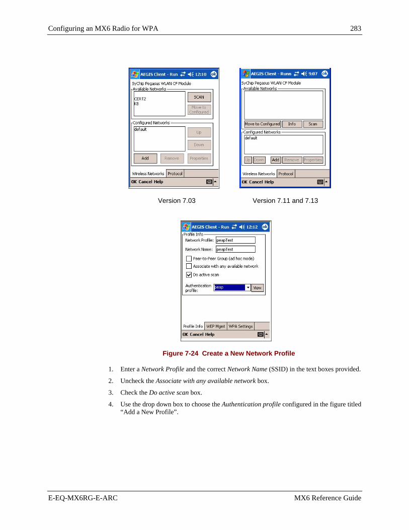
Configuring an MX6 Radio for WPA 283
E-EQ-MX6RG-E-ARC MX6 Reference Guide
Version 7.03 Version 7.11 and 7.13
Figure 7-24 Create a New Network Profile
1. Enter a Network Profile and the correct Network Name (SSID) in the text boxes provided.
2. Uncheck the Associate with any available network box.
3. Check the Do active scan box.
4. Use the drop down box to choose the Authentication profile configured in the figure titled “Add a New Profile”.

284 Configuring an MX6 Radio for WPA
MX6 Reference Guide E-EQ-MX6RG-E-ARC
Configure Radio Profile WPA Settings
Figure 7-25 Set the WPA Mode
At the bottom of the screen choose the WPA Settings tab and set the WPA Mode to WPA 802.1X.
Tap OK.
The user radio is now configured and authenticated.
Figure 7-26 Radio is Authenticated

Configuring an MX6 Radio for WPA 285
E-EQ-MX6RG-E-ARC MX6 Reference Guide
Add Server Authentication /Validation to User Profile
At the bottom of the screen choose the Server tab. The Server identity page allows you to set the credentials used for validating the authentication server during TLS and PEAP message exchange. The Client will use this information to verify that the authentication server with which the Client is communicating is a trusted server.
The fields in the Server identity dialog have the following meaning:
Do not validate server certificate chain If enabled, the server certificate will not be validated. Security is significantly reduced if the server certificate is not validated.
Certificate issuer must be Select the Certificate Authority which signed the server certificate, or select "Any Trusted CA" (the default). If the certificate authority that issued the server certificate is not listed, the CA certificate must be installed.
Allow intermediate certificates (default) Allow unspecified certificates to be in the server certificate chain between the server certificate and the specified “Certificate issuer”.
Server name must be The server name, or a domain to which the server belongs, depending on which of the two fields below has been checked. This will be compared to the server certificate's “Subject: CN” field.
• Server name must match exactly – When selected, the server name entered must match exactly the server name found on the certificate.
• Domain name must end in specified name – When selected, the server name field identifies a domain and the certificate must have a server name belonging to this domain or to one of its sub-domains.

286 Configuring an MX6 Radio for WPA
MX6 Reference Guide E-EQ-MX6RG-E-ARC
Figure 7-27 Server Certificate
1. Uncheck the Do not validate server certificate chain box.
2. The Certificate issuer must be listed in the list box. This is the certificate that was added previously in section titled “Install Certificates on the MX6”.
3. Server name must be – type the common name of the RADIUS server certificate exactly using upper and lower case as needed. This is the name of the certificate that was added previously in section titled “Install Certificates on the MX6”.
4. Tap the radio button for Must match exactly.
5. Tap the OK box at the bottom of the screen.
6. Soft reset (reboot) the MX6.
7. The MX6 will authenticate WPA, validating the server certificate first.
WPA using EAP-TLS has been configured, authenticated and validated.

Configuring an MX6 Radio for WPA 287
E-EQ-MX6RG-E-ARC MX6 Reference Guide
WPA-PSK Radio Configuration PSK does not require digital certificates.
WPA-PSK Process
• set up the radio profile to connect to AP network
• configure radio profile WPA settings
PSK – Pre-Shared Key
Setup Radio Profile to Connect to Network
Tap the SyChip Pegasus WLAN CF Module and choose Configure.
Figure 7-28 Configure SyChip Pegasus WLAN CF Module
Tap the Add button to add a network profile.

288 Configuring an MX6 Radio for WPA
MX6 Reference Guide E-EQ-MX6RG-E-ARC
Version 7.03 Version 7.11 and 7.13
Figure 7-29 Create a New Network Profile
1. Enter a Network Profile and the correct Network Name (SSID) in the text boxes provided.
2. Uncheck the Associate with any available network box.
3. Check the Do active scan box.

Configuring an MX6 Radio for WPA 289
E-EQ-MX6RG-E-ARC MX6 Reference Guide
Configure Radio Profile WPA Settings
Figure 7-30 Set the WPA PSK Mode
At the bottom of the screen choose the WPA Settings tab and set the WPA Mode to WPA PSK.
The PSK pass-phrase must be the same as the AP pre-shared key.
Tap OK. The user radio is now configured and authenticated.
WPA using WPA PSK has been configured and authenticated.

290 Configuring an MX6 Radio for WPA
MX6 Reference Guide E-EQ-MX6RG-E-ARC

E-EQ-MX6RG-E-ARC MX6 Reference Guide
Appendix A Key Maps
35-Key Numeric-Alpha Keypad
Use the soft keypad to enter characters that are not available using the 35-key keypad.
Press These Keys and Then … To Get This Key / Function
Blue Red Ctrl Alpha Sft Caps Lock
Press This Key
Power / Suspend Power
Windows Start Menu x Bksp
Keypad Backlight Toggle Backlight
Volume Up x Up Arrow
Volume Down x Down Arrow
Blue Mode Blue
Red Mode Red
Shift Sft
Alt Alt 1
Ctrl Ctrl 2
Scan Scan
Esc Esc
Space Space
Enter Ent
CapsLock (Toggle) x
x
OR
double-tap the Sft key
Back Space Bksp
Tab Tab
BackTab N/A
Break N/A
Pause N/A
Up Arrow Up Arrow
Down Arrow Down Arrow
Right Arrow Right Arrow
Left Arrow Left Arrow
Insert N/A
1 ALT and CTRL are not “sticky” keys. Press and hold these keys while pressing the next key.

292 35-Key Numeric-Alpha Keypad
MX6 Reference Guide E-EQ-MX6RG-E-ARC
Press These Keys and Then … To Get This Key / Function
Blue Red Ctrl Alpha Sft Caps Lock
Press This Key
Delete Del
Home N/A
Page Up x Up Arrow
Page Down x Down Arrow
F1 F1
F2 F2
F3 F3
F4 F4
F5 F5
F6 F6 2
F7 x F1
F8 x F2
F9 x F3
F10 x F4
F11 x F5
F12 x F6
a x 2
b x 2,2
c x 2,2,2
d x 3
e x 3,3
f x 3,3,3
g x 4
h x 4,4
i x 4,4,4
j x 5
k x 5,5
l x 5,5,5
m x 6
n x 6,6
o x 6,6,6
p x 7
2 Pressing F6, F7 or F11 produces Windows messages. See Chapter 3 “Physical Description and Layout “ section titled “Function Keys” for explanation and instruction.

35-Key Numeric-Alpha Keypad 293
E-EQ-MX6RG-E-ARC MX6 Reference Guide
Press These Keys and Then … To Get This Key / Function
Blue Red Ctrl Alpha Sft Caps Lock
Press This Key
q x 7,7
r x 7,7,7
s x 7,7,7,7
t x 8
u x 8,8
v x 8,8,8
w x 9
x x 9,9
y x 9,9,9
z x 9,9,9,9
A x x 3 x 2
B x x x 2,2
C x x x 2,2,2
D x x x 3
E x x x 3,3
F x x x 3,3,3
G x x x 4
H x x x 4,4
I x x x 4,4,4
J x x x 5
K x x x 5,5
L x x x 5,5,5
M x x x 6
N x x x 6,6
O x x x 6,6,6
P x x x 7
Q x x x 7,7
R x x x 7,7,7
S x x x 7,7,7,7
T x x x 8
U x x x 8,8
V x x x 8,8,8
W x x x 9
3 Either press SFT or activate CapsLock when capital letters are needed.

294 35-Key Numeric-Alpha Keypad
MX6 Reference Guide E-EQ-MX6RG-E-ARC
Press These Keys and Then … To Get This Key / Function
Blue Red Ctrl Alpha Sft Caps Lock
Press This Key
X x x x 9,9
Y x x x 9,9,9
Z x x x 9,9,9,9
1 1
2 2
3 3
4 4
5 5
6 6
7 7
8 8
9 9
0 0
< Use Soft Keypad
[ Use Soft Keypad
] Use Soft Keypad
> Use Soft Keypad
= Use Soft Keypad
{ Use Soft Keypad
} Use Soft Keypad
/ x F3
- x Del
+ x Space
: (colon) x F2
; (semicolon) x F1
. (period) x 1
? x 1,1,1,1
` Use Soft Keypad
_ (underscore) x F5
, (comma) x 1,1
‘ (apostrophe) x 1,1,1
~ (tilde) Use Soft Keypad
\ x F4
| Use Soft Keypad
“ Use Soft Keypad

35-Key Numeric-Alpha Keypad 295
E-EQ-MX6RG-E-ARC MX6 Reference Guide
Press These Keys and Then … To Get This Key / Function
Blue Red Ctrl Alpha Sft Caps Lock
Press This Key
! x 1
@ x 2 or Blue+F6
# x 3
$ x 4
% x 5
^ x 6
& x 7
* x 8
( x 9
) x 0 (zero)
Inactive Keys on the 35-key Keypad
Contrast Up Contrast Down Send and End

296 56-Key Full Alpha Numeric Keypad
MX6 Reference Guide E-EQ-MX6RG-E-ARC
56-Key Full Alpha Numeric Keypad
Use the soft keypad to enter characters that are not available using the 56-key keypad. Keypress Sequences for Batch Units
Press These Keys and Then …
To Get This Key / Function Blue Red Ctrl Alt Shift Caps
Lock Press This Key
Power / Suspend Power
Windows Start Menu x U
Keypad Backlight (Toggle) Backlight
Volume Up x Up Arrow
Volume Down x Down Arrow
Blue Mode Blue
Red Mode Red
CapsLock (Toggle) x Sft or press Sft twice
Shift Sft
Alt Alt 4
Ctrl Ctrl 5
Scan Scan
Esc Esc
Space Sp
Enter Ent
Back Space Bksp
Tab Tab
BackTab N/A
Break N/A
Pause N/A
Print Screen N/A
Scroll Lock N/A
Up Arrow Up Arrow
Down Arrow Down Arrow
Right Arrow Right Arrow
Left Arrow Left Arrow
Insert Ins
Delete Del
4 ALT and CTRL are not “sticky” keys. Press and hold these keys while pressing the next key.

56-Key Full Alpha Numeric Keypad 297
E-EQ-MX6RG-E-ARC MX6 Reference Guide
Press These Keys and Then … To Get This Key / Function
Blue Red Ctrl Alt Shift Caps Lock
Press This Key
Home N/A
Page Up x Up Arrow
Page Down x Down Arrow
F1 x A
F2 x B
F3 x C
F4 x D
F5 x E
F6 5 x F
F7 6 x G
F8 x H
F9 x I
F10 x J
F11 6 x K
F12 x L
F13 x M
F14 x N
F15 x O
F16 x P
F17 x Q
F18 x R
F19 x S
F20 x T
F21 x U
F22 x V
F23 x W
F24 x X
a A
b B
c C
d D
e E
5 Pressing F6, F7 or F11 produces Windows messages. See Chapter 3 “Physical Description and Layout“ section titled “Function Keys” for explanation and instruction.

298 56-Key Full Alpha Numeric Keypad
MX6 Reference Guide E-EQ-MX6RG-E-ARC
Press These Keys and Then … To Get This Key / Function
Blue Red Ctrl Alt Shift Caps Lock
Press This Key
f F
g G
h H
i I
j J
k K
l L
m M
n N
o O
p P
q Q
r R
s S
t T
u U
v V
w W
x X
y Y
z x Y
A x A
B x B
C x C
D x D
E x E
F x F
G x G
H x H
I x I
J x J
K x K
L x L
M x M
N x N

56-Key Full Alpha Numeric Keypad 299
E-EQ-MX6RG-E-ARC MX6 Reference Guide
Press These Keys and Then … To Get This Key / Function
Blue Red Ctrl Alt Shift Caps Lock
Press This Key
O x O
P x P
Q x Q
R x R
S x S
T x T
U x U
V x V
W x W
X x X
Y x Y
Z 6 x Y
1 1
2 2
3 3
4 4
5 5
6 6
7 7
8 8
9 9
0 0
. (DOT) DOT
< x , (comma)
[ Use Soft Keypad
] Use Soft Keypad
> x . (DOT)
= Use Soft Keypad
{ Use Soft Keypad
} Use Soft Keypad
/ Use Soft Keypad
- x , (comma)
+ x . (DOT)
6 Caps Lock must be On.

300 56-Key Full Alpha Numeric Keypad
MX6 Reference Guide E-EQ-MX6RG-E-ARC
Press These Keys and Then … To Get This Key / Function
Blue Red Ctrl Alt Shift Caps Lock
Press This Key
* x 8
: (colon) x F
; (semicolon) x A
. (period) . (DOT)
? Use Soft Keypad
` Use Soft Keypad
_ (underscore) x E
, (comma) Comma key
‘ (apostrophe) Use Soft Keypad
~ (tilde) Use Soft Keypad
\ Use Soft Keypad
| Use Soft Keypad
“ Use Soft Keypad
! x 1
@ x B or Sft + 2
# x 3
$ x 4
% x 5
^ x 6
& x 7
( x 9
) x 0 (zero)

E-EQ-MX6RG-E-ARC MX6 Reference Guide
Appendix B Technical Specifications
Physical Specifications
Features Specifications Comments
CPU Intel Xscale PXA255 Processor 400 MHz
Memory ROM 32 MB Flash Non-Volatile RAM 64 MB of SDRAM System Memory
Display LCD TFT Color Transflective LCD with touchscreen. Customer Configurable Backlighting
Mass Storage Secure Digital memory slot Optional – 64m, 128m, 256m SD cards
WLAN Interface IEEE 802.11b DSSS WLAN radio WiFi Compliant
Weights Unit with WLAN radio, battery and scanner endcap
20.2 oz 573 g
Batch Unit 19.7 oz 558 g
External Connectors/Interface
IrDA Connector (COM 3 / COM 6) bi-directional half-duplex
Supports 115k baud
USB and Serial 17-pin COM 1 USB communication at 12Mbps RS-232 speed 115kbps Power out at 500mA at 5V
Audio/Microphone Connector
Audio Jack
Dimensions Length 9.6” 24.53 cm Width 3.4” 8.76 cm Depth 1.6” 4.29 cm
Imager or Laser Scanner Proprietary scan engine/algorithm 1D and 2D barcodes
Batteries Main Li-Ion battery pack 7.4V 14.8Ah
In-Unit Chargeable or Externally Chargeable
Backup (CMOS)
NiMH 5.7V max.
Automatically charges from main battery during normal operation. MX6 must be connected to an external power supply when backup battery charging is required. Memory operational for 40 hours when main battery is depleted

302 Display Specifications
MX6 Reference Guide E-EQ-MX6RG-E-ARC
Display Specifications
Type Color TFT or Monochrome LCD Resolution 320 x 240 pixels Size 1/4 VGA portrait Diagonal Viewing Area 3.8 in (150.4mm) Dot Pitch 0.22mm Dot Size 0.20mm x 0.20mm Color Scale Reflective – 256 colors
Environmental Specifications
MX6 Operating Temperature 14°F to 122°F (-10°C to 55°C) Storage Temperature -22°F to 176°F (-30°C to 80°C) Water and Dust IP64 Operating Humidity Up to 90% non-condensing at 104°F (40°C) Approvals / Standards See “MX6 User’s Guide”, Appendix B. Contamination Resistant to exposure to skin oil and other lubricants. Vibration Based on MIL Std 810D ESD 15kV direct contact Shock Multiple 1.5m (5’) drops to concrete.
AC Wall Adapter Input Power Switch None Power "ON" Indicator LED Input Fusing Thermal Fuse Input Voltage 100VAC min – 240 VAC max Input Frequency 50 - 60 Hz Input Connector North American wall plug, no ground Output Connector 26 position D serial interface Output Voltage +12VDC, unregulated Output Current 0 Amps min, 3.75 A max Operating Temperature 32° F to 104° F / 0° C to 40° C Storage Temperature -13° F to 158° F / -25° C to 70° C Humidity Operates in a relative humidity of 5 – 95% (non-condensing)

Scanner Specifications 303
E-EQ-MX6RG-E-ARC MX6 Reference Guide
Scanner Specifications
Imager Decode Zone
Engine Imager Decode Zone
SR 2.5 to 12.5 in. / 6.3 to 32 cm
Laser Decode Zones
Engine Scanner Decode Zone
5 mil barcodes from 2.75 to 7 in. / 0.07 to 0.17m HP
55 mil reflective barcodes from 5 to 50 in. / .13 to 1.26m
10 mil barcodes from 10 to 24 in. / 0.25 to .6m LR
100 mil reflective barcodes from 66 to 232 in. / 1.67 to 5.9m
13 mil barcodes from 18 to 39 in. / 0.45 to 1m ALR
100 mil reflective barcodes from 102 to 363 in. / 2.6 to 9.2m
Barcode Symbologies
Can be decoded by … Can be decoded by … Barcode Symbology Imager Scanner
Barcode Symbology Imager Scanner
Auspost x Int25 x x Aztec x ISBT x x BPO x JapanPost x Canpost x Maxicode x Codabar x x Mesa x Codablock x MicroPDF x Code11 x x MSI x x Code128 x x OCR x Code39 x x PDF417 x Code49 x Planet x Code93 x x Postnet x Composite x QR x DataMatrix x RSS x x DutchPost x TLC x EAN13 x x UPCA x x EAN8 x x UPCE0 x x IATA25 x x UPCE1 x x

304 Scanner Specifications
MX6 Reference Guide E-EQ-MX6RG-E-ARC
Communication Port Specifications See section titled “COM Ports” in Chapter 3 “Physical Description and Layout”.
USB communication at 12Mbps RS-232 speed 115kbps Power out at 500mA at 5V
COM 1 17-pin Serial Port RS-232 Port, USB and Power Connection
Serial Port Pinout
PIN SIGNAL PIN SIGNAL 1 + USB 10 - USB 2 PWR 11 USB DET 3 N / C 12 RI 4 N / C 13 DSR 5 N / C 14 RXD 6 N / C 15 RTS 7 GND 16 TXD 8 5V OUT 17 CTS 9 DTR
COM 3 / 6 The IR operating envelope has a distance range of 2 cm (.79 inches) to 15 centimeters (6 inches) with a viewing angle of 30 degrees.
COM 3 IR Port Raw Infrared communication
COM 6 IrDA Port Infrared communication using IrDA protocol

Revision History 305
E-EQ-MX6RG-E-ARC MX6 Reference Guide
Revision History
Revision D – Released October 2005 (Documents Kernel 7.03 vs 7.11 Changes)
• Chapter 1 Introduction -- Removed obsolete tethered scanners from “Accessories”. Added section titled “Revision History”.
• Chapter 2 Getting Started -- Added “Saving Your Changes”. Removed “Setting Wireless Security” and referred reader to “Chapter 7 Wireless Network Configuration”.
• Chapter 3 Physical Description and Layout -- Added “Upgrading the Mobile Device OS.” Updated keypad figure. Updated section titled “Function Keys.” Added WEEE statement to “Battery” and to “Notices.”
• Chapter 4 System Configuration -- Updated Control Panel options to reflect changes in Ver 7.03 versus Ver 7.11 image releases:
Scanner/Keyboard Wedge, Headset Control, Clock, Regional Settings, Owner Information, Password, Sounds and Notifications, Screen, 802.11 Settings, Pegasus Settings, Network Cards.
Added sections titled “WaveLink Avalanche Enabler”, “Version 7.XX” (where appropriate), and “Hat Encoding”, “Decimal-Hexadecimal Chart” for the Scanner/Keyboard Wedge Advanced tab options,
• Chapter 6 Scanner / Imager Parameter Setup -- Enabled RSS symbologies for laser scanner. Disabled Code 39 Append Mode.
• Chapter 7 Wireless Network Configuration -- Added new chapter containing WPA information and instruction.
Important:
LXE recommends that all radio configuration be performed using either the 802.11b settings tab or the Meetinghouse AEGIS Client security supplicant, they should not both be configured at the same time.
• Appendix A Keymaps -- Added function keys F7 through F12 to the 35-key keypad.
Revision C – Released February 2005
• Entire Manual -- Removed Pocket PC 2002 information. Retained Windows Mobile information. Placed Pocket PC 2002 information in the MX6 PPC Reference Guide (E-EQ-MX6PCRG-[Rev]).
• Chapter 2 Getting Started -- Added WPA to “Setting Wireless Security” section.
• Chapter 5 AppLock -- Added new chapter and explanation of AppLock.
• Chapter 6 Scanner Imager Parameter Setup -- Removed this section from Chapter 4 “System Configuration” and created a separate chapter.
Revision B – Released August 2004
• Entire Manual -- Added instruction/information for devices shipped with a Barcode Laser Scanner (high performance [SR], long range [LR], and advanced long range [ALR] ). Added warnings about not allowing backup battery to deplete/die or else device will revert to default settings. Added instruction/information for devices shipped with Windows Mobile for Pocket PC operating system.
• Chapter 1 Introduction -- Added tethered scanners to Accessories.

306 Revision History
MX6 Reference Guide E-EQ-MX6RG-E-ARC
• Chapter 4 System Configuration -- Added section “The SCANNER.INI File”. Note that this chapter contains system configuration information for the MX6 running Windows Mobile for Pocket PC only.
• Appendix C Pocket PC 2002 System Configuration -- Split Revision A’s Chapter 4 “System Configuration” into Pocket PC 2002 and Windows Mobile for Pocket PC. Windows Mobile for Pocket PC is contained in Chapter 4 – System Configuration. Pocket PC 2002 System Configuration is contained in Appendix C for MX6 backward compatibility.
Revision A – Initial Release, December 2003

E-EQ-MX6RG-E-ARC MX6 Reference Guide
Appendix C MX6 Multicharger
Introduction
The Multicharger has four slots that fully charge a main battery in four hours. The charging slots work independently to control the charging of individual battery packs. Status LEDs at each charging slot indicate battery charge process.
The right-most slot can be used for charging or charging/analyzing a battery. The charge/analyze slot has a Status LED that indicates charge status and a Battery Capacity Indicator LED that indicates analyze status. The analyze slot begins the analyze process on the battery if the Analyze button is pressed once the battery has been seated in the slot.
LXE recommends all MX6 battery packs be Analyzed on a monthly basis. Analyzing will reset the internal battery charge indicator circuit, "the gas gauge", as well as analyze the battery.
The multicharger must be connected to an AC power source and the power switch turned on before charging/analyzing can occur.
The multicharger should be located in an area where it:
• Is not in high traffic areas.
• Has enough clearance to allow easy access to the power and ports on the back of the device.
• Is protected from rain, dust or inclement weather. This device is intended for indoor use only.

308 Using the Multicharger
MX6 Reference Guide E-EQ-MX6RG-E-ARC
Using the Multicharger
Note: For best results, battery packs should be at room temperature before recharging them; temperature has a marked effect on charging. The recommended temperature range is 50° to 95° F (10 ° to 35 ° C).
Figure C-1 MX6 Multicharger Components
1 Battery Capacity Indicator LED - Analyze 2 Analyze Button 3 Charge/Analyze Slot 4 Charging Slots 5 AC Power Jack (not seen) 6 Power Switch (not seen) 7 Charge Status LEDs
1. Push the barrel connector into the power jack at the back of the multicharger.
2. Plug the three prong connector end of the AC power supply into an AC wall outlet.
3. Toggle the Power switch to On.
4. The green power LED illuminates and the charger performs a self-diagnostic test that lasts approximately 5 seconds.
The multicharger is ready for use.
Inserting/Removing a Battery Pack Do not "slam" or drop the battery into the slot. Failure to follow this instruction can result in damage to the battery or the multicharger.
Place the end of the battery pack without the locking tab into the bottom of the charging slot and snap the battery into place with a hinging motion. The status LED for that slot illuminates orange when the battery has been properly inserted.
Remove the battery pack by pushing the locking tab down and then pulling the battery out of the slot with a hinging motion.

Using the Multicharger 309
E-EQ-MX6RG-E-ARC MX6 Reference Guide
Charging As soon as a battery pack is placed in any slot, charging begins and the Status LED illuminates.
Green Charge cycle completed and battery is ready for use.
Orange Charge cycle is progressing.
Red Battery or charge slot encountered an error during the recent charge cycle.
Analyzing Note: Because the multicharger is accumulating battery pack information during the entire
Analyze cycle, it is important not to remove the battery until the cycle has been completed.
Insert a battery into the right-most slot (the slot next to the Analyze button).
Press the Analyze button.
The Analyze cycle begins. Only the battery in the Charge/Analyze slot is analyzed.
In an Analyze cycle, batteries are completely discharged and then recharged to capacity. The indicator LEDs display just what that capacity is at the end of the cycle. The battery is completely reset and re-calibrated. Resetting and calibrating batteries on a regular basis can provide longer and more consistent performance from those batteries.
The length of time it takes for a battery to run through the complete Analyze cycle varies depends on initial state of the battery.
Minimum time is 8 hours, maximum time is 12 hours.
The Charge/Analyze slot also contains a Status LED in the upper, left corner of the slot. When this slot is used for regular charging, this LED operates in the usual manner.
Battery Capacity Indicator LEDs The Battery Capacity Indicator LEDs are located along the right side of the Charge/Analyze slot. The LEDs illuminate after the completion of the Analyze cycle. Upon the completion of the final charge, the LEDs display the measured capacity of the battery. Battery capacity is displayed as a percentage of measured capacity/rated capacity. Each LED equates to 10% battery capacity.
Analyzer Slot Status LED When this slot is being used to analyze a battery, the Status LED functions as follows:
Solid Green Has completed the Analyze cycle.
Flashing Orange Is being analyzed.
Solid Red Encountered an error during the Analyze cycle.

310 Technical Specifications
MX6 Reference Guide E-EQ-MX6RG-E-ARC
Technical Specifications
Operating Temperature 14°F to 122°F (-10°C to 50°C) Storage Temperature -4°F to 158°F (-20°C to 70°C) Charging Temperature 32°F to 113°F (0°C to 45°C) Weight 18 oz (510 g) Dimensions Length 11.7 in x Width 5.2 in x Height 1.5 in
Length 29.7 cm x Width 13.2 cm x Height 3.8 cm Capacity 1 to 4 battery packs Power Supply Input 90-265V, 47-63Hz Power Supply Output 12VDC, 3A Input Connection 2 position IEC 320-C8 Charging Mode: Standard 100% charge in 4 hours Charging Mode: Analysis Charges/discharges/resets/calibrates battery in 14 hours
Troubleshooting
Problem Issue
The Charging LED does not come on when a battery pack is locked into a slot.
Check the AC power connection; make sure the power switch is ON and the battery pack is properly seated.
The red status LED comes on during charging.
Try to charge the battery in one of the other charging slots. If the red Status LED comes on again, then the problem is associated with the battery pack. If the red status stays with the charging slot, the problem is associated with the charging circuitry.
The red status LED remains on without a battery in the charging slot.
An error occurred during the self-diagnostic test for that particular charging slot. Contact LXE Technical Services.
‘

E-EQ-MX6RG-E-ARC MX6 Reference Guide
Index
2D Matrix barcode, how to scan ...........................28 802.11b Preamble mode..........................................129, 147
A About ..................................................................102 About Pegasus Settings................................................130
About Pegasus Settings................................................148
About Pegasus..............................................................148
Accessing Files in Flash Memory.........................21 Accessories and User Guides................................11 Activation Key....................................................222 Active SSIDs ......................................................143 Version 7.03......................................................128
ActiveSync Cables..................................................................31 Configure ............................................................30 Connect ...............................................................31 initial setup..........................................................30 partnership...........................................................30 serial connection .................................................30 Synchronizing from the MX6 .............................63 USB connection ..................................................31
ActiveSync Help...................................................63 ActiveSync Setup Wizard...............................30, 62 ActiveSync version 3.7 .........................................62 Add a CAB file .....................................................21 Adjust input options............................................117 Admin Hotkey AppLock ...........................................219, 221, 229
Administration mode AppLock ...........................................................217
Administrator mode EZConfig ..........................................................164
Advanced Version 7.03......................................................123
AEGIS Using LEAP and WEP......................................132
AEGIS client and LEAP....................................................67, 156 and WEP .....................................................67, 156 Getting started.....................................................67
AEGIS Client Icon Indicator ................................66
AEGIS Client main screen....................................68 Aim scan beam, how to.........................................28 Align the touch screen ..................................16, 117 Alpha key..............................................................45 Alt DNS, network adapter ..................................138 Alt WINS, network adapter ................................138 Anti-static protection is required ..........................35 AP Density .................................................134, 157 AP Search Threshold................134, 135, 157, 159 Application Panel................................................221 applications forcibly closed ..................................40 AppLock EUIE .................................................................222
AppLock ...............................................................57 End-user mode ..................................................219 Passwords..........................................................220 Setup .................................................................217
AppLock Registry settings................................................240
Arrow keys ...........................................................46 Assign IP Address and Name Servers to a Network Adapter........................................154
Assigned Replacement Block and key message mode ...........................114
Associating Applications EZConfig ..........................................................171
Audio ....................................................................48 Audio interface .....................................................34 Audio jack, How to.........................................12, 22 Authentication Algorithm...........................135, 159 Authentication Profile...........................................77 Authentication Timeout ........................................75 AutoInstall ..........................................................177 AutoInstall folder..................................................21 Autorun and Autoinstall......................................173 Autorun Configuration File ................................173 Autorun.ini file ...................................................188 Auxiliary Battery Well..........................................53 available networks ................................................74
B Backlight change settings ..................................................103
Backlight intensity ................................................19 Backlight, Display ................................................18 Backlight, Keypad ................................................45

312 Index
MX6 Reference Guide E-EQ-MX6RG-E-ARC
Backspace key ......................................................45 Backup Battery Time Limit ..........................................................50
Backup battery requires frequent external power charging ............................................................43
Barcode images, how to........................................26 Barcode Scanner ...................................................26 Barcode Symbologies .................................204, 244 Barcode Symbologies supported.........................303 Barcode symbology validated...............................38 Barcodes .....................................................204, 244 Battery Backup ................................................................51 charge time..........................................................13 Dead condition ....................................................14 Handling Safety ..................................................50 Icon, low battery .................................................14 Important need to know ........................................2 locking tab...........................................................14 replace, how to ....................................................14 view battery charge status ...................................83
Battery icon...........................................................49 Battery Life Approximate .......................................................50
Battery Management Procedure Publication ..........................................................51
Battery power bar ...............................................107 Battery, Main ........................................................49 BattMon................................................................83 Beam, IR receiving .....................................121, 149 BSS ID Pegasus......................................................125, 141
C CAB file................................................................21 CAB file install .....................................................21 Cables ActiveSync Configuration...................................31
Calculator icon......................................................64 Calibrate or align the touch screen................16, 117 CertAdd ........................................................80, 260 Certificate Authority (CA)....................................80 Certificate Installer ...............................................80 Certificates Install how to.....................................................260
Certificates icon ..................................................104 Change the date and time..............................17, 259 Channel.......................................................135, 158 Character Recognition ..........................................98 Charger slot sensor ...............................................52 Check the battery status ......................................103 Cleaning the touch screen and imager aperture ....47 Clear Type Tuner................................................104 Client
EZConfig ............................................................84 Supplicant .................................................257, 258
Client Configuration Server tab ............................................................72 System tab...........................................................71 User tab ...............................................................70
Client Menu ..........................................................69 Client or Certificate Authority (CA)...................260 Clock...................................................................259 change settings ..................................................105
Clock, setting date and time..................................17 closed loop fastener ..............................................24 Cold boot ..............................................................40 COM 1 port...........................................................36 COM 3 and COM 6 port .......................................36 COM 3 or COM 6.................................................39 COM Ports............................................................36 Command line args DeviceConfig ....................................................189
Components ............................................................3 Configuration AppLock ...........................................................221 Single User AppLock........................................229
Configuration files EZConfig ..........................................................163
Configure a Network Adapter.....................124, 154 Configure Menu Option........................................70 Configure Network Adapter Version 7.03......................................................124
Configure the WEP Key .............................135, 159 Connections Advanced tab ............................................122, 151 Radio Manager..........................................131, 155 Tasks tab ...................................................122, 150
Connections menu ..............................................139 Version 7.03......................................................120
Contact LXE .........................................................11 Control characters...............................................113 Control Panel Single User AppLock........................................229
Core Logic ............................................................34 CPU ......................................................................33 CPU speed adjustment ........................................105 Cradle sensor ........................................................53 Create a new profile...................................133, 157 Creating and modifying profiles, How to ...........156 Ctrl and Alt keys...................................................46 Current Time.......................................................105 Cursor keys ...........................................................46
D Data entry .............................................................25 Date and time................................................17, 259 Daylight savings time ...................................17, 259

Index 313
E-EQ-MX6RG-E-ARC MX6 Reference Guide
Dead battery..........................................................43 Decimal - Hexadecimal Equivalent 0 - 159 ...............................................................215 160 - 255 ...........................................................216
Decode zones ........................................................27 Decode Zones, Imager and Laser........................303 Decoder...............................................................242 Default AP Search threshold ...............................134, 157 Backlights .........................................................103 Beam .........................................................121, 149 Certificates ........................................................104 Clock.................................................................105 CPU speed.........................................................105 IP Address and Name Server ....................124, 154 IpConfig ..............................................................85 Memory allocation ............................................106 Network Adapter...............................................138 OS Password .....................................................100 Ping
Input, output, about ........................................87 Power ................................................................107 Profile Info ..........................................................76 Protocol authentication timeouts.........................75 Regional Setting................................................108 Route...................................................................93 Scanner settings ................................................109 Start Menus .........................................................98 WEP Mgmt .........................................................77 WPA Settings......................................................79
Default Gateway, network adapter .....................138 Default headset volume ........................................97 Defaults Internet Explorer .................................................65 Start Menu...........................................................59
Delete key .............................................................45 Delete Programs..................................................108 Deleting a profile, how to ...........................136, 160 Demo program listing ...........................................64 DemosMenu........................................................178 Desktop.................................................................59 Desktop Cradle .....................................................53 Device information .............................................102 DeviceConfig......................................................182 Dialing ........................................................122, 150 Dim Backlight if device is not used for ................19 Dimensions .........................................................301 Direction keys.......................................................46 Disable internal scanner when ............................109 Disable WEDGE when .......................................109 Display Features...............................................................47 Pixels...................................................................47 Specifications....................................................302
Display Backlight .................................................18 Display backlight and keypad backlight ...............18
Display Backlight and the Power Off timers ........43 Display Backlight Timer.......................................47 Display controller .................................................34 Display EAP Notifications....................................75 Display full configuration button..........................85 Display Timer .......................................................47 DNS, network adapter ........................................138 Do active scan.......................................................76 Dock LED Cradles ................................................................53
Docking cradles ....................................................53
E Edit Keys EZConfig ..........................................................169
Edit Menu EZConfig ..........................................................167
Edit Start Menu Item List .....................................60 Edit the Autorun Configuration File ...................175 Edit the terminal emulation parameters ................13 Editor EZConfig ............................................................84
Enable ClearType .......................................117, 119 Enabling and Disabling Sections ........................174 Encrypted Sections and Keys .............................164 encryption .............................................................77 Encryption Key...........................................135, 159 End user switching Hotkey...............................................................227 Touch ................................................................227
Enter an SSID .............................................135, 158 Enter key...............................................................45 Entering Data ........................................................25 Environmental Specifications AC Wall Adapter ..............................................302 MX6..................................................................302
Error Messages AppLock ...........................................................233
Escape key ............................................................45 Excel .....................................................................81 Existing profile ...........................................134, 158 EXM files and INI files ......................................163 External power supply ..........................................15 EZConfig Client.................................................................161 Editor ................................................................161 Menu Options....................................................161 Utilities..............................................................161
EZConfig Editor How To .............................................................163
EZConfig Menu..................................................190 EZConfig Utilities ................................................84
314 Index
MX6 Reference Guide E-EQ-MX6RG-E-ARC
F Failure Battery Pack ........................................................51
Features...................................................................1 File Explorer icon .................................................64 File Menu EZConfig ..........................................................166
Find function.........................................................64 Flash memory .......................................................34 Flash Specifications ..............................................34 Function keys F6 F7 and F11 ...............................46
G Games ...................................................................65 Getting Help .........................................................11 Getting started.......................................................13 Getting the Most from Your Batteries ..................51 Global Delay.......................................................222 Global Key..........................................................222 GTC (Generic Token Card) ................................270
H Handling Batteries ................................................50 Handstrap hook.....................................................14 Handstrap, adjusting .............................................24 Hard reset..............................................................40 Hardware Configuration ......................................................33
Hat Encoded Characters......................................213 Headset .................................................................48 Help ......................................................................11 Help function ........................................................65 Hexadecimal - Decimal Equivalent 0x00 to 0x9F .....................................................215 0xA0 to 0xFF ....................................................216
Hot Swapping Main Battery .................................50 Hotkey AppLock ...........................................................223 Single User AppLock........................................230
I I/O components.....................................................34 Icons .......................................................................9 IEC IP64 .............................................................302 ImageDemo ........................................................191 Imager Demo...................................................................64 Integrated ............................................................38
Imager aiming beam .............................................28
Imager decode zones.............................................38 Imager/Scanner/Symbology Quick Reference204, 244 Images and screen captures, how to......................26 Import INI...........................................................166 Important battery warning ......................................2 Inactive keys .........................................................44 35-key keypad...................................................295
Inbox.....................................................................65 Indicators and LEDs Cradles ................................................................54
Infrared Data Access (IrDA).................................39 Infrastructure ..............................................135, 158 INI files and EXM files ......................................163 Input method, soft keypad ....................................98 Input methods Keyboard, soft keypad ........................................98
Input panel show and hide how to..........................................10
Insert battery .........................................................14 Install ActiveSync on Desktop or Laptop.............30 Installing Certificates with CertAdd .....................80 Installing Certificates, how to.............................260 integrated imager ..................................................38 Integrated Imager..................................................26 integrated laser scanner.........................................38 Interface Options ..................................................75 International Characters........................................10 Internet Explorer AppLock ...........................................................222 Single User AppLock........................................230
Internet Explorer...................................................65 IP Address Pegasus......................................................125, 140 Ping utility.................................................126, 141
IP Address, network adapter...............................138 IPSM folder ..........................................................21 IR operating envelope...................................39, 304 IR Port bi-directional half-duplex....................................39
IrDA and ActiveSync ...................................................31
J JAVA....................................................................56 JEM-CE ................................................................56
K Key ID ........................................................135, 159 Key Index and Transmit Key................................78 Key map 35-key keypad...................................................291 56-key keypad...................................................296

Index 315
E-EQ-MX6RG-E-ARC MX6 Reference Guide
Keyboard shortcuts .................................................9 Keyboard Status utility .........................................86 Keyboard Wedge Control ...................................110 Keypad and entering data .....................................25 Keypad Backlight .................................................45 Keypad graphics ...................................................44 Keys and Sections.......................................167, 169 Keystroke, repeating .............................................10
L Laser Scanner Integrated ............................................................39
Launch Associated App......................................165 Launch in silent mode EZConfig utilities menu....................................191
LCD unit is in Suspend mode ...............................47 LED indicators docking cradles ...................................................54
Levels, Logging Single User AppLock........................................232
Link Quality Pegasus......................................................125, 140
List of controlled ports..........................................68 Lithium battery warning .........................................2 Lithium-Ion (Li-ion) .............................................49 Locked Sections and Keys..................................164 Logging AppLock ...........................................................226
Low battery condition, warning and icons............14 Low Battery Warning ...........................................51
M Main Battery and Critical Suspend state ...................................50 Hot Swapping......................................................50
Main Battery Pack ................................................50 Manage ports ........................................................68 Mass Storage.......................................................301 Meetinghouse Using LEAP and WEP......................................132
Meetinghouse AEGIS Client menu ......................66 Meetinghouse Certificate Installer ........................80 Memory adjust amount ....................................................106
Menu Options Settings................................................................95
Messenger.............................................................81 mode Block.................................................110, 112, 115 Key Message.....................................110, 112, 115
Modem........................................................122, 150 Modes
AppLock ...........................................................219 Modifier keys........................................................46 Modify an existing profile ..........................134, 158 Modify, move Sections .......................................168 MSN Messenger icon ...........................................81 Multi-Application AppLock ...............................218 Multicharger Battery Capacity Indicator LED........................309 Status LED........................................................309 Technical Specifications ...................................310 Troubleshooting ................................................310
Multicharger for MX6 battery packs ..................307 Multicharger, four bay ..........................................52 MX6 PPC vs MX6 Windows Mobile .....................2 MX6 Software Development Kit ........................109 My Documents folder ...........................................21
N Network Adapters.......................................137, 153 Network Adapters tab .........................................137 Network Cards ....................................................152 Network Menu configuration EZConfig ..........................................................193
Network Name......................................76, 135, 158 Network Profile ....................................................76 Network Utilities ..................................................86 New unit preparation ............................................13 NoSIP utility .........................................................86 Notes.....................................................................81
O OCR setup examples...........................................250 OCR string..........................................................249 Off Mode characteristics.......................................43 ON Mode characteristics ......................................42 On-line Help .........................................................55 Operating System (OS).........................................56 Operating Temperature .......................................302 US AC to DC ....................................................302
Optional Software AppLock .............................................................57 Avalanche ...........................................................57 JAVA ..................................................................56 RFTerm...............................................................56
Owner Information ...............................................99
P Parameter setup Scanner / Imager ...............................................241
Password

316 Index
MX6 Reference Guide E-EQ-MX6RG-E-ARC
Single User AppLock........................................231 Password Assignment and Sleep Timer..............100 Passwords AppLock ...........................................................220 AppLock Save As .....................................226, 232
Peer-to-Peer Group ...............................................76 Peer-to-Peer or Access Point ......................135, 158 Pegasus Active SSIDs.............................................128, 143 Add an Active SSID profile ......................127, 142 Advanced tab ............................................129, 147 Config tab..................................127, 132, 142, 156 Power save mode ......................................129, 147 Preamble mode..........................................129, 147 Preferred profiles ......................................128, 143 Refresh button...........................................127, 142
Pegasus Settings..................................................140 Version 7.03......................................................125
Personal tab Menu option ........................................................98 program hardware buttons ..................................95
Pictures .................................................................81 Ping.......................................................................87 Pegasus......................................................125, 140
Ping utility ..........................................................141 Version 7.03......................................................126
Pocket Excel .........................................................81 Pocket MSN icon..................................................81 PocketWord icon ..................................................82 Port Manager timeout ...........................................71 Port, Infrared.........................................................39 Power key .............................................................45 Power key, location ..............................................15 Power modes explained ........................................42 Power off timer settings........................................20 Power Supply Li-Ion battery pack..............................................34 NiMH backup battery..........................................34
Power Tools Introduction.........................................................57
Power Tools Menu..............................................196 Preamble mode ...........................................129, 147 Preferred List ..............................................136, 160 Preferred profiles ................................................143 Version 7.03......................................................128
Prefix and Suffix.................................................112 Pre-loaded Files ..............................................55, 56 Prerequisite WPA setup ........................................................258
Print Demo...................................................................64
PrintDemo Menu configuration ..........................200 Profile Config tab..........................................................142 deleting......................................................136, 160
Profile, Config tab ..............................................127
Profiles Creating and modifying ............................132, 156
Program Install Locations...................................177 Program Sections and Launch Sequence ............174 Programs and files in flash memory .....................21 Programs and files located in the IPSM folder .....21 Programs listing ....................................................61 Protocol selection..................................................70 Protocol tab...........................................................74 Provide encryption key dynamically ....................77 Provide Encryption Key Dynamically ..........67, 156 PSK pass-phrase ...................................................79
Q Quick start.............................................................13 Quick Start Applications.......................................60
R Radio and ActiveSync ...................................................31
Radio configuration Using LEAP and WEP......................................132
Radio manager ....................................................131 Radio Manager....................................................155 Radio Modes, Status ...................................131, 155 RADIUS server digital certificate.......................260 RAM and files are cleared ....................................40 RASMan configuration file ..................................90 RASMan icon .......................................................89 RASMan utility...................................................202 Reboot...................................................................40 Reboot icon...........................................................91 Receive all incoming beams .................................36 Receive all infrared beams....................................31 Recognizer Block...................................................................10 Letter ...................................................................10
Red or Blue keys, when to use..............................25 Reduced Power Mode and 8500 series tethered
scanners ............................................................12 RegBackup icon....................................................92 RegEdit icon .........................................................92 Registry, AppLock..............................................240 RegRestore icon....................................................93 Release the IP address button ...............................85 Remove Programs, how to..................................108 Renew IP Pegasus......................................................125, 140
Renew IP Address.................................................75 Renew the IP address button.................................85 Reset timers after suspending ..................................................43

Index 317
E-EQ-MX6RG-E-ARC MX6 Reference Guide
Reset to factory defaults .......................................40 Reset, hard ............................................................40 Reset, soft .............................................................40 Restore last saved registry settings .......................93 RFSettings configuration ....................................203 RFTerm.................................................................56 RFTerm icon.........................................................65 Right mouse click ...................................................8 Root CA digital certificate..................................260 Route icon.............................................................93 RS-232 Pinout.......................................................37 Running Programs ..............................................106
S Sample scan config file.......................................254 Save Credentials timeout ......................................71 Save your settings .................................................13 Scan Demo...................................................................64
Scan angle correct angle described........................................28
Scan buttons and tethered scanners ..........................................29
Scan for broadcasting networks ............................74 SCAN key.............................................................45 Scan LED illuminates ...........................................38 Scan Ranges..........................................................27 SCANCONFIG.INI ............................................254 ScanDemo...........................................................204 Scanner ...............................................................109 Advanced tab ....................................................111 Main tab ............................................................110 Version 7.03......................................................109
Scanner aiming beam............................................28 Scanner COM1 tab .............................................116 Scanner Control Characters Tab .........................113 Scanner decode zones ...........................................39 Scanner/Imager Parameter Setup........................241 Screen Align screen ......................................................117
Screen alignment ................................................118 SD Card Storage ................................................................35
SD cards How to install or remove.....................................35
SD memory interface cards...................................35 SDA (Secure Digital Access) ...............................22 Sections EZConfig ..........................................................167
Security Panel AppLock ...........................................................223
Security Single User AppLock ...........................230 Serial connection and ActiveSync ...................................................30
Server assigned IP Address Version 7.03......................................................124
Server certificate...................................................72 Server identity.....................................................267 Server identity dialog..........................................264 Server identity page, defined ..............................277 Set system level fields ..........................................71 Set the wireless radio parameters..........................13 SetDevice Info configuration..............................212 Settings Menu .......................................................95 Setup AppLock ...........................................................217
Setup Wireless Networks ..............................................73
Setup Scanner and Imager...........................................241
Setup a new unit....................................................13 Setup and configuration........................................55 Setup Network Profiles.........................................76 Shift key................................................................45 Shutdown time limits ............................................51 Signature Capture Demo...................................................................64
Silent Mode EZConfig ..........................................................191
Single Application AppLock ..............................218 Soft Input Panel International characters .......................................10
Soft Input Panel (SIP) ...........................................10 Soft reset ...............................................................40 Software and Files ..........................................55, 56 Software, Pre-loaded.............................................56 Speaker .................................................................48 Speaker volume, How to.......................................23 Specificiations, Comm Ports...............................304 Start menu.............................................................59 Startup Options Autorun Configuration File...............................176
Status Single User AppLock........................................231
Status Pegasus......................................................125, 140
Status LED Multicharger........................................................52
Status Panel AppLock ...........................................................225
Status tab window.......................................127, 142 Stop or start programs.........................................106 Storage Card space used .........................................................106
Storage Temperature...........................................302 US AC to DC ....................................................302
Storing SD Cards ..................................................35 Strip Leading, Strip Trailing...............................112 Stylus and data entry.............................................25 Stylus holder ...........................................................8

318 Index
MX6 Reference Guide E-EQ-MX6RG-E-ARC
Stylus replacement..................................................8 Stylus, how to .........................................................8 Subnet Mask, network adapter............................138 Suffix and Prefix.................................................112 Supplicant Client.........................................................257, 258
Suspend Keypad backlight key..........................................18
Suspend How To...................................................94 Suspend mode characteristics......................................................43
SyChip ........................................................125, 140 Symbology Quick Reference ......................204, 244 SysInfo icon..........................................................94 System Configuration ...........................................55 System Hardware Configuration...........................33 System information text file .................................94 System parameters ................................................55 System tab...........................................................102 System tray icons....................................................9
T Tab key .................................................................45 Tasks.....................................................................82 Version 7.03......................................................122
Tether, stylus ..........................................................8 Tethered scanners ...........................................29, 39 Text size, resetting ..............................................119 Time needed to charge batteries ...................................................13
Today....................................................................59 Today screen.......................................................101 Tools Menu EZConfig ..........................................................170
Touch Screen ........................................................47 and data entry......................................................25
Touch Screen calibration, align ....................16, 117 Transflective Display............................................34 Translate All .......................................................113 Translate control codes .......................................111 Troubleshooting AppLock Password ...........................................220 Multi-Application AppLock..............................228
Troubleshooting ActiveSync..........................................................30 Contrast Up and Down, Send and End................44 Hard reset loses programs and data.....................40 Unsuccessful scan ...............................................27
Troubleshooting Multicharger......................................................310
Tunneled Authentication and PEAP ...........263, 272 Turn off backlight if device is not used for...........19 Turn off device if not used for ..............................20 Turn on backlight when ........................................19
TX Transmit rate.........................................135, 158
U Up/Down button control .......................................96 upgrading drivers ..................................................41 USB connection and ActiveSync ...................................................31
Use the imager, how to .........................................26 User Certificate.....................................................70 User credentials ....................................................70 Using the client ...................................................162 Using the Editor..................................................163 Utilities EZConfig ............................................................84 MX6....................................................................83
Utils ......................................................................82
V Vehicle docking cradle .........................................53 Verify a server certificate .....................................72 Version information..............................................55 Video Subsystem Display Characteristics .......................................34
View Display ................................................................47
View Battery power bar......................................107 Virtual keyboard ...................................................10 Volume adjust audio volume ......................................23, 48
W Wake from suspend ..............................................19 Wake from Suspend mode....................................15 Warning Low Battery beeps ..............................................51
Waste Electrical and Electronic Equipment (WEEE)............................................................49
WaveLink Avalanche Enabler ........................57, 63 Weights...............................................................301 Welcome Screen section.....................................188 WEP Encryption...........................................................77 Management Key ................................................77
WEP Key ....................................................135, 159 WEP key instruction .............................................78 WEP Key Off..............................................135, 159 When cradled........................................................30 When to use this guide............................................6 Windows IP configuration ....................................85 WINS, network adapter ......................................138

Index 319
E-EQ-MX6RG-E-ARC MX6 Reference Guide
Wireless Networks tab ..........................................74 Wireless radio and ActiveSync ...................................................31
Wireless signals off and on settings....................107 Wireless tab ........................................................152 Wireless Zero Config Disable ................................................................71
WLAN CF Module .....................................125, 140 WPA not supported in Peer-to-Peer..............................76 Radio Configuration..........................................265 Settings......................................................276, 289
WPA Authentication EAP-TLS ..........................................................279 PEAP/GTC........................................................270 PEAP/MS-CHAP..............................................262 WPA-PSK.........................................................287
WPA functionality ..............................................258 WPA Mode ...........................................................79 WPA prerequisites ..............................................258 WPA Security Windows Mobile Setup.....................................257
WPA WI-Fi Protected Access ....................257, 258

320 Index
MX6 Reference Guide E-EQ-MX6RG-E-ARC