Embed Size (px)
Citation preview

Page 1 of 29 2321497B
MX Series II Operating Manual
MX Series II Modular Automation for Nano and Analytical Scale HPLC
And Low Pressure Fluid Switching Applications

Page 2 of 29 2321497B
Table of Contents Introduction.................................................................................................................... 3
Unpacking the Module ................................................................................................ 3 MX II Flowpaths ............................................................................................................. 4
Two-Position................................................................................................................ 4 Multi-position .............................................................................................................. 4
Specifications ................................................................................................................. 5 Device Specifications................................................................................................... 5
Installation ...................................................................................................................... 7 Cautions ...................................................................................................................... 7 Warnings ..................................................................................................................... 7 General Description .................................................................................................... 7 Electrical Connections ................................................................................................. 8 Communication Cable Connections............................................................................ 8 Start Signal for Data Acquisition (For 2-Position Valves only) ................................... 10 Needle Port Installation for Syringe Loading Injectors.............................................. 10
Operation ..................................................................................................................... 11 Control Panel Overview ............................................................................................ 11 Local or Manual Operation........................................................................................ 11 Remote Operation from a Controlling Instrument .................................................... 11 Remote Control from a Computer ............................................................................ 13
Maintenance................................................................................................................. 20 Electrical Maintenance .............................................................................................. 20 Valve Maintenance .................................................................................................... 20 Rotor Seal Replacement ............................................................................................ 20 Rapid Replacement Pod............................................................................................ 21
Definitions .................................................................................................................... 23 Troubleshooting........................................................................................................... 25 Troubleshooting Flowcharts ....................................................................................... 27
Local (Manual), Power and Display Problems............................................................ 27 Remote (Automatic), Input Line Control Problems ................................................... 28 Remote (Automatic), USB Software Control Problems ............................................. 29

Page 3 of 29 2321497B
Introduction MX Series II Modules are self-contained automated valves available in a variety of flowpaths for use in many applications. For multiple valve applications, the MX II’s unique “Snap n’ Stack” system allows Modules to be stacked on top of each other or connected side to side to conserve bench space and reduce tubing connection volumes. Each module can be operated via push button, allowing the Module to function as a stand-alone manual valve, or can be operated remotely by contact closure, I2C, or USB for automated control.
Unpacking the Module Inspect contents for damage and/or shortage. Keep the original packaging in case the device needs to be returned for repair. Contents:
MX Series II Module Instruction and TitanMXTM Software CD Power Supply Power Cord Interface cable USB cable Rubber feet (4) Jumper wires (3) (for multi-position valves only) Fittings (varies by model)
Updates:
For the latest MX Series II updates please see our website at http://www.rheodyne.com/.

Page 4 of 29 2321497B
MX II Flowpaths
Two-Position Four Port
MXP7984-000 Nano scale (DuraLifeTM II)
Six Port
MXT715-000 (UltralifeTM, this model has MBB) MXP7900-000 (DuraLlifeTM) MXP9900-000 (PEEK) MXP7980-000 Nano scale (DuraLifeTM II) MXX777-601 (RPC-7) MXX777-612 (RPC-7)
Six Port- Vertical Port for Sample injection
MXP7920-000 (DuraLlifeTMII)
Six Port- Center Port for Sample injection
MXP9925-000 (PEEK)
Six Port- Double Three-Way
MXX777-603 (RPC-7)
Ten Port
MXP7960-000 (DuraLlifeTM) MXP9960-000 (PEEK) MXP7986-000 Nano scale (DuraLifeTM II)
Multi-position Seven Port
MXT715-105 (UltralifeTM) MXP7970-000 (DuraLlifeTM) MXX777-605 (RPC-7) MXX777-616 (RPC-7)
Eleven Port
MXX778-605 (RPC-7)
* Please note that these are representations of the flow paths and may not show the true positions of the ports and grooves.

Page 5 of 29 2321497B
Specifications
Device Specifications • Operating Temperature Range: 0º - 50º C, non-condensing. • Storage and Shipping Temperature: -20º - 65ºC. • Maximum Operating Pressures by model
0.8Mpa (9 bar, 125psi) 35Mpa (345 bar, 5000psi)
MXX777-601 MXP7980-000 MXX777-603 MXP7984-000 MXX777-605 MXP7986-000 MXX777-612 MXP9900-000 MXX777-616 MXP9925-000 MXX778-605 MXP9960-000
41Mpa (414 bar, 6000psi) 103Mpa (1034 bar, 15,000psi)
MXP7900-000 MXT715-000 MXP7920-000 MXT715-105 MXP7960-000 MXP7970-000
• Wetted Surfaces by model
DuraLifeTM UltraLifeTM
MXP7900-000 MXT715-000 MXP7920-000 MXT715-105 MXP7960-000
DuraLifeTM II
(Biocompatible) PEEK
(Biocompatible) RPC-7
(Biocompatible) MXP7980-000 MXP9900-000 MXX777-601 MXP7984-000 MXP9925-000 MXX777-603 MXP7986-000 MXP9960-000 MXX777-605 MXP7970-000 MXX777-612
MXX777-616 MXX778-605
Page 6 of 29 2321497B
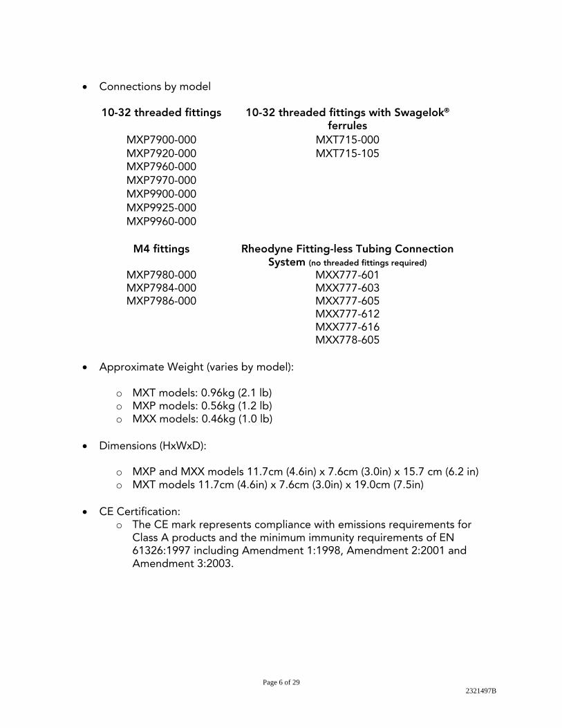
• Connections by model
10-32 threaded fittings 10-32 threaded fittings with Swagelok® ferrules
MXP7900-000 MXT715-000 MXP7920-000 MXT715-105 MXP7960-000 MXP7970-000 MXP9900-000 MXP9925-000 MXP9960-000
M4 fittings Rheodyne Fitting-less Tubing Connection
System (no threaded fittings required) MXP7980-000 MXX777-601 MXP7984-000 MXX777-603 MXP7986-000 MXX777-605
MXX777-612 MXX777-616 MXX778-605
• Approximate Weight (varies by model):
o MXT models: 0.96kg (2.1 lb) o MXP models: 0.56kg (1.2 lb) o MXX models: 0.46kg (1.0 lb)
• Dimensions (HxWxD):
o MXP and MXX models 11.7cm (4.6in) x 7.6cm (3.0in) x 15.7 cm (6.2 in) o MXT models 11.7cm (4.6in) x 7.6cm (3.0in) x 19.0cm (7.5in)
• CE Certification:
o The CE mark represents compliance with emissions requirements for Class A products and the minimum immunity requirements of EN 61326:1997 including Amendment 1:1998, Amendment 2:2001 and Amendment 3:2003.

Page 7 of 29 2321497B
Installation
Cautions • Use only contact closure, I2C, or USB for connections from your instrument or
computer to the MX Series II Module. • Do not supply more than 24 VDC to the MX Series II Module or it will be
damaged. • Rinse the valve after using buffer solutions to prevent the formation of crystals
that can scratch and damage the sealing surfaces. • Use only the supplied Universal Power Supply with the MX Series II Module. • Operate within a temperature range of 0-50°C only. • When controlling the unit via I2C or USB, make certain the unit is not set to
Level Logic control. Any other setting (BCD, Pulse logic, etc.) is acceptable.
Warnings • Do not submerge the MX Series II Module in liquids. • Confirm that there is adequate ground between your controlling instrument and
the MX Series II Module. This is especially important with electrospray mass spectroscopy.
• Plug the Universal Power Supply into the MX Series II Module first, and then plug the Universal Power Supply into an AC power source.
• When disconnecting, unplug at the AC power source first.
General Description The MX Series II Module is small and capable of both automated and manual control. Schematics of the available flow diagrams are shown on page 4. The flow paths shown are representations of the flow paths and may not show the true positions of the ports and grooves. The circles represent the ports in the valve stator. The grooves represent the connecting passages in the rotor seal. All electrical and communication connections to the MX Series II Modules are made at the rear on the device.

Page 8 of 29 2321497B
Electrical Connections • Plug the Universal Power Supply male barrel connector into the MX Module
female port.
• Plug the female connector of the Power Cord into the Universal Power Supply. • Plug the opposite end of the Power Cord into a properly grounded power
source. The Universal Power Supply can be operated from inputs of 100-240 VAC, 50-60Hz. The output is 24 VDC, 1.88A.
Communication Cable Connections To operate the MX Series II Module manually as a stand alone unit no additional connections are required, continue to page 11. There are several ways to automate control of the MX Series II Module.
• For two position modules only o Level Logic control via a single line of the supplied interface cable and
the contact closure terminal of a controlling instrument. • For all valves
o 4-Line Binary Coded Decimal (BCD), also using the supplied interface cable and contact closure terminals of a controlling device
o USB control via connection to a computer. o Additional methods of control are available. For more information about
control with Pulse logic, Dual-pulse, Inverted BCD, I2C, or USB please see the Driver/Controller Development Assistance Package for

Page 9 of 29 2321497B
Rheodyne MX II (2321500). For additional information on USB and I2C communications see documents 2321382 and 2321383 respectively.
Interface Cable Connection for Remote Operation via Instrument
• Connect the interface cable to the mating connector on the back of the MX Series II Module.
• Connect the interface cable wires to the controlling instrument contact closure
as instructed below. The controlling instrument must have one contact closure output (event relay) for two-position valves and four contact closure outputs for multi-position valves.
Two-position MX Series II Modules • Connect wire #1 of the interface cable from the MX Series II Module to the
ground terminal of the controlling instrument event relay 1 (GND). • Connect wire #6 from the MX Series II interface cable to the controlling
instrument event relay 1 (R1). • See the example on page 12 of generic time programming commands for this
type of control.
Fig 1. Wire connections for two-position MX Series II Modules. Wire colors will vary.
For Information on wiring to monitor feedback signals please see the Driver/Controller Development Assistance Package for Rheodyne MX II (2321500).
Multi-position MX Series II Modules • Connect the wire #1 of the interface cable from the MX Series II Module to the
ground terminal of the controlling instrument event relay 1 (GND). • Using the provided jumper wires, jumper the ground terminals of event relays 2
(R2), 3 (R3), and 4 (R4), as shown in figure 2.

Page 10 of 29 2321497B
• Connect wire #9 from the MX Series II interface cable to the controlling instrument event relay 1 (R1).
• Connect wire #8 from the interface cable to event relay 2 (R2). • Connect wire #7 from the interface cable to event relay 3 (R3). • Connect wire #6 from the interface cable to event relay 4 (R4).
Fig 2. Wire connections for multi-position MX Series II Modules. Wire colors will vary.
• See the example on page 13 of generic time programming commands for this
type of control.
For Information on wiring to monitor feedback signals please see the Driver/Controller Development Assistance Package for Rheodyne MX II (2321500).
Start Signal for Data Acquisition (For 2-Position Valves only) MX Series II 2-position modules have the capability to issue a signal to a chromatographic system for starting data acquisition. The start signal is sent exactly when the valve moves from the Load to Inject position for maximum accuracy of retention times. If your system requires a high to low transition (contact closure signal) to start data acquisition, simply connect the grey wire (pin 8) of the interface cable to the start-acquisition connector on your instrument. If instead your system requires a low to high transition, connect the black wire (pin 9) of the interface cable to the start-acquisition connector on your instrument.
Needle Port Installation for Syringe Loading Injectors For models MXP7920-000 and MXP9925-000, a needle port is included in the fittings so these may be used as syringe loading injectors. To install the needle port in model MXP7920-000, screw the nut into the vertical port. If the inner tube is not snug around your syringe needle, then tighten the fitting until it fits snugly. To install the needle port in the MXP9925-000, screw the provided needle port into the center port and adjust similarly.

Page 11 of 29 2321497B
Operation
Control Panel Overview The MX Series II Module control panel is shown in figure 3.
• (1) Remote Button • (2) Remote Indicator Light • (3) Manual Forward Position
Selector Button • (4) Manual Backward Position
Selector Button Figure 3 . MX Series II Control Panel
Local or Manual Operation • Put the MX Series II Module in the local mode by pushing the Remote Button.
Local Mode is indicated when the LED light next to the Remote Button is not illuminated.
• Use the Forward Position Selector Button to move the valve in the clockwise direction.
• Use the Backward Position Selector Button to move the valve in the counterclockwise direction.
Remote Operation from a Controlling Instrument 1. Input Line Control (controlling with a contact closure or event relays)
a) 1-line control (for models with two positions)- The instrument used to control these models must have one contact closure output . (1) When the logic state is changed to OPEN, (HIGH or OFF), the valve will
rotate to position 1. When the logic state is changed to CLOSED, (LOW, ON, or GROUND), the valve will rotate to position 2.
(2) Wire the interface cable to the instrument for 1 line control (see fig 1) (3) See page 12 for 1-line level logic generic time programming example.
(Note- the actual programming will vary depending on the manufacturer of the instrument used. Hookup documents for selected instruments are available at http://www.rheodyne.com/support/.)
1
2
3
4
Page 12 of 29 2321497B
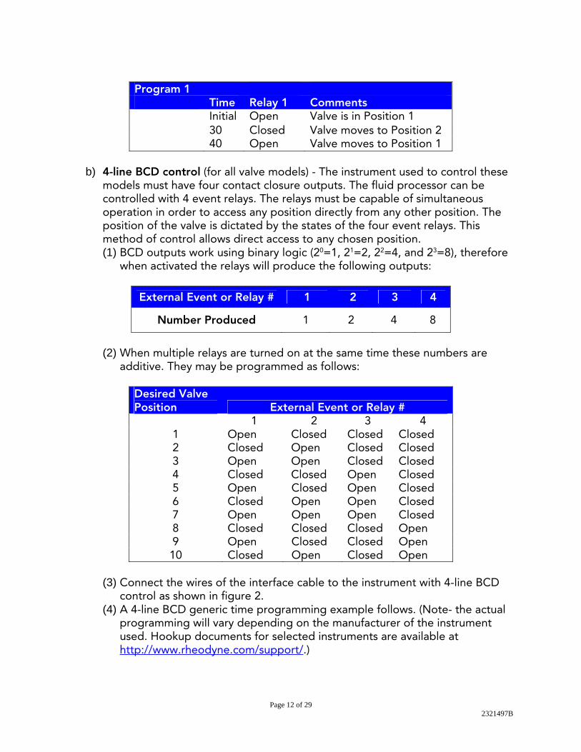
Program 1
Time Relay 1 Comments Initial Open Valve is in Position 1 30 Closed Valve moves to Position 2 40 Open Valve moves to Position 1
b) 4-line BCD control (for all valve models) - The instrument used to control these
models must have four contact closure outputs. The fluid processor can be controlled with 4 event relays. The relays must be capable of simultaneous operation in order to access any position directly from any other position. The position of the valve is dictated by the states of the four event relays. This method of control allows direct access to any chosen position. (1) BCD outputs work using binary logic (20=1, 21=2, 22=4, and 23=8), therefore
when activated the relays will produce the following outputs:
External Event or Relay # 1 2 3 4
Number Produced 1 2 4 8
(2) When multiple relays are turned on at the same time these numbers are
additive. They may be programmed as follows:
Desired Valve Position External Event or Relay # 1 2 3 4
1 Open Closed Closed Closed 2 Closed Open Closed Closed 3 Open Open Closed Closed 4 Closed Closed Open Closed 5 Open Closed Open Closed 6 Closed Open Open Closed 7 Open Open Open Closed 8 Closed Closed Closed Open 9 Open Closed Closed Open 10 Closed Open Closed Open
(3) Connect the wires of the interface cable to the instrument with 4-line BCD
control as shown in figure 2. (4) A 4-line BCD generic time programming example follows. (Note- the actual
programming will vary depending on the manufacturer of the instrument used. Hookup documents for selected instruments are available at http://www.rheodyne.com/support/.)

Page 13 of 29 2321497B
Remote Control from a Computer 1. USB Control with the
Included Rheodyne TitanMXtm Software a) Insert the enclosed CD
into your computer. Locate the setup.exe file and double click on it.
b) Follow the instructions on the screen.
c) Make sure to mark the checkbox to get a desktop icon.
d) Connect the power cord to the power supply and plug into an outlet.
e) When the installation is complete, connect the USB cable to the MX Series II Module and an available USB port on your computer. The remote LED should be lit.
f) Wait for the computer to find new hardware and tell you it is ready to use.
g) Double click on the Rheodyne TitanMXTM icon to launch the software.
Program 2
Time Relay 1 Relay 2 Relay 3 Relay 4 Comments Initial Closed Open Open Closed Valve is in Position 6 10 Open Closed Closed Closed Valve moves to Position 1 20 Closed Open Closed Closed Valve moves to Position 2 30 Open Open Closed Closed Valve moves to Position 3 40 Closed Closed Open Closed Valve moves to Position 4 50 Open Closed Open Closed Valve moves to Position 5 60 Closed Open Open Closed Valve moves to Position 6 70 Open Open Open Closed Valve moves to Position 7 80 Closed Closed Closed Open Valve moves to Position 8 90 Open Closed Closed Open Valve moves to Position 9
Page 14 of 29 2321497B
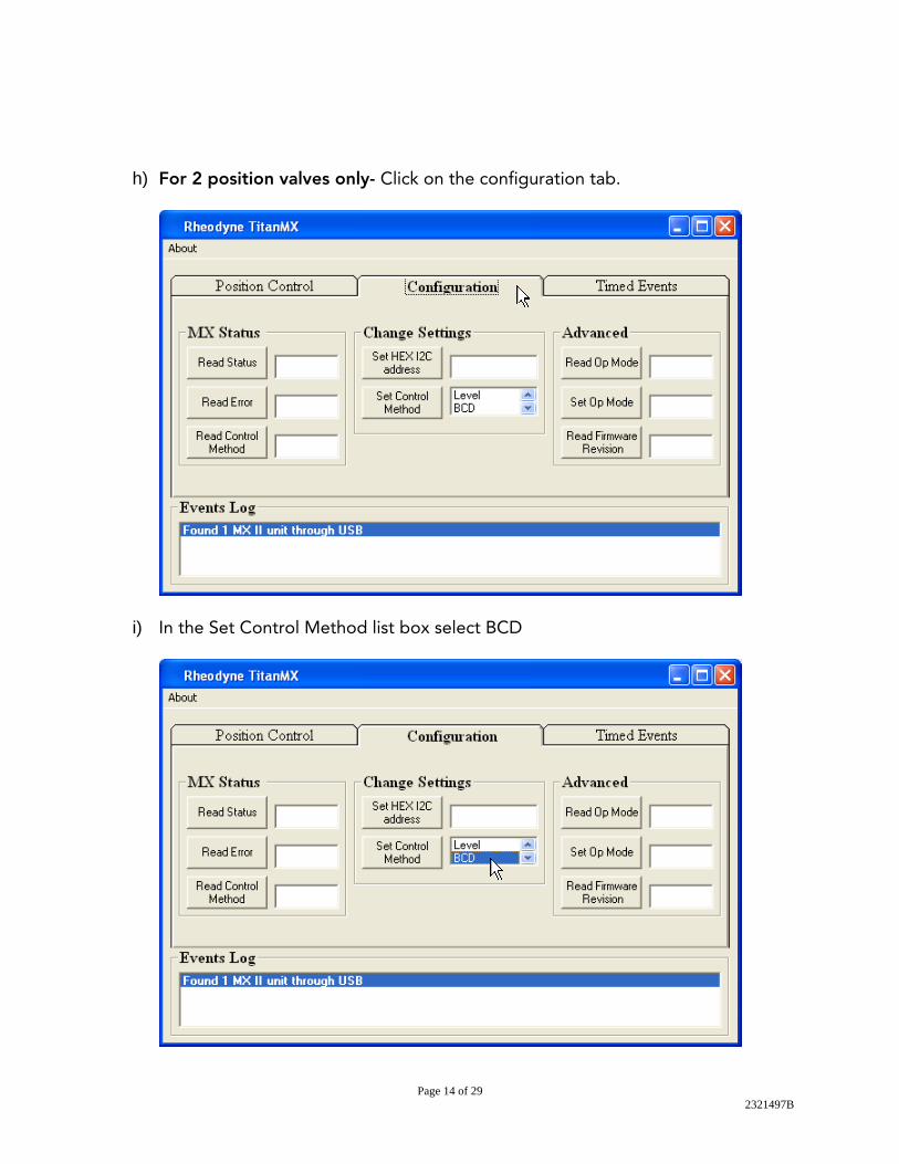
h) For 2 position valves only- Click on the configuration tab.
i) In the Set Control Method list box select BCD
Page 15 of 29 2321497B
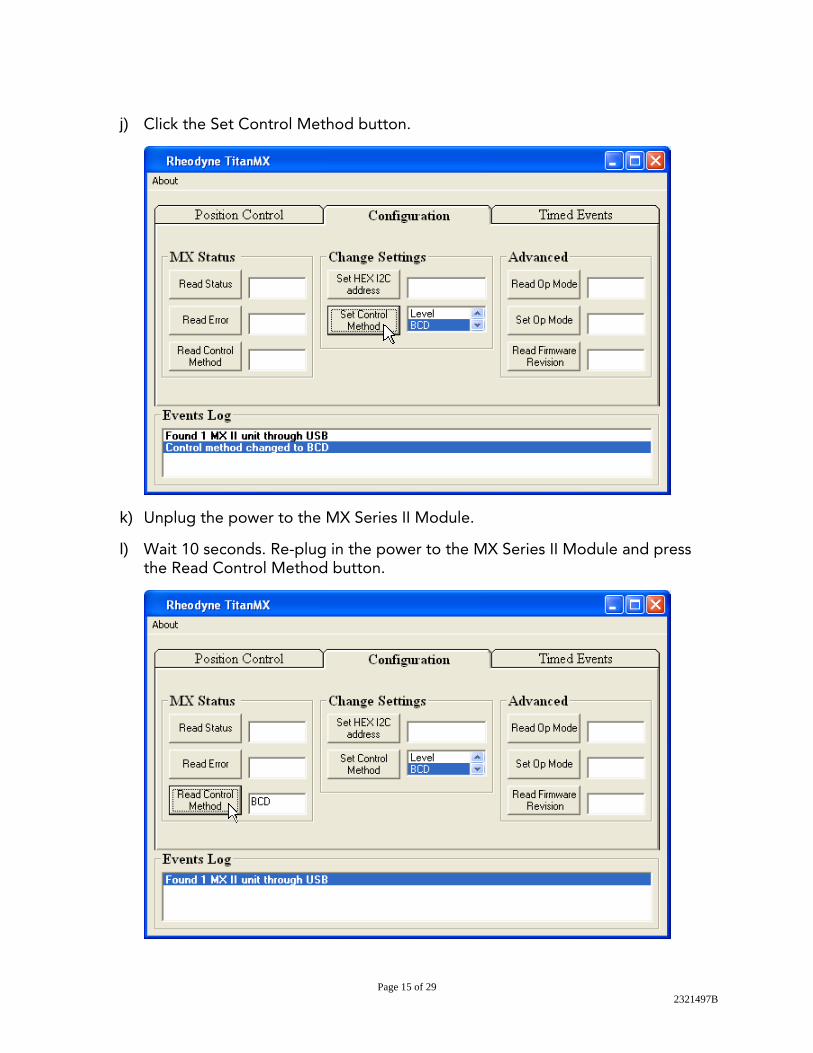
j) Click the Set Control Method button.
k) Unplug the power to the MX Series II Module.
l) Wait 10 seconds. Re-plug in the power to the MX Series II Module and press the Read Control Method button.

Page 16 of 29 2321497B
m) If it does not return BCD in the box next to the button repeat steps g-l. n) For all valves- Click the Position Control tab.
You may now use the mouse to click the position buttons to change the position of your valve.
Note- the valve will not respond to positions unavailable on your model.

Page 17 of 29 2321497B
2. Using the Timed Events Table (This mode of control should not be used when the
MX Series II module is being controlled by another instrument. In that case use the timed events table from the controlling instrument.) a) Click on the Timed Events Tab.
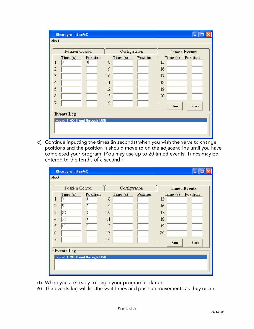
b) If you wish to set the starting position of the valve enter 0 (zero) in the first time field. Enter the position you wish the valve set to in the adjacent position field.
Page 18 of 29 2321497B
c) Continue inputting the times (in seconds) when you wish the valve to change
positions and the position it should move to on the adjacent line until you have completed your program. (You may use up to 20 timed events. Times may be entered to the tenths of a second.)
d) When you are ready to begin your program click run. e) The events log will list the wait times and position movements as they occur.

Page 19 of 29 2321497B
f) Please note that the events must be listed in chronological order or an error will
occur and the program will terminate at the point of the error. g) If an invalid position is requested this will also result in an error which will stop
the program at that point. h) The program may be stopped at any time by clicking stop. Please note that if a
run is stopped and start is pressed again the program will restart at the beginning.
i) The events table cannot be saved. It will clear if the interface is closed.

Page 20 of 29 2321497B
Maintenance
Electrical Maintenance • If an electrical problem is encountered, please consult Electrical Connections on
page 8 and Troubleshooting on pages 21-25. If the problem persists contact your vendor for assistance.
• No routine maintenance is required for the electronic components.
Valve Maintenance With normal use the MX Series II Module will provide tens of thousands of cycles. The main cause of failure, which results in valve leakage, is often abrasive particles in the sample and/or mobile phase or crystallization of buffer solutions. This can cause scratches on the rotor seal, stator face seal, or stator. MXT and MXP models may be repaired by Pod replacement or replacement of the rotor seal (and stator face seal for some models) and/or stator. For long life MXX models the rotor seal and stator are not end-user serviceable. Rapid Replacement Pods, Stators, and RheBuild® kits (for replacement seals) are available from your vendor for your repair needs. For more information on our maintenance options, visit our website at http://www.rheodyne.com/.
Rotor Seal Replacement (This may be done on the MX Series II Module directly or on the Rapid Replacement Pod.)
• Remove the Stator Screws from the Stator with the Hex key provided. Loosen the screws sequentially a quarter turn at a time to avoid damaging the srews.
• Remove the Stator (and the stator face seal if present) from the valve/pod body. • Remove the Rotor Seal; you may use a flat head screwdriver to pry it up if
needed. • Remove the Stator Face Seal from the Stator (if present). • Mount the new Stator Face Seal (if present) on the Stator. The three pins on the
Stator Face Seal fit into the Stator in only one way. • Mount the new Rotor Seal with the grooves facing out toward the Stator. The
three pins in the shaft assembly fit into the mating holes in the Rotor Seal only one way.
• Mount the Stator on the Pod Assembly so that the stator locating pins in the body enter the mating holes on the Stator.
• Replace the three Stator Screws. Tighten each down firmly a quarter turn at a time sequentially until the stator is flush against the stator ring.

Page 21 of 29 2321497B
Rapid Replacement Pod *Please note that MXP and MXT Pods are not interchangeable.
• Disconnect all tubing and sample loops prior to Rapid Replacement Pod removal.
For MXP Models: • Insert the Pod PopperTM tab in any of the Rapid Replacement Pod slots.
• Turn the Spanner nut counter clockwise until the Rapid Replacement Pod detaches from the MX Series II Module. (Do not use wrenches on the Spanner nut.)
• Remove the Pod Popper and Spanner nut from the Rapid Replacement Pod. • Take the Rapid Replacement Pod and insert it into the MX Series II Module,
rotate until the unions at the base of the Rapid Replacement Pod and the valve actuator engage.
• Continue to rotate until the 3 grooves in the Rapid Replacement Pod align with the three ribs on the housing and press the Rapid Replacement Pod into the actuator.
• Replace the spanner and tighten clockwise, (Hand tighten only, do not use
wrenches on the spanner nut.)
Spanner nut
Ribs
groove

Page 22 of 29 2321497B
For MXT Models: • Turn the Spanner nut counterclockwise to remove. • Gently pull the Rapid Replacement Pod from the MX Series II Module. • Take the Rapid Replacement Pod and insert into the MX Series II Module,
rotate until the unions within the actuator and the Rapid Replacement Pod engage.
• Continue to rotate until the clocking pin aligns with the notch in the housing.
• Press the Rapid Replacement Pod into the box. • Replace the Spanner nut and tighten clockwise, (Hand tighten only, do not use
wrenches on the Spanner nut.)

Page 23 of 29 2321497B
Definitions Contact Closure Also known as open collector or relay. It simply means there is no connection when the circuit is open. The line is either grounded (CLOSED) or not (OPEN). Event Relay See External Event Relay External Event Relay These are the terminals on the controlling instrument where the MX Series II Module is connected using the interface cable. They are also known as Timed Event Terminals, External Event Terminals, or Time Function Switches. Each relay has two terminals. When the relay is a contact closure one terminal is ground, the other is the control line. When a relay is TTL, one terminal is ground, the other is HI/LO (+5 volts/0 volts). Ground Common reference point required between two or more devices. Input This is the electrical communication coming into a device. For example, the MX Module requires either a TTL or contact closure signal. Level Logic This is a type of electrical signal. In reference to the MX Module, any change in the control signal's logic state will cause the valve to move one position.
Line Control This is a remote control scheme employing separate wires. Each wire is used with a common ground to send signals controlling a device. Logic State The terminal at the event relay is in either one or the other state in the following pairs, HI/LO, OPEN/CLOSED, ON/OFF, OPEN/GROUND. For example, in a contact closure switch the relay is either grounded (GROUND) or not (OPEN). MBB (Make-Before-Break) A passage in the stator, or stator face assembly, that allows new connections to be made before old connections are broken when switching from load to inject. This virtually eliminates pressure transients, a benefit with fragile columns or flow sensitive detectors. Output This is the electrical communication coming out of a device. For example, the MX Module has two output lines which are provided via the terminal block. Pin number 5 of the terminal block is the Busy/Done feedback (LO = busy, HI = done) and Pin number 6 is the Error feedback (LO = error detected, HI = no error detected). State See Logic State. Terminal The position at the event relay where the wire is connected. Each event relay has two terminals.

Page 24 of 29 2321497B
TTL Abbreviation for Transistor-Transistor-Logic, also called digital logic. A control line is either HI (+5 volts) or LO(0 volts). Typical OFF state of an instrument's TTL switch is HI.
Universal Power Supply This is the adapter that converts electrical power from a wall socket to usable power to run the MX Series II Module. The input required is 100-240 VAC, 50-60 Hz. The output of the power supply is 24 VDC.

Page 25 of 29 2321497B
Troubleshooting
Symptom Cause Solution 1. Valve leaks between the Stator and Stator Ring or from a port
A: The Rotor Seal and/or Stator Face Seal may have been damaged by abrasive particles in the sample and/or mobile phase or crystallization of buffer solutions.
Replace the Rotor Seal and Stator Face Seal using the MX Series II Module RheBuild® Kit available from your vendor. Filter sample and mobile phase. Flush the valve frequently to prevent crystallization of buffer solutions.
B: The pressure rating of the valve has been exceeded.
Confirm that the pressure increase is not caused by a blockage in the flow path. If no blockage, lower the flow rate or change the post MX Module tubing to decrease the pressure.
C: The stator port is damaged and a fitting does not seal correctly.
Replace the Stator.
2. Valve is not rotating.
A: There is no power to the MX Series II Module.
Confirm there is power at the source and all electrical connections are secure.
B: The program and/or wiring to control the MX Series II Module is incorrect.
Check the program used to control the MX Series II Module. Review the wiring on pages 9-10.
C: Nothing happens when pressing the Forward Position Selector button while attempting to change the valve position.
Set the control mode to local (manual) mode. Push the Remote button. The LED should be off.
D: Attempting to rotate the valve using the Remote (automated) control mode (with either TTL or contact closure).
Verify that you have programmed the computer or instrument control software correctly and that the device is outputting a correct output (either TTL or contact closure).
F: Additional problems.
See Troubleshooting Flow Charts on pages 24-26.
Page 26 of 29 2321497B
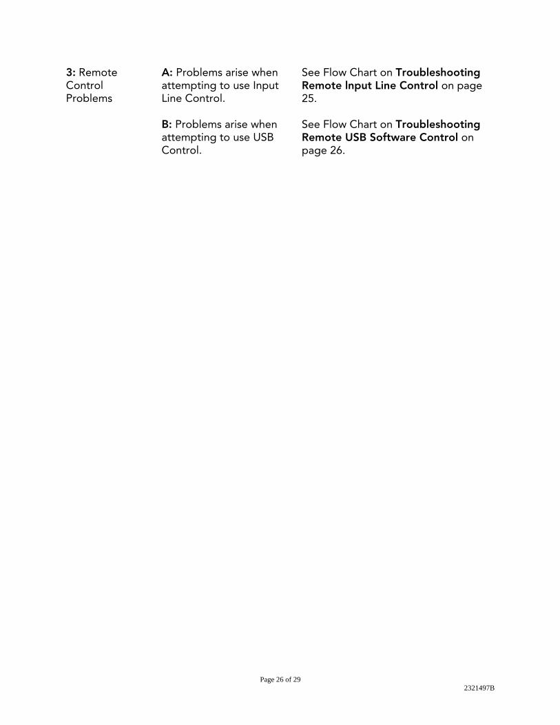
3: Remote Control Problems
A: Problems arise when attempting to use Input Line Control.
See Flow Chart on Troubleshooting Remote lnput Line Control on page 25.
B: Problems arise when attempting to use USB Control.
See Flow Chart on Troubleshooting Remote USB Software Control on page 26.
Page 27 of 29 2321497B
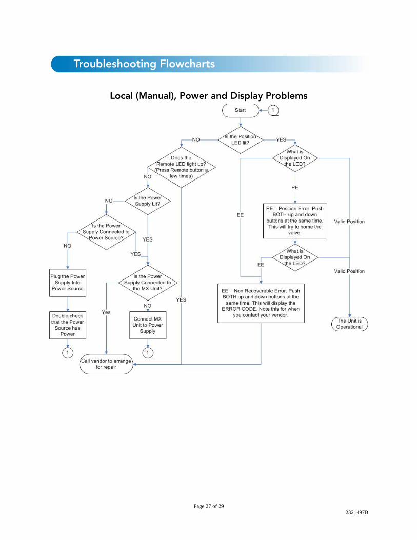
Troubleshooting Flowcharts
Local (Manual), Power and Display Problems

Page 28 of 29 2321497B
Remote (Automatic), Input Line Control Problems

Page 29 of 29 2321497B
Remote (Automatic), USB Software Control Problems