Embed Size (px)
Citation preview

Research ArticleMuscle Coordination Control for an Asymmetrically Antagonistic-Driven Musculoskeletal Robot Using Attractor Selection
Shoichiro Ide1 and Atsushi Nishikawa 2,3
1Interdisciplinary Graduate School of Science and Technology, Shinshu University, Ueda 386-8567, Japan2Faculty of Textile Science and Technology, Shinshu University, Ueda 386-8567, Japan3Division of Biological and Medical Fibers, Institute for Fiber Engineering (IFES), Interdisciplinary Cluster for Cutting EdgeResearch (ICCER), Shinshu University, Ueda 386-8567, Japan
Correspondence should be addressed to Atsushi Nishikawa; [email protected]
Received 31 March 2018; Revised 21 June 2018; Accepted 5 July 2018; Published 12 September 2018
Academic Editor: Dongming Gan
Copyright © 2018 Shoichiro Ide and Atsushi Nishikawa. This is an open access article distributed under the Creative CommonsAttribution License, which permits unrestricted use, distribution, and reproduction in any medium, provided the original workis properly cited.
Recently, numerous musculoskeletal robots have been developed to realize the flexibility and dexterity analogous to human beingsand animals. However, because the arrangement of many actuators is complex, the design of the control system for the robot isdifficult and challenging. We believe that control methods inspired by living things are important in the development of thecontrol systems for musculoskeletal robots. In this study, we propose a muscle coordination control method using attractorselection, a biologically inspired search method, for an antagonistic-driven musculoskeletal robot in which various muscles(monoarticular muscles and a polyarticular muscle) are arranged asymmetrically. First, muscle coordination control models forthe musculoskeletal robot are built using virtual antagonistic muscle structures with a virtually symmetric muscle arrangement.Next, the attractor selection is applied to the control model and subsequently applied to the previous control model withoutmuscle coordination to compare the control model’s performance. Finally, position control experiments are conducted, and theeffectiveness of the proposed muscle coordination control and the virtual antagonistic muscle structure is evaluated.
1. Introduction
Human beings and animals move flexibly and dexterously bycontrolling their musculoskeletal system with the brain. Tounderstand and imitate the flexible and dexterous motionof human beings and animals, several musculoskeletal robotshave recently been developed. The primary driving mecha-nism in musculoskeletal robots is a tendon-driven assemblyusing motors [1, 2] or pneumatic artificial muscles (PAMs).In particular, using PAMs as actuators enables flexible move-ment of the musculoskeletal robot compared with conven-tional robots that use motors because the compressibilityand low viscosity of air provide compliance and rapid con-traction. The extremely high power-to-weight ratio of thePAM is also good for flexible and dynamic motion.
The musculoskeletal robot comprises antagonistic-driven systems. An antagonistic-driven system includes twoor more actuators for joint movement. The actuators are
antagonistically arranged around one link, and their out-put characteristics and arrangements are, for the mostpart, symmetrical.
Many studies have proposed the musculoskeletal robotscomprising this simple antagonistic system, and various con-trol methods (e.g., PID control, neural network, and fuzzylogic) have also been proposed for musculoskeletal robots[3–8]. However, the drive system of our musculoskeletalrobot [9] differs from a simple antagonistic-driven systembecause the output characteristics and the arrangements ofthe actuators of the robot are not symmetrical.
This robot has two kinds of PAM actuators, a monoarti-cular muscle that drives one joint and a polyarticular musclethat drives multiple joints consecutively. Therefore, themechanism that drives each joint is not symmetrical. Fur-thermore, the actuators are not arranged symmetrically,although each actuator is antagonistically arranged aroundeach link. Since each actuator is not arranged symmetrically
HindawiApplied Bionics and BiomechanicsVolume 2018, Article ID 9737418, 10 pageshttps://doi.org/10.1155/2018/9737418
and the sensors for measuring each joint angle are notarranged, design of the control system for the robot is moredifficult and challenging.
Honda et al. [9, 10] proposed a biologically inspired con-trol method using muscle coordination for the robot. Theyhypothesized that human beings use the synergies betweenantagonistic muscle pairs when joints move, and they definedtwo parameters, the antagonistic muscle ratio and the antag-onistic muscle activity, as the key parameters in human mus-cle coordination. The parameters are computed by a PIDcontroller [10] and are implemented to control the angle ofthe robot’s joints.
Although good control performance was obtained forone joint, the controller did not work well for multiple jointsof the robot [9]. An adaptive method that dynamically andadaptively searches the parameters for muscle coordinationwas required because PAMs have time variance, compliance,high hysteresis, and nonlinearity. In general, this searchproblem can be formulated as a combinatorial optimizationproblem of minimizing an object function subject to thesearch variables, which requires a precise model (objectfunction) in advance, but system identification against anasymmetrically antagonistic-driven PAM system havingnonlinear dynamics is difficult.
As an alternative to such a model-based theoreticalapproach, we believe that heuristic control methodsinspired from living things are important for the controlof the musculoskeletal robot. The musculoskeletal struc-tures of human beings and animals are antagonistic-drivensystems. They are also asymmetrically antagonistic-drivensystems because monoarticular muscles and polyarticularmuscles are arranged around various joints. Human beingsand animals move flexibly by controlling their variousmuscles dexterously.
Recent research about the mechanisms of living thingsindicates that a biological system behaves flexibly using noise[11]. Escherichia coli (E. coli) cells usually prefer to switch toan adaptive attractor using noise to survive better in a newexternal environment after the environmental conditionshave been changed. This adaptive behavior of the E. coli cellsis known as attractor selection [12]. The novel controlmethod based on the attractor selection has been proposedand applied to a signal-control method for traffic networks[13], network management [14, 15], android motion genera-tion [16], robot navigation and locomotion [17–19], roboticarm control [20–22], and endoscopic surgery [23].
The control method was described by a stochastic differ-ential equation, input variables for the network systems orrobots were computed by solving the equation, and the sys-tems accomplished the tasks without the dynamics andmodel of the systems and environments. Since the attractorselection is conducted adaptively using noise in the systemsor environments, the control method is robust for changesof tasks and environments. Attractor selection was appliedto an asymmetrically antagonistic-driven musculoskeletalrobot (Figure 1) with muscles arranged asymmetrically[24]. From the control experiment, the position of the tip ofthe robot was moved to the desired position by searchingpressure for four PAMs individually using the attractor
selection. The control time had to be more than 100 s toaccomplish tasks. Therefore, modification of the controlmethod is required to accomplish tasks quickly.
In this study, we propose a novel muscle coordinationcontrol method for the asymmetrically antagonistic-drivenmusculoskeletal robot using the attractor selection. The pri-mary difference between the previous method [24] and theproposed one is that the proposed method introduced a vir-tual antagonistic muscle structure as a muscle coordinationcontrol model. Instead of individually and directly searchingthe PAM pressure in the actual asymmetric antagonisticmuscle structure, the new method indirectly searches pres-sure for actual PAMs via a virtual symmetric antagonisticmuscle structure.
First, muscle coordination control models of the mus-culoskeletal robot were built using virtual antagonistic mus-cle structures with a virtually symmetric arrangement ofmuscles. Next, the attractor selection was applied to thecontrol model and also applied to the previous controlmodel without the muscle coordination to compare controlperformance. Finally, position control experiments were con-ducted, and the effectiveness of the proposed muscle coordi-nation control applied attractor selection and the virtualantagonistic muscle structure was evaluated.
2. Materials and Methods
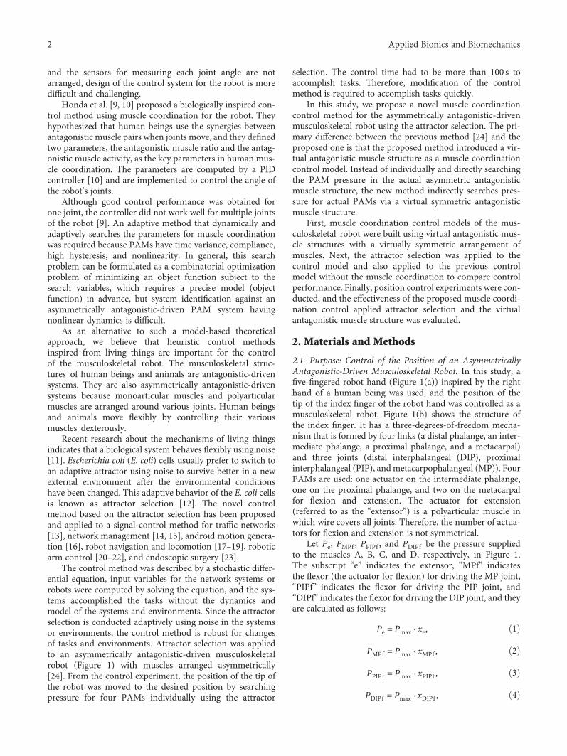
2.1. Purpose: Control of the Position of an AsymmetricallyAntagonistic-Driven Musculoskeletal Robot. In this study, afive-fingered robot hand (Figure 1(a)) inspired by the righthand of a human being was used, and the position of thetip of the index finger of the robot hand was controlled as amusculoskeletal robot. Figure 1(b) shows the structure ofthe index finger. It has a three-degrees-of-freedom mecha-nism that is formed by four links (a distal phalange, an inter-mediate phalange, a proximal phalange, and a metacarpal)and three joints (distal interphalangeal (DIP), proximalinterphalangeal (PIP), andmetacarpophalangeal (MP)). FourPAMs are used: one actuator on the intermediate phalange,one on the proximal phalange, and two on the metacarpalfor flexion and extension. The actuator for extension(referred to as the “extensor”) is a polyarticular muscle inwhich wire covers all joints. Therefore, the number of actua-tors for flexion and extension is not symmetrical.
Let Pe, PMPf , PPIPf , and PDIPf be the pressure suppliedto the muscles A, B, C, and D, respectively, in Figure 1.The subscript “e” indicates the extensor, “MPf” indicatesthe flexor (the actuator for flexion) for driving the MP joint,“PIPf” indicates the flexor for driving the PIP joint, and“DIPf” indicates the flexor for driving the DIP joint, and theyare calculated as follows:
Pe = Pmax · xe, 1
PMPf = Pmax · xMPf , 2
PPIPf = Pmax · xPIPf , 3
PDIPf = Pmax · xDIPf , 4
2 Applied Bionics and Biomechanics
where xe ∈ 0, 1 , xMPf ∈ 0, 1 , xPIPf ∈ 0, 1 , and xDIPf∈ 0, 1 are the normalized search variables and Pmax is
the maximum pressure supplied to the actuator. Since theactuators of the robot hand break if a pressure of more than0.2MPa is supplied, the value of Pmax is set to 0.19MPa.
2.2. Muscle Coordination Hypothesis. Honda et al. suggestedthe hypothesis that muscle coordination of human beings isa coordination of antagonistic muscles (the extensor andflexor) [9, 10]. They express the ratio of the coordinationusing two parameters, the antagonistic muscle ratio (Ar)and antagonistic muscle activity (Ac). The Ar is the valuethat regulates the ratio of pressure (Pe and P f ) betweenthe antagonistic muscle e (the extensor) and f (the flexor).Ar is calculated between 0 and 1 and is defined as follows:
Ar = PePe + P f
5
Ac is the sum of pressure for the extensor e and the flexorf and is calculated by
Ac = Pe + P f 6
In this study, Ac is always set to the maximum pressurefor driving joints sufficiently. That is,
Ac = Pmax 7
Pressures Pe and P f are calculated from (5), (6), and (7).
Pe = Pmax · Ar, 8
P f = Pmax · 1 −Ar 9
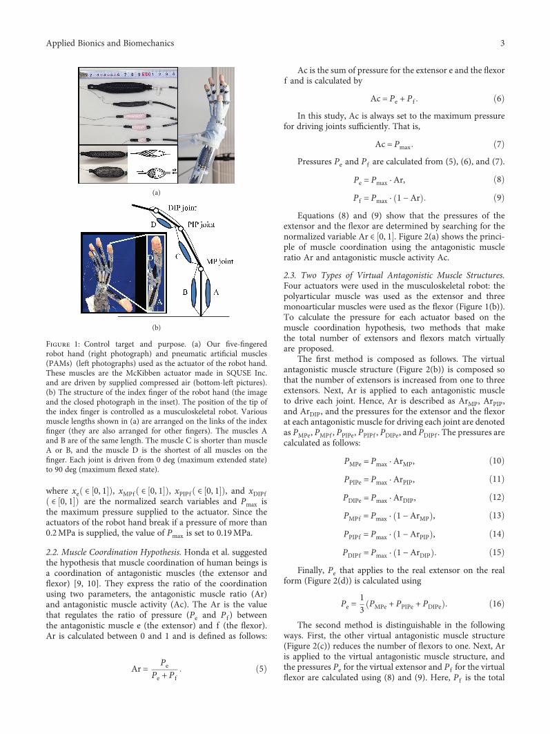
Equations (8) and (9) show that the pressures of theextensor and the flexor are determined by searching for thenormalized variable Ar ∈ 0, 1 . Figure 2(a) shows the princi-ple of muscle coordination using the antagonistic muscleratio Ar and antagonistic muscle activity Ac.
2.3. Two Types of Virtual Antagonistic Muscle Structures.Four actuators were used in the musculoskeletal robot: thepolyarticular muscle was used as the extensor and threemonoarticular muscles were used as the flexor (Figure 1(b)).To calculate the pressure for each actuator based on themuscle coordination hypothesis, two methods that makethe total number of extensors and flexors match virtuallyare proposed.
The first method is composed as follows. The virtualantagonistic muscle structure (Figure 2(b)) is composed sothat the number of extensors is increased from one to threeextensors. Next, Ar is applied to each antagonistic muscleto drive each joint. Hence, Ar is described as ArMP, ArPIP,and ArDIP, and the pressures for the extensor and the flexorat each antagonistic muscle for driving each joint are denotedas PMPe, PMPf , PPIPe, PPIPf , PDIPe, and PDIPf . The pressures arecalculated as follows:
PMPe = Pmax · ArMP, 10
PPIPe = Pmax · ArPIP, 11
PDIPe = Pmax · ArDIP, 12
PMPf = Pmax · 1 −ArMP , 13
PPIPf = Pmax · 1 −ArPIP , 14
PDIPf = Pmax · 1 −ArDIP 15
Finally, Pe that applies to the real extensor on the realform (Figure 2(d)) is calculated using
Pe =13 PMPe + PPIPe + PDIPe 16
The second method is distinguishable in the followingways. First, the other virtual antagonistic muscle structure(Figure 2(c)) reduces the number of flexors to one. Next, Aris applied to the virtual antagonistic muscle structure, andthe pressures Pe for the virtual extensor and P f for the virtualflexor are calculated using (8) and (9). Here, P f is the total
(a)
(b)
Figure 1: Control target and purpose. (a) Our five-fingeredrobot hand (right photograph) and pneumatic artificial muscles(PAMs) (left photographs) used as the actuator of the robot hand.These muscles are the McKibben actuator made in SQUSE Inc.and are driven by supplied compressed air (bottom-left pictures).(b) The structure of the index finger of the robot hand (the imageand the closed photograph in the inset). The position of the tip ofthe index finger is controlled as a musculoskeletal robot. Variousmuscle lengths shown in (a) are arranged on the links of the indexfinger (they are also arranged for other fingers). The muscles Aand B are of the same length. The muscle C is shorter than muscleA or B, and the muscle D is the shortest of all muscles on thefinger. Each joint is driven from 0 deg (maximum extended state)to 90 deg (maximum flexed state).
3Applied Bionics and Biomechanics
pressure for the three real flexors (PMPf , PPIPf , and PDIPf ) andis defined as P f ≤ Pmax. Finally, P f is distributed to the threereal flexors on the real form (Figure 2(d)). Two distributionratios (DrMP and DrPIP) are used, and the pressure for thethree real flexors is calculated by
PMPf = P f · DrMP, 17
PPIPf = P f − PMPf · DrPIP, 18
PDIPf = P f − PMPf + PPIPf 19
Pressure for the real extensor is the same as that for thevirtual extensor and is calculated using (8).
2.4. Attractor Selection Model. Let us consider the combi-natorial optimization problem of minimizing an objectfunction U x subject to the search variable x ∈ X1, X2,… ,XN , where Xi is a feasible solution (an attractor) and Nmeans the number of attractors. Rather than seek an opti-mal solution, we try to quickly find good approximatesolutions. To accomplish this, our study uses the revisedattractor selection model, which has been generalized asa stochastic differential equation [24]:
ddt
x t = f x t · Activity t + 1 −Activity t · η t ,
20
where t is time, x is the search variable or state ( ∈ 0, 1 forour case), the value Activity ∈ 0, 1 is the degree of accom-plishment of the task, η is assumed as noise, and f x is thefunction that makes x converge to a suitable attractor. Typi-cally, the function f can be represented as f x = −∂U x /∂xif the objective function U x is known precisely in advance.
This model searches for a solution (the attractor) thatsuccessfully accomplishes the task using noise, and the Activity makes the behavior of the total system change. Noticethat as Activity increases, the term f x · Activity becomesmore dominant in (20) and the state transition becomesmore deterministic. Consequently, state x tends to beentrained into a suitable attractor, where it remains despitethe persistent noise. By contrast, decreasing the Activityincreases the dominance of the noise η, thereby flatteningthe potential landscape. In this scenario, the transitionbecomes more probabilistic, like a random walk, and x isdriven away from the attractor.
The function f x can be designed freely, even if theobjective function U x is unknown or not preciselydescribed. Two elements are required. The value of x mustconverge to the attractors, and the xmust remain at a suitableattractor. To satisfy these elements, f x is defined as follows:
f x ≡ 〠N−1
i=0
k2dXi − x 2 + k2w
⋅Xi − xXi − x
, 21
where Xi is the ith attractor, N is the number of attractors, kdis the power that attracts x, and kw is the range in which theattractor’s power kd is effective.
2.5. Employing the Attractor Selection to Determine thePressure Supplied to Each Actuator. The selection of theattractor is employed to determine the pressure supplied toeach actuator. The three methods used to determine the pres-sure using attractor selection are presented as follows.
The first method uses the real musculoskeletal structure(Figure 2(d)) and directly calculates the four pressures bysearching for the four variables (xe, xMPf , xPIPf , and xDIPf )using the attractor selection. We refer to this as a pressuresearch-type controller. The pressure supplied to each actua-tor is calculated by (1), (2), (3), and (4). This method is thesame as reported in our previous method in [24].
The second method uses the first virtual antagonisticmuscle structure (Figure 2(b)). It searches for the three ratios(ArMP, ArPIP, and ArDIP) using the attractor selection andsupplies the pressure to each actuator using (10), (11), (12),(13), (14), (15), and (16). We refer to this as an Ar search-type controller.
The third method uses the second virtual antagonisticmuscle structure (Figure 2(c)). It searches for the Ar valueand the two distribution ratios (DrMP and DrPIP) using theattractor selection and then supplies the pressure to eachactuator using (8), (9), (17), (18), and (19). This is referredto as an Ar and Dr search-type controller.
Figure 2: Muscle coordination and two types of virtual antagonisticmuscle structures. (a) Principle of the muscle coordination using theantagonistic muscle ratio Ar and the antagonistic muscle activityAc. When Ar is 0 (left picture), the pressure for the flexor is high(P f = Ac) and the extensor is low (Pe = 0). When Ar is 0.5 (middlepicture), the pressure for the flexor and the extensor is identical(P f = Pe = Ac/2). When Ar is 1 (right picture), the pressure for theflexor is low (P f = 0) and the extensor is high (Pe = Ac). Therefore,the pressures of the extensor and the flexor are determined bysearching for the normalized variable Ar ∈ 0, 1 . (b) One of thevirtual antagonistic structures. Two muscles are added virtually tothe musculoskeletal system (shown in (d)) to form a symmetricallyantagonistic arrangement on the intermediate phalange and theproximal phalange. Therefore, the virtual antagonistic structure hasthree simple antagonistic muscle structures (inset picture in (b)). (c)The other virtual antagonistic muscle structure. Two muscles on theintermediate phalange and the proximal phalange are decreasedvirtually from the musculoskeletal robot (shown in (d)), and themuscles are symmetrically arranged on the metacarpal. Therefore,the virtual antagonistic structure has one simple antagonisticmuscle structure (inset picture in (c)). (d) The real form of themusculoskeletal robot that is controlled. The value of Ar (shown in(a)) is applied to the virtual antagonistic structure (shown in (b)or (c)) virtually transformed from the musculoskeletal robot (shownin (d)).
4 Applied Bionics and Biomechanics

Notice that the search space for all the variables (xe, xMPf ,xPIPf , and xDIPf ; ArMP, ArPIP, and ArDIP; and Ar, DrMP, andDrPIP) ranges from 0 to 1.
3. Experimental Procedures
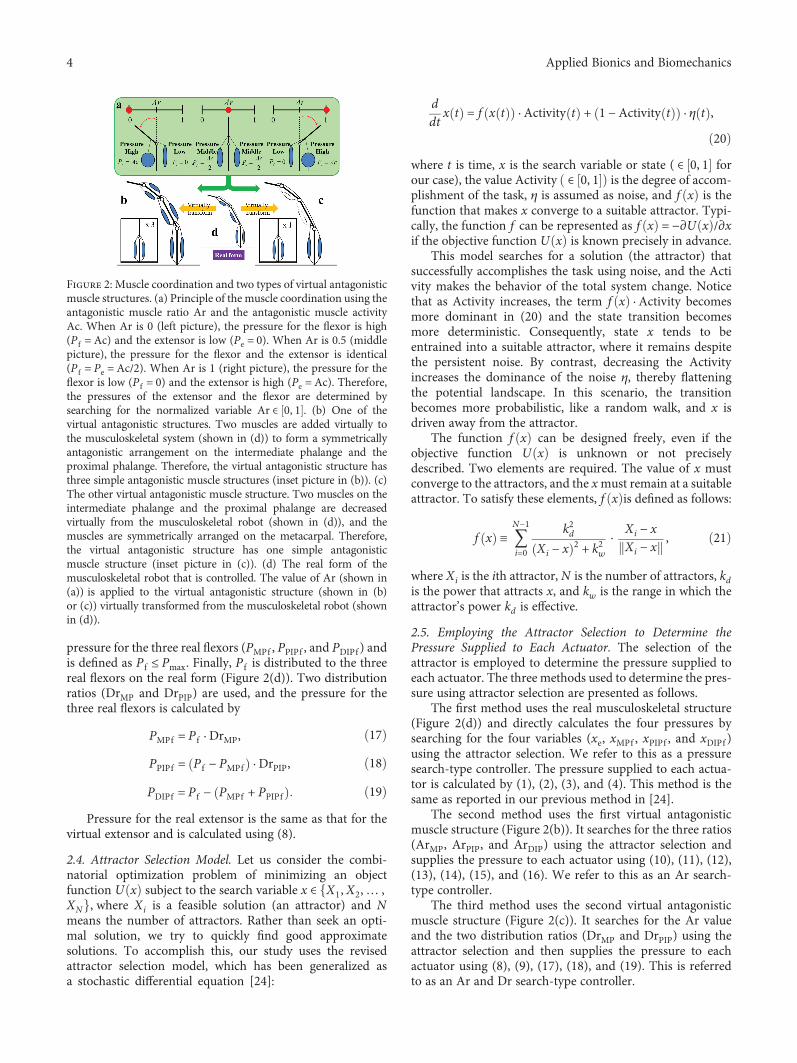
A control experiment that makes the tip of the index fin-ger of the musculoskeletal robot (see the bottom-rightinset in Figure 3) move to the desired position was con-ducted using the above three controllers. Figure 3 depictsthe experiment setup, which comprises the musculoskeletalrobot (SQUSE hand G type, SQUSE Inc.), the control PC(MDV ADVANCE ST 6300B (MouseComputer Co. Ltd.),Windows XP, and an Intel Core i7 920 (2.67GHz)), an A/Dconverter (AI-1664L-LPE, CONTEC Co. Ltd.), two D/A con-verters (AO-1616L-LPE, CONTEC Co. Ltd.), a digital outputboard (RRY-32-PE, CONTEC Co. Ltd.), a motion capturesystem (Nobby Tech. Ltd.), regulators (ITV0030, SMCCorporation), solenoid valves (S070-5DCO-32, SMC Cor-poration), and an air compressor (DPP-AYAD, KoganeiCorporation). The sampling frequency was set at 100Hz.The input signals were voltages generated by the control PCand were converted to pressures by the regulators. The out-put signals were the coordinates of the tip position [EX , EY ,EZ] sensed by the motion capture system. The Euclideannorm (the distance between the desired position [EXd , EYd ,EZd] and the tip position) was used as the evaluation indexof the controller. The Euclidean norm is described by l andcomputed using
l = EXd − EX2 + EYd − EY
2 + EZd − EZ2 22
AndActivity of the attractor selection model is calculatedfrom 0 to 1 using
Activity = −l
lmax+ 1 23
Here, lmax is the maximum value of a norm computedfrom the desired position and the tip position on either themaximum flexion, which is a steady state in which maximumpressure (0.19MPa) is supplied to all flexors, or the maxi-mum extension, which is a steady state in which maximumpressure is supplied to only the extensor of the robot.
Each norm was obtained in advance, and the largernorm was selected as lmax. Two tasks were conducted inthe experiment. The flexion task involved making the robotflex to a desired position from an extended state, the exten-sion task involved extending the robot to a desired positionfrom a flexed state, and the tasks were changed after a con-stant time. First, the flexion task was conducted. After aconstant time, the desired position was changed and theextension task was conducted. The control time was set at60 s, and the task was changed 30 s after the control wasstarted. The first position and the desired position weredefined when the robot was in a steady state after constantpressure was applied to each actuator. Each position wascaptured in advance.
In this experiment, the pressure value, represented byPe, PMPf , PPIPf , and PDIPf (0.05, 0.15, 0.05, and 0.05, resp.),was applied to each actuator to determine the desiredposition for the flexion task, and 0.15, 0.05, 0.05, and0.05, respectively, were applied to each actuator to deter-mine the desired position for the extension task. The ini-tial values of xe, xMPf , xPIPf , and xDIPf ; ArMP, ArPIP, andArDIP; and Ar, DrMP, and DrPIP were set to 0.9, 0.1, 0.1, and0.1; 0.9, 1.0, and 0.0; and 0.9, 1.0, and 0.0, respectively, andthe noise η was generated between −10 and 10. The parame-ter values in (21) were set as follows: N = 11, kd = 0 01, kw =0 01, and Xi = 0 1 × i.
4. Results and Discussion
Figures 4–6 show the results using the pressure search-typecontroller, the Ar search-type controller, and the Ar and Drsearch-type controller, respectively. The transition of thesearch variables, the pressures supplied to each actuator, thetip position captured by the motion capture, and Activity ofthe attractor selection model were then plotted. In Figure 4,Activity increased from 3 s and became constant at 0.96.Therefore, the flexion task was almost accomplished, andthe search variables converged to an attractor. However, theextension task was not completed. Activity increased from33s to 35 s and remained at nearly 0.8, but it decreased from39s and did not reach a high value. The difference in theaccomplishment ratio of the task is caused by the relationshipof pressure between the extensor and the flexor.WhenActivityincreased and became constant in the flexion task, the pressureon the extensor (Pe) decreased and the pressure on the flexorresponsible for driving the MP joint (PMPf ) increased. There-fore, the power for the flexion became large, and the robotflexed toward the desired position. In the extension task, pres-sures for the extensor (Pe) and pressure for the flexor for driv-ing theMP joint (PMPf ) increased from 33 s to 35 s. Therefore,the power for the extension did not increase dramatically,
Figure 3: System overview. Two insets show the system flow(top-left) and the position of the marker captured by the camerasin an enlarged view of the robot hand (bottom-right). The markeris set to the tip of the musculoskeletal robot (the index finger).The input voltage from the control PC is converted to thecontrolled pressures by the regulators, and the musculoskeletalrobot is driven by the pressures supplied to each muscle of therobot. The position of the tip is measured using the markercaptured by the cameras and is saved to the PC.
5Applied Bionics and Biomechanics

and the robot did not accomplish the extension task. Thedifference between the pressure for the extensor and theflexor is important for achieving the task efficiently.
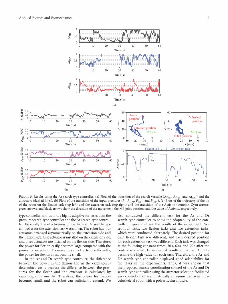
In Figure 5, Activity increased after 10 s and reached aconstant value of 0.91 at 17 s. The flexion task was close tobeing accomplished, but compared with the pressuresearch-type controller, the accomplishment ratio was 5%lower and the control time for accomplishment of the taskwas 13 s longer. Therefore, the control was not as good as thatof the pressure search-type controller. In the extension task,Activity did not attain a high value. Therefore, the extensiontask was not accomplished. As a result, the controller did notwork well for the extension task. To efficiently accomplishthe task, it was necessary that the differences between thepressures for the extensor and the flexors be easily calculated
by the controller because the differences can decrease powerwhich prevents accomplishment of tasks and can make thetip position of the robot move quickly to the desired position,but this controller cannot calculate the differences betweenthe pressures as well as the pressure search-type controller.This controller searches for three Ar values independently.Therefore, each Ar takes on a different value, and the pres-sure for the flexor does not decrease satisfactorily. Thus, thepower for flexion does not decrease sufficiently, and theextension task is not accomplished.
In Figure 6, Activity increased greatly and became con-stant at 0.95 for the flexion task. On the extension task, Activity increased gradually right after the change of the task andbecame constant at 0.97. Therefore, the flexion task and theextension task were accomplished. The Ar and Dr search-
0 10 20 30 40 50 60Time (s)
xe
0 10 20 30 40 50 60Time (s)
xM
Pf
0 10 20 30 40 50 600
0.51
00.5
1
00.5
1
00.5
1
Time (s)
xPI
Pf
0 10 20 30 40 50 60Time (s)
xD
IPf
(a)
Time (s)
Time (s)
Time (s)
Time (s)
0 10 20 30 40 50 600
0.10.2
Pe (
MPa
)P
MPf
(MPa
)P
PIPf
(MPa
)P
DIP
f (M
Pa)
0 10 20 30 40 50 600
0.10.2
0 10 20 30 40 50 600
0.10.2
0 10 20 30 40 50 600
0.10.2
(b)
0 10 20 30 40 50 600
0.5
1
Time (s)
Act
ivity
↑ 0.96
← 0.85Flexion task Extension task
−30 −20 −10 0 100
20
40
60
x (mm)
y (m
m)
y (m
m)↓
←↑
Desired position
→Initial position
↓
MP joint
−30 −20 −10 0 100
20
40
60
→Desiredposition ←
Activity = 0.85
↓
MP joint
x (mm)
(c)
Figure 4: Results using the pressure search-type controller. (a) Plots of the transition of the search variables (xe, xMPf , xPIPf , and xDIPf ) and theattractors (dashed lines). (b) Plots of the transition of the input pressures (Pe, PMPf , PPIPf , and PDIPf ). (c) Plots of the trajectory of the tip of therobot for the flexion task (top-left) and the extension task (top-right) and the transition of the Activity (bottom). Cyan arrows, green arrows,and black arrows show the direction of the movement, the MP joint position, and the value of Activity, respectively.
6 Applied Bionics and Biomechanics
type controller is, thus, more highly adaptive for tasks than thepressure search-type controller and theAr search-type control-ler. Especially, the effectiveness of the Ar and Dr search-typecontroller for the extension task was shown. The robot has fouractuators arranged asymmetrically on the extension side andthe flexion side. One actuator is installed on the extension side,and three actuators are installed on the flexion side. Therefore,the power for flexion easily becomes large compared with thepower for extension. To make this robot extend sufficiently,the power for flexion must become small.
In the Ar and Dr search-type controller, the differencebetween the power in the flexion and in the extension isdetermined easily because the difference between the pres-sures for the flexor and the extensor is calculated bysearching only one Ar. Therefore, the power for flexionbecomes small, and the robot can sufficiently extend. We
also conducted the different task for the Ar and Drsearch-type controller to show the adaptability of the con-troller. Figure 7 shows the results of the experiment. Weset four tasks, two flexion tasks and two extension tasks,which were conducted alternately. The desired position foreach flexion task was different, and each desired positionfor each extension task was different. Each task was changedat the following constant times: 30 s, 60 s, and 90 s after thecontrol is started. Experimental results show that Activitybecame the high value for each task. Therefore, the Ar andDr search-type controller displayed good adaptability forthe tasks in the experiments. Thus, it was shown thatthe proposed muscle coordination control of the Ar and Drsearch-type controller using the attractor selection facilitatedeasy control of an asymmetrically antagonistic-driven mus-culoskeletal robot with a polyarticular muscle.
0 10 20 30 40 50 600
0.5
1
0
0.5
1
0
0.5
1
Time (s)
Ar M
P0 10 20 30 40 50 60
Time (s)
Ar P
IP
0 10 20 30 40 50 60Time (s)
Ar D
IP
(a)
0 10 20 30 40 50 60Time (s)
0 10 20 30 40 50 60Time (s)
0 10 20 30 40 50 60Time (s)
0 10 20 30 40 50 60Time (s)
00.10.2
Pe (M
Pa)
PM
Pf (M
Pa)
PPI
Pf (M
Pa)
PD
IPf (M
Pa)
00.10.2
00.10.2
00.10.2
(b)
Time (s)0 10 20 30 40 50 60
0
0.5
1
Act
ivity
↑ 0.91
Flexion task Extension task
−30 −20 −10 0 100
20
40
60
x (mm)
y (m
m)
−30 −20 −10 0 100
20
40
60
x (mm)
y (m
m)↓←
↓↑
←Desired position
→ Initial position
↓
MP joint
↑Desired position
↑Initial position ↓
MP joint
(c)
Figure 5: Results using the Ar search-type controller. (a) Plots of the transition of the search variable (ArMP, ArPIP, and ArDIP) and theattractors (dashed lines). (b) Plots of the transition of the input pressures (Pe, PMPf , PPIPf , and PDIPf ). (c) Plots of the trajectory of the tipof the robot on the flexion task (top-left) and the extension task (top-right) and the transition of the Activity (bottom). Cyan arrows,green arrows, and black arrows show the direction of the movement, the MP joint position, and the value of Activity, respectively.
7Applied Bionics and Biomechanics

5. Conclusions
This work demonstrated a muscle coordination control of anasymmetrically antagonistic-driven musculoskeletal robotusing attractor selection which is a biologically inspiredsearch method.
First, muscle coordination control models of the musculo-skeletal robot were built using virtual antagonistic musclestructures with a virtually symmetric arrangement of muscles,and the calculation methods of the input pressure for PAMs ofthe musculoskeletal robot with and without muscle coordina-tion were shown. Next, the attractor selection was applied toboth the muscle coordination control model and to anothercontrol model without the muscle coordination to comparethe control performance. Finally, position control experiments
were conducted, the effectiveness of the proposed muscle coor-dination control applied to the attractor selection was demon-strated, and it was also shown to be faster and more robust toaccomplish the task by generating control commands virtuallyassuming a symmetrical and simpler metastructure rather thanproviding a control command according to the actual complex(asymmetric) antagonistic muscle structure.
Based on the virtual antagonistic muscle structure pro-posed in this research, we may be able to build a musculo-skeletal robot that achieves a more complicated task fasterby devising how to give noise [25] and adaptively updatingthe attractor structure [21]. In future work, the muscle coor-dination control method, using the attractor selection, will beapplied to the multifingered robot hand formed by increasingthe number of musculoskeletal robots (i.e., robot fingers).
0 10 20 30 40 50 600
0.5
1
0
0.5
1
0
0.5
1
Time (s)
Ar
0 10 20 30 40 50 60Time (s)
Dr M
P
0 10 20 30 40 50 60Time (s)
Dr P
IP
(a)
0 10 20 30 40 50 60Time (s)
0 10 20 30 40 50 60Time (s)
0 10 20 30 40 50 60Time (s)
0 10 20 30 40 50 60Time (s)
00.10.2
Pe (M
Pa)
PM
Pf (M
Pa)
PPI
Pf (M
Pa)
PDI
Pf (M
Pa)
00.10.2
00.10.2
00.10.2
(b)
0 10 20 30 40 50 600
0.5
1
Time (s)
Act
ivity
↑0.95
↑0.97
Flexion task Extension task
−30 −20 −10 0 100
20
40
60
x (mm)−30 −20 −10 0 10
x (mm)
y (m
m) ↓←
← Desired position
→Initialposition
↓MP joint
0
20
40
60
y (m
m) ←
Desiredposition
↓
Initialposition
↓MP joint
↑→
(c)
Figure 6: Results using the Ar and Dr search-type controller. (a) Plots of the transition of the search variable (Ar, DrMPf , and DrPIPf ) and theattractors (dashed lines). (b) Plots of the transition of the input pressures (Pe, PMPf , PPIPf , and PDIPf ). (c) Plots of the trajectory of the tip of therobot on the flexion task (top-left) and the extension task (top-right) and the transition of the Activity (bottom). Cyan arrows, green arrows,and black arrows show the direction of the movement, the MP joint position, and the value of Activity, respectively.
8 Applied Bionics and Biomechanics

Furthermore, the effectiveness of the control method will beinvestigated for asymmetrically antagonistic-driven muscu-loskeletal robots, which have entirely different arrangementsof muscles compared with our musculoskeletal robot.
The muscle coordination control method using attractorselection can be applied not only to musculoskeletal robotsbut also to human hands. Therefore, the control method willbe applied to rehabilitation using functional electrical stimu-lations (FESs) [26, 27] as a novel approach to controllinghuman hands.
Data Availability
The raw data for Figures 4–7 are available from the corre-sponding author upon request.
Conflicts of Interest
The authors declare that there is no conflict of interestregarding the publication of this paper.
Acknowledgments
This work was supported by JSPS KAKENHI Grant nos.JP23560524, JP26420196, and JP17K06259.
References
[1] I. Mizuuchi, T. Yoshikai, Y. Sodeyama et al., “Development ofmusculoskeletal humanoid Kotaro,” in Proceedings 2006 IEEE
0 20 40 60 80 100 1200
0.5
1
0
0.5
1
0
0.5
1
Time (s)
Ar
0 20 40 60 80 100 120Time (s)
Dr M
P
0 20 40 60 80 100 120Time (s)
Dr P
IP
(a)
0 20 40 60 80 100 120Time (s)
0 20 40 60 80 100 120Time (s)
0 20 40 60 80 100 120Time (s)
0 20 40 60 80 100 120Time (s)
00.10.2
Pe (M
Pa)
PM
Pf (M
Pa)
PPI
Pf (M
Pa)
PD
IPf (M
Pa)
00.10.2
00.10.2
00.10.2
(b)
0 20 40 60 80 100 1200
0.5
1
Time (s)
Act
ivity
→ 0.91→ 0.93→ 0.97→ 0.93
Flexion task Extension task Flexion task Extension task
−20 0 200
20
40
60
x (mm)
y (m
m)
−20 0 200
20
40
60
x (mm)y
(mm
)−20 0 20
0
20
40
60
x (mm)
y (m
m)
−20 0 200
20
40
60
x (mm)
y (m
m)↓
↑ ←↓
↑
(c)
Figure 7: Results using the Ar and Dr search-type controller at four desired positions. (a) Plots of the transition of the search variable(Ar, DrMPf , and DrPIPf ). (b) Plots of the transition of the input pressures (Pe, PMPf , PPIPf , and PDIPf ). In (c), the top images plot the trajectoryof the tip of the robot: the first flexion task, the first extension task, the second flexion task, and the second extension task from the left image,whereas the bottom image plots the transition of the Activity. Cyan arrows and black arrows show the direction of the movement and thevalue of Activity, respectively.
9Applied Bionics and Biomechanics

International Conference on Robotics and Automation, 2006.ICRA 2006, pp. 82–87, Orlando, FL, USA, May 2006.
[2] H. G. Marques, M. Jantsch, S. Wittmeier et al., “ECCE1: thefirst of a series of anthropomimetic musculoskeletal uppertorsos,” in 2010 10th IEEE-RAS International Conference onHumanoid Robots, vol. 6-8, pp. 391–396, Nashville, TN,USA, December 2010.
[3] N. C. Park and H. S. Yang, “Control of a flexible manipulatorwith artificial muscle-type pneumatic actuators, using μ-syn-thesis,” Journal of Vibration and Control, vol. 4, no. 4,pp. 481–502, 1998.
[4] T. V. Minh, B. Kamers, T. Tjahjowidodo, H. Ramon, andH. Van Brussel, “Modeling torque-angle hysteresis in a pneu-matic muscle manipulator,” in 2010 IEEE/ASME InternationalConference on Advanced Intelligent Mechatronics, pp. 1122–1127, Montreal, ON, Canada, July 2010.
[5] T. D. C. Th;anh and K. K. Ahn, “Nonlinear PID control toimprove the control performance of 2 axes pneumatic artificialmuscle manipulator using neural network,” Mechatronics,vol. 16, no. 9, pp. 577–587, 2005.
[6] B. Verrelst, R. V. Ham, B. Vanderborght, F. Daerden,D. Lefeber, and J. Vermeulen, “The pneumatic biped “Lucy”actuated with pleated pneumatic artificial muscles,” Autono-mous Robots, vol. 18, no. 2, pp. 201–213, 2005.
[7] A. Rezoug, S. Boudoua, and F. Hamerlain, “Fuzzy logic controlfor manipulator robot actuated by pneumatic artificial mus-cles,” Journal of Electrical Systems, vol. 1, pp. 1–6, 2009.
[8] K. K. Ahn and H. T. C. Nguyen, “Intelligent switching controlof a pneumatic muscle robot arm using learning vector quan-tization neural network,” Mechatronics, vol. 17, no. 4-5,pp. 255–262, 2007.
[9] Y. Honda, F. Miyazaki, and A. Nishikawa, “Control of pneu-matic five-fingered robot hand using antagonistic muscle ratioand antagonistic muscle activity,” in 2010 3rd IEEE RAS &EMBS International Conference on Biomedical Robotics andBiomechatronics, pp. 337–342, Tokyo, Japan, September 2010.
[10] Y. Honda, F. Miyazaki, and A. Nishikawa, “Angle control ofpneumatically-driven musculoskeletal model using antagonis-tic muscle ratio and antagonistic muscle activity,” in 2010 IEEEInternational Conference on Robotics and Biomimetics,pp. 1722–1727, Tianjin, China, December 2010.
[11] T. Yanagida, M. Ueda, T. Murata, S. Esaki, and Y. Ishii, “Brow-nian motion, fluctuation and life,” Biosystems, vol. 88, no. 3,pp. 228–242, 2007.
[12] A. Kashiwagi, I. Urabe, K. Kaneko, and T. Yomo, “Adaptiveresponse of a gene network to environmental changes byfitness-induced attractor selection,” PLoS One, vol. 1, no. 1,article e49, 2006.
[13] D. Tian, J. Zhou, Z. Sheng, Y. Wang, and J. Ma, “From cellularattractor selection to adaptive signal control for traffic net-works,” Scientific Reports, vol. 6, no. 1, article 23048, 2016.
[14] G. Motoyoshi, K. Leibnitz, andM. Murata, “Proposal and eval-uation of a future mobile network management mechanismwith attractor selection,” EURASIP Journal on Wireless Com-munications and Networking, vol. 2012, no. 1, 2012.
[15] D. Tian, J. Zhou, H. Qi et al., “A bio-inspired QoS-orientedhandover model in heterogeneous wireless networks,” Journalof AppliedMathematics, vol. 2014, Article ID 920123, 13 pages,2014.
[16] T. Chikaraishi, T. Minato, and H. Ishiguro, “Development ofan android system integrated with sensor networks,” Journal
of Information Processing Society of Japan, vol. 49, no. 12,pp. 3821–3834, 2008.
[17] S. G. Nurzaman, Y. Matsumoto, Y. Nakamura, S. Koizumi, andH. Ishiguro, “Attractor selection based biologically inspirednavigation system,” in In Proceedings of the 39nd ISR(Interna-tional Symposium on Robotics), pp. 837–842, Seoul, Korea,October 2008.
[18] S. G. Nurzaman, X. Yu, Y. Kim, and F. Iida, “Guided self-organization in a dynamic embodied system based on attractorselection mechanism,” Entropy, vol. 16, no. 5, pp. 2592–2610,2014.
[19] Y. Kim, S. G. Nurzaman, F. Iida, and E. F. Fukushima, “A selforganization approach to goal-directed multimodal locomo-tion based on attractor selection mechanism,” in 2015 IEEEInternational Conference on Robotics and Automation (ICRA),pp. 5061–5066, Seattle, WA, USA, May 2015.
[20] I. Fukuyori, Y. Nakamura, Y. Matsumoto, and H. Ishiguro,“Flexible control mechanism for multi-DOF robotic arm basedon biological fluctuation,” in SAB '08 Proceedings of the 10thinternational conference on Simulation of Adaptive Behavior:From Animals to Animats, pp. 22–31, Osaka, Japan, July 2008.
[21] A. Sugahara, Y. Nakamura, I. Fukuyori, Y. Matsumoto, andH. Ishiguro, “Generating circular motion of a human-likerobotic arm using attractor selection model,” Journal of Robot-ics and Mechatronics, vol. 22, no. 3, pp. 315–321, 2010.
[22] A. De Rengerve, S. Boucenna, P. Andry, and P. Gaussier,“Emergent imitative behavior on a robotic arm based onvisuo-motor associative memories,” in 2010 IEEE/RSJ Interna-tional Conference on Intelligent Robots and Systems, pp. 1754–1759, Taipei, Taiwan, October 2010.
[23] A. Nishikawa, K. Taniguchi, M. Sekimoto et al., “Design andcontrol of a compact laparoscope manipulator: a biologicallyinspired approach,” in Advanced Strategies for Robot Manipu-lators, S. Ehsan Shafiei, Ed., pp. 365–380, Intech Open, 2010.
[24] S. Ide and A. Nishikawa, “Bio-inspired control of a multi-fingered robot hand with musculoskeletal system,” in SmartTextiles and Their Applications, V. Koncar, Ed., pp. 185–195,Elsevier, 2016.
[25] S. G. Nurzaman, Y. Matsumoto, Y. Nakamura, K. Shirai,S. Koizumi, and H. Ishiguro, “From Lévy to Brownian: a com-putational model based on biological fluctuation,” PLoS One,vol. 6, no. 2, article e16168, 2011.
[26] K. Matsui, Y. Hishii, K. Maegaki et al., “Equilibrium-pointcontrol of human elbow-joint movement under isometricenvironment by using multichannel functional electrical stim-ulation,” Frontiers in Neuroscience, vol. 8, p. 164, 2014.
[27] K. Takemura, M. Kurosawa, K. Atsuumi, K. Matsui,F. Miyazaki, and A. Nishikawa, “Frequency domain systemidentification of human finger dynamics using functionalelectrical stimulation based on an agonist-antagonist con-cept,” in Proceedings of the 2017 Annual Conference of theInternational Functional Electrical Stimulation Society,p. 114, London, UK, July 2017.
10 Applied Bionics and Biomechanics

International Journal of
AerospaceEngineeringHindawiwww.hindawi.com Volume 2018
RoboticsJournal of
Hindawiwww.hindawi.com Volume 2018
Hindawiwww.hindawi.com Volume 2018
Active and Passive Electronic Components
VLSI Design
Hindawiwww.hindawi.com Volume 2018
Hindawiwww.hindawi.com Volume 2018
Shock and Vibration
Hindawiwww.hindawi.com Volume 2018
Civil EngineeringAdvances in
Acoustics and VibrationAdvances in
Hindawiwww.hindawi.com Volume 2018
Hindawiwww.hindawi.com Volume 2018
Electrical and Computer Engineering
Journal of
Advances inOptoElectronics
Hindawiwww.hindawi.com
Volume 2018
Hindawi Publishing Corporation http://www.hindawi.com Volume 2013Hindawiwww.hindawi.com
The Scientific World Journal
Volume 2018
Control Scienceand Engineering
Journal of
Hindawiwww.hindawi.com Volume 2018
Hindawiwww.hindawi.com
Journal ofEngineeringVolume 2018
SensorsJournal of
Hindawiwww.hindawi.com Volume 2018
International Journal of
RotatingMachinery
Hindawiwww.hindawi.com Volume 2018
Modelling &Simulationin EngineeringHindawiwww.hindawi.com Volume 2018
Hindawiwww.hindawi.com Volume 2018
Chemical EngineeringInternational Journal of Antennas and
Propagation
International Journal of
Hindawiwww.hindawi.com Volume 2018
Hindawiwww.hindawi.com Volume 2018
Navigation and Observation
International Journal of
Hindawi
www.hindawi.com Volume 2018
Advances in
Multimedia
Submit your manuscripts atwww.hindawi.com