Embed Size (px)
Citation preview
PHYSICAL REVIEW SPECIAL TOPICS - ACCELERATORS AND BEAMS 8, 034202 (2005)
Multivariate optimization of a high brightness dc gun photoinjector
Ivan V. Bazarov* and Charles K. Sinclair†
Laboratory for Elementary Particle Physics, Cornell University, Ithaca, New York 14853, USA(Received 1 February 2005; published 24 March 2005)
*Electronic†Electronic
1098-4402=
We have conducted a multiobjective computational optimization of a high brightness, high averagecurrent photoinjector under development at Cornell University. This injector employs a dc photoemissionelectron gun. Using evolutionary algorithms combined with parallel computing resources, the multivariateparameter space of the photoinjector was explored for optimal values. This powerful computational toolallows an extensive study of complex and nonlinear systems such as the space-charge dominated regionsof an accelerator, and has broad areas of potential application to accelerator physics and engineeringproblems. In the present case, the optimized injector is simulated to deliver beam of very high quality(e.g., a rms normalized emittance of 0.1 mm mrad for 0.1 nC, and 0.7 mm mrad for 1 nC bunches). Thefield strengths of the active elements of the injector are moderate and technically practical. The relevanceof these results to various novel linac-based accelerator proposals is pointed out.
DOI: 10.1103/PhysRevSTAB.8.034202 PACS numbers: 29.25.Bx
I. INTRODUCTION
The successful operation of a cw energy recovery linac(ERL) with moderate beam current for the JeffersonLaboratory free electron laser [1], combined with thedemonstration of reliable high gradient operation of cwsuperconducting accelerator cavities at several laboratories[2,3], has led to great current interest in developing ERLsfor a number of applications. These applications includeelectron cooling [4], very high power free electron lasers,linac-ring versions of an electron-ion collider [5], and theproduction of high brightness, short pulse synchrotronradiation x-ray beams [6]. All of these applications re-quire the development of high average current, high bright-ness electron injectors. Average currents approachingan Ampere, with transverse and longitudinal emittanceslower than the present state-of-the-art, are currently beingdiscussed.
Prior to the development of ERLs, the need for highaverage current electron injectors was limited by the prac-tical problems in accelerating such currents to even mod-erate beam energies. To date, most high average currentelectron injectors have employed dc electron guns deliver-ing cw or long pulse beams from gridded thermionicemission cathodes. The beam from these guns is driftbunched, sometimes following rf chopping, subharmonicbunching, or prebunching systems, to produce a bunchedbeam for subsequent acceleration. In such injectors, theemittance is limited by the relatively high thermal emit-tance of the cathode, effects due to the grid, and emittancegrowth during the bunching process.
More recently, photoemission cathodes have been uti-lized for high brightness electron injectors. In conjunctionwith suitable short pulse lasers, photoemission cathodescan deliver a bunched beam directly from the electron gun.
address: [email protected]: [email protected]
05=8(3)=034202(14) 03420
The cathode current density can be significantly higherthan that from a thermionic cathode, leading to the possi-bility of high beam brightness. The absence of a grid, andexcellent cathode smoothness, eliminate these emittancedegrading effects. Negative electron affinity photocathodesoffer the possibility of a very small thermal emittance.Electron injectors employing photoemission cathodeshave delivered average currents of 9.1 mA in a train of0.122 nC bunches from a dc gun [7], and 32 mA in a trainof 4.74 nC bunches from a 433 MHz rf gun [8].
Photoemission electron guns are operated very differ-ently from thermionic guns. The photocathode is generallyneither fully nor uniformly illuminated, in contrast to athermionic gun, where the full cathode area delivers arelatively uniform current density in space-charge limitedflow. Short duration pulses leaving a photocathode fill onlya small fraction of the cathode-anode gap, and space-charge forces lengthen the bunch and degrade the emit-tance from the photocathode onward. Delivering evenmoderate bunch charges in a very short duration pulsefrom a small cathode area requires a substantial electricfield at the photocathode at the time of photoemission. Thisreality has led to the development of rf photoinjectors, inwhich a photoemission cathode is mounted in the end wallof a rf accelerating structure, allowing a very high electricfield to be applied to the photocathode at the time ofphotoemission. The discovery that certain focusing con-ditions following a photoemission electron gun could re-cover much of the space-charge induced emittance growthhas led to the development of a number of electron injec-tors providing high peak brightness beams [9].
For true cw applications, room temperature rf guns havelimited utility, since the cavity field strength is limited bypower dissipation in the cavity walls. Superconducting rf(SRF) guns offer an obvious solution to this problem, andhave been demonstrated [10–12], but their practical im-plementation to deliver high average current and high
2-1 2005 The American Physical Society
BAZAROV AND SINCLAIR Phys. Rev. ST Accel. Beams 8, 034202 (2005)
brightness beams presents a number of technical chal-lenges. An alternative for cw applications is a dc electrongun, in which field emission from the cathode electrodestructure is the principal phenomenon limiting the cathodefield strength. The required cathode field strength may beminimized by delivering a relatively long duration bunchfrom the photocathode, and using conventional driftbunching. By using a low thermal emittance photocathode,the transverse size of the illuminated spot at the cathodecan be increased while meeting the total emittance goal. Alonger bunch and a larger spot size both reduce the detri-mental space-charge effects.
Determining the optimal parameter set for a high aver-age current dc photoemission electron source with driftbunching is not a simple task. In general, one expects theoptimal solution to be dependent on the bunch charge, thecathode field strength and gun voltage, the transverse andlongitudinal profiles of the laser illumination at the photo-cathode, and the locations and field strengths of the focus-ing, bunching, and accelerating elements following theelectron gun. There are many practical constraints involv-ing the physical size of the elements, practical fieldstrengths, and the realities of the vacuum system. Thenonlinear nature of the space-charge force precludes ob-taining meaningful analytic estimates. Present day codesallow good quality results to be obtained in tracking abunch through a complete injector, but the large numberof parameters and constraints involved makes a completeinjector optimization formidable.
At Cornell University, we are planning the constructionof an ERL-based synchrotron radiation x-ray source. Thegoals of this project are to produce x-ray beams offeringexceptionally high brightness, high coherence, and veryshort duration x-ray pulses to allow pump-probe experi-ments. Ultimately, we would like to deliver diffractionlimited x-ray beams at 1 �A wavelength, requiring a geo-metric emittance of 8 pm rad at 5 GeV beam energy. Thequality of the beam delivered from the electron injector is acrucial aspect of this project. Our assessment of currenttechnology led us to design an injector based on a very highvoltage dc photoemission electron gun, illuminated withmoderate duration optical pulses from a cw laser, andfollowed by conventional drift bunching and an SRF ac-celerator. We developed a design for such an injector thatmet our baseline goals of 77 pC per bunch at a bunchrepetition rate of 1300 MHz (corresponding to 100 mAaverage current), with a normalized emittance below 2 mmmrad at 5 GeV, and a bunch length of 0.7 mm rms [13].
With a baseline injector design in hand, it is natural toinvestigate the extent to which the design might be im-proved. In this paper, we report the results of an extensivecomputational optimization of our original injector design.This optimization was conducted using large scale parallelprocessing, originally with a dedicated cluster computerhaving 128 2 GHz processors, and ultimately using the
03420
available computational power on the many desktop com-puters on the laboratory network.
This paper is organized in the following fashion: inSec. II we describe the development of evolutionary algo-rithms and their implementation in a parallel computingenvironment. Then we summarize the parameters used inour optimization problem. In Sec. III we present the im-provements obtained in the simulated electron beam prop-erties. In particular, we show how the use of multiobjectiveevolutionary algorithms helped us address the followingquestions: What is the optimal transverse and longitudinalshape of the laser pulse? How high should the gun voltagebe for good injector performance? How does the thermalemittance of the photocathode affect the final emittance?What are the trade-offs between bunch length, emittance,and bunch charge? We conclude with a brief discussion ofour results, and the prospects for future developmentsusing this powerful computational technique.
II. ALGORITHMS
The large number of variables and constraints in theproblem under consideration (the field strengths of variouselements in the injector, their physical size and positionalong the beam line, the phases of time dependent fields,and initial beam distributions at the photocathode) and thefact that each simulation through the injector is time con-suming poses a challenge for performing any meaningfuloptimization in a reasonable amount of time. As it ispointed out in [14], there are three ways of doing a jobfaster, namely, (1) work harder, (2) work smarter, and(3) get help. In the world of computers these translateinto (1) higher processor speed, (2) better algorithms, and(3) parallel processing. The fact that the injector optimi-zation involves conflicting objectives (e.g., minimize emit-tance, maximize bunch charge, minimize bunch length,etc.), and the need for parallelization to increase thethroughput make multiobjective evolutionary algorithmsa suitable choice for the task. The primary algorithm usedto obtain the results presented in this paper is a modifiedversion of SPEA2 (strength Pareto evolutionary algorithm 2)[15]. NSGA-II (nondominated sorting genetic algorithm II)[16] was also used in these optimizations and demonstratedsimilar performance to SPEA2 when specifying two objec-tive functions. However, it did not give as good a spread ofsolutions in higher dimensions of objective space.
For the convenience of readers not familiar with evolu-tionary algorithms, we provide a brief overview of theirmost salient features and then describe our particular im-plementation. A vast literature on multiobjective evolu-tionary algorithms is available. The interested reader isreferred to [17,18] for more details on the subject.
A. Multiobjective evolutionary algorithms
We begin by providing several definitions important fordescribing the way an evolutionary algorithm performs,
2-2

MULTIVARIATE OPTIMIZATION OF A HIGH . . . Phys. Rev. ST Accel. Beams 8, 034202 (2005)
and for visualization of optimization results. A multiob-jective optimization problem can be formulated as follows:
maximize fm�x1; x2; . . . ; xn�; m � 1; 2; . . . ;M;subject to gj�x1; x2; . . . ; xn� � 0; j � 1; 2; . . . ; J;
x�L�i � xi � x�U�i ; i � 1; 2; . . . ; n:
9>=>;
Objective functions f�x� � �f1�x�; f2�x�; . . . ; fM�x��map n-dimensional decision variable space D of vectorx � �x1; x2; . . . ; xn�, bounded with lower and upper limitsx�L� and x�U�, respectively, into M-dimensional objectivespace Z. The goal is to find all (or as many as possible)solutions x that maximize each objective function fm�x�subject to J inequality constraints gj�x� � 0. Here we donot consider equality constraints, which are more difficultto deal with in practice. A solution x that satisfies allconstraints and variable bounds is called feasible (as op-posed to infeasible) and the set of all feasible solutionsrepresents the feasible region S in the decision variablespace D.
An important concept that allows one to compare fea-sible solutions with multiple objectives is that of domina-tion, which is defined as follows:Definition 1. A feasible solution xa is said to dominateanother feasible solution xb, or xa � xb, if the solution xais not worse than xb in all objectives and xa is strictlybetter than xb in at least one objective. In otherwords, 8 m 2 1; 2; . . . ;M : fm�xa� � fm�xb� and 9 m0 21; 2; . . . ;M : fm0 �xa�> fm0 �xb�.
The dominance relation is transitive (i.e. xa � xc if xa �xb and xb � xc) and this property allows a binary relationas an ordering operator (since the dominance relation is notreflexive, i.e., no solution dominates itself, a set that isordered in this fashion represents an instance of what isknown in mathematical literature as quasiorder). Thus, theconcept of dominance allows sorting of trial solutionsduring multiobjective optimization. In particular, one isinterested in finding a nondominated set:Definition 2. Among a set of solutions P , the nondomi-nated subset of solutions P 0 are those that are not domi-nated by any member of the set P .
The better solutions will comprise the nondominated set,and provide direction for the optimization search. Whenthe set P is the entire search space, the resulting non-dominated set is called the Pareto-optimal set. Clearly, ifone is able to find the Pareto-optimal set of solutions, themultiobjective optimization problem is solved.
In Definition 1 the two solutions xa and xb alreadybelong to the feasible region S. In general, however, find-ing the region of feasible solutions can be a challenge initself. Using the definition of constrain-domination allowsclassification of trial solutions independent of whether thesolutions are feasible or infeasible.Definition 3. A solution xa is said to constrain-dominate asolution xb, or xa �c xb, if any of the following conditionsare true:
03420
1. Solution xa is feasible and solution xb is infeasible.2. Solutions xa and xb are both infeasible, but solution
xa has smaller constraint violation, i.e., dominates xbwith respect to constraint functions for 8 j0 21; 2; . . . ; J : gj0 �xa�< 0 or gj0 �xb�< 0.
3. Solutions xa and xb are both feasible and xa domi-nates xb according to Definition 1.
In the early stages of optimization, the constrain-dominance relation tends to emphasize feasible solutionsover infeasible solutions, while at a later stage, when mosttrial solutions are found in the feasible region S, thedominance relation becomes more prominent, favoringsolutions with better objective functions.
Evolutionary (or genetic) algorithms vary widely in theirparticulars, but they share several common properties.These include working with a population of solutionsrather than a single solution, and using stochastic operatorsto both emphasize better solutions and to create new trialsolutions. The former makes these methods well-suited foroptimizations with more than one objective, i.e., a multi-objective optimization problem, while the latter makesthem generally applicable to solving a broad range ofproblems, since no particular structure of the problem isassumed in the algorithms. Furthermore, these methods donot use any gradient information, avoiding the potentiallynoisy calculation of derivatives, and allowing their use incases where gradient information is not readily available.Finally, because these algorithms work with a popula-tion of solutions, they can be easily adapted for parallelprocessing.
A typical evolutionary algorithm works as follows. Alarge number (e.g., a few hundred) of initial trial solutionsis generated by randomly assigning vectors x in space D.Objective functions f�x� and constraints g�x� are evaluatedfor this population. A fitness value is assigned to eachmember of the population based on a comparison relationsuch as constrain-domination. A selection operator is thenapplied to create a mating pool of some fixed size with apreference for solutions with better fitness. Thus, betterfitness solutions tend to have more copies in the matingpool than less desirable solutions. A crossing operator thengenerates new offspring solutions from parent solutions inthe mating pool. An optional mutation operator may beused to diversify the offspring by perturbing the new off-spring solutions in some fashion. The offspring solutionsgenerated by these selection, crossing, and mutation op-erations are carried over to the next generation and theprocess is repeated. The ideas underlying these operationsare that solutions from the full decision space will beadequately sampled, and that better fitness solutions willbe selected, tending to produce more successful offspringand moving the solutions toward the true Pareto-optimalfront.
In elitist evolutionary algorithms, such as NSGA-II andSPEA2, the selection operator is elite-preserving, i.e., the
2-3

BAZAROV AND SINCLAIR Phys. Rev. ST Accel. Beams 8, 034202 (2005)
best solutions (e.g., the current nondominated set) fromamong both parents or some externally maintained archive,and the offspring are carried over to the subsequent gen-erations. Elitism ensures that good solutions found previ-ously do not get lost in later generations and always get achance for representation in the mating pool, improving theoverall performance of the evolutionary algorithm.Furthermore, to ensure that the final nondominated setcontains solutions that are well distributed in objective Zor solution D spaces, the selection operator is chosen sothat solutions from less crowded regions, which are other-wise equivalent with respect to the dominance relation, areemphasized over ones from more crowded regions.
B. Implementation
The computational bottleneck in injector optimization isthe calculation of objective and constraint functions, as thisstep requires particle tracking through the injector withspace charge included. To reduce the wall-clock time forthese calculations to a reasonable value, parallel processingis used.
Evaluation of objectives and constraints of a populationof solutions from a single generation is ideal for parallelprocessing. Computation of the objective and constraintfunctions of a particular trial solution is done on a singleprocessor. The message passing between various processesoccurs only at the end of each generation, when selectionand crossing of the individuals in the whole populationtakes place. Thus, parallelization of evolutionary algo-rithms does not require high-bandwidth low-latency inter-connections of the various nodes in a cluster, and evencomputers that are part of a usual network form an effec-tive parallel environment for doing optimizations.
A single evaluation of a new trial solution requires avariable length of time, due, for example, to the varyingcomplexity of its data set, or to the processor speed ordifferent work loads on individual computers. It is thusinevitable that near the end of the computations for eachgeneration, a considerable fraction of the computing nodeswould be waiting for the last exchange of information,from those few evaluations taking the longest time, withthe main processor responsible for performing the evolu-tionary algorithm operations. To circumvent this undesir-able situation, the algorithm begins running a newgeneration by applying a premature selection from a subsetof the evaluated fraction of the population, sending the newoffspring trial solutions to inactive nodes for evaluationuntil no idle node remains. This way, more trial solutionsthan the number of available nodes are generated in thebeginning, and the solutions which have not been evaluatedare kept in a waiting queue. As soon as a node finishes itsprevious job and becomes available, a trial solution fromthis queue is sent to it for evaluation. When the waitingqueue becomes empty, the algorithm performs evolution-ary operations (selection, crossing, mutation, etc.) on the
03420
population that now includes the newly evaluated solu-tions. This completes the cycle and a new generation isstarted. This way the idle time in the system is dramaticallyreduced, and the longer time required for the evaluationof some trial solutions does not retard the overallperformance.
Parallel implementation of the evolutionary algorithmswas realized on two 64 and 32 dual-processor clustercomputers, as well as nearly 100 desktop computers withinthe laboratory’s network. The latter were utilized as a latentcomputational resource, performing trial solution evalu-ations in the background when their normal work loadwas minimal. A ‘‘master-slave’’ model for algorithm exe-cution was used: the master processor performs all theevolutionary operations on the ordered population of eval-uated trial solutions, and sends the trial solutions to theslaves for evaluation.
It should be noted that in doing this parallelization, theassociation of a particular solution with a particular gen-eration is lost, though this is without consequence to thefinal optimization.
A Platform and Programming Language IndependentInterface for Search Algorithms (PISA) library [19] pro-vided the framework for using existing evolutionary algo-rithms as well as for developing new ones. The algorithmsof the library were modified to include constraint handlingthrough the constrain-domination relation. The underlyingfeature of PISA is to separate algorithms into two looselycoupled parts: variator and selector. The selector containsalgorithm specific operations, such as assigning fitness toan entire population and creating a new mating pool withbetter solutions from this population based on a specificalgorithm. The variator, on the other hand, contains prob-lem specific implementation (e.g., provides objectives andconstraints for new decision variables) as well as crossingand mutation operators acting on the individuals chosen bythe selector and passed to the variator. Parallelization in-volves modifying the variator only, which can then becombined with any particular version of the selector toform a working optimization algorithm. This way one isable to apply various evolutionary algorithms to the prob-lem without the need to reprogram.
We used the program ASTRA [20] as the space-chargecode to evaluate the objective and constraint functions.This choice was motivated by the good trade-off betweenspeed and performance available in ASTRA, as well as the‘‘low-maintenance’’ nature of the code (e.g., automaticmesh calculation).
C. Problem setup
The injector system under study is described in [13]. Aschematic layout of the various beam line elements isshown in Fig. 1. The high-voltage dc gun is followed bytwo focusing solenoids, one before and one after a single-
2-4

FIG. 1. (Color) Schematic of the dc gun injector layout.
MULTIVARIATE OPTIMIZATION OF A HIGH . . . Phys. Rev. ST Accel. Beams 8, 034202 (2005)
cell, normal conducting buncher cavity. A cryomodulecontaining five 2-cell superconducting cavities [21], ca-pable of accelerating the beam to energies as high as15 MeV, is followed by a 3 m drift region. The fundamentalrf frequency is 1.3 GHz. The entire injector is assumed tobe axially symmetric.
For the injector optimizations reported here, we haveused a total of 22 decision variables. In all cases, thelongitudinal separation between elements has been con-strained to allow for the assembly of a physically realisticvacuum system, and for realities such as the transition fromroom temperature to 2 K at the entrance and exit of thecryomodule. Longitudinal positions are measured withrespect to the cathode, and the cathode-anode separationis fixed in all simulations. Four variables specify the lon-gitudinal position of the solenoids, the buncher, and thefirst superconducting cavity. The distances between sub-sequent cavities are determined by the thermal load on the2 K refrigerator and the need to minimize the coupling tothe higher order mode (HOM) loads at the fundamentalfrequency [22]. The accelerating gradient and phase of thefirst cavity in the cryomodule were specified separatelyfrom the gradient and phase of the remaining four cavities,which were fixed with respect to one another. Four varia-bles specified the dc gun voltage, the two solenoid fieldsand the buncher cavity gradient. The longitudinal fieldprofiles in all elements were determined with suitablecodes (POISSON [23] for static fields and SLANS [24] for rffields). Two variables specified the spot size and durationof the laser pulse at the cathode. Two pairs of three pa-rameters defined the transverse and longitudinal laser pro-files (see Sec. III C for a full description). Finally, twoparameters represented the bunch charge and the effectivethermal energy Eth of the photocathode. The thermal emit-
tance of the photocathode is �n;rms � �������������������Eth=mc2
p, with �
and mc2 being the rms laser spot size and the rest mass ofelectron, respectively.
The objective functions can include any of the parame-ters obtained from the ASTRA simulations, such as theemittance, bunch length, and energy spread at the end ofthe beam line (or any other longitudinal position). Becauseof the difficulty of visualizing optimization results with alarge number of objectives, the number of objectives ineach optimization run was limited to three at most.
Constraint functions can represent additional require-ments, such as an upright longitudinal phase space orien-tation (by bounding the correlated energy spread), ordesired beam matching conditions at the end of the injec-tor, or can impose restrictions to map out a certain parame-ter space of interest.
03420
In the initial optimization stages, the bunch is populatedwith a relatively small number of macroparticles (severalthousand), and the optimization is run for several hundredgenerations. The small number of macroparticles (and thecorrespondingly coarser space-charge mesh) does not al-low accurate solutions for the beam properties through theinjector, but it does retain their general characteristics, andconsiderably speeds up complete optimization.
After this initial run is completed, most of the solutionsin the last generation already belong to the feasible regionand retain the coarse features found in the true Pareto-optimal front set. This set of decision variables is carriedover to the second stage of the optimization with a similarnumber of generations, in which the bunch is populatedwith a larger number of macroparticles, and the solutionsare further refined. The results presented in this papercorrespond to 3� 104 macroparticles in the bunch, withthe number of longitudinal and radial mesh divisions set to75 and 37, respectively. The integration step was set to0.3 ps near the photocathode and 3 ps downstream.
III. RESULTS
The ERL will be operated over a wide range of parame-ters to meet the diverse needs of x-ray scientists. In par-ticular, for experiments requiring high (transverse)coherence one seeks to maximize the average brillianceof the beam, while pump-probe experiments primarilyrequire a large photon flux during a short (subpicosecond)duration pulse. The former requirement favors lower bunchcharges at maximum repetition rates (GHz), while thelatter requires larger bunch charges at a more moderaterepetition rate (MHz). We present most results of ouroptimization for two choices of bunch charge: 80 pC and0.8 nC. At the end of this section we show the calculatedperformance of the optimized injector over the range ofbunch charges from 10 pC to 1 nC.
A. Emittance versus bunch length
For the production of synchrotron radiation x rays froman undulator, the trade-off between emittance and bunchlength is not a priori clear. While the space-charge forcesare less severe as the bunch becomes longer, the energyspread in the linear accelerator is worse for longer bunches,decreasing the beam monochromoticity and the effective-ness of an undulator with a large number of periods [25].Knowing the dependence of emittance at the end of theinjector for different bunch lengths allows one to make anoptimal choice of this parameter for a particular applica-
2-5
0 1 2 3 40
0.5
1
1.5
2
2.5
3
3.5
σ x (m
m)
0 1 2 3 4
σx
0 1 2 3 40
2
4
6
8
σ z (m
m)
0 1 2 3 4z (m
σz
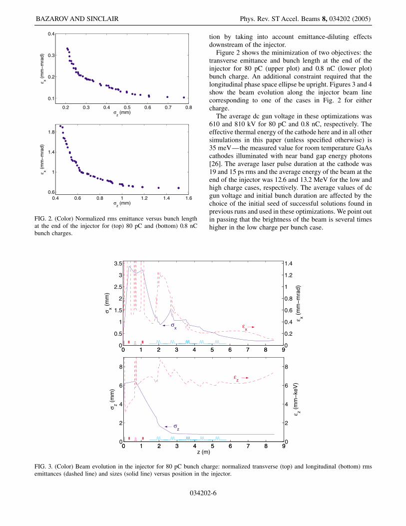
FIG. 3. (Color) Beam evolution in the injector for 80 pC bunch chaemittances (dashed line) and sizes (solid line) versus position in the
0.2 0.3 0.4 0.5 0.6 0.7 0.8
0.1
0.2
0.3
0.4
σz (mm)
ε x (m
m−
mra
d)
0.4 0.6 0.8 1 1.2 1.4 1.60.6
1
1.4
1.8
σz (mm)
ε x (m
m−
mra
d)
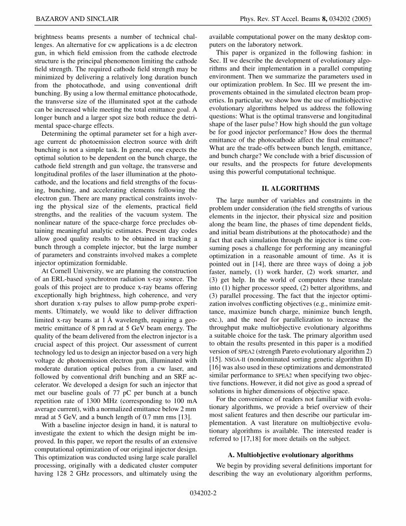
FIG. 2. (Color) Normalized rms emittance versus bunch lengthat the end of the injector for (top) 80 pC and (bottom) 0.8 nCbunch charges.
BAZAROV AND SINCLAIR Phys. Rev. ST Accel. Beams 8, 034202 (2005)
03420
tion by taking into account emittance-diluting effectsdownstream of the injector.
Figure 2 shows the minimization of two objectives: thetransverse emittance and bunch length at the end of theinjector for 80 pC (upper plot) and 0.8 nC (lower plot)bunch charge. An additional constraint required that thelongitudinal phase space ellipse be upright. Figures 3 and 4show the beam evolution along the injector beam linecorresponding to one of the cases in Fig. 2 for eithercharge.
The average dc gun voltage in these optimizations was610 and 810 kV for 80 pC and 0.8 nC, respectively. Theeffective thermal energy of the cathode here and in all othersimulations in this paper (unless specified otherwise) is35 meV—the measured value for room temperature GaAscathodes illuminated with near band gap energy photons[26]. The average laser pulse duration at the cathode was19 and 15 ps rms and the average energy of the beam at theend of the injector was 12.6 and 13.2 MeV for the low andhigh charge cases, respectively. The average values of dcgun voltage and initial bunch duration are affected by thechoice of the initial seed of successful solutions found inprevious runs and used in these optimizations. We point outin passing that the brightness of the beam is several timeshigher in the low charge per bunch case.
5 6 7 8 95 6 7 8 90
0.2
0.4
0.6
0.8
1
1.2
1.4
ε x (m
m−
mra
d)
εx
5 6 7 8 95 6 7 8 90
2
4
6
8
)
ε z (m
m−
keV
)
εz
rge: normalized transverse (top) and longitudinal (bottom) rmsinjector.
2-6

0 1 2 3 4 5 6 7 8 90
1
2
3
4
5
6
σ x (m
m)
0 1 2 3 4 5 6 7 8 90
1
2
3
4
5
6
ε x (m
m−
mra
d)
εx
σx
0 1 2 3 4 5 6 7 8 90
1
2
3
4
5
6
z (m)
σ z (m
m)
0 1 2 3 4 5 6 7 8 90
10
20
30
40
50
60
ε z (m
m−
keV
)
σz ε
z
FIG. 4. (Color) Beam evolution in the injector for 0.8 nC bunch charge: normalized transverse (top) and longitudinal (bottom) rmsemittances (dashed line) and sizes (solid line) versus position in the injector.
MULTIVARIATE OPTIMIZATION OF A HIGH . . . Phys. Rev. ST Accel. Beams 8, 034202 (2005)
The beam evolution through the injector exhibits severalinteresting features [27]. While the bunch downstream ofthe dc gun has a nearly symmetrical ellipsoidal shape,during compression the bunch begins to develop a tear-droplike shape with a more tightly focused tail. After thebeam exits the cryomodule, the slice emittances in thelarger diameter region of the bunch are aligned but aremismatched with those in the bunch tail. The final align-ment of the slice emittances takes place in the drift regionfollowing the cryomodule.
B. Gun voltage
It is widely believed that a very high gun voltage andelectric field at the photocathode is critical to achievinggood beam properties. We carried out a two-objectiveoptimization, in which a minimum transverse emittancewas sought while the gun voltage was being minimized atthe same time. The cathode-anode geometry was kept fixedduring this optimization, so an increased gun voltage re-sults in a similarly increased cathode electric field strength.An additional constraint picked only those solutions thathad the rms bunch length at the end of the injector less than
03420
0.9 mm. The resulting nondominated front is shown inFig. 5.
The longitudinal electric field on the axis of the gun isshown in Fig. 6. The gun has a 25 angle Pierce-likecathode electrode to provide transverse focusing.
The gaps in Fig. 5 (upper plot) are algorithm specific andreflect the following fact. Optimum values of most decisionvariables depend strongly on the gun voltage, and a goodspread in this objective (i.e., the voltage) implies a similarspread in the decision space. On the other hand, crossingoperators work best when a successful offspring does notdiffer dramatically from the parents, thus making it diffi-cult for the algorithm to uniformly fill the objective space.To reduce this effect one has to increase the population sizeand the number of generations.
The salient feature of Fig. 5 is clear—a higher gunvoltage is important to obtain low emittance only up to acertain point, after which the dependence on gun voltage isrelatively small. We note that the gun voltage required toobtain small emittances is well within the specifications ofour injector system. Our injector will use a gun voltagebetween 500 and 750 kV, which is above the values pres-ently achieved with dc photoemission guns. We have in-
2-7

300 400 500 600 700 800 9000.05
0.1
0.15
0.2
0.25
Vgun
(kV)
ε x (m
m−
mra
d)
420 430 440 450 460 470 480 490 5000.6
0.8
1
1.2
1.4
1.6
1.8
2
Vgun
(kV)
ε x (m
m−
mra
d)
FIG. 5. (Color) Normalized rms emittance versus voltage in the gun for (top) 80 pC and (bottom) 0.8 nC bunch charges. The averagebunch length corresponding to these calculations was (top) 0.8 mm and (bottom) 0.9 mm.
0 2 4 6 8 100
2
4
6
8
10
12
14
16
18
z (cm)
Ez (
MV
/m)
FIG. 6. (Color) Axial electric field in the dc gun for 750 kVvoltage.
BAZAROV AND SINCLAIR Phys. Rev. ST Accel. Beams 8, 034202 (2005)
03420
creased the physical electrode dimensions over those in usewith the Jefferson Lab gun [7] to make operation at 500 kVcomparable to their present operation at 350 kV. In addi-tion, we anticipate using dielectric coatings on the elec-trode surfaces to greatly reduce field emission, which is theprimary limiting phenomenon in very high voltage guns[28].
It is interesting to observe that the thermal emittance inFig. 5 on average accounts for 77% and 58% of the finalemittance for 80 pC and 0.8 nC bunch charges, respectively(cf. Sec. III D).
It is important to point out, however, that the optimizeddistances between the elements before the cryomodule arerather crowded at lower gun voltages. For example, thedistance from the photocathode to the center of the firstSRF cavity is only 1.25 m for 80 pC at 300 kV gun voltage.The spacing of the elements becomes more relaxed in analmost linear fashion as the gun voltage is increased, e.g.,the same distance to the first SRF cavity is 2.3 m for850 kV.
2-8

MULTIVARIATE OPTIMIZATION OF A HIGH . . . Phys. Rev. ST Accel. Beams 8, 034202 (2005)
C. Optimal initial distribution
Proper shaping of the laser pulse illuminating the photo-cathode, both transversely and longitudinally, is known tobe important for obtaining a minimum emittance [29–31].While basic considerations might lead one to believe thatthe desired electron distribution should make the space-charge forces linear, the fact that the bunch evolves in anonlinear fashion in the nonrelativistic region near thecathode under the influence of the image space charge,and during drift bunching downstream of the bunchingcavity, make it difficult to predict the optimal shape ofthe laser distribution incident on the photocathode. On theother hand, the question is well posed for optimizationsuch as we perform in this study.
Six decision variables over the interval �0; 1� specifiedthe transverse and longitudinal laser profiles, viz., a tailparameter specified the fraction of the total width of theprofile occupied by tails as opposed to a flattop region(0 corresponding to uniform, and 1 to Gaussian shapes);a dip parameter allowed creating profiles depleted in thecenter; and an additional shape parameter, which, when setto 1 corresponds to a half-circle or, when set to 0, corre-sponds to a top hat. The full profile is obtained by multi-plication of the three respective parts.
Figure 7 shows typical optimum longitudinal and trans-verse profiles obtained from an emittance minimization forthe two charge cases. It is interesting to note the centraldepletion region in the longitudinal profile for the 80 pCcase and the fact that the transverse profile is intermediatebetween elliptical and flattop shapes in both cases.
Of the two profiles, the longitudinal shape is technicallythe more difficult to produce. Figures 8 and 9 show thesensitivity of the emittance to the tail parameter of thelongitudinal distribution for the 80 pC and 0.8 nC bunchcharge cases, respectively. The final bunch length wasabout 0.9 mm for both cases. The solid line shows theemittance change as the longitudinal profile is changed
transverselongitudinal
FIG. 7. (Color) Initial distribution profiles corresponding to minimum0.8 nC cases.
03420
with all other parameters in the injector kept fixed. Thetwo arrows indicate the minimum emittance values ob-tained with flattop transverse and longitudinal profiles,and with a flattop longitudinal profile and the transverseshape shown in Fig. 7. The data points show the minimumemittance obtained after the injector settings were opti-mized for each particular longitudinal tail parameter value.These results show that while there are longitudinal andtransverse distributions at the photocathode that produce aminimum emittance, different injector settings can givesimilarly small emittances until the longitudinal tails be-come quite significant. Similar results are expected fordeviations from the transverse profile that gives a mini-mum emittance.
D. Thermal energy of the photocathode
The choice of the most suitable photocathode involvesmany important considerations, such as the cathode opera-tional longevity, its sensitivity to the vacuum environment,its temporal response, and the effective thermal energy ofelectron distribution leaving the cathode. The latter pa-rameter combined with the transverse size of the illumi-nated area on the photocathode determines the minimumtransverse emittance.
Figure 10 shows the emittance from our injector as afunction of the effective thermal energy at the photoca-thode. The bunch length was constrained to be less than0.9 mm in these results. The gun voltage varied between607 and 622 kV for the lower charge and between 808 and847 kV for the higher charge per bunch. These simulationsemphasize the importance of the effective thermal energyof the photocathode to the ultimate beam brightness. Inparticular, it is often stated that in the case of a large chargeper bunch, where the emittance is dominated by space-charge effects, the thermal emittance from the photoca-thode is unimportant. These results clearly show this state-ment is not so. The underlying reason is that a smaller
transverselongitudinal
emittance at the end of the injector for (left) 80 pC and (right)
2-9

0 0.2 0.4 0.6 0.8 10
0.1
0.2
0.3
0.4
0.5
tail parameterε x (
mm
−m
rad)
both uniform
long. uniform
0.10.50.70.80.91.0
FIG. 8. (Color) 80 pC: emittance sensitivity (solid curve) to the longitudinal profile changes (top) and the corresponding profile shapes(bottom). Data points show the minimum normalized rms emittance obtained after the injector settings were reoptimized for eachparticular longitudinal tail parameter value.
0 0.2 0.4 0.6 0.8 10
1
2
3
4
5
tail parameter
ε x (m
m−
mra
d)
both uniform
long. uniform
0.10.50.70.80.91.0
FIG. 9. (Color) 0.8 nC: emittance sensitivity (solid curve) to the longitudinal profile changes (top) and the corresponding profile shapes(bottom). Data points show the minimum normalized rms emittance obtained after the injector settings were reoptimized for eachparticular longitudinal tail parameter value.
BAZAROV AND SINCLAIR Phys. Rev. ST Accel. Beams 8, 034202 (2005)
034202-10

0 50 100 150 200 250 3000.05
0.1
0.15
0.2
0.25
Etherm
(meV)ε x (
mm
−m
rad)
0 50 100 150 200 250 3000.4
0.6
0.8
1
1.2
1.4
1.6
Etherm
(meV)
ε x (m
m−
mra
d)
FIG. 10. (Color) The minimum transverse normalized rms emittance from injector as a function of the effective thermal energy fromthe photocathode for (top) 80 pC and (bottom) 0.8 nC bunch charge, respectively.
0.2 0.4 0.6 0.8 1 1.2 1.4 1.6 1.8
0.1
0.2
0.3
0.4
0.5
0.6
0.7
0.8
0.9
1
σz (mm)
ε x (m
m−
mra
d)
0.10.1
0.1
0.20.2
0.2
0.30.3
0.3
0.40.4
0.4
0.50.5
0.5
0.60.6
0.6
0.70.7
0.7
0.8
0.8
0.8
0.9
0.9
FIG. 11. (Color) Transverse normalized rms emittance versusbunch length for various charges in the injector (nC).
MULTIVARIATE OPTIMIZATION OF A HIGH . . . Phys. Rev. ST Accel. Beams 8, 034202 (2005)
effective thermal energy allows the illuminated spot size atthe photocathode to be larger, reducing the effects of spacecharge.
E. Emittance versus bunch length versus charge
Choosing the optimal parameters for an injector deliver-ing a particular charge per bunch is a complex task. Oftenthe exact trade-offs affecting the final beam quality are notknown, and frequently (as in the case of an injector for anERL light source) the beam quality requirements dependon the particular application. Knowing the Pareto-optimalfront provides one with invaluable information for choos-ing those injector parameters that will be fixed by design,and provides guidance for selecting those parameters thatare variable.
We performed multivariate optimizations of our injectordesign with three objectives: emittance minimization,bunch length minimization, and bunch charge maximiza-tion. The result of these optimizations is shown in Fig. 11.The population size for this optimization had to be in-creased because of higher dimensionality of the problem(3 objective functions). The optimization required a total ofabout 105 injector simulations. The data in Fig. 11 can bewell approximated by �x � q�0:73� 0:15=�2:3
z �, where �xis in mm mrad, q is the bunch charge in nC, and �z is therms bunch length in mm. Figure 12 shows the longitudinalemittance for the same data.
034202
In these optimizations the positions of various elementswere allowed to change (with the shortest distance betweenthe photocathode and the first SRF cavity limited to no lessthan 1 m). The general tendency is that for higher chargeper bunch the optimal beam element locations move closerto the gun and the spot size at the photocathode increases,as can be intuitively expected, to minimize space-charge
-11

0.2 0.4 0.6 0.8 1 1.2 1.4 1.6 1.8
10
20
30
40
50
60
σz (mm)
ε z (m
m−
keV
)
0.10.2
0.20.3
0.3 0.4
0.4 0.5
0.50.6
0.6
0.7
0.7
0.8
0.8
0.9
0.9
FIG. 12. (Color) Longitudinal rms emittance versus bunchlength for various charges in the injector (nC).
TABLE I. Comparison of the injector parameters between [13]and this work.
Parameter Ref. [13] This work Units
Charge 80 80 pCLaser spot size (rms) 0.6 0.3 mmLaser pulse duration (rms) 20 11 psdc gun voltage 500 750 kVBuncher voltage 116 126 kVSRF cavity 1 gradient 9.8 5.5 MV=mSRF cavities 2–5 gradient 7.2 10.6 MV=mSRF cavity 1 phase 10 43
Solenoid 1 peak field 0.058 0.077 TSolenoid 2 peak field 0.040 0.043 TSolenoid 1 position 0.29 0.26 mSolenoid 2 position 1.00 1.12 mBuncher position 0.80 0.57 mSRF cavity 1 position 1.80 1.90 m
Transverse emittance (rms) 0.82 0.14 mm mradBunch length (rms) 0.80 0.78 mmLongitudinal emittance (rms) 8.7 6.2 mm keVKinetic energy 10.6 12.6 MeV
BAZAROV AND SINCLAIR Phys. Rev. ST Accel. Beams 8, 034202 (2005)
effects at low energy. When the positions were kept fixedat the locations corresponding to the best emittancevalues for 0.1 nC (the distance to the first SRF cavityis 1.9 m) and the gun voltage was fixed to the designmaximum value of 750 kV, the optimizer nonethelesswas able to find good solutions for higher bunch charges.The emittances obtained were at most only about 30%larger than in the case where these elements were allowedto move. This suggests that the injector should performwell over a wide range of charge per bunch with fixedelement locations.
IV. DISCUSSION AND OUTLOOK
It is interesting to point out several salient features ofoptimized injector settings. It is intuitive that the optimizerwould seek to minimize contributions to the final emittancecoming from the three major sources: thermal energy of thephotocathode, space charge, and rf fields.
Table I provides a comparison between the parametersof the original injector design reported earlier in [13] andthis work. The electric field distribution in the gun isdifferent in the two cases, and the anode-cathode gap issmaller by 40% in this work. The laser distribution used in[13] was a temporal Gaussian, and a � � 15 Fermi-Diracshape transversely, while the present work has the opti-mum distributions found. In comparing the two sets ofinjector parameters, we see that the illuminated spot onthe cathode is smaller and the laser pulse duration is shorterin the present case. The focusing provided by the cathodeelectrode in the gun and by the first solenoid is stronger.Finally, the first superconducting cavity is operated atlower gradient, and well off crest in the bunching direction.This latter change reduces the rf emittance degradationfrom the first cavity, and results in a more adiabatic bunch-
034202
ing through the injector. Overall, there is no single im-provement factor which stands out as the major reason forthe reduced emittance.
As one might expect, the optimization produces a pro-nounced beam waist at the center of the first acceleratingcavity, while the beam size at the buncher cavity is larger.The rf emittance contribution from the buncher cavity iscomparable to, though smaller than, the contribution fromthe first accelerating cavity. In our optimization, we forcedthe last four accelerating cavities to have identical gra-dients and fixed phases with respect to each other. Thus,these last four cavities are operated very close to on crest.One can speculate that slightly better performance mightbe obtained by allowing these cavities to have independentgradients and phases to allow the bunching to be even moregentle.
The energy at the end of the injector is still relativelylow, and the projected emittance is not fully degenerate atthe location we have defined to be the ‘‘end’’ of theinjector. Careful matching to the following acceleratorsection will be important to preserve the low emittancethese simulations show to be possible from the injector.
Our optimizations demonstrate that an injector based ondrift bunching of the beam from a photoemission cathodein a dc gun is an excellent choice to achieve a very highbrightness, high average current electron beam. Excellentbeam quality is available from this injector over a broadrange of bunch charge. These optimizations further dem-onstrate that the thermal emittance available from thephotocathode is important at all bunch charges. This makesthe use of a negative electron affinity (NEA) photocathode,with its very low thermal emittance, an important advan-
-12

MULTIVARIATE OPTIMIZATION OF A HIGH . . . Phys. Rev. ST Accel. Beams 8, 034202 (2005)
tage. By cooling the negative electron affinity photoca-thode to liquid nitrogen temperatures, it should be possibleto improve the beam emittance for a given bunch chargeeven further [32]. The interplay between the spot size at thephotocathode, the thermal emittance, and the unrecover-able degradation from space-charge effects in the regionimmediately following the photocathode is complex, andnot amenable to analytic calculations or estimates. It ishere that the optimization calculation may lead to betterresults by exploring operating parameters that could other-wise be missed. The use of a dc gun allows a relatively longduration pulse from the photocathode, while the use of alow thermal emittance NEA photocathode may result in alarger optimum illuminated spot size at the cathode for agiven final emittance. The longer pulse and larger spot sizemay reduce the degradation from the strong space-chargeeffects close to the photocathode. The temporal response ofNEA photocathodes depends on the thickness of the cath-ode and the illumination wavelength and is long comparedto the temporal response of alkali antimonide and alkalitelluride photocathodes. The values for the temporal re-sponse from this optimization are comparable to thosereported for bulk GaAs [33], but it will be necessary toexplore these parameters experimentally to be fully con-fident in the results.
The injector design we have optimized employs practi-cal field strengths for all elements, and has specificallyincorporated realistic physical constraints to allow thevacuum system to be assembled, and to account for thetransition between room temperature and the 2 K environ-ment of the superconducting cavities. We have examinedthe sensitivity of the final emittance and bunch length tothe strengths and locations of the various elements, andfind that no unrealistic tolerances are required. The opti-mization is quite robust, in that when we have constrainedvarious parameters, such as the physical separation of keyelements, or moved away from the optimum laser profile atthe photocathode, we have been able to reoptimize andobtain results generally close to those of the originaloptimization.
A question that can be raised with regard to the resultspresented here is whether the optimum solutions can bereproduced with another space-charge code. This questionbears on the more significant issue of the accuracy of theavailable space-charge codes. Any optimization can onlybe as good as the model that is being used to evaluate theobjectives. To address this issue in a very limited fashionwe have compared several of our optimal solutions withresults from PARMELA [34]. All of the variable parametersand the field maps corresponding to our optimal perform-ance simulated with ASTRA tracking were directly intro-duced into PARMELA input files. We find that the agreementin transverse emittance is better than a factor of 2 for allthese cases. We believe that much of the remaining differ-ence can be attributed to slight differences in the way the
034202
two codes treat field maps and perform the meshing for thespace-charge calculation.
Based on these optimizations, we believe this injectordesign is an excellent choice for an ERL-based synchrotronlight source to produce very high fluxes of coherent hardx rays, and to provide ultrashort x-ray pulses. The x-raybeam characteristics that will be made available from sucha light source are vastly superior to those from the bestexisting or planned storage ring sources. With the properphotocathode and laser choices, this injector will providebeams of highly polarized electrons for potential applica-tions in a linac-ring version of an electron-ion collider, or,perhaps, for the linear collider.
Quite apart from the optimization of the injector re-ported here, we have demonstrated the great utility ofmultiobjective optimization algorithms, implemented in aparallel computing environment, to address complex ac-celerator physics and engineering challenges. By combin-ing parallelized versions of these algorithms with ‘‘front-to-end’’ simulations of a full accelerator, one can obtain thePareto-optimal front of the most relevant quantities (e.g.,brilliance, luminosity, bunch charge, etc.) [35]. This is adramatic advantage over a ‘‘single-point’’ design, in whichimportant decision variables (e.g., bunch charge) are keptfixed from the outset. We are constructing the injectordescribed here at Cornell University, and will be able tobenchmark the results of these optimizations with realbeam measurements in the foreseeable future.
ACKNOWLEDGMENTS
We acknowledge MacCHESS for granting us access totheir two computer clusters, which were used extensivelyin this work. In particular, we thank Sol Gruner, Quan Hao,Ernie Fontes, and Frank Labonte of CHESS for their sup-port and assistance. We thank the LEPP computer groupand acknowledge our numerous CLEO and LEPP col-leagues who have tolerated our using their theoreticallylatent desktop computers as a parallel processing resource.Igor Senderovich has written the ‘‘quiet start’’ generator ofthe initial particle distribution, as well as implementedvarious metrics to characterize performance of differentevolutionary algorithms. This work is supported by CornellUniversity.
-13
[1] G. R. Neil et al., Phys. Rev. Lett. 84, 662 (2000).[2] B. Aune et al., Phys. Rev. ST Accel. Beams 3, 092001
(2000).[3] C. Reece, in Proceedings of the 10th Workshop on RF
Superconductivity, 2001, Tsukuba City, Japan, http://con-ference.kek.jp/SRF2001/
[4] I. Ben-Zvi et al., in Proceedings of the 2003Particle Accelerator Conference, Portland, OR (IEEE,Piscataway, NJ, 2003), pp. 39–41.

BAZAROV AND SINCLAIR Phys. Rev. ST Accel. Beams 8, 034202 (2005)
[5] Y. S. Derbenev et al., in Proceedings of the 2004 EuropeanParticle Accelerator Conference, Lucerne (EPS-AG,Lucerne, 2004), pp. 893–895.
[6] S. M. Gruner et al., Rev. Sci. Instrum. 73, 1402 (2002).[7] S. Benson et al., in Proceedings of the 26th International
FEL Conference, Trieste, 2004 (Comitato ConferenzeElettra, Trieste, 2004), pp. 229–232.
[8] D. H. Dowell et al., Appl. Phys. Lett. 63, 2035 (1993).[9] B. E. Carlsten, Nucl. Instrum. Methods Phys. Res., Sect. A
285, 313 (1989).[10] J. Teichert et al., in Proceedings of the 2004 European
Particle Accelerator Conference, Lucerne (Ref. [5]),pp. 333–335.
[11] A. Michalke et al., in Proceedings of the 1992 EuropeanParticle Accelerator Conference, Berlin (World Scientific,Singapore, 1992), pp. 1014–1017.
[12] D. Janssen et al., Nucl. Instrum. Methods Phys. Res.,Sect. A 507, 314 (2003).
[13] I. Bazarov and C. Sinclair, in Proceedings of the 2003Particle Accelerator Conference, Portland, OR (Ref. [4]),pp. 2062–2064.
[14] G. F. Pfister, In Search of Clusters (Prentice-Hall, NJ,1998).
[15] E. Zitzler et al., Swiss Federal Institute of Technology(ETH) Technical Report No. 103, 2001.
[16] K. Deb et al., IEEE Trans. Evolut. Comput. 6, 182(2002).
[17] K. Deb, Multi-Objective Optimization using EvolutionaryAlgorithms (Wiley, Chichester, 2001).
[18] C. A. C. Coello, D. A. V. Veldhuizen, and G. B. Lamont,Evolutionary Algorithms for Solving Multi-ObjectiveProblems (Kluwer Academic/Plenum, New York, 2002).
[19] S. Bleuler, M. Laumanns, L. Thiele, and E. Zitzler, inEvolutionary Multi-Criterion Optimization (EMO 2003),edited by C. M. Fonseca, P. J. Fleming, E. Zitzler, K. Deb,and L. Thiele, Lecture Notes in Computer ScienceVol. 2632/2003 (Springer-Verlag, Heidelberg, 2003),pp. 494–508.
034202
[20] K. Flottmann, ASTRA: A Space Charge Tracking Algorithm,http://www.desy.de/ mpyflo/Astra_dokumentation/
[21] V. Shemelin et al., in Proceedings of the 2003 ParticleAccelerator Conference, Portland, OR (Ref. [4]),pp. 2059–2061.
[22] H. Padamsee et al., in Proceedings of the 2004 EuropeanParticle Accelerator Conference, Lucerne (Ref. [5]),pp. 491–493.
[23] J. Billen and L. Young, Los Alamos Laboratory TechnicalReport No. LA-UR-96-1834, 2000.
[24] D. Myakishev and V. Yakovlev, in Proceedings of the1995 Particle Accelerator Conference, Dallas (IEEE,Piscataway, NJ, 1995), pp. 2348–2350.
[25] I. Bazarov and G. Hoffstaetter, in Proceedings of the 2003Particle Accelerator Conference, Portland, OR (Ref. [4]),pp. 842–844.
[26] B. M. Dunham et al., in Proceedings of the 1995 ParticleAccelerator Conference, Dallas (Ref. [24]), pp. 1030–1032.
[27] Animation of the beam motion in our injector is availableat http://www.lepp.cornell.edu/~ib38/injector
[28] C. Sinclair et al., in Proceedings of the 2001 ParticleAccelerator Conference, Chicago (IEEE, Piscataway, NJ,2001), pp. 610–612.
[29] F. Zhou et al., Phys. Rev. ST Accel. Beams 5, 094203(2002).
[30] H. Tomizawa et al., in Proceedings of the 2002 EuropeanParticle Accelerator Conference, Paris (EPS-IGA andCERN, Geneva, 2002), pp. 1819–1821.
[31] J. Yang et al., J. Appl. Phys. 92, 1608 (2002).[32] D. Orlov et al., Nucl. Instrum. Methods Phys. Res.,
Sect. A 532, 418 (2004).[33] A. V. Aleksandrov et al., Phys. Rev. E 51, 1449 (1995).[34] J. Billen and L. Young, Los Alamos Laboratory Technical
Report No. LA-UR-96-1835, 2000.[35] I. Bazarov and H. Padamsee, LEPP, Cornell University
Technical Report No. CBN 05-3, 2005.
-14


![X-one-クレイパックリーフ-単 EX INUI) EX INI]PEX INUPEX Brightness Clay Pack for your brightness life íNUP Brightness Clay Pack far your brightness life íNUP](https://img.dokumen.tips/doc/110x75/5c8b11e009d3f2d5658ce1da/x-one-ex-inui-ex-inipex-inupex-brightness-clay.jpg)