Embed Size (px)
Citation preview
HELSINKI UNIVERSITY OF TECHNOLOGYSignal Processing LaboratorySMARAD Centre of Excellence
Multiuser Detection for SDMA OFDM
S7233-Postgraduate CourseFernando Gregorio

12/8/2004 Fernando GregorioS72-333 – Multiuser Detection
2
HELSINKI UNIVERSITY OF TECHNOLOGYSignal Processing LaboratorySMARAD Centre of Excellence
• Smart Antenna applications– Beamforming– Spatial Diversity Systems– Space Division Multiple Access (SDMA)
12/8/2004 Fernando GregorioS72-333 – Multiuser Detection
3
HELSINKI UNIVERSITY OF TECHNOLOGYSignal Processing LaboratorySMARAD Centre of Excellence
• Space Division Multiple Access (SDMA)– L different users– User-specific spatial signature– The signal signature generated by the
channel over the transmitted signal acts like spreading code in a CDMA system.
– Multiuser detection techniques known from CDMA can be applied in SDMA-OFDM
12/8/2004 Fernando GregorioS72-333 – Multiuser Detection
4
HELSINKI UNIVERSITY OF TECHNOLOGYSignal Processing LaboratorySMARAD Centre of Excellence
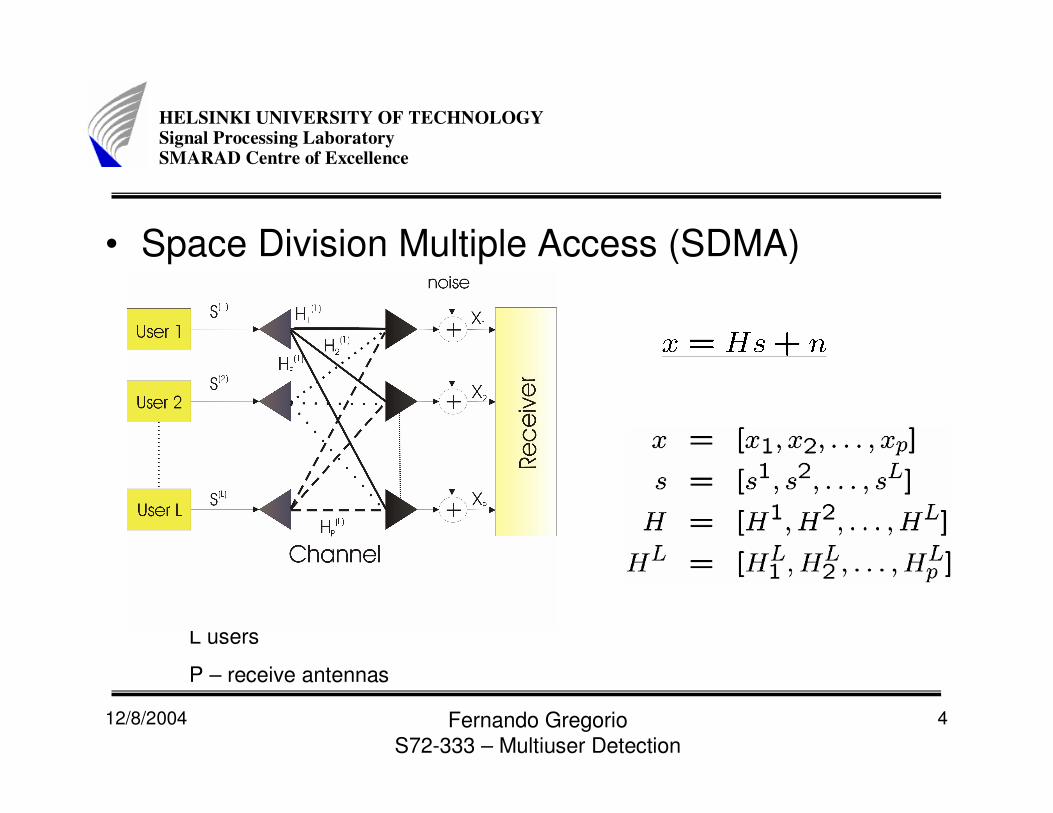
• Space Division Multiple Access (SDMA)
L users
P – receive antennas

12/8/2004 Fernando GregorioS72-333 – Multiuser Detection
5
HELSINKI UNIVERSITY OF TECHNOLOGYSignal Processing LaboratorySMARAD Centre of Excellence
• Linear detection techniques– The different users
transmitted signals are estimated with the aid of a linear combiner.
– The residual interference caused by remaining users is neglected.
12/8/2004 Fernando GregorioS72-333 – Multiuser Detection
6
HELSINKI UNIVERSITY OF TECHNOLOGYSignal Processing LaboratorySMARAD Centre of Excellence
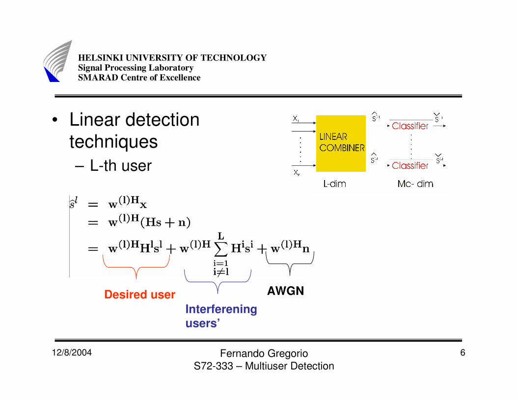
• Linear detection techniques– L-th user
Desired userInterferening users’
AWGN
12/8/2004 Fernando GregorioS72-333 – Multiuser Detection
7
HELSINKI UNIVERSITY OF TECHNOLOGYSignal Processing LaboratorySMARAD Centre of Excellence
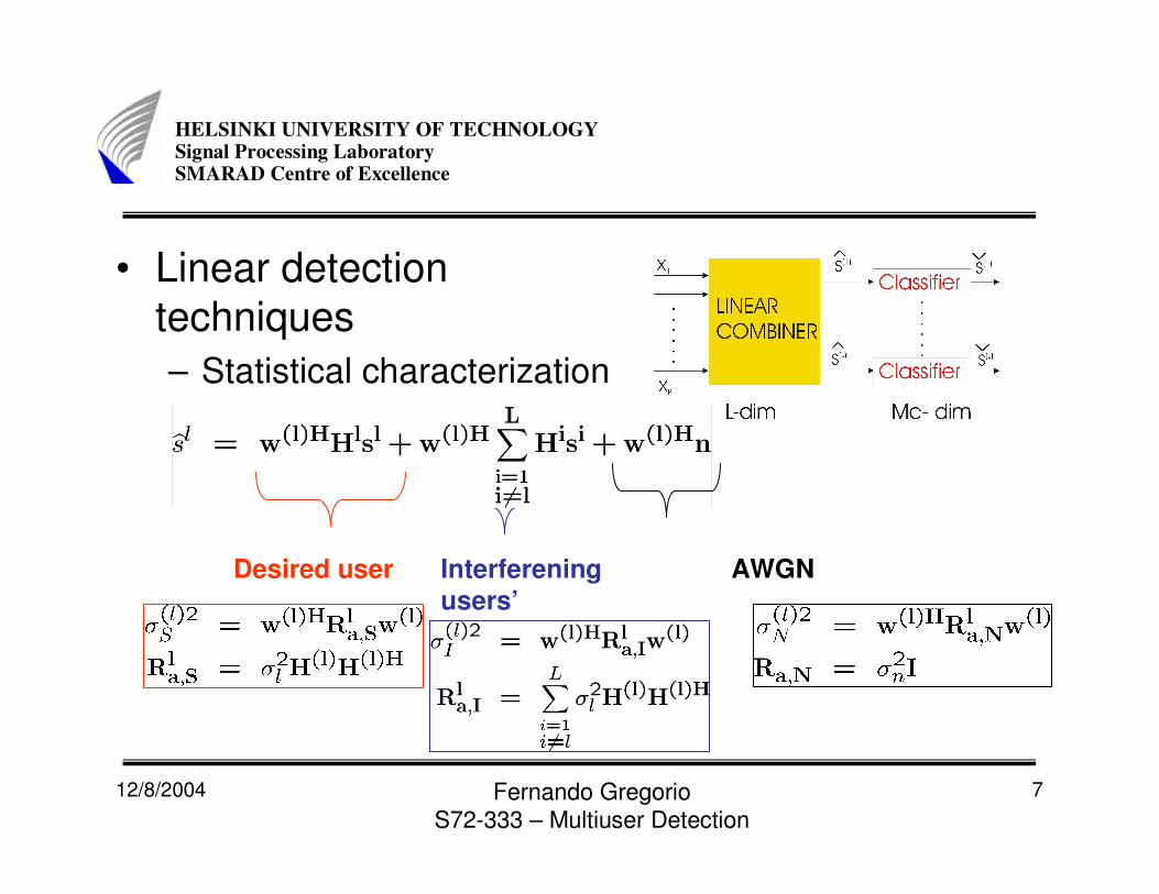
• Linear detection techniques– Statistical characterization
Desired user Interferening users’
AWGN
12/8/2004 Fernando GregorioS72-333 – Multiuser Detection
8
HELSINKI UNIVERSITY OF TECHNOLOGYSignal Processing LaboratorySMARAD Centre of Excellence
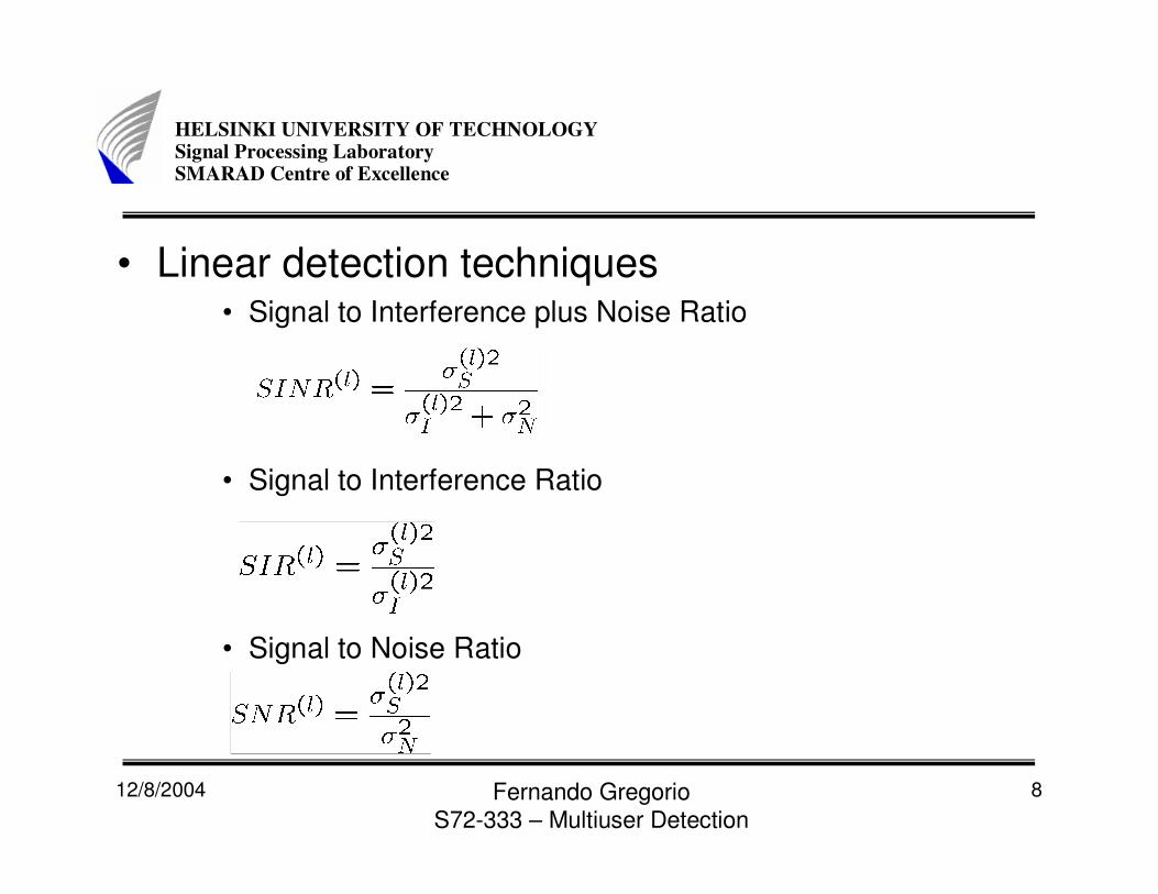
• Linear detection techniques• Signal to Interference plus Noise Ratio
• Signal to Interference Ratio
• Signal to Noise Ratio

12/8/2004 Fernando GregorioS72-333 – Multiuser Detection
9
HELSINKI UNIVERSITY OF TECHNOLOGYSignal Processing LaboratorySMARAD Centre of Excellence
• Linear detector
•Least Squares Error
•Zero Forcing
•Maximize SNR at the receiver
•Minimum squares Error
•Exploits the available statistical knowledge concerning the signals transmitted
12/8/2004 Fernando GregorioS72-333 – Multiuser Detection
10
HELSINKI UNIVERSITY OF TECHNOLOGYSignal Processing LaboratorySMARAD Centre of Excellence
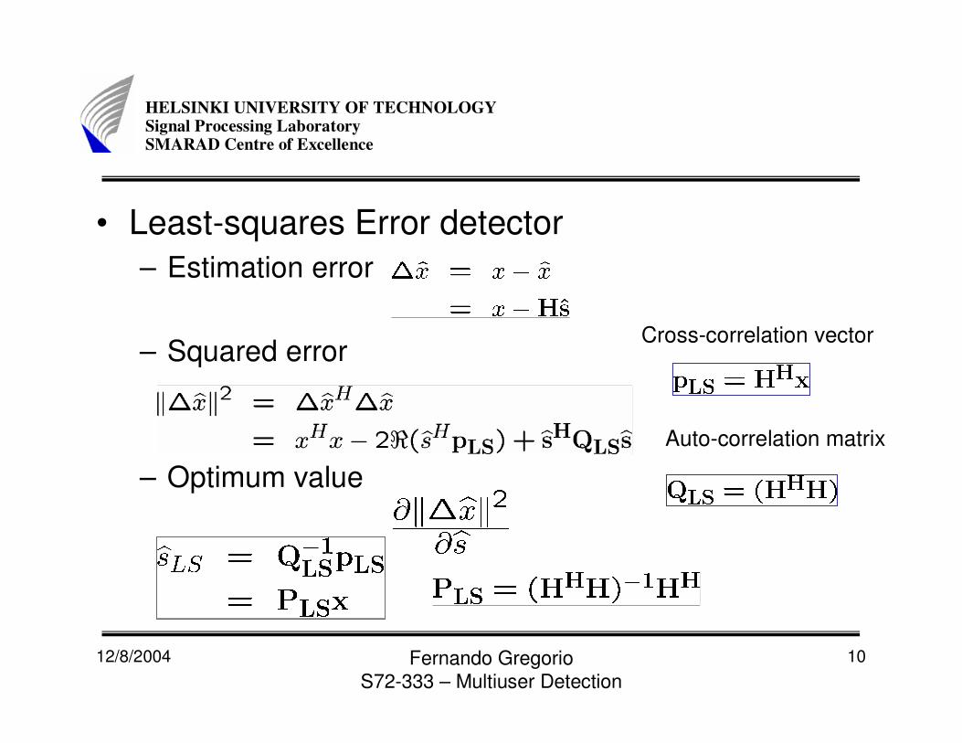
• Least-squares Error detector– Estimation error
– Squared error
– Optimum value
Cross-correlation vector
Auto-correlation matrix

12/8/2004 Fernando GregorioS72-333 – Multiuser Detection
11
HELSINKI UNIVERSITY OF TECHNOLOGYSignal Processing LaboratorySMARAD Centre of Excellence
• Least-squares Error detector
• The matrix PLS projects the vector x of the P different antenna elements' received signals onto the column space of the channel matrix H
Projection vector

12/8/2004 Fernando GregorioS72-333 – Multiuser Detection
12
HELSINKI UNIVERSITY OF TECHNOLOGYSignal Processing LaboratorySMARAD Centre of Excellence
• Minimum Mean squares error detector– Cost Function
– The estimation error’s autocorrelation matrix
12/8/2004 Fernando GregorioS72-333 – Multiuser Detection
13
HELSINKI UNIVERSITY OF TECHNOLOGYSignal Processing LaboratorySMARAD Centre of Excellence
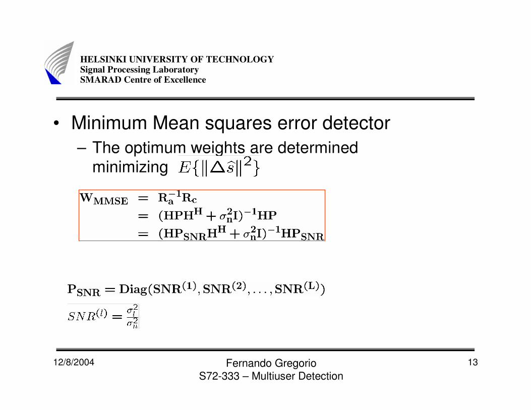
• Minimum Mean squares error detector– The optimum weights are determined
minimizing

12/8/2004 Fernando GregorioS72-333 – Multiuser Detection
14
HELSINKI UNIVERSITY OF TECHNOLOGYSignal Processing LaboratorySMARAD Centre of Excellence
• Minimum Variance (MV) combining– LS
• Information concerning with the AWGN process is not considered.
– MMSE• Balance between the recovery signals transmitted and the
suppression of the AWGN.
– MV• Recover the original signals while ensuring a partial
suppression of the AWGN.• The cost-function incorporates both a constraint on the
desired user’s effective transfer factor as well as theundesired signal’s variance.
12/8/2004 Fernando GregorioS72-333 – Multiuser Detection
15
HELSINKI UNIVERSITY OF TECHNOLOGYSignal Processing LaboratorySMARAD Centre of Excellence
• Non-Linear Detection– Linear detector assumes that the different
users’ associated linear combiner output are corrupted only by AWGN
– Linear combiner output signal contain residual interference which is not Gaussian distributed.
– LS and MMSE sequential structure.
12/8/2004 Fernando GregorioS72-333 – Multiuser Detection
16
HELSINKI UNIVERSITY OF TECHNOLOGYSignal Processing LaboratorySMARAD Centre of Excellence
• Non-Linear Detection– The operation of classification can be embedd
into the linear combination process.– The residual multi-user interference observed
at the classifier’s input is reduced– Successive Interference Cancellation (SIC)– Parallel Interference Cancellation (PIC)
12/8/2004 Fernando GregorioS72-333 – Multiuser Detection
17
HELSINKI UNIVERSITY OF TECHNOLOGYSignal Processing LaboratorySMARAD Centre of Excellence
• Successive Interference Cancellation (SIC)– Only the specific user having the highest SINR, SIR
or SNR in each iteration at the output of the LS or MMSE combiner is detected.
– Having detected this user’s signal, the correspondingdemodulated signal is subtracted from the composite
signal received by the different antenna elements.– New iteration.
12/8/2004 Fernando GregorioS72-333 – Multiuser Detection
18
HELSINKI UNIVERSITY OF TECHNOLOGYSignal Processing LaboratorySMARAD Centre of Excellence
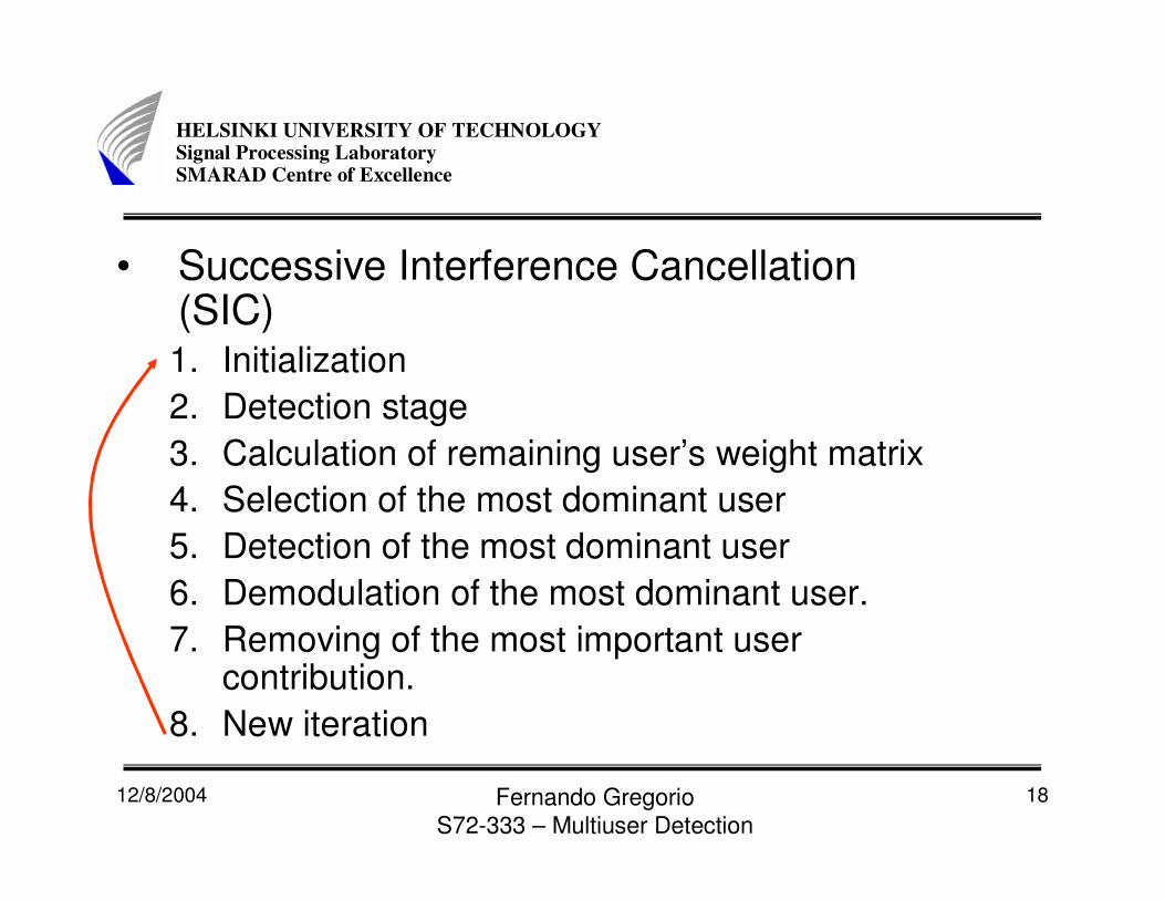
• Successive Interference Cancellation (SIC)1. Initialization2. Detection stage3. Calculation of remaining user’s weight matrix 4. Selection of the most dominant user5. Detection of the most dominant user6. Demodulation of the most dominant user.7. Removing of the most important user
contribution.8. New iteration
12/8/2004 Fernando GregorioS72-333 – Multiuser Detection
19
HELSINKI UNIVERSITY OF TECHNOLOGYSignal Processing LaboratorySMARAD Centre of Excellence
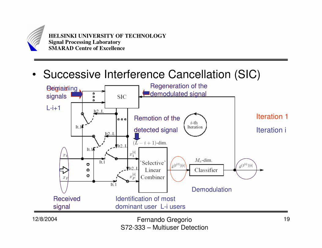
• Successive Interference Cancellation (SIC)
Received signal
Identification of most dominant user L-i users
Demodulation
Regeneration of the demodulated signal
Original signals
Remotion of the
detected signal
Iteration 1
Received signal
Regeneration of the demodulated signal
Remaining signals
L-i+1
Remotion of the
detected signal Iteration i

12/8/2004 Fernando GregorioS72-333 – Multiuser Detection
20
HELSINKI UNIVERSITY OF TECHNOLOGYSignal Processing LaboratorySMARAD Centre of Excellence
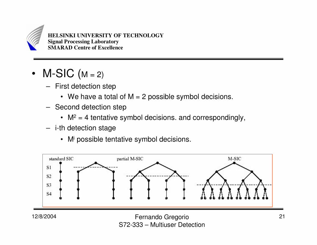
• M-Successive Interference Cancellation (SIC)– Error propagation problems in standard SIC.– MSIC-> Track from each detection stage not
only the single most likely symbol decision, but an increased number of M· Mc most likely tentative symbol decisions, where Mc denotes the number of constellation points associated with a specific modulation scheme.
12/8/2004 Fernando GregorioS72-333 – Multiuser Detection
21
HELSINKI UNIVERSITY OF TECHNOLOGYSignal Processing LaboratorySMARAD Centre of Excellence
• M-SIC (M = 2)– First detection step
• We have a total of M = 2 possible symbol decisions.– Second detection step
• M2 = 4 tentative symbol decisions. and correspondingly,– i-th detection stage
• Mi possible tentative symbol decisions.

12/8/2004 Fernando GregorioS72-333 – Multiuser Detection
22
HELSINKI UNIVERSITY OF TECHNOLOGYSignal Processing LaboratorySMARAD Centre of Excellence
• Partial M-SIC– The performance improvement potentially observed
for the M-SIC scheme compared tothe standard SIC arrangement is achieved at the cost of a significantly increased computational complexity.
– For sufficiently high SNRs the standard SIC detector’s performance is predetermined by the bit- or symbol-error probabilities incurred during the first detection stage.
– If the most dominant user’s associated symbol decision is erroneous, its effects potentially propagate to all other users’ decisions conducted in the following detection stages.

12/8/2004 Fernando GregorioS72-333 – Multiuser Detection
23
HELSINKI UNIVERSITY OF TECHNOLOGYSignal Processing LaboratorySMARAD Centre of Excellence
• Partial M-SIC– The symbol error probability specifically of the first
detection stage should be as low as possible.– The tentative symbol decisions carried out at later
detection stages become automatically more reliable as a result of the system’s increased diversity order due to removing the previously detected users.
– M > 1 number of tentative symbol decisions at each detection node are retained, characterized by its associated updated P-dimensional vector of received signals only up to the specific LpM-SIC-th stage in the detection process.
– At later detection stages only one symbol decision is retained, as in standard SIC scheme.
12/8/2004 Fernando GregorioS72-333 – Multiuser Detection
24
HELSINKI UNIVERSITY OF TECHNOLOGYSignal Processing LaboratorySMARAD Centre of Excellence
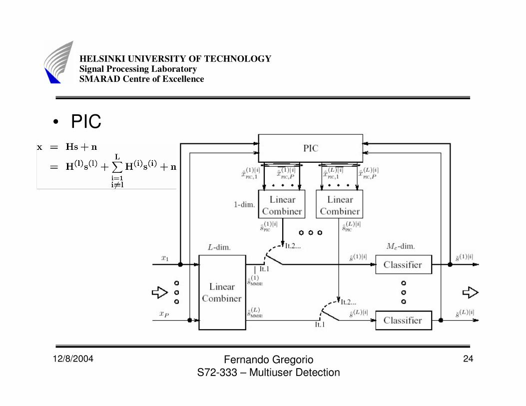
• PIC
12/8/2004 Fernando GregorioS72-333 – Multiuser Detection
25
HELSINKI UNIVERSITY OF TECHNOLOGYSignal Processing LaboratorySMARAD Centre of Excellence
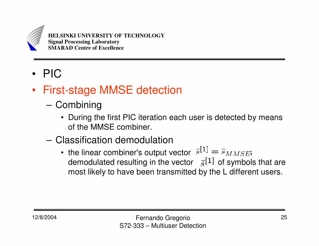
• PIC• First-stage MMSE detection
– Combining• During the first PIC iteration each user is detected by means
of the MMSE combiner.
– Classification demodulation• the linear combiner's output vector is
demodulated resulting in the vector of symbols that are most likely to have been transmitted by the L different users.
12/8/2004 Fernando GregorioS72-333 – Multiuser Detection
26
HELSINKI UNIVERSITY OF TECHNOLOGYSignal Processing LaboratorySMARAD Centre of Excellence
• PIC• i-th stage PIC detection (i>1)
– PIC• During the i-th PIC iteration a potentially improved estimate
of the complex symbol s(l) transmitted by the l-th user is obtained upon subtracting in a first step the L-1 interfering users' estimated signal contributions, from the original vector x of signals received by the different antenna elements
– Combining• Extract an estimate of the signal s(l) transmittedby the $l-th$ user from the l-th user's PIC-related array output
vector .
– Classification / demodulation• Delivers the symbol that is most likely to have been
transmitted by the l-th user.

12/8/2004 Fernando GregorioS72-333 – Multiuser Detection
27
HELSINKI UNIVERSITY OF TECHNOLOGYSignal Processing LaboratorySMARAD Centre of Excellence
• Maximum Likelihood detection
12/8/2004 Fernando GregorioS72-333 – Multiuser Detection
28
HELSINKI UNIVERSITY OF TECHNOLOGYSignal Processing LaboratorySMARAD Centre of Excellence
• Comparison– BER– Complexity


![Design and implementation of Haar wavelet packet ...Sep 05, 2018 · DCSK [8] and multiuser OFDM-based DCSK (MU Research Article Abstract Efficient design and implementation of Haar](https://img.dokumen.tips/doc/110x75/5fb251f9ec6a105ba269b811/design-and-implementation-of-haar-wavelet-packet-sep-05-2018-dcsk-8-and.jpg)