Embed Size (px)
Citation preview

104
4RUNNER (EM03M0U)
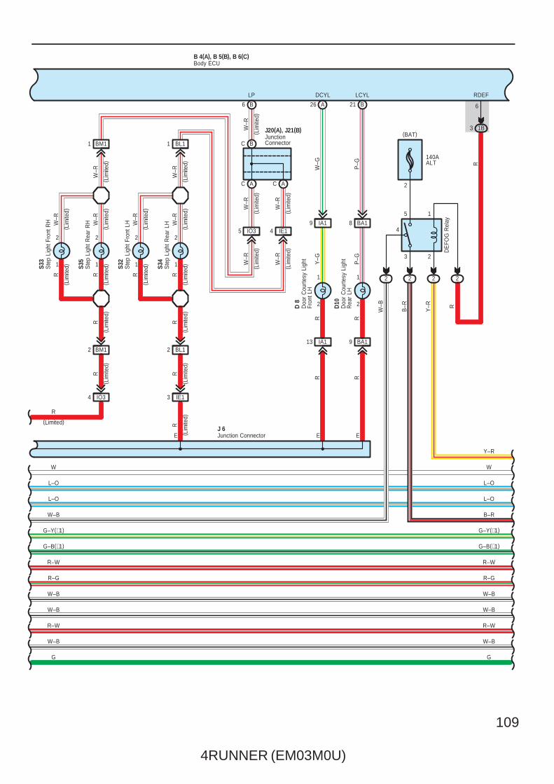
Multiplex Communication System – BEAN
20ADR/LCK
2
2
7. 5AACC
1E9
622 C12
ACC BDR1
B 4(A), B 5(B), B 6(C)
G–W
C21 4 C
A39
IG13 IG12 IG11
CLTB CLTE
CLTS
CLTS
CLTE
1
CLTB
3 4
L–Y
G–W Y
L–Y
G–W Y
50AJ/B
2
2
L–W
L–W
15ARRWSH 1
WIG
Automatic LightControl Sensor
Body ECU(BAT) (BAT) (ACC) (IG)
4RUNNER (EM03M0U)
105
R–W
R–B
L–W
L–W
TAIL
Rel
ay
TRLY
5 1
3 2
18
1 1C
B 4(A), B 5(B), B 6(C)
2
2
HRLY
2
W
1B8
C20
1 5
2 3
IC419
10AHEAD(LO LH)
10AHEAD(LO RH)
10AHEAD(HI LH)
10AHEAD(HI RH)
2
2
2
2
2
2 2 2
2
1111
1
2 2
1
2
1
IC422
EB
IC423
R–BW
2
HF2
R–G
B
HEADRelay
Battery
W–B
W–B
R–W
R–L
W
R–B
R–Y
R–G
17
R–G
R–W
W–B
W–B
R–W
R–B
W
R–B
H 2
W–B
H 4
H 1
Body ECU
Hea
dlig
ht L
H (
Hig
h)
Hea
dlig
ht L
H (
Low
)
Hea
dlig
ht R
H (
Low
)
R–L
R–L
106
4RUNNER (EM03M0U)
Multiplex Communication System – BEAN
IG
A
B 4(A), B 5(B), B 6(C)
OFF
Tail
Head
Auto
Low
High
Flash
OFF
ON
Ligh
tC
ontro
l SW
Dim
mer
SW
Fog
Ligh
tS
WIH19
B B
B A
711
E AE A E A
R–G
C7
D B
1
2
IN110
IH18
C8
IH11 IH110
C3C1
BA
BA
17
C12
J10(
A), J
11( B
)
W–B
8
H 3
1216141310
R–L
HEAD TAIL
R–W
A HF
W–B
W–B
J15(
B)
R–G
R–G
R–G
R–G
R–G
R–G
J12(A), J13(B)
R–G
R
W–B
W–B
G
R G
G–R
G–O
R–W
G–O
W–B
R–W
W–B
IC32
W–B
R–W
Body ECU
Combination SW
Hea
dlig
ht R
H (
Hig
h)
Junc
tion
Con
nect
or
JunctionConnector
Junc
tion
Con
nect
or
G–R
∗ 1 : w/ Daytime Running Light
2
LH
RH
Turn
SW
W–B
(∗1)
1 3
G–B(∗1)
G–Y(∗1)
G–B
G–Y
( ∗1)
( ∗1)
R–W
R–G
W–B
W–B
R–L
JunctionConnector
J 5
A
∗ 2 : w/ Rear Seat Entertainment System∗ 3 : w/o Rear Seat Entertainment System
4RUNNER (EM03M0U)
107
B 4(A), B 5(B), B 6(C)
1 3
2 5
2 2
FR FOGRelay
2 2
B
B 1
2
1
2
EA
15AFR FOG
2
R–W
W–B
W–B
W–B
LG
W–B
F 1
2
R–W
W–B
W–B
W–B
R–L
W–B
G G
W–B
W–B
W–B
W–B
F 2
M 5
8 1A7 1A
2 1H1 1A1 1H25 1J
3 2
5 1
2 1F
30APOWER
21
4
PO
WE
R R
elay
L
W–B
2
W
PWS
L–O
PWS
L–O
13
ILE
L–O
16
GND2
W
GND1
4
L–O
R–G R–G
Body ECU
Fron
t Fog
Lig
ht L
H
Fron
t Fog
Lig
ht R
H
J 3
Moo
n R
oof
Con
trol E
CU
G
W–B
G–R
G–B(∗1)
G–Y(∗1)
G–B(∗1)
G–Y(∗1)
G
W–B
Junc
tion
Con
nect
or
W–B
(BAT)(BAT)
IC312
GG
DO
OR
ON
OFF O
FFO
N
DO
OR
L 2
1
3 2
W
W
WW( ∗
2)W W
I20(
A), (
B)In
terio
r Li
ght
Lugg
age
Com
partm
ent
Ligh
t
B3A3
(∗3)B2(∗2)A2
(∗3)B1(∗2)A1
( ∗2)
( ∗2)
( ∗2)
( ∗2)
( ∗2)
W( ∗
3)
W( ∗
3) W(∗3)
W(∗3)
W(∗2)
W(∗3)
W(∗2)
W(∗3)
W(∗2)
W( ∗
3)
108
4RUNNER (EM03M0U)
Multiplex Communication System – BEAN
EUPDOWN
R–GR–G
L–O
W–B
G–Y(∗1)
G–B(∗1)
R–W
W–B
W–B
L–O
R–W
W–B
G–Y(∗1)
G–B(∗1)
R–W
W–B
W–B
W–B
R
W
W
WR
R
R
W–B W
J 6
R–G
B–Y
Y–RB–L
RR
D 9
Y L–R
B 1
( w/ V
anity
Lig
ht)
( w/ V
anity
Lig
ht)
L–R
(w/ Vanity Light)
Y
(w/ Vanity Light)
J35
R
V 7
BDN BUP COM PCYL
J12(
A), J
13( B
)
RCYL
V 6
E
P 7
1 1 1
R
6 3 1
I17
5 D112 2
BB1
22 BA25
89 IP1
9 BB11 IP2
1
2
1
2
B1910 B8 B
HHH
6
2
22 1J6 1E9 1A
4 1A 1A19
9 1K18 1A12 1A
H
R–W
B
E Back Door PowerWindow Control SW
Doo
r C
ourte
sy L
ight
Fron
t RH
Doo
r C
ourte
sy L
ight
Rea
r R
HIgni
tion
Key
Cyl
inde
r Li
ght
Junc
tion
Con
nect
or
Junction Connector
Junction ConnectorPer
sona
l Lig
ht
Van
ity L
ight
LH
Van
ityLi
ght R
H
G
L–O
W
E
L–O
W
W–B
G
∗ 3 : w/o Rear Seat Entertainment System
∗ 1 : w/ Daytime Running Light∗ 2 : w/ Rear Seat Entertainment System
AA AA
BC
R
R
( Lim
ited)
R
W(∗2)
W(∗3)
B 4(A), B 5(B), B 6(C)Body ECU
(Limited)
4RUNNER (EM03M0U)
109
(Lim
ited)
( Lim
ited)
R–GR–G
L–O
B–R
G–Y(∗1)
G–B(∗1)
R–W
W–B
W–B
R–WR–W
W–B
W–B
R–W
G–B(∗1)
G–Y(∗1)
W–B
L–O
D10
D 8
DE
FOG
Rel
ay
RR
RR
( Lim
ited)
W–R
W–R
Y–G
P–G
P–G
W–G
W–R
W–R
W–R
RY–R
B–R
W–B
R
Y–R
R
J20(A), J21(B)
LP
R
DCYL LCYL RDEF
6
( Lim
ited)
E
( Lim
ited)
EE
( Lim
ited)
( Lim
ited)
( Lim
ited)
R
R
2
1B
2
3
2 22
15
4
23
140AALT
C B
C AC A
21 B26 A6 B
4 IO3
BA189 IA14 IE1
9 BA113 IA1
1
2
1
2
B 4(A), B 5(B), B 6(C)
3
Body ECU
Doo
r C
ourte
sy L
ight
Fron
t LH
Doo
r C
ourte
sy L
ight
Rea
r LH
JunctionConnector
IO35
IE1
L–O
W
L–O
W
W–B
G
W–B
G
(BAT)
( Lim
ited)
1
2
1
2
S35
( Lim
ited)
( Lim
ited)
W–R
W–R
S34
Ste
p Li
ght R
ear
LH
Ste
p Li
ght R
ear
RH
( Lim
ited)
R R
( Lim
ited)
BM11 BL11
2 BM1 BL12
( Lim
ited)
R R
( Lim
ited)1
2
1
2
S33
( Lim
ited)
( Lim
ited)
W–R
W–R
S32
Ste
p Li
ght F
ront
LH
Ste
p Li
ght F
ront
RH
( Lim
ited)
R R
( Lim
ited)
( Lim
ited)
W–R
W–R
(Limited)
Junction ConnectorJ 6
110
4RUNNER (EM03M0U)
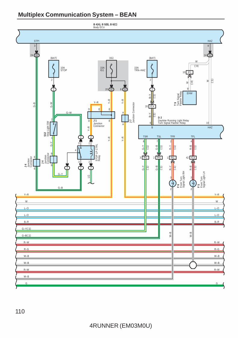
Multiplex Communication System – BEAN
J 4
W
J 1
G–Y
Turn Signal Flasher Relay
LG
Y–R
Y–R
B 4(A), B 5(B), B 6(C)
Y–R
B–Y
Y–R
Y–R
G–B
S12
G–W
HAZ
R–W
W–B
W–B
R–G
B–R
L–O
L–O
W
Y–R
R–W
W–B
W–B
R–G
B–R
L–O
L–O
W
Y–R
G–Y
G–W
Y–R
A
A
83
STPI HAZ
B
EED
10
B
22
D E
8 1J 2
15ATRN–HAZ
2
2
10ASTOP
1
1J
2
3 2
4
5 1
2 2
2
141E24
2
STO
P L
P C
TRL
Rel
ay
20 1E
15AIG1
TFR
R–Y ( ∗1)
2 4
( ∗1)
W–B
R–W R–W
( ∗1)
EHW
8
( ∗4)
J 7
IF110
8
W ( ∗1)
T 9
Body ECU
Turn
Sig
nal
Flas
her
Rel
ay
Junc
tion
Con
nect
or
Junc
tion
Con
nect
or
JunctionConnector
Sto
p Li
ght S
W
F 5
Fron
t Tur
nS
igna
l Lig
ht L
H
W–B
2 IH1
F 6
W–B
G–Y(∗1)
3 IH1
TSR
G–Y
( ∗1)
TSL
G–B
( ∗1)
W
(∗4)
7
Fron
t Tur
nS
igna
l Lig
ht R
H
G
G–B(∗1)
IN11 IC442
2
3
2
3
IC420
6
B
B–Y ( ∗1)
R–B
TFL
D 2
( ∗1)
R–Y
G–Y
( ∗1)
G–B
( ∗1)
( ∗1)
R–BE
Daytime Running Light Relay
E
J 4
Junc
tion
Con
nect
or
G–B
(BAT)(IG)(BAT)
G
4RUNNER (EM03M0U)
111
A
G–R G
W–B
W–B
W–B
GND
GR–G
DINDDEFSW
IG
4 11
7
R
1
3FB
1
B 3F 3C
B
A
5 B
IK
3FB
B
RR
3CA
Y–R
2
IG+
Y–R
G–B
LG–R
G–B
Y–R
G–B
G–B
Y–R
W–B
Y–R
W–B
B 4(A), B 5(B), B 6(C)
J25
IG E
G–B
R–W
W–B
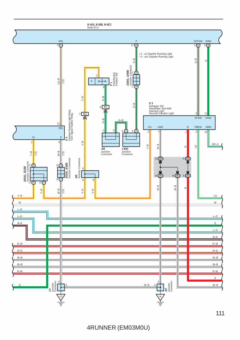
D 2
W–B
R–G
B–R
L–O
DRL
L–O
W
R–W
W–B
W–B
R–G
B–R
L–O
L–O
J22(
A), J
23( B
)
W
Y–R
J35
J18(
A), J
19( B
)
J 8(A)
DRL P
12
A
A
91
17 B
C A
C B
E AE A
8 IM1
2 IM1
F B
H AAH
BD
AE
J20(
A), J
21( B
)
7 A
C
Y–R
A
SIND
A
J37
A
DFSW
J 5
DIND
W–B
12
W–B
R–W R–W
( ∗1)
D 3
LG
PBEW
3
( ∗1)
( ∗1)
( ∗1)
A
Defogger SWPassenger Seat BeltWarning LightSecurity Indicator Light
Body ECU
Day
time
Run
ning
Lig
ht R
elay
Turn
Sig
nal F
lash
er R
elay
Junc
tion
Con
nect
or
Junc
tion
Con
nect
or
Junc
tion
Con
nect
or
Junc
tion
Con
nect
or
JunctionConnector
Junc
tion
Con
nect
or
JunctionConnector
Junc
tion
Con
nect
or
C
2
6
∗ 1 : w/ Daytime Running Light∗ 4 : w/o Daytime Running Light
LG
Y–R
Par
k/N
eutra
lP
ositi
on S
W
P 1
G
G
P
112
4RUNNER (EM03M0U)
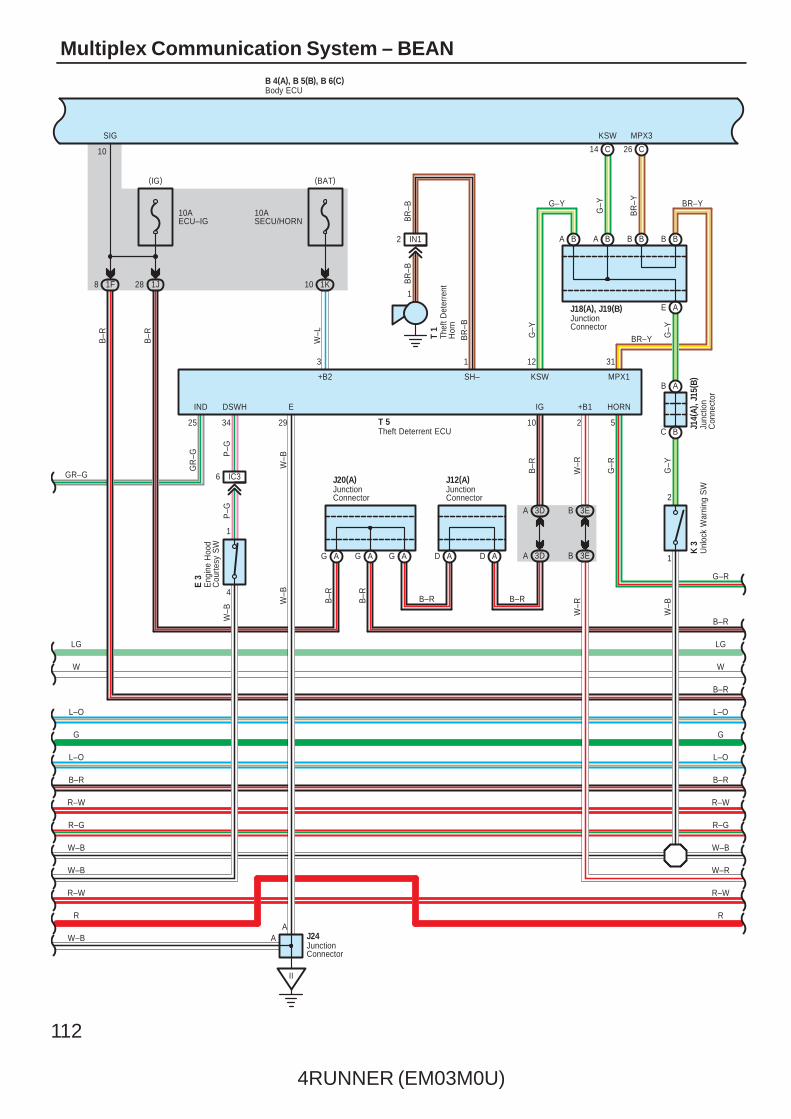
Multiplex Communication System – BEAN
10ASECU/HORN
1K10
1
4
6 IC3
B 4(A), B 5(B), B 6(C)
26C14
II
AG AG AG AD AD
3DA
3DA 3EB
3EB
10AECU–IG
1J281F8
C
AE
G–Y
BBBA
1
2
J14(
A), J
15( B
)
BA
G–Y
10
34 29 10 2
AA
R
3 12 31
B–R
B–R
W
L–O
L–O
B–R
R–W
W–B
W–R
T 5
R–W
W–B
R–W
W–B
W–B
R–W
B–R
L–O
J20(A)
L–O
W
GR–G J12(A)
K 3
J18(A), J19(B)
BR
–B
T 1
BR
–B
BR
–B
SH–
1
2 IN1
1
+B1IGIND EDSWH
MPX3KSWSIG
25
B–R B–R
W–B
G–Y
J24
E 3
G–Y
BR
–Y
W–R
B–R
B–R
B–R
+B2
P–G
W–B
P–G
KSW
W–B
GR
–G
W–L
MPX1
B–R
B–R
W–B
W–R
R–GR–G
LG LG
C B
B A
R
G–R
G–R
Body ECU
Eng
ine
Hoo
dC
ourte
sy S
W
JunctionConnector
JunctionConnector
Junc
tion
Con
nect
or
JunctionConnector
JunctionConnector
Unl
ock
War
ning
SW
Theft Deterrent ECUTh
eft D
eter
rent
Hor
n
BB
BR–Y
BR–YG–Y
5
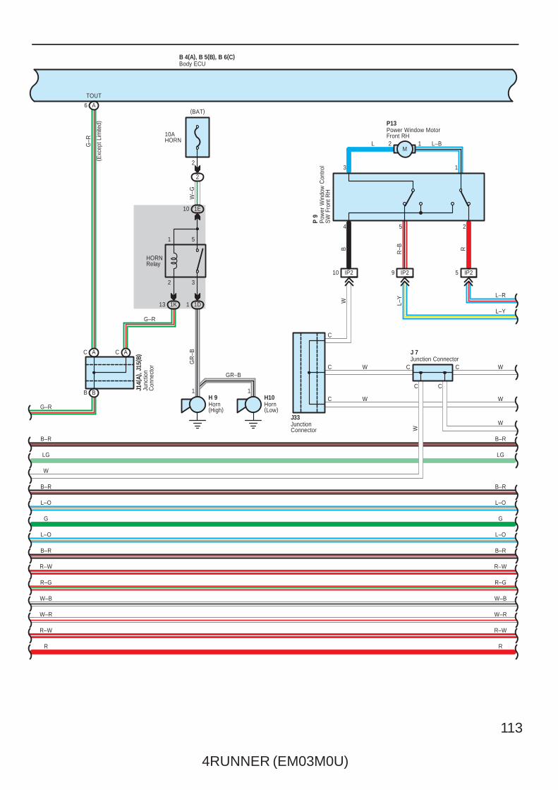
HORN
(BAT)(IG)
G G
4RUNNER (EM03M0U)
113
9 IP2
B 4(A), B 5(B), B 6(C)
10 IP2
12G–R
IP25
TOUT( E
xcep
t Lim
ited)
4 5 2
CC
W
13
C
P13
J 7
B–R
B–R
W
L–O
L–O
B–R
R–W
W–B
W–R
R–W
B–R
B–R
W
L–O
L–O
B–R
R–W
W–B
W–R
R–W
W
W
L–Y
L–R
L L–B
B
R–B R
L–Y
W
W
R–G R–G
LG
CC
C
C W
J33
LG
C A AC
A
H 9
6
W–G
J14(
A), J
15( B
)
HORNRelay
GR
–B
Junc
tion
Con
nect
or
GR–B
2
H10
10AHORN
2
1K13 1 1D
10 1E
1 1B B
51
32
G–R
R
G–R
R
Body ECU
Horn(High)
Horn(Low)
Junction Connector
JunctionConnector
Power Window MotorFront RH
Pow
er W
indo
w C
ontro
lS
W F
ront
RH
P 9
(BAT)
G G
M
114
4RUNNER (EM03M0U)
Multiplex Communication System – BEAN
AAAA AB AB
C22
BCBB
C24
IA27 IA212
IA211 IA210
2
1
IA25
BB15
IA112 IA22
4
13 6 11 718 16
3125
15
L–R
L–Y
W
W
B–R
B–R
W
L–O
L–O
B–R
R–W
W–B
W–R
R R
W–R
W–B
R–W
B–R
L–O
W
B–R
PD PU B B2 BWRRU RRD
LL–BGG
–BG
–B G
B R–L
P15
W
RBB
R–BR
L–O
B–RW
L–Y
L–R
L–Y
L–R
P11
L–Y
L–R
R–B R
W
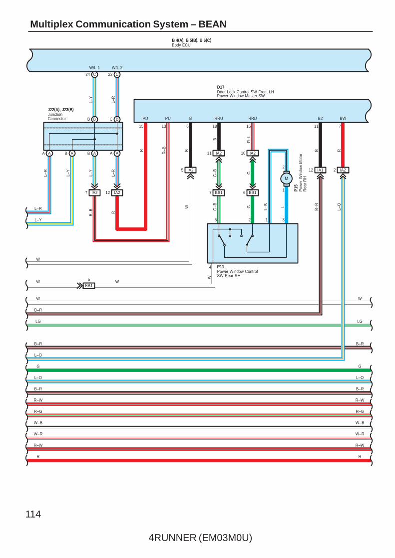
J22(A), J23(B)
D17
W/L 1 W/L 2
R–G R–G
LG LG
BB17 BB16
R–W R–W
Door Lock Control SW Front LHPower Window Master SW
JunctionConnector
Power Window ControlSW Rear RH
Pow
er W
indo
w M
otor
Rea
r R
H
G G
B 4(A), B 5(B), B 6(C)Body ECU
M
4RUNNER (EM03M0U)
115
67 BA1
B 4(A), B 5(B), B 6(C)
BA1
IA29 IA262
1
5 BA1
IA14IA15
IA24
IG
4
12 10 9 4 173 14 2 1 8 5
B
654 321
3125
B
B B
R–W
W–R
W–B
R–W
B–R
L–O
B–R
W–B
W–B
L–O
L–W
B–R
W
L–O
B–R
R–W
W–B
W–R
R
RLU RLD DD DU PLS2VCC PLS GND E UL L
R–W
G–W
W–B
BR
–B
W–R
W–L
W–GLL–B
LL–B
G–R
G–W
G–W
G–R
L G
P14
W
W–B
W–B
AJ 5
P12
J38
P10
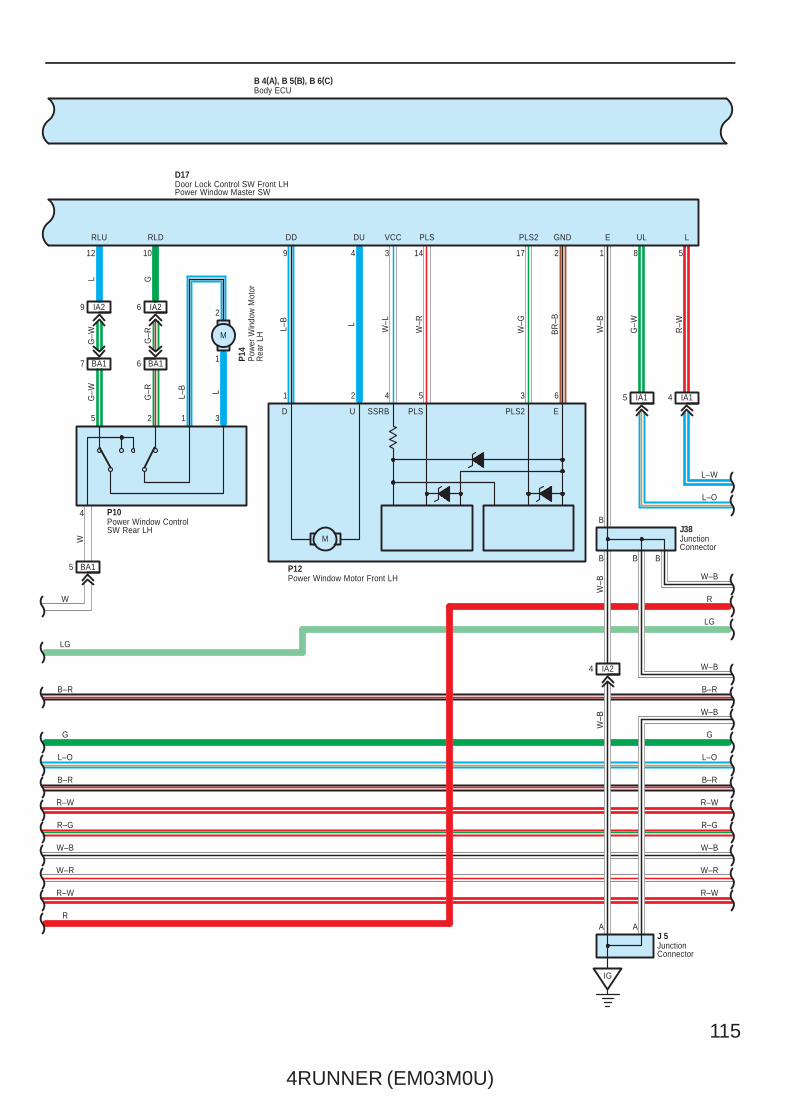
D17
A
W–B
R–GR–G
LG
LG
R–W
R
Body ECU
Door Lock Control SW Front LHPower Window Master SW
JunctionConnector
JunctionConnector
Power Window ControlSW Rear LH
Power Window Motor Front LH
Pow
er W
indo
w M
otor
Rea
r LH
M
SSRB PLS PLS2 EUD
G G
M

116
4RUNNER (EM03M0U)
Multiplex Communication System – BEAN
W–R
W
LSWD
8
21 A
7 IA1
B 4(A), B 5(B), B 6(C)
IK
4 IP2
5 IP1IP16
1K15 1K
IA16 IA18 IA213 IA28
1K3
A12 A10 A30201519
A D A D 5 6 3
7
41109
DA
L–W
L–O
W–B
W–B
B–R
W–B
L–O
B–R
R–W
W–B
W–R
R–W
A
B–W
L–R
W–B
W–B
B–R
W–B
W–B
L–O
B–R
R–W
W–B
W–R
R–W
LSWPACTDUL3
D16
L2UL1L1
W–B
B–WB–RGL
W–B
W–B
W–B
W–B
D18
L G L–B
L–W
L–O
R L
L–O
L–W
L–O
L–W
J 6
L–O
L–W
R–G R–G
LG LG
Unl
ock
Lock
RR
Body ECU
Door Key Lock and Unlock SW Front LHDoor Lock Detection SW Front LHDoor Lock Motor Front LH
Door Lock Control SWFront RH
JunctionConnector
JunctionConnector
J37
A
G G
M
4RUNNER (EM03M0U)
117
98
B 4(A), B 5(B), B 6(C)
IP17 IP27 IP22
6 1L1L181L9
BA110 BA111 BA112
11 1L1L23
BB110 BB111 BB112
10 1L1L221K151L16
BB14BA14
B20
IC512
6 1 4 6 1 44
52423
9
417
B–W
L–R
W–B
W–B
B–R
W–B
W–B
L–O
B–R
R–W
W–B
W–R
R–W
W–B
W–B
B–R
L–O
B–R
R–W
W–B
W–R
R–W
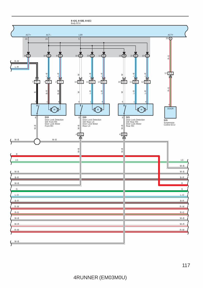
ACTY
S15
ACT+ ACT– LSR
R–G
R–G
L–R
L–B
WL–R
L–B
WL–R
L–B
L–R
L–B
WL–R
L–B
WB–WB–RB
W–B
W–B
W–B
W–B
W–B
DOOR
R–G R–G
D19 D20 D21
LG LG
R
R
SuspensionControl ECU
Body ECU
Door Lock DetectionSW Front RHDoor Lock MotorFront RH
Door Lock DetectionSW Rear LHDoor Lock MotorRear LH
Door Lock DetectionSW Rear RHDoor Lock MotorRear RH
W–B
G G
MMM

118
4RUNNER (EM03M0U)
Multiplex Communication System – BEAN
R
W–B
B 4(A), B 5(B), B 6(C)
1B10 1B6
IE138 IE139 IE141
B4 B3
BA
AAAAAA
BO
10ADOME
2
DOMERelay
3 1
5 2
2 2
2 2
A3
IC31IC410
R–W
W–R
W–B
R–G
R–W
B–R
L–O
B–R
W–B
W–B
R
W–B
W–B
B–R
W–B
L–O
B–R
R–W
R–G
W–B
W–R
7. 5AGAUGE
1G4
9 7
2
D D D
532
1
2
R
R
RR R
RL–R
G–O R R
L–R
G–O R
J40(
A), J
41( B
)
P–B
W–B
Y–B
W–B
W–B
W–B
R
W–B
R–W
W 3
E
D 7
LMRYPRGRDABZR2BZR
1
J 7
RDA PRG +B
LG
R
LG
Body ECU
Door ControlReceiver
Junction Connector
Junc
tion
Con
nect
or
Wire
less
Doo
rLo
ck B
uzze
r
R–L
(IG)
(BAT)
G G
4RUNNER (EM03M0U)
119
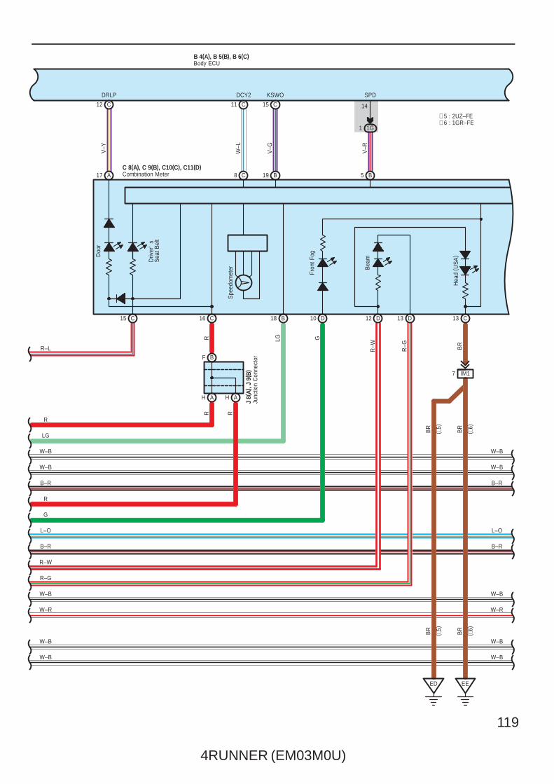
B
W–BW–B
B 4(A), B 5(B), B 6(C)
Driv
er'
sS
eat B
elt
C12 C11 C15
1G1
C15 C16
519 BC8A17
BF
AH
R
W–B
W–B
B–R
W–B
L–O
B–R
R–W
R–G
W–B
W–R
14
SPD
LG
18
R–L
V–R
V–G
W–L
V–Y
RR
J 8(
A), J
9( B
)
W–B
W–B
B–R
W–B
L–O
B–R
W–B
W–R
KSWODCY2DRLP
B
LG
Combination MeterC 8(A), C 9(B), C10(C), C11(D)
Spe
edom
eter
R
AH
R
Body ECU
Junc
tion
Con
nect
or
Doo
r
D12 D13 C13
EE
IM17R
–W R–G BR
BR
BR
Bea
m
Hea
d ( U
SA
)
ED
BR
( ∗6)
( ∗6)
BR
( ∗5)
( ∗5)
G
G10 D
Fron
t Fog
∗ 6 : 1GR–FE∗ 5 : 2UZ–FE
120
4RUNNER (EM03M0U)
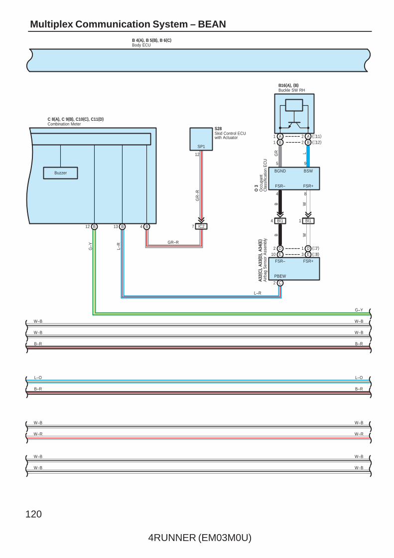
Multiplex Communication System – BEAN
B13
Buzzer
12
B12
G–Y
S28
SP1
Skid Control ECUwith Actuator
Combination MeterC 8(A), C 9(B), C10(C), C11(D)
B–R
B 4(A), B 5(B), B 6(C)Body ECU
B4
W–B
W–R
W–B
W–B
L–O
B–R
W–B
W–B
IC27
GR
–R
D1 (∗7)E3 (∗8)
2 DE10
C2
BI14 BI11
G–Y
W–B
W–B
B–R
L–O
B–R
W–B
W–R
W–B
W–B
A32(
C) ,
A33(
D) ,
A34(
E)A
irbag
Sen
sor
Ass
embl
y
O 3
Occ
upan
tC
lass
ifica
tion
EC
U
4
B16(A), (B)Buckle SW RH
8
5
FSR+
FSR+FSR–
9
GR
PBEW
L
BGND
B W
B W
FSR–
L–R
BSW
A1B1
A2 (∗11)B2 (∗12)
L–R GR–R
4RUNNER (EM03M0U)
121
∗ 6 : 1GR–FE∗ 7 : w/ Side Airbag
∗ 5 : 2UZ–FE
∗ 8 : w/o Side Airbag
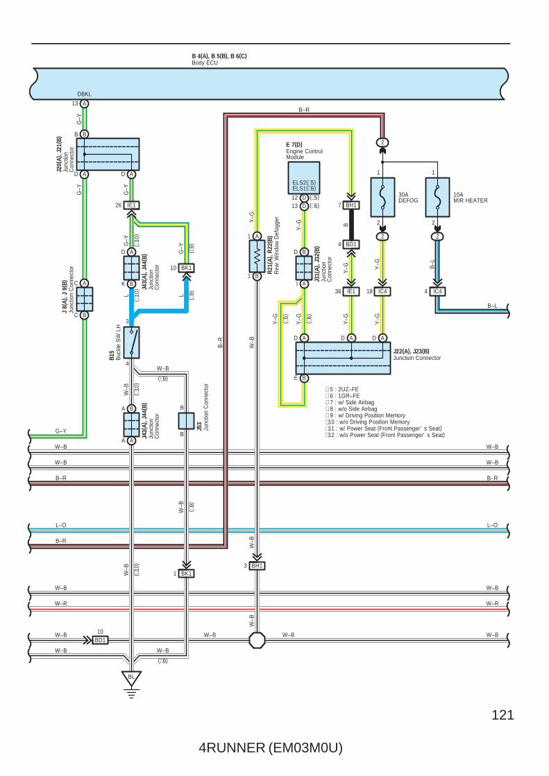
Y–G
Y–G
E 7(D)
Y–G ( ∗5)
Junc
tion
Con
nect
or
Engine ControlModule
W–B
ELS2(∗5)ELS1(∗6)
J31(
A), J
32( B
)
I A
D B
W–B
L
B 4(A), B 5(B), B 6(C)
AD AD
A13
BB
IE126
2
30ADEFOG
10AMIR HEATER
D
2 2
IC418 IC44
ADADA
( ∗6)
IE136
BD14
BH17
A1
B1
BE
BD110
BH13
R21
( A) ,
R22
( B)
B15
1
J 8(
A), J
9( B
)
1
2 2
B–L
DBKL
G–Y
W–B
W–B
B–R
L–O
B–R
W–B
W–R
W–B
W–B
W–B
B–R
L–O
W–B
W–R
W–B
W–B
W–B
Y–G
Y–G
Y–G B–L
Y–G
B
Y–G
G–Y
G–Y
G–Y
B–R
W–B
W–B W–B
J43(
A), J
44( B
)Ju
nctio
nC
onne
ctor
Body ECU
Buc
kle
SW
LH
Junc
tion
Con
nect
or Rea
r W
indo
w D
efog
ger
B
AC
A
AA
BC
J43(
A), J
44( B
)
3
J20(
A), J
21( B
)Ju
nctio
nC
onne
ctor
K B
D
BL
W–B
A
Junc
tion
Con
nect
or
G–Y
4
B–R
∗ 9 : w/ Driving Position Memory∗10 : w/o Driving Position Memory∗11 : w/ Power Seat (Front Passenger' s Seat)∗12 : w/o Power Seat (Front Passenger' s Seat)
Junction ConnectorJ22(A), J23(B)
( ∗10
)
BK110
( ∗10
)( ∗
10)
( ∗10
)
G–Y
( ∗9)
L ( ∗9)
B
B
BK11
W–B
( ∗9)
W–B
(∗9)
W–B
(∗9)
Junc
tion
Con
nect
orJ5
3(∗5)D12(∗6)D13
122
4RUNNER (EM03M0U)
Multiplex Communication System – BEAN
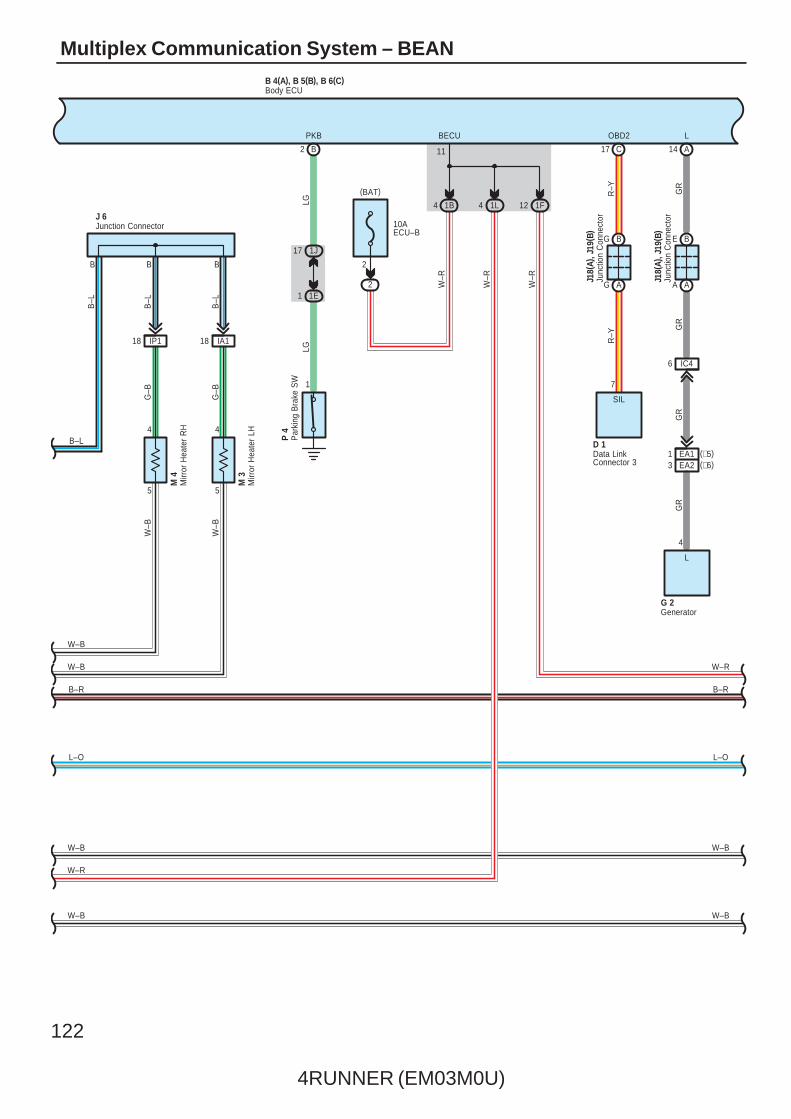
12 1F
11
4 1L1B4
BECU
2
B 4(A), B 5(B), B 6(C)
IA11818 IP1
5
4
5
4
10AECU–B
B2
1
1J17
1E1
B B B
W–R
W–R
PKB
B–L
W–B
W–B
B–R
L–O
W–B
W–R
W–B W–B
W–R
L–O
B–R
2
LG
W–R
LG
B–L
B–L
B–L
G–B
G–B
W–B
W–B
M 4
M 3
J 6
P 4
W–B
Body ECU
Junction Connector
Par
king
Bra
ke S
W
Mirr
or H
eate
r LH
Mirr
or H
eate
r R
H
C17
BG
AG
BE
AA
IC46
A14
7
4
LOBD2
R–Y GR
R–Y
GR
GR
GR
G 2
D 1
L
SIL
J18(
A), J
19( B
)
J18(
A), J
19( B
)
3 EA21 EA1 (∗5)
(∗6)Data LinkConnector 3
Generator
Junc
tion
Con
nect
or
Junc
tion
Con
nect
or
(BAT)
4RUNNER (EM03M0U)
123
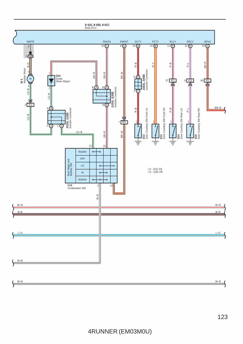
IO36
B 4(A), B 5(B), B 6(C)
A23
40 IE1
MPX2
BR–R
BR
–R
13
12 10
2
2
WMTR RWON RWINT
BR
–W
GR
–R
B–O
LG–B
GR
–R
BR
–W
W–B
Washer
OFF
LO
HI
Washer
W 2
1B1
4
3
IC33
7 IH1
C10 C9
W–R
B–R
L–O
W–B
Body ECU
Rea
r W
iper
and
Was
her
SW
Was
her
Mot
or
Combination SWC14
Junc
tion
Con
nect
or
Doo
r C
ourte
sy S
W R
ear
RH
Doo
r C
ourte
sy S
W R
ear
LH
Doo
r C
ourte
sy S
W F
ront
RH
Doo
r C
ourte
sy S
W F
ront
LH
D13
D12
DCTY PCTY RLCY RRCY
J18(
A), J
19( B
)
D14
D15
R–Y
P–L
P–B
R–B
R–B
P–B P–L
12 BB1124 B23 B
1 111
37 IE1
F A
H B
∗ 6 : 1GR–FE∗ 5 : 2UZ–FE
W–R
B–R
L–O
W–B W–B
BB
ABAB
AC AC
BA
2
1
GR
–R
LG–B
LG–B
LG–B
Junc
tion
Con
nect
orJ1
2(A)
, J13
( B)
Junc
tion
Con
nect
orJ1
2(A)
, J13
( B)
Diode(Rear Wiper)
D24M

124
4RUNNER (EM03M0U)
Multiplex Communication System – BEAN
BD19
A1 A5 6 A A4 A3
BD17 5 BD1 BD16
B10 B22 B19 B4 B5
123
UPDOWNEHSW–HSW+GNDBDRSIGBECUMPX2
V–Y
GR
–R
LG–B
LG–R
V–W
W–BL
L–RR B
2
W–B
W–R
B–R
L–O
B 8(A), B 9(B)
T10
1B1
0
Back Door ECU
Bac
k D
oor
Ope
ner
SW
Tailgate Control SW
BR–R
L–O
B–R
W–R
Back Door Lock MotorBack Door Lock Detection SWBack Door Half Latch SWBack Door Courtesy SW
M
B 7
R–G
G–Y
BR
–W
L–B
L–R
HALF FULL POS ACT+ ACT–
5 6 4 1 2
B21
3
14 B15 B8 B7 B6 B
LSE
B–R
F
F
E
E
Junc
tion
Con
nect
or
J39
4RUNNER (EM03M0U)
125
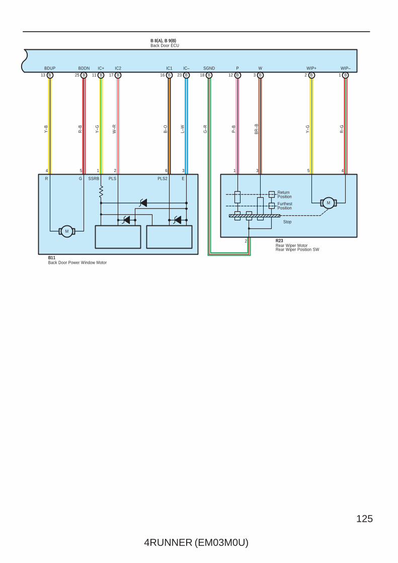
B25B13 B11 B16B17 B23
IC–IC2 IC1IC+BDUP BDDN
L–W
W–R
B–O
Y–GY–B
R–B
B 8(A), B 9(B)
B11
Back Door ECU
Back Door Power Window Motor
321 654
M
SSRB PLS PLS2 EGR
1 B2 B18 B 12 B 3 B
Y–G
WIP+
1
SGND P
G–R
P–B
WIP–
BR
–B
W
453
R–G
Stop
ReturnPosition
FurthestPosition
M
2 R23Rear Wiper MotorRear Wiper Position SW

126
4RUNNER (EM03M0U)
Multiplex Communication System – BEAN
Communication OutlineCommunication is made among the body, theft deterrent and back door ECUs.When the ECU receives a signal from related switches, i.e., the rear wiper SW, the body ECU sends signals to the back doorECU, and moves rear wiper.For details, please refer to the new car features and/or the repair manual.
System Outline

4RUNNER (EM03M0U)
127
: Parts Location
Code See Page Code See Page Code See Page
A32 C 36 F2 34 (1GR–FE) J37 38
A33 D 36F5
32 (2UZ–FE) J38 40
A34 E 36F5
34 (1GR–FE) J39 40
A39 36F6
32 (2UZ–FE) J40 A 40
B1 36F6
34 (1GR–FE) J41 B 40
B4 A 36G2
32 (2UZ–FE)J43 A
42 (*1)
B5 B 36G2
34 (1GR–FE)J43 A
43 (*2)
B6 C 36H1
32 (2UZ–FE)J44 B
42 (*1)
B7 40H1
34 (1GR–FE)J44 B
43 (*2)
B8 A 40H2
32 (2UZ–FE) J53 42 (*1)
B9 B 40H2
34 (1GR–FE) K3 39
B10 40H3
32 (2UZ–FE) L2 40
B11 40H3
34 (1GR–FE) M3 41
B1542 (*1)
H432 (2UZ–FE) M4 41
B1543 (*2)
H434 (1GR–FE) M5 41
B16
A42 (*1)
H932 (2UZ–FE)
O342 (*1)
B16
A43 (*2)
H934 (1GR–FE)
O343 (*2)
B16
B42 (*1)
H1032 (2UZ–FE)
P133 (2UZ–FE)
B43 (*2)
H1034 (1GR–FE)
P135 (1GR–FE)
C8 A 37 I17 37 P4 39
C9 B 37I20
A 40 P7 41
C10 C 37I20
B 40 P9 41
C11 D 37J1
33 (2UZ–FE) P10 41
C12 37J1
35 (1GR–FE) P11 41
C14 37J3
33 (2UZ–FE) P12 41
D1 37J3
35 (1GR–FE) P13 41
D2 37 J4 38 P14 41
D3 37 J5 38 P15 41
D7 40 J6 38 R21 A 41
D8 40 J7 38 R22 B 41
D9 40 J8 A 38 R23 41
D10 40 J9 B 38 S12 39
D11 40 J10 A 38 S15 39
D12 40 J11 B 38S28
33 (2UZ–FE)
D13 40 J12 A 38S28
35 (1GR–FE)
D14 40 J13 B 38 S32 41
D15 40 J14 A 38 S33 41
D16 40 J15 B 38 S34 41
D17 40 J18 A 38 S35 41
D18 40 J19 B 38T1
33 (2UZ–FE)
D19 40 J20 A 38T1
35 (1GR–FE)
D20 40 J21 B 38 T5 39
D21 40 J22 A 38 T9 39
D24 37 J23 B 38 T10 41
E332 (2UZ–FE) J24 38 V6 41
E334 (1GR–FE) J25 38 V7 41
E7 D 37 J31 A 38W2
33 (2UZ–FE)
F132 (2UZ–FE) J32 B 38
W235 (1GR–FE)
F134 (1GR–FE) J33 38
W333 (2UZ–FE)
F2 32 (2UZ–FE) J35 38W3
35 (1GR–FE)
* 1 : Power Seat * 2 : Manual Seat
128
4RUNNER (EM03M0U)
Multiplex Communication System – BEAN
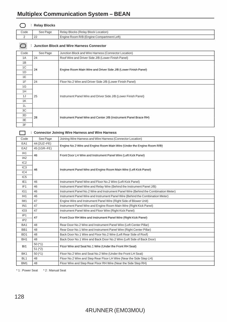
: Relay Blocks
Code See Page Relay Blocks (Relay Block Location)
2 22 Engine Room R/B (Engine Compartment Left)
: Junction Block and Wire Harness Connector
Code See Page Junction Block and Wire Harness (Connector Location)
1A 24 Roof Wire and Driver Side J/B (Lower Finish Panel)
1B
24 Engine Room Main Wire and Driver Side J/B (Lower Finish Panel)1C
24 Engine Room Main Wire and Driver Side J/B (Lower Finish Panel)1D
24 Engine Room Main Wire and Driver Side J/B (Lower Finish Panel)
1E
1F 24 Floor No.2 Wire and Driver Side J/B (Lower Finish Panel)
1G
25 Instrument Panel Wire and Driver Side J/B (Lower Finish Panel)
1H
25 Instrument Panel Wire and Driver Side J/B (Lower Finish Panel)1J 25 Instrument Panel Wire and Driver Side J/B (Lower Finish Panel)
1K
25 Instrument Panel Wire and Driver Side J/B (Lower Finish Panel)
1L
3C
28 Instrument Panel Wire and Center J/B (Instrument Panel Brace RH)3D
28 Instrument Panel Wire and Center J/B (Instrument Panel Brace RH)3E
28 Instrument Panel Wire and Center J/B (Instrument Panel Brace RH)
3F
: Connector Joining Wire Harness and Wire Harness
Code See Page Joining Wire Harness and Wire Harness (Connector Location)
EA1 44 (2UZ–FE)Engine No.2 Wire and Engine Room Main Wire (Under the Engine Room R/B)
EA2 45 (1GR–FE)Engine No.2 Wire and Engine Room Main Wire (Under the Engine Room R/B)
IA146 Front Door LH Wire and Instrument Panel Wire (Left Kick Panel)
IA246 Front Door LH Wire and Instrument Panel Wire (Left Kick Panel)
IC2
46 Instrument Panel Wire and Engine Room Main Wire (Left Kick Panel)IC3
46 Instrument Panel Wire and Engine Room Main Wire (Left Kick Panel)IC4
46 Instrument Panel Wire and Engine Room Main Wire (Left Kick Panel)
IC5
IE1 46 Instrument Panel Wire and Floor No.2 Wire (Left Kick Panel)
IF1 46 Instrument Panel Wire and Relay Wire (Behind the Instrument Panel J/B)
IG1 46 Instrument Panel No.2 Wire and Instrument Panel Wire (Behind the Combination Meter)
IH1 46 Instrument Panel Wire and Instrument Panel Wire (Behind the Combination Meter)
IM1 47 Engine Wire and Instrument Panel Wire (Right Side of Blower Unit)
IN1 47 Instrument Panel Wire and Engine Room Main Wire (Right Kick Panel)
IO3 47 Instrument Panel Wire and Floor Wire (Right Kick Panel)
IP147 Front Door RH Wire and Instrument Panel Wire (Right Kick Panel)
IP247 Front Door RH Wire and Instrument Panel Wire (Right Kick Panel)
BA1 48 Rear Door No.2 Wire and Instrument Panel Wire (Left Center Pillar)
BB1 48 Rear Door No.1 Wire and Instrument Panel Wire (Right Center Pillar)
BD1 48 Back Door No.1 Wire and Floor No.2 Wire (Left Rear Side of Roof)
BH1 48 Back Door No.1 Wire and Back Door No.2 Wire (Left Side of Back Door)
BI150 (*1)
Floor Wire and Seat No.1 Wire (Under the Front RH Seat)BI151 (*2)
Floor Wire and Seat No.1 Wire (Under the Front RH Seat)
BK1 50 (*1) Floor No.2 Wire and Seat No.2 Wire (Under the Front LH Seat)
BL1 48 Floor No.2 Wire and Step Rear Floor LH Wire (Near the Side Step LH)
BM1 48 Floor Wire and Step Rear Floor RH Wire (Near the Side Step RH)
* 1 : Power Seat * 2 : Manual Seat
4RUNNER (EM03M0U)
129
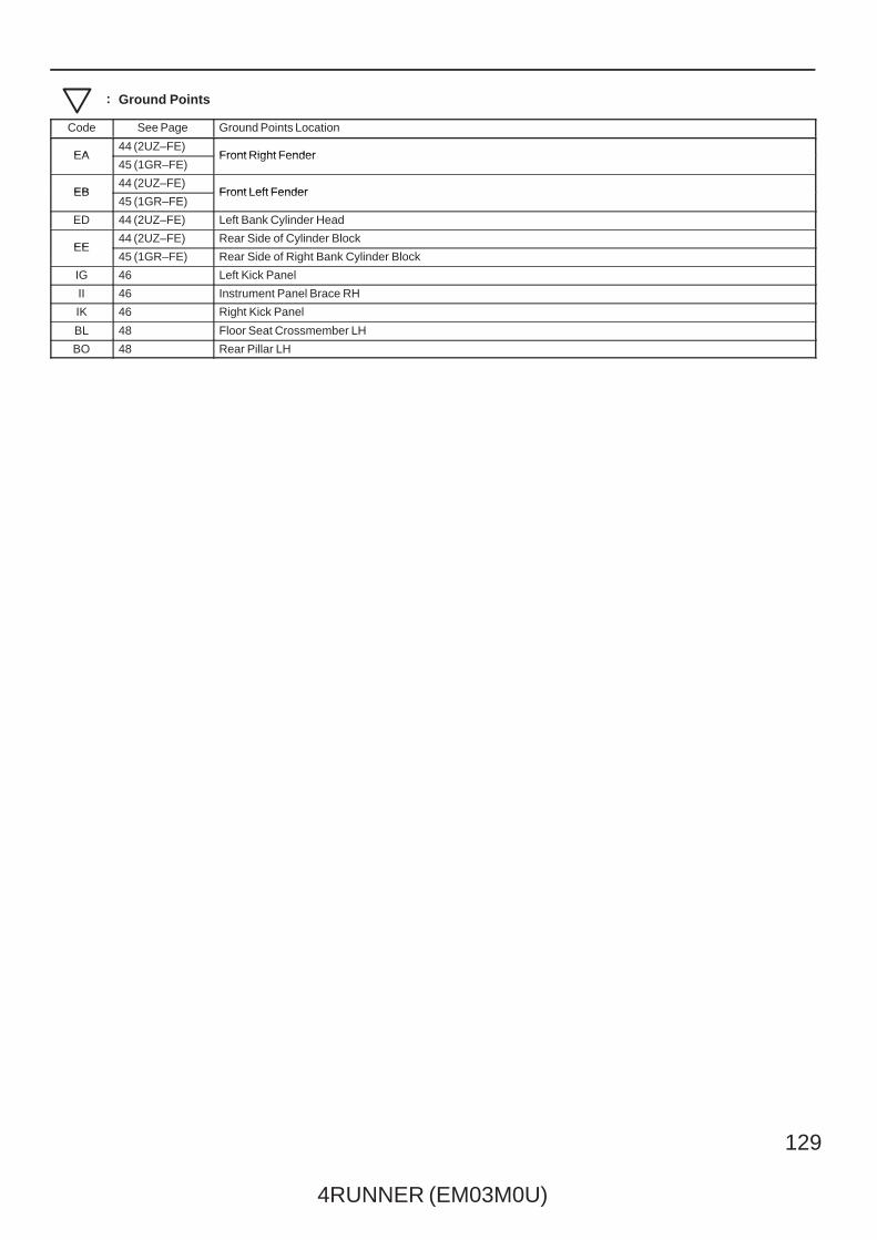
: Ground Points
Code See Page Ground Points Location
EA44 (2UZ–FE)
Front Right FenderEA45 (1GR–FE)
Front Right Fender
EB44 (2UZ–FE)
Front Left FenderEB45 (1GR–FE)
Front Left Fender
ED 44 (2UZ–FE) Left Bank Cylinder Head
EE44 (2UZ–FE) Rear Side of Cylinder Block
EE45 (1GR–FE) Rear Side of Right Bank Cylinder Block
IG 46 Left Kick Panel
II 46 Instrument Panel Brace RH
IK 46 Right Kick Panel
BL 48 Floor Seat Crossmember LH
BO 48 Rear Pillar LH