Embed Size (px)
Citation preview

Instructions for use
Title Multidisciplinary Design Optimization for Vibration Control of Smart Laminated Composite Structures
Author(s) Honda, Shinya; Kajiwara, Itsuro; Narita, Yoshihiro
Citation Journal of Intelligent Material Systems and Structures, 22(13): 1419-1430
Issue Date 2011-09
Doc URL http://hdl.handle.net/2115/49929
RightsThe final, definitive version of this article has been published in the Journal, Journal of Intelligent Material Systems andStructures, 22(13), 2011 of publication, © SAGE Publications Ltd, 2011 by SAGE Publications Ltd at the Journal ofIntelligent Material Systems and Structures page: http://jim.sagepub.com/ on SAGE Journals Online:http://online.sagepub.com/
Type article (author version)
File Information JIMSS22-13_1419-1430.pdf
Hokkaido University Collection of Scholarly and Academic Papers : HUSCAP

0
Multidisciplinary Design Optimization for Vibration Control of Smart
Laminated Composite Structures
Shinya HONDA, Itsuro KAJIWARA, and Yoshihiro NAIRTA
Faculty of Engineering, Hokkaido University
N13W8, Kita-ku, Sapporo, 060-8628, Hokkaido, Japan
ABSTRACT
The structure and vibration control system of smart laminated composites consisting of graphite-epoxy
composites and piezoelectric actuators are designed for optimum vibration suppression. The placement of
piezoelectric actuators, the lay-up configurations of laminated composite plates and the H2 control system
are employed as design variables and they are optimized simultaneously by a simple genetic algorithm
(SGA). To reduce complexity, only pre-selected families of lay-up configurations are considered. An
objective function is the H2 performance with respect to the controlled response for vibration suppression. A
multidisciplinary design optimization is performed with the above three design variables and then the output
feedback system is reconstructed with a dynamic compensator based on a linear matrix inequality (LMI)
approach. The validity of the modeling and calculation technique is confirmed experimentally. Optimization
results show that optimized smart composites with the present approach successfully realize vibration
suppression and it is confirmed that the proposed multidisciplinary design optimization technique enhances
the vibration suppression of smart composites.
Key Words: vibration control, laminated composite, robust control, piezoelectric, modal transformation,
optimization, genetic algorithm
1
INTRODUCTION
Advantages of advanced composite materials in industrial use are becoming increasingly obvious. Among
types of composites, laminated fibrous composites are finding a wide range of applications in structural design,
especially for light-weight structures that have strict stiffness and strength requirements. In many applications,
light-weight structures are typically exposed to severe vibration environments, and vibration suppression of
composites is becoming increasingly important. A smart composite with a piezoelectric (PZT) actuator and sensor
is an effective solution to suppress structural vibration, and in this study, structures and control systems of smart
laminated composites are designed for optimum vibration suppression.
The performance of vibration control of structures strongly depends on the location of actuators as the
optimum placement of actuators results in activating control forces effectively in the structures. Many studies on
this problem have been reported: Quek, Wang and Ang (2003) proposed an optimization technique for the
placement of PZT actuators and sensors to suppress the vibration of composite plates using a pattern search
method. Jha and Inman (2003) determined optimum placements and sizes of actuators and sensors using a genetic
algorithm (GA) method for inflated torus structures. Ono, Kajiwara and Ishizuka (2007) developed a
simultaneous optimization method for actuator placements and H2 control systems to suppress plate vibration with
a finite element analysis (FEA) and sound pressure levels with a boundary element method (BEM). Rader et al.
(2007) presented an approach to optimizing the placement of piezoelectric actuators considering different
numbers of actuators for the vibration control of a flexible aircraft fin. Rao et al. (2008) employed a particle
swarm based evolutionary optimization technique for optimization of actuator placement to improve H∞ control
performance. Kang and Tong (2008) optimized the topologies of PZT actuators and control voltage
simultaneously by a method of moving asymptotes. Kajiwara, Takahashi and Arisaka (2009) applied an actuator
placement technique to the arm of hard disk drives to enhance the servo bandwidth of the head positioning
system. However, the above studies limited the controlled objects to isotropic structures or anisotropic composites
with pre-established lay-up configurations.

2
Laminated composites can be tailored by varying the stacking sequences of the fiber orientation angles in
each layer and/or layer thickness. Generally, laminated composites are created by stacking orthotropic layers
termed lamina with different fiber orientation angles. The mechanical properties of laminated composites depend
on the lay-up configurations and it is possible to design vibration characteristics of the plate arbitrarily by
arranging fiber orientation angles. The use of lamination parameters (Gürdal, Haftka and Hajela, 1999) which
describe equivalent stiffnesses for the through-thickness of plates in a simple form is an effective approach
towards an optimization of lay-up configurations, but it requires a two-step optimization process to obtain the
practical lay-up configurations or fiber orientation angles in each layer, and deriving a lay-up configuration
corresponding to the parameters is not straightforward. Fukunaga, Sekine and Sato (1992) proposed an
optimization method to maximize the fundamental frequency using lamination parameters. They first determined
optimum parameters with a mathematical programming method and then the corresponding lay-up configuration
for the parameters were derived by a graphical method. Autio (2000) used a GA to determine the lay-up
corresponding to the lamination parameters. Honda, Narita and Sasaki (2009) presented an effective method for
converting lamination parameters to lay-up configurations by dividing a laminate into sub-domains. Matsuzaki
and Todoroki (2007) proposed an optimization technique using a fractal branch-and-bound method for the
lamination parameters. Meanwhile, optimization techniques of laminated composites without lamination
parameters have been also proposed to avoid two-step optimization. Riche and Haftka (1993) maximized buckling
loads of laminated composite plates using a GA, directly assigning fiber orientation angles in each layer as a
design variable. Narita (2003) proposed a layerwise optimization (LO) method and determined fiber orientation
angles sequentially from the outermost to the innermost layers. The objectives of these studies have been to
maximize the fundamental frequencies or buckling loads of the laminated composites. However, it is becoming
increasingly difficult to satisfy the strict vibration requirements for laminated composites in recent advanced
mechanical structures by only structural design, and thus smart composites with active vibration control is a
promising approach to improving the vibration properties of mechanical structures.
An optimization method is proposed here to improve the active vibration control performance of smart
laminated composites. In the optimization problem, the fiber orientation angles and their stacking sequences are

3
determined multidisciplinary with PZT actuator placement and control system to enhance vibration suppression of
the smart structures. As mentioned above, many studies have reported optimization of lay-up configurations and
actuator placements separately for smart composites, but no study has optimized both the lay-up configurations
and the actuator placements simultaneously. In the approach here, the smart composite is modeled by finite
elements and the order of the model is reduced by modal coordinate transformation. The vibration control system
is designed by solving the H2 control problem using a reduced-order modal model. The multidisciplinary design
optimization is performed with respect to the smart composite by a simple genetic algorithm method (SGA)
assuming the state feedback and then the output feedback system is reconstructed based on the linear matrix
inequality (LMI) approach. The experimental results prove the validity of the proposed approach on the
multidisciplinary design optimization, and the numerical results show that the obtained composite plates with
optimum lay-ups, actuator placements and control systems provide better suppression of the vibration response
than plates with other lay-up configurations.
ANALSYS AND OPTIMIZATION METHOD
Stiffnesses of Laminated Composites
A symmetric K-layered plate with respect to the middle surface as shown in Figure 1 is considered here. The
plate dimensions are a × b × h (h: thickness), where h is thin enough to satisfy the plane stress condition. The
fiber direction and the direction normal to the fibers in the kth layer are defined as 1 and 2, respectively. The
stress-strain relation in the direction of the material principal axis is given by
1 111 12
2 12 22 2
6612 12
0
0
0 0
Q Q
Q Q
Q
(1)
where Qij (i, j = 1, 2, 6) are stiffness coefficients defined by the material constants in the direction of the material
principal axis.

4
11 1 12 21 22 2 12 21
12 21 11 12 22 66 12
1 , 1
,
/( ) /( ),Q E Q E
Q Q Q Q G
(2)
Here, E1 and E2 are the moduli of elasticity in the fiber and normal to the fiber direction, G12 is the shear modulus,
and ν12 and ν21 are the major and minor Poisson ratios. Rotating the axis systems in Fig. 1 by an amount θk, the
fiber orientation angle in the kth layer defined from the x axis in the counterclockwise direction gives the stress-
strain relation with respect to the O-xy coordinates.
11 12 16
12 22 26
16 26 66
x x
y y
xy xy
Q Q Q
Q Q Q
Q Q Q
(3)
where ijQ (i, j = 1, 2, 6) are the transformed stiffness coefficients. With material invariants Ui (i = 1, 2, … 5), they
are given by
111
22 1
12 42
5663
16
26
cos cos 4
cos cos 41
0 cos 4
0 cos 4
0 (sin 2 ) / 2 sin 4
0 (sin 2 ) / 2 sin 4
k k
k k
k
k
k k
k k
Q UQ U
Q UU
UQU
Q
Q
(4)
and Ui are
111
222
312
466
5
3 /8 3/8 1/ 4 1/ 2
1/ 2 1/ 2 0 0
1/8 1/8 1/ 4 1/ 2
1/8 1/8 3/ 4 1/ 2
1/8 1/8 1/ 4 1/ 2
UQ
UQ
UQ
UQ
U
(5)
The relations between the resultant stress-strain and the resultant moment-curvature are obtained by a through-
thickness integration of Equation (3). The plate is limited to symmetrically laminated plates here and so the in-
plane and out-of-plane coupling is cancelled. Then, the in-plane stiffnesses Aij and the out-of-plane stiffnesses Dij
(i, j = 1, 2, 6) can be considered independently. With zk, which is the z coordinate of the outer surface of the kth
layer, Aij and Dij are expressed by

5
11
3 31
1
( ) ( )
1( ) ( )
3
K
ij ij k k kk
K
ij ij k k kk
A Q z z
D Q z z
(6)
In the finite element analysis, the element stiffness is defined using the stiffnesses in Equation (6) and the
frequencies and modal vectors depend on Aij and Dij.
Modeling of Smart Structures
Finite element analysis (FEA) is used to model smart structures and the order of the finite element model is
reduced with the modal analysis technique. The finite element model of the composite plate here is shown in
Figure 2. The plate right edge is clamped and the dimensions of the plate are a × b × h = 200 × 160 × 2 mm with
10 × 8 = 80 elements. The locations for an accelerometer and an impulse (disturbance) input are also shown in
Figure 2. The lay-up configurations of laminated composites are limited to symmetric eight layers [θ1/θ2/θ3/θ4]s
where θ1 is the angle in the outermost layer. The general purpose FEA software (ANSYS 11.0) is used with the
linear layered structural shell element (SHELL99) for the modeling of the plate, SHELL99 is a quadratic element
and the number of nodes in the model here is 277. Assuming graphite/epoxy (CFRP) composite, the material
constants are: E1 = 141 GPa, E2 = 10.0 GPa, G12 = 7.17 GPa, ν12 = 0.28 and ρ = 1600 kg/m3. Properties of PZT
actuator are listed in Table 1. The actuators have 0.5 mm thickness and 15 mm width but their mass and stiffness
effects are neglected in the modeling since they are thin enough compared with CFRP plate, and they are assumed
as segments of line and input points of control forces at their end points.
The equation of motion for an n degree-of-freedom system is expressed as
1 2s s s s s M x C x K x B w B u (7)
where Ms and Ks are the mass and stiffness matrixes; Cs is the assumed proportional viscous damping matrix; and
x, w and u are the displacement, disturbance and control input vectors, respectively. A finite element model is
flexible and able to accommodate a wide range of shapes, as well as it is an effective modeling method, but it has
a large number of degree-of-freedom. This results in heavy calculation loads in the design of control systems and

6
optimization process, and here the model is reduced by transforming the spatial coordinates to modal space. With
the lowest r modes, the modal matrix Φ is defined by
1 2[ ]r Φ (8)
where ϕi (i = 1, 2, …, r) are the mode vectors for each mode, normalized with respect to the mass matrix. These
procedures are carried out by the FEA. Equation (7) is transformed to the reduced-order state-equation with the
transformation x = Φξ.
1 2 q Aq B w B u (9)
where
T
1 2T T1 2
r
s
s s
0 Iξq A
Λ Φ C Φξ
0 0B B
Φ B Φ B
(10)
The Λ is the diagonal eigenvalue matrix expressed by
2 2 21 2diag[ ]r Λ (11)
with Ωi (i = 1, 2, …, r) the undamped natural frequencies of the structure. Using a modal damping ratio ζi (i = 1,
2, …, r) for each mode, ΦTCsΦ is denoted by
T1 1 2 2diag[2 2 2 ]s r r Φ C Φ (12)
B2s in Equations (7) and (10) is determined by the relationship between the control input u and the moment
induced by the piezoelectric actuator.
The output equation of the system can be expressed by
2 2 21 22 y C q D w D u (13)
Acceleration is employed as the feedback signal and is detected by the accelerometer in the system. Substituting
the transformation equation x = Φξ into Equation (9) yields the modal acceleration
T T T1 2s s s ξ Φ C Φξ Λξ Φ B w Φ B u (14)
The detected acceleration can be expressed by

7
a ay C x (15)
Using Equations (14) and (15), the coefficient matrixes in Equation (13) are
T2
21 1 22 2
[ ],
[ ] , [ ]a s
a a
C C Φ Λ Φ C Φ
D C 0 Φ B D C 0 Φ B (16)
Design of Control System
The block diagram of the control system is shown in Figure 3, P(s) is the controlled object and K(s) is the
dynamic compensator working as the controller. The controller K(s) is obtained by solving the H2 control problem
1 2min. y wT (17)
where Ty1w is the transfer function matrix between the disturbance w and the controlled variable y1 which is
described as
1/ 21
1 1/ 2
Q zy
R u (18)
here z1 is the controlled response, and Q and R are weight parameters for the controlled response z1 and control
input u, respectively. Using Equation (18), the control problem in Equation (17) becomes equivalent to the control
problem for a white noise disturbance.
T T1 1min. [ ]E z Qz u Ru (19)
where E[*] is the expected value. z1 is defined in the modal coordinates and modal control is applied in this study.
In the modal control problem, z1 is comprised of the modal coordinates and formulated as
1 10z W q (20)
with the modal weighting matrix W10 defined by
10 1 2 2diag[ ]rw w wW (21)

8
Weighting each modal coordinate with each coefficient simply achieves the modal shaping and makes it possible
to suppress the target mode vibration effectively. With Equations (18) and (20), the controlled variable y1 is
expressed as
1 1 12 y C q D u (22)
with C1 and D12:
1/ 210
1 12 1/ 2,
0Q WC D
R I0 (23)
The optimum control law with the control problem (17) or (19) is obtained as a form of state feedback:
u Fq (24)
The optimum feedback gain F is
1 T2
F R B P (25)
where P is the solution of the Riccati equation:
T T 1 T10 10 2 2 0 A P PA W QW PB R B P (26)
The performance indexes with respect to the controlled response and the control input are
T T1 1 1[ ], [ ]H E H E z uz z u u (27)
These performance indexes can be calculated by
T T1 10 10trace[ ], trace[ ]H H z uC XC FXF (28)
where X is the solution of the Lyapunow equation:
T T1 1 0 XG GX B B (29)
where G = A – B2F.
In an output feedback system, the output feedback law u = K(s)y is described as a state space form:
K K K K
K K K
q A q B y
u C q D y (30)
where the system matrixes AK, BK, CK and DK of the controller are designed with the LMI approach.

9
Multidisciplinary Design Optimization Problem
A multidisciplinary design optimization technique for smart composite structures is presented to enhance the
closed-loop system performance in this study. Composite laminated plates are formed by thin orthotropic layers
termed lamina and the vibration characteristics depend on the lay-up configuration. At the same time, the
vibration control performance depends strongly on the actuator placement and the designed controller. The
simultaneous optimization of the lay-up of composite, the placements of actuators and the control system will
involve high control performances.
The optimization problem to achieve the above purpose is described by
AC
min maxAC
Minimizing : ( , , )
Subject to: ( , , )
L c
c c L c c
J
g g g
η
η
The problem is defined to reduce the H2 norm with respect to the controlled response, under the constraint of the
H2 norm with respect to the control input. From this, the objective function J to be minimized and the constraint
function gc depending on the design variables are defined as
1, cJ H g H z u (31)
where Hz1 and Hu are the H2 norms of the controlled response and control input, respectively, given by Equations
(27) and (28). The design variables include the lay-up indexes ηL representing the lay-up configuration
[θ1/θ2/θ3/θ4]s, the weighting coefficient ηc (= qw) applied to the controlled response in the performance index for
control system design and the actuator placements ηAC.
As an optimizer, a simple genetic algorithm (SGA) is employed with a two-point crossover, mutation and
elitist tactics (Riche and Haftka, 1993). The design variables are coded by binary numbers for the SGA process
and they are denoted as

10
where * represents the binary numbers, 0 or 1. The actuators are assumed to be segments of lines in the
calculation process and their placement is represented by
(1) (1)1 2
(2) (2)1 2
AC
( ) ( )1 2
n n
p p
p p
p p
η
(32)
where p1(i) and p2
(i) (i = 1, 2, …, n) are the nodes of end points of the ith actuator in the finite element model and n
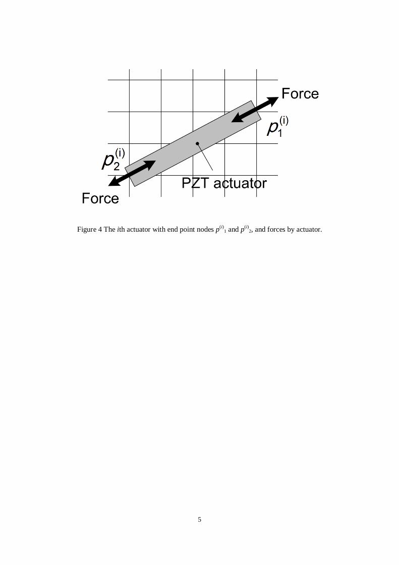
is number of actuators installed to the composites. An example of the actuator placement is suggested in Figure 4.
The forces F applied by the actuators are linear to the input voltage u and calculated by F = b2su. The length of a
PZT actuator is limited to l ≤ lmax (= 0.13 m). When the actuators cross each other, the design candidate has a
penalty imposed on its objective function giving it a very high objective value in the minimizing problem.
Laminated plates with different lay-ups give different natural frequencies and modes, but performing the
FEA repeatedly in the SGA process results in a heavy calculation load. To get around this, natural frequencies and
modal matrixes for all possible lay-ups are calculated in advance and a database containing information of lay-up
configurations and modal matrixes with lay-up indexes ηL is preliminarily developed. A design candidate with the
lay-up index ηL refers to the database and the modal matrix corresponding to ηL is used to calculate the objective
function by passing the FEA in the optimization process. The use of a database makes it possible to adapt the
quality of solutions to the aim of the optimization. If the elements in the database are limited to commonly used
lay-ups such as angle-ply, cross-ply and quasi-isotropic laminates, practical optimum solutions would be obtained.
Using fine increments for the orientation angle in each layer will result in solutions with higher controlled
performance than practical solutions since the problem has more degree-of-freedom than problem with a limited
number of possible solutions.

11
It is necessary to design the output feedback controller in each step of the SGA, but calculating the feedback
control law in every step also results in low calculation efficiency. The output feedback system is designed after
carrying out the simultaneous optimization where it is assumed that all states of the structures can be observed
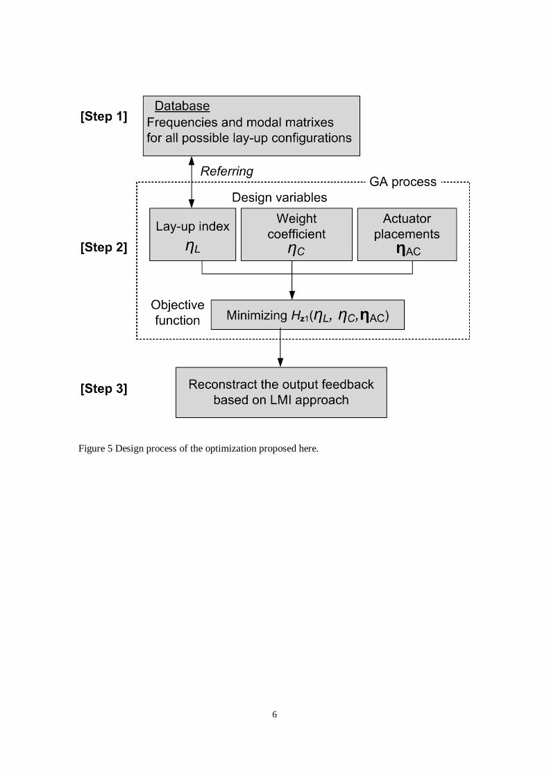
and a state feedback is available. The present optimization process is configured to follow a three-step procedure
and the flow chart of the optimization is shown in Figure 5.
[Step 1] Preparing the database containing natural frequencies and modal matrixes for all possible lay-up
configurations by repeated application of the FEA.
[Step 2] Assuming the state feedback, u = −Fq, performing the simultaneous optimization for the lay-up
configuration, the PZT actuator placement and the control system by the SGA.
[Step 3] Reconstructing the output feedback system with the dynamic compensator K(s) based on the LMI
approach.
RESULTS AND DISCUSSION
Optimization Results with Commonly Used Lay-up Configurations
First, calculated results were obtained with the database composed of commonly used lay-ups where limited
four fiber orientation angles 0°, 45°, -45° and 90° are used in the layer and a balanced rule constraint is imposed
on lay-up configurations. Lay-ups have the same number of 45° and -45° layers to avoid the in-plane coupling
between tensile and shearing deformation. The symmetric 8-layer plate [θ1/θ2/θ3/θ4]s is considered here and the
number of possible lay-up configurations for the database becomes 70. Two actuators are installed here, the
number of modes considered is the lowest eight, and the weight parameters Q and R, and the mode weight matrix
W10 are defined as
2
6 6 6 6 6 610
' , 10 ,
diag[1 1 10 10 10 10 10 10 ]
Q I R I
W

12
where the mode weights are imposed on the lowest two modes so as to suppress the first and second modes
vibration.
The resulting optimal actuator placements are shown in Figure 6 where the plate right edge is clamped and the
black strips represent the actuators and the design variable for control system qw and resulting performance
indexes Hz1 are listed in Table 2. The optimum lay-up is [0/0/0/0]s and agrees with the lay-up giving the highest
fundamental frequency for the cantilever plate. To confirm the validity of the optimization results, supplemental
results for other plates with commonly used lay-ups, cross-ply [0/90/0/90]s, angle-ply [45/-45/45/-45]s and in-
plane quasi-isotropic [0/45/-45/90]s are also shown in Figure 6 and Table 2. Here, other plates have their own
optimum actuator placements and control variable qw calculated by using the present approach but lay-ups are
specified in advance and are not included in the design variables. All the ends of the actuators are adjacent to the
clamped edges in Figure 6 and the lengths of all actuators are about 0.13 m (≈ lmax). The H2 norms with respect to
the control input for all plates are Hu = 0.1(= Hu, max). The [0/0/0/0]s plate indicates the lowest Hz1 = 6.76×10⁷ of
the four in Table 2 and this validates the optimization result.
Experimental Verification for the Present Technique
Calculated results are compared with experimental results to confirm the validity of the modeling and
controller design techniques. Figure 7 is an outline of the experimental set up and Figure 8 shows the smart
composite used in the vibration control experiment where the plate has the optimized [0/0/0/0]s lay-up and
actuator placement shown in Figure 6.
The plate is excited by an impulse hammer and the acceleration signal is measured by an accelerometer. The
feedback signal goes to a spectrum analyzer, and is also fed to a control PC with a control board through a low
pass filter which passes a signal lower than 20 kHz. Then, the optimally designed digital controller in the control
PC converts the feedback signal into the appropriate control input voltage, and the voltage amplified by a PZT
driver is applied to the PZT actuators where the amplification factor is set to 30. The sampling frequency of the
control system is 50 kHz.

13
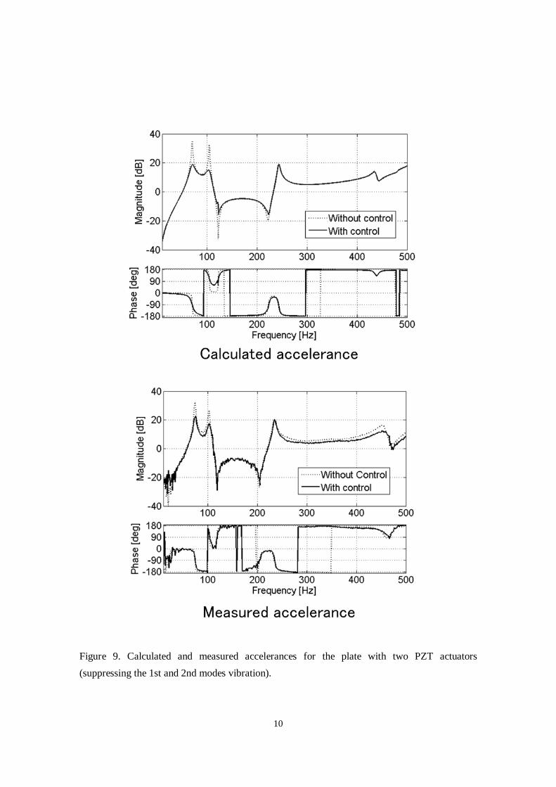
Calculated and measured accelerances are indicated in Figure 9. The amounts of reduction in both the first and
second peaks obtained in the experiments are about 10 dB, agreeing well with the calculated results although the
magnitude is a little smaller than the calculated results. This shows that the modeling method including neglect of
the PZT mass and stiffness effects and controller design techniques give valid results. The reduction of the
magnitude of peaks means the increase of damping performance for the structure, invoking a smoothed phase-
delay property in the vibration control frequency range. In Figure 9, compared with the results without control,
smoothed phase-delay curves are found at the resonance peaks in the calculated result with control, and this is
also seen for the experimental result with a little smoothness.
Optimization Results with Fine Increment Angles
The next optimization includes more degree-of-freedom for lay-up configurations and fine increment angles
are employed to prepare the database. The symmetric 8-layer plate [θ1/θ2/θ3/θ4]s is considered and the increments
in the fiber orientation angles are 15° for θ1 and θ2 (12 possible angle for each layer), and 45° for θ3 and θ4 (four
possible angles) in the range of −90° < θ ≤ 90° since the outer layers have a strong influence in determining the
bending stiffness of laminated plates and also in the frequency responses. Put differently, the outer layers are
considered more important to improve the control performance of the smart structures and they are assigned a
larger number of degree-of-freedom for the optimum solution. The total number of possible lay-up configurations
is 122×42 = 2304 and no constraints are imposed on the lay-up configurations.
The weight parameters Q and R, and the mode weight matrix W10 are defined for the lowest five modes as
2
6 610
, 10 ,
diag[1 1 1 10 10 ]
Q I R I
W
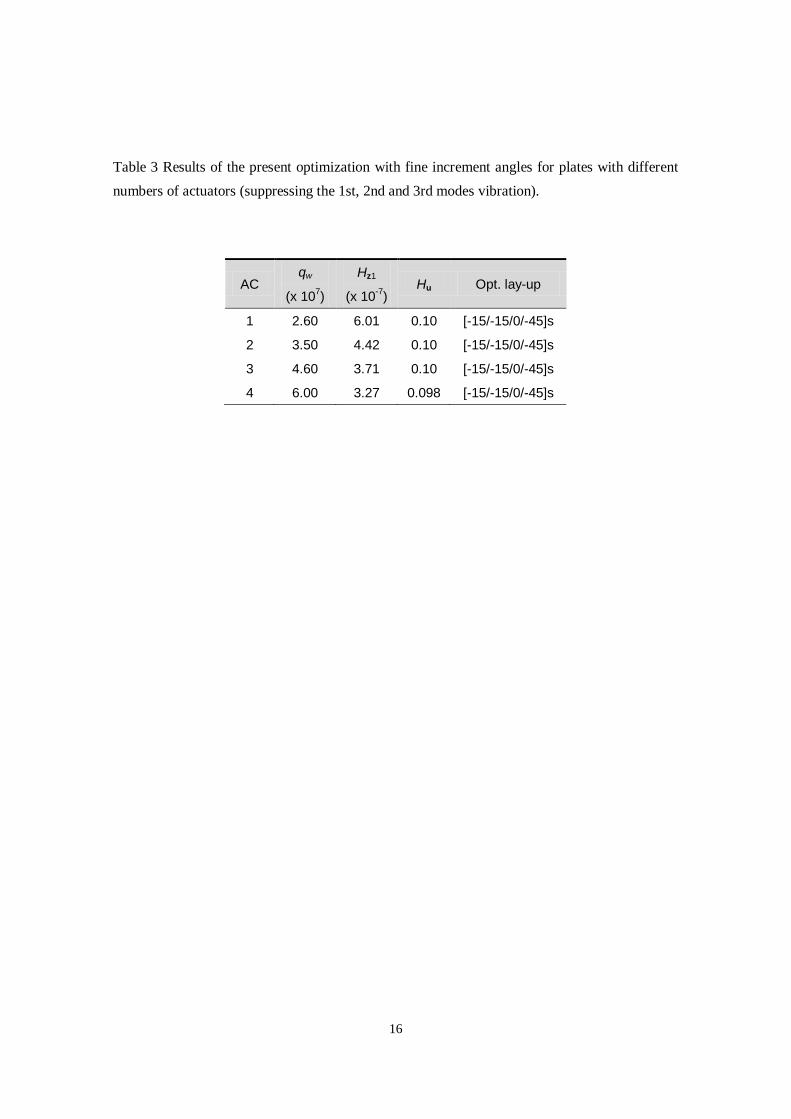
where the lowest three modes are weighted and controlled. The results are obtained for plates with the different
numbers of actuators (AC = 1, 2, 3 and 4) where AC is the number of actuators. The optimum actuator placements
are shown in Figure 10 and the obtained qw, Hz1, Hu, and optimized lay-ups are listed in Table 3.

14
All plates display the same optimized lay-ups [-15/-15/0/-45]s, showing that the optimum lay-up is insensitive
to the number of actuators with respect to vibration control, and the Hz1 decreases as the number of actuators
increases. As with the previous result which controls the lowest two modes, the [0/0/0/0]s plate also gives the
lowest Hz1 = 6.26×10⁻⁷ among the commonly used lay-ups [0/0/0/0]s, [0/90/0/90]s, [45/-45/45/-45]s and [0/45/-
45/90]s in the present problem suppressing the lowest three modes, and the optimized plate (AC = 2) gives Hz1 =
4.42×10⁻⁷. This is lower than the [0/0/0/0]s plate. The frequency characteristics for the [-15/-15/0/-45]s and
[0/0/0/0]s plates with AC = 2 are shown in Figure 11. In addition to suppression of the first and second modes
vibration, the third mode vibration is also suppressed well for the [-15/-15/0/-45]s plate compared with the
[0/0/0/0]s plate. To show the reason for this, the lowest three vibration mode shapes of the plate with [-15/-15/0/-
45]s and [0/0/0/0]s are shown in Figure 12 where the black lines (strips) show the actuators. The mode shapes of
the plates with the optimized lay-up [-15/-15/0/-45]s are skewed, affected by the -15° fiber orientation angles in
the outer two layers. Actuators for the plate with the optimum lay-up are arranged normal to the contour lines of
the first vibration mode and cross the nodal lines in the second and third modes. Those of the [0/0/0/0]s plate are
also arranged normal to the first and second modes but they do not cross the nodal lines of the third mode. This
causes the superior vibration control performance of the plates with the optimum lay-up [-15/-15/0/-45]s.
Laminated plates with different lay-ups invoke different mode shapes, and the simultaneous design of both the
lay-up configuration (mode shape) and the actuator placement results in activating the control input effectively in
the controlled structures. Therefore, it is concluded that the proposed multidisciplinary design optimization
technique has advantages over the conventional technique for fixed lay-ups with respect to the vibration control of
smart laminated composites.
CONCLUSIONS
The present study discussed a multidisciplinary design optimization of smart composite structures composed
of laminated composites and piezoelectric actuators. The design variables were the lay-up configuration of
composite plates, the placements of actuators and the control system based on the H2 control specifications. The

15
controlled smart composite was modeled by finite elements and the order was reduced using a modal coordinate
transformation technique. The simple genetic algorithm method was employed as a multidisciplinary design
optimizer.
The validity of the calculation technique was confirmed by comparing calculated results with experimental
results. The numerical results were for the plates with commonly used lay-ups and with lay-ups composed of fine
increment angles. The plates with the optimized lay-ups provide better control performance in terms of vibration
suppression than plates with other typical lay-ups. This allows the conclusion that the proposed multidisciplinary
design optimization technique is effective for the design of smart laminated composite structures.
ACKNOWLEDGMENTS
This work was supported by KAKENHI (22760164), and the first author expresses gratitude to Mr. Satoshi
Nakamura, who is a graduate student in Hokkaido University, for contributions to the experiments.

16
REFERENCES
Autio, M., 2000 "Determining the real lay-up of a laminate corresponding to optimal lamination parameters by genetic search," Structural and Multidisciplinary Optimization, 20: 301-310. Fukunaga, H. and Sekine, H., 1992 "Stiffness design method of symmetric laminates using lamination parameters," AIAA Journal, 30(11): 2791-2793. Gürdal, Z., Haftka, R. T. and Hajela, P., 1999, "Design and optimization of laminated composite materials," John Wiley & Sons, London Honda, S., Narita, Y. and Sasaki, K. 2009, "Discrete optimization for vibration fesign of composite plates by using lamination parameters," Advanced Composite Materials, 18: 297-314. Jha, A. K. and Inman, D. J, 2003, "Optimal sizes and placements of piezoelectric actuators and sensors for an inflated torus," Journal of Intelligent Material Systems and Structures, 14: 563-576. Kajiwara, I., Takahashi, M. and Arisaka, T., 2009, "Optimization of smart structure for improving servo performance of hard disk drive," Journal of System Design and Dynamics, 3(6): 906-917. Kang, Z. and Tong, L. 2008, "Integrated optimization of material layout and control voltage for piezoelectric laminated plates," Journal of Intelligent Material Systems and Structures, 19: 889-904. Matsuzaki, R. and Todoroki, A., 2007, "Stacking-sequence optimization using fractal branch-and-bound method for unsymmetrical laminates," Composite Structures, 78: 537-550 (2007). Narita, Y., 2003 "Layerwise optimization for the maximum fundamental frequency of laminated composite plate," Journal of Sound and Vibration, 263: 1005-1016. Ono, K. Kajiwara, I. and Ishizuka, S. 2007, "Piezoelectric and control optimisation of smart structures for vibration and sound suppression," International Journal of Vehicle Design, 43(1/2/3/4): 184-199. Quek, S. T., Wang, S. Y. and Ang, K. K. 2003, "Vibration control of composite plates via optimal placement of piezoelectric patches," Journal of Intelligent Material Systems and Structures, 14: 229-245 Rader, A. A., Afagh, F. F., Yousefi-Koma, A. and Zimcik, D. G., 2007, "Optimization of piezoelectric actuator configuration on a flexible fin for vibration control using genetic algorithms, " Journal of Intelligent Material Systems and Structures, 18: 1015-1033 Rao, A. K., Natesan, K., Bhat, M. S. and Ganguli, R., 2008, "Experimental demonstration of H∞ control based active vibration suppression in composite fin-tip of aircraft using optimally placed piezoelectric patch actuators," Journal of Intelligent Material Systems and Structures, 19: 651-669. Riche, L. R. and Haftka, R. T., 1993, "Optimization of laminate stacking sequence for buckling load maximization by genetic algorithm," AIAA Journal, 31(5):951–956.

17
Captures for figures and tables
Figures
Figure 1 The coordinate systems O – xyz for the laminated composite considered here.
Figure 2 Finite element model for the present composite plate, and impulse input and accelerometer attached
nodes used in calculations.
Figure 3 Block diagram of the present control system.
Figure 4 The ith actuator with end point nodes p(i)1 and p(i)
2, and forces by actuator.
Figure 5 Design process of the optimization proposed here.
Figure 6 Optimum actuator placements for plates with the optimum lay-up [0/0/0/0]s and specified lay-ups
[0/-45/45/90]s, [45/-45/45/-45]s and [0/90/0/90]s.
Figure 7 Constitution of the experimental set up
Figure 8 Placement of actuators, accelerometer and impulse input for the [0/0/0/0]s plate used in the
experiment.
Figure 9 Calculated and measured accelerances for the plate with two PZT actuators (suppressing the 1st and
2nd modes vibration).
Figure 10 Optimum actuator placements on the plates with optimized lay-ups and different numbers of
actuators.
Figure 11 Accelerances for the [-15/-15/0/-45]s (optimum) and [0/0/0/0]s plates with the optimum actuator
placements (AC = 2) (suppressing the 1st, 2nd and 3rd modes vibration).
Figure 12 The lowest three vibration modes and actuator placements for the [-15/-15/0/-45]s and [0/0/0/0]s
plates.
Tables
Table 1 Properties of PZT actuators used in this study.
Table 2 Results of the present optimization with commonly used lay-up configurations and the actuator
placement optimization for specified lay-up configurations (suppressing the 1st and 2nd modes
vibration).
Table 3 Results of the present optimization with fine increment angles for plates with different numbers of
actuators (suppressing the 1st, 2nd and 3rd modes vibration).

2
Figure 1 The coordinate systems O – xyz for the laminated composite considered here.

3
Figure 2 Finite element model for the present composite plate, and impulse input and accelerometer attached nodes used in calculations.

4
Figure 3 Block diagram of the present control system.
5
Figure 4 The ith actuator with end point nodes p(i)1 and p(i)
2, and forces by actuator.
6
Figure 5 Design process of the optimization proposed here.

7
Figure 6 Optimum actuator placements for plates with the optimum lay-up [0/0/0/0]s and specified lay-ups [0/-45/45/90]s, [45/-45/45/-45]s and [0/90/0/90]s.

8
Figure 7. Constitution of the experimental set up

9
Figure 8 Placement of actuators, accelerometer and impulse input for the [0/0/0/0]s plate used in the experiment.
10
Figure 9. Calculated and measured accelerances for the plate with two PZT actuators (suppressing the 1st and 2nd modes vibration).

11
Figure 10 Optimum actuator placements on the plates with optimized lay-ups and different numbers of actuators.

12
Figure 11 Accelerances for the [-15/-15/0/-45]s (optimum) and [0/0/0/0]s plates with the optimum actuator placements (AC = 2) (suppressing the 1st, 2nd and 3rd modes vibration).

13
Figure 12 The lowest three vibration modes and actuator placements for the [-15/-15/0/-45]s and [0/0/0/0]s plates.

14
Table 1 Properties of PZT actuators used in this study.
Material properties Values
Young’s modulus, E (GPa) 62
Poisson’s ratio, ν 0.32
Density, ρ (kg/m3) 7650
Thickness (m) 0.0005
Width (m) 0.015
Length (m) Variable (≤ 0.13)
Piezoelectric coefficients Values
d31 (m/V) -210 x 10-12
d33 (m/V) 472 x 10-12
d15 (m/V) 758 x 10-12

15
Table 2 Results of the present optimization with commonly used lay-up configurations and the actuator placement optimization for specified lay-up configurations (suppressing the 1st and 2nd modes vibration).
Lay-up Hz1 (x 10-7)
qw (x 107)
[0/0/0/0]s (opt.) 6.76 2.00
[45/-45/45/-45]s 26.2 0.400
[0/45/-45/90]s 9.79 1.30 [0/90/0/90]s 9.88 1.30
16
Table 3 Results of the present optimization with fine increment angles for plates with different numbers of actuators (suppressing the 1st, 2nd and 3rd modes vibration).
AC qw
(x 107)
Hz1
(x 10-7) Hu Opt. lay-up
1 2.60 6.01 0.10 [-15/-15/0/-45]s
2 3.50 4.42 0.10 [-15/-15/0/-45]s
3 4.60 3.71 0.10 [-15/-15/0/-45]s
4 6.00 3.27 0.098 [-15/-15/0/-45]s