Embed Size (px)
Citation preview

MULTI SLIDE - STACKING INSTALLATION INSTRUCTIONS

DOC-II-MS | Rev.5

INSTALLATION QUALITY CONTROL
PERFORMING SPECIFIC QUALITY CONTROL PROCEDURES ARE A CRITICAL PART OF COMPLETING ANY LaCANTINA DOORS INSTALLATION. WE RECOMMEND THE INSTALLER FILL OUT THE QUALITY CONTROL SHEET AND FILES AS A RECORD OF CORRECT AND COMPLETE INSTALLATION.
Customer: Phone:
Address:
Installer: Phone:
Where product was purchased:
Dealer Contact:
Receiving And Inspecting Of Product
Product was checked upon delivery at job site for correctness and was received as ordered Product was checked and free of damage Any damage or incorrectness was reported immediately to LaCantina Doors or the dealer where the
product was purchased Product was stored in a dry safe place where it could avoid damage Hardware box was located in frame box and all contents accounted for
Pre-Installation
General Contractor or homeowner has been consulted prior to installation of product Any wood product requiring finishing has been finished and tops and bottoms of doors were sealed
within 7 days of delivery Opening is configured correctly and any squaring or leveling issues have been identified Appropriate size header has been verified for use in opening Sill pan has been fabricated from appropriate material and is correctly located in the depth of the
rough opening Overhangs and other necessary design elements are present where appropriate Regarding installation of product, local codes and practices have been followed Section details have been reviewed and understood Problems pertaining to existing windows, doors and/or rough openings have been reported to a
responsible party and have been resolved and documented All safety issues related to unsafe site conditions and hazardous materials have been properly
addressed and resolved

Installation
All materials used have been checked for compatibility Weather Resistant barrier and flashing were coordinated with contractor or authority on site Correct orientation of system has been identified Sill condition is understood and necessary weep system is in place where standard Weather Resistant
sill has not been applied Frame has been sealed and joined at all points indicated in instructions Opening checked for correct dimensions Frame is installed at correct depth within the opening Frame has been installed square, level and plumb Where required, plastic shims were utilized under sill Jambs were shimmed to prevent rolling Installation holes have been prepared correctly Sealant was applied to sill installation holes prior to inserting screws Correct fastener placement has been followed as directed by manufacturer Proper operation and adjustment has been performed Product was installed as recommended by the Manufacturer
Final Check of Installation
Frame has been checked for level, square and plumb All adjustments have been made so that proper reveals are present and
product is operating as designed Weep holes have been checked and free of obstruction and debris All trash has been discarded All hardware has been installed correctly and checked for proper operation Product has been closed and locked and recommended to not be used as thoroughfare by other
trades. Product is protected from damage Final inspection of weather proofing and operation has been performed Job has been turned over to contractor or other responsible party with approval Homeowners Kit has been given to contractor or homeowner Other
LaCantina Doors recommends that installers return to site and perform a final check of installation. Namely that the header has not sagged under structure settlement and/or weight and necessary adjustments have been made prior to installation of exterior siding/stucco and interior finishes.
Where applicable, each of the items checked above have been properly reviewed, verified and completed as part of my field quality control check prior to turning over the job to the responsible party/approving authority.
Installer’s Signature: Date:
The items checked above were completed as part of the installer’s quality control process. My signature indicates that the installation was completed to my satisfaction and/or direction
Responsible Party: Date:
THANK YOU FOR PURCHASING LaCANTINA DOORS.
INSTALLATION OF LaCANTINA MULTI SLIDE DOOR SYSTEMPLEASE READ INSTRUCTIONS CAREFULLY BEFORE ASSEMBLING DOOR SYSTEM
THE FOLLOWING INSTRUCTIONS ARE TO BE USED AS A GUIDELINE ONLY. JOB-SITE SPECIFIC APPLICATIONS MAY REQUIRE CHANGES IN ASSEMBLY AND INSTALLATION OF THIS PRODUCT. NO WARRANTY IS PROVIDED FOR INSTALLATION.
LaCANTINA DOORS INSTALLATION AND WARRANTY INFORMATIONTHE FOLLOWING INSTRUCTIONS ARE TO BE USED FOR LaCANTINA DOORS ASSEMBLY AND INSTALLATION.
A COPY OF THE LIMITED WARRANTY AND MAINTENANCE REQUIREMENTS IS INCLUDED IN THIS PACKAGE AND MUST BE READ PRIOR TO INSTALLATION. WARRANTY AND MAINTENANCE REQUIREMENTS CAN ALSO BE FOUND AT LaCANTINADOORS.COM.
FAILURE TO FOLLOW FACTORY ASSEMBLY, INSTALLATION AND MAINTENANCE INSTRUCTIONS WILL VOID THE MANUFACTURER’S LIMITED WARRANTY. ALL VISIBLE DEFECTS MUST BE REPORTED BEFORE INSTALLATION AND FINISHING.
THESE INSTRUCTIONS ARE THE PROPERTY OF LaCANTINA DOORS, INC. AND MAY NOT BE DUPLICATED, ALTERED OR DISTRIBUTED FOR ANY PURPOSE WHATSOEVER WITHOUT THE EXPRESS WRITTEN PERMISSION OF LaCANTINA DOORS, INC.

THE MOST IMPORTANT CRITERIA FOR A SUCCESSFUL JOB IS A SQUARE OPENING, A RIGID HEAD AND A CLEAN TRACK.IT IS RECOMMENDED THAT A LaCANTINA DOOR SYSTEM IS INSTALLED WITH AT LEAST TWO PEOPLE; LARGER SYSTEMS WILL REQUIRE MORE PEOPLE.
THE INSTALLATION OF YOUR LCD MULTI SLIDE DOOR SYSTEM REQUIRES THAT THE SILL, HEAD AND JAMBS ARE PERFECTLY STRAIGHT AND SQUARE. THE SILL SHOULD BE INSTALLED FLAT AND STRAIGHT, ENSURING THAT THERE IS NO UPWARD BOWING. THE FRAME SHOULD BE CHECKED FOR SQUARE AND TWIST.
ENSURING YOUR FRAME IS SQUARE, PLUMB, AND LEVEL WILL ALLEVIATE PROBLEMS IN THE FUTURE.
INSTALLATION OF FLASHING TO ENSURE A PROPER WATER SEAL IS THE RESPONSIBILITY OF THE INSTALLER. LOCAL CODES AND BUILDING PRACTICES SHOULD BE APPLIED.
* IMPORTANT NOTICE* READ PRIOR TO INSTALLATION.A LaCANTINA SYSTEM IS A SPECIALTY PRODUCT THAT YOU CANNOT ASSUME TO BE A STANDARD INSTALLATION OF A TYPICAL DOOR OR WINDOW.
REFER TO YOUR LaCANTINA DOORS ORDER FORM TO REFERENCE CONFIGURATION, AND REVIEW APPLICABLE SECTION DETAIL TO VERIFY FRAME ORIENTATION IN RELATION TO THE OPENING
LaCANTINA PRODUCTS SHOULD BE INSTALLED WITH OVERHEAD PROTECTION TO PREVENT THE EFFECTS OF SHEETING WATER FROM ABOVE. MULTIPLE INTERIOR WATER BARRIER LEGS ARE OFFERED & THE CORRECT HEIGHT SHOULD BE UTILIZED DEPENDING ON SITE SPECIFIC WATER EXPOSURE
WE RECOMMEND THAT A PROFESSIONAL WATERPROOFING CONSULTANT BE USED TO PROPERLY INTEGRATE OUR PRODUCTS INTO THE WEATHER BARRIER OF THE WALL STRUCTURE.
** LaCANTINA DOORS RECOMMENDS TOPS AND BOTTOMS OF DOORS WITH EXPOSED WOOD BE SEALED PRIOR TO INSTALLATION.
TABLE OF CONTENTS
RECOMMENDED TOOLS AND MATERIALS 1
PARTS LIST 2
STEP ONE - PRE-DRILL FRAME COMPONENTS 5
STEP TWO - APPLY SEALANT 8
STEP THREE - JOINING FRAME 9
STEP FOUR - INSTALLING FRAME 10
STEP FIVE - INSTALLING DOORS 12
STEP SIX - FINAL ADJUSTMENTS 17
STEP SEVEN - INSERT COVER PLATES 21
STEP EIGHT - OPENING AND CLOSING DOORS 22
* INSTALLING FLUSH SILL AND SILL PAN 23
** ADDITIONAL DRILL POINTS FOR LARGER TRACKS 24
*** ALL OPERABLE SYSTEMS ADDENDUM 25
WARRANTY 28


1
12” x #2 Phillips Screwdriver 6” #2 Square Drive &6” #2 Phillips Extension Bit
6’ Spirit Level or Laser Level
SealantCounter Sink
Wood & Plastic ShimsSill Pan
Flashing
Drill / SDS Hammer Drill& SDS Drill Bit
Drill Bit Index Set
Foam Filler
Cross String
Safety Goggle/Glasses
Blue Painters Tape
Rubber Mallet5/16” Ratchet Wrench3/4” Backer Rod
12” x #2 Flathead Screwdriver
Story Pole
RECOMMENDED TOOLS
Here are recommended tools and materials which are not supplied, but are necessary to install your LaCantina Doors’ Pleated Screen.
NOTE: Ensure all sealants and materials used are compatible.
3

2
DOOR KIT | PARTS LIST Quantity of parts supplied as required per system
PART Description
Glazed Doors with Hardware
Top Track Assembly
Bottom Track Assembly
Jamb Legs Assembly
Bull Nose
Jamb Cover Plates
Head Cover Plates
Channel Sill Cap
Key Set
3
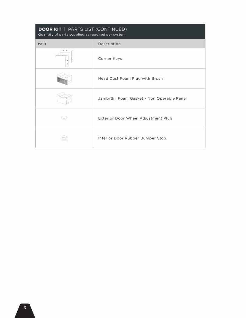
DOOR KIT | PARTS LIST (CONTINUED) Quantity of parts supplied as required per system
PART Description
Corner Keys
Head Dust Foam Plug with Brush
Jamb/Sill Foam Gasket - Non Operable Panel
Exterior Door Wheel Adjustment Plug
Interior Door Rubber Bumper Stop

4
SCREW KIT | PARTS LIST Quantity of parts supplied as required per system
PART Description
1 1/2” Frame Sill Assembly Screw
#10 x 3” Pan Top Track and Jamb Install Screw
#10 Flat 1/2” Corner Key Installation Screw
#10 x 2” Flat Sill Exterior Screw (wood)
#10 x 2” Flat Sill Exterior Screw (concrete)
#10 x 2” Pan Sill Interior Screw
#10 x 3” Flat Keeper Screw
#12 Hex Head Fixed Panel Screw
1
2
3
4 a
4 b
5
6
7

5
STEP 1 Pre-Drill Frame Components
Step 1
Step 2
4 1/2”
20”
4 1/2”
20”
a. Bottom Track Using 13/64” drill bit, pre-drill interior and exterior install holes in bottom track locking channel. One screw to be placed 4 1/2” from both ends. Additional screws spaced every 20” or as required by local building code.NOTE: Exterior drill holes need to be countersunk to allow for bull nose assembly.

6
4 1/2”
20”
4 1/2”
20”
b. Top Track - Drill PointUsing 13/64” drill bit, pre-drill install holes in top track. Holes should be pre-drilled 4 1/2” from edge and evenly spaced every 20”. Use guide line in center of top track for hole placement or as required by local building code.NOTE: Tracks with a depth of 4 or more will require additional drill points, refer to page 24 for additional drill points.NOTE: Automated systems will require drill holes to be countersunk in primary track only. Non countersunk screws will interfere with the automation belt.
NOTE: Head and jamb installation hole locations to be determined by framing conditions. It may be necessary to change location to contact framing.

7
Even
Interior InteriorExterior
Even
4 1
/2”
4 1
/2”
c. Jamb Leg Locate guide line.
NOTE: Both jamb legs to be pre-drilled.
Additional screws will be required for units over 7ft.
8
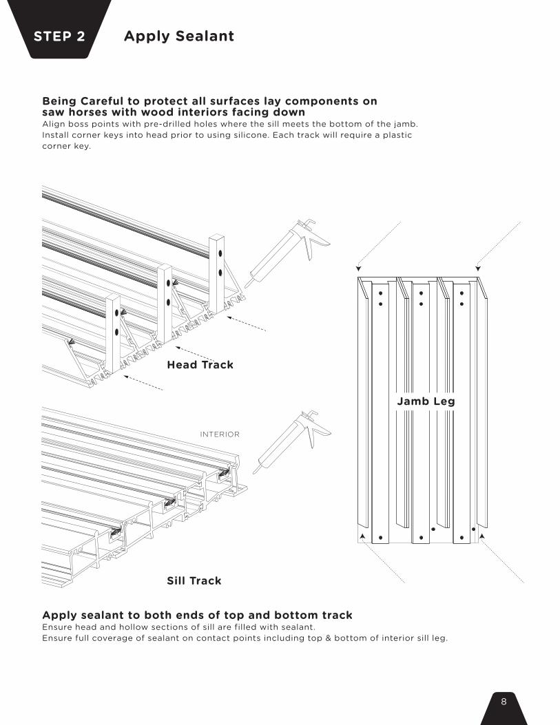
STEP 2 Apply Sealant
Apply sealant to both ends of top and bottom track Ensure head and hollow sections of sill are filled with sealant.Ensure full coverage of sealant on contact points including top & bottom of interior sill leg.
Head Track
Sill Track
INTERIOR
Jamb Leg
Being Careful to protect all surfaces lay components on saw horses with wood interiors facing downAlign boss points with pre-drilled holes where the sill meets the bottom of the jamb.Install corner keys into head prior to using silicone. Each track will require a plastic corner key.

9
STEP 3 Joining Frame
C C
B
B
A
A
D D 1
1
1
1
1
1
1
1 1
3 3
3 3
3 3
3 3
3
3
3
3
3 3
3 3
3 3
3 3
3
3
3
3
NOTE: Seal and flush wood components
NOTE: Connect both jambs to sill at the same time
10
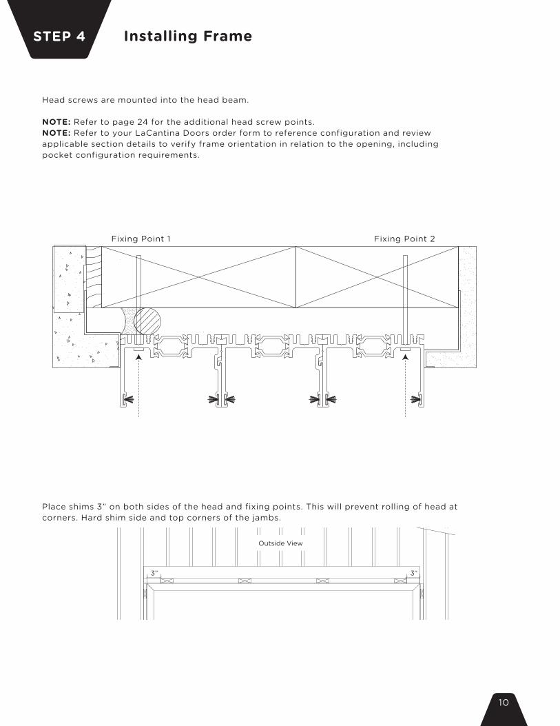
Installing FrameSTEP 4
Head screws are mounted into the head beam.
NOTE: Refer to page 24 for the additional head screw points.NOTE: Refer to your LaCantina Doors order form to reference configuration and review applicable section details to verify frame orientation in relation to the opening, including pocket configuration requirements.
Place shims 3” on both sides of the head and fixing points. This will prevent rolling of head at corners. Hard shim side and top corners of the jambs.
Fixing Point 1 Fixing Point 2
Outside View
3” 3”

11
+ – 1/8”
Outside View
2 2 22 2 2 2
2 2 22
2
2
2
2
2
4 & 5 4 & 5 4 & 5 4 & 5 4 & 5 4 & 5 4 & 5 4 & 5 4 & 5 4 & 5
Prior to installing sill into floor verify the finish floor height and check for where the high point of the subfloor is located.
• Stand frame into opening and screw frame to base, studs and header Use laser or cross strings and a level to ensure frame is plumb, square and level.
• Attach sill first, using either wood or concrete screws supplied. Apply silicone to bottom track install holes prior to fastening also apply silicone to screw head once fastened 4a if system is mounted into wood on the exterior 4b if system is mounted into concrete on the exterior 5 is mounted into wood on the interior
• Attach jamb leg, using supplied screws Ensure jamb legs are hard shimmed at fixing points to prevent “rolling” of frame. • Attach top track to header using supplied screws Shim to prevent from rolling. NOTE: Jamb and head installation screws supplied with the system are for wood framing and header only. Headers made from other materials such as steel should be fixed with alternate fasteners.
12
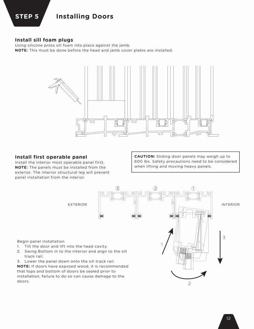
Installing DoorsSTEP 5
Begin panel installation1. Tilt the door and lift into the head cavity.2. Swing Bottom in to the interior and align to the sill
track rail.3. Lower the panel down onto the sill track rail.NOTE: If doors have exposed wood, it is recommended that tops and bottom of doors be sealed prior to installation, failure to do so can cause damage to the doors.
1
3
2
123
EXTERIOR INTERIOR
Install first operable panelInstall the interior most operable panel first. NOTE: The panels must be installed from the exterior. The interior structural leg will prevent panel installation from the interior.
CAUTION: Sliding door panels may weigh up to 600 lbs. Safety precautions need to be considered when lifting and moving heavy panels.
Install sill foam plugsUsing silicone press sill foam into place against the jamb. NOTE: This must be done before the head and jamb cover plates are installed.

13
NOTE: Before sliding adjust door wheels to allow free movement to avoid damage to the sill. Perform final adjustments when all doors are installed.
EXTERIOR
INTERIOR

14
Install additional operable panelsRepeat steps on page 12, installing each panel working your way to the exterior most panel. Place next panel in the center of the door aligned with the back stile of the previously installed panel. Repeat until all operable panels are installed.
EXTERIOR
INTERIOR
1
3
2
123
EXTERIOR INTERIOR
15
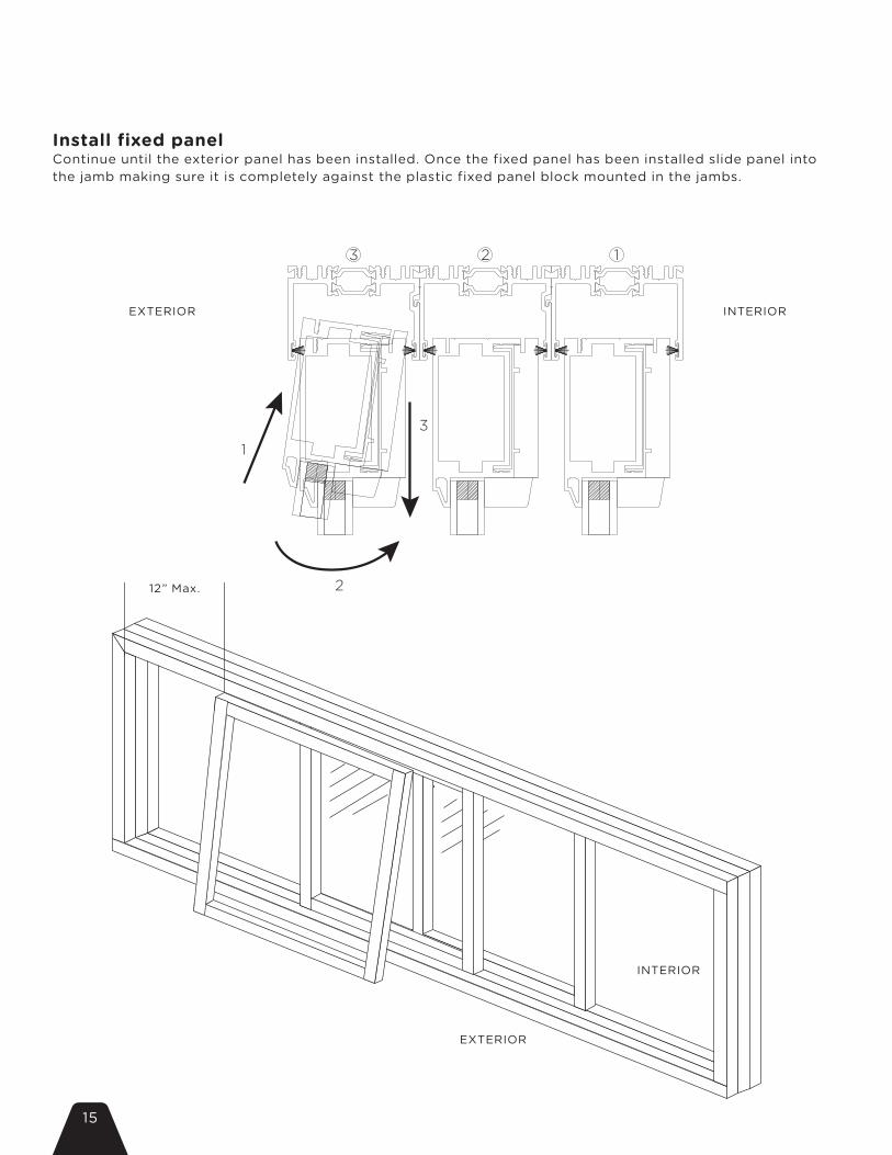
Install fixed panelContinue until the exterior panel has been installed. Once the fixed panel has been installed slide panel into the jamb making sure it is completely against the plastic fixed panel block mounted in the jambs.
EXTERIOR
12” Max.
INTERIOR
1
3
2
123
EXTERIOR INTERIOR

16
Attach fixed panel to jambMount door to fixed panel block using supplied fasteners and a 5/16” ratchet wrench.1. Locate pre-drilled fastening points and align to pre-drilled holes in the
fixed panel block.2. Using supplied fasteners attach jamb to fixed panel.3. Repeat until all fasteners have been installed, typically there will be 3
mounting points.- IF ALL OPERABLE SKIP THIS STEP.
EXTERIOR
INTERIOR
7
17
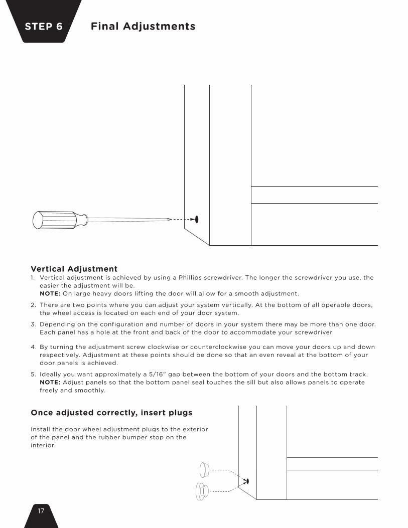
Vertical Adjustment1. Vertical adjustment is achieved by using a Phillips screwdriver. The longer the screwdriver you use, the
easier the adjustment will be. NOTE: On large heavy doors lifting the door will allow for a smooth adjustment.
2. There are two points where you can adjust your system vertically. At the bottom of all operable doors, the wheel access is located on each end of your door system.
3. Depending on the configuration and number of doors in your system there may be more than one door. Each panel has a hole at the front and back of the door to accommodate your screwdriver.
4. By turning the adjustment screw clockwise or counterclockwise you can move your doors up and down respectively. Adjustment at these points should be done so that an even reveal at the bottom of your door panels is achieved.
5. Ideally you want approximately a 5/16” gap between the bottom of your doors and the bottom track. NOTE: Adjust panels so that the bottom panel seal touches the sill but also allows panels to operate
freely and smoothly.
Once adjusted correctly, insert plugs
Install the door wheel adjustment plugs to the exterior of the panel and the rubber bumper stop on the interior.
STEP 6 Final Adjustments

18
6
6
6
a. Install and adjust keeper on lock
EXTERIOR INTERIOR
KEEPER LOCK
Additional Installation
1. Adjust doors to the correct working height. NOTE: Failure to do this prior to installing the keeper will cause the lock not to line up properly and will
result in a misalignment in the locking system.
2. Center 2 point lock on edge of door should align with center of keeper. NOTE: The keeper has a scribed link that indicates the center of the keeper.
3. Once located and adjusted pre-drill additional holes with a 5/32” drill to top and bottom mounting locations of the keeper, install with #6 keeper screw.
4. Remove screw from middle point and replace with #6 keeper screw. NOTE: Hole may need to be redrilled to extend the length of the hole to fit the keeper screw.
5. Screws should mount and secure into the rough frame. NOTE: Shims may need to be used so the frame does not bow.

19
b. Attach channel capsSnap in channel caps per system configuration using a rubber mallet as required. NOTE: Do not install if doors will need to pulled from frame after initial installation, this can cause damage to the doors and sill.
- IF ALL OPERABLE SKIP TO STEP C.
c. Install bull nose1. Silicone top and bottom of bull nose connection points.
NOTE: Ensure silicone does not interfere with weep drainage holes.2. At an angle place bull nose hook into sill catch.3. Rotate bull nose down and back.4. With a block of wood and a rubber mallet starting at one end, tap
the bull nose snapping it into place.
2
3
4
20
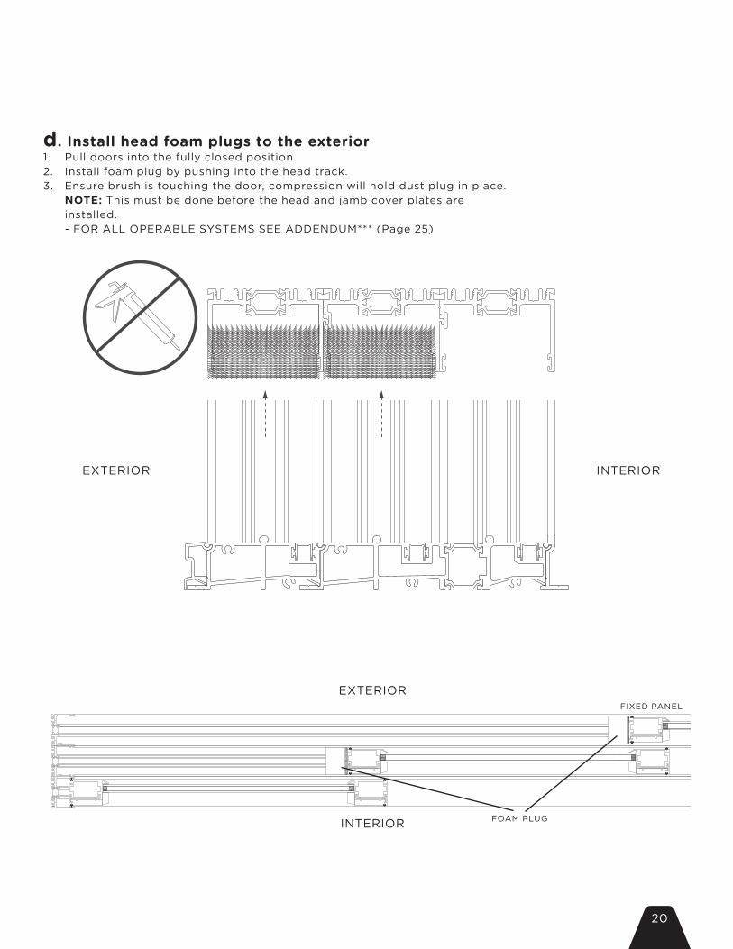
d. Install head foam plugs to the exterior1. Pull doors into the fully closed position.2. Install foam plug by pushing into the head track.3. Ensure brush is touching the door, compression will hold dust plug in place.
NOTE: This must be done before the head and jamb cover plates are installed.- FOR ALL OPERABLE SYSTEMS SEE ADDENDUM*** (Page 25)
EXTERIOR
EXTERIORFIXED PANEL
FOAM PLUGINTERIOR
INTERIOR

21
Insert Cover PlatesSTEP 7
a. Snap jamb cover plates into placeInsert the milled top portion into the head. Using a rubber mallet and wood block gently hammer the cover plates into place, starting at the base of the sill working up towards the head. Match numbered plates with configuration, refer to page 27.
b. Snap head cover plates into placeUsing a rubber mallet and wood block gently hammer the cover plates into place, starting at the corner where the jamb meets the head.NOTE: Failure to start the cover plate at corner of the jamb can result in a gap between the jamb and head cover plates.- FOR ALL OPERABLE THERE WILL BE NO HEAD COVER PLATES.
EXTERIOR INTERIOR
EXTERIOR 3
3
3
2
2
2
INTERIOR
22
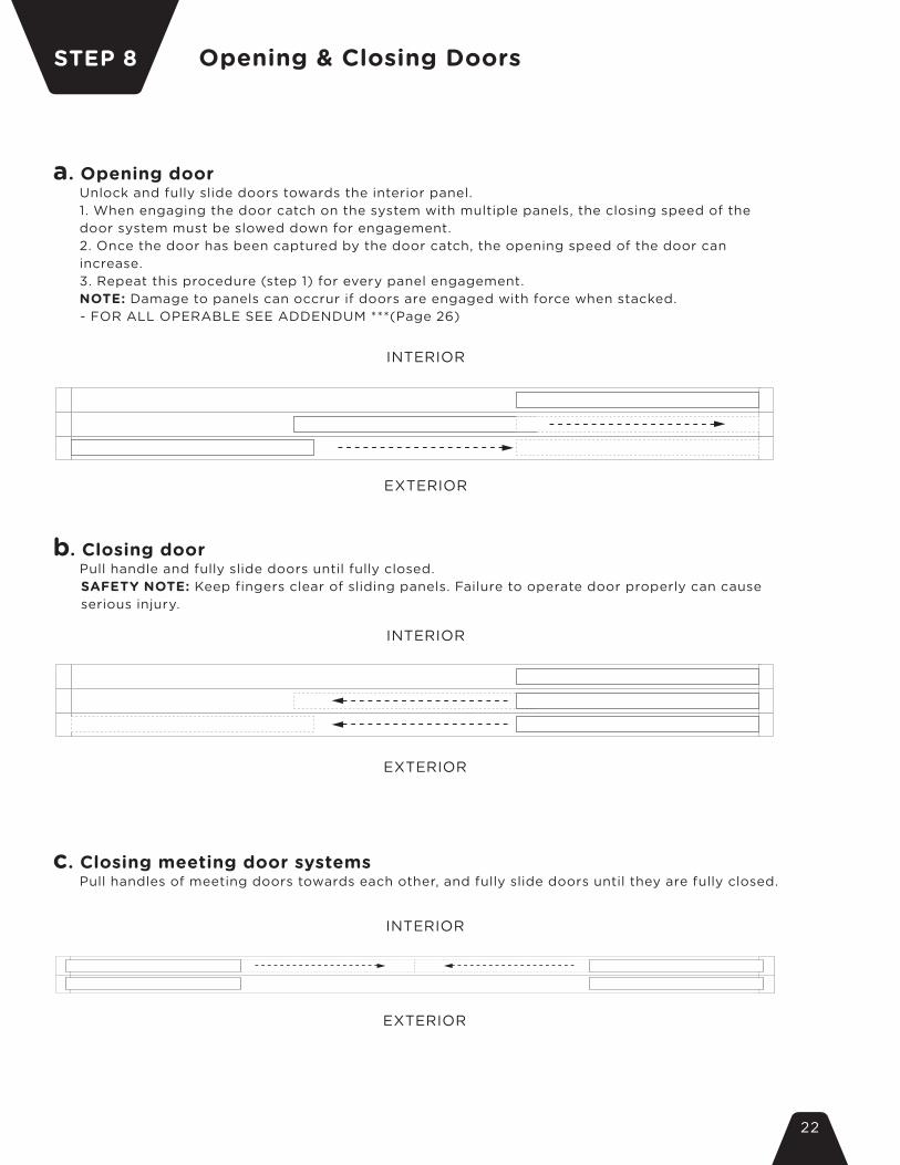
Opening & Closing DoorsSTEP 8
a. Opening doorUnlock and fully slide doors towards the interior panel.1. When engaging the door catch on the system with multiple panels, the closing speed of the door system must be slowed down for engagement.2. Once the door has been captured by the door catch, the opening speed of the door can increase.3. Repeat this procedure (step 1) for every panel engagement.NOTE: Damage to panels can occrur if doors are engaged with force when stacked.
- FOR ALL OPERABLE SEE ADDENDUM ***(Page 26)
b. Closing doorPull handle and fully slide doors until fully closed.
SAFETY NOTE: Keep fingers clear of sliding panels. Failure to operate door properly can cause serious injury.
c. Closing meeting door systemsPull handles of meeting doors towards each other, and fully slide doors until they are fully closed.
EXTERIOR
INTERIOR
INTERIOR
EXTERIOR
INTERIOR
EXTERIOR
23
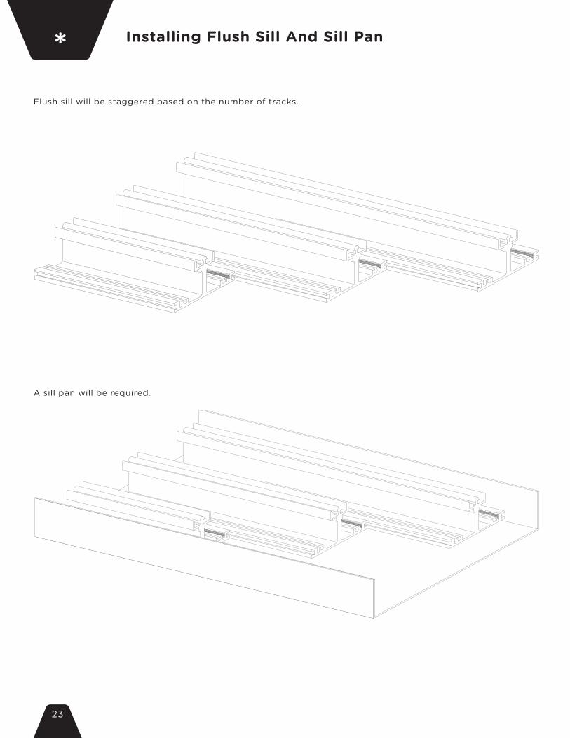
Installing Flush Sill And Sill Pan*Flush sill will be staggered based on the number of tracks.
A sill pan will be required.

24
Additional Drill Points For Larger Tracks**Head tracks with more than 3 tracks will require additional drill points. A 4 track system will have 3 drill points and a 5 or 6 track system will have 4 drill points.

25
EXTERIOR
EXTERIOR
FOAM PLUGINTERIOR
INTERIOR
Head Track Dust Cap installation:At installation step 6-d, head foam plugs will be installed different than standard instructions. 1. Slide doors to closed position2. Apply a dab of silicon inside the top of the head track directionally above the stile of door where they meet. See Drawings.3. Slide foam Dust Cap into head track where silicon was just applied with brush facing down.4. Foam Dust Cap should be slid into track so that the outer edge of the foam aligns with the edge of the door keeping the cap in line with the stile. Refer to drawing A below.5. Skip Step 7 (Installation of Cover Plates)
All Operable Systems Addendum***
a.

26
a. Opening door - All OperableUnlock and fully slide doors towards either direction.NOTE: All panels are identical from left to right viewed from the exterior.
b. Closing door - All OperablePull handle and fully slide doors until fully closed.
Follow Home Owners Manual for safe operation. Failure to follow these directions could result in damage to active latches.
SAFETY NOTE: Keep fingers clear of sliding panels. Failure to operate door properly can cause serious injury.
EXTERIOR
INTERIOR
INTERIOR
EXTERIOR
INTERIOR
EXTERIOR
PRIMARY 3
PRIMARY 3
PRIMARY 1
PANEL 2
PANEL 3
PANEL 2
PANEL 1
PANEL 2
PANEL 1
27
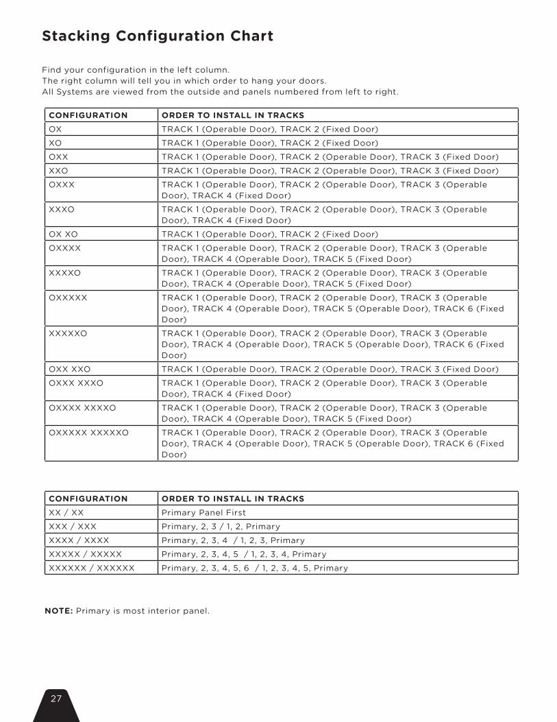
Stacking Configuration Chart
CONFIGURATION ORDER TO INSTALL IN TRACKSOX TRACK 1 (Operable Door), TRACK 2 (Fixed Door)
XO TRACK 1 (Operable Door), TRACK 2 (Fixed Door)
OXX TRACK 1 (Operable Door), TRACK 2 (Operable Door), TRACK 3 (Fixed Door)
XXO TRACK 1 (Operable Door), TRACK 2 (Operable Door), TRACK 3 (Fixed Door)
OXXX TRACK 1 (Operable Door), TRACK 2 (Operable Door), TRACK 3 (Operable Door), TRACK 4 (Fixed Door)
XXXO TRACK 1 (Operable Door), TRACK 2 (Operable Door), TRACK 3 (Operable Door), TRACK 4 (Fixed Door)
OX XO TRACK 1 (Operable Door), TRACK 2 (Fixed Door)
OXXXX TRACK 1 (Operable Door), TRACK 2 (Operable Door), TRACK 3 (Operable Door), TRACK 4 (Operable Door), TRACK 5 (Fixed Door)
XXXXO TRACK 1 (Operable Door), TRACK 2 (Operable Door), TRACK 3 (Operable Door), TRACK 4 (Operable Door), TRACK 5 (Fixed Door)
OXXXXX TRACK 1 (Operable Door), TRACK 2 (Operable Door), TRACK 3 (Operable Door), TRACK 4 (Operable Door), TRACK 5 (Operable Door), TRACK 6 (Fixed Door)
XXXXXO TRACK 1 (Operable Door), TRACK 2 (Operable Door), TRACK 3 (Operable Door), TRACK 4 (Operable Door), TRACK 5 (Operable Door), TRACK 6 (Fixed Door)
OXX XXO TRACK 1 (Operable Door), TRACK 2 (Operable Door), TRACK 3 (Fixed Door)
OXXX XXXO TRACK 1 (Operable Door), TRACK 2 (Operable Door), TRACK 3 (Operable Door), TRACK 4 (Fixed Door)
OXXXX XXXXO TRACK 1 (Operable Door), TRACK 2 (Operable Door), TRACK 3 (Operable Door), TRACK 4 (Operable Door), TRACK 5 (Fixed Door)
OXXXXX XXXXXO TRACK 1 (Operable Door), TRACK 2 (Operable Door), TRACK 3 (Operable Door), TRACK 4 (Operable Door), TRACK 5 (Operable Door), TRACK 6 (Fixed Door)
Find your configuration in the left column.The right column will tell you in which order to hang your doors.All Systems are viewed from the outside and panels numbered from left to right.
CONFIGURATION ORDER TO INSTALL IN TRACKSXX / XX Primary Panel First
XXX / XXX Primary, 2, 3 / 1, 2, Primary
XXXX / XXXX Primary, 2, 3, 4 / 1, 2, 3, Primary
XXXXX / XXXXX Primary, 2, 3, 4, 5 / 1, 2, 3, 4, Primary
XXXXXX / XXXXXX Primary, 2, 3, 4, 5, 6 / 1, 2, 3, 4, 5, Primary
NOTE: Primary is most interior panel.

28
Limited WarrantyThis express limited warranty is effective for product manufactured by LaCantina Doors, Inc. (“LaCantina”) after March 1, 2011, extends to all original end users and is not transferable.
WARRANTY COVERAGESubject to the conditions, exclusions and limitations of this limited warranty, we warrant our glass and components below will be free from defects in materials and workmanship which would render the product unserviceable or unfit for ordinary recommended use from the date of shipment for the following time periods:
Glass – We warrant insulated glass against failure of the air seal and that each unit will be free from material obstruction of vision as a result of fogging or film formation on the internal surfaces. We warrant laminated glass against delamination resulting in materially obstructed vision through the laminated glass. All glass is warranted for a period of twenty (20) years.
Component Finishes – LaCantina standard aluminum paint finish is warranted for a period of ten (10) years against defects resulting in cracking, peeling and other loss of adhesion. Optional and Custom color paint finishes are warranted for a period of ten (10) years unless in coastal environments (within three (3) miles of a sea coast or salt water, which will be warranted for a period of one (1) year). Anodized finishes are warranted for a period of three (3) years unless in coastal environment (within three (3) miles of a sea coast or salt water which will be warranted for a period of one (1) year). LaCantina standard vinyl is warranted for a period of ten (10) years against manufacturing defects which results in rotting, cracking, warping, pitting, corroding, peeling, blistering, or non-uniform color.
Hardware and Components – Folding system and swing door carriers, pivots, surface mounted locks and hinges will be warranted for a period of ten (10) years. Multipoint and locking mechanisms will be warranted for a period of five (5) years. Sliding system hardware components including multipoint lock mechanisms and rolling hardware will be warranted for a period of ten (10) years.
All hardware products should be cleaned and maintained as recommended below and as frequently as necessary. Hardware in coastal and salt water environments should be cleaned and maintained every three (3) months as a minimum and more frequently to prevent buildup of salt water or corrosive residue. In event of a warranty claim user must be able to present maintenance schedule as recommended below.
Weather Seals - All seals are warranted for a period of ten (10) years. Systems should be adjusted as per our recommendation and according to variances in site conditions so as not to put undue stress and/or pressure on seals during operation.
Screens – When installed to the interior of a residence or place of business, both pleated and non-pleated screens are warranted for a period of five (5) years. Exterior application of screen is not recommended. Screens easily dislodge from the track if fallen on and are not designed to prevent falls. Export Limitation - The maximum warranty period for any product used outside of the United States is two (2) years on glass and components and ten (10) years on folding system hardware.
WARRANTY CONDITIONS, EXCLUSIONS AND LIMITATIONSThis warranty is limited to defects in materials and workmanship and expressly excludes damage or defects caused by or arising from:
• Minor glass imperfections which do not impair structural integrity or obscure normal vision, including slight bubbles, lines, surface imperfections or discolorations; any imperfections in the glass not detected from within ten feet whilst looking through the glass as per the guidelines established by federal standard ASTM C 1036-01; cracked or broken glass or damage resulting from accident including from impact or wind pressure, misuse or abuse; glass with films or coatings applied; and failure of insulated glass seal due to contact of finishing product.
• Warp beyond one (1) year from date of shipment for any 3’3” wide by 8’0” high by 1 3/4”, or smaller door panel, which does not exceed 1/4” in the plane of the door panel itself and that adversely affect the normal functioning of the door system; door panels wider and/or higher are not guaranteed for warp; warp, bow or misalignment of frame components that can be straightened during typical installation or occurring beyond one (1) year from date of shipment;
• Structural integrity issues, including improper sizing of header and movement or sagging of framing or the header and flaws in building design and construction; improper installation not in conformance with our installation instructions; alignment of meeting panels; slight expansion or contraction due to varying environmental conditions; and panel movement (shrinkage) of 1/4” or less due to temperature and humidity;
- Damage as a result of improper or lack of adjustment• Water or water intrusion or air infiltration; design of an appropriate flashing system; failure to provide an

29
• adequate overhang and to prevent the effects of sheeting water from above; doors with ADA compliant, guide channel or zero-step sills, inswing, zero post corner and curved systems; and product installed in high moister environments or in structures that fail to allow for the proper management of drainage or moisture;
- Condensation on interior of product as a result of excess humidity.• Uniform color fade of vinyl material as a result of surface exposure to ultraviolet (sun) light or non-uniform
color fading, discoloration, darkening and/or chalking as a result of unequal surface exposure to ultraviolet light and elements. Damage caused by all external factors including harmful fumes, chemicals, distortion or warping due to building head, excessive temperature exposure or unusual heat sources including outdoor grills, interior and exterior reflection from roofs, windows, walls, window coverings or other surfaces, oxidation, staining or mildew, accident, abuse, misuse, and neglect.
• Accident, misuse, abuse, failure to follow the care and maintenance instructions and increased frequency of maintenance required in a corrosive environment or the seacoast in order to prevent damage from salt water; finish failures or corrosion of aluminum or damage to other components caused by chemicals or environment conditions including but not limited to air pollutants, acid raid, brickwash, muriatic acid, direct contact with concrete and salt spray; field modification of product; impact or wind pressure; exposure to conditions beyond published performance data; or as a result of any cause beyond our control (e.g. fire, flood, earthquake, other acts of nature, and acts of third parties outside of our control).
• Delay of more than seven (7) days in finishing product or exposure to weather; improper finishing of all surfaces of door panels and frame; normal wear and tear; natural weathering of surfaces or variations in the color or texture of the wood and aluminum or finish, including compared to samples; the appearance of field finished wood; plated finishes; surface checks that are less than 1/8” in width and/or 2” in length; solid wood sills; and damage caused by extreme temperature.
- Wood veneered aluminum components used to the exterior of a home or structure - Improper use and re-application of seals by third party when removed to stain, paint or finish wood. • Products purchased through us that are manufactured by a third party (including but not limit and custom
hardware); panels including glass that are manufactured by others and supplied to us for inclusion in our door system and related panel and system performance; and special product that includes items manufactured according to customer supplied specifications or no hardware.
• Improper screen assembly and installation, damage as a result of environmental conditions such as wind, normal wear and tear but not limited to exposure to sun, rain abrasion, heat and/or cold, exterior application, damage to, or contamination of, screen cloth and other screen components by rough handling, misuse, abuse or neglect, damage caused by humans or pets accidentally running, walking or falling into screen, damage and/or contamination of dirt, dust or debris.
We are not responsible or liable for: Cost for labor, installation, removal or repainting, refinishing or similar activities connected with the replacement product or component; execution of service and costs incurred for shipping, handling, transferring, insuring and transporting; and incidental or consequential damages of any kind other than as mandated by applicable state law. This warranty is not a promise of future performance. Your exclusive remedy shall be repair, replacement or refund as stated in this warranty. If we determine that a defect exists that is covered by this limited warranty, we will elect to either repair the product or components or ship replacement product or components to the distributor or person making the warranty claim in the same condition as the product originally sold, subject to our right to substitute a similar product when the product originally sold has been discontinued or modified. We may elect to provide replacement glass with or without associated sash. LaCantina, in its sole discretion, may choose to repair the product as an option to replacement in full satisfaction of its warranty obligation. If we are unable to provide replacement and repair is not practical or cannot be made timely, then we may elect to refund the purchase price paid directly to us if the warranty applies. The warranty on any replacement product will extend for the balance of the original warranty period. It is the purchaser’s sole responsibility for determining whether a product purchased from us is suitable for an end user’s needs or application. All visible defects must be reported before installation and finishing. Claims under these warranties must be made within the specified warranty period and within sixty (60) days of the appearance of a defect. Failure to report defects to us, as specified under the “Procedure for Warranty Claims” section, will void all express warranties. If the claimed defect is warp in door or frame components, we may defer repairing or replacing the door panel or frame component for a period up to twelve (12) months from the date of claim. It is not uncommon for temporary warp condition to occur as the door panel adjusts to local humidity and temperature conditions. Failure by the purchaser or end user to follow the installation and maintenance contained within this warranty required shall void any and all express warranties. This warranty shall be interpreted, construed and applied under the laws of the State of California. All disputes under this warranty shall first be decided by mutually agreeable mediator, with each side to bear its own fees and costs. If the dispute is not resolved through mediation, the dispute shall be submitted to a mutually agreeable arbitrator, pursuant to the arbitration rules of the State of California. The prevailing party to any claim filed under this limited warranty is entitled to reasonable attorney’s fees, expert’s fees and costs. La Cantina is entitled to attorney’s fees, expert fees and testing fees regarding any dispute over the installation of its product.
This express limited warranty sets forth our maximum liability for our products. No one is authorized to modify or expand this express limited warranty. The absolute limit of our liability is the product purchase price from LaCantina. We shall not be liable for special, indirect, consequential, incidental, or punitive damages of any kind and all such claims are waived to the fullest extent permitted by applicable law. Your

30
sole or exclusive remedy with respect to any and all losses and damages resulting from any cause whatsoever as specified herein. All LaCantina product is sold ‘as is’ and as such LaCantina disclaims any and all implied warranties. We make no other warranty or guarantee, either express or implied, including implied warranties of merchantability and of fitness for a particular purpose to the original purchaser or to any subsequent user of the product, except as expressly contained herein. The entire risk as to the quality and performance of the goods is with the buyer. In the event state or provincial law precludes exclusion or limitation of implied warranties, the duration of any such warranties shall be no longer than, and the time and manner of presenting any claim thereon shall be the same as, that provided in the express warranty stated herein.
PROCEDURE FOR WARRANTY CLAIMSPlease inspect your order immediately upon receipt. If you have a problem, immediately upon discovery contact the distributor or dealer from whom you purchased our product, or contact us directly.
Mail: LaCantina Doors, Inc. (Attention: Customer Service) 1875 Ord Way, Oceanside, CA 92056Phone: (888) 221 0141Fax: (760) 734 1591Email: [email protected]
We can best respond if you provide the following: a) LaCantina order number b) date and location of purchase, c) how to contact you, d) the address of where the product can be inspected, and e) a description of the problem and the product (including photographs). All visible defects must be reported before installation and finishing. Claims under these warranties must be made within the specified warranty period and within sixty (60) days of the appearance of a defect. We may charge a fee for on-site product inspections. However, this fee will be refunded if the product is found to contain a defect covered by this warranty.
INSTALLATION AND MAINTENANCE REQUIREMENTSOur products must be stored, installed, maintained, repaired, and used in accordance with acceptable good trade practice and our supplied instructions in order to prevent damage and maintain your warranty.
INSTALLATION AND FINISHINGLaCantina Doors are a specialty product that you cannot assume to be a standard installation of a typical door or window. We are not liable for any defects or problems related to installation. LaCantina folding door systems are top hung and improper sizing of the header and movement and sagging of the header will affect product performance. It is important that the system is properly adjusted for smooth operation. Our products should be installed with adequate overhang and to prevent the effects of sheeting water from above. It is not our responsibility to design or recommend a flashing system appropriate for each job condition. We offer products that are designed to be weather resistant in exterior applications when installed and adjusted properly, however, because of certain conditions and applications over which we have no control, including but not limited to frame assembly and field adjustment, we do not warrant that our products are impervious to water or water intrusion and air infiltration. We recommend that a professional waterproofing consultant be used to properly integrate our product into the weather barrier of the wall structure.
Wood items are supplied unfinished. Product should be protected from moisture and excessive dryness and wood items must be finished within seven (7) days after jobsite delivery. Wood surfaces should be totally free of dust, dirt, grease, or any surface contamination. Ensure that all surfaces, interior and exterior, top and bottom, are thoroughly painted, varnished or sealed by acceptable industry finishing standards. Only use high quality sealants and finish materials for longer lasting performance against the elements, particularly from sun exposure. Do not paint or stain weather-strip, hardware, aluminum surfaces or glass and prevent finish materials from leaking behind the glazing bead. The solvents used in wood finishing may be incompatible with insulated glass unit sealants. Remove all weather-strip and do not lose pieces. Handle, escutcheon plates and drop bolts should be removed and paint or sealant applied behind. Stucco or concrete left on frame, doors and glass will damage these surfaces.
OPERATION OF LaCANTINA FOLDING AND SLIDING SYSTEMSLaCantina Doors’ folding and sliding systems are specialty products which are required to be used in a particular manner. Children under the age of sixteen (16) should not use systems without an adult being present. LaCantina Door systems should be operated as recommended by us. Failure to do so can cause injury. Improper function of our door systems can lead to injury by way of fingers being caught and pinched between folding and sliding panels.
CERTIFICATIONS AND TESTINGCertifications, ratings and performance typically apply to individual products and will vary and change over time depending on the conditions of use.
31
RECOMMENDED MAINTENANCE PROCEDURESNormal and regular maintenance is required to maintain the appearance and extend the finish life and maintain proper operation. The following maintenance procedures are recommended.
Tracks and Bearings - Remove surface contaminants by wiping visible track surfaces with a damp soft cloth and a mild detergent, then wipe dry with a clean cloth. Using a suitable applicator spread a small amount of clear petroleum jelly or similar lubricant. Ensure that the carrier wheels pass through the lubricant so that it is distributed evenly along the track. Place additional lubricant around the bearings. In severe environments, apply a thin film of WD40. Always keep bottom guide channel free from debris.
Hangers, Pivots, Brackets, Handle Back Plates and Hinges - Exposed surfaces should be wiped down with warm soapy water and a soft rag, and then rinsed clean before applying new surface protectants. A light spray application of WD40, followed by a light wipe with a dry cloth to remove excess is recommended for all hangers, pivots, brackets and hinges. Be careful not to get these compounds on wood items as they may cause staining. For oil rubbed bronze finish, care should be taken when cleaning or re-applying surface protectants.
Surface Mounted Locking Mechanisms - Spraying WD40 to the sliding pin inside the drop bolt and to the lock cylinder (if applicable) is recommended. There are access holes or slots on all drop bolts so that this can be completed without removing the locks from the doors.
Aluminum Coatings - Exposed surfaces should be cleaned with mild detergent soap and water. Any chips or scratches must be repaired immediately and not left exposed to the elements.
Wood Components - All wood component parts and finishes must be inspected annually for damage resulting from exposure to the elements and repaired immediately.
Vinyl Surfaces - Exposed surfaces should be cleaned with mild detergent soap and water, no harsh chemicals or acids.
Screens - Dust and debris can collect in the guide channels over time. Removal of such build up is easy and important to the screen’s smooth movement. While the screen is retracted, remove any debris with a soft cloth or a vacuum cleaner with a soft brush nozzle. Dusty or coastal environments will require regular cleaning. The screen mesh should be lightly dusted to maintain an unobstructed view and air flow. While the screen is extended, remove any build up with a vacuum cleaner with a soft brush nozzle, care should be taken not to tear or rip the mesh.
Frequency The procedures above need to be carried out as often as necessary to prevent deterioration in the installed environment. However, we recommend the following minimum maintenance frequency: General environments: every six (6) months. Marine, industrial or corrosive environments: every three (3) months.

NOTES

NOTES


| 1875 ORD WAY, Oceanside CA 92056 | tel. 888.221.0141 | lacantinadoors.com