Embed Size (px)
Citation preview

1290363 • Revision 1 • 12/16 Page 1 Weather Shield Mfg., Inc.
STACKING MULTI-SLIDE DOOR SYSTEM INSTALLATION INSTRUCTIONS
1290363 • Revision 1 • 12/16 Page 2 Weather Shield Mfg., Inc.
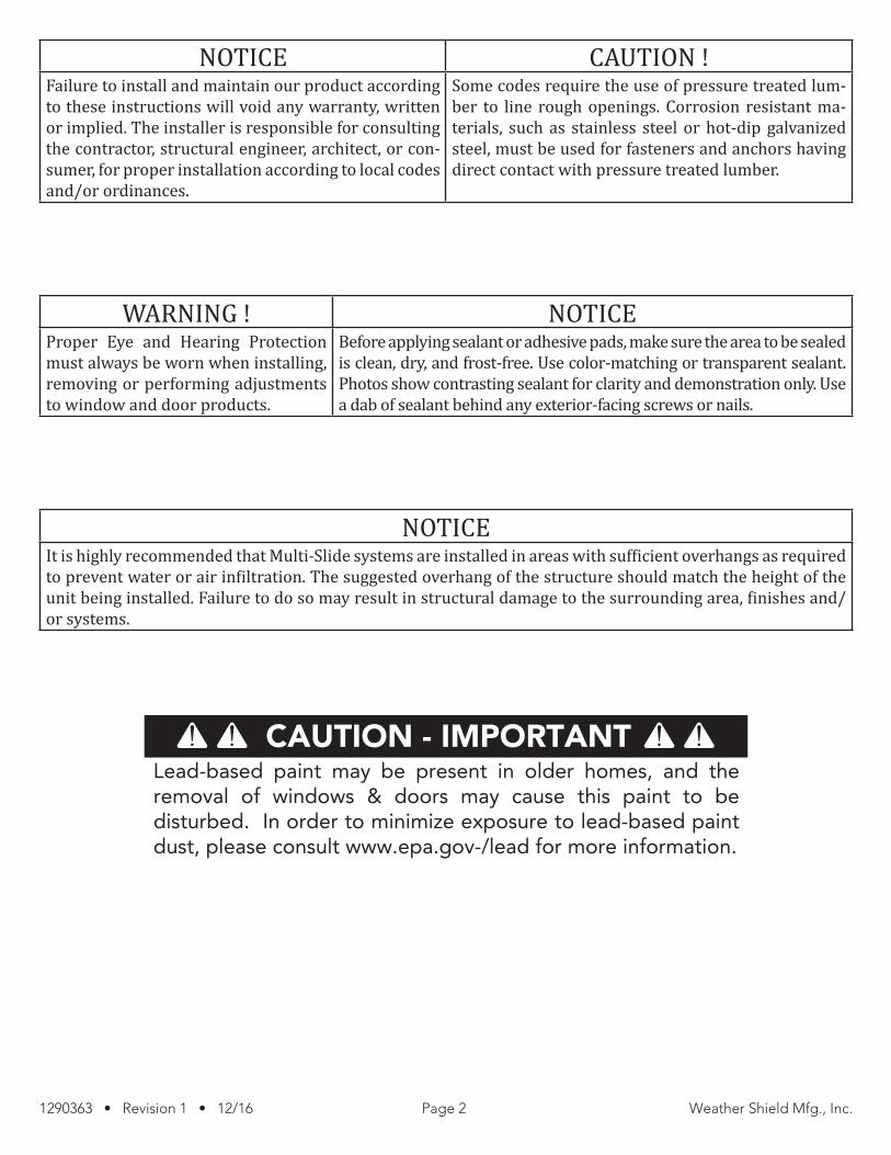
NOTICE CAUTION !Failure to install and maintain our product according to these instructions will void any warranty, written or implied. The installer is responsible for consulting the contractor, structural engineer, architect, or con-sumer, for proper installation according to local codes and/or ordinances.
Some codes require the use of pressure treated lum-ber to line rough openings. Corrosion resistant ma-terials, such as stainless steel or hot-dip galvanized steel, must be used for fasteners and anchors having direct contact with pressure treated lumber.
WARNING ! NOTICE Proper Eye and Hearing Protection must always be worn when installing, removing or performing adjustments to window and door products.
Before applying sealant or adhesive pads, make sure the area to be sealed is clean, dry, and frost-free. Use color-matching or transparent sealant. Photos show contrasting sealant for clarity and demonstration only. Use a dab of sealant behind any exterior-facing screws or nails.
NOTICEIt is highly recommended that Multi-Slide systems are installed in areas with sufficient overhangs as required to prevent water or air infiltration. The suggested overhang of the structure should match the height of the unit being installed. Failure to do so may result in structural damage to the surrounding area, finishes and/or systems.
CAUTION - IMPORTANTLead-based paint may be present in older homes, and the removal of windows & doors may cause this paint to be disturbed. In order to minimize exposure to lead-based paint dust, please consult www.epa.gov-/lead for more information.
1290363 • Revision 1 • 12/16 Page 3 Weather Shield Mfg., Inc.
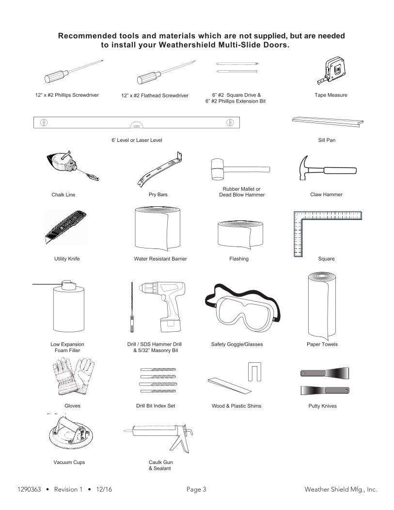
12” x #2 Phillips Screwdriver 6” #2 Square Drive &6” #2 Phillips Extension Bit
Tape Measure
Sill Pan
Caulk Gun & Sealant
Vacuum Cups
Wood & Plastic ShimsGloves
Flashing Square
Drill / SDS Hammer Drill& 5/32” Masonry Bit
Drill Bit Index Set
Low ExpansionFoam Filler
Utility Knife
Safety Goggle/Glasses Paper Towels
Water Resistant Barrier
Dead Blow HammerRubber Mallet or
Claw HammerPry BarsChalk Line
12” x #2 Flathead Screwdriver
Recommended tools and materials which are not supplied, but are neededto install your Weathershield Multi-Slide Doors.
6’ Level or Laser Level
Putty Knives

1290363 • Revision 1 • 12/16 Page 4 Weather Shield Mfg., Inc.
ITEMS PROVIDED BY WEATHER SHIELD • Frame - Head, Side Jambs and sill (to be field assembled)• Stationary Panel(s) (labeled per operating code — quantity based on door configuration)• Active Panels (labeled per operating code — quantity based on door configuration) • “Frame Assembly” screw package • “Sill Install” screw package — Tapcon screws supplied • “Head Jamb Install” screw package • “Astragal” screw package (If needed)• Head Track Caps (quantity based on door configuration)• Side Jamb Track Caps (quantity based on door configuration)Foam corner seals for nail fin • Handle set • Strike — shipped loose or temporarily attached w/slotted holes only (permanently applied after installation & wheel
adjustment) • Panel adjustment caps (quantity based on door configuration) used on holes for roller adjustments and hole for se-
curing stationary panel to frame• Panel collector plates (quantity based on door configuration)• Astragal (Bi-parting units or 90° units only) • 90° corner unit instruction sheet (supplemental sheet if needed)
UNIT PREPARATIONBefore installing your Weather Shield Multi-Sliding Door System, unpack all components; check each against the packing slip and place back into packaging near the appropriate opening until ready to install. If there is any damage or missing parts, please let your distributor know immediately. It is highly recommended that Multi-Slide systems are installed in areas with sufficient overhangs as required to prevent water infiltration. Failure to do so may result structural damage to surrounding area, finishes and/or systems.
OPENING INSPECTIONRough Opening requires a Flat, Level, Straight, Plumb and Square openings. Sill and head jamb must be flat, level, straight, Side jambs must be Plumb, Straight and Square.
VERIFY HEADER SUPPORTConfirm that the roof over the door system is loaded and take into consid-eration that the amount of weight of any materials at this location may cause deflection of the header. No more than 1/8” deflection is allowable for proper system operation.
Verify that the concrete or sub-floor where the system is to be in-stalled is level. The frame system may be shimmed to compensate for an uneven floor but will adjust the relationship of the systems sill to the finished floor and may increase the overall height of the system in the opening. Any serious deflection in the concrete or sub floor must be corrected prior to installation.
Assure that all opening measurements match those noted on the order.
WARNING !Sill sagging and/or humping will affect unit
operation.
Fig. 1 Fig. 2 Fig. 3
Confirm Floor is Level See Shimming Note Above
1290363 • Revision 1 • 12/16 Page 5 Weather Shield Mfg., Inc.
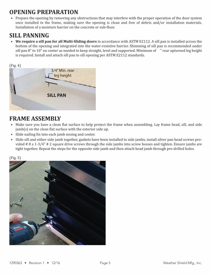
OPENING PREPARATION• Prepare the opening by removing any obstructions that may interfere with the proper operation of the door system
once installed in the frame, making sure the opening is clean and free of debris and/or installation materials. Installation of a moisture barrier on the concrete or sub-floor.
SILL PANNING• We require a sill pan for all Multi-Sliding doors in accordance with ASTM E2112. A sill pan is installed across the
bottom of the opening and integrated into the water-resistive barrier. Shimming of sill pan is recommended under sill pan 8” to 10” on center as needed to keep straight, level and supported. Minimum of ¾” rear upturned leg height is required. Install and attach sill pan to sill opening per ASTM E2112 standards.
(Fig. 4)
FRAME ASSEMBLY • Make sure you have a clean flat surface to help protect the frame when assembling. Lay frame head, sill, and side
jamb(s) on the clean flat surface with the exterior side up. • Slide nailing fin into each jamb nosing and center. • Slide sill and either side jamb together, gaskets have been installed to side jambs, install silver pan head screws pro-
vided # 8 x 1-3/4” # 2 square drive screws through the side jambs into screw bosses and tighten. Ensure jambs are tight together. Repeat the steps for the opposite side jamb and then attach head jamb through pre-drilled holes.
(Fig. 5)
SILL PAN
3/4” Min. rearleg height

1290363 • Revision 1 • 12/16 Page 6 Weather Shield Mfg., Inc.
FRAME INSTALLATION• Apply a continuous 3/16” bead of sealant to the backside of the nailing fin and frame joint. This seals the area of the
frame. Apply head/side jamb corner pads on top corners. Apply a continuous bead of sealant to the back side of the nailing fin ½” in from edge of nailing fin.
(Fig. 6a & 6b)
• Install frame into rough opening. Apply 3/16” bead of sealant along the interior upturned leg of the sill pan. Check the sill for straightness along its entire length. Pull or push straight before drilling and anchoring to the floor.
• When installing on wood sub-floor install, apply sealant into sill screw holes location then install screw to sill track, apply sealant over screw head and tool smooth.
• When installing on a concrete floor pre-drill the holes using 5/32” masonry bit. The hole should be 2-1/4” deep into concrete floor to accept screws included in the screw package. Vacuum or blow dust from hole, apply sealant into the hole, then install 1-3/4” masonry screw. Apply sealant over screw head and tool sealant until it is level and flat. Use shims as needed to flatten the sill. Apply sealant in each pre-drilled hole in the sill.
(Fig. 7)
Apply 3/16” bead of sealant
Apply 3/16” bead of sealant

1290363 • Revision 1 • 12/16 Page 7 Weather Shield Mfg., Inc.
• Prior to attaching the head to rough opening, square the door frame to within 1/8” – 3/16” tolerance. Use a tape measure to measure diagonally from corner to corner. Use a straight edge and or level, verify that the top track/head is level and flat (1/8” maximum). Use shims as needed to level and straighten the head. Attach the head through the pre-drilled holes in frame use black # 2 square drive screws provided in the screw package.
(Fig. 8)
• Use a straight edge and or level, verify that the side jambs are level and straight (1/8” maximum). Use shims as needed to level and straighten the side jambs. Attach the side jambs through the pre-drilled holes in frame use the black # 2 square drive screws provided in the screw package. NOTE: Fasten the exterior nailing fins to the framing using fasteners that penetrate material by at least 1-1/2”.
(Fig. 9)

1290363 • Revision 1 • 12/16 Page 8 Weather Shield Mfg., Inc.
• Cross measure the frame to confirm there is no variance larger than 1/8”- 3/16” difference diagonally frame for square, head and sides within 1/8”- 3/16” diagonally horizontally and vertically.
(Fig. 10 & 11)
FLASHING METHODTape Application – Side Pieces• Start at the top above the door. Apply tape to the face of the wall close to the frame and work toward the bottom. Tape
must cover the entire nailing fin, including the installation holes, the joint between the fin and the building’s sheath-ing and extend out onto the exterior wall. Use a rubber roller to get good contact between the tape and the wall. Tape ends 1/2” above sill tape.
(Fig. 12 & 13)
Head Piece Application• Apply top piece of self-adhering water barrier tape so one end extends 1” beyond a side piece of tape. Apply top piece
across the head jamb and over the opposite side piece of tape. Both ends of top piece should overlap side pieces by 1”. Use a rubber roller to get good contact with the wall surface.
• Apply sealant along full width of self-adhering water barrier tape from side to side.
WIDTH
HEIGHT
APPLY SEALANT IN ALL LOCATIO
NS
1" OVERLAPEACH SIDE
1290363 • Revision 1 • 12/16 Page 9 Weather Shield Mfg., Inc.
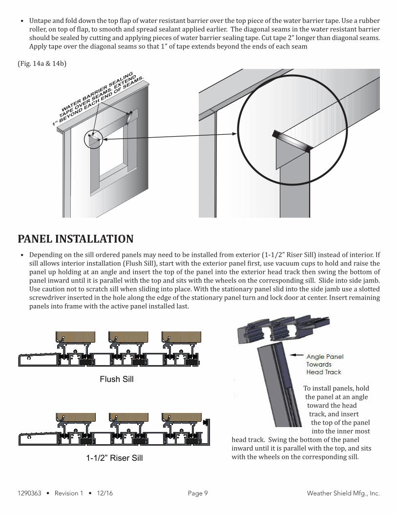
• Untape and fold down the top flap of water resistant barrier over the top piece of the water barrier tape. Use a rubber roller, on top of flap, to smooth and spread sealant applied earlier. The diagonal seams in the water resistant barrier should be sealed by cutting and applying pieces of water barrier sealing tape. Cut tape 2” longer than diagonal seams. Apply tape over the diagonal seams so that 1” of tape extends beyond the ends of each seam
(Fig. 14a & 14b)
PANEL INSTALLATION• Depending on the sill ordered panels may need to be installed from exterior (1-1/2” Riser Sill) instead of interior. If
sill allows interior installation (Flush Sill), start with the exterior panel first, use vacuum cups to hold and raise the panel up holding at an angle and insert the top of the panel into the exterior head track then swing the bottom of panel inward until it is parallel with the top and sits with the wheels on the corresponding sill. Slide into side jamb. Use caution not to scratch sill when sliding into place. With the stationary panel slid into the side jamb use a slotted screwdriver inserted in the hole along the edge of the stationary panel turn and lock door at center. Insert remaining panels into frame with the active panel installed last.
WATER BARRIER SEALING
TAPE OVER SEAMS. E
XTEND
1" BEYOND EACH END OF SEAMS.
Flush Sill
1-1/2” Riser Sill
To install panels, hold the panel at an angle toward the head track, and insert the top of the panel into the inner most
head track. Swing the bottom of the panel inward until it is parallel with the top, and sits with the wheels on the corresponding sill.

1290363 • Revision 1 • 12/16 Page 10 Weather Shield Mfg., Inc.
PANEL LAYOUT• Depending on the code of the door (panels will be labeled accordingly to ensure they are installed in the correct lo-
cation in each door frame. Below is an example of an 8-panel bi-parting door with 4 panels stacking on the left and 4 on the right. A sheet will be included with the installation hardware that depicts your exact door configuration, please refer to it prior to installing your door panels.
A label similar to this will appear on the glass of each door panel:
(Fig. 15)
ADJUSTMENTS• After all panels are installed close the panels and adjust the rollers to align the door stiles and rail heights. The 2
adjustment holes are located at the bottom of each panel. Use a large screwdriver to adjust panel. While adjusting, lift the panel slightly to remove weight from the roller, then raise or lower the wheels as required to have the panels aligned. After adjustments the adjustment plugs can be installed. Panels can use the plastic adjustment plugs or the wood plug with adhesive.
(Fig. 16)

1290363 • Revision 1 • 12/16 Page 11 Weather Shield Mfg., Inc.
HEAD AND SIDE JAMB FILLER• Install head and side jamb aluminum fillers into exterior frame. Check the lengths if needed trim to fit. To install
position the filler into the frame cavity lay a block of wood against filler and pound filler in place using a dead blow hammer. Wood fillers snap into the vinyl clips position the clips near each end and center the remaining clips. The wood is then pushed onto frame and snapped into the clip.
(Fig. 17 & 18)
• Active door strike plate screws: Remove the top and bottom strike plates screws and replace # 8 x 2-3/8” flat head screws
(Fig. 19)
Head Cavity Cover