Embed Size (px)
Citation preview

MSRA145Nominal Capacity 73 to 1473 kW(R)
Issue: 4.0 Date 10/12
MSRA SERIESModular Air Cooled Scroll Heat Pump Chiller

CONTENTS
Features 1
MV6 Control 4 Physical Data 6
Unit Capacity 10
Chiller Selection 12
Electrical Data 13
Wiring Diagram 15
Physical Dimension 17
Piping Schematic 19

STRUCTUREMULTISTACK Air Cooled Chillers are designed and constructed under the modular technol-
ogy patent. A chiller bank consists of multiple individual chiller modules connected in par-
allel to operate as a single machine, with cooling or heating capacity to match the load
demand by varying the number of operating modules. The chiller modules start from a small
half module, and expandable to ten full modules for MSRA145, giving you full flexibility to
increase the capacity as your needs increase.
Each full module consists of two scroll compressors, evaporator, condenser, and sophisticat-
ed control and protection equipment. Each module operates as a completely independent
refrigeration circuit, and varying to the total load demand. The controller changes the
chiller’s capacity by either controlling the number of modules in operation or by adjusting
the capacity of the last start up compressor.
The Multistack Air Cooled line-up is available in cooling-only version or heat pump version for dual operation.
COMPACT AND SPACE-SAVINGThe compact size of each module means easy access via standard doorways and lifts. You no longer need
special access to install the chiller.
LOWER INSTALLATION COSTConnection of the modules has never been simpler – only two pipes
to connect followed by the communication cables and you’re in
business. ADD-ON FLEXIBILITYEach module in the Multistack system delivers both, cooling and heat-
ing. As many as 10 full modules can be connected together as a chiller
bank. Multistack chillers has inbuilt flexibility which is useful in tenancy
changes and strata title applications.
Features
1

“GIVING Y OU OUTSTANDING RELIABILITY & PERFORMANCE”
SAFE AND RELIABLEEvery module works as an independent refrigeration circuit, with adjacent modules operating independently. In the
event of a malfunction in the system, the computer selects the next available standby module to provide back up. One
failed module will not disrupt the other chillers or system, giving you total peace of mind.
PEAK ECONOMY AT ALL LOADSAutomatic scheduling of the compressors allows the chiller to match the fluctuating cooling/heating loads and con-
serve energy with each individual unit running at its peak efficiency. This is much more economical when compared
to a large single unit running at part load.
UNPARALLELED RELIABILITYEvery Multistack slave module is identical to each other, so in the event of a malfunction in the system, the computer
automatically selects the next available standby circuit to provide back up. For critical air conditioning and industrial
process cooling a Multistack modular chiller inherently provides economical standby capacity and unparalleled de-
pendability.
HIGH EFFICIENCY, QUIET OPERATING SCROLL COMPRESSOROur compressors have a high coefficient of performance (COP) – (approximately 9% higher than that of a reciprocat-
ing compressor)- and an outstanding reliability due to fewer moving parts, lower starting toque, and tolerance for
flood-back and a rigid internal construction. All this is achieved through high volumetric efficiency, minimized pressure
losses due to the absence of valve plates, and reduced heat transfer loss due to better separation of suction and dis-
charge gases. In addition, scroll compressors produce less vibrations and are quieter than that of their hermetic counter-
parts (due to absence of dynamic suction and discharge valves and a much smoother compression process).

Other Heat Pump Chiller
Multistack Heat Pump Chiller
EXCLUSIVE DEFROSTING TECHNOLOGYThe chiller not only adapts to the heat pump cycle (which is specifically designed to improve heat pump operational
performance and obtaining a faster defrosting cycle), but also when an even amount of frost build-up is present; it will
thaw it completely in a very short time. Defrosting cycle is only carried out when the demand for defrosting is present
in each module, which means the modules that are frosted will defrost, while the others remain in operation, giving
you a reliable and fully uninterrupted system.
This exclusive defrosting technology can ensure complete defrosting even in the harshest of environments, ensuring
you with excellent heating performance, and a comfortable environment all year round.
ENVIRONMENTALLY FRIENDLYMultistack Chillers are friendly to the environment and currently running on the non-toxic R22 refrigerant (approved
under the Montral Protocol, and for sale until 2030) as standard, along with the R407c and R134a as optional. It is also
pleasing to the ears, running quietly even at 100% capacity.
3

The MV6 computer control monitors the chiller’s operation and schedules the on and off of each compressor
and capacity control stages with respect to the change in load demand. The computer continuously and compre-
hensively monitors the total operation of all modules in the chiller bank. It will also shut down individual module
or the entire bank in the event that a fault occurs. A maximum of 32 refrigeration circuits can be monitored at
one time.
COMPRESSOR SEQUENCEThe MV6 controller accumulates the running hours of each compressor and hence establishes working se-
quence. A standby compressor with the least working hours will be activated during loading. The same goes for
a compressor with the most working hours will be stopped during unloading. This ensures each compressor in
the system has an even usage, which will save you time and money in the long run for maintenance.
FAULT REVIEWThe controller will record and display the last 60 faults that occurred, giving detailed information such as time,
date, location, cause, current status, as well as the performance data collected at the moment each fault oc-
curred.
MV6 Control
System data and Variables DisplayThe controller’s 5.7” touch panel not only can display the
chiller’s operation data but also provides you with direct
access to all of the chillers setting and variables for total
system control.
Chiller operation status
___chilled water temperature
___condenser water temperature
___% of chiller cooling capacity
___% demand loading
___load / unload time delay
___current fault number
___% of loading limitation
___lead compressor
Module operation status
___compressor suction pressure
___compressor discharge pressure
___evaporating temperature
___chilled water leaving temperature
___faults status
Chiller variables settings
___password
___chilled water temperature
___lead compressor
___temperature integrating time
___economy offset
___load / unload time delay
___time and date

LOAD PROFILEThe controller records all working hours of the chiller and compressor and records it accordingly in 10%
brackets from 0% - 100%, giving you detailed information for which percentage the chiller is running mostly.
PASSWORDA two level password protection is included (for both customer and service personnel) to give you peace of
mind. For example the service password will give you full access to settings and variables, but the user pass-
word will only enable the user see but not change settings and variables.
STANDBY CONTROLEach module can be set for three modes: auto/ off/ independent operation via the slave outstation
card installed in the module. Default setting is “auto”, with “off” mode for when maintenance is re-
quired and “independent” mode (where the module is controlled by its own slave outstation card and
operates independently from the controller), is usually for commissioning or emergency operation.
REMOTE CONTROL & MONITORING (OPTIONAL)MV6 is fitted with a RS485 serial port which enables remote control monitoring.
(1) Connect it to a pc and install the software (Ms Windows based only) and away you go. Multistack’s
RCM software give you full access to the chillers controls and settings, with a maximum communi-
cation cable length of 1200m.
(2) The MV6 is open to the ASCII agreement and communicates with BAS.
(3) Connect it to an Ethernet-card and with an IP address you can access the chiller over the internet
giving you absolute flexibility.
M SR A 5 A B F
1 2 3 5 6 8 9
MODEL NUMBER DESIGNATION
1 Modular Series
2 Scroll Chiller
3 Cooling Type
A:Air Cooled
W:Water Cooled
4 Model Type
MSRA145
5 Chiller Type
C: Cooling Only
H: Heat Pump
6 The number of modules
MSRA145: 0.5-10.0
7 Electrical Specifications
A: 380-415V, 50Hz, 3 Phase
B: 380V, 60Hz, 3 Phase
C: 440-480V, 60Hz, 3 Phase
8 Configuration
B: Back to Back (Standard)
E: End to End (Option) *For MSRA145 only
9 Refrigerant
E:R134a
F:R22
R:R407c
10 Water System
V: VWF
Blank for standard
5
145A
3 4 5 6 7 8 9 10
C - 6.0 A B F VSRM
1 2
6
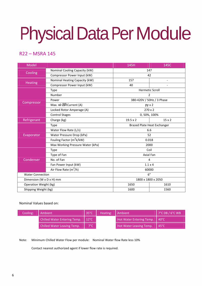
Physical Data Per Module
R22 – MSRA 145
Model 145H 145C
Cooling Nominal Cooling Capacity (kW) 147 Compressor Power Input (kW) 42
Heating Nominal Heating Capacity (kW) 157 - Compressor Power Input (kW) 40 -
Compressor
Type Hermetic Scroll Number 2 Power 380-420V / 50Hz / 3 Phase Max. wŀǘŜŘ Current (A) ру x 2 Locked Rotor Amperage (A) 270 x 2 Control Stages 0, 50%, 100%
Refrigerant Charge (kg) 19.5 x 2 15 x 2
Evaporator
Type Brazed Plate Heat Exchanger Water Flow Rate (L/s) 6.6 Water Pressure Drop (kPa) 52 Fouling Factor (m2k/kW) 0.018 Max Working Pressure Water (kPa) 2000
Condenser
Type Coil Type of Fan Axial Fan No. of Fan 4 Fan Power Input (kW) 1.1 x 4 Air Flow Rate (m3/h) 60000
Water Connection 6” Dimension (W x D x H) mm 1800 x 1800 x 2050 Operation Weight (kg) 1650 1610 Shipping Weight (kg) 1600 1560
Nominal Values based on:
Cooling: Ambient 35°C Heating: Ambient 7°C DB / 6°C WB
Chilled Water Entering Temp. 12°C Hot Water Entering Temp. 40°C
Chilled Water Leaving Temp. 7°C Hot Water Leaving Temp. 45°C
Note: Minimum Chilled Water Flow per module: Nominal Water flow Rate less 10%
Contact nearest authorized agent if lower flow rate is required.

7
R407C – MSRA 145
Model 145H 145C
Cooling Nominal Cooling Capacity (kW) 135 Compressor Power Input (kW) 41
Heating Nominal Heating Capacity (kW) 147 - Compressor Power Input (kW) 40 -
Compressor
Type Hermetic Scroll Number 2 Power 380-420V / 50Hz / 3 Phase Max. wŀǘŜŘ Current (A) ру x 2 Locked Rotor Amperage (A) 270 x 2 Control Stages 0, 50%, 100%
Refrigerant Charge (kg) 17.8 x 2 13.5 x 2
Evaporator
Type Brazed Plate Heat Exchanger Water Flow Rate (L/s) 6.п Water Pressure Drop (kPa) 52 Fouling Factor (m2k/kW) 0.018 Max Working Pressure Water (kPa) 2000
Condenser
Type Coil Type of Fan Axial Fan No. of Fan 4 Fan Power Input (kW) 1.1 x 4 Air Flow Rate (m3/h) 60000
Water Connection 6” Dimension (W x D x H) mm 1800 x 1800 x 2050 Operation Weight (kg) 1650 1610 Shipping Weight (kg) 1600 1560
Nominal Values based on:
Cooling: Ambient 35°C Heating: Ambient 7°C DB / 6°C WB
Chilled Water Entering Temp. 12°C Hot Water Entering Temp. 40°C
Chilled Water Leaving Temp. 7°C Hot Water Leaving Temp. 45°C
Note: Minimum Chilled Water Flow per module: Nominal Water flow Rate less 10%
Contact nearest authorized agent if lower flow rate is required.

8
R134A – MSRA 145
Model 145H 145C
Cooling Nominal Cooling Capacity (kW) 92 Compressor Power Input (kW) 29
Heating Nominal Heating Capacity (kW) 99 - Compressor Power Input (kW) 28 -
Compressor
Type Hermetic Scroll Number 2 Power 380-420V / 50Hz / 3 Phase Max. wŀǘŜŘ Current (A) ру x 2 Locked Rotor Amperage (A) 270 x 2 Control Stages 0, 50%, 100%
Refrigerant Charge (kg) 18.5 x 2 14.2 x 2
Evaporator
Type Brazed Plate Heat Exchanger Water Flow Rate (L/s) пΦп Water Pressure Drop (kPa) 52 Fouling Factor (m2k/kW) 0.018 Max Working Pressure Water (kPa) 2000
Condenser
Type Coil Type of Fan Axial Fan No. of Fan 4 Fan Power Input (kW) 1.1 x 4 Air Flow Rate (m3/h) 60000
Water Connection 6” Dimension (W x D x H) mm 1800 x 1800 x 2050 Operation Weight (kg) 1650 1610 Shipping Weight (kg) 1600 1560
Nominal Values based on:
Cooling: Ambient 35°C Heating: Ambient 7°C DB / 6°C WB
Chilled Water Entering Temp. 12°C Hot Water Entering Temp. 40°C
Chilled Water Leaving Temp. 7°C Hot Water Leaving Temp. 45°C
Note: Minimum Chilled Water Flow per module: Nominal Water flow Rate less 10%
Contact nearest authorized agent if lower flow rate is required.

Heat Exchanger Water Pressure Drop
Pressure drop correction factor: k related to the modules’ number: n of the chiller bank
N 0.5 - 3.0 3.5 - 4.0 4.5 5.0 5.5 6.0 6.5 7.0 7.5 8.0 8.5 9.0 9.5 10.5
MSRA145 1.00 1.01 1.02 1.02 1.03 1.03 1.04 1.05 1.06 1.07 1.08 1.09 1.11 1.11
9
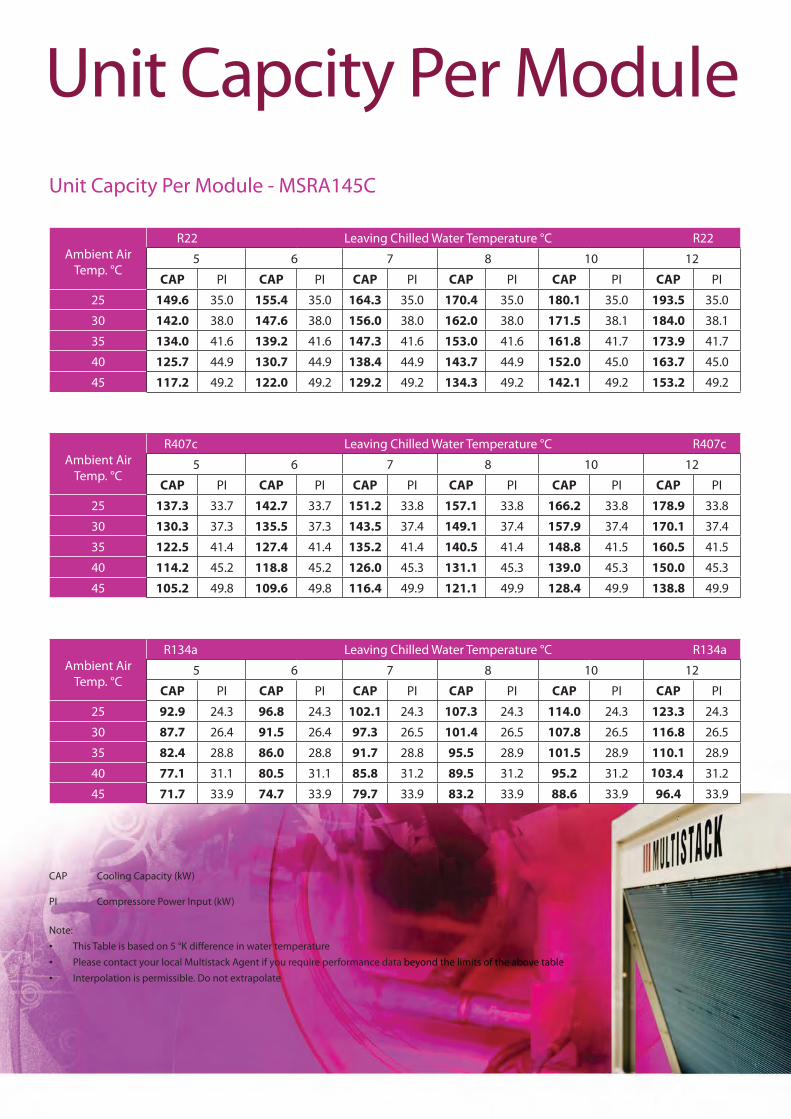
Ambient Air
Temp. °C
R22 Leaving Chilled Water Temperature °C R22
5 6 7 8 10 12
CAP PI CAP PI CAP PI CAP PI CAP PI CAP PI
25 149.6 35.0 155.4 35.0 164.3 35.0 170.4 35.0 180.1 35.0 193.5 35.0
30 142.0 38.0 147.6 38.0 156.0 38.0 162.0 38.0 171.5 38.1 184.0 38.1
35 134.0 41.6 139.2 41.6 147.3 41.6 153.0 41.6 161.8 41.7 173.9 41.7
40 125.7 44.9 130.7 44.9 138.4 44.9 143.7 44.9 152.0 45.0 163.7 45.0
45 117.2 49.2 122.0 49.2 129.2 49.2 134.3 49.2 142.1 49.2 153.2 49.2
Unit Capcity Per ModuleUnit Capcity Per Module - MSRA145C
CAP Cooling Capacity (kW)
PI Compressore Power Input (kW)
Note:
Please contact your local Multistack Agent if you require performance data beyond the limits of the above tableInterpolation is permissible. Do not extrapolate
Ambient Air
Temp. °C
R407c Leaving Chilled Water Temperature °C R407c
5 6 7 8 10 12
CAP PI CAP PI CAP PI CAP PI CAP PI CAP PI
25 137.3 33.7 142.7 33.7 151.2 33.8 157.1 33.8 166.2 33.8 178.9 33.8
30 130.3 37.3 135.5 37.3 143.5 37.4 149.1 37.4 157.9 37.4 170.1 37.4
35 122.5 41.4 127.4 41.4 135.2 41.4 140.5 41.4 148.8 41.5 160.5 41.5
40 114.2 45.2 118.8 45.2 126.0 45.3 131.1 45.3 139.0 45.3 150.0 45.3
45 105.2 49.8 109.6 49.8 116.4 49.9 121.1 49.9 128.4 49.9 138.8 49.9
Ambient Air
Temp. °C
R134a Leaving Chilled Water Temperature °C R134a
5 6 7 8 10 12
CAP PI CAP PI CAP PI CAP PI CAP PI CAP PI
25 92.9 24.3 96.8 24.3 102.1 24.3 107.3 24.3 114.0 24.3 123.3 24.3
30 87.7 26.4 91.5 26.4 97.3 26.5 101.4 26.5 107.8 26.5 116.8 26.5
35 82.4 28.8 86.0 28.8 91.7 28.8 95.5 28.9 101.5 28.9 110.1 28.9
40 77.1 31.1 80.5 31.1 85.8 31.2 89.5 31.2 95.2 31.2 103.4 31.2
45 71.7 33.9 74.7 33.9 79.7 33.9 83.2 33.9 88.6 33.9 96.4 33.9

Ambient Air
Temp. °C
R22 Leaving Hot Water Temperature °C R22
CAPH PI CAPH PI CAPH PI CAPH PI CAPH PI
15 186.5 34.8 182.0 37.8 177.3 40.5 173.0 44.7 169.0 48.9
10 169.4 34.8 165.6 37.8 161.8 40.5 158.3 44.7 155.2 48.9
7 164.0 34.8 160.5 37.8 156.9 40.4 153.6 44.6 150.7 48.9
5 158.8 34.8 155.5 37.8 152.1 40.4 149.1 44.6
0 139.4 34.7 137.0 37.7 134.6 40.4
-5 122.4 34.7 120.7 37.7
Unit Capcity Per Module - MSRA145H
CAPH Heating Capacity (kW)
PI Compressore Power Input (kW)
Note:
Please contact your local Multistack Agent if you require performance data beyond the limits of the above tableInterpolation is permissible. Do not extrapolate
Ambient Air
Temp. °C
R407c Leaving Hot Water Temperature °C R407c
CAPH PI CAPH PI CAPH PI CAPH PI CAPH PI
15 174.2 33.6 170.6 37.2 166.4 40.5 162.1 45.0 157.6 49.6
10 157.8 33.6 154.9 37.2 151.5 40.5 148.0 45.0 144.4 49.6
7 152.7 33.6 150.0 37.1 146.8 40.4 143.5 45.0 140.1 49.6
5 147.8 33.6 145.2 37.1 142.3 40.4 139.2 45.0
0 129.4 33.5 127.5 37.1 125.4 40.4
-5 113.2 33.5
Ambient Air
Temp. °C
R134a Leaving Hot Water Temperature °C R134a
CAPH PI CAPH PI CAPH PI CAPH PI CAPH PI
15 118.4 24.2 115.6 26.4 112.9 28.4 110.3 31.1 107.9 33.8
10 107.0 24.2 104.6 26.4 102.4 28.4 100.4 31.1 98.5 33.8
7 103.4 24.2 101.2 26.3 99.1 28.3 97.2 31.0 95.6 33.8
5 99.9 24.2 97.9 26.3 95.9 28.3 94.2 31.0 92.8 33.8
0 87.1 24.2 85.6 26.3 84.4 28.3 83.2 31.0
-5 76.0 24.2 74.9 26.3 74.1 28.3
11
35 40 45 50 55
35 40 45 50 55
35 40 45 50 55

Chiller SelectionSelect air-cooled chiller according to following conditions:
��� Entering Chilled Water Temperature (ECHW)............................................................ 12.5 °C
��� Leaving Chilled water Temperature (LCHW).............................................................. 7 °C
��� Chiller Water Flow (CHWF)................................................................................................ 24.6 l/s
��� Ambient Temperature........................................................................................................ 35.0 °C
�� Leaving Hot Water Temperature..................................................................................... 45.0 °C
�� Entering Hot Water Temperature.................................................................................... 40.0 °C
��� Hot Water Flow Rate............................................................................................................ 24.4 l/s
��� Ambient Temperature (AT)............................................................................................... 0.0 °C
�� Refigerant............................................................................................................................... R22
���� Power........................................................................................................................................ AC380V ±10%/50Hz/3phz
Calculation
1. Determine cooling capacity required (kW)Cooling Capacity = CHWF × Water Specific Heat ×(ECHW - LCHW) = 24.6 × 4.187 ×( 12-7) = 515kW required
Heating Capacity = HWF × 4.187 ×(HWLT - HWET) = 22.4 × 4.187 ×(45.0 – 40.0) = 469kW required
2. From capacity chart above,- 1 module at stated conditions will achieve;Cooling CAP= 147 kW per MSRA145 module Heating CAP= 135 kW per MSRA145 module
Divide the required capacity by achieved capacity at specified conditions to determine required number of modules:
= 515kW required ÷ 147kW achieved = 3.5 modules
Select 4 modules of MSRA145HCooling Capacity of 4 modules = 4 x 147 = 588kW Heating Capacity of 4 modules = 4 x 135 = 540kW
3. To establish Water Flow per module, divide new CHWF by number of modules:(1) Nominal Water flow = 4 x 6.6 = 26.4 l/s Chilled Water Pressure Drop for nominal water flow per module is 52kPa (2) Actual water pressure drop 24.6 ÷ 26.4 = 93.2% Use the chart “Pressure Drop Correction Factor for chilled and condenser water Circuit”, 4 modules of MSRA145 the correction ξ is 0.87 for 93.2% of water flow.
Use the table « Pressure drop correction factor: k », k=1.01 for the configuration: 4 modules of MSRA145H
Actual condenser water pressure drop is:52 x 0.87 x 1.01 = 45.7kPa
(Contact Multistack if lower flow rate is required.)
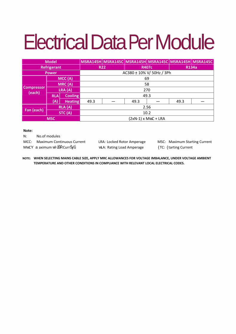
ElectricalDataPerModule
Note: N: No.of modules MCC: Maximum Continuous Current LRA: Locked Rotor Amperage MSC: Maximum Starting Current MwCΥ aaximum wŀǘŜŘ CurrŜƴǘ wLA: Rating Load Amperage {TC: {tarting Current
NOTE: WHEN SELECTING MAINS CABLE SIZE, APPLY MRC ALLOWANCES FOR VOLTAGE IMBALANCE, UNDER VOLTAGE AMBIENT TEMPERATURE AND OTHER CONDITIONS IN COMPLIANCE WITH RELEVANT LOCAL ELECTRICAL CODES.
Model MSRA145H MSRA145C MSRA145H MSRA145C MSRA145H MSRA145C Refrigerant R22 R407c R134a
Power AC380 ± 10% V/ 50Hz / 3Ph
Compressor (each)
MCC (A) 69 MRC (A) 58 LRA (A) 270
RLA (A)
Cooling 49.3 Heating 49.3 — 49.3 — 49.3 —
Fan (each) RLA (A) 2.56 STC (A) 10.2
MSC (2xN-1) x MwC + LRA

MSRA145 TERMINATION CONNECTION
No. of ModulesMains Termination
Location Connection Procedure
0.5 – 1.0 Half Module Electrical Cubicle Connect with main circuit breaker of each half module respectively1.5 – 10.0 Electrical Cubicle
N=0.5-1.0
N=1.5-5.0 N=5.5-10.0
Notes:
Supply 380v – 415V, 50Hz / 3 phase
1. Design running current is the steady state current draw at a particular set of conditions, ie ambient and chilled water temperatures.
2. Maximum rated current (MRC) is the maximum expected current draw at transient (pull down) and/or greater than design conditions.
Cable Sizing
When selecting mains cable size use MRC. Allowances must be made for voltage imbalance, ambient temperature and other conditions in compliance with AS 3000 or local relevant electrical codes.
Mains Termination
The termination for a full module is at a terminal block located in the back half module electrical housing. For a half only module, termination is at the fuse holders or circuit breaker located in the electrical housing.
( To be supplied by customer )
Electrical Box and related wiring (prepared by user)
Elec
tric
al B
ox
AC380V50Hz3Ph
MULTISTACK MULTISTACK MULTISTACK MULTISTACK MULTISTACK MULTISTACK

Field Wiring Diagram
CHWF Chilled water flow switchEXT1 External interlock device (Manual reset)EXT2 External interlock device (Austo reset)R Running StatusCWP Condensor water pump running statusCAR Customer fault alarm relayCPR Compressor running statusCE Communication error
Notes:- Control wiring to be 18AWG or 1.0sqmm minimum.- Bridge between terminals T3 & T5 is EXT-1 is not utilised.- Bridge between terminals T4 & T% if EXT-2 is not utilised.- Free contacts have a maximum rating of 5 Amps.- Flow switches and external interlock devices are not supplied by Multistack- Wiring by Multistack _______ / Wiring by others ----------
15

FIELD WIRING DIAGRAM CONT.

Physical Dimensions Configuration: Back to Back (Standard)
Note:
1. All installations must have: - 3/8” BSP sockets in all water connections adjacent to chiller for Multistack sensor installation. - Φ60 mesh stainless steel strainers in chilled water inlet piping.
2. Only one computer is to be installed per chiller bank. 3. Chilled water connections can be at either or both ends of chiller. (optional) 4. Single module installation mains termination is at terminal strip located in the compressor electrical box. 5. Chiller may be mounted on 4 x100 sq. RHS positioned as shown (RHS not supplied by manufacturer). 6. Operating weight: 1600kg per full module.

Configuration: End to End (Optional)
Note:
1. All installations must have: - 3/8” BSP sockets in all water connections adjacent to chiller for Multistack sensor installation. - Φ60mesh stainless steel strainers in chilled water inlet piping.
2. If chiller is to be expanded to back to back configuration. A minimum of 3000mm rear clearance is required. 3. Only one computer is to be installed per chiller bank. 4. Chilled water connections can be at either or both ends of chiller. (optional) 5. Single module installation mains termination is at terminal strip located in the compressor electrical box. 6. Chiller may be mounted on 4 x100 sq. RHS positioned as shown (RHS not supplied by manufacturer). 7. Operating weight: 800kg per full module.

Piping Schematic
Item Description Qty
1 Drain Valve DN50 2
2 Temperature Sensor Socket 3/8” 2
3 Vibration Eliminator 2
4 Pressure Guage 2
8 Isolation Gate Valve 4
Item Description Qty
6 Bypass Valve 1
7 Flow Switch 1
8 Water Pump
9 Strainer 25 Mesh/Inch 1
10 Pressure Differential Bypass Valve 1
19

Since MULTISTACK INTERNATIONAL LIMITED has a policy of continuous product improvement, it reserves the right to change design and specification without notice.
Multistack supplied by DunnAir international Limited (a wholly owned subsidiary of Multistack International Limited).
MULTISTACK INTERNATIONAL LIMITED
140 BERNARD STREET, CHELTENHAM, VICTORIA 3192, AUSTRALIA
TELEPHONE: 61 3 8586 8200 FACSIMILE 61 3 8586 8202
Email: [email protected]
Web site: www.multistack.com.au