Embed Size (px)
Citation preview

PRE-FEASIBILITY REPORT For
PRIOR ENVIRONMENTAL CLEARANCE
Environmental Impact Assessment for increasing
production volume through debottlenecking of existing
Machineries and fuel change for SRF Ltd
at
Village-Malanpur, District- Bhind,
Madhya Pradesh
Project Proponent:
M/s. SRF
Environmental Consultant:
Recognized by MoEF (GOI) as per EPA and valid up to Jan’2019
Accredited by NABL for Chemical &Biological), valid up to 03.10.2016
Accredited under the QCI-NABET Scheme for EIA Consultant Certified by ISO 9001:2008, ISO 14001:2004, OHSAS 18001:2007
Head Office: 60, Bajiprabhu Nagar, Nagpur-440 033, MS
Lab. : FP-34, 35, Food Park, MIDC, Butibori, Nagpur – 441122
Ph.: (0712) 2242077, 9373287475 Fax: (0712) 2242077
Email: [email protected], [email protected]
Website: www.anaconlaboratories.com
March 2016

1
INDEX
S. No. Contents Page. No.
1. Introduction
1.1 Company Profile 1
1.2 Need and justification of the project 1
1.3 Market scenario 1
1.4 Land allocation 2
1.5 The Project 2
1.6 Project Proponent 2
1.7 Project Schedule 3
2. Project Descriptions
2.1 Type of Project 4
2.2 Location of Plant site 4
2.3 Selection of Site (Alternate site) 9
2.4 Topography and land use 9
2.5 Project Description 9
3. Infrastructure Facility
3.1 Raw material 13
3.2 Transportation and route connectivity 13
3.3 Amenities / Facilities 13
3.4 Manpower 13
3.5 Greenbelt and plantation 13
3.6 Effluent treatment plant 13
3.7 Solid & Hazardous waste management 14
3.8 Rain water harvesting 14
4. Resource Availability
4.1 Raw materials 14
4.2 Water availability 15
4.3 Power requirement and supply 15
5. Environmental Aspects
5.1 Environmental setting 15
5.2 Water Requirement wastewater generation and treatment 16
5.3 Power requirement 23
5.4 Solid and Hazardous waste generation 23
5.5 Noise Generation 23
5.6 Air emission 24
5.7 Plantation 24
5.8 Waste Disposal (Liquid & Solid) 24
6. Project Schedule and cost Estimates
6.1 Project Schedule 24
6.2 Cost estimates 25
6.3 Economic viability 25
7. Corporate Social responsibility (CSR) Policy

2
Figures
S. No. Figure Name Page. No.
1 Location Map of the Project site 5
2 10 Km Radius map from project site on toposheet 6
3 Existing Layout Plant of SRF 7
4 Google View with Coordinate of the Plant Site 8
5 Process flow diagram 12
6 ETP flow Diagram 18
7 RO system in the treatment plant 19
8 Designing for use of treated wastewater for plantation 20
9 Installation of ozone generation in the treatment system 21
Tables
S. No. Table name Page. No.
1 Land Use Breakup 9
2 Existing Water Balance 17
3 Diffused aeration system for aeration tank 1 technical Specification 21
4 Diffused aeration system for aeration tank 2 technical Specification 22
5 Water Pollution Load, water sample: treated effluent characteristics
(Year 2009-2015)
22
Annexure
S. No. Annexure Page. No.
1. Land Documents 26
Pre-Feasibility Report
Anacon Laboratories Pvt. Ltd. Nagpur, Maharashtra. 1
Appendix- B
Pre Feasibility Report
1.0 INDRODUCTION
1.1 Company Profile
M/s SRF Ltd. the multi-business corporate group with headquarters in Gurgaon, India, has over the
years expanded its footprints beyond the national boundaries. Today it enjoys the status of a global
entity with operations in three countries; nine manufacturing plant locations in India and one each in
Thailand and South Africa. The market leader in most of its businesses in its home market in India.
M/s. SRF Ltd. is the world's 2nd largest manufacturer of both the Nylon 6 tyre cord as well as the
belting fabrics. M/s. SRF Ltd. strives to ensure faster integration of people, procedures and practices
across global entities to build synergies and create value for its stakeholders.
With a wide range of products M/s SRF Pvt. Ltd. is not only the largest manufacturer of technical
textiles in India, but also enjoys a global leadership for most of the products under this business.
Apart from India, its manufacturing plants for technical textiles are present in Thailand and South
Africa. SRF's product basket for technical textiles contains nylon tyre cord fabrics, polyester tyre cord
fabrics, belting fabrics, coated fabrics, laminated fabrics, fishnet twines and industrial yarns.
1.2 Need and justification of the project
The existing plant having three major processes known as Polymerization, Spinning and
Textile. At present, product of polymerization (nylon Chips) is used in spinning and spinning
product (Nylon Yarn/cord) used in Textile. As per market requirement industry can sell
Spinning (Nylon Yarn/cord) and Textile products (Nylon Fabric) in market, hence, consent
from MPPCB has taken for two products (Nylon Yarn/cord and fabric). Now as per current
market scenario, polymerization product (Nylon Chips) can also sell in market, hence,
modification is required in production process to take out chips as product.
As per current market scenario, production capacity of Textile section needs to be increased,
Along with above activities, Dipping section need to be added in production process to
complete the entire value chain of Nylon Tyre cord fabric from Lactum to Dipped fabric.
In view of above, it is decided by the Management of M/s SRF Ltd. to carry out above activities for better
costumer services and quality products. Hence, there is requirement for getting environmental clearance
from SEAC for above activities for better catering market demand, mentioning that the pollution load with
respect to Air, Water and generation of Solid / Hazardous wastes due to proposed activities will marginally
increase.
1.3 Market Scenario
With a wide range of products M/s SRF Ltd. is not only the largest manufacturer of technical textiles
in India, but also enjoys a global leadership for most of the products under this business.
M/s SRF Ltd. supplies tyrecord fabrics to all major tyre companies in India and abroad. The company
boasts of having state-of-the-art technology from the world famous Industries for manufacturing High
Modulous Low Shrinkage (HMLS) polyester yarn for tyrecord fabric. The company has four tyrecord
fabric plants in India and one in Thailand. The Indian plants are located at Manali, Malanpur (Madhya
Pradesh), Gummidipoondi (Tamil Nadu) and Viralimali (Tamil Nadu). Three of M/s SRF Ltd plants
have fully integrated facility from polymerization to dipped fabric and one from polymerization to
greige fabric

Pre-Feasibility Report
Anacon Laboratories Pvt. Ltd. Nagpur, Maharashtra. 2
1.4 Land allocation
The land was allotted to M/s. SRF Ltd. by Madhya Pradesh Audyogik Kendra Vikas Nigam (Gwalior)
for an area of 293389.50 Sq. mts. The project falls under Madhya Pradesh Audhyogik Kendra Vikas
Nigam (Gwalior), D-1 to 4 and E-1 to 24, Industrial Growth Centre, Malanpur, Dist-Bhind – 477116
(M.P)(Annexure-I)
1.5 The project
M/s SRF Ltd is a Technical textile plant with captive power generation located in AKVN existing plot
area 67 acres (293389.50sq.m). Planning for increasing production volume through debottlenecking
of existing machineries and fuel change. The plant is operating since 1992, having valid consent. No
violation notice is issued so far. The details of the products and production capacities (existing and
proposed) are as under:
Existing and proposed products capacity
Sr.
No.
Name of products Existing capacity Proposed Additions Total Capacity after
Expansion
1. Nylon chips 33000 MTPA
((currently being
produced, but not taken
out as a separate product
, it is directly sent to next
process i.e. spinning)
Nil 33000 MTPA
(proposed to take out as a
separate product,)
2. Nylon industrial
yarn
33,000 MTPA Nil 33,000 MTPA
3. Nylon tyre cord
fabrics
23,300 MTPA 4700 MTPA 28,000 MTPA
4. Nylon tyre cord
dipped fabric
Nil 14500 MTPA 14500 MTPA
5. Power generation 10 MW Nil 10 MW
6. Steam boiler and
thermic fluid heater
(TFH)
Coal based:
-Steam-Boiler:10.TPH.
TFH: 1.5 Million KCAL/Hr
Pet Coke based:
-Steam-Boiler:10.TPH.
-TFH: 1.5 Million
KCAL/Hr
Coal and Pet Coke based:
-Steam-Boiler:10.TPH.
-TFH: 1.5 Million KCAL/Hr
M/s SRF Ltd. has decided to do changes in their production capacity and adding Dipped unit,
accordingly applying for the environmental clearance from SEAC for the same and thereby for better
production capacity mentioning that the pollution load due to proposed activities will marginally
increase. Hence in this context, M/s SRF Ltd. retained Anacon Laboratories Pvt. Ltd. for carrying
out Environmental Impact Assessment studies with respect to environmental components i.e.
Air, noise, water, land, biological and socio-economic along with the quantification and
assessment of pollution load exerted due to existing and proposed activities. The impacts will
be predicted and evaluated and accordingly management plan with respect to activities will be
suggested.
1.6 Project proponent
M/s SRF Ltd. started as Shri Ram Fibres in 1970, Currently it is engaged in the field of Technical
textiles which include tyre cord, belting fabrics, coated fabrics, industrial yarns, laminated fabrics;
Chemicals which include fluro chemicals, speciality chemicals; packaging films and engineering
plastics. Mr. Sanjiv Tipnis is the Sr. vice president of operation.

Pre-Feasibility Report
Anacon Laboratories Pvt. Ltd. Nagpur, Maharashtra. 3
1.7 Project schedule
M/s SRF Ltd. manufactures tyre cord fabrics which are being used as reinforcement for all categories
of tyres i.e. cycle, passenger car, light commercial vehicles, heavy commercial vehicles, tractor and
off-the-road (OTR) tyres. It has the entire range of textile reinforcement including wicking and non-
wicking chafer for heavy-duty tyres and tubeless radial tyres. Today SRF is the second largest Nylon
6 tyre cord fabrics manufacturer in the world. M/s SRF Ltd also boasts of India's first and only plant
having capacity to produce new generation High Modulus Low Shrinkage (HMLS) yarn used for
reinforcement of passenger radial tyres and transmission belts and rubberised hoses.
The company has got CTE and CTO for the manufacturing of required products and it is regularly
renewed. Now it is proposed to increase fabric production capacity, adding Dipping Unit for
producing dipped fabric and modification for takeout nylon chips as separate product, so that
change market requirement can be fulfilled. Since the company is increasing the production
capacity in fabric section, it is expected that there will not be any additional impacts on environmental
components as well as pollution load with respect to air, water and hazardous waste generation,
however, there will be marginal impact due to adding Dipping Unit.
Background of the project:
The industry is having following existing activities with production capacity as follows:
Nylon industrial yarn(33,000 MTPA )
Nylon tyre cord fabrics (23,300 MTPA )
Power generation through DG set (10 MW )
Coal based steam boiler and thermic fluid heater (10 TPH, 1.5 Million KCAL)
The existing consent for air and water has already been granted from Madhya Pradesh Pollution
Control Board (MPPCB) and validity is from Dec-2015 to Dec-2016. The authorization for hazardous
waste is granted and valid upto March-2019. The chronological activities starting from its inception is
as follows:
Year of Activity Activity
October1990 Laying of Foundation Stone
March 1992 Start- up of Tyre cord Fabric production
December 1992 Start- up of Chip and Yarn production
September 1995 Achieved ISO 9002 Certification
February 1996 Acquisition by SRF Limited from CEAT
March 1997 Introduction of TQM
April 1999 Achieved ISO 14001 Certification
October 2004 Winning the coveted Deming Application Prize
September 2005 Yarn capacity expansion completed
December 2006 Capacity Expansion in fabric
February 2007 Become Partner in MCPL Power Project(Operation of FO
based DG sets and Boilers were stopped and kept as stand
by)
February 2008 Achieved 18001 Certification
October 2008 Installation of Plate and tube type RO plant (Recycling of ETP
water started for re-use in process)
Now it is proposed to increase fabric production capacity, adding Dipping Unit for producing
dipped fabric and modification for takeout nylon chips as separate product, so that change
market requirement can be fulfilled. It is also proposed to use Pet-Coke along with coal for

Pre-Feasibility Report
Anacon Laboratories Pvt. Ltd. Nagpur, Maharashtra. 4
steam generation. Since the company is increasing the production capacity in fabric section, it is
expected that there will not be any additional impacts on environmental components as well as
pollution load with respect to air, water and hazardous waste generation, however, there will be
marginal impact due to adding Dipping Unit.
2.0 PROJECT DESCRIPTION
2.1 Type of project
It is an independent project engaged in the production of Nylon Chips (33000MT/annum) Industrial
Nylon Yarn (33000 MT/annum), Nylon Tyre Cord (28,000 MTPA), Nylon dipped fabric (14500 MTPA)
and Power Generation (10MW) along with installation of coal/Pet coke based steam boiler and
thermic fluid heater of 10 TPH and 1.5 million KCAL at its existing plant site, D-1 to 4 and E-1 to 24,
Industrial Growth Centre, Malanpur, Dist-Bhind, 47716(M.P
2.2 Location of plant site.
The existing plant is located at Latitude 26021”09.59”N and Longitude 78017”04.83”E in an area of
293389.50 sq.m. in D-1 to 4 and E-1 to 24 , Industrial Growth Centre, Malanpur, Dist-
Bhind,47716(M.P). The plant is connected with pacca road upto the factory. The nearest railway
station is Rithora and the nearest major railway station is Gwalior. The surface water source is from
Kotwal dam. There are other industries in the vicinity of existing plant namely Supreme, Surya Roshni
and Atlas etc. The details regarding plant location is shown in Figures 1-2. The plant layout is also
shown in Figure 3.
.

Pre-Feasibility Report
Anacon Laboratories Pvt. Ltd. Nagpur, Maharashtra. 5
FIGURE 1: LOCATION MAP OF THE PROJECT SITE

Pre-Feasibility Report
Anacon Laboratories Pvt. Ltd. Nagpur, Maharashtra. 6
FIGURE 2: 10 KM RADIUS MAP FROM PROJECT SITE ON TOPOSHEET

Pre-Feasibility Report
Anacon Laboratories Pvt. Ltd. Nagpur, Maharashtra. 7
FIGURE 3: EXISTING LAYOUT PLANT OF SRF

Pre-Feasibility Report
Anacon Laboratories Pvt. Ltd. Nagpur, Maharashtra. 8
Plant Layout
FIGURE 4: GOOGLE VIEW WITH COORDINATES OF THE PLANT SITE
Sr. No. Latitude Longitude
1. 26°21'10.82"N 78°16'51.09"E
2. 26°21'22.00"N 78°16'57.17"E
3. 26°21'23.15"N 78°17'0.34"E
4. 26°21'19.46"N 78°17'8.04"E
5. 26°21'12.96"N 78°17'7.93"E
6. 26°21'08.15"N 78°17'19.37"E
7. 26°20'57.04"N 78°17'14.39"E
8. 26°21'05.47"N 78°16'53.64"E
9 26°21'09.74"N 78°16'54.05"E

Pre-Feasibility Report
Anacon Laboratories Pvt. Ltd. Nagpur, Maharashtra. 9
2.3 Selection of site (Alternate site)
The existing plant is in Industrial area, Malanpur, Dist Bhind. Hence site is already selected and no
alternative site is required.
2.4 Topography and land use.
The land (Plant site) is flat, and owned by Madhya Pradesh Adhyogic Vikas Nigam (Gwalior) and
allotted to M/s. SRF vide letter no.13/AKVN: IND: INFRA: 2004:546 and 93/AKVN/INFRA/2014/13755
dated 20.01.2005 and 19.11.2014 respectively in an area 272109.5sq. m. The land use breakup for
the plant is presented in Table 1.
TABLE 1
LAND USE BREAKUP
Sr.No Particular Unit-Sq. mt
1 Total Area 272109.5
2 Constructed Area Built up- 67476.4 sq.mt
Pipe rack- 2705.9459 sq.mt
Road-19225.3 sq.mt
3 Area of Plantation 182701.8 sq.mt
2.5 Project Description
Manufacturing process of Nylon Yarn:
The company is engaged in manufacturing of Nylon yarn of which the process is given below:
1) Lactan Storage Tank:
The virgin caprolactam flakes, received in bags, is charged in the caprolcatammelter
through crusher.
The molten lactam from the lactam melter is transferred to lactam storage vessel. Molten
recovered lactam from the monomer recovery and depolymerisation process is also
transferred to the lactam storage vessel.
2) Polymeriser:
The lactam solution from the lactam storage vessel is pumped continuously to the reactor
where it gets converted to prepolymer.
The prepolymer is then pumped to the polymeriser where it gets polymerized.
3) Chips Cutter:
Polymer transfer to the extrusion unit where the polymer is extruded in the form of strands.
The strands are solidified in the quench bath and are pulled by draw off rolls and fed to the
cutters where these are palletized
4) Extraction Process:
The chips from the cutter are conveyed to the extractor with the help of water. (The
purpose of extraction process is to remove monomers and oligomors from the chips).
The chips flow downward in the extraction tower whereas the hot water flows upwards.
The water chips slurry from the extractor is conveyed to the centrifuge, where water is
separated and then the chips are charged into a hopper.
The water containing monomer and oligomers flows out from extractor top and is sent to
the monomer recovery plant for recovery of caprolactam.
5) Solid state Poymeriser/ Drying Process:
The wet nylon chips from the hopper are charged into a dryer

Pre-Feasibility Report
Anacon Laboratories Pvt. Ltd. Nagpur, Maharashtra. 10
The chips move from top to bottom in drying tower
Continuous circulation of conditioned nitrogen is maintained in it to evaporate the moisture
from chips. In the dryer, the chips are polymerized under solid state.
6) Chips silo:
After drying, the chips are transported to silo
From silo, dried chips transported to spinning process.
7) Monomer Recovery Process:
It has two sections:
a) Concentration
Water coming out of the extractor, contains monomer and oligomers
It is concentrated at an elevated temperature under reduced pressure
b) Purification
The concentrated solution of monomer and oligomers is transferred to the distillation
In distillation, it is chemically treated for purification.
After this, it is distilled under reduced pressure and elevated temperature
The lactam thus recovered is transferred to the polymerization process.
8) Spin Draw and Take up Process:
Dryed Nylon-6 chips from silo are transferred to inter-mediate hopper system with blender
where these are blended with heat stabilizer.
After blending, these are fed to an extruder for melting and conveying to the spinning
pumps.
The spinning pumps deliver the measured quantity of polymer to the spinneret where the
polymer is extruded through many holes to form filaments.
The filaments from the spinneret are cooled by regulated flow of conditioned air and then
given a special finish by spin finish applying rolls.
The yarn is now fed to the feed rolls and then to draw rolls
9) De-Polymerization Process
The waste polymer, in the form of chips, yarn and cord, is charged in the melter for
melting.
The molten polymer and the residue formed in the monomer recovery process are
transferred to the depolymerizer
Superheated steam is fed into the molten polymer from the bottom of the depolymerizer
The polymer gets depolymerized and resulting monomer vapors along with steam are fed
to a concentration tower where they are concentrated to lactam solution.
The solution is collected in a tank and from there it is transferred batch wise to the
distillation
Distillation is done under reduced pressure and elevated temperature
The lactam thus recovered is transferred to the lactam storage tank and blended with
virgin caprolactam.
The process flow diagram is shown in Figure 5.

Pre-Feasibility Report
Anacon Laboratories Pvt. Ltd. Nagpur, Maharashtra. 11
Pollution Load Assessment
M/s SRF Ltd. is planned for debottlenecking of existing plant to increase production capacity and
modification to takeout nylon chips as separate product, so that the quality of the product with
production capacity and product mix will be achieved. It is also planned to use Pet-coke along with
coal for steam generation. All storages of the raw materials and products are keeping in a safe
manner to avoid any spillages, contamination and emissions. Some of the activities/facilities
are dismantled during the expansion of the project. All the solvents storages are stored in a
safe manner to avoid any fugitive emission with respect to volatile organic compounds. Some
of the facilities like change in fuel, installation of RO plant, diffuse aeration system in
treatment plant and disposal pattern are already in place. The unit was using FO/HSD as a fuel
for DG sets (Total no-7), now fully switched over to MPEB to promote efficient running of the
production. . Hazardous wastes generations are disposed to TSDF facility/ recyclers as per
authorization condition.

Pre-Feasibility Report
Anacon Laboratories Pvt. Ltd. Nagpur, Maharashtra. 12
FIGURE 5: PROCESS FLOW DIAGRAM
Proposed Dipped fabric
Proposed expansion
in production
capacity
Proposed to take
out Chips as
separate product

Pre-Feasibility Report
Anacon Laboratories Pvt. Ltd. Nagpur, Maharashtra. 13
3.0 INFRASTRUCTURE FACILITY
3.1 Raw material
The raw materials required for the plant are as follows:
Sr.
No. Raw Material Quantity
Before Project (existing)
After Project
(Incremental Quantity)
Total Quantity after
project
1 Caprolactam
(MT/Month) 34617
1049 35666
2 Spin Finish Oil
(MT/Month) 750
23 773
The raw materials as well as finished products are being transported with the help of water and road
ways.
3.2 Transportation and route connectivity
The company has developed transportation facility for import of raw materials required for the plant
and also for the export of the finished products. The site has very good connectivity with Road, Rail,
and Air which is being used for the transportation of raw materials and finished products.
Nearest Railway Station : Gwalior Railway Station ~19 Km, ESE
Gwalior Airport , 19.3 Km, SW
Nearest Air Port : Rajma Vijayraje Scindia Air Terminal 16.1 km ,SW
Nearest highway : NH-92
3.3 Amenities/ Facilities
The company has developed local transport, canteen, first aid center, recreational centre and sport
centre for its employee and workers.
3.4 Manpower
The project is having overall positive impact. It is currently generating direct employment to around
567 persons. All infrastructural facilities related to roads, power supply, water and wastewater
treatment are already developed by the company.
3.5 Green belt and plantation
A dense green belt is developed with a plantation of 17642 No of trees/shrubs. Four big lawns are
also developed in this premises which are infront of Admin building, reception area, ETP and RO
plant.
3.6 Effluent treatment plant
The company has set up an effluent treatment plant of 300 m3/d capacity with necessary units for the
treatment of effluent generated from the process unit and the STP capacity is 100 m3 /d. The treated
effluent is being used for plantation and horticultural purposes. The treated effluent is under the
prescribed limit of MPPCB norms.
Facility Before replacement After replacement Total
ETP Capacity (m3/day) 300 Remain same 300
STP Capacity (m3/day) 100 Remain same 100
RO Plant (m3/day) 400 Remain same 400
RO Reject (m3/day) 50 Remain same 50
Pre-Feasibility Report
Anacon Laboratories Pvt. Ltd. Nagpur, Maharashtra. 14
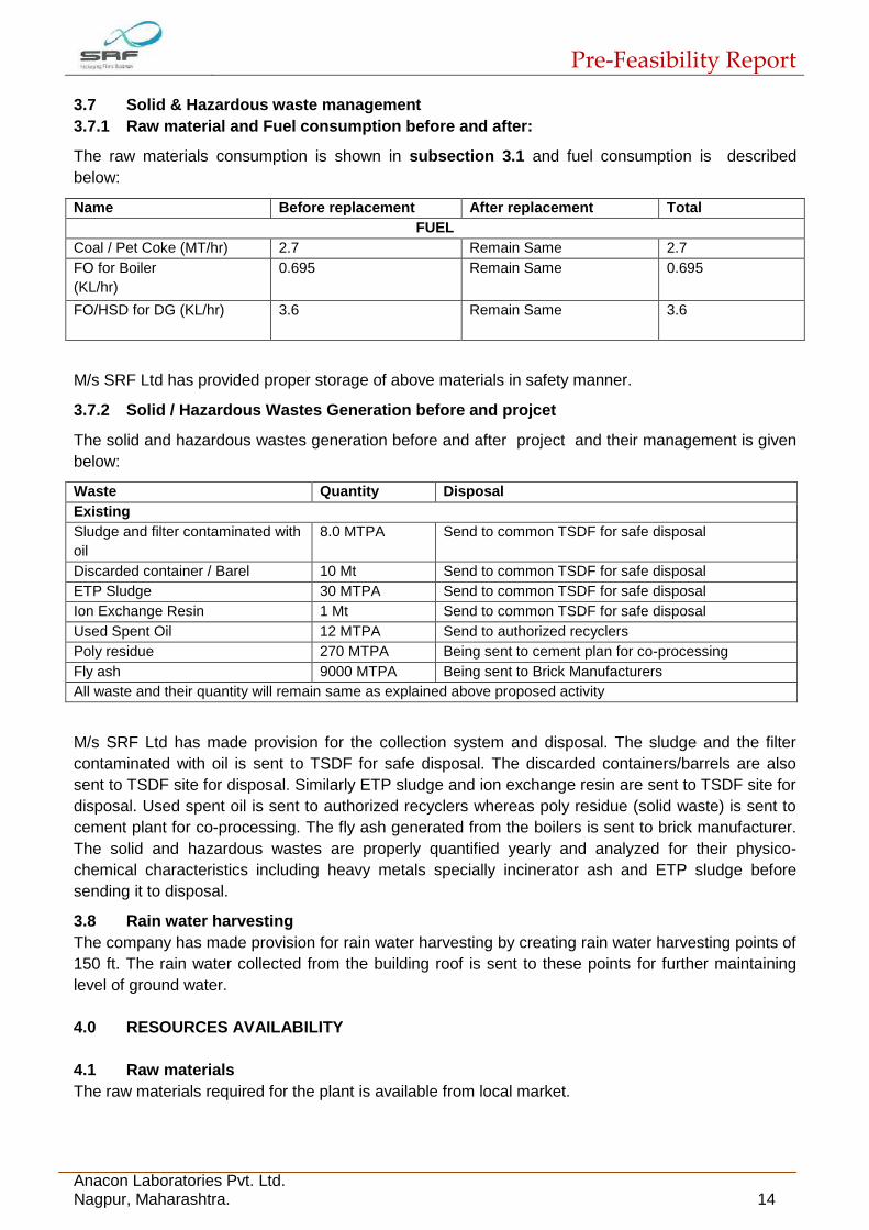
3.7 Solid & Hazardous waste management
3.7.1 Raw material and Fuel consumption before and after:
The raw materials consumption is shown in subsection 3.1 and fuel consumption is described
below:
Name Before replacement After replacement Total
FUEL
Coal / Pet Coke (MT/hr) 2.7 Remain Same 2.7
FO for Boiler
(KL/hr)
0.695 Remain Same 0.695
FO/HSD for DG (KL/hr)
3.6 Remain Same 3.6
M/s SRF Ltd has provided proper storage of above materials in safety manner.
3.7.2 Solid / Hazardous Wastes Generation before and projcet
The solid and hazardous wastes generation before and after project and their management is given
below:
Waste Quantity Disposal
Existing
Sludge and filter contaminated with
oil
8.0 MTPA Send to common TSDF for safe disposal
Discarded container / Barel 10 Mt Send to common TSDF for safe disposal
ETP Sludge 30 MTPA Send to common TSDF for safe disposal
Ion Exchange Resin 1 Mt Send to common TSDF for safe disposal
Used Spent Oil 12 MTPA Send to authorized recyclers
Poly residue 270 MTPA Being sent to cement plan for co-processing
Fly ash 9000 MTPA Being sent to Brick Manufacturers
All waste and their quantity will remain same as explained above proposed activity
M/s SRF Ltd has made provision for the collection system and disposal. The sludge and the filter
contaminated with oil is sent to TSDF for safe disposal. The discarded containers/barrels are also
sent to TSDF site for disposal. Similarly ETP sludge and ion exchange resin are sent to TSDF site for
disposal. Used spent oil is sent to authorized recyclers whereas poly residue (solid waste) is sent to
cement plant for co-processing. The fly ash generated from the boilers is sent to brick manufacturer.
The solid and hazardous wastes are properly quantified yearly and analyzed for their physico-
chemical characteristics including heavy metals specially incinerator ash and ETP sludge before
sending it to disposal.
3.8 Rain water harvesting
The company has made provision for rain water harvesting by creating rain water harvesting points of
150 ft. The rain water collected from the building roof is sent to these points for further maintaining
level of ground water.
4.0 RESOURCES AVAILABILITY
4.1 Raw materials
The raw materials required for the plant is available from local market.
Pre-Feasibility Report
Anacon Laboratories Pvt. Ltd. Nagpur, Maharashtra. 15
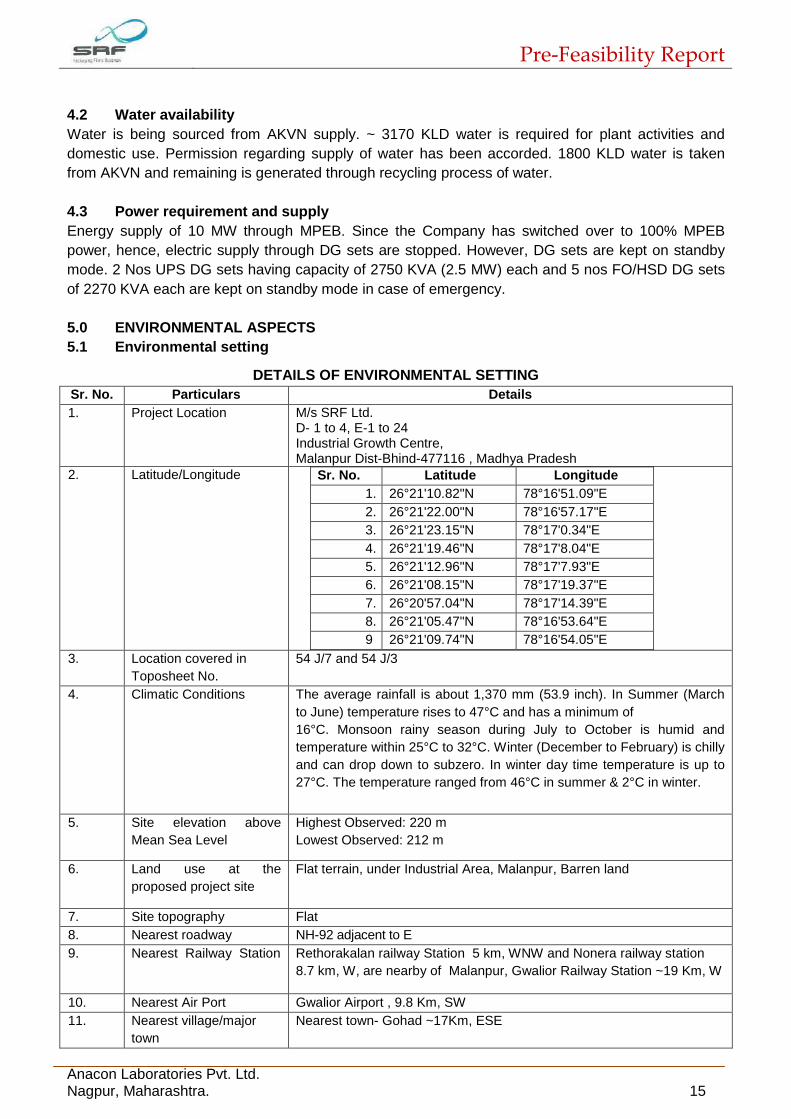
4.2 Water availability
Water is being sourced from AKVN supply. ~ 3170 KLD water is required for plant activities and
domestic use. Permission regarding supply of water has been accorded. 1800 KLD water is taken
from AKVN and remaining is generated through recycling process of water.
4.3 Power requirement and supply
Energy supply of 10 MW through MPEB. Since the Company has switched over to 100% MPEB
power, hence, electric supply through DG sets are stopped. However, DG sets are kept on standby
mode. 2 Nos UPS DG sets having capacity of 2750 KVA (2.5 MW) each and 5 nos FO/HSD DG sets
of 2270 KVA each are kept on standby mode in case of emergency.
5.0 ENVIRONMENTAL ASPECTS
5.1 Environmental setting
DETAILS OF ENVIRONMENTAL SETTING
Sr. No. Particulars Details
1. Project Location M/s SRF Ltd. D- 1 to 4, E-1 to 24 Industrial Growth Centre, Malanpur Dist-Bhind-477116 , Madhya Pradesh
2. Latitude/Longitude Sr. No. Latitude Longitude
1. 26°21'10.82"N 78°16'51.09"E
2. 26°21'22.00"N 78°16'57.17"E
3. 26°21'23.15"N 78°17'0.34"E
4. 26°21'19.46"N 78°17'8.04"E
5. 26°21'12.96"N 78°17'7.93"E
6. 26°21'08.15"N 78°17'19.37"E
7. 26°20'57.04"N 78°17'14.39"E
8. 26°21'05.47"N 78°16'53.64"E
9 26°21'09.74"N 78°16'54.05"E
3. Location covered in
Toposheet No.
54 J/7 and 54 J/3
4. Climatic Conditions The average rainfall is about 1,370 mm (53.9 inch). In Summer (March
to June) temperature rises to 47°C and has a minimum of
16°C. Monsoon rainy season during July to October is humid and
temperature within 25°C to 32°C. Winter (December to February) is chilly
and can drop down to subzero. In winter day time temperature is up to
27°C. The temperature ranged from 46°C in summer & 2°C in winter.
5. Site elevation above
Mean Sea Level
Highest Observed: 220 m
Lowest Observed: 212 m
6. Land use at the
proposed project site
Flat terrain, under Industrial Area, Malanpur, Barren land
7. Site topography Flat
8. Nearest roadway NH-92 adjacent to E
9. Nearest Railway Station Rethorakalan railway Station 5 km, WNW and Nonera railway station
8.7 km, W, are nearby of Malanpur, Gwalior Railway Station ~19 Km, W
10. Nearest Air Port Gwalior Airport , 9.8 Km, SW
11. Nearest village/major
town
Nearest town- Gohad ~17Km, ESE
Pre-Feasibility Report
Anacon Laboratories Pvt. Ltd. Nagpur, Maharashtra. 16
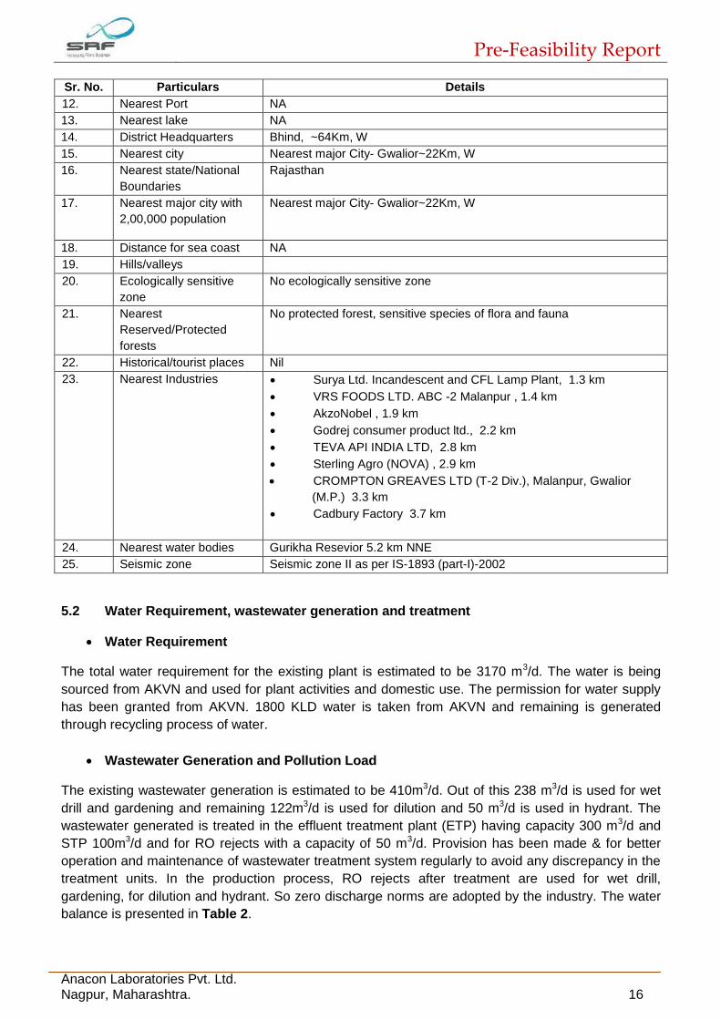
Sr. No. Particulars Details
12. Nearest Port NA
13. Nearest lake NA
14. District Headquarters Bhind, ~64Km, W
15. Nearest city Nearest major City- Gwalior~22Km, W
16. Nearest state/National
Boundaries
Rajasthan
17. Nearest major city with
2,00,000 population
Nearest major City- Gwalior~22Km, W
18. Distance for sea coast NA
19. Hills/valleys
20. Ecologically sensitive
zone
No ecologically sensitive zone
21. Nearest
Reserved/Protected
forests
No protected forest, sensitive species of flora and fauna
22. Historical/tourist places Nil
23. Nearest Industries Surya Ltd. Incandescent and CFL Lamp Plant, 1.3 km
VRS FOODS LTD. ABC -2 Malanpur , 1.4 km
AkzoNobel , 1.9 km
Godrej consumer product ltd., 2.2 km
TEVA API INDIA LTD, 2.8 km
Sterling Agro (NOVA) , 2.9 km
CROMPTON GREAVES LTD (T-2 Div.), Malanpur, Gwalior
(M.P.) 3.3 km
Cadbury Factory 3.7 km
24. Nearest water bodies Gurikha Resevior 5.2 km NNE
25. Seismic zone Seismic zone II as per IS-1893 (part-I)-2002
5.2 Water Requirement, wastewater generation and treatment
Water Requirement
The total water requirement for the existing plant is estimated to be 3170 m3/d. The water is being
sourced from AKVN and used for plant activities and domestic use. The permission for water supply
has been granted from AKVN. 1800 KLD water is taken from AKVN and remaining is generated
through recycling process of water.
Wastewater Generation and Pollution Load
The existing wastewater generation is estimated to be 410m3/d. Out of this 238 m3/d is used for wet
drill and gardening and remaining 122m3/d is used for dilution and 50 m3/d is used in hydrant. The
wastewater generated is treated in the effluent treatment plant (ETP) having capacity 300 m3/d and
STP 100m3/d and for RO rejects with a capacity of 50 m3/d. Provision has been made & for better
operation and maintenance of wastewater treatment system regularly to avoid any discrepancy in the
treatment units. In the production process, RO rejects after treatment are used for wet drill,
gardening, for dilution and hydrant. So zero discharge norms are adopted by the industry. The water
balance is presented in Table 2.
Pre-Feasibility Report
Anacon Laboratories Pvt. Ltd. Nagpur, Maharashtra. 17
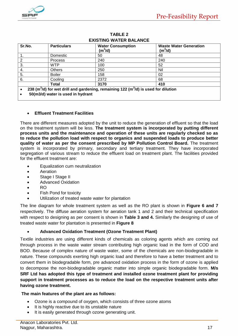
TABLE 2
EXISTING WATER BALANCE
Sr.No. Particulars Water Consumption (m
3/d)
Waste Water Generation (m
3/d)
1. Domestic 50 48
2 Process 240 240
3. WTP 100 52
4. Others 250 Nil
5. Boiler 158 02
6. Cooling 2372 68
Total 3170 410
238 (m3/d) for wet drill and gardening, remaining 122 (m
3/d) is used for dilution
50(m3/d) water is used in hydrant
Effluent Treatment Facilities
There are different measures adopted by the unit to reduce the generation of effluent so that the load on the treatment system will be less. The treatment system is incorporated by putting different process units and the maintenance and operation of these units are regularly checked so as to reduce the pollution load with respect to organics and suspended loads to produce better quality of water as per the consent prescribed by MP Pollution Control Board. The treatment system is incorporated by primary, secondary and tertiary treatment. They have incorporated segregation of various stream to reduce the effluent load on treatment plant. The facilities provided for the effluent treatment are:
Equalization cum neutralization
Aeration
Stage I Stage II
Advanced Oxidation
RO
Fish Pond for toxicity
Utilization of treated waste water for plantation
The line diagram for whole treatment system as well as the RO plant is shown in Figure 6 and 7
respectively. The diffuse aeration system for aeration tank 1 and 2 and their technical specification
with respect to designing as per consent is shown in Table 3 and 4. Similarly the designing of use of
treated waste water for plantation is presented in Figure 8
Advanced Oxidation Treatment (Ozone Treatment Plant)
Textile industries are using different kinds of chemicals as coloring agents which are coming out
through process in the waste water stream contributing high organic load in the form of COD and
BOD. Because of complex nature of waste water, some of the chemicals are non-biodegradable in
nature. These compounds exerting high organic load and therefore to have a better treatment and to
convert them in biodegradable form, pre advanced oxidation process in the form of ozone is applied
to decompose the non-biodegradable organic matter into simple organic biodegradable form. M/s
SRF Ltd has adopted this type of treatment and installed ozone treatment plant for providing
support in treatment processes as to reduce the load on the respective treatment units after
having ozone treatment.
The main features of the plant are as follows:
Ozone is a compound of oxygen, which consists of three ozone atoms
It is highly reactive due to its unstable nature
It is easily generated through ozone generating unit.

Pre-Feasibility Report
Anacon Laboratories Pvt. Ltd. Nagpur, Maharashtra. 18
It attacks various micro-organisms killing them almost instantly
It removes taste, odor and color from wastewater This eliminates addition of any chemical to water
Moreover, it reduces the pollution load on the subsequent treatment system
Pre-oxidation is preferable for decreasing initial pollution load in the wastewater
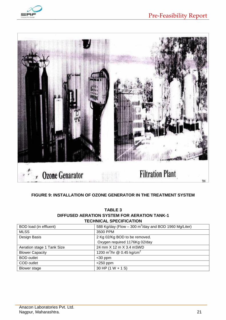
The ozone generator installed by M/s SRF Ltd as a part of treatment system is shown in Figure 9
FIGURE 6: ETP FLOW DIAGRAM

Pre-Feasibility Report
Anacon Laboratories Pvt. Ltd. Nagpur, Maharashtra. 19
FIGURE 7: RO SYSTEM IN THE TREATMENT PLANT

Pre-Feasibility Report
Anacon Laboratories Pvt. Ltd. Nagpur, Maharashtra. 20
FIGURE 8: DESIGNING FOR USE OF TREATED WASTE WATER FOR PLANTATION
Pre-Feasibility Report
Anacon Laboratories Pvt. Ltd. Nagpur, Maharashtra. 21
FIGURE 9: INSTALLATION OF OZONE GENERATOR IN THE TREATMENT SYSTEM
TABLE 3
DIFFUSED AERATION SYSTEM FOR AERATION TANK-1
TECHNICAL SPECIFICATION
BOD load (in effluent) 588 Kg/day (Flow – 300 m3/day and BOD 1960 Mg/Liter)
MLSS 3500 PPM
Design Basis 2 Kg 02/Kg BOD to be removed.
Oxygen required 1176Kg 02/day
Aeration stage 1 Tank Size 24 mm X 12 m X 3.4 mSWD
Blower Capacity 1200 m3/hr @ 0.45 kg/cm
2
BOD outlet <30 ppm
COD outlet <250 ppm
Blower stage 30 HP (1 W + 1 S)

Pre-Feasibility Report
Anacon Laboratories Pvt. Ltd. Nagpur, Maharashtra. 22
TABLE 4
DIFFUSED AERATION SYSTEM FOR AERATION TANK-2
TECHNICAL SPECIFICATION
BOD load 10 kg/day
Flow 50 m3/day
BOD in 200 mg/Liter
BOD out <30 mg/liter
MLSS 3500 PPM
Design Basis removed 2 kg O2/Kg BOD to be
Aeration stage 1 Tank size 11.2 m X 5.6 m X 2.75 m SWO
Blower capacity 180 m3/hr @ 0.38 Kg/cm
2
BOD out < 30 PPM
Blower Stage 5 HP (1 W + 1S)
Wastewater pollution load
The wastewater generated (from 2009-2015) is characterized and pollution load is estimated as
presented in Table 5. It is observed that during 2009 to 2015 the pollution load exerted in the form of
suspended load and organic load in the form of BOD and COD exerted was 17.07 kg/day, 4.25
kg/day and 38.35 kg/day respectively with a pH ranged from 7.1 to 8.3. The overall pollution load
after treatment is well within the permissible load given by MPPCB as per consent. The
company is adopting zero discharged norms and not discharging anywhere in the surface
stream or ground water. Hence no impact is envisaged as surface and ground water.
TABLE 5
WATER POLLUTION LOAD
WATER SAMPLE: TREATED EFFLUENT CHARACTERISTICS
(Year 2009-2015)
Date SS BOD COD pH Waste water generation
(kg/day) (m3/day)
June 2009 5.11 1.75 8.29 8.3 72
July 2009 6.52 2.10 13.76 7.4 89
Aug 2009 6.20 2.19 13.22 7.1 87
May 2010 25.94 8.95 45.61 7.3 362
June 2010 21.01 7.21 38.64 7.3 322
July 2010 22.71 8.28 44.99 7.1 370
May 2011 19.12 4.84 27.17 7.53 209
June 2011 19.45 6.45 38.90 7.22 367
July 2011 19.36 2.04 36.42 7.17 301
May 2012 25.31 5.72 45.76 7.5 286
June 2012 9.18 2.24 14.78 7.9 112
July 2012 10.49 2.08 27.02 8.2 163
May 2013 24.12 5.37 40.32 7.6 336
June 2013 29.02 5.41 41.98 7.6 366
July 2013 7.63 4.82 57.93 7.4 355
May 2014 28.19 5.48 77.72 7.6 381
June 2014 31.9 5.06 84.2 7.8 384
July 2014 25.43 4.40 67.39 7.8 324
May 2015 10.32 2.88 42.2 7.6 240
June 2015 9.72 1.56 22.76 7.7 118.56
July 2015 7.43 1.9 18.4 7.5 100
Aug 2015 11.42 2.87 36.4 7.7 175
Average 17.07 4.25 38.35 Range 7.1-8.3 250.88

Pre-Feasibility Report
Anacon Laboratories Pvt. Ltd. Nagpur, Maharashtra. 23
5.3 Power requirement
Energy supply of 10 MW through MPEB. 2 Nos UPS DG sets having capacity of 2.5 MW each. Both
DG sets are equipped with acoustic enclosures. 5 nos DG of 2270 KVS each are also installed and
kept as stand by.
5.4 Solid and Hazardous waste Generation
The major hazardous wastes generation from the plant is in the form of ETP sludge, Oil soaked
cotton waste and solid wastes are Fly ash and Poly-residue. The quantification of hazardous wastes
generated from the plant has been estimated. During the year 2009-2014 the generation of used oil
was estimated to be 2.31 KL to 5.88 KL/yr and it is also given to approved recyclers or vendors. The
quantity of empty containers is in the range of 118 to 1009 Nos/yr. There is tremendous decrease in
quantity of empty containers in the subsequent years. However all these empty containers are sent
back to suppliers. The ETP sludge generated from the wastewater treatment system is
estimated to be 4.32 to 21.36 MT/Yr and sent to TSDF facility. It is observed that the other
hazardous wastes like oil sludge from storage tank, residue containing oil and residue of
contaminated organic solvent are not generated from the year 2009-2015. At present all the
hazardous wastes generated are properly quantified, analyzed for their physico-chemical
characteristics and heavy metals contamination and then disposed of in TSDF facility as well as
recycled to the approved vendors.
5.4.1 Measures taken by the company for handling, Transportation and Disposal of
Hazardous solid / liquid wastes
M/s SRF Ltd is already handling various Hazardous waste and chemicals. The employees are well trained about handling, transportation/ disposal of solid/ hazardous waste/ chemicals. The various precautionary measures are being taken up for handling, transportation/ disposal of solid/ hazardous waste/ chemicals which are as follows:
Depending on the properties of chemical storage facilities are provided. Some of the chemicals / solvents which are hazardous in nature are stored at a refrigerated condition
The chemicals are transported in a dedicated vehicles with proper measures
The chemicals are transported in drums. The drums are properly labeled and stored properly in a raw material godown and protected for direct sunlight and rain.
Transport emergency card is used for transportation of solid, hazardous waste and chemicals.
All employees are given regular/ (periodical) training in uses and handling of chemicals as well as Hazardous waste generated from the plant.
Material Safety data sheets (MSDS) are available with the plant.
All employees are given personal protective equipment (PPE)
Closed transport system is provided for hazardous / toxic chemicals
Specific instructions are displayed at various points of Do’s and Don’ts
Safety guidelines are prepared and given to all employees
Onsite emergency plan is prepared and being adopted regularly
Mock drill are conducted regularly
Occupational Health Centre is also available at the unit
Pre-employment and routine medical examination is done for all the employees
Annual medical examination is done through experts.
5.5 Noise Generation
Noise generation from the plant is only due to DG sets. However these are occasionally required to
be run in case of power failure. Proper provision has been made with enclosures to restrict noise
levels up to permissible levels. All employees and workers are provided with ear muffs / plugs as a

Pre-Feasibility Report
Anacon Laboratories Pvt. Ltd. Nagpur, Maharashtra. 24
safety measures. There is massive plantation in and around the plant site which is also helping to
attenuate the noise levels. The noise level was monitored for DG sets are found to be within 75 dB
(A) at 1 meter from the enclosure surface.
5.6 Air emission
The air emission i.e. particulate matter (PM) is through stack only which is monitored regularly. The
particulate matter emission is estimated as 96 mg/ Nm3 which is under the prescribed limit of MPPCB
norms. Ambient air quality is also monitored regularly and levels are as follows:
PM10 - 96 mg/Nm3
SO2 - 23.28 µg/m3
NOx - 31.58 µg/m3
These are well within the AAQMS.
It is to be mentioned here that there is tremendous reduction in Air pollution load. The
reduction in pollution load is leading to the appropriate measures taken by the company by
installation of vapour absorption machines, installation of gas operated engine and use of
natural gas for electricity generation and closure of DG sets and putting up in stand by
position.
5.7 Plantation
M/s SRF has developed green belt and plantation within the plant premises. Around 17632
trees/shrubs are planted and it is maintained properly. Four big lawns are also developed in this
premises which are infront of Admin building, reception area, ETP and RO. Under EMP- around 500
trees/year are planted
Area: 272109.5 sq.mt.
5.8 Waste Disposal (Liquid & Solid)
Most of the liquid effluent is recycled in the process. The rest is treated in ETP and treated waste is
used for plantation and horticulture purposes. The company is following zero discharge norms. Solid
wastes from the process are mostly recycled or reutilized within the unit. Hazardous wastes are
collected properly and sent to common TSDF.
Domestic Solid wastes are segregated within the plant for its organics and Inorganics. Organics are
sent for composting whereas Inorganics are disposed through selling to the approved vendors or
recyclers.
6.0 PROJECT SCHEDULE AND COST ESTIMATES
6.1 Project schedule
The project is fully developed for the production of 33000 MT/Annum of Nylon Industrial Yarn and
23,300 MT/Annum of Nylon Tyre Cord Fabric, Power generation (10 MW), Coal based steam boiler
and thermic Fluid Heater (10 TPH, 1.5 Million KCAL). The plant is running and engaged in
production. The company is proposed for debottleneck the plant to increase production capacity
and modification for takeout nylon chips as separate product
Pre-Feasibility Report
Anacon Laboratories Pvt. Ltd. Nagpur, Maharashtra. 25
6.2 Cost estimates
Proposed: 130 crores, Existing 529 Crores,
6.3 Economic viability
Considering the demand of the product in market, and the production rate, the company is yielding
profit. With a wide range of products M/s SRF Pvt. Ltd. is not only the largest manufacturer of
technical textiles in India but also enjoys a global leadership for most of the products under this
business.
7.0 CORPORATE SOCIAL RESPONSIBILITY (CSR) POLICY
The company is actively involved in CSR related activities, thorough SRF foundation run by M/s SRF
limited. Budgetary provision has been made in the financial year to spent about 7 crores as a
corporate social responsibility.

Pre-Feasibility Report
Anacon Laboratories Pvt. Ltd. Nagpur, Maharashtra. 26
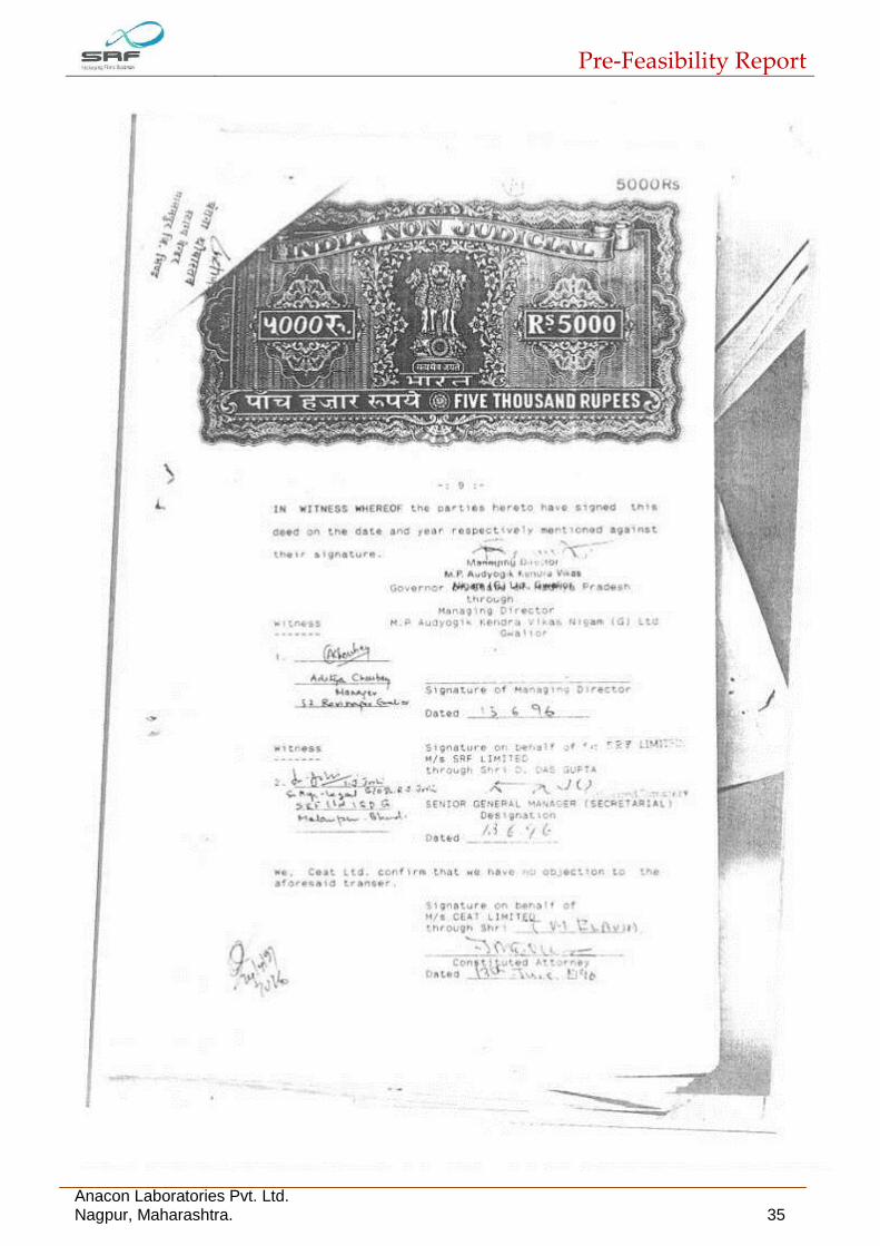
Annexure -I
Land Documents

Pre-Feasibility Report
Anacon Laboratories Pvt. Ltd. Nagpur, Maharashtra. 27

Pre-Feasibility Report
Anacon Laboratories Pvt. Ltd. Nagpur, Maharashtra. 28

Pre-Feasibility Report
Anacon Laboratories Pvt. Ltd. Nagpur, Maharashtra. 29

Pre-Feasibility Report
Anacon Laboratories Pvt. Ltd. Nagpur, Maharashtra. 30

Pre-Feasibility Report
Anacon Laboratories Pvt. Ltd. Nagpur, Maharashtra. 31

Pre-Feasibility Report
Anacon Laboratories Pvt. Ltd. Nagpur, Maharashtra. 32

Pre-Feasibility Report
Anacon Laboratories Pvt. Ltd. Nagpur, Maharashtra. 33

Pre-Feasibility Report
Anacon Laboratories Pvt. Ltd. Nagpur, Maharashtra. 34
Pre-Feasibility Report
Anacon Laboratories Pvt. Ltd. Nagpur, Maharashtra. 35