Embed Size (px)
Citation preview
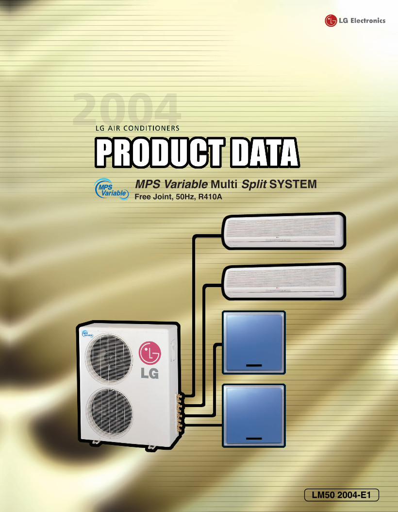
LM50 2004-E1
MPS Variable Multi Split SYSTEMFree Joint, 50Hz, R410A
2004 Product Data 1
General Description
Thank you very much for your special patronage of LG air-conditioners.
A high-grade, high-quality, advanced individual air-conditioning system that is able to respond to expanding,
more sophisticated housing environment needs.
LG Electronics Inc., which has been a top air conditioner maker for the three consecutive years, has developed
"MPS(Multi Power System) Variable Multi Split" system that can efficiently control air-conditioning in a better
way. Unlike traditional multi-type units, "MPS Variable Multi Split" is a next-generation multi type air-condition-
er designed to be installed under any circumstance.
MPS control provides comfortable and convenient environment as small capacity compressor is operating con-
tinuously compared to conventional ON/OFF cycle compressor. A number of indoor units can be linked to an
outdoor units so that each room can be individually air-conditioned.
This can be easily installed in a small space area, and is energy saving since the cooling of each room individu-
ally controlled.
A lot of information regarding the design and the installation of "MPS Variable Multi Split" system is included in
this publication. We hope that with this information you would become an expert of the "MPS Variable Multi
Split" system and be more comprehensive to the system.
LG Electronics Inc.Air Conditioning Division

2 MPS Variable Multi Split System(50Hz, R410A)
2004 Product Data 3
LG Airconditioners Product Data
TABLE OF CONTENTS
Table of contents Page
Part 1 Features...............................................................................................7
Part 2 MPS Variable Multi-Split system (R410A).......................................11

4 MPS Variable Multi Split System(50Hz, R410A)

2004 Product Data 5
Part 1Features
6 MPS Variable Multi Split System(50Hz, R410A)
Features & Benefit
MPS(Multi Power System) Variable Control : (Except A2UC146FA0,A2UH146FA0)Big Energy Saving with MPS Variable Control
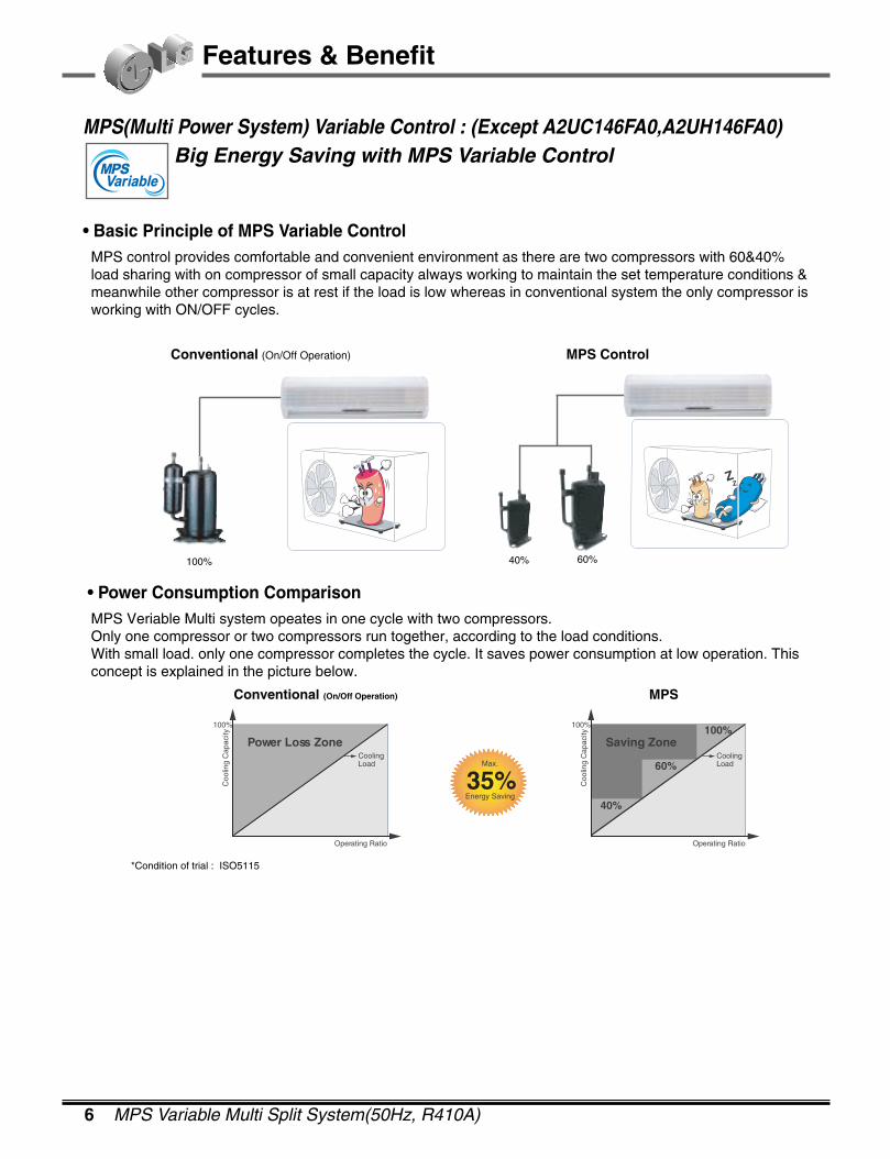
• Basic Principle of MPS Variable ControlMPS control provides comfortable and convenient environment as there are two compressors with 60&40%load sharing with on compressor of small capacity always working to maintain the set temperature conditions &meanwhile other compressor is at rest if the load is low whereas in conventional system the only compressor isworking with ON/OFF cycles.
• Power Consumption ComparisonMPS Veriable Multi system opeates in one cycle with two compressors.Only one compressor or two compressors run together, according to the load conditions.With small load. only one compressor completes the cycle. It saves power consumption at low operation. Thisconcept is explained in the picture below.
Operating Ratio
100%
Coo
ling
Cap
acity
Power Loss ZoneCoolingLoad
Operating Ratio
100%
Coo
ling
Cap
acity
Saving Zone
40%
60%
100%
CoolingLoad
35%Energy Saving
Max.
Conventional (On/Off Operation) MPS
*Condition of trial : ISO5115
100% 40% 60%
Conventional (On/Off Operation) MPS Control

2004 Product Data 7
Features & Benefit
90(Min)0
100
200
300
400
500(ppm)
6030
Nano Filter
+
+
+
+
+
+
+
+
+
+
+
+
+
+
+
+
Normal Filter
Air Purifying System- It not only removes microscopic contaminants & dust, but it
also removes house mites, pollen, and pet fur to help pre-vent allergic diseases like asthma.It provides odor free, dustfree and allergy free air.
• Effect of carbon Nano BallDeodorizing efficieny: 8~10times compared to conventionalcarbon filter.
• What is Carbon Nano Ball?Nano(1/1 Bil) ball structure, (200~500nm) consisted of car-bon, is adopted as deodorizing material first in the world.
Nasty smellDeodorizing
FormaldehydeDeodorizing
V.O.C.Deodorizing
Composition of Triple Deodorizing Filter
¥ Remove odor !¥ Restrain mildew !¥ Keep Performance ! (Durability)¥ Save time to clean up.
AfterBefore Effect
In 30 minutes "Auto-Clean" makes the inner part of Air conditioner Dry
After Cooling Operation, Start "Auto-Clean" automatically
Triple Deodorizing Filter : - Deodorizing efficiency
: 10% up compared to conventional Deodorizing Filter
Auto Cleaning System :- Auto Clean helps to remove odor and save clean-up
time. After using air-conditioner, “Auto Clean” makes the
inner part of Air conditioner dry in 30 min. It removes
moisture and mould so you can enjoy odor-free air and
save time to clean up.
8 MPS Variable Multi Split System(50Hz, R410A)
Features & Benefit
Vertical TemperatureDifference
Horizontal TemperatureDifference
Improved value of the 3-Dimensional Cooling
Time ReachingTemperature
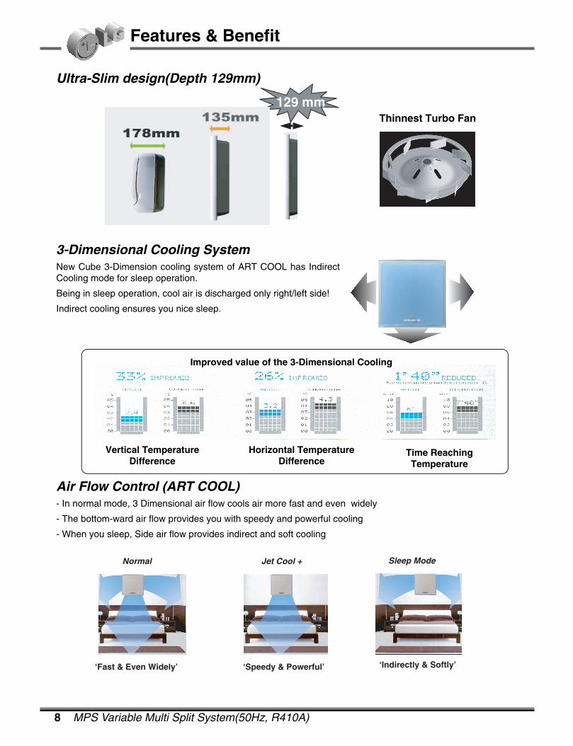
Thinnest Turbo Fan129 mm
‘Fast & Even Widely’
Normal
‘Speedy & Powerful’
Jet Cool +
‘Indirectly & Softly’
Sleep Mode
Ultra-Slim design(Depth 129mm)
3-Dimensional Cooling SystemNew Cube 3-Dimension cooling system of ART COOL has IndirectCooling mode for sleep operation.
Being in sleep operation, cool air is discharged only right/left side!
Indirect cooling ensures you nice sleep.
Air Flow Control (ART COOL)- In normal mode, 3 Dimensional air flow cools air more fast and even widely
- The bottom-ward air flow provides you with speedy and powerful cooling
- When you sleep, Side air flow provides indirect and soft cooling
Improved value of the 3-Dimensional Cooling
Vertical TemperatureDifference
Horizontal TemperatureDifference
Time ReachingTemperature
2004 Product Data 9
Features & Benefit
Environment Friendly Refrigerant :- LG Air conditioners uses environment friendly refrigerant. Which don't do any harm to the environment.
Jet Cool: - In this mode very quick and fast cooling is done. The unit will continue to supply high velocity air for 30 min-
utes, untill the room temperature reaches 18°C. After 30 minutes, unit will supply air at the set fan speed
whether indoor temperature has reached 18°C or not.
Self Diagnosis Function:- This function provides diagnosis of the unit. Blinking of the operation LED of the indoor unit means there is
some error.
Cooling, Heating & Fan Operation:- LG multi air conditioners can provide cooling, heating & fan operation. In the cooling mode, it cools the air with
an operation range of 18~30°C. In the heating mode, it heats the air with an operation range of 16~30°C. In
the fan operation mode, only indoor fan will run at the selected speed, outdoor fan and compressor will be off.
LCD Wireless Remocon:- It provides ease of control.
Auto Restart Operation :- When there is electricity failure the unit sharts off. After resumption of the power, unit will start in the same
mode as prior to the power failure. Memorized condition are on / off condition, operating mode (cooling/heat-
ing), set temperature and fan speed. The unit will memorize the above conditions and start with same memo-
rized condition.
Hot Start Function :- During starting of the unit in the heating mode it prevents cold air blow from the unit.It starts the indoor fan only
after indoor unit pipe temperature reaches a preset value(28°C). When indoor unit pipe temperature has
reached 28°C, then for initial 1 minute the indoor fan runs at low speed and after that at the set fan speed.
Defrost / Deicing :- In the heating mode, it prevents the ice formation on the outdoor unit. Sensing the outdoor piping temperature,
If it is lower than some preset value then the outdoor fan stops and compressor continues to run till a particular
temperature is reached. Thereby preventing the frost on the outdoor coil. After reaching a particular high tem-
perature outdoor fan again starts.
Time Delay Safety function:-It delays restarting of the compressor by three minutes thereby preventing damage to the compressor .

10 MPS Variable Multi Split System(50Hz, R410A)

2004 Product Data 11
Part 2MPS Variable Multi-Split System
R410A, Cooling Only/Heat PumpAMNC076LQL0 AMNC096AP*1
AMNC096LQL0 AMNC126AP*1
AMNC126LRL0
AMNC186LTL0
AMNC246LTL0
AMNH076LQL0 AMNH096AP*1
AMNH096LQL0 AMNH126AP*1
AMNH126LRL0
AMNH186LTL0
AMNH246LTL0
A2UC146FA0
A2UC186FA0
A3UC216FA0
A4UC306FA0
A2UH146FA0
A2UH186FA0
A3UH216FA0
A4UH306FA0
1. Power Supply .................................................................................................................12
2. Model Number Nomenclature .......................................................................................13
3. Outline of System...........................................................................................................14
4. List of Functions .............................................................................................................16
5. Specifications ................................................................................................................17
6. Combination Table ........................................................................................................21
7. Dimensional Drawings ...................................................................................................27
8. Wiring Diagrams.............................................................................................................33
9. Piping Diagrams.............................................................................................................43
10. Capacity Tables............................................................................................................49
11. Operation Limit.............................................................................................................64
12. Air Velocity and Temperature Distributions(Reference Data) .......................................65
13. Sound Levels ...............................................................................................................66
14. Installation ....................................................................................................................69
15. Function of Remote Controller ....................................................................................76
12 MPS Variable Multi Split System(50Hz, R410A)
1. Power Supply
Type Outdoor Unit Power Supply
Cooling Only
1Ø, 220~240V, 50Hz
Heat Pump
Note : Power Supply Intake ; Outdoor Unit Only
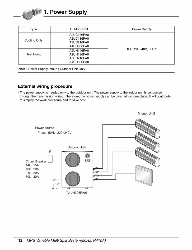
External wiring procedure- The power supply is needed only to the outdoor unit. The power supply to the indoor unit Is conducted
through the transmission wiring. Therefore, the power supply can be given at just one place. It will contributeto simplify the work procedure and to save cost.
Circuit Breaker14k : 15A18k : 20A21k : 20A30k : 30A
[Outdoor Unit]
[A4UH306FA0]
[Indoor Unit]
Power source
1 Phase, 50Hz, 220~240V
A2UC146FA0A2UC186FA0A3UC216FA0A4UC306FA0A2UH146FA0A2UH186FA0A3UH216FA0A4UH306FA0
2004 Product Data 13
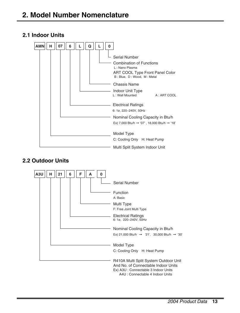
2. Model Number Nomenclature
2.1 Indoor Units
2.2 Outdoor Units
AMN H 607 QL L 0
Chassis Name
Serial Number
Combination of Functions
ART COOL Type Front Panel Color
L : Wall Mounted A : ART COOL
B : Blue, D : Wood, M : Metal
L : Nano Plasma
Indoor Unit Type
Electrical Ratings6: 1ø, 220~240V, 50Hz
Nominal Cooling Capacity in Btu/hEx) 7,000 Btu/h � ‘07’ , 18,000 Btu/h � ‘18’
Model Type
C: Cooling Only H: Heat Pump
Multi Split System Indoor Unit
A3U H 621 F A 0
Multi TypeF: Free Joint Multi Type
FunctionA: Basic
Serial Number
Electrical Ratings6: 1ø, 220~240V, 50Hz
Nominal Cooling Capacity in Btu/hEx) 21,000 Btu/h '21', 30,000 Btu/h � '30' �
Model TypeC: Cooling Only H: Heat Pump
R410A Multi Split System Outdoor UnitAnd No. of Connectable Indoor UnitsEx) A3U : Connectable 3 Indoor Units A4U : Connectable 4 Indoor Units
14 MPS Variable Multi Split System(50Hz, R410A)
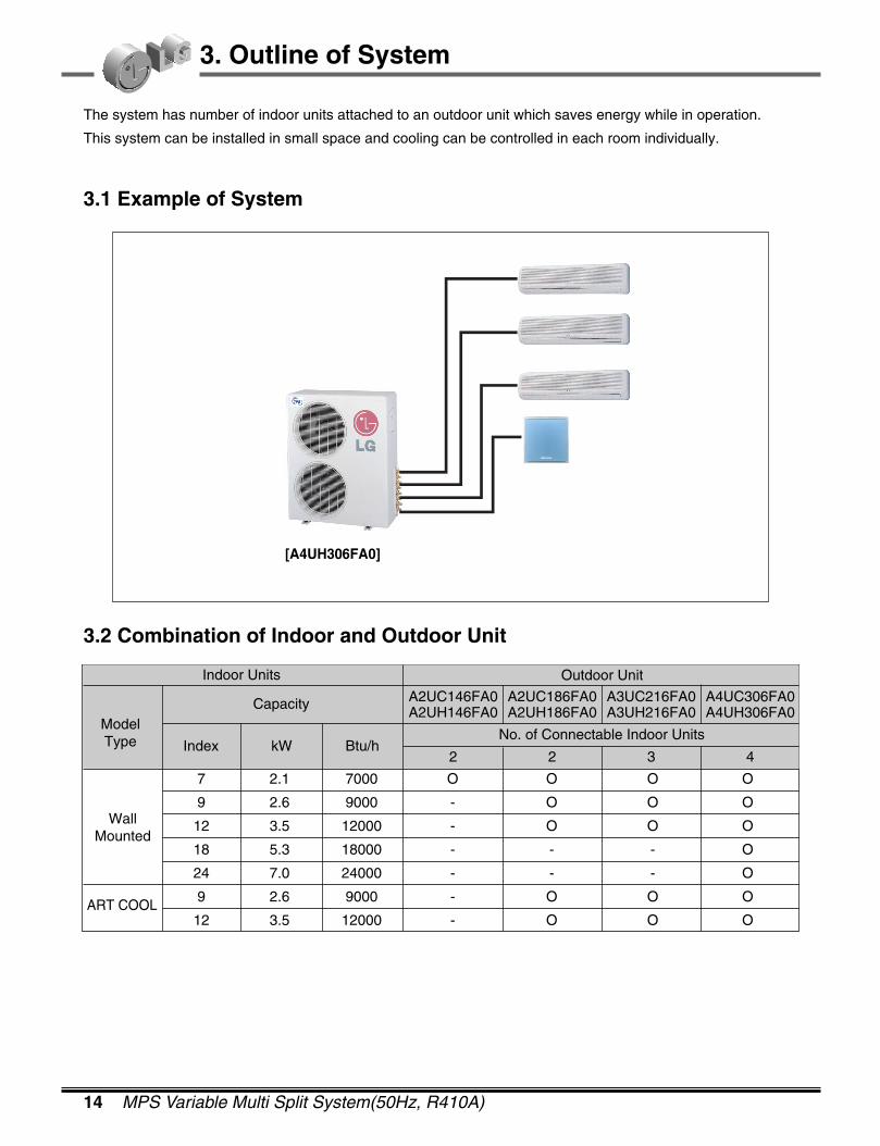
3. Outline of System
The system has number of indoor units attached to an outdoor unit which saves energy while in operation.
This system can be installed in small space and cooling can be controlled in each room individually.
3.1 Example of System
[A4UH306FA0]
3.2 Combination of Indoor and Outdoor Unit
Indoor Units
CapacityModelType
WallMounted
ART COOL
Index kW Btu/h
Outdoor Unit
A2UC146FA0A2UH146FA0
A2UC186FA0A2UH186FA0
A3UC216FA0A3UH216FA0
A4UC306FA0A4UH306FA0
2 2 3 4
No. of Connectable Indoor Units
7 2.1 7000 O O O O
9 2.6 9000 - O O O
12 3.5 12000 - O O O
18 5.3 18000 - - - O
24 7.0 24000 - - - O
9 2.6 9000 - O O O
12 3.5 12000 - O O O
2004 Product Data 15
3. Outline of System
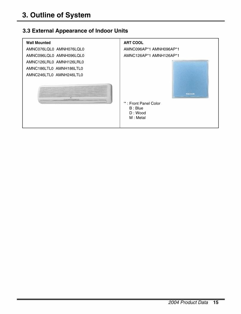
3.3 External Appearance of Indoor Units
Wall Mounted
AMNC076LQL0 AMNH076LQL0
AMNC096LQL0 AMNH096LQL0
AMNC126LRL0 AMNH126LRL0
AMNC186LTL0 AMNH186LTL0
AMNC246LTL0 AMNH246LTL0
ART COOL
AMNC096AP*1 AMNH096AP*1
AMNC126AP*1 AMNH126AP*1
'* : Front Panel ColorB : BlueD : WoodM : Metal

16 MPS Variable Multi Split System(50Hz, R410A)
4. List of Functions
ModelFeatures
Airflow Direction Control(Left & Right) Manual Manual Manual ManualAirflow Direction Control(Up & Down) Automatic Automatic Automatic AutomaticAirflow Outlet 1 3 1 3Airflow Steps(Fan / Cool / Heat) 3/4/3 3/4/3 3/4/3 3/4/3Auto Changeover(Operation) - - - -Auto Cleaning - O - OAuto Restart Operation O O O OCentral Control Accessory Accessory Accessory AccessoryCHAOS Wind(Auto Wind) O O O OChild Lock Function - - - -Cooling & Heating Fan Operation O(not heating) O(not heating) O ODeice Control - - O ODeodorizing Filter O(Triple) - O(Triple) -Drain Pump - - - -E.S.P Control - - - -Forced Operation O O O OGroup Control - - - -High Ceiling Operation - - - -Hot Start Function - - O OJet Cool O O O ONano Plasma Air Purifying Filter O O O OPlasma Heat Exchanger - - - -Prefilter(Washable / Anti-fungus) O O O OSelf Diagnosis Function O O O OSleep Mode Operation O O O OSoft Dry Operation O O O OSoft Start Function - - - -Test Function O O O OTime Delay Safety Function O O O OTimer(24 Hour, On/Off) O O O OTimer(Weekly, On/Off) - - - -Two Thermistor Control - - - -Wired LCD Remote Control - - - -Wireless LCD Remote Control O O O OZero Stanby Power - - - -Zone Control - - - -
AMNC-LQ/LR/LT AMNC-AP AMNH-LQ/LR/LT AMNH-AP
Notes :
O : BasicOptional : Factory-InstalledAccessory : Field-Installed- : Not available on this system
2004 Product Data 17
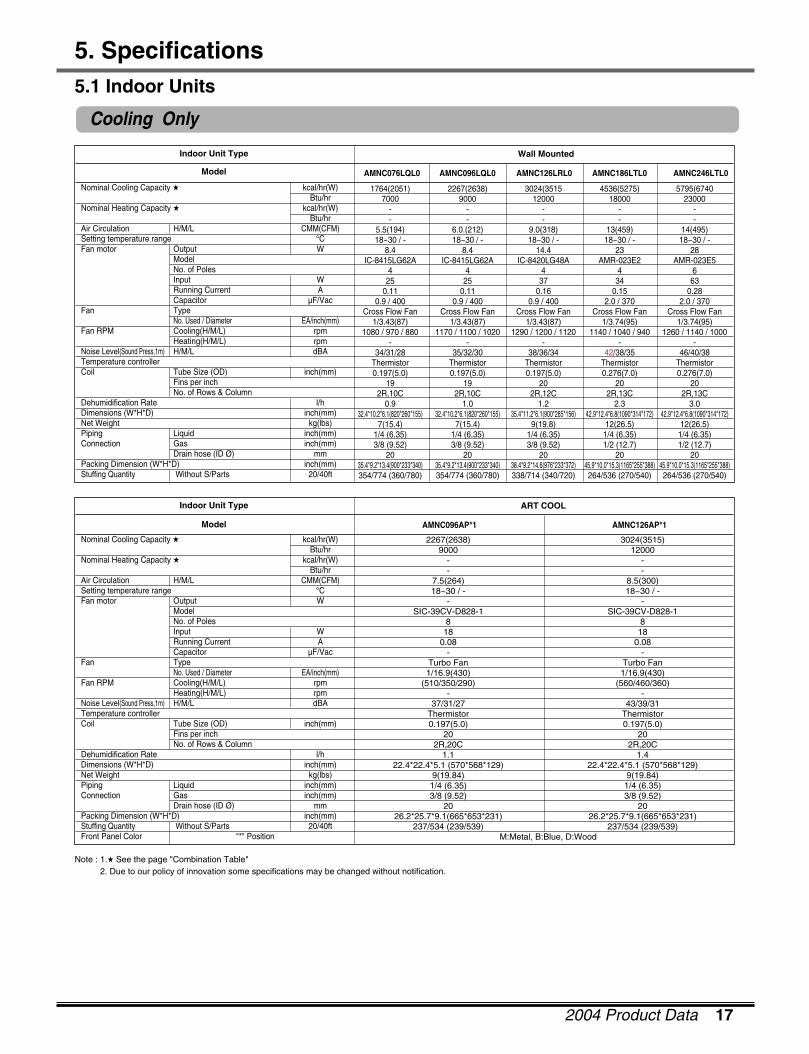
5. Specifications
1764(2051) 2267(2638) 3024(3515 4536(5275) 5795(67407000 9000 12000 18000 23000
- - - - -- - - - -
5.5(194) 6.0.(212) 9.0(318) 13(459) 14(495)18~30 / - 18~30 / - 18~30 / - 18~30 / - 18~30 / -
8.4 8.4 14.4 23 28IC-8415LG62A IC-8415LG62A IC-8420LG48A AMR-023E2 AMR-023E5
4 4 4 4 625 25 37 34 63
0.11 0.11 0.16 0.15 0.280.9 / 400 0.9 / 400 0.9 / 400 2.0 / 370 2.0 / 370
Cross Flow Fan Cross Flow Fan Cross Flow Fan Cross Flow Fan Cross Flow Fan1/3.43(87) 1/3.43(87) 1/3.43(87) 1/3.74(95) 1/3.74(95)
1080 / 970 / 880 1170 / 1100 / 1020 1290 / 1200 / 1120 1140 / 1040 / 940 1260 / 1140 / 1000- - - - -
34/31/28 35/32/30 38/36/34 42/38/35 46/40/38Thermistor Thermistor Thermistor Thermistor Thermistor0.197(5.0) 0.197(5.0) 0.197(5.0) 0.276(7.0) 0.276(7.0)
19 19 20 20 202R,10C 2R,10C 2R,12C 2R,13C 2R,13C
0.9 1.0 1.2 2.3 3.032.4*10.2*6.1(820*260*155) 32.4*10.2*6.1(820*260*155) 35.4*11.2*6.1(900*285*156) 42.9*12.4*6.8(1090*314*172) 42.9*12.4*6.8(1090*314*172)
7(15.4) 7(15.4) 9(19.8) 12(26.5) 12(26.5)1/4 (6.35) 1/4 (6.35) 1/4 (6.35) 1/4 (6.35) 1/4 (6.35)3/8 (9.52) 3/8 (9.52) 3/8 (9.52) 1/2 (12.7) 1/2 (12.7)
20 20 20 20 2035.4*9.2*13.4(900*233*340) 35.4*9.2*13.4(900*233*340) 38.4*9.2*14.6(976*233*372) 45.9*10.0*15.3(1165*255*388) 45.9*10.0*15.3(1165*255*388)354/774 (360/780) 354/774 (360/780) 338/714 (340/720) 264/536 (270/540) 264/536 (270/540)
Nominal Cooling Capacity � kcal/hr(W)Btu/hr
Nominal Heating Capacity � kcal/hr(W)Btu/hr
Air Circulation H/M/L CMM(CFM)Setting temperature range °CFan motor Output W
ModelNo. of PolesInput WRunning Current ACapacitor µF/Vac
Fan TypeNo. Used / Diameter EA/inch(mm)
Fan RPM Cooling(H/M/L) rpmHeating(H/M/L) rpm
Noise Level(Sound Press,1m) H/M/L dBATemperature controllerCoil Tube Size (OD) inch(mm)
Fins per inchNo. of Rows & Column
Dehumidification Rate l/hDimensions (W*H*D) inch(mm)Net Weight kg(lbs)Piping Liquid inch(mm)Connection Gas inch(mm)
Drain hose (ID Ø) mmPacking Dimension (W*H*D) inch(mm)Stuffing Quantity Without S/Parts 20/40ft
Wall Mounted
AMNC076LQL0 AMNC096LQL0 AMNC126LRL0 AMNC186LTL0 AMNC246LTL0
Indoor Unit Type
Model
Note : 1.� See the page "Combination Table"2. Due to our policy of innovation some specifications may be changed without notification.
5.1 Indoor Units
Nominal Cooling Capacity � kcal/hr(W)Btu/hr
Nominal Heating Capacity � kcal/hr(W)Btu/hr
Air Circulation H/M/L CMM(CFM)Setting temperature range °CFan motor Output W
ModelNo. of PolesInput WRunning Current ACapacitor µF/Vac
Fan TypeNo. Used / Diameter EA/inch(mm)
Fan RPM Cooling(H/M/L) rpmHeating(H/M/L) rpm
Noise Level(Sound Press,1m) H/M/L dBATemperature controllerCoil Tube Size (OD) inch(mm)
Fins per inchNo. of Rows & Column
Dehumidification Rate l/hDimensions (W*H*D) inch(mm)Net Weight kg(lbs)Piping Liquid inch(mm)Connection Gas inch(mm)
Drain hose (ID Ø) mmPacking Dimension (W*H*D) inch(mm)Stuffing Quantity Without S/Parts 20/40ftFront Panel Color "*" Position
ART COOL
AMNC096AP*1 AMNC126AP*1
Indoor Unit Type
Model
2267(2638) 3024(3515)9000 12000
- -- -
7.5(264) 8.5(300)18~30 / - 18~30 / -
- -SIC-39CV-D828-1 SIC-39CV-D828-1
8 818 18
0.08 0.08- -
Turbo Fan Turbo Fan1/16.9(430) 1/16.9(430)
(510/350/290) (560/460/360)- -
37/31/27 43/39/31Thermistor Thermistor0.197(5.0) 0.197(5.0)
20 202R,20C 2R,20C
1.1 1.422.4*22.4*5.1 (570*568*129) 22.4*22.4*5.1 (570*568*129)
9(19.84) 9(19.84)1/4 (6.35) 1/4 (6.35)3/8 (9.52) 3/8 (9.52)
20 2026.2*25.7*9.1(665*653*231) 26.2*25.7*9.1(665*653*231)
237/534 (239/539) 237/534 (239/539)M:Metal, B:Blue, D:Wood
Cooling Only

18 MPS Variable Multi Split System(50Hz, R410A)
5. Specifications
Heat Pump
Nominal Cooling Capacity � kcal/hr(W)Btu/hr
Nominal Heating Capacity � kcal/hr(W)Btu/hr
Air Circulation H/M/L CMM(CFM)Setting temperature range °CFan motor Output W
ModelNo. of PolesInput WRunning Current ACapacitor µF/Vac
Fan TypeNo. Used / Diameter EA/inch(mm)
Fan RPM Cooling(H/M/L) rpmHeating(H/M/L) rpm
Noise Level(Sound Press,1m) H/M/L dBATemperature controllerCoil Tube Size (OD) inch(mm)
Fins per inchNo. of Rows & Column
Dehumidification Rate l/hDimensions (W*H*D) inch(mm)Net Weight kg(lbs)Piping Liquid inch(mm)Connection Gas inch(mm)
Drain hose (ID Ø) mmPacking Dimension (W*H*D) inch(mm)Stuffing Quantity Without S/Parts 20/40ft
Wall Mounted
AMNH076LQL0 AMNH096LQL0 AMNH126LRL0 AMNH186LTL0 AMNH246LTL0
Indoor Unit Type
Model
1764(2051) 2267(2638) 3024(3515) 4536(5275) 5796(6740)7000 9000 12000 18000 23000
2016(2343) 2520(2929) 3326(3867) 4990(5803) 6426(7472)8000 10000 13200 19800 25500
5.5(194) 6.0(212) 9.0(318) 13(459) 14(495)18~30 / 16~30 18~30 / 16~30 18~30 / 16~30 18~30 / 16~30 18~30 / 16~30
8.4 8.4 14.4 23 28IC-8415LG62A IC-8415LG62A IC-8420LG48A AMR-023E2 AMR-023E5
4 4 4 4 425 25 37 34 63
0.11 0.11 0.16 0.15 0.280.9 / 400 0.9 / 400 0.9 / 400 2.0 / 370 2.0 / 370
Cross Flow Fan Cross Flow Fan Cross Flow Fan Cross Flow Fan Cross Flow Fan1/3.43(87) 1/3.43(87) 1/3.43(87) 1/3.74(95) 1/3.74(95)
1080 / 970 / 880 1170 / 1100 / 1020 1290 / 1200 / 1120 1140 / 1040 / 940 1260 / 1140 / 10001080 / 970 / 880 1170 / 1100 / 1020 1290 / 1200 / 1120 1140 / 1040 / 940 1260 / 1140 / 1000
34/31/28 35/32/30 38/36/34 42/38/35 46/40/38Thermistor Thermistor Thermistor Thermistor Thermistor0.197(5.0) 0.197(5.0) 0.197(5.0) 0.276(7.0) 0.276(7.0)
19 19 20 20 202R,10C 2R,10C 2R,12C 2R,13C 2R,13C
0.9 1.0 1.2 2.3 3.032.4*10.2*6.1(820*260*155) 32.4*10.2*6.1(820*260*155) 35.4*11.2*6.1(900*285*156) 42.9*12.4*6.8(1090*314*172) 42.9*12.4*6.8(1090*314*172)
7(15.4) 7(15.4) 9(19.8) 12(26.5) 12(26.5)1/4 (6.35) 1/4 (6.35) 1/4 (6.35) 1/4 (6.35) 1/4 (6.35)3/8 (9.52) 3/8 (9.52) 3/8 (9.52) 1/2 (12.7) 1/2 (12.7)
20 20 20 20 2035.4*9.2*13.4(900*233*340) 35.4*9.2*13.4(900*233*340) 38.4*9.2*14.6(976*233*372) 45.9*10.0*15.3(1165*255*388) 45.9*10.0*15.3(1165*255*388)354/774 (360/780) 354/774 (360/780) 338/714 (340/720) 264/536 (270/540) 264/536 (270/540)
Note : 1.� See the page "Combination Table"2. Due to our policy of innovation some specifications may be changed without notification.
Nominal Cooling Capacity � kcal/hr(W)Btu/hr
Nominal Heating Capacity � kcal/hr(W)Btu/hr
Air Circulation H/M/L CMM(CFM)Setting temperature range °CFan motor Output W
ModelNo. of PolesInput WRunning Current ACapacitor µF/Vac
Fan TypeNo. Used / Diameter EA/inch(mm)
Fan RPM Cooling(H/M/L) rpmHeating(H/M/L) rpm
Noise Level(Sound Press,1m) H/M/L dBATemperature controllerCoil Tube Size (OD) inch(mm)
Fins per inchNo. of Rows & Column
Dehumidification Rate l/hDimensions (W*H*D) inch(mm)Net Weight kg(lbs)Piping Liquid inch(mm)Connection Gas inch(mm)
Drain hose (ID Ø) mmPacking Dimension (W*H*D) inch(mm)Stuffing Quantity Without S/Parts 20/40ftFront Panel Color "*" Position
ART COOL
AMNH096AP*1 AMNH126AP*1
Indoor Unit Type
Model
2267(2638) 3024(3515)9000 12000
2520(2929) 3326(3867)10000 13200
7.5(264) 8.5(300)18~30 / 16~30 18~30 / 16~30
- -SIC-39CV-D828-1 SIC-39CV-D828-1
8 818 18
0.08 0.08- -
Turbo Fan Turbo Fan1/16.9(430) 1/16.9(430)
(510/350/290) (560/460/360)(510/350/290) (560/460/360)
37/31/27 43/39/31Thermistor Thermistor0.197(5.0) 0.197(5.0)
20 202R,20C 2R,20C
1.1 1.422.4*22.4*5.1 (570*568*129) 22.4*22.4*5.1 (570*568*129)
9(19.84) 9(19.84)1/4 (6.35) 1/4 (6.35)3/8 (9.52) 3/8 (9.52)
20 2026.2*25.7*9.1(665*653*231) 26.2*25.7*9.1(665*653*231)
237/534 (239/539) 237/534 (239/539)M:Metal, B:Blue, D:Wood
2004 Product Data 19
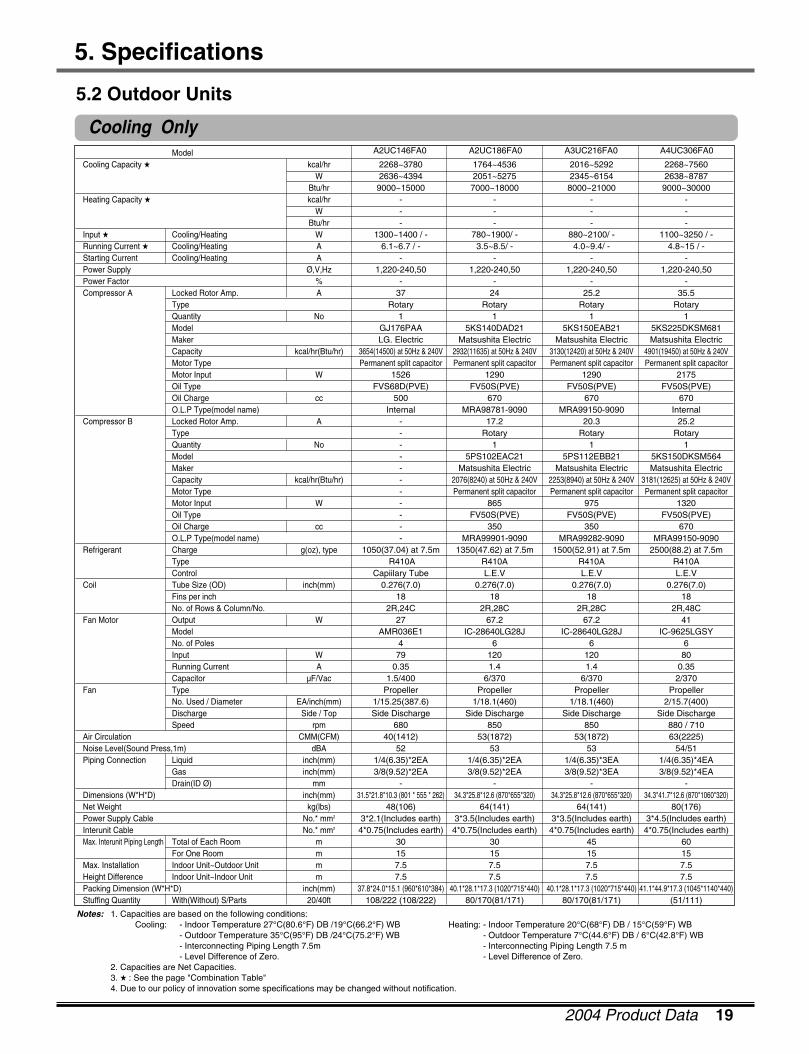
5. Specifications
Notes: 1. Capacities are based on the following conditions:Cooling: - Indoor Temperature 27°C(80.6°F) DB /19°C(66.2°F) WB Heating: - Indoor Temperature 20°C(68°F) DB / 15°C(59°F) WB
- Outdoor Temperature 35°C(95°F) DB /24°C(75.2°F) WB - Outdoor Temperature 7°C(44.6°F) DB / 6°C(42.8°F) WB- Interconnecting Piping Length 7.5m - Interconnecting Piping Length 7.5 m- Level Difference of Zero. - Level Difference of Zero.
2. Capacities are Net Capacities.3. � : See the page "Combination Table"4. Due to our policy of innovation some specifications may be changed without notification.
ModelCooling Capacity � kcal/hr
WBtu/hr
Heating Capacity � kcal/hrW
Btu/hrInput � Cooling/Heating WRunning Current � Cooling/Heating AStarting Current Cooling/Heating APower Supply Ø,V,HzPower Factor %Compressor A Locked Rotor Amp. A
TypeQuantity NoModelMakerCapacity kcal/hr(Btu/hr)Motor TypeMotor Input WOil TypeOil Charge ccO.L.P Type(model name)
Compressor B Locked Rotor Amp. ATypeQuantity NoModelMakerCapacity kcal/hr(Btu/hr)Motor TypeMotor Input WOil TypeOil Charge ccO.L.P Type(model name)
Refrigerant Charge g(oz), typeTypeControl
Coil Tube Size (OD) inch(mm)Fins per inchNo. of Rows & Column/No.
Fan Motor Output WModelNo. of PolesInput WRunning Current ACapacitor µF/Vac
Fan TypeNo. Used / Diameter EA/inch(mm)Discharge Side / TopSpeed rpm
Air Circulation CMM(CFM)Noise Level(Sound Press,1m) dBAPiping Connection Liquid inch(mm)
Gas inch(mm)Drain(ID Ø) mm
Dimensions (W*H*D) inch(mm)Net Weight kg(lbs)Power Supply Cable No.* mm2
Interunit Cable No.* mm2
Max. Interunit Piping Length Total of Each Room mFor One Room m
Max. Installation Indoor Unit~Outdoor Unit mHeight Difference Indoor Unit~Indoor Unit mPacking Dimension (W*H*D) inch(mm)Stuffing Quantity With(Without) S/Parts 20/40ft
2268~3780 1764~4536 2016~5292 2268~75602636~4394 2051~5275 2345~6154 2638~8787
9000~15000 7000~18000 8000~21000 9000~30000- - - -- - - -- - - -
1300~1400 / - 780~1900/ - 880~2100/ - 1100~3250 / -6.1~6.7 / - 3.5~8.5/ - 4.0~9.4/ - 4.8~15 / -
- - - -1,220-240,50 1,220-240,50 1,220-240,50 1,220-240,50
- - - -37 24 25.2 35.5
Rotary Rotary Rotary Rotary1 1 1 1
GJ176PAA 5KS140DAD21 5KS150EAB21 5KS225DKSM681LG. Electric Matsushita Electric Matsushita Electric Matsushita Electric
3654(14500) at 50Hz & 240V 2932(11635) at 50Hz & 240V 3130(12420) at 50Hz & 240V 4901(19450) at 50Hz & 240VPermanent split capacitor Permanent split capacitor Permanent split capacitor Permanent split capacitor
1526 1290 1290 2175FVS68D(PVE) FV50S(PVE) FV50S(PVE) FV50S(PVE)
500 670 670 670Internal MRA98781-9090 MRA99150-9090 Internal
- 17.2 20.3 25.2- Rotary Rotary Rotary- 1 1 1- 5PS102EAC21 5PS112EBB21 5KS150DKSM564- Matsushita Electric Matsushita Electric Matsushita Electric- 2076(8240) at 50Hz & 240V 2253(8940) at 50Hz & 240V 3181(12625) at 50Hz & 240V- Permanent split capacitor Permanent split capacitor Permanent split capacitor- 865 975 1320- FV50S(PVE) FV50S(PVE) FV50S(PVE)- 350 350 670- MRA99901-9090 MRA99282-9090 MRA99150-9090
1050(37.04) at 7.5m 1350(47.62) at 7.5m 1500(52.91) at 7.5m 2500(88.2) at 7.5mR410A R410A R410A R410A
Capiilary Tube L.E.V L.E.V L.E.V0.276(7.0) 0.276(7.0) 0.276(7.0) 0.276(7.0)
18 18 18 182R,24C 2R,28C 2R,28C 2R,48C
27 67.2 67.2 41AMR036E1 IC-28640LG28J IC-28640LG28J IC-9625LGSY
4 6 6 679 120 120 80
0.35 1.4 1.4 0.351.5/400 6/370 6/370 2/370
Propeller Propeller Propeller Propeller1/15.25(387.6) 1/18.1(460) 1/18.1(460) 2/15.7(400)Side Discharge Side Discharge Side Discharge Side Discharge
680 850 850 880 / 71040(1412) 53(1872) 53(1872) 63(2225)
52 53 53 54/511/4(6.35)*2EA 1/4(6.35)*2EA 1/4(6.35)*3EA 1/4(6.35)*4EA3/8(9.52)*2EA 3/8(9.52)*2EA 3/8(9.52)*3EA 3/8(9.52)*4EA
- - - -31.5*21.8*10.3 (801 * 555 * 262) 34.3*25.8*12.6 (870*655*320) 34.3*25.8*12.6 (870*655*320) 34.3*41.7*12.6 (870*1060*320)
48(106) 64(141) 64(141) 80(176)3*2.1(Includes earth) 3*3.5(Includes earth) 3*3.5(Includes earth) 3*4.5(Includes earth)4*0.75(Includes earth) 4*0.75(Includes earth) 4*0.75(Includes earth) 4*0.75(Includes earth)
30 30 45 6015 15 15 157.5 7.5 7.5 7.57.5 7.5 7.5 7.5
37.8*24.0*15.1 (960*610*384) 40.1*28.1*17.3 (1020*715*440) 40.1*28.1*17.3 (1020*715*440) 41.1*44.9*17.3 (1045*1140*440)108/222 (108/222) 80/170(81/171) 80/170(81/171) (51/111)
5.2 Outdoor Units
A2UC146FA0 A2UC186FA0 A3UC216FA0 A4UC306FA0
Cooling Only
20 MPS Variable Multi Split System(50Hz, R410A)
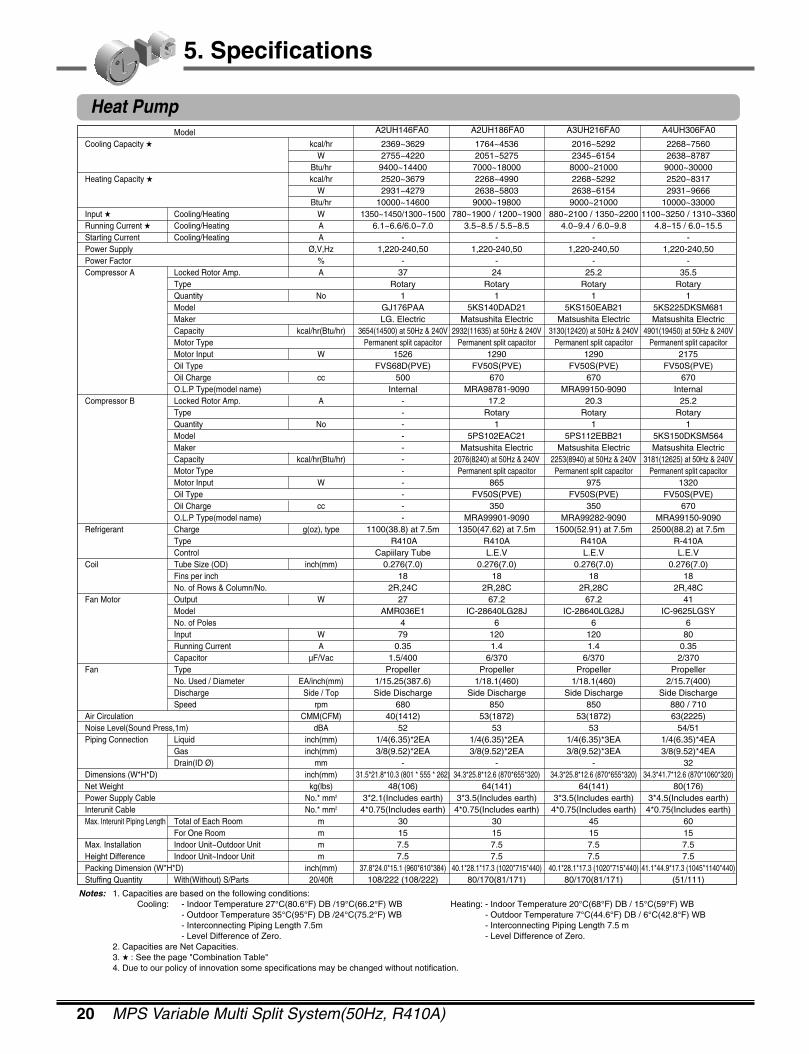
5. Specifications
Notes: 1. Capacities are based on the following conditions:Cooling: - Indoor Temperature 27°C(80.6°F) DB /19°C(66.2°F) WB Heating: - Indoor Temperature 20°C(68°F) DB / 15°C(59°F) WB
- Outdoor Temperature 35°C(95°F) DB /24°C(75.2°F) WB - Outdoor Temperature 7°C(44.6°F) DB / 6°C(42.8°F) WB- Interconnecting Piping Length 7.5m - Interconnecting Piping Length 7.5 m- Level Difference of Zero. - Level Difference of Zero.
2. Capacities are Net Capacities.3. � : See the page "Combination Table"4. Due to our policy of innovation some specifications may be changed without notification.
ModelCooling Capacity � kcal/hr
WBtu/hr
Heating Capacity � kcal/hrW
Btu/hrInput � Cooling/Heating WRunning Current � Cooling/Heating AStarting Current Cooling/Heating APower Supply Ø,V,HzPower Factor %Compressor A Locked Rotor Amp. A
TypeQuantity NoModelMakerCapacity kcal/hr(Btu/hr)Motor TypeMotor Input WOil TypeOil Charge ccO.L.P Type(model name)
Compressor B Locked Rotor Amp. ATypeQuantity NoModelMakerCapacity kcal/hr(Btu/hr)Motor TypeMotor Input WOil TypeOil Charge ccO.L.P Type(model name)
Refrigerant Charge g(oz), typeTypeControl
Coil Tube Size (OD) inch(mm)Fins per inchNo. of Rows & Column/No.
Fan Motor Output WModelNo. of PolesInput WRunning Current ACapacitor µF/Vac
Fan TypeNo. Used / Diameter EA/inch(mm)Discharge Side / TopSpeed rpm
Air Circulation CMM(CFM)Noise Level(Sound Press,1m) dBAPiping Connection Liquid inch(mm)
Gas inch(mm)Drain(ID Ø) mm
Dimensions (W*H*D) inch(mm)Net Weight kg(lbs)Power Supply Cable No.* mm2
Interunit Cable No.* mm2
Max. Interunit Piping Length Total of Each Room mFor One Room m
Max. Installation Indoor Unit~Outdoor Unit mHeight Difference Indoor Unit~Indoor Unit mPacking Dimension (W*H*D) inch(mm)Stuffing Quantity With(Without) S/Parts 20/40ft
2369~3629 1764~4536 2016~5292 2268~75602755~4220 2051~5275 2345~6154 2638~87879400~14400 7000~18000 8000~21000 9000~300002520~3679 2268~4990 2268~5292 2520~83172931~4279 2638~5803 2638~6154 2931~9666
10000~14600 9000~19800 9000~21000 10000~330001350~1450/1300~1500 780~1900 / 1200~1900 880~2100 / 1350~2200 1100~3250 / 1310~3360
6.1~6.6/6.0~7.0 3.5~8.5 / 5.5~8.5 4.0~9.4 / 6.0~9.8 4.8~15 / 6.0~15.5- - - -
1,220-240,50 1,220-240,50 1,220-240,50 1,220-240,50- - - -
37 24 25.2 35.5Rotary Rotary Rotary Rotary
1 1 1 1GJ176PAA 5KS140DAD21 5KS150EAB21 5KS225DKSM681LG. Electric Matsushita Electric Matsushita Electric Matsushita Electric
3654(14500) at 50Hz & 240V 2932(11635) at 50Hz & 240V 3130(12420) at 50Hz & 240V 4901(19450) at 50Hz & 240VPermanent split capacitor Permanent split capacitor Permanent split capacitor Permanent split capacitor
1526 1290 1290 2175FVS68D(PVE) FV50S(PVE) FV50S(PVE) FV50S(PVE)
500 670 670 670Internal MRA98781-9090 MRA99150-9090 Internal
- 17.2 20.3 25.2- Rotary Rotary Rotary- 1 1 1- 5PS102EAC21 5PS112EBB21 5KS150DKSM564- Matsushita Electric Matsushita Electric Matsushita Electric- 2076(8240) at 50Hz & 240V 2253(8940) at 50Hz & 240V 3181(12625) at 50Hz & 240V- Permanent split capacitor Permanent split capacitor Permanent split capacitor- 865 975 1320- FV50S(PVE) FV50S(PVE) FV50S(PVE)- 350 350 670- MRA99901-9090 MRA99282-9090 MRA99150-9090
1100(38.8) at 7.5m 1350(47.62) at 7.5m 1500(52.91) at 7.5m 2500(88.2) at 7.5mR410A R410A R410A R-410A
Capiilary Tube L.E.V L.E.V L.E.V0.276(7.0) 0.276(7.0) 0.276(7.0) 0.276(7.0)
18 18 18 182R,24C 2R,28C 2R,28C 2R,48C
27 67.2 67.2 41AMR036E1 IC-28640LG28J IC-28640LG28J IC-9625LGSY
4 6 6 679 120 120 80
0.35 1.4 1.4 0.351.5/400 6/370 6/370 2/370
Propeller Propeller Propeller Propeller1/15.25(387.6) 1/18.1(460) 1/18.1(460) 2/15.7(400)Side Discharge Side Discharge Side Discharge Side Discharge
680 850 850 880 / 71040(1412) 53(1872) 53(1872) 63(2225)
52 53 53 54/511/4(6.35)*2EA 1/4(6.35)*2EA 1/4(6.35)*3EA 1/4(6.35)*4EA3/8(9.52)*2EA 3/8(9.52)*2EA 3/8(9.52)*3EA 3/8(9.52)*4EA
- - - 3231.5*21.8*10.3 (801 * 555 * 262) 34.3*25.8*12.6 (870*655*320) 34.3*25.8*12.6 (870*655*320) 34.3*41.7*12.6 (870*1060*320)
48(106) 64(141) 64(141) 80(176)3*2.1(Includes earth) 3*3.5(Includes earth) 3*3.5(Includes earth) 3*4.5(Includes earth)
4*0.75(Includes earth) 4*0.75(Includes earth) 4*0.75(Includes earth) 4*0.75(Includes earth)30 30 45 6015 15 15 157.5 7.5 7.5 7.57.5 7.5 7.5 7.5
37.8*24.0*15.1 (960*610*384) 40.1*28.1*17.3 (1020*715*440) 40.1*28.1*17.3 (1020*715*440) 41.1*44.9*17.3 (1045*1140*440)108/222 (108/222) 80/170(81/171) 80/170(81/171) (51/111)
A2UH146FA0 A2UH186FA0 A3UH216FA0 A4UH306FA0
Heat Pump
2004 Product Data 21
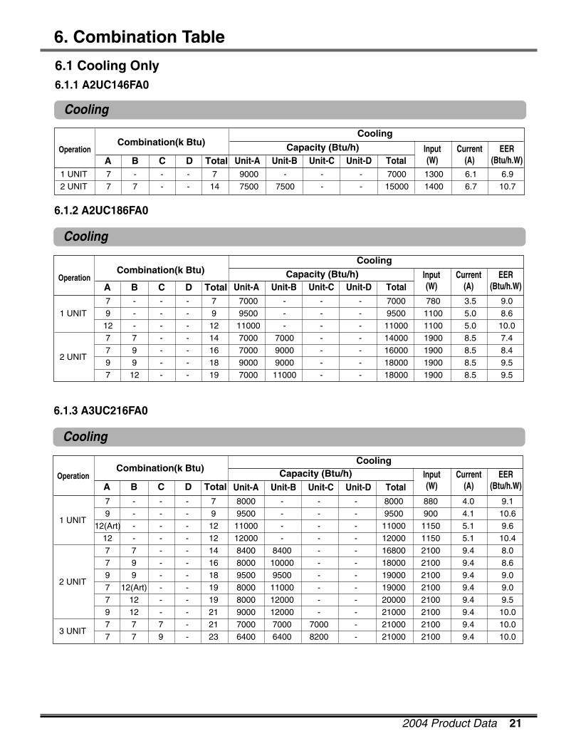
6. Combination Table
Cooling
6.1 Cooling Only6.1.1 A2UC146FA0
Combination(k Btu) Capacity (Btu/h)Cooling
Input(W)
Current(A)
EER(Btu/h.W)A B C D Total
Operation
1 UNIT 7 - - - 7 9000 - - - 7000 1300 6.1 6.92 UNIT 7 7 - - 14 7500 7500 - - 15000 1400 6.7 10.7
Cooling
6.1.2 A2UC186FA0
Combination(k Btu) Capacity (Btu/h)Cooling
Unit-A Unit-B Unit-C Unit-D TotalInput(W)
Current(A)
EER(Btu/h.W)A B C D Total
Operation
7 - - - 7 7000 - - - 7000 780 3.5 9.0 1 UNIT 9 - - - 9 9500 - - - 9500 1100 5.0 8.6
12 - - - 12 11000 - - - 11000 1100 5.0 10.0 7 7 - - 14 7000 7000 - - 14000 1900 8.5 7.4
2 UNIT7 9 - - 16 7000 9000 - - 16000 1900 8.5 8.4 9 9 - - 18 9000 9000 - - 18000 1900 8.5 9.5 7 12 - - 19 7000 11000 - - 18000 1900 8.5 9.5
Cooling
6.1.3 A3UC216FA0
Combination(k Btu) Capacity (Btu/h)Cooling
Unit-A Unit-B Unit-C Unit-D TotalInput(W)
Current(A)
EER(Btu/h.W)A B C D Total
Operation
7 - - - 7 8000 - - - 8000 880 4.0 9.1
1 UNIT9 - - - 9 9500 - - - 9500 900 4.1 10.6
12(Art) - - - 12 11000 - - - 11000 1150 5.1 9.6 12 - - - 12 12000 - - - 12000 1150 5.1 10.4 7 7 - - 14 8400 8400 - - 16800 2100 9.4 8.0 7 9 - - 16 8000 10000 - - 18000 2100 9.4 8.6
2 UNIT9 9 - - 18 9500 9500 - - 19000 2100 9.4 9.0 7 12(Art) - - 19 8000 11000 - - 19000 2100 9.4 9.0 7 12 - - 19 8000 12000 - - 20000 2100 9.4 9.5 9 12 - - 21 9000 12000 - - 21000 2100 9.4 10.0
3 UNIT7 7 7 - 21 7000 7000 7000 - 21000 2100 9.4 10.0 7 7 9 - 23 6400 6400 8200 - 21000 2100 9.4 10.0
Unit-A Unit-B Unit-C Unit-D Total
Cooling
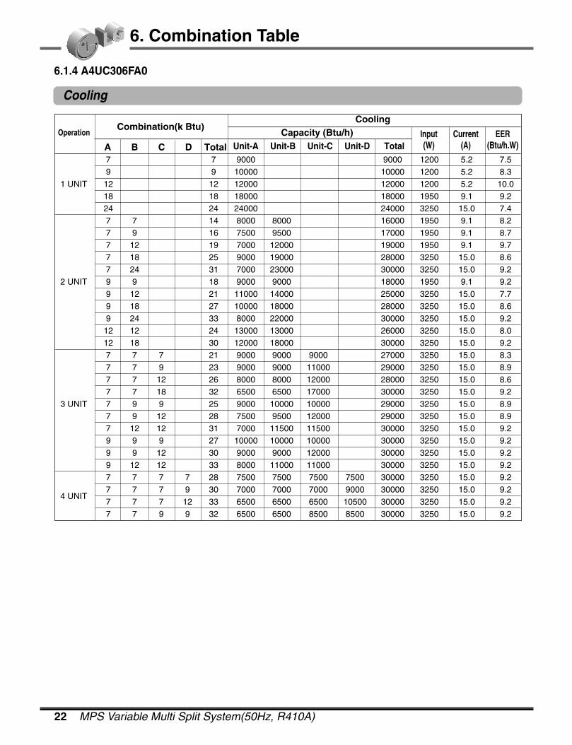
6.1.4 A4UC306FA0
22 MPS Variable Multi Split System(50Hz, R410A)
6. Combination Table
Combination(k Btu)Capacity (Btu/h)
Cooling
Unit-A Unit-B Unit-C Unit-D TotalInput(W)
Current(A)
EER(Btu/h.W)A B C D Total
Operation
7 7 9000 9000 1200 5.2 7.5 9 9 10000 10000 1200 5.2 8.3
1 UNIT 12 12 12000 12000 1200 5.2 10.0 18 18 18000 18000 1950 9.1 9.2 24 24 24000 24000 3250 15.0 7.4 7 7 14 8000 8000 16000 1950 9.1 8.2 7 9 16 7500 9500 17000 1950 9.1 8.7 7 12 19 7000 12000 19000 1950 9.1 9.7 7 18 25 9000 19000 28000 3250 15.0 8.6 7 24 31 7000 23000 30000 3250 15.0 9.2
2 UNIT 9 9 18 9000 9000 18000 1950 9.1 9.2 9 12 21 11000 14000 25000 3250 15.0 7.7 9 18 27 10000 18000 28000 3250 15.0 8.6 9 24 33 8000 22000 30000 3250 15.0 9.2 12 12 24 13000 13000 26000 3250 15.0 8.0 12 18 30 12000 18000 30000 3250 15.0 9.2 7 7 7 21 9000 9000 9000 27000 3250 15.0 8.3 7 7 9 23 9000 9000 11000 29000 3250 15.0 8.9 7 7 12 26 8000 8000 12000 28000 3250 15.0 8.6 7 7 18 32 6500 6500 17000 30000 3250 15.0 9.2
3 UNIT 7 9 9 25 9000 10000 10000 29000 3250 15.0 8.9 7 9 12 28 7500 9500 12000 29000 3250 15.0 8.9 7 12 12 31 7000 11500 11500 30000 3250 15.0 9.2 9 9 9 27 10000 10000 10000 30000 3250 15.0 9.2 9 9 12 30 9000 9000 12000 30000 3250 15.0 9.2 9 12 12 33 8000 11000 11000 30000 3250 15.0 9.2 7 7 7 7 28 7500 7500 7500 7500 30000 3250 15.0 9.2
4 UNIT7 7 7 9 30 7000 7000 7000 9000 30000 3250 15.0 9.2 7 7 7 12 33 6500 6500 6500 10500 30000 3250 15.0 9.2 7 7 9 9 32 6500 6500 8500 8500 30000 3250 15.0 9.2
2004 Product Data 23
6. Combination Table
Cooling
Heating
Heating
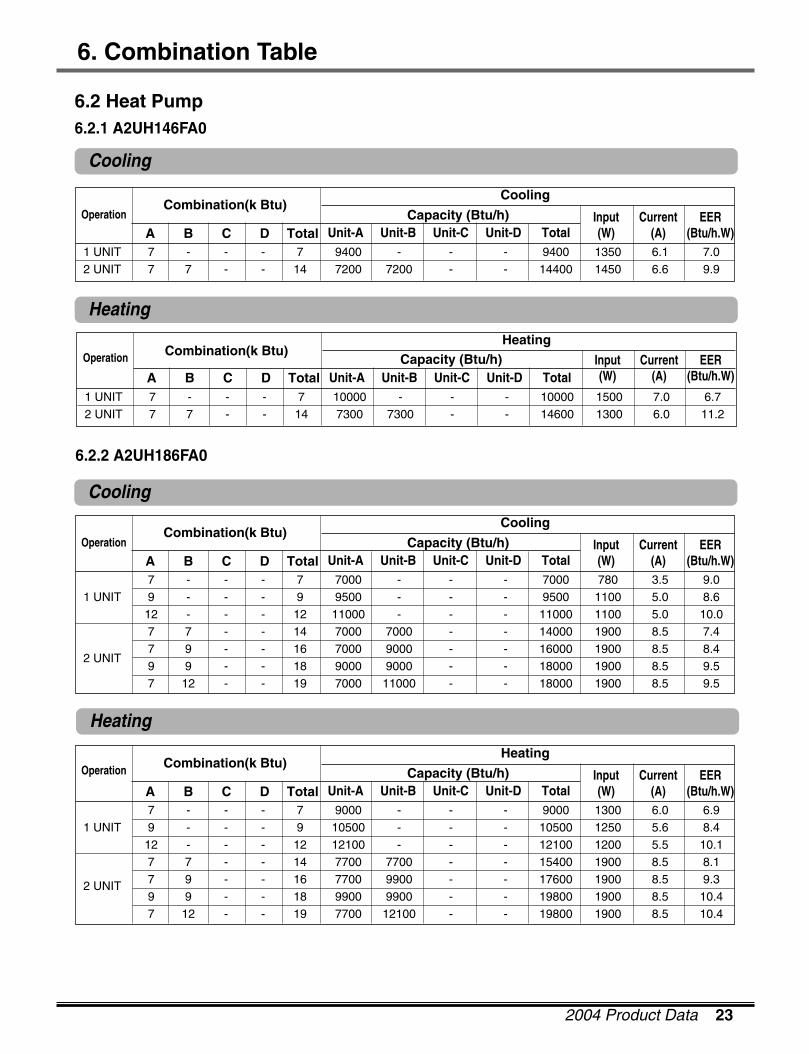
6.2 Heat Pump6.2.1 A2UH146FA0
Combination(k Btu)Capacity (Btu/h)
Cooling
Unit-A Unit-B Unit-C Unit-D TotalInput(W)
Current(A)
EER(Btu/h.W)A B C D Total
Operation
1 UNIT 7 - - - 7 9400 - - - 9400 1350 6.1 7.0 2 UNIT 7 7 - - 14 7200 7200 - - 14400 1450 6.6 9.9
Combination(k Btu)Capacity (Btu/h)
Cooling
Unit-A Unit-B Unit-C Unit-D TotalInput(W)
Current(A)
EER(Btu/h.W)A B C D Total
Operation
7 - - - 7 7000 - - - 7000 780 3.5 9.0 1 UNIT 9 - - - 9 9500 - - - 9500 1100 5.0 8.6
12 - - - 12 11000 - - - 11000 1100 5.0 10.0 7 7 - - 14 7000 7000 - - 14000 1900 8.5 7.4
2 UNIT7 9 - - 16 7000 9000 - - 16000 1900 8.5 8.4 9 9 - - 18 9000 9000 - - 18000 1900 8.5 9.5 7 12 - - 19 7000 11000 - - 18000 1900 8.5 9.5
Combination(k Btu)Capacity (Btu/h)
Heating
Unit-A Unit-B Unit-C Unit-D TotalInput(W)
Current(A)
EER(Btu/h.W)A B C D Total
Operation
7 - - - 7 9000 - - - 9000 1300 6.0 6.9 1 UNIT 9 - - - 9 10500 - - - 10500 1250 5.6 8.4
12 - - - 12 12100 - - - 12100 1200 5.5 10.1 7 7 - - 14 7700 7700 - - 15400 1900 8.5 8.1
2 UNIT 7 9 - - 16 7700 9900 - - 17600 1900 8.5 9.3 9 9 - - 18 9900 9900 - - 19800 1900 8.5 10.4 7 12 - - 19 7700 12100 - - 19800 1900 8.5 10.4
Combination(k Btu)Capacity (Btu/h)
Heating
Unit-A Unit-B Unit-C Unit-D TotalInput(W)
Current(A)
EER(Btu/h.W)A B C D Total
Operation
1 UNIT 7 - - - 7 10000 - - - 10000 1500 7.0 6.7 2 UNIT 7 7 - - 14 7300 7300 - - 14600 1300 6.0 11.2
Cooling
6.2.2 A2UH186FA0
24 MPS Variable Multi Split System(50Hz, R410A)
6. Combination Table
Cooling
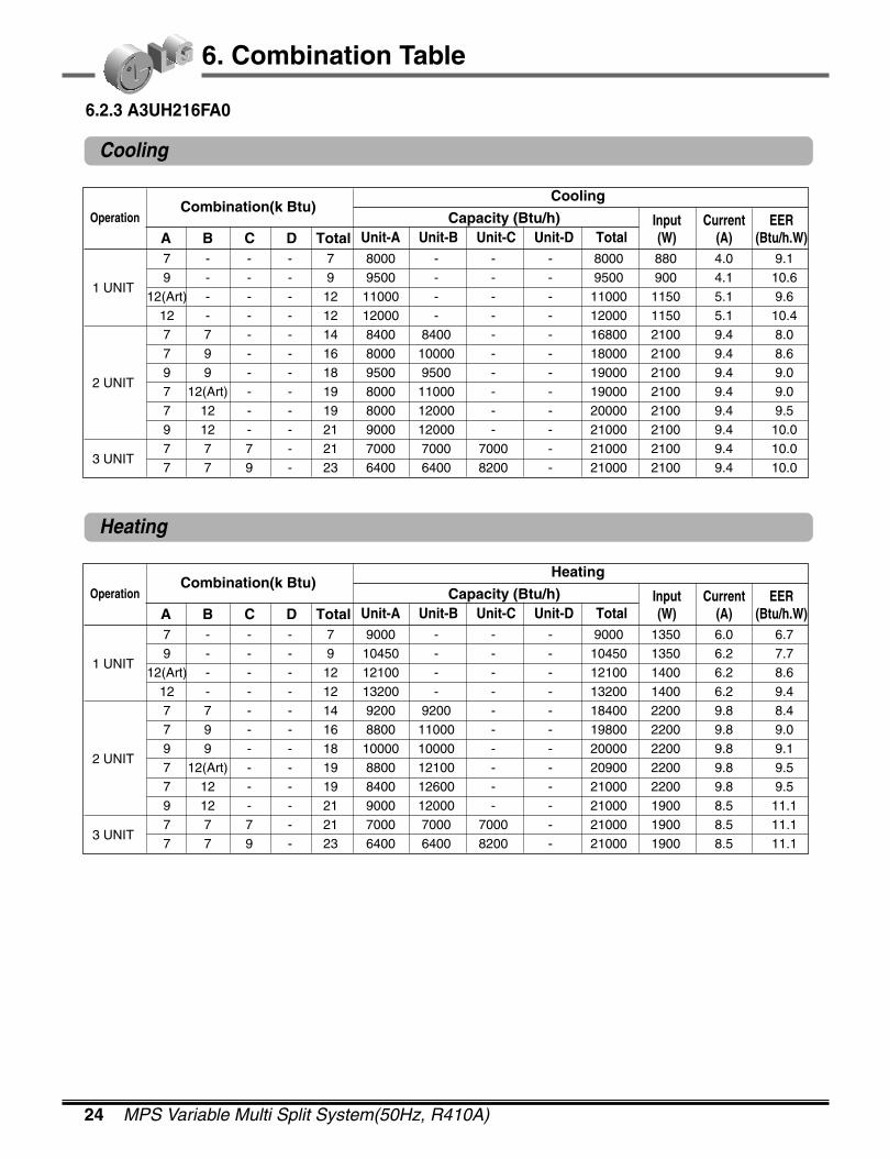
6.2.3 A3UH216FA0
Heating
Combination(k Btu)Capacity (Btu/h)
Cooling
Unit-A Unit-B Unit-C Unit-D TotalInput(W)
Current(A)
EER(Btu/h.W)A B C D Total
Operation
7 - - - 7 8000 - - - 8000 880 4.0 9.1
1 UNIT9 - - - 9 9500 - - - 9500 900 4.1 10.6
12(Art) - - - 12 11000 - - - 11000 1150 5.1 9.6 12 - - - 12 12000 - - - 12000 1150 5.1 10.4 7 7 - - 14 8400 8400 - - 16800 2100 9.4 8.0 7 9 - - 16 8000 10000 - - 18000 2100 9.4 8.6
2 UNIT9 9 - - 18 9500 9500 - - 19000 2100 9.4 9.0 7 12(Art) - - 19 8000 11000 - - 19000 2100 9.4 9.0 7 12 - - 19 8000 12000 - - 20000 2100 9.4 9.5 9 12 - - 21 9000 12000 - - 21000 2100 9.4 10.0
3 UNIT7 7 7 - 21 7000 7000 7000 - 21000 2100 9.4 10.0 7 7 9 - 23 6400 6400 8200 - 21000 2100 9.4 10.0
Combination(k Btu)Capacity (Btu/h)
Heating
Unit-A Unit-B Unit-C Unit-D TotalInput(W)
Current(A)
EER(Btu/h.W)A B C D Total
Operation
7 - - - 7 9000 - - - 9000 1350 6.0 6.7
1 UNIT9 - - - 9 10450 - - - 10450 1350 6.2 7.7
12(Art) - - - 12 12100 - - - 12100 1400 6.2 8.6 12 - - - 12 13200 - - - 13200 1400 6.2 9.4 7 7 - - 14 9200 9200 - - 18400 2200 9.8 8.4 7 9 - - 16 8800 11000 - - 19800 2200 9.8 9.0
2 UNIT9 9 - - 18 10000 10000 - - 20000 2200 9.8 9.1 7 12(Art) - - 19 8800 12100 - - 20900 2200 9.8 9.5 7 12 - - 19 8400 12600 - - 21000 2200 9.8 9.5 9 12 - - 21 9000 12000 - - 21000 1900 8.5 11.1
3 UNIT7 7 7 - 21 7000 7000 7000 - 21000 1900 8.5 11.1 7 7 9 - 23 6400 6400 8200 - 21000 1900 8.5 11.1
2004 Product Data 25
6. Combination Table
Cooling
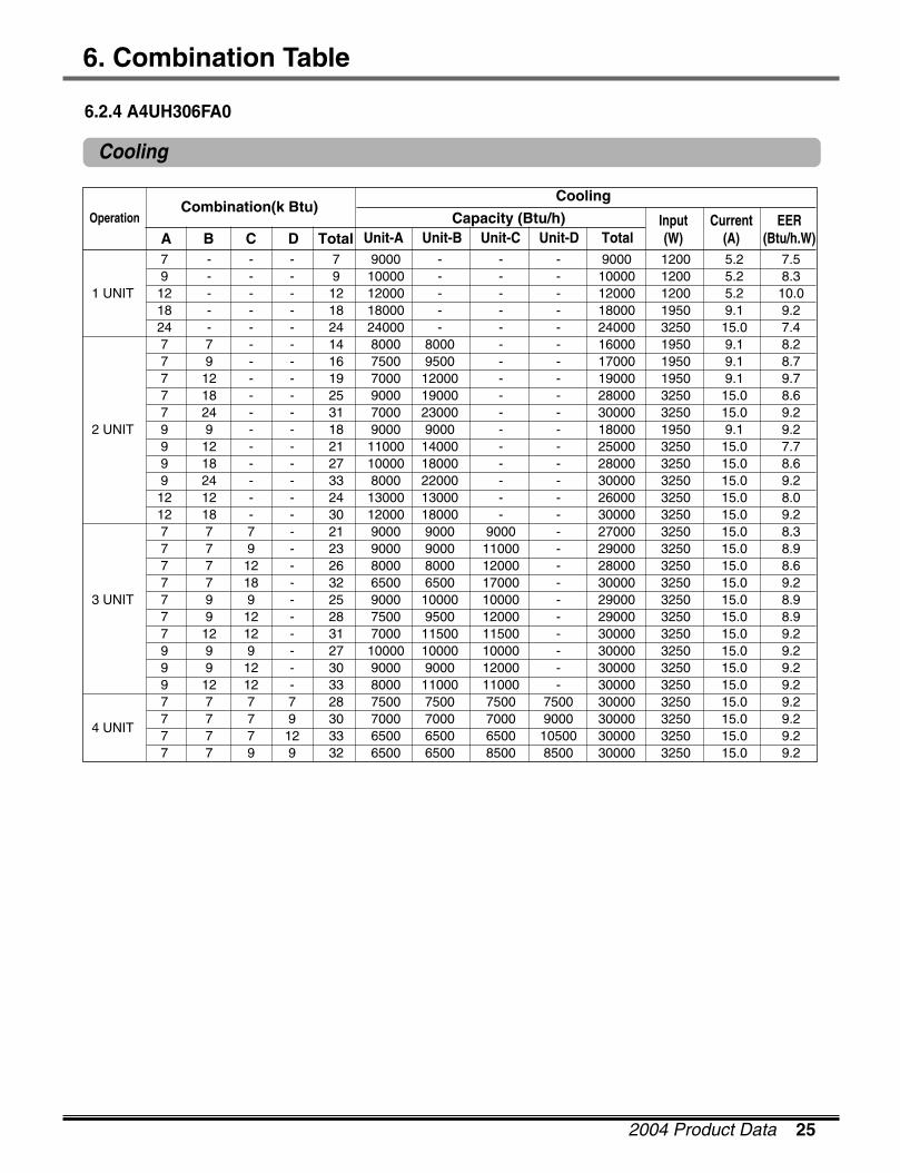
6.2.4 A4UH306FA0
Combination(k Btu)Capacity (Btu/h)
Cooling
Unit-A Unit-B Unit-C Unit-D TotalInput(W)
Current(A)
EER(Btu/h.W)A B C D Total
Operation
7 - - - 7 9000 - - - 9000 1200 5.2 7.5 9 - - - 9 10000 - - - 10000 1200 5.2 8.3
1 UNIT 12 - - - 12 12000 - - - 12000 1200 5.2 10.0 18 - - - 18 18000 - - - 18000 1950 9.1 9.2 24 - - - 24 24000 - - - 24000 3250 15.0 7.4 7 7 - - 14 8000 8000 - - 16000 1950 9.1 8.2 7 9 - - 16 7500 9500 - - 17000 1950 9.1 8.7 7 12 - - 19 7000 12000 - - 19000 1950 9.1 9.7 7 18 - - 25 9000 19000 - - 28000 3250 15.0 8.6 7 24 - - 31 7000 23000 - - 30000 3250 15.0 9.2
2 UNIT 9 9 - - 18 9000 9000 - - 18000 1950 9.1 9.2 9 12 - - 21 11000 14000 - - 25000 3250 15.0 7.7 9 18 - - 27 10000 18000 - - 28000 3250 15.0 8.6 9 24 - - 33 8000 22000 - - 30000 3250 15.0 9.2 12 12 - - 24 13000 13000 - - 26000 3250 15.0 8.0 12 18 - - 30 12000 18000 - - 30000 3250 15.0 9.2 7 7 7 - 21 9000 9000 9000 - 27000 3250 15.0 8.3 7 7 9 - 23 9000 9000 11000 - 29000 3250 15.0 8.9 7 7 12 - 26 8000 8000 12000 - 28000 3250 15.0 8.6 7 7 18 - 32 6500 6500 17000 - 30000 3250 15.0 9.2
3 UNIT 7 9 9 - 25 9000 10000 10000 - 29000 3250 15.0 8.9 7 9 12 - 28 7500 9500 12000 - 29000 3250 15.0 8.9 7 12 12 - 31 7000 11500 11500 - 30000 3250 15.0 9.2 9 9 9 - 27 10000 10000 10000 - 30000 3250 15.0 9.2 9 9 12 - 30 9000 9000 12000 - 30000 3250 15.0 9.2 9 12 12 - 33 8000 11000 11000 - 30000 3250 15.0 9.2 7 7 7 7 28 7500 7500 7500 7500 30000 3250 15.0 9.2
4 UNIT7 7 7 9 30 7000 7000 7000 9000 30000 3250 15.0 9.2 7 7 7 12 33 6500 6500 6500 10500 30000 3250 15.0 9.2 7 7 9 9 32 6500 6500 8500 8500 30000 3250 15.0 9.2
26 MPS Variable Multi Split System(50Hz, R410A)
6. Combination Table
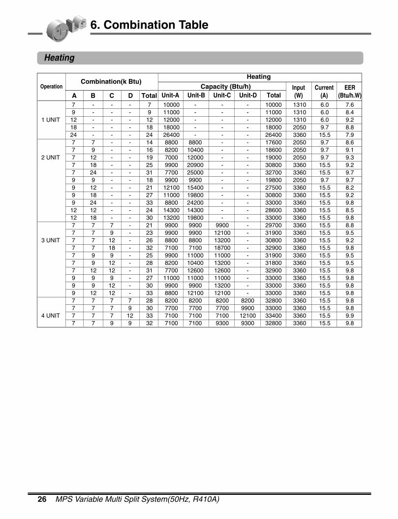
Heating
Combination(k Btu)Capacity (Btu/h)
Heating
Unit-A Unit-B Unit-C Unit-D TotalInput(W)
Current(A)
EER(Btu/h.W)A B C D Total
Operation
7 - - - 7 10000 - - - 10000 1310 6.0 7.69 - - - 9 11000 - - - 11000 1310 6.0 8.4
1 UNIT 12 - - - 12 12000 - - - 12000 1310 6.0 9.218 - - - 18 18000 - - - 18000 2050 9.7 8.824 - - - 24 26400 - - - 26400 3360 15.5 7.97 7 - - 14 8800 8800 - - 17600 2050 9.7 8.67 9 - - 16 8200 10400 - - 18600 2050 9.7 9.1
2 UNIT 7 12 - - 19 7000 12000 - - 19000 2050 9.7 9.37 18 - - 25 9900 20900 - - 30800 3360 15.5 9.27 24 - - 31 7700 25000 - - 32700 3360 15.5 9.79 9 - - 18 9900 9900 - - 19800 2050 9.7 9.79 12 - - 21 12100 15400 - - 27500 3360 15.5 8.29 18 - - 27 11000 19800 - - 30800 3360 15.5 9.29 24 - - 33 8800 24200 - - 33000 3360 15.5 9.812 12 - - 24 14300 14300 - - 28600 3360 15.5 8.512 18 - - 30 13200 19800 - - 33000 3360 15.5 9.87 7 7 - 21 9900 9900 9900 - 29700 3360 15.5 8.87 7 9 - 23 9900 9900 12100 - 31900 3360 15.5 9.5
3 UNIT 7 7 12 - 26 8800 8800 13200 - 30800 3360 15.5 9.27 7 18 - 32 7100 7100 18700 - 32900 3360 15.5 9.87 9 9 - 25 9900 11000 11000 - 31900 3360 15.5 9.57 9 12 - 28 8200 10400 13200 - 31800 3360 15.5 9.57 12 12 - 31 7700 12600 12600 - 32900 3360 15.5 9.89 9 9 - 27 11000 11000 11000 - 33000 3360 15.5 9.89 9 12 - 30 9900 9900 13200 - 33000 3360 15.5 9.89 12 12 - 33 8800 12100 12100 - 33000 3360 15.5 9.87 7 7 7 28 8200 8200 8200 8200 32800 3360 15.5 9.87 7 7 9 30 7700 7700 7700 9900 33000 3360 15.5 9.8
4 UNIT 7 7 7 12 33 7100 7100 7100 12100 33400 3360 15.5 9.97 7 9 9 32 7100 7100 9300 9300 32800 3360 15.5 9.8
2004 Product Data 27
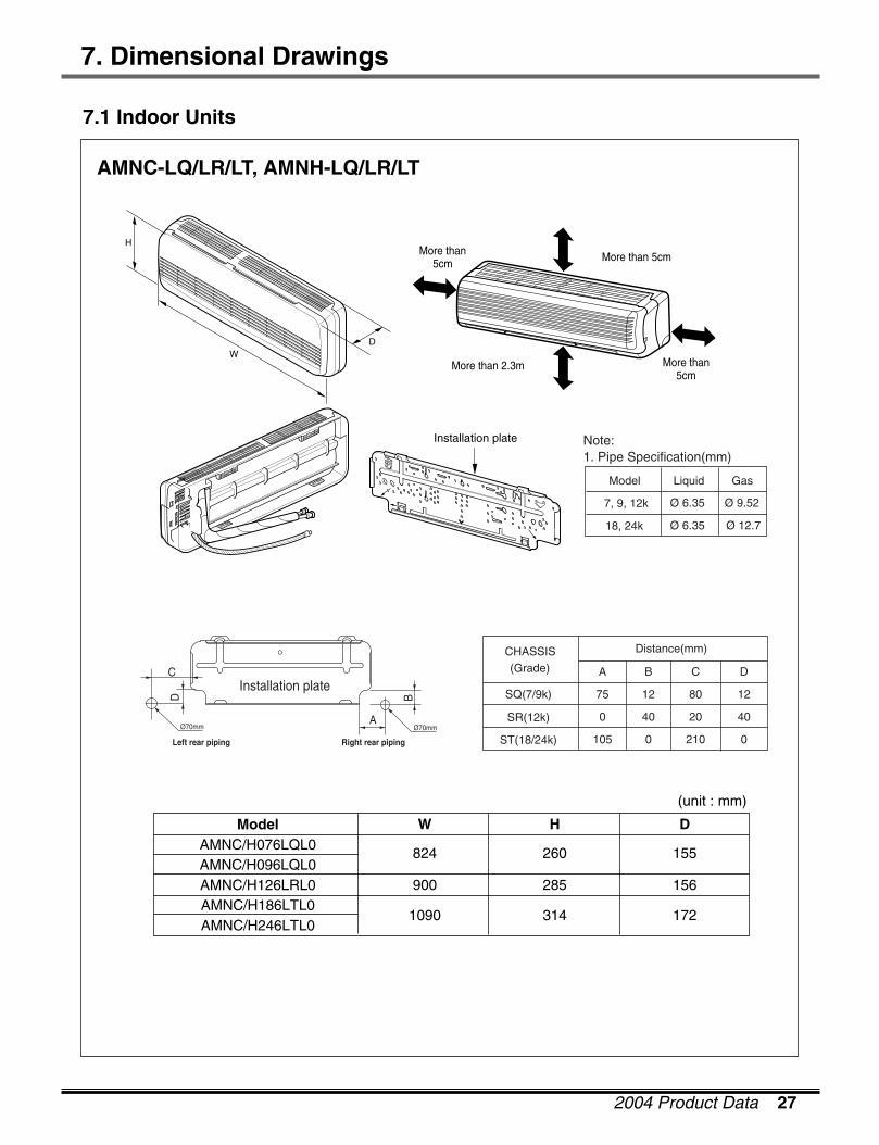
7. Dimensional Drawings
AMNC-LQ/LR/LT, AMNH-LQ/LR/LT
W
824
900
1090
H
260
285
314
D
155
156
172
ModelAMNC/H076LQL0AMNC/H096LQL0AMNC/H126LRL0AMNC/H186LTL0AMNC/H246LTL0
(unit : mm)
7.1 Indoor Units
Installation plate
D
H
W
More than 5cmMore than5cm
More than 2.3m More than5cm
Ø 12.7Ø 6.3518, 24k
Ø 9.52Ø 6.357, 9, 12k
GasLiquidModel
1. Pipe Specification(mm)Note:
4020400SR(12k)
0
12
D
0
12
B CA
210105ST(18/24k)
8075SQ(7/9k)
Distance(mm)CHASSIS(Grade)
Installation plate
Ø70mm
Left rear piping Right rear piping
C
D B
AØ70mm

28 MPS Variable Multi Split System(50Hz, R410A)
W
570
H
568
D
129
ModelAMNC/H096AP*1AMNC/H126AP*1
(unit : mm)
7. Dimensional Drawings
Ø 9.52Ø 6.359, 12k
GasLiquidModel
1. Pipe Specification(mm)Note:
(Unit: mm)
Pipe Hole Fix Hole
Hanger Hole
H
W D
More than 10cm
More than 50cm
More than 2m
More than 50cm
AMNC-AP, AMNH-AP

2004 Product Data 29
7. Dimensional Drawings
A2UC146FA0, A2UH146FA0
7.2 Outdoor Units
W
L6L7 L8 L9
L4
H
D L1L2
L3
L5
L10
Gas side3-way valve
Liquid side2-way valve
L13
L12
L11
W mm 801
H mm 555
D mm 262
L1 mm 339
L2 mm 300
L3 mm 37
L4 mm 543.6
L5 mm 11.4
L6 mm 591
L7 mm 105
L8 mm 105
L9 mm 72.5
L10 mm 74.5
L11 mm 79
A2UC146FA0, A2UH146FA0Model
Dimensions

30 MPS Variable Multi Split System(50Hz, R410A)
7. Dimensional Drawings
A2UC186FA0, A2UH186FA0
W
D L1
L2
L9
L4L3
H
L10
L10
L10
L8
Gas side3-Way valve
Liquid side2-Way valve
L7L5L6
W mm 870
H mm 655
D mm 320
L1 mm 370
L2 mm 25
L3 mm 630
L4 mm 25
L5 mm 546
L6 mm 160
L7 mm 160
L8 mm 64
L9 mm 76.5
L10 mm 50
A2UC186FA0, A2UH186FA0Model
Dimensions

2004 Product Data 31
7. Dimensional Drawings
A3UC216FA0, A3UH216FA0
W
L5L6 L7 L8
L3
H
D L1
L2
L4
L10
L9
Gas side3-way valve
Liquid side2-way valve
L10
L10
L10
L10
W mm 870
H mm 655
D mm 320
L1 mm 370
L2 mm 25
L3 mm 630
L4 mm 25
L5 mm 546
L6 mm 160
L7 mm 160
L8 mm 64
L9 mm 76.5
L10 mm 50
A3UC216FA0, A3UH216FA0Model
Dimensions

32 MPS Variable Multi Split System(50Hz, R410A)
7. Dimensional Drawings
A4UC306FA0, A4UH306FA0
76.5
4-holes for anchor bolts
5050
5050
5050
32064160160 550
1060
360
340
320
1030
870
4
23
1
Number Name Descripition
1 Liquid side service valve(mm) Ø6.35
2 Gas side service valve(mm) Ø9.52
3 Air discharge grill
4 Control Cover

2004 Product Data 33
8. Wiring Diagrams
3854A20135W
CN
-TH
1
THERMISTOR(OUT-PIPE)
THERMISTOR(IN-PIPE)
THERMISTOR(ROOM)
CN
-TH
2C
N-U
/D
CN
-MO
TOR
CN
-PO
WE
R
AC PCB ASM DC PCB ASM
FUSE250V 2A
ZNR
8.1 Indoor Unit
Wall Mounted
CONNECTOR NUMBER Location
CN-POWER AC POWER SUPPLY
CN-MOTOR AC FAN MOTOR OUTPUT
CN-ACDC AC/DC CONNECTION
CN-COMM COMMUNICATION
CN-DISP DISPLAY
CN-DISP2 DISPLAY
CN-UD STEP MOTOR
CN-LR STEP MOTOR
CN-TH1 ROOM/PIPE SENSOR
CN-TH2 DISCHARGE PIPE SENSOR

34 MPS Variable Multi Split System(50Hz, R410A)
8. Wiring Diagrams
ART COOL Type
CONNECT PCB ASM
DISPLAYPCB ASM
AC PWB ASM DC PWB ASM
CN-U
D(BL
)CN
-LR1
(WH)
CN-L
R2(W
H)
PLASMAAIR CLEAN
CN-D1(WH) CN-D2(WH)
BKRD
STEPMOTOR
STEPMOTOR
STEPMOTOR
STEPMOTOR
FORCE S/W
SAFETY S/W
SAFETY S/W
3854A20135Y
CN
-GN
D1
CN
-AC
DC
1
CN
-AC
DC
2
CN-H
VB(B
L)
H.V.ASM
CN
-MO
TO
R1
BK
WH
YLRD
FANMOTOR
CN
-PO
WE
R FUSE 250V 3.15A
ZNR
TO OUTDOOR UNIT
BR
BL
GN/
YL
RD
1(L) 2(N) 3 4
Z
CN
-TH
1
THERMISTOR(OUT-PIPE)
THERMISTOR(IN-PIPE)
THERMISTOR(ROOM)
CN
-TH
2
CONNECTOR NUMBER LOCATION
CN-POWER AC POWER SUPPLY
CN-MOTOR BLDC FAN MOTOR OUTPUT
CN-D1 DISPLAY
CN-D2 DISPLAY
CN-LR1 STEP MOTOR
CN-LR2 STEP MOTOR
CN-UD STEP MOTOR
CN-TH1 ROOM/PIPE SENSOR
CN-TH2 DISCHARGE PIPE SENSOR

2004 Product Data 35
8. Wiring Diagrams
A2UC146FA0
8.2 Outdoor Unit
Notes:
BL BLUE BK BLACK BR BROWNRD RED OR ORANGE WH WHITEYL YELLOW GN/YL GREEN/YELLOW CN CONNECTOR
1(L)
2(N)
1(L)
2(N)
3(A)
3(B)
OUTDOOR WIRING DIAGRAM
MAINPOWER
AS/V
CM
FMo
P/NO : 3854A20375B
BS/V
B/PS/V
MAIN PCB ASSY
BK
BK
BK
BR
BK
BK
T/B1
RD
Co
BL
BL
YL
RD
C
S H C F
R
BKBK
BK
BK
BK
BL
RDRD
T/B2
(RD)(BL)
(BK)
BL
BK
WH
FUSE 250VT3.15A
BL
BRWH
TO IN
DO
OR
UN
IT
CN
-CO
M
(WH
)C
N-C
OM
CN
-CO
MP
(WH
)C
N-H
,L,S,4
(WH
)C
N-P
OW
ER(W
H)
A-UNIT
B-UNIT
(RD
)
36 MPS Variable Multi Split System(50Hz, R410A)
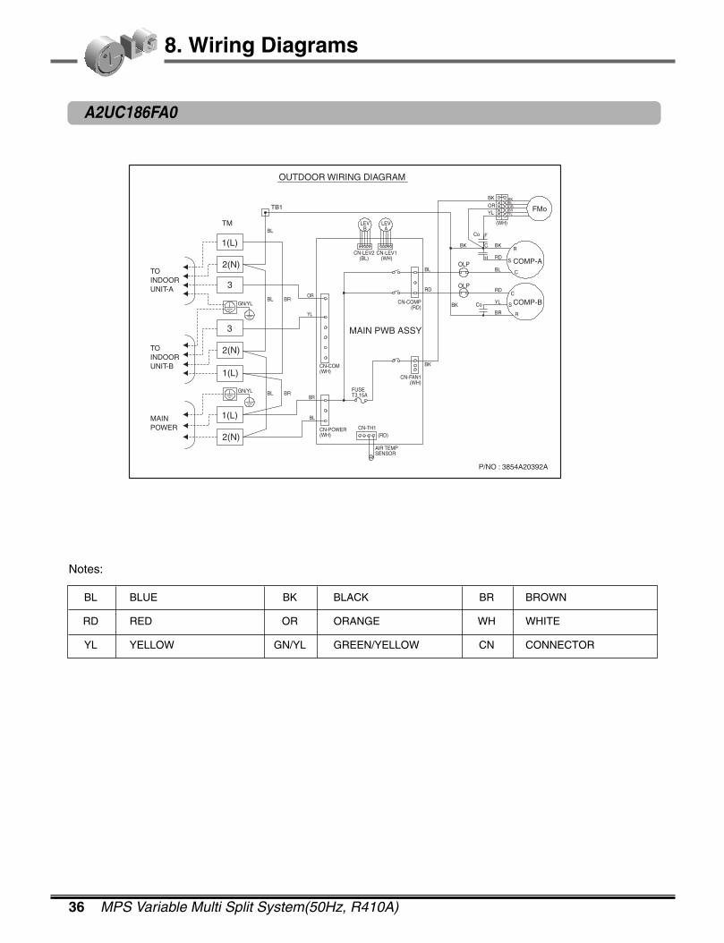
8. Wiring Diagrams
A2UC186FA0
OUTDOOR WIRING DIAGRAM
TM
TB1
OLP
OLP
BL
BL
BL
BR
BRBR
BL
OR
YL
1(L)
2(N)
3
3 MAIN PWB ASSY
CN-COM(WH)
CN-POWER(WH)
CN-TH1
FUSET3.15A
COMP-B
COMP-A
FMo
P/NO : 3854A20392A
CN-FAN1(WH)
CN-COMP(RD)
CN-LEV2(BL)
LEVB
LEVA
CN-LEV1(WH)
AIR TEMPSENSOR
(RD)
BK
RD
BK
BK
Co
Co
BK
BK BKBLORBRYL
ORYL
(WH)
RD
RD
YL
BR
C
C
S
S
R
R
F
C
H
BLBL
2(N)
1(L)
1(L)
2(N)
TOINDOORUNIT-A
TOINDOORUNIT-B
MAINPOWER
GN/YL
GN/YL
Notes:
BL BLUE BK BLACK BR BROWN
RD RED OR ORANGE WH WHITE
YL YELLOW GN/YL GREEN/YELLOW CN CONNECTOR
2004 Product Data 37
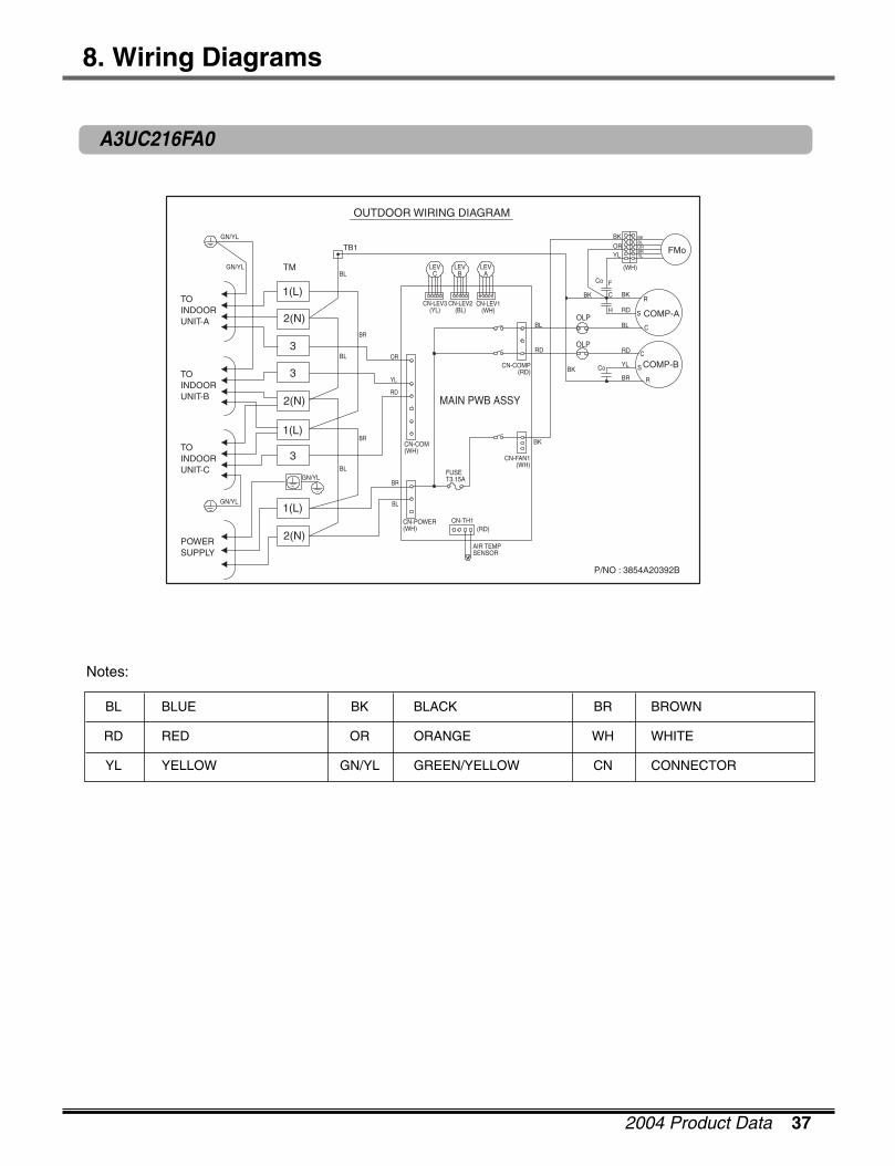
8. Wiring Diagrams
A3UC216FA0
OUTDOOR WIRING DIAGRAM
TB1
BL
BL
BL
BR
BR
OR
YL
RD
BR
BL
MAIN PWB ASSY
P/NO : 3854A20392B
TM
GN/YL
1(L)
2(N)
3
3
3
2(N)
2(N)
1(L)
1(L)
CN-LEV2(BL)
CN-LEV3(YL)
LEVB
LEVC
LEVA
CN-LEV1(WH)
CN-COM(WH)
CN-POWER(WH)
CN-TH1
FUSET3.15A
CN-FAN1(WH)
AIR TEMPSENSOR
(RD)
OLP
OLP
COMP-B
COMP-A
FMo
CN-COMP(RD)
RD
BK
BK
Co
Co
BK
BK BKBLORBRYL
ORYL
(WH)
RD
RD
YL
BR
C
C
S
S
R
R
F
C
H
BL
BK
BL
TOINDOORUNIT-A
TOINDOORUNIT-B
TOINDOORUNIT-C
POWERSUPPLY
GN/YL
GN/YL
GN/YL
Notes:
BL BLUE BK BLACK BR BROWN
RD RED OR ORANGE WH WHITE
YL YELLOW GN/YL GREEN/YELLOW CN CONNECTOR

38 MPS Variable Multi Split System(50Hz, R410A)
8. Wiring Diagrams
A4UC306FA0
OUTDOOR WIRING DIAGRAM
TM
3
2(N)
1(L)
3
3
2(N)
2(N)
1(L)
1(L)
3
TB1
BL
BL
BL
BR
BR
OR
YL
RD
WH
BR
BL
CN-COM(WH)
CN-POWER(WH)
CN-TH1
FUSET3.15A
AIR TEMPSENSOR
(RD)
FMo2CN-FAN1(WH)
CN-FAN2(WH)
BK
BL
(WH)
MAIN PWB ASSY
CN-LEV2(BL)
CN-LEV3(YL)
LEVB
LEVC
CN-LEV4(WH)
LEVD
LEVA
CN-LEV1(WH)
CN-COMP(RD)
RD
BL
TB2
OLP
COMP-B
COMP-A
FMo1
BK
BK
Co
Co
BK
BKBLORBRYL
BKBLORBRYL
(WH)
RD
RD
YL
BR
C
C
S
S
R
R
F
C
H
BL
BKBL
ORBRYL
BKBL
ORBRYL
P/NO : 3854A20392C
F
CH
TOINDOORUNIT-A
TOINDOORUNIT-B
TOINDOORUNIT-C
TOINDOORUNIT-C
POWERSUPPLY
GN/YL
GN/YL
GN/YL
GN/YL
GN/YL
Notes:
BL BLUE BK BLACK BR BROWN
RD RED OR ORANGE WH WHITE
YL YELLOW GN/YL GREEN/YELLOW CN CONNECTOR

2004 Product Data 39
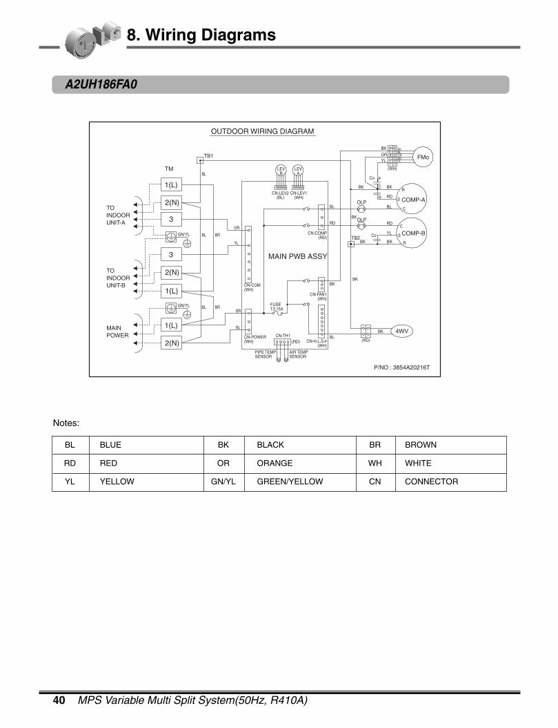
8. Wiring Diagrams
A2UH146FA0
OUTDOOR WIRING DIAGRAM
MAINPOWER
AS/V
CM
FMo
P/NO : 3854A20375A
BS/V
B/PS/V
4WV
MAIN PCB ASSY
BK
BK
BK
BR
BK
BK
T/B1
RD
Co
BL
BL
YL
RD
C
S H C F
R
BKBK
BK
BK
BK
BKWH
WH
BL
RDRD
T/B2
(RD)(BL)
(BK)(W
H)
BL
BK
WH
FUSE 250VT3.15A
BL
BRWH
TO IN
DO
OR
UN
IT
CN
-CO
M
(WH
)C
N-C
OM
CN
-CO
MP
(WH
)C
N-H
,L,S,4
(WH
)C
N-P
OW
ER
PIPE SENSOR
CN-TH1(RD)
(WH
)
1(L)
2(N)
1(L)
2(N)
3(A)
3(B)
A-UNIT
B-UNIT
(RD
)
Notes:
BL BLUE BK BLACK BR BROWN
RD RED OR ORANGE WH WHITE
YL YELLOW GN/YL GREEN/YELLOW CN CONNECTOR
40 MPS Variable Multi Split System(50Hz, R410A)
8. Wiring Diagrams
A2UH186FA0
OUTDOOR WIRING DIAGRAM
TB1
TB2
OLP
OLP
BR
BL
BL
BL BR
BL BR
OR
YL
MAIN PWB ASSY
CN-COM(WH)
CN-POWER(WH)
CN-TH1
FUSET3.15A
CN-H,L,S,4(WH)
4WV
COMP-B
COMP-A
FMo
P/NO : 3854A20216T
CN-FAN1(WH)
CN-COMP(RD)
CN-LEV2(BL)
LEVB
LEVA
CN-LEV1(WH)
AIR TEMPSENSOR
PIPE TEMPSENSOR
(RD)BL
BK
RDBK
BK
Co
Co
BK
BK BKBLORBRYL
ORYL
(WH)
RD
RD
YL
BR
C
C
S
S
R
R
F
C
H
BL
BK
BL
BK
BK
(RD)
TM
1(L)
2(N)
3
3
2(N)
1(L)
1(L)
2(N)
TOINDOORUNIT-A
TOINDOORUNIT-B
MAINPOWER
GN/YL
GN/YL
Notes:
BL BLUE BK BLACK BR BROWN
RD RED OR ORANGE WH WHITE
YL YELLOW GN/YL GREEN/YELLOW CN CONNECTOR

2004 Product Data 41
8. Wiring Diagrams
A3UH216FA0
OUTDOOR WIRING DIAGRAM
BL
MAIN PWB ASSY
4WV
P/NO : 3854A20216U
CN-LEV2(BL)
CN-LEV3(YL)
LEVB
LEVC
LEVA
CN-LEV1(WH)
CN-COM(WH)
CN-POWER(WH)
CN-TH1
FUSET3.15A
PIPE TEMPSENSOR
CN-H,L,S,4(WH)
CN-FAN1(WH)
AIR TEMPSENSOR
(RD)
TB2
OLP
OLP
COMP-B
COMP-A
FMo
CN-COMP(RD)
RDBK
BK
Co
Co
BK
BK BKBLORBRYL
ORYL
(WH)
RD
RD
YL
BR
C
C
S
S
R
R
F
C
H
BL
BK
BK
BK
(RD)
BK
BL
TB1
BL
BL
BL
BR
BR
OR
YL
RD
BR
BL
TM
GN/YL
GN/YL
GN/YL
1(L)
2(N)
3
3
3
2(N)
2(N)
1(L)
1(L)
TOINDOORUNIT-A
TOINDOORUNIT-B
TOINDOORUNIT-C
POWERSUPPLY
GN/YL
Notes:
BL BLUE BK BLACK BR BROWN
RD RED OR ORANGE WH WHITE
YL YELLOW GN/YL GREEN/YELLOW CN CONNECTOR
42 MPS Variable Multi Split System(50Hz, R410A)
8. Wiring Diagrams
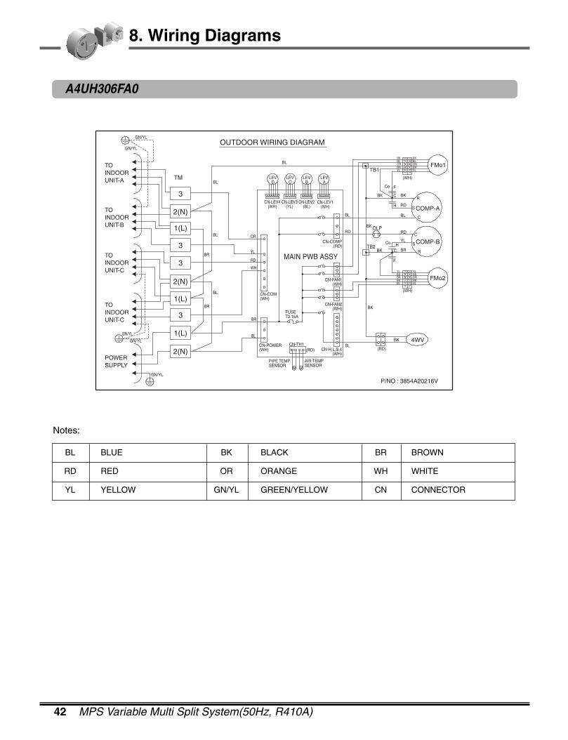
A4UH306FA0
OUTDOOR WIRING DIAGRAM
CN-COM(WH)
CN-POWER(WH)
CN-TH1
FUSET3.15A
PIPE TEMPSENSOR
AIR TEMPSENSOR
(RD)BL
4WV
FMo2
CN-H,L,S,4(WH)
CN-FAN1(WH)
CN-FAN2(WH) BK
BK
(RD)
BK
BL
(WH)
MAIN PWB ASSY
CN-LEV2(BL)
CN-LEV3(YL)
LEVB
LEVC
CN-LEV4(WH)
LEVD
LEVA
CN-LEV1(WH)
CN-COMP(RD)
RD
BL
TB2
OLP
COMP-B
COMP-A
FMo1
BK
BK
Co
Co
BK
BKBLORBRYL
BKBLORBRYL
(WH)
RD
RD
YL
BR
C
C
S
S
R
R
F
C
H
BL
BKBL
ORBRYL
BKBL
ORBRYL
P/NO : 3854A20216V
F
CH
TB1
TM
3
2(N)
1(L)
3
3
2(N)
2(N)
1(L)
1(L)
3
BL
BL
BL
BR
BR
OR
YL
RD
WH
BR
BL
TOINDOORUNIT-A
TOINDOORUNIT-B
TOINDOORUNIT-C
TOINDOORUNIT-C
POWERSUPPLY
GN/YL
GN/YL
GN/YL
GN/YL
GN/YL
Notes:
BL BLUE BK BLACK BR BROWN
RD RED OR ORANGE WH WHITE
YL YELLOW GN/YL GREEN/YELLOW CN CONNECTOR

2004 Product Data 43
9. Piping Diagrams
Heat Exchanger
C.F.F
lndoor unit
:Cooling
: Thermistor
Gas
Ø9.52(3/8)
Ø12.7(1/2)
Liquid
Ø6.35(1/4)
ModelAMNC076LQL0AMNC096LQL0AMNC126LRL0AMNC186LTL0AMNC246LTL0
[unit:mm(inch)]
Refrigerant pipe connection port diameter
Heat Exchanger
Turbo Fan
lndoor unit
:Cooling
: Thermistor
[unit:mm(inch)]
Refrigerant pipe connection port diameter
ModelAMNC096AP*1AMNC126AP*1
Gas
Ø9.52(3/8)
Liquid
Ø6.35(1/4)
9.1 Indoor Unit9.1.1 Cooling Only
Wall Mounted
ART COOL

44 MPS Variable Multi Split System(50Hz, R410A)
9. Piping Diagrams
Heat Exchanger
C.F.F
lndoor unit
:Cooling
: Thermistor
:Heating
[unit:mm(inch)]
Refrigerant pipe connection port diameter
Heat Exchanger
Turbo Fan
lndoor unit
:Cooling:Heating
: Thermistor
[unit:mm(inch)]
Refrigerant pipe connection port diameter
Wall Mounted
ART COOL
9.1.2 Heat Pump
ModelAMNH096AP*1AMNH126AP*1
Gas
Ø9.52(3/8)
Liquid
Ø6.35(1/4)
Gas
Ø9.52(3/8)
Ø12.7(1/2)
Liquid
Ø6.35(1/4)
ModelAMNH076LQL0AMNH096LQL0AMNH126LRL0AMNH186LTL0AMNH246LTL0
2004 Product Data 45
9. Piping Diagrams
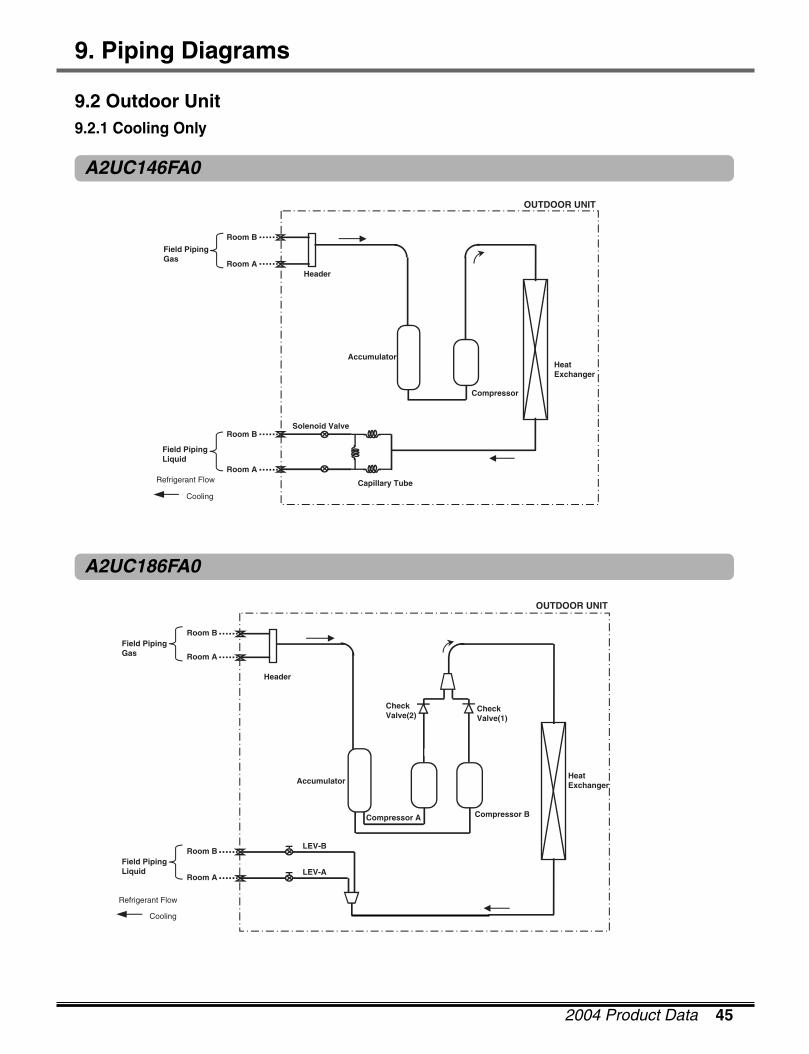
Room B
Accumulator
Compressor
HeatExchanger
HeaderRoom A
Room B
Room A
OUTDOOR UNIT
Field PipingGas
Field PipingLiquid
Refrigerant Flow
Cooling
Capillary Tube
Solenoid Valve
LEV-A
LEV-B
Header
Room B
Room A
Field PipingLiquid
Room A
Field PipingGas
Room B
Accumulator
Compressor A
HeatExchanger
CheckValve(2)
CheckValve(1)
OUTDOOR UNIT
Refrigerant Flow
Cooling
Compressor B
9.2 Outdoor Unit9.2.1 Cooling Only
A2UC146FA0
A2UC186FA0

46 MPS Variable Multi Split System(50Hz, R410A)
9. Piping Diagrams
LEV-A
LEV-B
LEV-C
Header
Room C
Room A
Field PipingLiquid
Room B
Room C
Room A
Field PipingGas
Room B
Accumulator
Hea
tE
xch
ang
er
CheckValve(2)
CheckValve(1)
OUTDOOR UNIT
Refrigerant Flow
Cooling
Compressor A Compressor B
LEV-A
LEV-B
LEV-C
Header
Room C
Room A
Field PipingLiquid Room B
Room C
Room A
Field PipingGas Room B
Accumulator
Hea
tE
xch
ang
er
CheckValve(2)
CheckValve(1)
OUTDOOR UNIT
Refrigerant Flow
Cooling
Compressor A Compressor B
Room D
LEV-DRoom D
A3UC216FA0
A4UC306FA0
2004 Product Data 47
9. Piping Diagrams
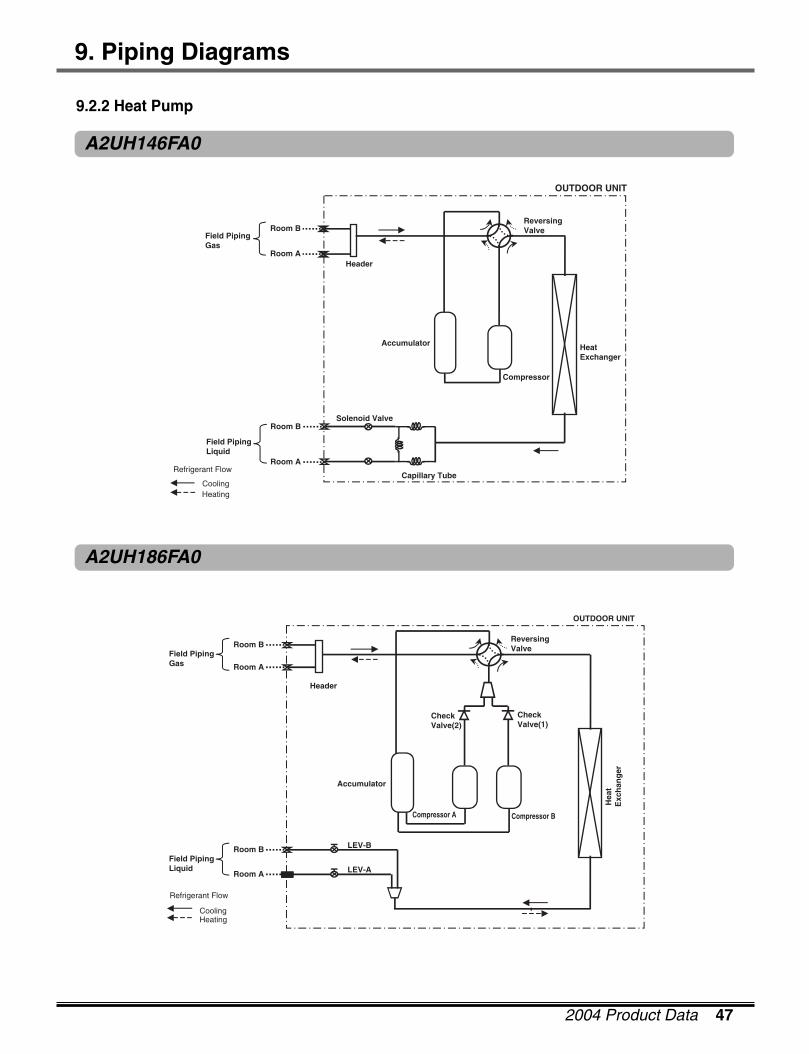
Room B
Accumulator
Compressor
HeatExchanger
HeaderRoom A
OUTDOOR UNIT
Field PipingGas
ReversingValve
Refrigerant Flow
CoolingHeating
Room B
Room A
Field PipingLiquid
Capillary Tube
Solenoid Valve
Accumulator
Hea
tE
xch
ang
er
CheckValve(2)
CheckValve(1)
ReversingValve
OUTDOOR UNIT
Refrigerant Flow
CoolingHeating
LEV-A
LEV-B
Header
Room B
Room A
Field PipingLiquid
Room A
Field PipingGas
Room B
Compressor A Compressor B
A2UH146FA0
A2UH186FA0
9.2.2 Heat Pump
48 MPS Variable Multi Split System(50Hz, R410A)
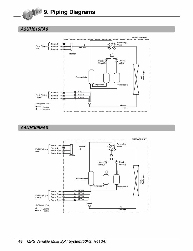
9. Piping Diagrams
Accumulator
LowPressure
Hea
tE
xch
ang
er
CheckValve(2)
CheckValve(1)
ReversingValve
OUTDOOR UNIT
Refrigerant Flow
CoolingHeating
LEV-A
LEV-C
Header
Room C
Room A
Field PipingLiquid
Room A
Field PipingGas
Room C
Compressor A Compressor B
Room B
LEV-BRoom B
Accumulator
Hea
tE
xch
ang
er
CheckValve(2)
CheckValve(1)
ReversingValve
OUTDOOR UNIT
Refrigerant Flow
CoolingHeating
LEV-A
LEV-C
Header
Room C
Room A
Field PipingLiquid
Room A
Field PipingGas
Room C
Compressor A Compressor B
Room B
LEV-BRoom B
Room D
LEV-DRoom D
A3UH216FA0
A4UH306FA0
2004 Product Data 49
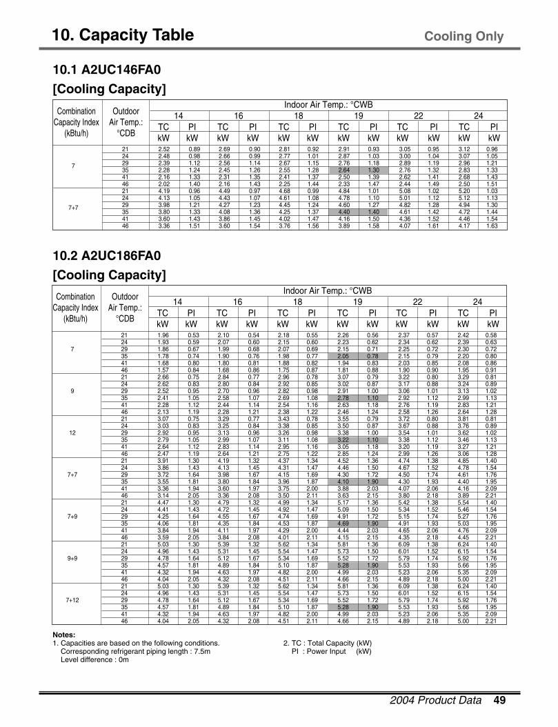
10. Capacity Table
10.1 A2UC146FA0
[Cooling Capacity]
10.2 A2UC186FA0
[Cooling Capacity]
TC PI TC PI TC PI TC PI TC PI TC PIkW kW kW kW kW kW kW kW kW kW kW kW
CombinationCapacity Index
(kBtu/h)
Outdoor Air Temp.:
°CDB
14 16 18 19 22 24 Indoor Air Temp.: °CWB
21 1.96 0.53 2.10 0.54 2.18 0.55 2.26 0.56 2.37 0.57 2.42 0.58 24 1.93 0.59 2.07 0.60 2.15 0.60 2.23 0.62 2.34 0.62 2.39 0.63
7 29 1.86 0.67 1.99 0.68 2.07 0.69 2.15 0.71 2.25 0.72 2.30 0.72 35 1.78 0.74 1.90 0.76 1.98 0.77 2.05 0.78 2.15 0.79 2.20 0.80 41 1.68 0.80 1.80 0.81 1.88 0.82 1.94 0.83 2.03 0.85 2.08 0.86 46 1.57 0.84 1.68 0.86 1.75 0.87 1.81 0.88 1.90 0.90 1.95 0.91 21 2.66 0.75 2.84 0.77 2.96 0.78 3.07 0.79 3.22 0.80 3.29 0.81 24 2.62 0.83 2.80 0.84 2.92 0.85 3.02 0.87 3.17 0.88 3.24 0.89
9 29 2.52 0.95 2.70 0.96 2.82 0.98 2.91 1.00 3.06 1.01 3.13 1.02 35 2.41 1.05 2.58 1.07 2.69 1.08 2.78 1.10 2.92 1.12 2.99 1.13 41 2.28 1.12 2.44 1.14 2.54 1.16 2.63 1.18 2.76 1.19 2.83 1.21 46 2.13 1.19 2.28 1.21 2.38 1.22 2.46 1.24 2.58 1.26 2.64 1.28 21 3.07 0.75 3.29 0.77 3.43 0.78 3.55 0.79 3.72 0.80 3.81 0.81 24 3.03 0.83 3.25 0.84 3.38 0.85 3.50 0.87 3.67 0.88 3.76 0.89
12 29 2.92 0.95 3.13 0.96 3.26 0.98 3.38 1.00 3.54 1.01 3.62 1.02 35 2.79 1.05 2.99 1.07 3.11 1.08 3.22 1.10 3.38 1.12 3.46 1.13 41 2.64 1.12 2.83 1.14 2.95 1.16 3.05 1.18 3.20 1.19 3.27 1.21 46 2.47 1.19 2.64 1.21 2.75 1.22 2.85 1.24 2.99 1.26 3.06 1.28 21 3.91 1.30 4.19 1.32 4.37 1.34 4.52 1.36 4.74 1.38 4.85 1.40 24 3.86 1.43 4.13 1.45 4.31 1.47 4.46 1.50 4.67 1.52 4.78 1.54
7+7 29 3.72 1.64 3.98 1.67 4.15 1.69 4.30 1.72 4.50 1.74 4.61 1.76 35 3.55 1.81 3.80 1.84 3.96 1.87 4.10 1.90 4.30 1.93 4.40 1.95 41 3.36 1.94 3.60 1.97 3.75 2.00 3.88 2.03 4.07 2.06 4.16 2.09 46 3.14 2.05 3.36 2.08 3.50 2.11 3.63 2.15 3.80 2.18 3.89 2.21 21 4.47 1.30 4.79 1.32 4.99 1.34 5.17 1.36 5.42 1.38 5.54 1.40 24 4.41 1.43 4.72 1.45 4.92 1.47 5.09 1.50 5.34 1.52 5.46 1.54
7+9 29 4.25 1.64 4.55 1.67 4.74 1.69 4.91 1.72 5.15 1.74 5.27 1.76 35 4.06 1.81 4.35 1.84 4.53 1.87 4.69 1.90 4.91 1.93 5.03 1.95 41 3.84 1.94 4.11 1.97 4.29 2.00 4.44 2.03 4.65 2.06 4.76 2.09 46 3.59 2.05 3.84 2.08 4.01 2.11 4.15 2.15 4.35 2.18 4.45 2.21 21 5.03 1.30 5.39 1.32 5.62 1.34 5.81 1.36 6.09 1.38 6.24 1.40 24 4.96 1.43 5.31 1.45 5.54 1.47 5.73 1.50 6.01 1.52 6.15 1.54
9+9 29 4.78 1.64 5.12 1.67 5.34 1.69 5.52 1.72 5.79 1.74 5.92 1.76 35 4.57 1.81 4.89 1.84 5.10 1.87 5.28 1.90 5.53 1.93 5.66 1.95 41 4.32 1.94 4.63 1.97 4.82 2.00 4.99 2.03 5.23 2.06 5.35 2.09 46 4.04 2.05 4.32 2.08 4.51 2.11 4.66 2.15 4.89 2.18 5.00 2.21 21 5.03 1.30 5.39 1.32 5.62 1.34 5.81 1.36 6.09 1.38 6.24 1.40 24 4.96 1.43 5.31 1.45 5.54 1.47 5.73 1.50 6.01 1.52 6.15 1.54
7+12 29 4.78 1.64 5.12 1.67 5.34 1.69 5.52 1.72 5.79 1.74 5.92 1.76 35 4.57 1.81 4.89 1.84 5.10 1.87 5.28 1.90 5.53 1.93 5.66 1.95 41 4.32 1.94 4.63 1.97 4.82 2.00 4.99 2.03 5.23 2.06 5.35 2.09 46 4.04 2.05 4.32 2.08 4.51 2.11 4.66 2.15 4.89 2.18 5.00 2.21
Cooling Only
Notes:1. Capacities are based on the following conditions.
Corresponding refrigerant piping length : 7.5mLevel difference : 0m
2. TC : Total Capacity (kW)PI : Power Input (kW)
TC PI TC PI TC PI TC PI TC PI TC PIkW kW kW kW kW kW kW kW kW kW kW kW
CombinationCapacity Index
(kBtu/h)
Outdoor Air Temp.:
°CDB
14 16 18 19 22 24 Indoor Air Temp.: °CWB
21 2.52 0.89 2.69 0.90 2.81 0.92 2.91 0.93 3.05 0.95 3.12 0.96 24 2.48 0.98 2.66 0.99 2.77 1.01 2.87 1.03 3.00 1.04 3.07 1.05
7 29 2.39 1.12 2.56 1.14 2.67 1.15 2.76 1.18 2.89 1.19 2.96 1.21 35 2.28 1.24 2.45 1.26 2.55 1.28 2.64 1.30 2.76 1.32 2.83 1.33 41 2.16 1.33 2.31 1.35 2.41 1.37 2.50 1.39 2.62 1.41 2.68 1.43 46 2.02 1.40 2.16 1.43 2.25 1.44 2.33 1.47 2.44 1.49 2.50 1.51 21 4.19 0.96 4.49 0.97 4.68 0.99 4.84 1.01 5.08 1.02 5.20 1.03 24 4.13 1.05 4.43 1.07 4.61 1.08 4.78 1.10 5.01 1.12 5.12 1.13
7+7 29 3.98 1.21 4.27 1.23 4.45 1.24 4.60 1.27 4.82 1.28 4.94 1.30 35 3.80 1.33 4.08 1.36 4.25 1.37 4.40 1.40 4.61 1.42 4.72 1.44 41 3.60 1.43 3.86 1.45 4.02 1.47 4.16 1.50 4.36 1.52 4.46 1.54 46 3.36 1.51 3.60 1.54 3.76 1.56 3.89 1.58 4.07 1.61 4.17 1.63
50 MPS Variable Multi Split System(50Hz, R410A)
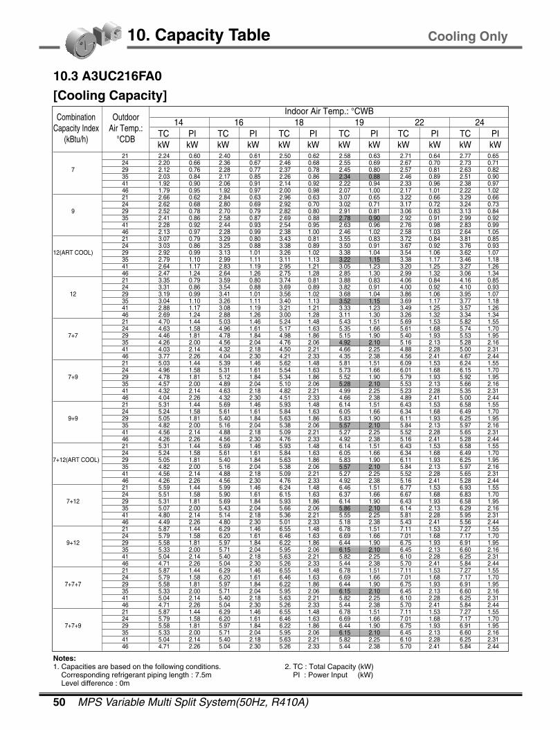
10. Capacity Table
10.3 A3UC216FA0
[Cooling Capacity]
TC PI TC PI TC PI TC PI TC PI TC PIkW kW kW kW kW kW kW kW kW kW kW kW
CombinationCapacity Index
(kBtu/h)
Outdoor Air Temp.:
°CDB
14 16 18 19 22 24 Indoor Air Temp.: °CWB
21 2.24 0.60 2.40 0.61 2.50 0.62 2.58 0.63 2.71 0.64 2.77 0.65 24 2.20 0.66 2.36 0.67 2.46 0.68 2.55 0.69 2.67 0.70 2.73 0.71
7 29 2.12 0.76 2.28 0.77 2.37 0.78 2.45 0.80 2.57 0.81 2.63 0.82 35 2.03 0.84 2.17 0.85 2.26 0.86 2.34 0.88 2.46 0.89 2.51 0.90 41 1.92 0.90 2.06 0.91 2.14 0.92 2.22 0.94 2.33 0.96 2.38 0.97 46 1.79 0.95 1.92 0.97 2.00 0.98 2.07 1.00 2.17 1.01 2.22 1.02 21 2.66 0.62 2.84 0.63 2.96 0.63 3.07 0.65 3.22 0.66 3.29 0.66 24 2.62 0.68 2.80 0.69 2.92 0.70 3.02 0.71 3.17 0.72 3.24 0.73
9 29 2.52 0.78 2.70 0.79 2.82 0.80 2.91 0.81 3.06 0.83 3.13 0.84 35 2.41 0.86 2.58 0.87 2.69 0.88 2.78 0.90 2.92 0.91 2.99 0.92 41 2.28 0.92 2.44 0.93 2.54 0.95 2.63 0.96 2.76 0.98 2.83 0.99 46 2.13 0.97 2.28 0.99 2.38 1.00 2.46 1.02 2.58 1.03 2.64 1.05 21 3.07 0.79 3.29 0.80 3.43 0.81 3.55 0.83 3.72 0.84 3.81 0.85 24 3.03 0.86 3.25 0.88 3.38 0.89 3.50 0.91 3.67 0.92 3.76 0.93
12(ART COOL) 29 2.92 0.99 3.13 1.01 3.26 1.02 3.38 1.04 3.54 1.06 3.62 1.07 35 2.79 1.10 2.99 1.11 3.11 1.13 3.22 1.15 3.38 1.17 3.46 1.18 41 2.64 1.17 2.83 1.19 2.95 1.21 3.05 1.23 3.20 1.25 3.27 1.26 46 2.47 1.24 2.64 1.26 2.75 1.28 2.85 1.30 2.99 1.32 3.06 1.34 21 3.35 0.79 3.59 0.80 3.74 0.81 3.88 0.83 4.06 0.84 4.16 0.85 24 3.31 0.86 3.54 0.88 3.69 0.89 3.82 0.91 4.00 0.92 4.10 0.93
12 29 3.19 0.99 3.41 1.01 3.56 1.02 3.68 1.04 3.86 1.06 3.95 1.07 35 3.04 1.10 3.26 1.11 3.40 1.13 3.52 1.15 3.69 1.17 3.77 1.18 41 2.88 1.17 3.08 1.19 3.21 1.21 3.33 1.23 3.49 1.25 3.57 1.26 46 2.69 1.24 2.88 1.26 3.00 1.28 3.11 1.30 3.26 1.32 3.34 1.34 21 4.70 1.44 5.03 1.46 5.24 1.48 5.43 1.51 5.69 1.53 5.82 1.55 24 4.63 1.58 4.96 1.61 5.17 1.63 5.35 1.66 5.61 1.68 5.74 1.70
7+7 29 4.46 1.81 4.78 1.84 4.98 1.86 5.15 1.90 5.40 1.93 5.53 1.95 35 4.26 2.00 4.56 2.04 4.76 2.06 4.92 2.10 5.16 2.13 5.28 2.16 41 4.03 2.14 4.32 2.18 4.50 2.21 4.66 2.25 4.88 2.28 5.00 2.31 46 3.77 2.26 4.04 2.30 4.21 2.33 4.35 2.38 4.56 2.41 4.67 2.44 21 5.03 1.44 5.39 1.46 5.62 1.48 5.81 1.51 6.09 1.53 6.24 1.55 24 4.96 1.58 5.31 1.61 5.54 1.63 5.73 1.66 6.01 1.68 6.15 1.70
7+9 29 4.78 1.81 5.12 1.84 5.34 1.86 5.52 1.90 5.79 1.93 5.92 1.95 35 4.57 2.00 4.89 2.04 5.10 2.06 5.28 2.10 5.53 2.13 5.66 2.16 41 4.32 2.14 4.63 2.18 4.82 2.21 4.99 2.25 5.23 2.28 5.35 2.31 46 4.04 2.26 4.32 2.30 4.51 2.33 4.66 2.38 4.89 2.41 5.00 2.44 21 5.31 1.44 5.69 1.46 5.93 1.48 6.14 1.51 6.43 1.53 6.58 1.55 24 5.24 1.58 5.61 1.61 5.84 1.63 6.05 1.66 6.34 1.68 6.49 1.70
9+9 29 5.05 1.81 5.40 1.84 5.63 1.86 5.83 1.90 6.11 1.93 6.25 1.95 35 4.82 2.00 5.16 2.04 5.38 2.06 5.57 2.10 5.84 2.13 5.97 2.16 41 4.56 2.14 4.88 2.18 5.09 2.21 5.27 2.25 5.52 2.28 5.65 2.31 46 4.26 2.26 4.56 2.30 4.76 2.33 4.92 2.38 5.16 2.41 5.28 2.44 21 5.31 1.44 5.69 1.46 5.93 1.48 6.14 1.51 6.43 1.53 6.58 1.55 24 5.24 1.58 5.61 1.61 5.84 1.63 6.05 1.66 6.34 1.68 6.49 1.70
7+12(ART COOL) 29 5.05 1.81 5.40 1.84 5.63 1.86 5.83 1.90 6.11 1.93 6.25 1.95 35 4.82 2.00 5.16 2.04 5.38 2.06 5.57 2.10 5.84 2.13 5.97 2.16 41 4.56 2.14 4.88 2.18 5.09 2.21 5.27 2.25 5.52 2.28 5.65 2.31 46 4.26 2.26 4.56 2.30 4.76 2.33 4.92 2.38 5.16 2.41 5.28 2.44 21 5.59 1.44 5.99 1.46 6.24 1.48 6.46 1.51 6.77 1.53 6.93 1.55 24 5.51 1.58 5.90 1.61 6.15 1.63 6.37 1.66 6.67 1.68 6.83 1.70
7+12 29 5.31 1.81 5.69 1.84 5.93 1.86 6.14 1.90 6.43 1.93 6.58 1.95 35 5.07 2.00 5.43 2.04 5.66 2.06 5.86 2.10 6.14 2.13 6.29 2.16 41 4.80 2.14 5.14 2.18 5.36 2.21 5.55 2.25 5.81 2.28 5.95 2.31 46 4.49 2.26 4.80 2.30 5.01 2.33 5.18 2.38 5.43 2.41 5.56 2.44 21 5.87 1.44 6.29 1.46 6.55 1.48 6.78 1.51 7.11 1.53 7.27 1.55 24 5.79 1.58 6.20 1.61 6.46 1.63 6.69 1.66 7.01 1.68 7.17 1.70
9+12 29 5.58 1.81 5.97 1.84 6.22 1.86 6.44 1.90 6.75 1.93 6.91 1.95 35 5.33 2.00 5.71 2.04 5.95 2.06 6.15 2.10 6.45 2.13 6.60 2.16 41 5.04 2.14 5.40 2.18 5.63 2.21 5.82 2.25 6.10 2.28 6.25 2.31 46 4.71 2.26 5.04 2.30 5.26 2.33 5.44 2.38 5.70 2.41 5.84 2.44 21 5.87 1.44 6.29 1.46 6.55 1.48 6.78 1.51 7.11 1.53 7.27 1.55 24 5.79 1.58 6.20 1.61 6.46 1.63 6.69 1.66 7.01 1.68 7.17 1.70
7+7+7 29 5.58 1.81 5.97 1.84 6.22 1.86 6.44 1.90 6.75 1.93 6.91 1.95 35 5.33 2.00 5.71 2.04 5.95 2.06 6.15 2.10 6.45 2.13 6.60 2.16 41 5.04 2.14 5.40 2.18 5.63 2.21 5.82 2.25 6.10 2.28 6.25 2.31 46 4.71 2.26 5.04 2.30 5.26 2.33 5.44 2.38 5.70 2.41 5.84 2.44 21 5.87 1.44 6.29 1.46 6.55 1.48 6.78 1.51 7.11 1.53 7.27 1.55 24 5.79 1.58 6.20 1.61 6.46 1.63 6.69 1.66 7.01 1.68 7.17 1.70
7+7+9 29 5.58 1.81 5.97 1.84 6.22 1.86 6.44 1.90 6.75 1.93 6.91 1.95 35 5.33 2.00 5.71 2.04 5.95 2.06 6.15 2.10 6.45 2.13 6.60 2.16 41 5.04 2.14 5.40 2.18 5.63 2.21 5.82 2.25 6.10 2.28 6.25 2.31 46 4.71 2.26 5.04 2.30 5.26 2.33 5.44 2.38 5.70 2.41 5.84 2.44
Notes:1. Capacities are based on the following conditions.
Corresponding refrigerant piping length : 7.5mLevel difference : 0m
2. TC : Total Capacity (kW)PI : Power Input (kW)
Cooling Only
2004 Product Data 51
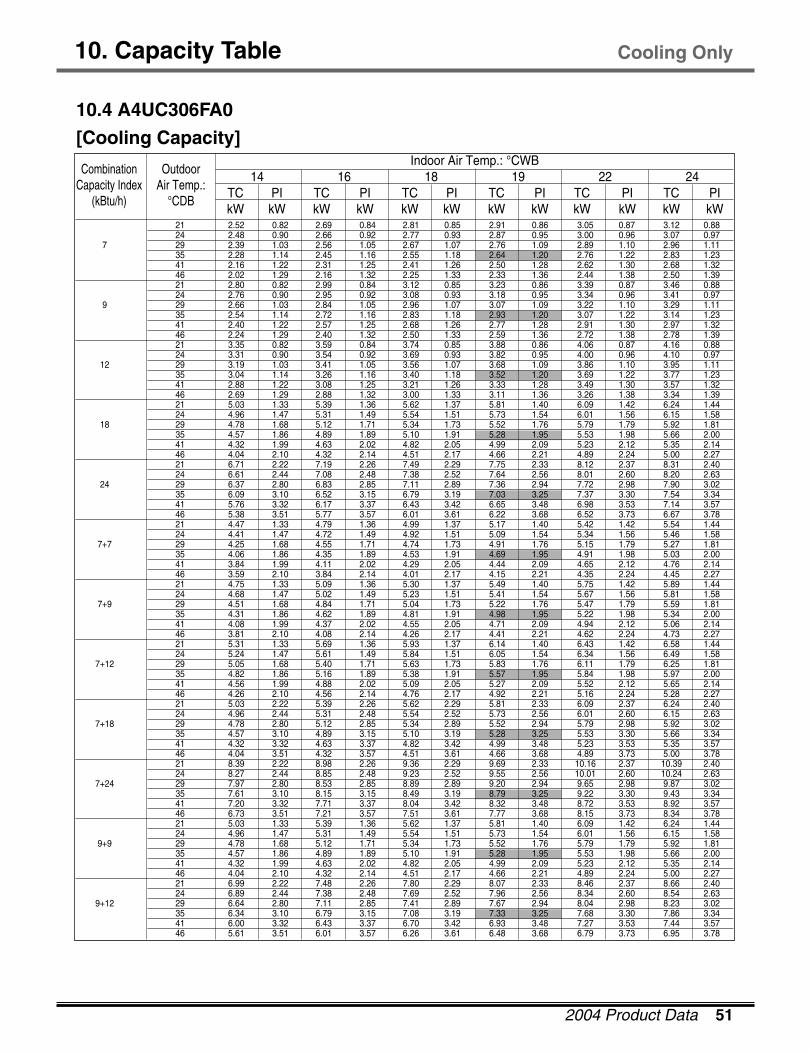
10. Capacity Table
10.4 A4UC306FA0
[Cooling Capacity]
TC PI TC PI TC PI TC PI TC PI TC PIkW kW kW kW kW kW kW kW kW kW kW kW
CombinationCapacity Index
(kBtu/h)
Outdoor Air Temp.:
°CDB
14 16 18 19 22 24 Indoor Air Temp.: °CWB
21 2.52 0.82 2.69 0.84 2.81 0.85 2.91 0.86 3.05 0.87 3.12 0.88 24 2.48 0.90 2.66 0.92 2.77 0.93 2.87 0.95 3.00 0.96 3.07 0.97
7 29 2.39 1.03 2.56 1.05 2.67 1.07 2.76 1.09 2.89 1.10 2.96 1.11 35 2.28 1.14 2.45 1.16 2.55 1.18 2.64 1.20 2.76 1.22 2.83 1.23 41 2.16 1.22 2.31 1.25 2.41 1.26 2.50 1.28 2.62 1.30 2.68 1.32 46 2.02 1.29 2.16 1.32 2.25 1.33 2.33 1.36 2.44 1.38 2.50 1.39 21 2.80 0.82 2.99 0.84 3.12 0.85 3.23 0.86 3.39 0.87 3.46 0.88 24 2.76 0.90 2.95 0.92 3.08 0.93 3.18 0.95 3.34 0.96 3.41 0.97
9 29 2.66 1.03 2.84 1.05 2.96 1.07 3.07 1.09 3.22 1.10 3.29 1.11 35 2.54 1.14 2.72 1.16 2.83 1.18 2.93 1.20 3.07 1.22 3.14 1.23 41 2.40 1.22 2.57 1.25 2.68 1.26 2.77 1.28 2.91 1.30 2.97 1.32 46 2.24 1.29 2.40 1.32 2.50 1.33 2.59 1.36 2.72 1.38 2.78 1.39 21 3.35 0.82 3.59 0.84 3.74 0.85 3.88 0.86 4.06 0.87 4.16 0.88 24 3.31 0.90 3.54 0.92 3.69 0.93 3.82 0.95 4.00 0.96 4.10 0.97
12 29 3.19 1.03 3.41 1.05 3.56 1.07 3.68 1.09 3.86 1.10 3.95 1.11 35 3.04 1.14 3.26 1.16 3.40 1.18 3.52 1.20 3.69 1.22 3.77 1.23 41 2.88 1.22 3.08 1.25 3.21 1.26 3.33 1.28 3.49 1.30 3.57 1.32 46 2.69 1.29 2.88 1.32 3.00 1.33 3.11 1.36 3.26 1.38 3.34 1.39 21 5.03 1.33 5.39 1.36 5.62 1.37 5.81 1.40 6.09 1.42 6.24 1.44 24 4.96 1.47 5.31 1.49 5.54 1.51 5.73 1.54 6.01 1.56 6.15 1.58
18 29 4.78 1.68 5.12 1.71 5.34 1.73 5.52 1.76 5.79 1.79 5.92 1.81 35 4.57 1.86 4.89 1.89 5.10 1.91 5.28 1.95 5.53 1.98 5.66 2.00 41 4.32 1.99 4.63 2.02 4.82 2.05 4.99 2.09 5.23 2.12 5.35 2.14 46 4.04 2.10 4.32 2.14 4.51 2.17 4.66 2.21 4.89 2.24 5.00 2.27 21 6.71 2.22 7.19 2.26 7.49 2.29 7.75 2.33 8.12 2.37 8.31 2.40 24 6.61 2.44 7.08 2.48 7.38 2.52 7.64 2.56 8.01 2.60 8.20 2.63
24 29 6.37 2.80 6.83 2.85 7.11 2.89 7.36 2.94 7.72 2.98 7.90 3.02 35 6.09 3.10 6.52 3.15 6.79 3.19 7.03 3.25 7.37 3.30 7.54 3.34 41 5.76 3.32 6.17 3.37 6.43 3.42 6.65 3.48 6.98 3.53 7.14 3.57 46 5.38 3.51 5.77 3.57 6.01 3.61 6.22 3.68 6.52 3.73 6.67 3.78 21 4.47 1.33 4.79 1.36 4.99 1.37 5.17 1.40 5.42 1.42 5.54 1.44 24 4.41 1.47 4.72 1.49 4.92 1.51 5.09 1.54 5.34 1.56 5.46 1.58
7+7 29 4.25 1.68 4.55 1.71 4.74 1.73 4.91 1.76 5.15 1.79 5.27 1.81 35 4.06 1.86 4.35 1.89 4.53 1.91 4.69 1.95 4.91 1.98 5.03 2.00 41 3.84 1.99 4.11 2.02 4.29 2.05 4.44 2.09 4.65 2.12 4.76 2.14 46 3.59 2.10 3.84 2.14 4.01 2.17 4.15 2.21 4.35 2.24 4.45 2.27 21 4.75 1.33 5.09 1.36 5.30 1.37 5.49 1.40 5.75 1.42 5.89 1.44 24 4.68 1.47 5.02 1.49 5.23 1.51 5.41 1.54 5.67 1.56 5.81 1.58
7+9 29 4.51 1.68 4.84 1.71 5.04 1.73 5.22 1.76 5.47 1.79 5.59 1.81 35 4.31 1.86 4.62 1.89 4.81 1.91 4.98 1.95 5.22 1.98 5.34 2.00 41 4.08 1.99 4.37 2.02 4.55 2.05 4.71 2.09 4.94 2.12 5.06 2.14 46 3.81 2.10 4.08 2.14 4.26 2.17 4.41 2.21 4.62 2.24 4.73 2.27 21 5.31 1.33 5.69 1.36 5.93 1.37 6.14 1.40 6.43 1.42 6.58 1.44 24 5.24 1.47 5.61 1.49 5.84 1.51 6.05 1.54 6.34 1.56 6.49 1.58
7+12 29 5.05 1.68 5.40 1.71 5.63 1.73 5.83 1.76 6.11 1.79 6.25 1.81 35 4.82 1.86 5.16 1.89 5.38 1.91 5.57 1.95 5.84 1.98 5.97 2.00 41 4.56 1.99 4.88 2.02 5.09 2.05 5.27 2.09 5.52 2.12 5.65 2.14 46 4.26 2.10 4.56 2.14 4.76 2.17 4.92 2.21 5.16 2.24 5.28 2.27 21 5.03 2.22 5.39 2.26 5.62 2.29 5.81 2.33 6.09 2.37 6.24 2.40 24 4.96 2.44 5.31 2.48 5.54 2.52 5.73 2.56 6.01 2.60 6.15 2.63
7+18 29 4.78 2.80 5.12 2.85 5.34 2.89 5.52 2.94 5.79 2.98 5.92 3.02 35 4.57 3.10 4.89 3.15 5.10 3.19 5.28 3.25 5.53 3.30 5.66 3.34 41 4.32 3.32 4.63 3.37 4.82 3.42 4.99 3.48 5.23 3.53 5.35 3.57 46 4.04 3.51 4.32 3.57 4.51 3.61 4.66 3.68 4.89 3.73 5.00 3.78 21 8.39 2.22 8.98 2.26 9.36 2.29 9.69 2.33 10.16 2.37 10.39 2.40 24 8.27 2.44 8.85 2.48 9.23 2.52 9.55 2.56 10.01 2.60 10.24 2.63
7+24 29 7.97 2.80 8.53 2.85 8.89 2.89 9.20 2.94 9.65 2.98 9.87 3.02 35 7.61 3.10 8.15 3.15 8.49 3.19 8.79 3.25 9.22 3.30 9.43 3.34 41 7.20 3.32 7.71 3.37 8.04 3.42 8.32 3.48 8.72 3.53 8.92 3.57 46 6.73 3.51 7.21 3.57 7.51 3.61 7.77 3.68 8.15 3.73 8.34 3.78 21 5.03 1.33 5.39 1.36 5.62 1.37 5.81 1.40 6.09 1.42 6.24 1.44 24 4.96 1.47 5.31 1.49 5.54 1.51 5.73 1.54 6.01 1.56 6.15 1.58
9+9 29 4.78 1.68 5.12 1.71 5.34 1.73 5.52 1.76 5.79 1.79 5.92 1.81 35 4.57 1.86 4.89 1.89 5.10 1.91 5.28 1.95 5.53 1.98 5.66 2.00 41 4.32 1.99 4.63 2.02 4.82 2.05 4.99 2.09 5.23 2.12 5.35 2.14 46 4.04 2.10 4.32 2.14 4.51 2.17 4.66 2.21 4.89 2.24 5.00 2.27 21 6.99 2.22 7.48 2.26 7.80 2.29 8.07 2.33 8.46 2.37 8.66 2.40 24 6.89 2.44 7.38 2.48 7.69 2.52 7.96 2.56 8.34 2.60 8.54 2.63
9+12 29 6.64 2.80 7.11 2.85 7.41 2.89 7.67 2.94 8.04 2.98 8.23 3.02 35 6.34 3.10 6.79 3.15 7.08 3.19 7.33 3.25 7.68 3.30 7.86 3.34 41 6.00 3.32 6.43 3.37 6.70 3.42 6.93 3.48 7.27 3.53 7.44 3.57 46 5.61 3.51 6.01 3.57 6.26 3.61 6.48 3.68 6.79 3.73 6.95 3.78
Cooling Only
52 MPS Variable Multi Split System(50Hz, R410A)
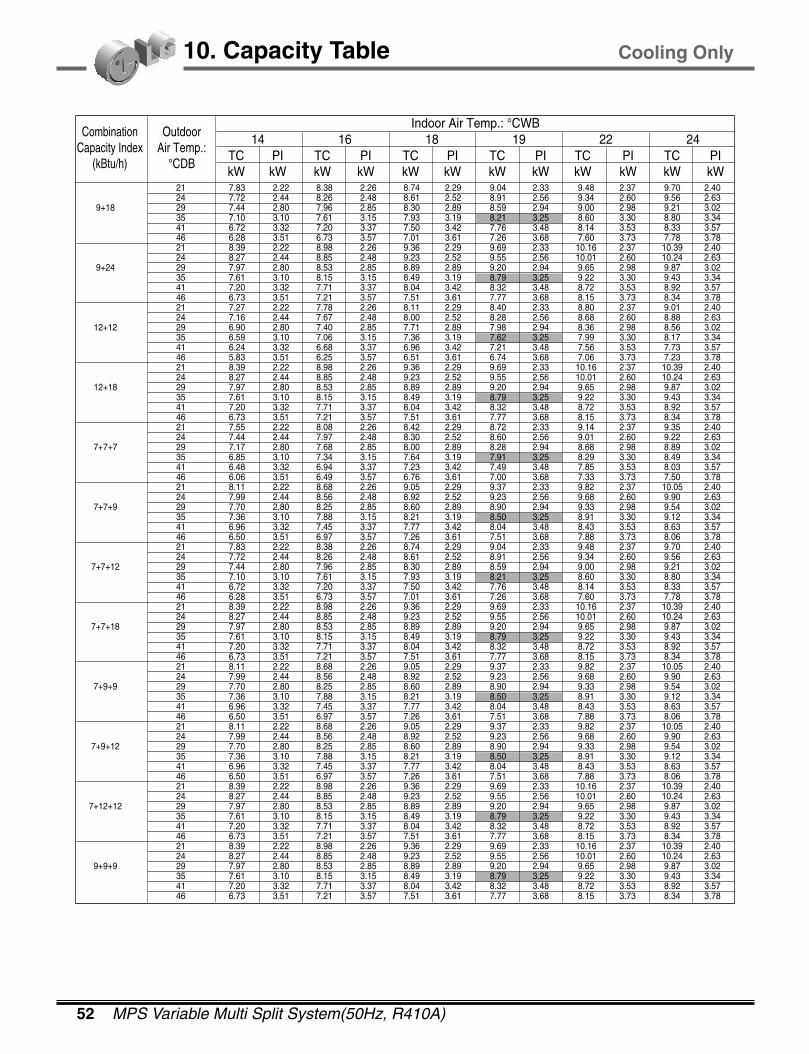
10. Capacity Table
TC PI TC PI TC PI TC PI TC PI TC PIkW kW kW kW kW kW kW kW kW kW kW kW
CombinationCapacity Index
(kBtu/h)
Outdoor Air Temp.:
°CDB
14 16 18 19 22 24 Indoor Air Temp.: °CWB
21 7.83 2.22 8.38 2.26 8.74 2.29 9.04 2.33 9.48 2.37 9.70 2.40 24 7.72 2.44 8.26 2.48 8.61 2.52 8.91 2.56 9.34 2.60 9.56 2.63
9+18 29 7.44 2.80 7.96 2.85 8.30 2.89 8.59 2.94 9.00 2.98 9.21 3.02 35 7.10 3.10 7.61 3.15 7.93 3.19 8.21 3.25 8.60 3.30 8.80 3.34 41 6.72 3.32 7.20 3.37 7.50 3.42 7.76 3.48 8.14 3.53 8.33 3.57 46 6.28 3.51 6.73 3.57 7.01 3.61 7.26 3.68 7.60 3.73 7.78 3.78 21 8.39 2.22 8.98 2.26 9.36 2.29 9.69 2.33 10.16 2.37 10.39 2.40 24 8.27 2.44 8.85 2.48 9.23 2.52 9.55 2.56 10.01 2.60 10.24 2.63
9+24 29 7.97 2.80 8.53 2.85 8.89 2.89 9.20 2.94 9.65 2.98 9.87 3.02 35 7.61 3.10 8.15 3.15 8.49 3.19 8.79 3.25 9.22 3.30 9.43 3.34 41 7.20 3.32 7.71 3.37 8.04 3.42 8.32 3.48 8.72 3.53 8.92 3.57 46 6.73 3.51 7.21 3.57 7.51 3.61 7.77 3.68 8.15 3.73 8.34 3.78 21 7.27 2.22 7.78 2.26 8.11 2.29 8.40 2.33 8.80 2.37 9.01 2.40 24 7.16 2.44 7.67 2.48 8.00 2.52 8.28 2.56 8.68 2.60 8.88 2.63
12+12 29 6.90 2.80 7.40 2.85 7.71 2.89 7.98 2.94 8.36 2.98 8.56 3.02 35 6.59 3.10 7.06 3.15 7.36 3.19 7.62 3.25 7.99 3.30 8.17 3.34 41 6.24 3.32 6.68 3.37 6.96 3.42 7.21 3.48 7.56 3.53 7.73 3.57 46 5.83 3.51 6.25 3.57 6.51 3.61 6.74 3.68 7.06 3.73 7.23 3.78 21 8.39 2.22 8.98 2.26 9.36 2.29 9.69 2.33 10.16 2.37 10.39 2.40 24 8.27 2.44 8.85 2.48 9.23 2.52 9.55 2.56 10.01 2.60 10.24 2.63
12+18 29 7.97 2.80 8.53 2.85 8.89 2.89 9.20 2.94 9.65 2.98 9.87 3.02 35 7.61 3.10 8.15 3.15 8.49 3.19 8.79 3.25 9.22 3.30 9.43 3.34 41 7.20 3.32 7.71 3.37 8.04 3.42 8.32 3.48 8.72 3.53 8.92 3.57 46 6.73 3.51 7.21 3.57 7.51 3.61 7.77 3.68 8.15 3.73 8.34 3.78 21 7.55 2.22 8.08 2.26 8.42 2.29 8.72 2.33 9.14 2.37 9.35 2.40 24 7.44 2.44 7.97 2.48 8.30 2.52 8.60 2.56 9.01 2.60 9.22 2.63
7+7+7 29 7.17 2.80 7.68 2.85 8.00 2.89 8.28 2.94 8.68 2.98 8.89 3.02 35 6.85 3.10 7.34 3.15 7.64 3.19 7.91 3.25 8.29 3.30 8.49 3.34 41 6.48 3.32 6.94 3.37 7.23 3.42 7.49 3.48 7.85 3.53 8.03 3.57 46 6.06 3.51 6.49 3.57 6.76 3.61 7.00 3.68 7.33 3.73 7.50 3.78 21 8.11 2.22 8.68 2.26 9.05 2.29 9.37 2.33 9.82 2.37 10.05 2.40 24 7.99 2.44 8.56 2.48 8.92 2.52 9.23 2.56 9.68 2.60 9.90 2.63
7+7+9 29 7.70 2.80 8.25 2.85 8.60 2.89 8.90 2.94 9.33 2.98 9.54 3.02 35 7.36 3.10 7.88 3.15 8.21 3.19 8.50 3.25 8.91 3.30 9.12 3.34 41 6.96 3.32 7.45 3.37 7.77 3.42 8.04 3.48 8.43 3.53 8.63 3.57 46 6.50 3.51 6.97 3.57 7.26 3.61 7.51 3.68 7.88 3.73 8.06 3.78 21 7.83 2.22 8.38 2.26 8.74 2.29 9.04 2.33 9.48 2.37 9.70 2.40 24 7.72 2.44 8.26 2.48 8.61 2.52 8.91 2.56 9.34 2.60 9.56 2.63
7+7+12 29 7.44 2.80 7.96 2.85 8.30 2.89 8.59 2.94 9.00 2.98 9.21 3.02 35 7.10 3.10 7.61 3.15 7.93 3.19 8.21 3.25 8.60 3.30 8.80 3.34 41 6.72 3.32 7.20 3.37 7.50 3.42 7.76 3.48 8.14 3.53 8.33 3.57 46 6.28 3.51 6.73 3.57 7.01 3.61 7.26 3.68 7.60 3.73 7.78 3.78 21 8.39 2.22 8.98 2.26 9.36 2.29 9.69 2.33 10.16 2.37 10.39 2.40 24 8.27 2.44 8.85 2.48 9.23 2.52 9.55 2.56 10.01 2.60 10.24 2.63
7+7+18 29 7.97 2.80 8.53 2.85 8.89 2.89 9.20 2.94 9.65 2.98 9.87 3.02 35 7.61 3.10 8.15 3.15 8.49 3.19 8.79 3.25 9.22 3.30 9.43 3.34 41 7.20 3.32 7.71 3.37 8.04 3.42 8.32 3.48 8.72 3.53 8.92 3.57 46 6.73 3.51 7.21 3.57 7.51 3.61 7.77 3.68 8.15 3.73 8.34 3.78 21 8.11 2.22 8.68 2.26 9.05 2.29 9.37 2.33 9.82 2.37 10.05 2.40 24 7.99 2.44 8.56 2.48 8.92 2.52 9.23 2.56 9.68 2.60 9.90 2.63
7+9+9 29 7.70 2.80 8.25 2.85 8.60 2.89 8.90 2.94 9.33 2.98 9.54 3.02 35 7.36 3.10 7.88 3.15 8.21 3.19 8.50 3.25 8.91 3.30 9.12 3.34 41 6.96 3.32 7.45 3.37 7.77 3.42 8.04 3.48 8.43 3.53 8.63 3.57 46 6.50 3.51 6.97 3.57 7.26 3.61 7.51 3.68 7.88 3.73 8.06 3.78 21 8.11 2.22 8.68 2.26 9.05 2.29 9.37 2.33 9.82 2.37 10.05 2.40 24 7.99 2.44 8.56 2.48 8.92 2.52 9.23 2.56 9.68 2.60 9.90 2.63
7+9+12 29 7.70 2.80 8.25 2.85 8.60 2.89 8.90 2.94 9.33 2.98 9.54 3.02 35 7.36 3.10 7.88 3.15 8.21 3.19 8.50 3.25 8.91 3.30 9.12 3.34 41 6.96 3.32 7.45 3.37 7.77 3.42 8.04 3.48 8.43 3.53 8.63 3.57 46 6.50 3.51 6.97 3.57 7.26 3.61 7.51 3.68 7.88 3.73 8.06 3.78 21 8.39 2.22 8.98 2.26 9.36 2.29 9.69 2.33 10.16 2.37 10.39 2.40 24 8.27 2.44 8.85 2.48 9.23 2.52 9.55 2.56 10.01 2.60 10.24 2.63
7+12+12 29 7.97 2.80 8.53 2.85 8.89 2.89 9.20 2.94 9.65 2.98 9.87 3.02 35 7.61 3.10 8.15 3.15 8.49 3.19 8.79 3.25 9.22 3.30 9.43 3.34 41 7.20 3.32 7.71 3.37 8.04 3.42 8.32 3.48 8.72 3.53 8.92 3.57 46 6.73 3.51 7.21 3.57 7.51 3.61 7.77 3.68 8.15 3.73 8.34 3.78 21 8.39 2.22 8.98 2.26 9.36 2.29 9.69 2.33 10.16 2.37 10.39 2.40 24 8.27 2.44 8.85 2.48 9.23 2.52 9.55 2.56 10.01 2.60 10.24 2.63
9+9+9 29 7.97 2.80 8.53 2.85 8.89 2.89 9.20 2.94 9.65 2.98 9.87 3.02 35 7.61 3.10 8.15 3.15 8.49 3.19 8.79 3.25 9.22 3.30 9.43 3.34 41 7.20 3.32 7.71 3.37 8.04 3.42 8.32 3.48 8.72 3.53 8.92 3.57 46 6.73 3.51 7.21 3.57 7.51 3.61 7.77 3.68 8.15 3.73 8.34 3.78
Cooling Only

2004 Product Data 53
10. Capacity Table
TC PI TC PI TC PI TC PI TC PI TC PIkW kW kW kW kW kW kW kW kW kW kW kW
CombinationCapacity Index
(kBtu/h)
Outdoor Air Temp.:
°CDB
14 16 18 19 22 24 Indoor Air Temp.: °CWB
21 8.39 2.22 8.98 2.26 9.36 2.29 9.69 2.33 10.16 2.37 10.39 2.40 24 8.27 2.44 8.85 2.48 9.23 2.52 9.55 2.56 10.01 2.60 10.24 2.63
9+9+12 29 7.97 2.80 8.53 2.85 8.89 2.89 9.20 2.94 9.65 2.98 9.87 3.02 35 7.61 3.10 8.15 3.15 8.49 3.19 8.79 3.25 9.22 3.30 9.43 3.34 41 7.20 3.32 7.71 3.37 8.04 3.42 8.32 3.48 8.72 3.53 8.92 3.57 46 6.73 3.51 7.21 3.57 7.51 3.61 7.77 3.68 8.15 3.73 8.34 3.78 21 8.39 2.22 8.98 2.26 9.36 2.29 9.69 2.33 10.16 2.37 10.39 2.40 24 8.27 2.44 8.85 2.48 9.23 2.52 9.55 2.56 10.01 2.60 10.24 2.63
9+12+12 29 7.97 2.80 8.53 2.85 8.89 2.89 9.20 2.94 9.65 2.98 9.87 3.02 35 7.61 3.10 8.15 3.15 8.49 3.19 8.79 3.25 9.22 3.30 9.43 3.34 41 7.20 3.32 7.71 3.37 8.04 3.42 8.32 3.48 8.72 3.53 8.92 3.57 46 6.73 3.51 7.21 3.57 7.51 3.61 7.77 3.68 8.15 3.73 8.34 3.78 21 8.39 2.22 8.98 2.26 9.36 2.29 9.69 2.33 10.16 2.37 10.39 2.40 24 8.27 2.44 8.85 2.48 9.23 2.52 9.55 2.56 10.01 2.60 10.24 2.63
7+7+7+7 29 7.97 2.80 8.53 2.85 8.89 2.89 9.20 2.94 9.65 2.98 9.87 3.02 35 7.61 3.10 8.15 3.15 8.49 3.19 8.79 3.25 9.22 3.30 9.43 3.34 41 7.20 3.32 7.71 3.37 8.04 3.42 8.32 3.48 8.72 3.53 8.92 3.57 46 6.73 3.51 7.21 3.57 7.51 3.61 7.77 3.68 8.15 3.73 8.34 3.78 21 8.39 2.22 8.98 2.26 9.36 2.29 9.69 2.33 10.16 2.37 10.39 2.40 24 8.27 2.44 8.85 2.48 9.23 2.52 9.55 2.56 10.01 2.60 10.24 2.63
7+7+7+9 29 7.97 2.80 8.53 2.85 8.89 2.89 9.20 2.94 9.65 2.98 9.87 3.02 35 7.61 3.10 8.15 3.15 8.49 3.19 8.79 3.25 9.22 3.30 9.43 3.34 41 7.20 3.32 7.71 3.37 8.04 3.42 8.32 3.48 8.72 3.53 8.92 3.57 46 6.73 3.51 7.21 3.57 7.51 3.61 7.77 3.68 8.15 3.73 8.34 3.78 21 8.39 2.22 8.98 2.26 9.36 2.29 9.69 2.33 10.16 2.37 10.39 2.40 24 8.27 2.44 8.85 2.48 9.23 2.52 9.55 2.56 10.01 2.60 10.24 2.63
7+7+7+12 29 7.97 2.80 8.53 2.85 8.89 2.89 9.20 2.94 9.65 2.98 9.87 3.02 35 7.61 3.10 8.15 3.15 8.49 3.19 8.79 3.25 9.22 3.30 9.43 3.34 41 7.20 3.32 7.71 3.37 8.04 3.42 8.32 3.48 8.72 3.53 8.92 3.57 46 6.73 3.51 7.21 3.57 7.51 3.61 7.77 3.68 8.15 3.73 8.34 3.78 21 8.39 2.22 8.98 2.26 9.36 2.29 9.69 2.33 10.16 2.37 10.39 2.40 24 8.27 2.44 8.85 2.48 9.23 2.52 9.55 2.56 10.01 2.60 10.24 2.63
7+7+9+9 29 7.97 2.80 8.53 2.85 8.89 2.89 9.20 2.94 9.65 2.98 9.87 3.02 35 7.61 3.10 8.15 3.15 8.49 3.19 8.79 3.25 9.22 3.30 9.43 3.34 41 7.20 3.32 7.71 3.37 8.04 3.42 8.32 3.48 8.72 3.53 8.92 3.57 46 6.73 3.51 7.21 3.57 7.51 3.61 7.77 3.68 8.15 3.73 8.34 3.78
Cooling Only
Notes:1. Capacities are based on the following conditions.
Corresponding refrigerant piping length : 7.5mLevel difference : 0m
2. TC : Total Capacity (kW)PI : Power Input (kW)

54 MPS Variable Multi Split System(50Hz, R410A)
10. Capacity Table
10.5 A2UH146FA0
[Cooling Capacity]
[Heating Capacity]
TC PI TC PI TC PI TC PI TC PI TC PIkW kW kW kW kW kW kW kW kW kW kW kW
CombinationCapacity Index
(kBtu/h)
Outdoor Air Temp.:
°CDB
14 16 18 19 22 24 Indoor Air Temp.: °CWB
21 2.63 0.92 2.81 0.94 2.93 0.95 3.04 0.97 3.18 0.98 3.26 1.00 24 2.59 1.01 2.77 1.03 2.89 1.04 2.99 1.06 3.14 1.08 3.21 1.09
7 29 2.50 1.16 2.67 1.18 2.79 1.20 2.88 1.22 3.02 1.24 3.09 1.25 35 2.38 1.29 2.55 1.31 2.66 1.33 2.75 1.35 2.89 1.37 2.95 1.39 41 2.26 1.38 2.42 1.40 2.52 1.42 2.61 1.45 2.73 1.47 2.80 1.48 46 2.11 1.46 2.26 1.48 2.35 1.50 2.44 1.53 2.55 1.55 2.61 1.57 21 4.03 0.99 4.31 1.01 4.49 1.02 4.65 1.04 4.87 1.06 4.99 1.07 24 3.97 1.09 4.25 1.11 4.43 1.12 4.58 1.14 4.81 1.16 4.92 1.17
7+7 29 3.82 1.25 4.10 1.27 4.27 1.29 4.42 1.31 4.63 1.33 4.74 1.35 35 3.65 1.38 3.91 1.41 4.08 1.42 4.22 1.45 4.42 1.47 4.53 1.49 41 3.46 1.48 3.70 1.50 3.86 1.52 3.99 1.55 4.19 1.57 4.28 1.59 46 3.23 1.56 3.46 1.59 3.60 1.61 3.73 1.64 3.91 1.66 4.00 1.68
TC PI TC PI TC PI TC PI TC PI TC PIkW kW kW kW kW kW kW kW kW kW kW kW
CombinationCapacity Index
(kBtu/h)
Indoor Air Temp.:
°CDB
-10 -5 0 6 10 15Outdoor Air Temp.: °CWB
16 1.98 1.09 2.33 1.20 2.70 1.30 3.14 1.41 3.39 1.48 3.75 1.59 18 1.92 1.13 2.26 1.24 2.61 1.35 3.04 1.45 3.29 1.53 3.63 1.64
7 20 1.86 1.17 2.19 1.28 2.53 1.39 2.93 1.50 3.19 1.58 3.52 1.69 22 1.79 1.21 2.11 1.32 2.44 1.43 2.84 1.55 3.07 1.63 3.39 1.75 24 1.73 1.24 2.04 1.36 2.36 1.48 2.74 1.60 2.97 1.68 3.28 1.80 16 2.89 0.95 3.40 1.04 3.94 1.13 4.58 1.22 4.96 1.28 5.47 1.37 18 2.80 0.98 3.30 1.07 3.81 1.17 4.43 1.26 4.80 1.33 5.30 1.42
7+7 20 2.71 1.01 3.20 1.11 3.70 1.20 4.28 1.30 4.66 1.37 5.14 1.47 22 2.62 1.04 3.08 1.14 3.57 1.24 4.15 1.34 4.49 1.41 4.95 1.51 24 2.53 1.08 2.98 1.18 3.44 1.28 4.00 1.38 4.33 1.46 4.78 1.56
Notes:1. Capacities are based on the following conditions.
Corresponding refrigerant piping length : 7.5mLevel difference : 0m
2. TC : Total Capacity (kW)PI : Power Input (kW)
Notes:1. Capacities are based on the following conditions.
Corresponding refrigerant piping length : 7.5mLevel difference : 0m
2. TC : Total Capacity (kW)PI : Power Input (kW)
Heat Pump
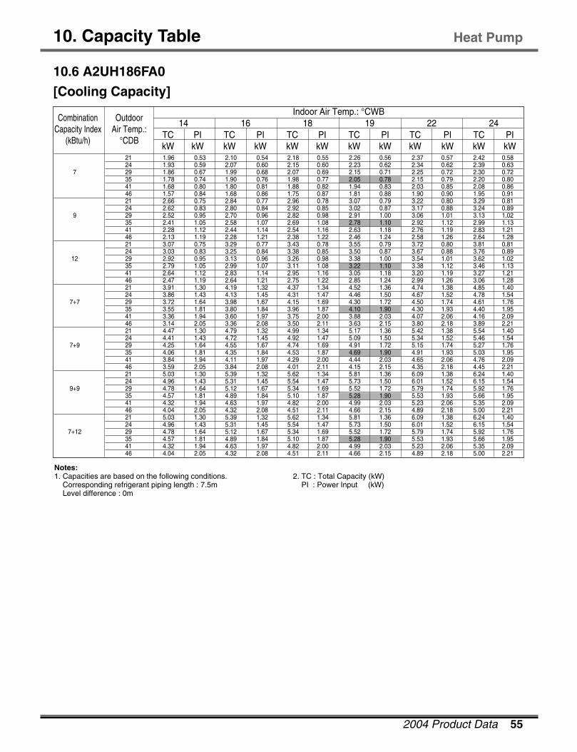
2004 Product Data 55
10. Capacity Table
10.6 A2UH186FA0
[Cooling Capacity]
Heat Pump
TC PI TC PI TC PI TC PI TC PI TC PIkW kW kW kW kW kW kW kW kW kW kW kW
CombinationCapacity Index
(kBtu/h)
Outdoor Air Temp.:
°CDB
14 16 18 19 22 24 Indoor Air Temp.: °CWB
21 1.96 0.53 2.10 0.54 2.18 0.55 2.26 0.56 2.37 0.57 2.42 0.58 24 1.93 0.59 2.07 0.60 2.15 0.60 2.23 0.62 2.34 0.62 2.39 0.63
7 29 1.86 0.67 1.99 0.68 2.07 0.69 2.15 0.71 2.25 0.72 2.30 0.72 35 1.78 0.74 1.90 0.76 1.98 0.77 2.05 0.78 2.15 0.79 2.20 0.80 41 1.68 0.80 1.80 0.81 1.88 0.82 1.94 0.83 2.03 0.85 2.08 0.86 46 1.57 0.84 1.68 0.86 1.75 0.87 1.81 0.88 1.90 0.90 1.95 0.91 21 2.66 0.75 2.84 0.77 2.96 0.78 3.07 0.79 3.22 0.80 3.29 0.81 24 2.62 0.83 2.80 0.84 2.92 0.85 3.02 0.87 3.17 0.88 3.24 0.89
9 29 2.52 0.95 2.70 0.96 2.82 0.98 2.91 1.00 3.06 1.01 3.13 1.02 35 2.41 1.05 2.58 1.07 2.69 1.08 2.78 1.10 2.92 1.12 2.99 1.13 41 2.28 1.12 2.44 1.14 2.54 1.16 2.63 1.18 2.76 1.19 2.83 1.21 46 2.13 1.19 2.28 1.21 2.38 1.22 2.46 1.24 2.58 1.26 2.64 1.28 21 3.07 0.75 3.29 0.77 3.43 0.78 3.55 0.79 3.72 0.80 3.81 0.81 24 3.03 0.83 3.25 0.84 3.38 0.85 3.50 0.87 3.67 0.88 3.76 0.89
12 29 2.92 0.95 3.13 0.96 3.26 0.98 3.38 1.00 3.54 1.01 3.62 1.02 35 2.79 1.05 2.99 1.07 3.11 1.08 3.22 1.10 3.38 1.12 3.46 1.13 41 2.64 1.12 2.83 1.14 2.95 1.16 3.05 1.18 3.20 1.19 3.27 1.21 46 2.47 1.19 2.64 1.21 2.75 1.22 2.85 1.24 2.99 1.26 3.06 1.28 21 3.91 1.30 4.19 1.32 4.37 1.34 4.52 1.36 4.74 1.38 4.85 1.40 24 3.86 1.43 4.13 1.45 4.31 1.47 4.46 1.50 4.67 1.52 4.78 1.54
7+7 29 3.72 1.64 3.98 1.67 4.15 1.69 4.30 1.72 4.50 1.74 4.61 1.76 35 3.55 1.81 3.80 1.84 3.96 1.87 4.10 1.90 4.30 1.93 4.40 1.95 41 3.36 1.94 3.60 1.97 3.75 2.00 3.88 2.03 4.07 2.06 4.16 2.09 46 3.14 2.05 3.36 2.08 3.50 2.11 3.63 2.15 3.80 2.18 3.89 2.21 21 4.47 1.30 4.79 1.32 4.99 1.34 5.17 1.36 5.42 1.38 5.54 1.40 24 4.41 1.43 4.72 1.45 4.92 1.47 5.09 1.50 5.34 1.52 5.46 1.54
7+9 29 4.25 1.64 4.55 1.67 4.74 1.69 4.91 1.72 5.15 1.74 5.27 1.76 35 4.06 1.81 4.35 1.84 4.53 1.87 4.69 1.90 4.91 1.93 5.03 1.95 41 3.84 1.94 4.11 1.97 4.29 2.00 4.44 2.03 4.65 2.06 4.76 2.09 46 3.59 2.05 3.84 2.08 4.01 2.11 4.15 2.15 4.35 2.18 4.45 2.21 21 5.03 1.30 5.39 1.32 5.62 1.34 5.81 1.36 6.09 1.38 6.24 1.40 24 4.96 1.43 5.31 1.45 5.54 1.47 5.73 1.50 6.01 1.52 6.15 1.54
9+9 29 4.78 1.64 5.12 1.67 5.34 1.69 5.52 1.72 5.79 1.74 5.92 1.76 35 4.57 1.81 4.89 1.84 5.10 1.87 5.28 1.90 5.53 1.93 5.66 1.95 41 4.32 1.94 4.63 1.97 4.82 2.00 4.99 2.03 5.23 2.06 5.35 2.09 46 4.04 2.05 4.32 2.08 4.51 2.11 4.66 2.15 4.89 2.18 5.00 2.21 21 5.03 1.30 5.39 1.32 5.62 1.34 5.81 1.36 6.09 1.38 6.24 1.40 24 4.96 1.43 5.31 1.45 5.54 1.47 5.73 1.50 6.01 1.52 6.15 1.54
7+12 29 4.78 1.64 5.12 1.67 5.34 1.69 5.52 1.72 5.79 1.74 5.92 1.76 35 4.57 1.81 4.89 1.84 5.10 1.87 5.28 1.90 5.53 1.93 5.66 1.95 41 4.32 1.94 4.63 1.97 4.82 2.00 4.99 2.03 5.23 2.06 5.35 2.09 46 4.04 2.05 4.32 2.08 4.51 2.11 4.66 2.15 4.89 2.18 5.00 2.21
Notes:1. Capacities are based on the following conditions.
Corresponding refrigerant piping length : 7.5mLevel difference : 0m
2. TC : Total Capacity (kW)PI : Power Input (kW)
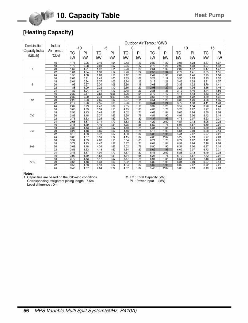
56 MPS Variable Multi Split System(50Hz, R410A)
10. Capacity Table
[Heating Capacity]
TC PI TC PI TC PI TC PI TC PI TC PIkW kW kW kW kW kW kW kW kW kW kW kW
CombinationCapacity Index
(kBtu/h)
IndoorAir Temp.:
°CDB
-10 -5 0 6 10 15Outdoor Air Temp.: °CWB
16 1.78 0.95 2.10 1.04 2.43 1.13 2.82 1.22 3.06 1.28 3.37 1.37 18 1.72 0.98 2.03 1.07 2.35 1.17 2.73 1.26 2.96 1.33 3.27 1.42
7 20 1.67 1.01 1.97 1.11 2.28 1.20 2.64 1.30 2.87 1.37 3.17 1.47 22 1.61 1.04 1.90 1.14 2.20 1.24 2.56 1.34 2.77 1.41 3.05 1.51 24 1.56 1.08 1.83 1.18 2.12 1.28 2.47 1.38 2.67 1.46 2.95 1.56 16 2.08 0.91 2.45 1.00 2.83 1.08 3.29 1.17 3.56 1.23 3.93 1.32 18 2.01 0.94 2.37 1.03 2.74 1.12 3.19 1.21 3.45 1.28 3.81 1.37
9 20 1.95 0.97 2.30 1.06 2.66 1.16 3.08 1.25 3.35 1.32 3.70 1.41 22 1.88 1.00 2.22 1.10 2.56 1.20 2.98 1.29 3.23 1.36 3.56 1.46 24 1.82 1.04 2.14 1.13 2.48 1.23 2.88 1.33 3.12 1.40 3.44 1.50 16 2.39 0.87 2.82 0.96 3.26 1.04 3.79 1.12 4.11 1.18 4.53 1.27 18 2.32 0.90 2.73 0.99 3.16 1.08 3.67 1.16 3.98 1.22 4.39 1.31
12 20 2.25 0.93 2.65 1.02 3.07 1.11 3.54 1.20 3.86 1.26 4.26 1.35 22 2.17 0.96 2.55 1.05 2.96 1.15 3.44 1.24 3.72 1.30 4.11 1.40 24 2.09 0.99 2.47 1.09 2.85 1.18 3.32 1.28 3.59 1.34 3.96 1.44 16 3.05 1.39 3.59 1.51 4.15 1.65 4.83 1.78 5.23 1.87 5.77 2.01 18 2.95 1.43 3.48 1.57 4.02 1.71 4.68 1.84 5.06 1.94 5.59 2.08
7+7 20 2.86 1.48 3.37 1.62 3.90 1.76 4.51 1.90 4.91 2.00 5.42 2.14 22 2.76 1.53 3.25 1.67 3.76 1.82 4.37 1.96 4.73 2.07 5.23 2.21 24 2.66 1.57 3.14 1.72 3.63 1.87 4.22 2.02 4.57 2.13 5.05 2.28 16 3.48 1.39 4.10 1.51 4.75 1.65 5.52 1.78 5.97 1.87 6.59 2.01 18 3.37 1.43 3.97 1.57 4.60 1.71 5.34 1.84 5.79 1.94 6.39 2.08
7+9 20 3.27 1.48 3.85 1.62 4.46 1.76 5.16 1.90 5.61 2.00 6.20 2.14 22 3.15 1.53 3.72 1.67 4.30 1.82 5.00 1.96 5.41 2.07 5.97 2.21 24 3.05 1.57 3.59 1.72 4.15 1.87 4.83 2.02 5.22 2.13 5.77 2.28 16 3.92 1.39 4.62 1.51 5.34 1.65 6.21 1.78 6.72 1.87 7.42 2.01 18 3.79 1.43 4.47 1.57 5.17 1.71 6.01 1.84 6.51 1.94 7.18 2.08
9+9 20 3.68 1.48 4.34 1.62 5.02 1.76 5.80 1.90 6.31 2.00 6.97 2.14 22 3.55 1.53 4.18 1.67 4.84 1.82 5.62 1.96 6.09 2.07 6.72 2.21 24 3.43 1.57 4.04 1.72 4.67 1.87 5.43 2.02 5.88 2.13 6.49 2.28 16 3.92 1.39 4.62 1.51 5.34 1.65 6.21 1.78 6.72 1.87 7.42 2.01 18 3.79 1.43 4.47 1.57 5.17 1.71 6.01 1.84 6.51 1.94 7.18 2.08
7+12 20 3.68 1.48 4.34 1.62 5.02 1.76 5.80 1.90 6.31 2.00 6.97 2.14 22 3.55 1.53 4.18 1.67 4.84 1.82 5.62 1.96 6.09 2.07 6.72 2.21 24 3.43 1.57 4.04 1.72 4.67 1.87 5.43 2.02 5.88 2.13 6.49 2.28
Notes:1. Capacities are based on the following conditions.
Corresponding refrigerant piping length : 7.5mLevel difference : 0m
2. TC : Total Capacity (kW)PI : Power Input (kW)
Heat Pump
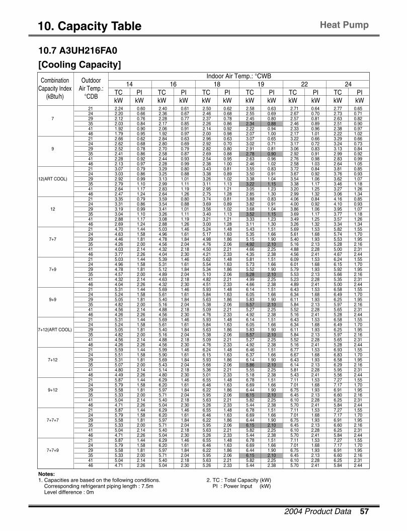
2004 Product Data 57
10. Capacity Table Heat Pump
10.7 A3UH216FA0
[Cooling Capacity]
TC PI TC PI TC PI TC PI TC PI TC PIkW kW kW kW kW kW kW kW kW kW kW kW
CombinationCapacity Index
(kBtu/h)
Outdoor Air Temp.:
°CDB
14 16 18 19 22 24 Indoor Air Temp.: °CWB
21 2.24 0.60 2.40 0.61 2.50 0.62 2.58 0.63 2.71 0.64 2.77 0.65 24 2.20 0.66 2.36 0.67 2.46 0.68 2.55 0.69 2.67 0.70 2.73 0.71
7 29 2.12 0.76 2.28 0.77 2.37 0.78 2.45 0.80 2.57 0.81 2.63 0.82 35 2.03 0.84 2.17 0.85 2.26 0.86 2.34 0.88 2.46 0.89 2.51 0.90 41 1.92 0.90 2.06 0.91 2.14 0.92 2.22 0.94 2.33 0.96 2.38 0.97 46 1.79 0.95 1.92 0.97 2.00 0.98 2.07 1.00 2.17 1.01 2.22 1.02 21 2.66 0.62 2.84 0.63 2.96 0.63 3.07 0.65 3.22 0.66 3.29 0.66 24 2.62 0.68 2.80 0.69 2.92 0.70 3.02 0.71 3.17 0.72 3.24 0.73
9 29 2.52 0.78 2.70 0.79 2.82 0.80 2.91 0.81 3.06 0.83 3.13 0.84 35 2.41 0.86 2.58 0.87 2.69 0.88 2.78 0.90 2.92 0.91 2.99 0.92 41 2.28 0.92 2.44 0.93 2.54 0.95 2.63 0.96 2.76 0.98 2.83 0.99 46 2.13 0.97 2.28 0.99 2.38 1.00 2.46 1.02 2.58 1.03 2.64 1.05 21 3.07 0.79 3.29 0.80 3.43 0.81 3.55 0.83 3.72 0.84 3.81 0.85 24 3.03 0.86 3.25 0.88 3.38 0.89 3.50 0.91 3.67 0.92 3.76 0.93
12(ART COOL) 29 2.92 0.99 3.13 1.01 3.26 1.02 3.38 1.04 3.54 1.06 3.62 1.07 35 2.79 1.10 2.99 1.11 3.11 1.13 3.22 1.15 3.38 1.17 3.46 1.18 41 2.64 1.17 2.83 1.19 2.95 1.21 3.05 1.23 3.20 1.25 3.27 1.26 46 2.47 1.24 2.64 1.26 2.75 1.28 2.85 1.30 2.99 1.32 3.06 1.34 21 3.35 0.79 3.59 0.80 3.74 0.81 3.88 0.83 4.06 0.84 4.16 0.85 24 3.31 0.86 3.54 0.88 3.69 0.89 3.82 0.91 4.00 0.92 4.10 0.93
12 29 3.19 0.99 3.41 1.01 3.56 1.02 3.68 1.04 3.86 1.06 3.95 1.07 35 3.04 1.10 3.26 1.11 3.40 1.13 3.52 1.15 3.69 1.17 3.77 1.18 41 2.88 1.17 3.08 1.19 3.21 1.21 3.33 1.23 3.49 1.25 3.57 1.26 46 2.69 1.24 2.88 1.26 3.00 1.28 3.11 1.30 3.26 1.32 3.34 1.34 21 4.70 1.44 5.03 1.46 5.24 1.48 5.43 1.51 5.69 1.53 5.82 1.55 24 4.63 1.58 4.96 1.61 5.17 1.63 5.35 1.66 5.61 1.68 5.74 1.70
7+7 29 4.46 1.81 4.78 1.84 4.98 1.86 5.15 1.90 5.40 1.93 5.53 1.95 35 4.26 2.00 4.56 2.04 4.76 2.06 4.92 2.10 5.16 2.13 5.28 2.16 41 4.03 2.14 4.32 2.18 4.50 2.21 4.66 2.25 4.88 2.28 5.00 2.31 46 3.77 2.26 4.04 2.30 4.21 2.33 4.35 2.38 4.56 2.41 4.67 2.44 21 5.03 1.44 5.39 1.46 5.62 1.48 5.81 1.51 6.09 1.53 6.24 1.55 24 4.96 1.58 5.31 1.61 5.54 1.63 5.73 1.66 6.01 1.68 6.15 1.70
7+9 29 4.78 1.81 5.12 1.84 5.34 1.86 5.52 1.90 5.79 1.93 5.92 1.95 35 4.57 2.00 4.89 2.04 5.10 2.06 5.28 2.10 5.53 2.13 5.66 2.16 41 4.32 2.14 4.63 2.18 4.82 2.21 4.99 2.25 5.23 2.28 5.35 2.31 46 4.04 2.26 4.32 2.30 4.51 2.33 4.66 2.38 4.89 2.41 5.00 2.44 21 5.31 1.44 5.69 1.46 5.93 1.48 6.14 1.51 6.43 1.53 6.58 1.55 24 5.24 1.58 5.61 1.61 5.84 1.63 6.05 1.66 6.34 1.68 6.49 1.70
9+9 29 5.05 1.81 5.40 1.84 5.63 1.86 5.83 1.90 6.11 1.93 6.25 1.95 35 4.82 2.00 5.16 2.04 5.38 2.06 5.57 2.10 5.84 2.13 5.97 2.16 41 4.56 2.14 4.88 2.18 5.09 2.21 5.27 2.25 5.52 2.28 5.65 2.31 46 4.26 2.26 4.56 2.30 4.76 2.33 4.92 2.38 5.16 2.41 5.28 2.44 21 5.31 1.44 5.69 1.46 5.93 1.48 6.14 1.51 6.43 1.53 6.58 1.55 24 5.24 1.58 5.61 1.61 5.84 1.63 6.05 1.66 6.34 1.68 6.49 1.70
7+12(ART COOL) 29 5.05 1.81 5.40 1.84 5.63 1.86 5.83 1.90 6.11 1.93 6.25 1.95 35 4.82 2.00 5.16 2.04 5.38 2.06 5.57 2.10 5.84 2.13 5.97 2.16 41 4.56 2.14 4.88 2.18 5.09 2.21 5.27 2.25 5.52 2.28 5.65 2.31 46 4.26 2.26 4.56 2.30 4.76 2.33 4.92 2.38 5.16 2.41 5.28 2.44 21 5.59 1.44 5.99 1.46 6.24 1.48 6.46 1.51 6.77 1.53 6.93 1.55 24 5.51 1.58 5.90 1.61 6.15 1.63 6.37 1.66 6.67 1.68 6.83 1.70
7+12 29 5.31 1.81 5.69 1.84 5.93 1.86 6.14 1.90 6.43 1.93 6.58 1.95 35 5.07 2.00 5.43 2.04 5.66 2.06 5.86 2.10 6.14 2.13 6.29 2.16 41 4.80 2.14 5.14 2.18 5.36 2.21 5.55 2.25 5.81 2.28 5.95 2.31 46 4.49 2.26 4.80 2.30 5.01 2.33 5.18 2.38 5.43 2.41 5.56 2.44 21 5.87 1.44 6.29 1.46 6.55 1.48 6.78 1.51 7.11 1.53 7.27 1.55 24 5.79 1.58 6.20 1.61 6.46 1.63 6.69 1.66 7.01 1.68 7.17 1.70
9+12 29 5.58 1.81 5.97 1.84 6.22 1.86 6.44 1.90 6.75 1.93 6.91 1.95 35 5.33 2.00 5.71 2.04 5.95 2.06 6.15 2.10 6.45 2.13 6.60 2.16 41 5.04 2.14 5.40 2.18 5.63 2.21 5.82 2.25 6.10 2.28 6.25 2.31 46 4.71 2.26 5.04 2.30 5.26 2.33 5.44 2.38 5.70 2.41 5.84 2.44 21 5.87 1.44 6.29 1.46 6.55 1.48 6.78 1.51 7.11 1.53 7.27 1.55 24 5.79 1.58 6.20 1.61 6.46 1.63 6.69 1.66 7.01 1.68 7.17 1.70
7+7+7 29 5.58 1.81 5.97 1.84 6.22 1.86 6.44 1.90 6.75 1.93 6.91 1.95 35 5.33 2.00 5.71 2.04 5.95 2.06 6.15 2.10 6.45 2.13 6.60 2.16 41 5.04 2.14 5.40 2.18 5.63 2.21 5.82 2.25 6.10 2.28 6.25 2.31 46 4.71 2.26 5.04 2.30 5.26 2.33 5.44 2.38 5.70 2.41 5.84 2.44 21 5.87 1.44 6.29 1.46 6.55 1.48 6.78 1.51 7.11 1.53 7.27 1.55 24 5.79 1.58 6.20 1.61 6.46 1.63 6.69 1.66 7.01 1.68 7.17 1.70
7+7+9 29 5.58 1.81 5.97 1.84 6.22 1.86 6.44 1.90 6.75 1.93 6.91 1.95 35 5.33 2.00 5.71 2.04 5.95 2.06 6.15 2.10 6.45 2.13 6.60 2.16 41 5.04 2.14 5.40 2.18 5.63 2.21 5.82 2.25 6.10 2.28 6.25 2.31 46 4.71 2.26 5.04 2.30 5.26 2.33 5.44 2.38 5.70 2.41 5.84 2.44
Notes:1. Capacities are based on the following conditions.
Corresponding refrigerant piping length : 7.5mLevel difference : 0m
2. TC : Total Capacity (kW)PI : Power Input (kW)
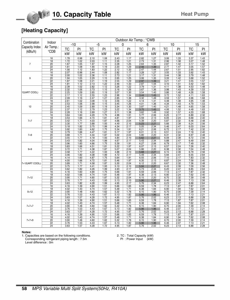
58 MPS Variable Multi Split System(50Hz, R410A)
10. Capacity Table
[Heating Capacity]
TC PI TC PI TC PI TC PI TC PI TC PIkW kW kW kW kW kW kW kW kW kW kW kW
CombinationCapacity Index
(kBtu/h)
Indoor Air Temp.:
°CDB
-10 -5 0 6 10 15Outdoor Air Temp.: °CWB
16 1.78 0.98 2.10 1.08 2.43 1.17 2.82 1.27 3.06 1.33 3.37 1.43 18 1.72 1.02 2.03 1.11 2.35 1.21 2.73 1.31 2.96 1.38 3.27 1.48
7 20 1.67 1.05 1.97 1.15 2.28 1.25 2.64 1.35 2.87 1.42 3.17 1.52 22 1.61 1.08 1.90 1.19 2.20 1.29 2.56 1.39 2.77 1.47 3.05 1.57 24 1.56 1.12 1.83 1.22 2.12 1.33 2.47 1.44 2.67 1.51 2.95 1.62 16 2.07 0.98 2.44 1.08 2.82 1.17 3.28 1.27 3.55 1.33 3.92 1.43 18 2.00 1.02 2.36 1.11 2.73 1.21 3.17 1.31 3.44 1.38 3.79 1.48
9 20 1.94 1.05 2.29 1.15 2.65 1.25 3.06 1.35 3.33 1.42 3.68 1.52 22 1.87 1.08 2.21 1.19 2.55 1.29 2.97 1.39 3.21 1.47 3.55 1.57 24 1.81 1.12 2.13 1.22 2.46 1.33 2.87 1.44 3.10 1.51 3.42 1.62 16 2.39 1.02 2.82 1.12 3.26 1.22 3.79 1.31 4.11 1.38 4.53 1.48 18 2.32 1.06 2.73 1.15 3.16 1.26 3.67 1.36 3.98 1.43 4.39 1.53
12(ART COOL) 20 2.25 1.09 2.65 1.19 3.07 1.30 3.54 1.40 3.86 1.48 4.26 1.58 22 2.17 1.12 2.55 1.23 2.96 1.34 3.44 1.45 3.72 1.52 4.11 1.63 24 2.09 1.16 2.47 1.27 2.85 1.38 3.32 1.49 3.59 1.57 3.96 1.68 16 2.61 1.02 3.08 1.12 3.56 1.22 4.14 1.31 4.48 1.38 4.95 1.48 18 2.53 1.06 2.98 1.15 3.45 1.26 4.01 1.36 4.34 1.43 4.79 1.53
12 20 2.45 1.09 2.89 1.19 3.34 1.30 3.87 1.40 4.21 1.48 4.65 1.58 22 2.37 1.12 2.79 1.23 3.22 1.34 3.75 1.45 4.06 1.52 4.48 1.63 24 2.28 1.16 2.69 1.27 3.11 1.38 3.62 1.49 3.92 1.57 4.33 1.68 16 3.64 1.60 4.29 1.75 4.96 1.91 5.77 2.06 6.25 2.17 6.89 2.32 18 3.53 1.66 4.15 1.81 4.81 1.97 5.59 2.13 6.05 2.24 6.68 2.40
7+7 20 3.42 1.71 4.03 1.87 4.66 2.04 5.39 2.20 5.87 2.32 6.48 2.48 22 3.30 1.77 3.88 1.93 4.49 2.10 5.23 2.27 5.66 2.39 6.24 2.56 24 3.18 1.82 3.75 1.99 4.34 2.17 5.05 2.34 5.46 2.47 6.03 2.64 16 3.92 1.60 4.62 1.75 5.34 1.91 6.21 2.06 6.72 2.17 7.42 2.32 18 3.79 1.66 4.47 1.81 5.17 1.97 6.01 2.13 6.51 2.24 7.18 2.40
7+9 20 3.68 1.71 4.34 1.87 5.02 2.04 5.80 2.20 6.31 2.32 6.97 2.48 22 3.55 1.77 4.18 1.93 4.84 2.10 5.62 2.27 6.09 2.39 6.72 2.56 24 3.43 1.82 4.04 1.99 4.67 2.17 5.43 2.34 5.88 2.47 6.49 2.64 16 3.96 1.60 4.66 1.75 5.39 1.91 6.27 2.06 6.79 2.17 7.49 2.32 18 3.83 1.66 4.51 1.81 5.22 1.97 6.07 2.13 6.57 2.24 7.26 2.40
9+9 20 3.72 1.71 4.38 1.87 5.07 2.04 5.86 2.20 6.38 2.32 7.04 2.48 22 3.58 1.77 4.22 1.93 4.88 2.10 5.68 2.27 6.15 2.39 6.79 2.56 24 3.46 1.82 4.08 1.99 4.72 2.17 5.49 2.34 5.94 2.47 6.55 2.64 16 4.14 1.60 4.87 1.75 5.64 1.91 6.55 2.06 7.10 2.17 7.83 2.32 18 4.00 1.66 4.72 1.81 5.46 1.97 6.35 2.13 6.87 2.24 7.58 2.40
7+12(ART COOL) 20 3.89 1.71 4.58 1.87 5.30 2.04 6.12 2.20 6.67 2.32 7.36 2.48 22 3.75 1.77 4.41 1.93 5.10 2.10 5.94 2.27 6.43 2.39 7.09 2.56 24 3.62 1.82 4.26 1.99 4.93 2.17 5.73 2.34 6.20 2.47 6.85 2.64 16 4.16 1.60 4.90 1.75 5.66 1.91 6.59 2.06 7.13 2.17 7.87 2.32 18 4.02 1.66 4.74 1.81 5.48 1.97 6.38 2.13 6.90 2.24 7.62 2.40
7+12 20 3.90 1.71 4.60 1.87 5.32 2.04 6.15 2.20 6.70 2.32 7.39 2.48 22 3.76 1.77 4.43 1.93 5.13 2.10 5.96 2.27 6.46 2.39 7.13 2.56 24 3.63 1.82 4.28 1.99 4.95 2.17 5.76 2.34 6.23 2.47 6.88 2.64 16 4.16 1.39 4.90 1.51 5.66 1.65 6.59 1.78 7.13 1.87 7.87 2.01 18 4.02 1.43 4.74 1.57 5.48 1.71 6.38 1.84 6.90 1.94 7.62 2.08
9+12 20 3.90 1.48 4.60 1.62 5.32 1.76 6.15 1.90 6.70 2.00 7.39 2.14 22 3.76 1.53 4.43 1.67 5.13 1.82 5.96 1.96 6.46 2.07 7.13 2.21 24 3.63 1.57 4.28 1.72 4.95 1.87 5.76 2.02 6.23 2.13 6.88 2.28 16 4.16 1.39 4.90 1.51 5.66 1.65 6.59 1.78 7.13 1.87 7.87 2.01 18 4.02 1.43 4.74 1.57 5.48 1.71 6.38 1.84 6.90 1.94 7.62 2.08
7+7+7 20 3.90 1.48 4.60 1.62 5.32 1.76 6.15 1.90 6.70 2.00 7.39 2.14 22 3.76 1.53 4.43 1.67 5.13 1.82 5.96 1.96 6.46 2.07 7.13 2.21 24 3.63 1.57 4.28 1.72 4.95 1.87 5.76 2.02 6.23 2.13 6.88 2.28 16 4.16 1.39 4.90 1.51 5.66 1.65 6.59 1.78 7.13 1.87 7.87 2.01 18 4.02 1.43 4.74 1.57 5.48 1.71 6.38 1.84 6.90 1.94 7.62 2.08
7+7+9 20 3.90 1.48 4.60 1.62 5.32 1.76 6.15 1.90 6.70 2.00 7.39 2.14 22 3.76 1.53 4.43 1.67 5.13 1.82 5.96 1.96 6.46 2.07 7.13 2.21 24 3.63 1.57 4.28 1.72 4.95 1.87 5.76 2.02 6.23 2.13 6.88 2.28
Notes:1. Capacities are based on the following conditions.
Corresponding refrigerant piping length : 7.5mLevel difference : 0m
2. TC : Total Capacity (kW)PI : Power Input (kW)
Heat Pump
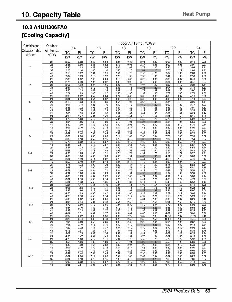
2004 Product Data 59
10. Capacity Table
10.8 A4UH306FA0
[Cooling Capacity]
TC PI TC PI TC PI TC PI TC PI TC PIkW kW kW kW kW kW kW kW kW kW kW kW
CombinationCapacity Index
(kBtu/h)
Outdoor Air Temp.:
°CDB
14 16 18 19 22 24 Indoor Air Temp.: °CWB
21 2.52 0.82 2.69 0.84 2.81 0.85 2.91 0.86 3.05 0.87 3.12 0.88 24 2.48 0.90 2.66 0.92 2.77 0.93 2.87 0.95 3.00 0.96 3.07 0.97
7 29 2.39 1.03 2.56 1.05 2.67 1.07 2.76 1.09 2.89 1.10 2.96 1.11 35 2.28 1.14 2.45 1.16 2.55 1.18 2.64 1.20 2.76 1.22 2.83 1.23 41 2.16 1.22 2.31 1.25 2.41 1.26 2.50 1.28 2.62 1.30 2.68 1.32 46 2.02 1.29 2.16 1.32 2.25 1.33 2.33 1.36 2.44 1.38 2.50 1.39 21 2.80 0.82 2.99 0.84 3.12 0.85 3.23 0.86 3.39 0.87 3.46 0.88 24 2.76 0.90 2.95 0.92 3.08 0.93 3.18 0.95 3.34 0.96 3.41 0.97
9 29 2.66 1.03 2.84 1.05 2.96 1.07 3.07 1.09 3.22 1.10 3.29 1.11 35 2.54 1.14 2.72 1.16 2.83 1.18 2.93 1.20 3.07 1.22 3.14 1.23 41 2.40 1.22 2.57 1.25 2.68 1.26 2.77 1.28 2.91 1.30 2.97 1.32 46 2.24 1.29 2.40 1.32 2.50 1.33 2.59 1.36 2.72 1.38 2.78 1.39 21 3.35 0.82 3.59 0.84 3.74 0.85 3.88 0.86 4.06 0.87 4.16 0.88 24 3.31 0.90 3.54 0.92 3.69 0.93 3.82 0.95 4.00 0.96 4.10 0.97
12 29 3.19 1.03 3.41 1.05 3.56 1.07 3.68 1.09 3.86 1.10 3.95 1.11 35 3.04 1.14 3.26 1.16 3.40 1.18 3.52 1.20 3.69 1.22 3.77 1.23 41 2.88 1.22 3.08 1.25 3.21 1.26 3.33 1.28 3.49 1.30 3.57 1.32 46 2.69 1.29 2.88 1.32 3.00 1.33 3.11 1.36 3.26 1.38 3.34 1.39 21 5.03 1.33 5.39 1.36 5.62 1.37 5.81 1.40 6.09 1.42 6.24 1.44 24 4.96 1.47 5.31 1.49 5.54 1.51 5.73 1.54 6.01 1.56 6.15 1.58
18 29 4.78 1.68 5.12 1.71 5.34 1.73 5.52 1.76 5.79 1.79 5.92 1.81 35 4.57 1.86 4.89 1.89 5.10 1.91 5.28 1.95 5.53 1.98 5.66 2.00 41 4.32 1.99 4.63 2.02 4.82 2.05 4.99 2.09 5.23 2.12 5.35 2.14 46 4.04 2.10 4.32 2.14 4.51 2.17 4.66 2.21 4.89 2.24 5.00 2.27 21 6.71 2.22 7.19 2.26 7.49 2.29 7.75 2.33 8.12 2.37 8.31 2.40 24 6.61 2.44 7.08 2.48 7.38 2.52 7.64 2.56 8.01 2.60 8.20 2.63
24 29 6.37 2.80 6.83 2.85 7.11 2.89 7.36 2.94 7.72 2.98 7.90 3.02 35 6.09 3.10 6.52 3.15 6.79 3.19 7.03 3.25 7.37 3.30 7.54 3.34 41 5.76 3.32 6.17 3.37 6.43 3.42 6.65 3.48 6.98 3.53 7.14 3.57 46 5.38 3.51 5.77 3.57 6.01 3.61 6.22 3.68 6.52 3.73 6.67 3.78 21 4.47 1.33 4.79 1.36 4.99 1.37 5.17 1.40 5.42 1.42 5.54 1.44 24 4.41 1.47 4.72 1.49 4.92 1.51 5.09 1.54 5.34 1.56 5.46 1.58
7+7 29 4.25 1.68 4.55 1.71 4.74 1.73 4.91 1.76 5.15 1.79 5.27 1.81 35 4.06 1.86 4.35 1.89 4.53 1.91 4.69 1.95 4.91 1.98 5.03 2.00 41 3.84 1.99 4.11 2.02 4.29 2.05 4.44 2.09 4.65 2.12 4.76 2.14 46 3.59 2.10 3.84 2.14 4.01 2.17 4.15 2.21 4.35 2.24 4.45 2.27 21 4.75 1.33 5.09 1.36 5.30 1.37 5.49 1.40 5.75 1.42 5.89 1.44 24 4.68 1.47 5.02 1.49 5.23 1.51 5.41 1.54 5.67 1.56 5.81 1.58
7+9 29 4.51 1.68 4.84 1.71 5.04 1.73 5.22 1.76 5.47 1.79 5.59 1.81 35 4.31 1.86 4.62 1.89 4.81 1.91 4.98 1.95 5.22 1.98 5.34 2.00 41 4.08 1.99 4.37 2.02 4.55 2.05 4.71 2.09 4.94 2.12 5.06 2.14 46 3.81 2.10 4.08 2.14 4.26 2.17 4.41 2.21 4.62 2.24 4.73 2.27 21 5.31 1.33 5.69 1.36 5.93 1.37 6.14 1.40 6.43 1.42 6.58 1.44 24 5.24 1.47 5.61 1.49 5.84 1.51 6.05 1.54 6.34 1.56 6.49 1.58
7+12 29 5.05 1.68 5.40 1.71 5.63 1.73 5.83 1.76 6.11 1.79 6.25 1.81 35 4.82 1.86 5.16 1.89 5.38 1.91 5.57 1.95 5.84 1.98 5.97 2.00 41 4.56 1.99 4.88 2.02 5.09 2.05 5.27 2.09 5.52 2.12 5.65 2.14 46 4.26 2.10 4.56 2.14 4.76 2.17 4.92 2.21 5.16 2.24 5.28 2.27 21 5.03 2.22 5.39 2.26 5.62 2.29 5.81 2.33 6.09 2.37 6.24 2.40 24 4.96 2.44 5.31 2.48 5.54 2.52 5.73 2.56 6.01 2.60 6.15 2.63
7+18 29 4.78 2.80 5.12 2.85 5.34 2.89 5.52 2.94 5.79 2.98 5.92 3.02 35 4.57 3.10 4.89 3.15 5.10 3.19 5.28 3.25 5.53 3.30 5.66 3.34 41 4.32 3.32 4.63 3.37 4.82 3.42 4.99 3.48 5.23 3.53 5.35 3.57 46 4.04 3.51 4.32 3.57 4.51 3.61 4.66 3.68 4.89 3.73 5.00 3.78 21 8.39 2.22 8.98 2.26 9.36 2.29 9.69 2.33 10.16 2.37 10.39 2.40 24 8.27 2.44 8.85 2.48 9.23 2.52 9.55 2.56 10.01 2.60 10.24 2.63
7+24 29 7.97 2.80 8.53 2.85 8.89 2.89 9.20 2.94 9.65 2.98 9.87 3.02 35 7.61 3.10 8.15 3.15 8.49 3.19 8.79 3.25 9.22 3.30 9.43 3.34 41 7.20 3.32 7.71 3.37 8.04 3.42 8.32 3.48 8.72 3.53 8.92 3.57 46 6.73 3.51 7.21 3.57 7.51 3.61 7.77 3.68 8.15 3.73 8.34 3.78 21 5.03 1.33 5.39 1.36 5.62 1.37 5.81 1.40 6.09 1.42 6.24 1.44 24 4.96 1.47 5.31 1.49 5.54 1.51 5.73 1.54 6.01 1.56 6.15 1.58
9+9 29 4.78 1.68 5.12 1.71 5.34 1.73 5.52 1.76 5.79 1.79 5.92 1.81 35 4.57 1.86 4.89 1.89 5.10 1.91 5.28 1.95 5.53 1.98 5.66 2.00 41 4.32 1.99 4.63 2.02 4.82 2.05 4.99 2.09 5.23 2.12 5.35 2.14 46 4.04 2.10 4.32 2.14 4.51 2.17 4.66 2.21 4.89 2.24 5.00 2.27 21 6.99 2.22 7.48 2.26 7.80 2.29 8.07 2.33 8.46 2.37 8.66 2.40 24 6.89 2.44 7.38 2.48 7.69 2.52 7.96 2.56 8.34 2.60 8.54 2.63
9+12 29 6.64 2.80 7.11 2.85 7.41 2.89 7.67 2.94 8.04 2.98 8.23 3.02 35 6.34 3.10 6.79 3.15 7.08 3.19 7.33 3.25 7.68 3.30 7.86 3.34 41 6.00 3.32 6.43 3.37 6.70 3.42 6.93 3.48 7.27 3.53 7.44 3.57 46 5.61 3.51 6.01 3.57 6.26 3.61 6.48 3.68 6.79 3.73 6.95 3.78
Heat Pump
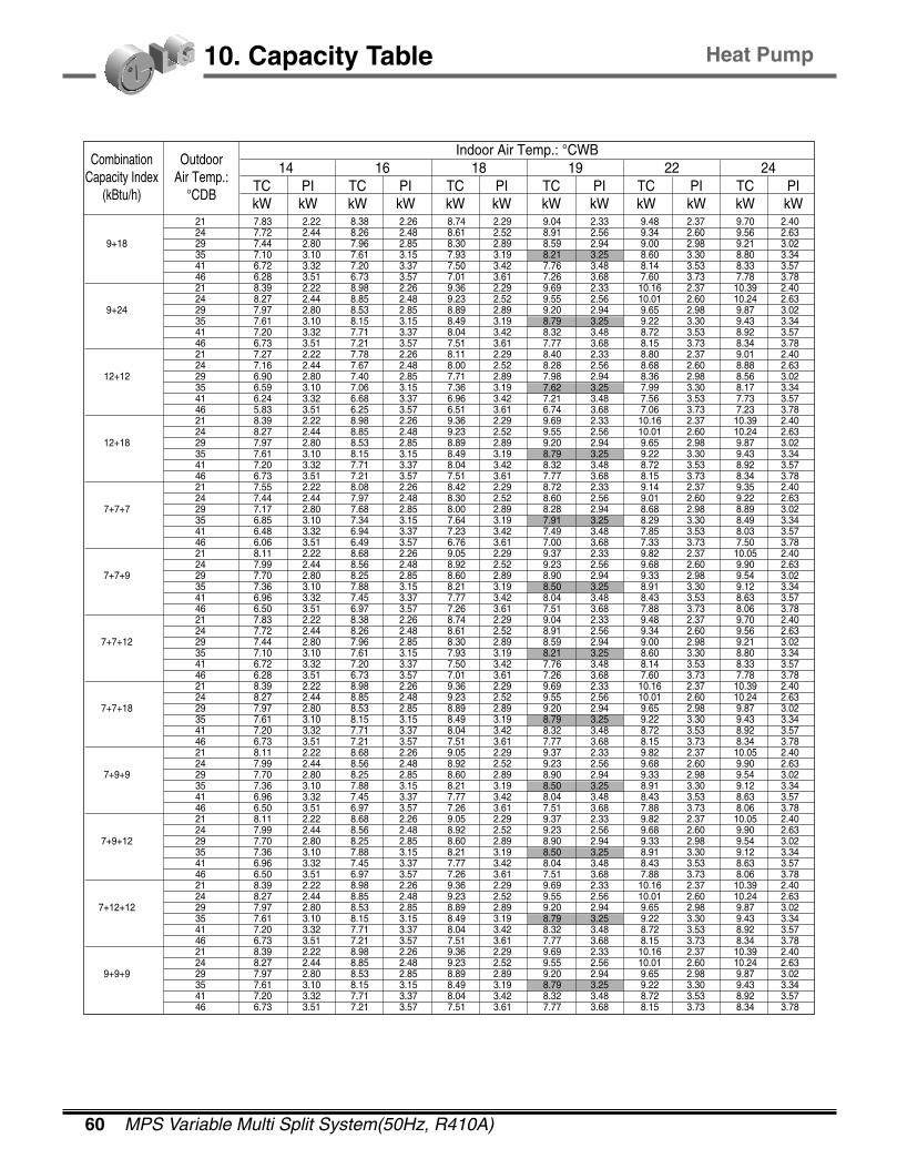
60 MPS Variable Multi Split System(50Hz, R410A)
10. Capacity Table
TC PI TC PI TC PI TC PI TC PI TC PIkW kW kW kW kW kW kW kW kW kW kW kW
CombinationCapacity Index
(kBtu/h)
Outdoor Air Temp.:
°CDB
14 16 18 19 22 24 Indoor Air Temp.: °CWB
21 7.83 2.22 8.38 2.26 8.74 2.29 9.04 2.33 9.48 2.37 9.70 2.40 24 7.72 2.44 8.26 2.48 8.61 2.52 8.91 2.56 9.34 2.60 9.56 2.63
9+18 29 7.44 2.80 7.96 2.85 8.30 2.89 8.59 2.94 9.00 2.98 9.21 3.02 35 7.10 3.10 7.61 3.15 7.93 3.19 8.21 3.25 8.60 3.30 8.80 3.34 41 6.72 3.32 7.20 3.37 7.50 3.42 7.76 3.48 8.14 3.53 8.33 3.57 46 6.28 3.51 6.73 3.57 7.01 3.61 7.26 3.68 7.60 3.73 7.78 3.78 21 8.39 2.22 8.98 2.26 9.36 2.29 9.69 2.33 10.16 2.37 10.39 2.40 24 8.27 2.44 8.85 2.48 9.23 2.52 9.55 2.56 10.01 2.60 10.24 2.63
9+24 29 7.97 2.80 8.53 2.85 8.89 2.89 9.20 2.94 9.65 2.98 9.87 3.02 35 7.61 3.10 8.15 3.15 8.49 3.19 8.79 3.25 9.22 3.30 9.43 3.34 41 7.20 3.32 7.71 3.37 8.04 3.42 8.32 3.48 8.72 3.53 8.92 3.57 46 6.73 3.51 7.21 3.57 7.51 3.61 7.77 3.68 8.15 3.73 8.34 3.78 21 7.27 2.22 7.78 2.26 8.11 2.29 8.40 2.33 8.80 2.37 9.01 2.40 24 7.16 2.44 7.67 2.48 8.00 2.52 8.28 2.56 8.68 2.60 8.88 2.63
12+12 29 6.90 2.80 7.40 2.85 7.71 2.89 7.98 2.94 8.36 2.98 8.56 3.02 35 6.59 3.10 7.06 3.15 7.36 3.19 7.62 3.25 7.99 3.30 8.17 3.34 41 6.24 3.32 6.68 3.37 6.96 3.42 7.21 3.48 7.56 3.53 7.73 3.57 46 5.83 3.51 6.25 3.57 6.51 3.61 6.74 3.68 7.06 3.73 7.23 3.78 21 8.39 2.22 8.98 2.26 9.36 2.29 9.69 2.33 10.16 2.37 10.39 2.40 24 8.27 2.44 8.85 2.48 9.23 2.52 9.55 2.56 10.01 2.60 10.24 2.63
12+18 29 7.97 2.80 8.53 2.85 8.89 2.89 9.20 2.94 9.65 2.98 9.87 3.02 35 7.61 3.10 8.15 3.15 8.49 3.19 8.79 3.25 9.22 3.30 9.43 3.34 41 7.20 3.32 7.71 3.37 8.04 3.42 8.32 3.48 8.72 3.53 8.92 3.57 46 6.73 3.51 7.21 3.57 7.51 3.61 7.77 3.68 8.15 3.73 8.34 3.78 21 7.55 2.22 8.08 2.26 8.42 2.29 8.72 2.33 9.14 2.37 9.35 2.40 24 7.44 2.44 7.97 2.48 8.30 2.52 8.60 2.56 9.01 2.60 9.22 2.63
7+7+7 29 7.17 2.80 7.68 2.85 8.00 2.89 8.28 2.94 8.68 2.98 8.89 3.02 35 6.85 3.10 7.34 3.15 7.64 3.19 7.91 3.25 8.29 3.30 8.49 3.34 41 6.48 3.32 6.94 3.37 7.23 3.42 7.49 3.48 7.85 3.53 8.03 3.57 46 6.06 3.51 6.49 3.57 6.76 3.61 7.00 3.68 7.33 3.73 7.50 3.78 21 8.11 2.22 8.68 2.26 9.05 2.29 9.37 2.33 9.82 2.37 10.05 2.40 24 7.99 2.44 8.56 2.48 8.92 2.52 9.23 2.56 9.68 2.60 9.90 2.63
7+7+9 29 7.70 2.80 8.25 2.85 8.60 2.89 8.90 2.94 9.33 2.98 9.54 3.02 35 7.36 3.10 7.88 3.15 8.21 3.19 8.50 3.25 8.91 3.30 9.12 3.34 41 6.96 3.32 7.45 3.37 7.77 3.42 8.04 3.48 8.43 3.53 8.63 3.57 46 6.50 3.51 6.97 3.57 7.26 3.61 7.51 3.68 7.88 3.73 8.06 3.78 21 7.83 2.22 8.38 2.26 8.74 2.29 9.04 2.33 9.48 2.37 9.70 2.40 24 7.72 2.44 8.26 2.48 8.61 2.52 8.91 2.56 9.34 2.60 9.56 2.63
7+7+12 29 7.44 2.80 7.96 2.85 8.30 2.89 8.59 2.94 9.00 2.98 9.21 3.02 35 7.10 3.10 7.61 3.15 7.93 3.19 8.21 3.25 8.60 3.30 8.80 3.34 41 6.72 3.32 7.20 3.37 7.50 3.42 7.76 3.48 8.14 3.53 8.33 3.57 46 6.28 3.51 6.73 3.57 7.01 3.61 7.26 3.68 7.60 3.73 7.78 3.78 21 8.39 2.22 8.98 2.26 9.36 2.29 9.69 2.33 10.16 2.37 10.39 2.40 24 8.27 2.44 8.85 2.48 9.23 2.52 9.55 2.56 10.01 2.60 10.24 2.63
7+7+18 29 7.97 2.80 8.53 2.85 8.89 2.89 9.20 2.94 9.65 2.98 9.87 3.02 35 7.61 3.10 8.15 3.15 8.49 3.19 8.79 3.25 9.22 3.30 9.43 3.34 41 7.20 3.32 7.71 3.37 8.04 3.42 8.32 3.48 8.72 3.53 8.92 3.57 46 6.73 3.51 7.21 3.57 7.51 3.61 7.77 3.68 8.15 3.73 8.34 3.78 21 8.11 2.22 8.68 2.26 9.05 2.29 9.37 2.33 9.82 2.37 10.05 2.40 24 7.99 2.44 8.56 2.48 8.92 2.52 9.23 2.56 9.68 2.60 9.90 2.63
7+9+9 29 7.70 2.80 8.25 2.85 8.60 2.89 8.90 2.94 9.33 2.98 9.54 3.02 35 7.36 3.10 7.88 3.15 8.21 3.19 8.50 3.25 8.91 3.30 9.12 3.34 41 6.96 3.32 7.45 3.37 7.77 3.42 8.04 3.48 8.43 3.53 8.63 3.57 46 6.50 3.51 6.97 3.57 7.26 3.61 7.51 3.68 7.88 3.73 8.06 3.78 21 8.11 2.22 8.68 2.26 9.05 2.29 9.37 2.33 9.82 2.37 10.05 2.40 24 7.99 2.44 8.56 2.48 8.92 2.52 9.23 2.56 9.68 2.60 9.90 2.63
7+9+12 29 7.70 2.80 8.25 2.85 8.60 2.89 8.90 2.94 9.33 2.98 9.54 3.02 35 7.36 3.10 7.88 3.15 8.21 3.19 8.50 3.25 8.91 3.30 9.12 3.34 41 6.96 3.32 7.45 3.37 7.77 3.42 8.04 3.48 8.43 3.53 8.63 3.57 46 6.50 3.51 6.97 3.57 7.26 3.61 7.51 3.68 7.88 3.73 8.06 3.78 21 8.39 2.22 8.98 2.26 9.36 2.29 9.69 2.33 10.16 2.37 10.39 2.40 24 8.27 2.44 8.85 2.48 9.23 2.52 9.55 2.56 10.01 2.60 10.24 2.63
7+12+12 29 7.97 2.80 8.53 2.85 8.89 2.89 9.20 2.94 9.65 2.98 9.87 3.02 35 7.61 3.10 8.15 3.15 8.49 3.19 8.79 3.25 9.22 3.30 9.43 3.34 41 7.20 3.32 7.71 3.37 8.04 3.42 8.32 3.48 8.72 3.53 8.92 3.57 46 6.73 3.51 7.21 3.57 7.51 3.61 7.77 3.68 8.15 3.73 8.34 3.78 21 8.39 2.22 8.98 2.26 9.36 2.29 9.69 2.33 10.16 2.37 10.39 2.40 24 8.27 2.44 8.85 2.48 9.23 2.52 9.55 2.56 10.01 2.60 10.24 2.63
9+9+9 29 7.97 2.80 8.53 2.85 8.89 2.89 9.20 2.94 9.65 2.98 9.87 3.02 35 7.61 3.10 8.15 3.15 8.49 3.19 8.79 3.25 9.22 3.30 9.43 3.34 41 7.20 3.32 7.71 3.37 8.04 3.42 8.32 3.48 8.72 3.53 8.92 3.57 46 6.73 3.51 7.21 3.57 7.51 3.61 7.77 3.68 8.15 3.73 8.34 3.78
Heat Pump

2004 Product Data 61
10. Capacity Table
TC PI TC PI TC PI TC PI TC PI TC PIkW kW kW kW kW kW kW kW kW kW kW kW
CombinationCapacity Index
(kBtu/h)
Outdoor Air Temp.:
°CDB
14 16 18 19 22 24 Indoor Air Temp.: °CWB
21 8.39 2.22 8.98 2.26 9.36 2.29 9.69 2.33 10.16 2.37 10.39 2.40 24 8.27 2.44 8.85 2.48 9.23 2.52 9.55 2.56 10.01 2.60 10.24 2.63
9+9+12 29 7.97 2.80 8.53 2.85 8.89 2.89 9.20 2.94 9.65 2.98 9.87 3.02 35 7.61 3.10 8.15 3.15 8.49 3.19 8.79 3.25 9.22 3.30 9.43 3.34 41 7.20 3.32 7.71 3.37 8.04 3.42 8.32 3.48 8.72 3.53 8.92 3.57 46 6.73 3.51 7.21 3.57 7.51 3.61 7.77 3.68 8.15 3.73 8.34 3.78 21 8.39 2.22 8.98 2.26 9.36 2.29 9.69 2.33 10.16 2.37 10.39 2.40 24 8.27 2.44 8.85 2.48 9.23 2.52 9.55 2.56 10.01 2.60 10.24 2.63
9+12+12 29 7.97 2.80 8.53 2.85 8.89 2.89 9.20 2.94 9.65 2.98 9.87 3.02 35 7.61 3.10 8.15 3.15 8.49 3.19 8.79 3.25 9.22 3.30 9.43 3.34 41 7.20 3.32 7.71 3.37 8.04 3.42 8.32 3.48 8.72 3.53 8.92 3.57 46 6.73 3.51 7.21 3.57 7.51 3.61 7.77 3.68 8.15 3.73 8.34 3.78 21 8.39 2.22 8.98 2.26 9.36 2.29 9.69 2.33 10.16 2.37 10.39 2.40 24 8.27 2.44 8.85 2.48 9.23 2.52 9.55 2.56 10.01 2.60 10.24 2.63
7+7+7+7 29 7.97 2.80 8.53 2.85 8.89 2.89 9.20 2.94 9.65 2.98 9.87 3.02 35 7.61 3.10 8.15 3.15 8.49 3.19 8.79 3.25 9.22 3.30 9.43 3.34 41 7.20 3.32 7.71 3.37 8.04 3.42 8.32 3.48 8.72 3.53 8.92 3.57 46 6.73 3.51 7.21 3.57 7.51 3.61 7.77 3.68 8.15 3.73 8.34 3.78 21 8.39 2.22 8.98 2.26 9.36 2.29 9.69 2.33 10.16 2.37 10.39 2.40 24 8.27 2.44 8.85 2.48 9.23 2.52 9.55 2.56 10.01 2.60 10.24 2.63
7+7+7+9 29 7.97 2.80 8.53 2.85 8.89 2.89 9.20 2.94 9.65 2.98 9.87 3.02 35 7.61 3.10 8.15 3.15 8.49 3.19 8.79 3.25 9.22 3.30 9.43 3.34 41 7.20 3.32 7.71 3.37 8.04 3.42 8.32 3.48 8.72 3.53 8.92 3.57 46 6.73 3.51 7.21 3.57 7.51 3.61 7.77 3.68 8.15 3.73 8.34 3.78 21 8.39 2.22 8.98 2.26 9.36 2.29 9.69 2.33 10.16 2.37 10.39 2.40 24 8.27 2.44 8.85 2.48 9.23 2.52 9.55 2.56 10.01 2.60 10.24 2.63
7+7+7+12 29 7.97 2.80 8.53 2.85 8.89 2.89 9.20 2.94 9.65 2.98 9.87 3.02 35 7.61 3.10 8.15 3.15 8.49 3.19 8.79 3.25 9.22 3.30 9.43 3.34 41 7.20 3.32 7.71 3.37 8.04 3.42 8.32 3.48 8.72 3.53 8.92 3.57 46 6.73 3.51 7.21 3.57 7.51 3.61 7.77 3.68 8.15 3.73 8.34 3.78 21 8.39 2.22 8.98 2.26 9.36 2.29 9.69 2.33 10.16 2.37 10.39 2.40 24 8.27 2.44 8.85 2.48 9.23 2.52 9.55 2.56 10.01 2.60 10.24 2.63
7+7+9+9 29 7.97 2.80 8.53 2.85 8.89 2.89 9.20 2.94 9.65 2.98 9.87 3.02 35 7.61 3.10 8.15 3.15 8.49 3.19 8.79 3.25 9.22 3.30 9.43 3.34 41 7.20 3.32 7.71 3.37 8.04 3.42 8.32 3.48 8.72 3.53 8.92 3.57 46 6.73 3.51 7.21 3.57 7.51 3.61 7.77 3.68 8.15 3.73 8.34 3.78
TC PI TC PI TC PI TC PI TC PI TC PIkW kW kW kW kW kW kW kW kW kW kW kW
CombinationCapacity Index
(Capacity)(kBtu/h)
Indoor Air Temp.:
°CDB-10 -5 0 6 10 15
Outdoor Air Temp.: °CWB
16 1.98 0.96 2.33 1.04 2.70 1.14 3.14 1.23 3.39 1.29 3.75 1.38 18 1.92 0.99 2.26 1.08 2.61 1.18 3.04 1.27 3.29 1.34 3.63 1.43
7 20 1.86 1.02 2.19 1.11 2.53 1.21 2.93 1.31 3.19 1.38 3.52 1.48 22 1.79 1.05 2.11 1.15 2.44 1.25 2.84 1.35 3.07 1.42 3.39 1.53 24 1.73 1.08 2.04 1.19 2.36 1.29 2.74 1.39 2.97 1.47 3.28 1.57 16 2.18 0.96 2.56 1.04 2.97 1.14 3.45 1.23 3.73 1.29 4.12 1.38 18 2.11 0.99 2.48 1.08 2.87 1.18 3.34 1.27 3.62 1.34 3.99 1.43
9 20 2.04 1.02 2.41 1.11 2.79 1.21 3.22 1.31 3.51 1.38 3.87 1.48 22 1.97 1.05 2.32 1.15 2.69 1.25 3.12 1.35 3.38 1.42 3.73 1.53 24 1.90 1.08 2.24 1.19 2.59 1.29 3.02 1.39 3.27 1.47 3.60 1.57 16 2.37 0.96 2.80 1.04 3.24 1.14 3.76 1.23 4.07 1.29 4.50 1.38 18 2.30 0.99 2.71 1.08 3.13 1.18 3.64 1.27 3.94 1.34 4.35 1.43
12 20 2.23 1.02 2.63 1.11 3.04 1.21 3.51 1.31 3.83 1.38 4.22 1.48 22 2.15 1.05 2.53 1.15 2.93 1.25 3.41 1.35 3.69 1.42 4.07 1.53 24 2.08 1.08 2.45 1.19 2.83 1.29 3.29 1.39 3.56 1.47 3.93 1.57 16 3.56 1.49 4.20 1.63 4.85 1.78 5.64 1.92 6.11 2.02 6.74 2.17 18 3.45 1.55 4.06 1.69 4.70 1.84 5.47 1.99 5.92 2.09 6.53 2.24
18 20 3.35 1.60 3.94 1.74 4.56 1.90 5.27 2.05 5.74 2.16 6.34 2.31 22 3.23 1.65 3.80 1.80 4.40 1.96 5.11 2.12 5.53 2.23 6.11 2.39 24 3.11 1.70 3.67 1.86 4.25 2.02 4.94 2.18 5.34 2.30 5.90 2.46 16 5.22 2.45 6.15 2.68 7.12 2.92 8.28 3.15 8.96 3.32 9.89 3.55 18 5.06 2.53 5.96 2.77 6.89 3.02 8.02 3.26 8.68 3.43 9.58 3.67
24 20 4.91 2.62 5.78 2.86 6.69 3.11 7.73 3.36 8.42 3.54 9.29 3.79 22 4.73 2.70 5.57 2.95 6.45 3.21 7.50 3.47 8.12 3.65 8.96 3.91 24 4.57 2.78 5.38 3.04 6.23 3.31 7.24 3.58 7.84 3.77 8.65 4.03 16 3.48 1.49 4.10 1.63 4.75 1.78 5.52 1.92 5.97 2.02 6.59 2.17 18 3.37 1.55 3.97 1.69 4.60 1.84 5.34 1.99 5.79 2.09 6.39 2.24
7+7 20 3.27 1.60 3.85 1.74 4.46 1.90 5.16 2.05 5.61 2.16 6.20 2.31 22 3.15 1.65 3.72 1.80 4.30 1.96 5.00 2.12 5.41 2.23 5.97 2.39 24 3.05 1.70 3.59 1.86 4.15 2.02 4.83 2.18 5.22 2.30 5.77 2.46
Notes:1. Capacities are based on the following conditions.
Corresponding refrigerant piping length : 7.5mLevel difference : 0m
2. TC : Total Capacity (kW)PI : Power Input (kW)
Heat Pump
[Heating Capacity]

62 MPS Variable Multi Split System(50Hz, R410A)
10. Capacity Table
TC PI TC PI TC PI TC PI TC PI TC PIkW kW kW kW kW kW kW kW kW kW kW kW
CombinationCapacity Index
(kBtu/h)
Indoor Air Temp.:
°CDB
-10 -5 0 6 10 15Outdoor Air Temp.: °CWB
"16 "3.68 "1.49 "4.34 "1.63 "5.02 "1.78 "5.83 "1.92 "6.31 "2.02 "6.97 "2.17 18 3.56 1.55 4.20 1.69 4.86 1.84 5.65 1.99 6.11 2.09 6.75 2.24
7+9 20 3.46 1.60 4.07 1.74 4.71 1.90 5.45 2.05 5.93 2.16 6.55 2.31 22 3.33 1.65 3.93 1.80 4.54 1.96 5.28 2.12 5.72 2.23 6.31 2.39 24 3.22 1.70 3.79 1.86 4.39 2.02 5.10 2.18 5.52 2.30 6.09 2.46 16 3.76 1.49 4.43 1.63 5.12 1.78 5.96 1.92 6.45 2.02 7.12 2.17 18 3.64 1.55 4.29 1.69 4.96 1.84 5.77 1.99 6.25 2.09 6.89 2.24
7+12 20 3.53 1.60 4.16 1.74 4.81 1.90 5.57 2.05 6.06 2.16 6.69 2.31 22 3.40 1.65 4.01 1.80 4.64 1.96 5.40 2.12 5.84 2.23 6.45 2.39 24 3.29 1.70 3.87 1.86 4.48 2.02 5.21 2.18 5.64 2.30 6.23 2.46 16 6.09 2.45 7.18 2.68 8.31 2.92 9.66 3.15 10.46 3.32 11.54 3.55 18 5.90 2.53 6.95 2.77 8.04 3.02 9.35 3.26 10.12 3.43 11.18 3.67
7+18 20 5.73 2.62 6.75 2.86 7.80 3.11 9.02 3.36 9.82 3.54 10.84 3.79 22 5.52 2.70 6.50 2.95 7.52 3.21 8.75 3.47 9.47 3.65 10.45 3.91 24 5.33 2.78 6.28 3.04 7.26 3.31 8.45 3.58 9.14 3.77 10.09 4.03 16 6.47 2.45 7.62 2.68 8.82 2.92 10.25 3.15 11.10 3.32 12.25 3.55 18 6.27 2.53 7.38 2.77 8.54 3.02 9.93 3.26 10.75 3.43 11.87 3.67
7+24 20 6.08 2.62 7.16 2.86 8.29 3.11 9.58 3.36 10.43 3.54 11.51 3.79 22 5.86 2.70 6.90 2.95 7.99 3.21 9.29 3.47 10.05 3.65 11.10 3.91 24 5.66 2.78 6.67 3.04 7.71 3.31 8.97 3.58 9.71 3.77 10.72 4.03 16 3.92 1.49 4.62 1.63 5.34 1.78 6.21 1.92 6.72 2.02 7.42 2.17 18 3.79 1.55 4.47 1.69 5.17 1.84 6.01 1.99 6.51 2.09 7.18 2.24
9+9 20 3.68 1.60 4.34 1.74 5.02 1.90 5.80 2.05 6.31 2.16 6.97 2.31 22 3.55 1.65 4.18 1.80 4.84 1.96 5.62 2.12 6.09 2.23 6.72 2.39 24 3.43 1.70 4.04 1.86 4.67 2.02 5.43 2.18 5.88 2.30 6.49 2.46 16 5.44 2.45 6.41 2.68 7.42 2.92 8.62 3.15 9.34 3.32 10.30 3.55 18 5.27 2.53 6.21 2.77 7.18 3.02 8.35 3.26 9.04 3.43 9.98 3.67
9+12 20 5.11 2.62 6.02 2.86 6.97 3.11 8.06 3.36 8.77 3.54 9.68 3.79 22 4.93 2.70 5.81 2.95 6.72 3.21 7.81 3.47 8.45 3.65 9.33 3.91 24 4.76 2.78 5.61 3.04 6.49 3.31 7.54 3.58 8.16 3.77 9.01 4.03 16 6.09 2.45 7.18 2.68 8.31 2.92 9.66 3.15 10.46 3.32 11.54 3.55 18 5.90 2.53 6.95 2.77 8.04 3.02 9.35 3.26 10.12 3.43 11.18 3.67
9+18 20 5.73 2.62 6.75 2.86 7.80 3.11 9.02 3.36 9.82 3.54 10.84 3.79 22 5.52 2.70 6.50 2.95 7.52 3.21 8.75 3.47 9.47 3.65 10.45 3.91 24 5.33 2.78 6.28 3.04 7.26 3.31 8.45 3.58 9.14 3.77 10.09 4.03 16 6.53 2.45 7.69 2.68 8.90 2.92 10.35 3.15 11.20 3.32 12.37 3.55 18 6.32 2.53 7.45 2.77 8.62 3.02 10.02 3.26 10.85 3.43 11.97 3.67
9+24 20 6.13 2.62 7.23 2.86 8.36 3.11 9.67 3.36 10.52 3.54 11.62 3.79 22 5.91 2.70 6.97 2.95 8.06 3.21 9.37 3.47 10.14 3.65 11.20 3.91 24 5.71 2.78 6.73 3.04 7.78 3.31 9.05 3.58 9.80 3.77 10.81 4.03 16 5.66 2.45 6.67 2.68 7.71 2.92 8.97 3.15 9.71 3.32 10.72 3.55 18 5.48 2.53 6.46 2.77 7.47 3.02 8.69 3.26 9.40 3.43 10.38 3.67
12+12 20 5.32 2.62 6.26 2.86 7.25 3.11 8.38 3.36 9.12 3.54 10.07 3.79 22 5.12 2.70 6.04 2.95 6.98 3.21 8.12 3.47 8.79 3.65 9.70 3.91 24 4.95 2.78 5.83 3.04 6.75 3.31 7.84 3.58 8.49 3.77 9.37 4.03 16 6.53 2.45 7.69 2.68 8.90 2.92 10.35 3.15 11.20 3.32 12.37 3.55 18 6.32 2.53 7.45 2.77 8.62 3.02 10.02 3.26 10.85 3.43 11.97 3.67
12+18 20 6.13 2.62 7.23 2.86 8.36 3.11 9.67 3.36 10.52 3.54 11.62 3.79 22 5.91 2.70 6.97 2.95 8.06 3.21 9.37 3.47 10.14 3.65 11.20 3.91 24 5.71 2.78 6.73 3.04 7.78 3.31 9.05 3.58 9.80 3.77 10.81 4.03 16 5.88 2.45 6.92 2.68 8.01 2.92 9.31 3.15 10.08 3.32 11.13 3.55 18 5.69 2.53 6.70 2.77 7.76 3.02 9.02 3.26 9.76 3.43 10.78 3.67
7+7+7 20 5.52 2.62 6.50 2.86 7.53 3.11 8.70 3.36 9.47 3.54 10.46 3.79 22 5.32 2.70 6.27 2.95 7.25 3.21 8.44 3.47 9.13 3.65 10.08 3.91 24 5.14 2.78 6.05 3.04 7.00 3.31 8.15 3.58 8.82 3.77 9.73 4.03 16 6.31 2.45 7.44 2.68 8.60 2.92 10.00 3.15 10.83 3.32 11.95 3.55 18 6.11 2.53 7.20 2.77 8.33 3.02 9.69 3.26 10.49 3.43 11.57 3.67
7+7+9 20 5.93 2.62 6.99 2.86 8.08 3.11 9.34 3.36 10.17 3.54 11.23 3.79 22 5.72 2.70 6.73 2.95 7.79 3.21 9.06 3.47 9.81 3.65 10.82 3.91 24 5.52 2.78 6.50 3.04 7.52 3.31 8.75 3.58 9.47 3.77 10.45 4.03 16 6.09 2.45 7.18 2.68 8.31 2.92 9.66 3.15 10.46 3.32 11.54 3.55 18 5.90 2.53 6.95 2.77 8.04 3.02 9.35 3.26 10.12 3.43 11.18 3.67
7+7+12 20 5.73 2.62 6.75 2.86 7.80 3.11 9.02 3.36 9.82 3.54 10.84 3.79 22 5.52 2.70 6.50 2.95 7.52 3.21 8.75 3.47 9.47 3.65 10.45 3.91 24 5.33 2.78 6.28 3.04 7.26 3.31 8.45 3.58 9.14 3.77 10.09 4.03 16 6.51 2.45 7.67 2.68 8.87 2.92 10.32 3.15 11.17 3.32 12.33 3.55 18 6.30 2.53 7.43 2.77 8.59 3.02 9.99 3.26 10.82 3.43 11.94 3.67
7+7+18 20 6.12 2.62 7.21 2.86 8.34 3.11 9.64 3.36 10.49 3.54 11.58 3.79 22 5.90 2.70 6.95 2.95 8.04 3.21 9.34 3.47 10.11 3.65 11.16 3.91 24 5.69 2.78 6.71 3.04 7.76 3.31 9.02 3.58 9.77 3.77 10.78 4.03 16 6.31 2.45 7.44 2.68 8.60 2.92 10.00 3.15 10.83 3.32 11.95 3.55 18 6.11 2.53 7.20 2.77 8.33 3.02 9.69 3.26 10.49 3.43 11.57 3.67
7+9+9 20 5.93 2.62 6.99 2.86 8.08 3.11 9.34 3.36 10.17 3.54 11.23 3.79 22 5.72 2.70 6.73 2.95 7.79 3.21 9.06 3.47 9.81 3.65 10.82 3.91 24 5.52 2.78 6.50 3.04 7.52 3.31 8.75 3.58 9.47 3.77 10.45 4.03
Heat Pump
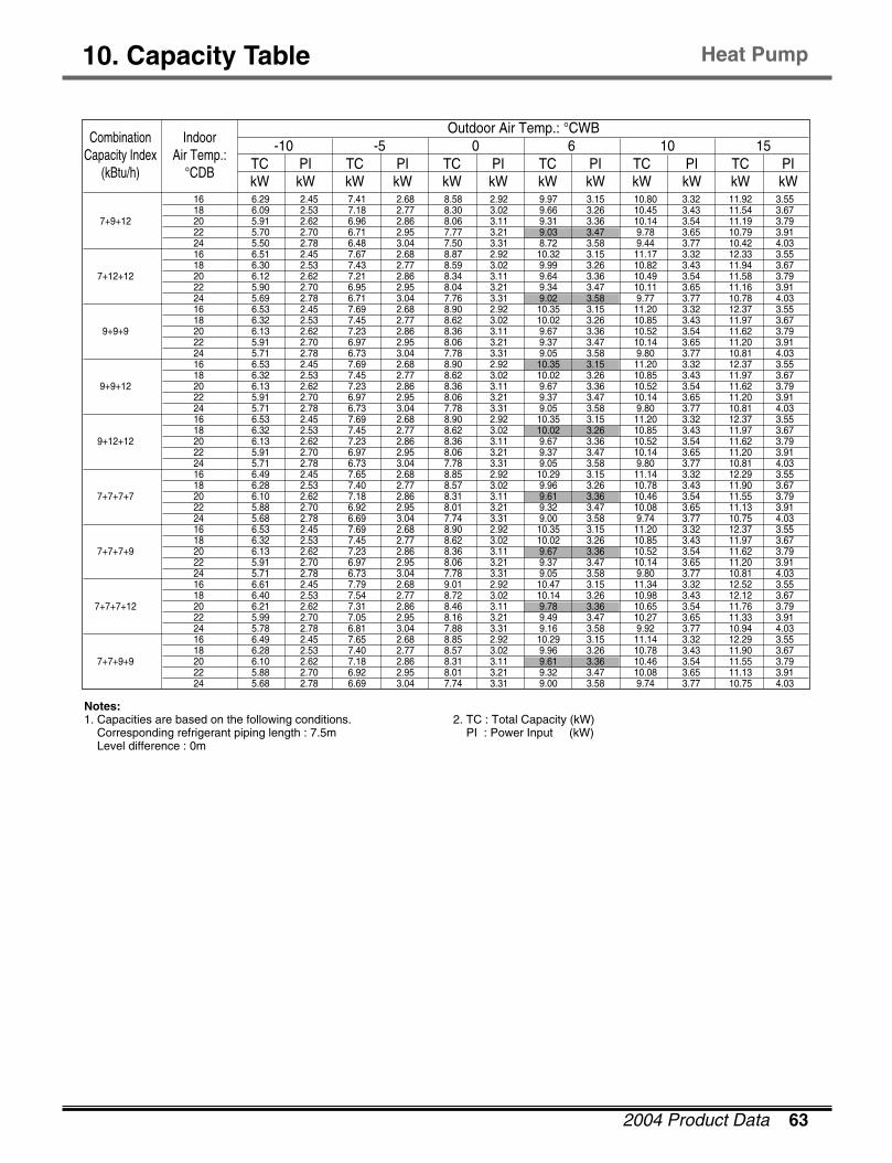
2004 Product Data 63
10. Capacity Table Heat Pump
TC PI TC PI TC PI TC PI TC PI TC PIkW kW kW kW kW kW kW kW kW kW kW kW
CombinationCapacity Index
(kBtu/h)
Indoor Air Temp.:
°CDB
-10 -5 0 6 10 15Outdoor Air Temp.: °CWB
16 6.29 2.45 7.41 2.68 8.58 2.92 9.97 3.15 10.80 3.32 11.92 3.55 18 6.09 2.53 7.18 2.77 8.30 3.02 9.66 3.26 10.45 3.43 11.54 3.67
7+9+12 20 5.91 2.62 6.96 2.86 8.06 3.11 9.31 3.36 10.14 3.54 11.19 3.79 22 5.70 2.70 6.71 2.95 7.77 3.21 9.03 3.47 9.78 3.65 10.79 3.91 24 5.50 2.78 6.48 3.04 7.50 3.31 8.72 3.58 9.44 3.77 10.42 4.03 16 6.51 2.45 7.67 2.68 8.87 2.92 10.32 3.15 11.17 3.32 12.33 3.55 18 6.30 2.53 7.43 2.77 8.59 3.02 9.99 3.26 10.82 3.43 11.94 3.67
7+12+12 20 6.12 2.62 7.21 2.86 8.34 3.11 9.64 3.36 10.49 3.54 11.58 3.79 22 5.90 2.70 6.95 2.95 8.04 3.21 9.34 3.47 10.11 3.65 11.16 3.91 24 5.69 2.78 6.71 3.04 7.76 3.31 9.02 3.58 9.77 3.77 10.78 4.03 16 6.53 2.45 7.69 2.68 8.90 2.92 10.35 3.15 11.20 3.32 12.37 3.55 18 6.32 2.53 7.45 2.77 8.62 3.02 10.02 3.26 10.85 3.43 11.97 3.67
9+9+9 20 6.13 2.62 7.23 2.86 8.36 3.11 9.67 3.36 10.52 3.54 11.62 3.79 22 5.91 2.70 6.97 2.95 8.06 3.21 9.37 3.47 10.14 3.65 11.20 3.91 24 5.71 2.78 6.73 3.04 7.78 3.31 9.05 3.58 9.80 3.77 10.81 4.03 16 6.53 2.45 7.69 2.68 8.90 2.92 10.35 3.15 11.20 3.32 12.37 3.55 18 6.32 2.53 7.45 2.77 8.62 3.02 10.02 3.26 10.85 3.43 11.97 3.67
9+9+12 20 6.13 2.62 7.23 2.86 8.36 3.11 9.67 3.36 10.52 3.54 11.62 3.79 22 5.91 2.70 6.97 2.95 8.06 3.21 9.37 3.47 10.14 3.65 11.20 3.91 24 5.71 2.78 6.73 3.04 7.78 3.31 9.05 3.58 9.80 3.77 10.81 4.03 16 6.53 2.45 7.69 2.68 8.90 2.92 10.35 3.15 11.20 3.32 12.37 3.55 18 6.32 2.53 7.45 2.77 8.62 3.02 10.02 3.26 10.85 3.43 11.97 3.67
9+12+12 20 6.13 2.62 7.23 2.86 8.36 3.11 9.67 3.36 10.52 3.54 11.62 3.79 22 5.91 2.70 6.97 2.95 8.06 3.21 9.37 3.47 10.14 3.65 11.20 3.91 24 5.71 2.78 6.73 3.04 7.78 3.31 9.05 3.58 9.80 3.77 10.81 4.03 16 6.49 2.45 7.65 2.68 8.85 2.92 10.29 3.15 11.14 3.32 12.29 3.55 18 6.28 2.53 7.40 2.77 8.57 3.02 9.96 3.26 10.78 3.43 11.90 3.67
7+7+7+7 20 6.10 2.62 7.18 2.86 8.31 3.11 9.61 3.36 10.46 3.54 11.55 3.79 22 5.88 2.70 6.92 2.95 8.01 3.21 9.32 3.47 10.08 3.65 11.13 3.91 24 5.68 2.78 6.69 3.04 7.74 3.31 9.00 3.58 9.74 3.77 10.75 4.03 16 6.53 2.45 7.69 2.68 8.90 2.92 10.35 3.15 11.20 3.32 12.37 3.55 18 6.32 2.53 7.45 2.77 8.62 3.02 10.02 3.26 10.85 3.43 11.97 3.67
7+7+7+9 20 6.13 2.62 7.23 2.86 8.36 3.11 9.67 3.36 10.52 3.54 11.62 3.79 22 5.91 2.70 6.97 2.95 8.06 3.21 9.37 3.47 10.14 3.65 11.20 3.91 24 5.71 2.78 6.73 3.04 7.78 3.31 9.05 3.58 9.80 3.77 10.81 4.03 16 6.61 2.45 7.79 2.68 9.01 2.92 10.47 3.15 11.34 3.32 12.52 3.55 18 6.40 2.53 7.54 2.77 8.72 3.02 10.14 3.26 10.98 3.43 12.12 3.67
7+7+7+12 20 6.21 2.62 7.31 2.86 8.46 3.11 9.78 3.36 10.65 3.54 11.76 3.79 22 5.99 2.70 7.05 2.95 8.16 3.21 9.49 3.47 10.27 3.65 11.33 3.91 24 5.78 2.78 6.81 3.04 7.88 3.31 9.16 3.58 9.92 3.77 10.94 4.03 16 6.49 2.45 7.65 2.68 8.85 2.92 10.29 3.15 11.14 3.32 12.29 3.55 18 6.28 2.53 7.40 2.77 8.57 3.02 9.96 3.26 10.78 3.43 11.90 3.67
7+7+9+9 20 6.10 2.62 7.18 2.86 8.31 3.11 9.61 3.36 10.46 3.54 11.55 3.79 22 5.88 2.70 6.92 2.95 8.01 3.21 9.32 3.47 10.08 3.65 11.13 3.91 24 5.68 2.78 6.69 3.04 7.74 3.31 9.00 3.58 9.74 3.77 10.75 4.03
Notes:1. Capacities are based on the following conditions.
Corresponding refrigerant piping length : 7.5mLevel difference : 0m
2. TC : Total Capacity (kW)PI : Power Input (kW)
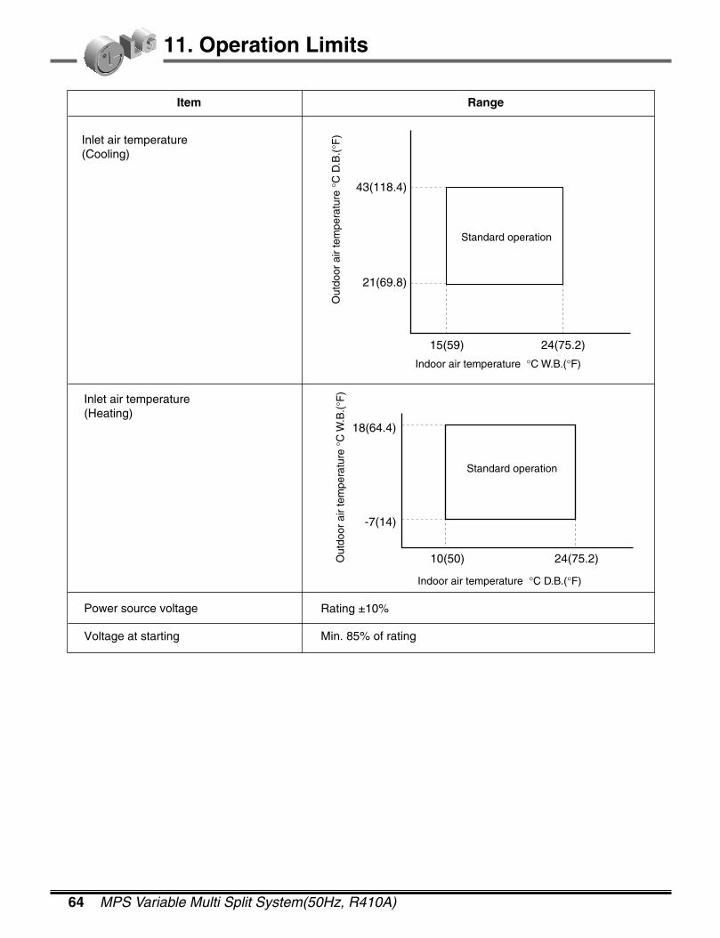
64 MPS Variable Multi Split System(50Hz, R410A)
11. Operation Limits
Item Range
Inlet air temperature(Cooling)
Inlet air temperature(Heating)
Power source voltage
Voltage at starting
Rating ±10%
Min. 85% of rating
43(118.4)
21(69.8)
15(59) 24(75.2)
Indoor air temperature °C W.B.(°F)
Out
door
air
tem
pera
ture
°C
D.B
.(°F
)
Standard operation
Indoor air temperature °C D.B.(°F)
Standard operation
Out
door
air
tem
pera
ture
°C
W.B
.(°F
)
18(64.4)
10(50) 24(75.2)
-7(14)

2004 Product Data 65
12. Air Velocity and Temperature Distributions(Reference Data)
7k Btu/h Model
12.2 ART COOL Type12k Btu/h Model
Air velocity [m/s]2.7m
2m
1m
0m0m1m2m3m4m5m
1.5
1.0
0.5
Temperature [˚C]2.7m
2m
1m
0m0m1m2m3m4m5m
18
20
2224
Air velocity [m/s]2.7m
2m
1m
0m0m1m2m3m4m5m
1.5
1.0
0.5
Temperature [˚C]2.7m
2m
1m
0m0m1m2m3m4m5m
33
30
27
2421
CoolingDischarge angle:45°
HeatingDischarge angle:50°
Air velocity [m/s]2.7m
2m
1m
0m0m1m2m3m4m5m
Temperature [ßC]2.7m
2m
1m
0m0m1m2m3m4m5m
2.0
1.5
1.00.5
18
20
2224
Air velocity [m/s]2.7m
2m
1m
0m0m1m2m3m4m5m
Temperature [ßC]2.7m
2m
1m
0m0m1m2m3m4m5m
2.0
1.5
1.00.5
30
27
2421
CoolingDischarge angle:45°
HeatingDischarge angle:50°
12.1 Wall Mounted Type
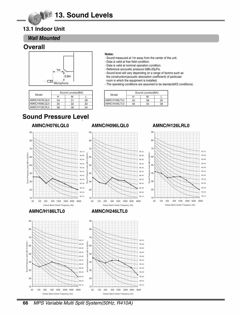
66 MPS Variable Multi Split System(50Hz, R410A)
13. Sound Levels
Overall
Sound Pressure LevelAMNC/H076LQL0 AMNC/H096LQL0 AMNC/H126LRL0
AMNC/H186LTL0 AMNC/H246LTL0
Model
AMNC/H076LQL0AMNC/H096LQL0AMNC/H126LRL0
Sound Levels(dBA)
H M L343538
313236
283034
Model
AMNC/H186LTL0AMNC/H246LTL0
Sound Levels(dBA)
H M L4246
3840
3538
0.8m
1m
Microphone
Notes:- Sound measured at 1m away from the center of the unit.- Data is valid at free field condition.- Data is valid at nominal operation condition.- Reference accoustic pressure 0dB=20µPa.- Sound level will vary depending on a range of factors such as the construction(acoustic absorption coefficient) of particular room in which the equipment is installed.- The operating conditions are assumed to be standard(KS conditions).
10
20
30
40
50
60
70
80
90
NC-15
NC-70
NC-65
NC-60
NC-55
NC-50
NC-45
NC-40
NC-35
NC-30
NC-25
NC-20
Sou
nd P
ress
ure
Leve
l (dB
re
20µP
a )
Octave Band Center Frequency (Hz)
63 125 250 500 1000 2000 4000 800010
20
30
40
50
60
70
80
90
NC-15
NC-70
NC-65
NC-60
NC-55
NC-50
NC-45
NC-40
NC-35
NC-30
NC-25
NC-20
Sou
nd P
ress
ure
Leve
l (dB
re
20µP
a )
Octave Band Center Frequency (Hz)
63 125 250 500 1000 2000 4000 8000
10
20
30
40
50
60
70
80
90
NC-15
NC-70
NC-65
NC-60
NC-55
NC-50
NC-45
NC-40
NC-35
NC-30
NC-25
NC-20
Sou
nd P
ress
ure
Leve
l (dB
re
20µP
a )
Octave Band Center Frequency (Hz)
63 125 250 500 1000 2000 4000 800010
20
30
40
50
60
70
80
90
NC-15
NC-70
NC-65
NC-60
NC-55
NC-50
NC-45
NC-40
NC-35
NC-30
NC-25
NC-20
Sou
nd P
ress
ure
Leve
l (dB
re
20µP
a )
Octave Band Center Frequency (Hz)
63 125 250 500 1000 2000 4000 800010
20
30
40
50
60
70
80
90
NC-15
NC-70
NC-65
NC-60
NC-55
NC-50
NC-45
NC-40
NC-35
NC-30
NC-25
NC-20
Sou
nd P
ress
ure
Leve
l (dB
re
20µP
a )
Octave Band Center Frequency (Hz)
63 125 250 500 1000 2000 4000 8000
13.1 Indoor Unit
Wall Mounted
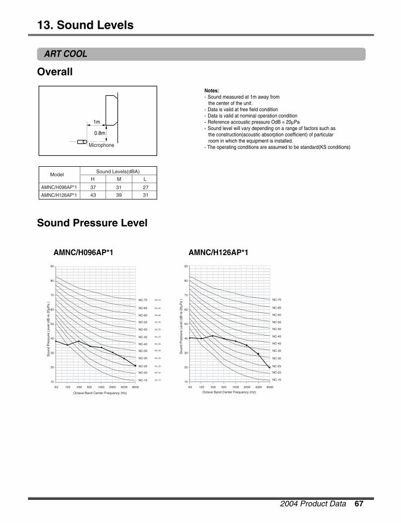
2004 Product Data 67
ART COOL
13. Sound Levels
Overall
Sound Pressure Level
AMNC/H096AP*1 AMNC/H126AP*1
Notes:- Sound measured at 1m away from the center of the unit.- Data is valid at free field condition- Data is valid at nominal operation condition- Reference accoustic pressure OdB = 20µPa - Sound level will vary depending on a range of factors such as the construction(acoustic absorption coefficient) of particular room in which the equipment is installed.- The operating conditions are assumed to be standard(KS conditions)
Model
AMNC/H096AP*1
AMNC/H126AP*1
Sound Levels(dBA)
H M L
37
43
31
39
27
31
10
20
30
40
50
60
70
80
90
63 125 250 500 1000 2000 4000 8000
Octave Band Center Frequency (Hz)
NC-15
NC-70
NC-65
NC-60
NC-55
NC-50
NC-45
NC-40
NC-35
NC-30
NC-25
NC-20
10
20
30
40
50
60
70
80
90
63 125 250 500 1000 2000 4000 8000
Octave Band Center Frequency (Hz)
NC-15
NC-70
NC-65
NC-60
NC-55
NC-50
NC-45
NC-40
NC-35
NC-30
NC-25
NC-20
Sou
nd P
ress
ure
Leve
l (dB
re
20µP
a )
Sou
nd P
ress
ure
Leve
l (dB
re
20µP
a )
NC-15
NC-70
NC-65
NC-60
NC-55
NC-50
NC-45
NC-40
NC-35
NC-30
NC-25
NC-20
0.8m
1m
Microphone
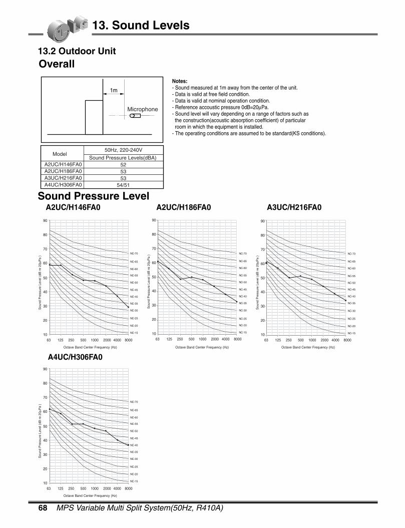
68 MPS Variable Multi Split System(50Hz, R410A)
13. Sound Levels
13.2 Outdoor UnitOverall
Sound Pressure LevelA2UC/H146FA0 A2UC/H186FA0 A3UC/H216FA0
A4UC/H306FA0
Model
A2UC/H146FA0A2UC/H186FA0A3UC/H216FA0A4UC/H306FA0
50Hz, 220-240V
Sound Pressure Levels(dBA)525353
54/51
1m
Notes:- Sound measured at 1m away from the center of the unit.- Data is valid at free field condition.- Data is valid at nominal operation condition.- Reference accoustic pressure 0dB=20µPa.- Sound level will vary depending on a range of factors such as the construction(acoustic absorption coefficient) of particular room in which the equipment is installed.- The operating conditions are assumed to be standard(KS conditions).
10
20
30
40
50
60
70
80
90
NC-15
NC-70
NC-65
NC-60
NC-55
NC-50
NC-45
NC-40
NC-35
NC-30
NC-25
NC-20
Sou
nd P
ress
ure
Leve
l (dB
re
20µP
a )
63 125 250 500 1000 2000 4000 800010
20
30
40
50
60
70
80
90
NC-15
NC-70
NC-65
NC-60
NC-55
NC-50
NC-45
NC-40
NC-35
NC-30
NC-25
NC-20
Sou
nd P
ress
ure
Leve
l (dB
re
20µP
a )
63 125 250 500 1000 2000 4000 800010
20
30
40
50
60
70
80
90
NC-15
NC-70
NC-65
NC-60
NC-55
NC-50
NC-45
NC-40
NC-35
NC-30
NC-25
NC-20
Sou
nd P
ress
ure
Leve
l (dB
re
20µP
a )
63 125 250 500 1000 2000 4000 8000
Microphone
Octave Band Center Frequency (Hz) Octave Band Center Frequency (Hz) Octave Band Center Frequency (Hz)
10
20
30
40
50
60
70
80
90
NC-15
NC-70
NC-65
NC-60
NC-55
NC-50
NC-45
NC-40
NC-35
NC-30
NC-25
NC-20
Sou
nd P
ress
ure
Leve
l (dB
re
20µP
a )
63 125 250 500 1000 2000 4000 8000
Octave Band Center Frequency (Hz)
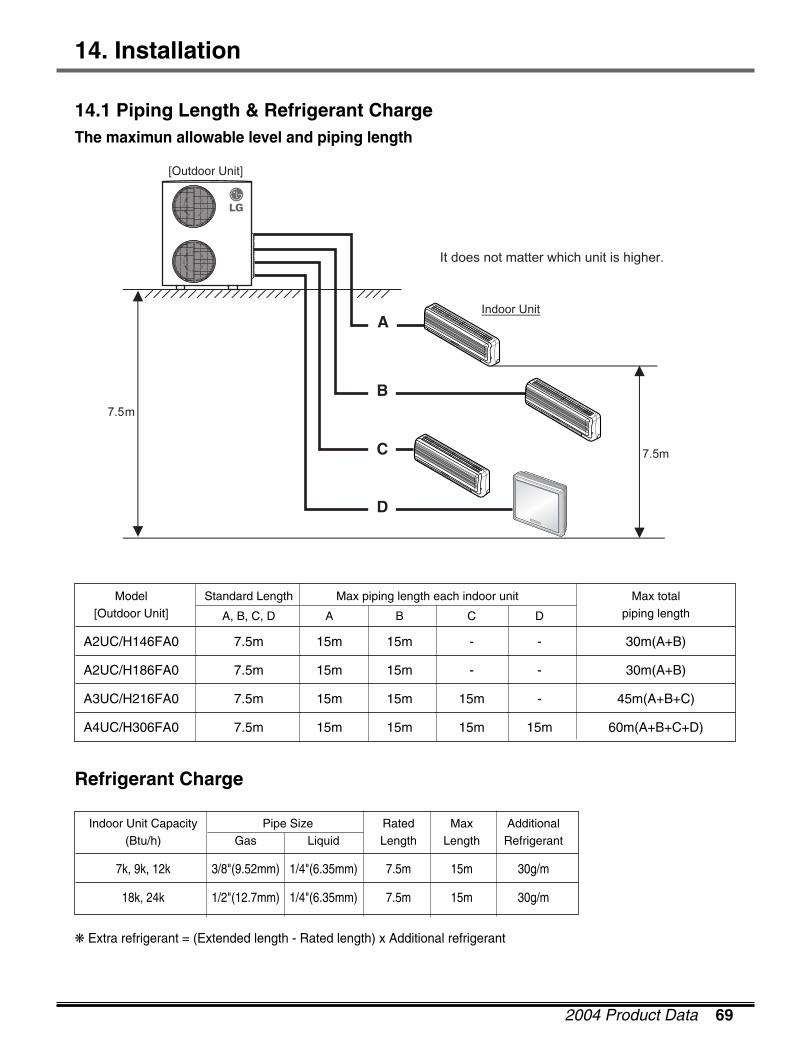
2004 Product Data 69
14. Installation
14.1 Piping Length & Refrigerant ChargeThe maximun allowable level and piping length
7.5m
It does not matter which unit is higher.
7.5m
Indoor UnitA
B
C
D
[Outdoor Unit]
Indoor Unit Capacity Pipe Size Rated Max Additional(Btu/h) Gas Liquid Length Length Refrigerant
7k, 9k, 12k 3/8"(9.52mm) 1/4"(6.35mm) 7.5m 15m 30g/m
18k, 24k 1/2"(12.7mm) 1/4"(6.35mm) 7.5m 15m 30g/m
Refrigerant Charge
❋ Extra refrigerant = (Extended length - Rated length) x Additional refrigerant
Model Standard Length Max piping length each indoor unit Max total[Outdoor Unit] A, B, C, D A B C D piping length
A2UC/H146FA0 7.5m 15m 15m - - 30m(A+B)
A2UC/H186FA0 7.5m 15m 15m - - 30m(A+B)
A3UC/H216FA0 7.5m 15m 15m 15m - 45m(A+B+C)
A4UC/H306FA0 7.5m 15m 15m 15m 15m 60m(A+B+C+D)
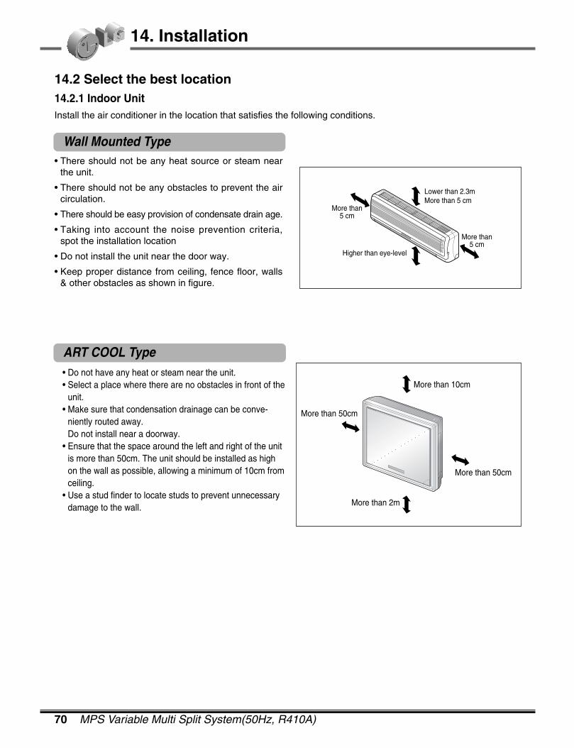
70 MPS Variable Multi Split System(50Hz, R410A)
14. Installation
• There should not be any heat source or steam nearthe unit.
• There should not be any obstacles to prevent the aircirculation.
• There should be easy provision of condensate drain age.
• Taking into account the noise prevention criteria,spot the installation location
• Do not install the unit near the door way.
• Keep proper distance from ceiling, fence floor, walls& other obstacles as shown in figure.
Lower than 2.3mMore than 5 cm
Higher than eye-level
More than5 cm
More than5 cm
14.2 Select the best location14.2.1 Indoor UnitInstall the air conditioner in the location that satisfies the following conditions.
Wall Mounted Type
ART COOL Type• Do not have any heat or steam near the unit.• Select a place where there are no obstacles in front of the
unit.• Make sure that condensation drainage can be conve-
niently routed away.Do not install near a doorway.
• Ensure that the space around the left and right of the unitis more than 50cm. The unit should be installed as highon the wall as possible, allowing a minimum of 10cm fromceiling.
• Use a stud finder to locate studs to prevent unnecessarydamage to the wall.
More than 10cm
More than 50cm
More than 2m
More than 50cm

2004 Product Data 71
14. Installation
14.2.2 Outdoor Unit• If an awning or canopy is built over the unit to prevent direct sunlight or rain exposure, make sure that heat
radiation from the condenser is not restricted.
• Ensure that the space around the back is more than 20~30cm and sides is more than 20~30cm. The front ofthe unit should have more than 70cm of space.
• Do not place animals and plants in the path of the warm air.
• Take the air conditioner weight into account and select a place where noise and vibration are minimum.
• Select a place so that the warm air and noise from the air conditioner do not disturb neighbors.
• Rooftop Installations : If the outdoor unit is installed on a roof structure, be sure to level the unit. Ensure theroof structure and anchoring method are adequate for the unit location. Consult local codes regarding rooftopmounting.
14.3 Settlement of outdoor unit
• Anchor the outdoor unit with a bolt and nut(ø10mm) tight-ly and secure it horizontally on a concrete or rigid mount.
• When installing on the wall, roof or rooftop, anchor themounting base securely with a nail or wire assuming theinfluence of wind and earthquake.
• In the case when the vibration of the unit is conveyed tothe hose, secure the unit with an anti-vibration rubber.
More than 30cmMore than 30cm
More than 70cm
More than 20 cm More than 20 cm
More than 70 cm
Bolt Tubing connection

72 MPS Variable Multi Split System(50Hz, R410A)
14. Installation
14.4 Connecting Pipings and the cable to Outdoor unit14.4.1 Connecting the pipings to the Outdoor unit
1. While installing pipes, you must use the connector. 2. Align the center of the pipings and tighten the flarenut by hand
3. Finally, tighten the flare nut with torque wrench untilthe wrench clicks.� When tightening the flare nut with torque wrench,
ensure the direction for tightening follows the arrow onthe wrench.
*Connecting pipe size
Indoor Units Gas LiquidA B A B
18k, 24k Ø9.52�Ø12.7 Not necessary
Indoor Units Gas side Liquid side7k Ø9.52(3/8) Ø6.35(1/4)9k Ø9.52(3/8) Ø6.35(1/4)12k Ø9.52(3/8) Ø6.35(1/4)18k Ø12.7(1/2) Ø6.35(1/4)24k Ø12.7(1/2) Ø6.35(1/4)
A BConnector
Gas side piping
Liquid side piping
Torque wrench
B-UNIT
A-UNITOutdoor unit
Connect the cable to the indoor unit by connecting the wires to the terminals on the control board indi-vidually according to the outdoor unit connection. (Ensure that the color of the wires of the outdoor unit andthe terminal No. are the same as those of the indoor unit.)The earth wire should be longer than the common wires.The circuit diagram is not subject to change without notice.When installing, refer to the circuit diagram of indoor & outdoor unit. Indoor connection circuit is behindthe front panel & outdoor connection circuit is inside the control cover.
CAUTION: • The circuit diagram is not subject to change without notice. • Be sure to connect wires according to the wiring diagram.• Connect the wires firmly, so that not to be pulled out easily.• Connect the wires according to color codes as referred in the wiring diagram.
14.4.2 Connect the cable
Connecting the cable to the Indoor unit.
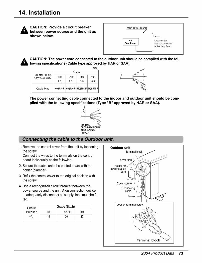
2004 Product Data 73
14. Installation
Connecting the cable to the Outdoor unit.
CAUTION: Provide a circuit breakerbetween power source and the unit asshown below.
CAUTION: The power cord connected to the outdoor unit should be complied with the fol-lowing specifications (Cable type approved by HAR or SAA).
The power connecting cable connected to the indoor and outdoor unit should be com-plied with the following specifications (Type "B" approved by HAR or SAA).
Air Conditioner
Main power source
Circuit BreakerUse a circuit breakeror time delay fuse.
GN/YL
20mm
18k 24k 30k 40k
2.5 2.5 3.5 5.5
Cable Type H05RN-F H05RN-F H05RN-F H05RN-F
NORMAL CROSSSECTIONAL AREA
Grade
(mm2)
NORMALCROSS-SECTIONALAREA 0.75mm2
H05VV-F
ø7.5
mm
GN/YL
20mm
1. Remove the control cover from the unit by looseningthe screw.Connect the wires to the terminals on the controlboard individually as the following.
2. Secure the cable onto the control board with theholder (clamper).
3. Refix the control cover to the original position withthe screw.
4. Use a recongnized circuit breaker between thepower source and the unit. A disconnection deviceto adequately disconnect all supply lines must be fit-ted.
CircuitBreaker
(A)
Grade (Btu/h)
14k 18k/21k 30k15 20 30
Power cord
Connectingcable
Cover control
Terminal blockOutdoor unit
Over 5mm
Holder forpower supply
cord
Loosen terminal screw
Terminal block
74 MPS Variable Multi Split System(50Hz, R410A)
14. Installation
CAUTION
After the confirmation of the above conditions, prepare the wiring as follows.1. Never fail to have an individual power circuit specifically for the air conditioner. For wiring,
methed take guidance from the circuit diagram posted on the inside of control cover.2. Firmly tighten the terminal screws to prevent them loosening. After tightening, pull the wires
lightly to confirm that they do not move. (If they are loose the unit will not operate normally or itcan cause burn-out of the wires.)
3. Check specification of power source.4. Confirm that electrical capacity is sufficient.5. See to that the starting voltage is maintained at more than 90 percent of the rated voltage marked
on the name plate.6. Confirm that the cable thickness is as specified in the power source specification.
(Particularly note the relation between cable length and thickness.7. An earth leakage circuit breaker should be equiped in a wet or moist area.8. The following would be caused by voltage drop.
• Vibration of a magnetic switch, which will damage the contact point, fuse breaking, disturbanceof the normal function of the overload.
9. The means for disconnection from a power supply shall be incorporated in the fixed wiring andhave an air gap contact separation of at least 3mm in each active(phase) conductors.

2004 Product Data 75
14. Installation
14.5 Drain Pipe Work❑ Drain pipe gradient and support
1) - The drain pipe must be fitted at a gradient of at least 1/100.- The drain pipe should be as short as possible and free from airlocks.
2) Suspension bolts should be used to support long stretches of drain pipe in order to ensure that a gradientof 1/100 is maintained.(PVC pipe should not be bent)
Spacing of supports for horizontal piping
3) The length of pipe laid horizontally should be kept a minimum.
❑ Drain trap
Fit any indoor unit whose drain pipe connection is subjected to negative pressure, with a drain trap.
1) Rig the drain trap as shown in the drawing below
2) Provide one trap per unit. A single trap for converging units will prove ineffective.
3) Rig the trap to allow for future changing.
Class Nominal diameter Spacing
Rigid PVC pipe 25~40mm 1.0m or less
Indoor unit
Gradient of at least 1 / 100(1cm/ 1m)
Indoor unit
H: 50mm or moreH
H
Indoor unit
Plug
Indoor unit
Plug

76 MPS Variable Multi Split System(50Hz, R410A)
15. Function of Remote Controller
ON OFF
CANCEL
AUTO CLEANSET
1
3
5
4
9
10
17
18
16
7
2
8
13
14
15
11
6
12
Cooling Operation
Auto Operation
Healthy Dehumidification Operation
Flip-up door(opened)
Heating Operation
Signal transmitter
• Cooling Model( ), Heat Pump Model( )
Operation Mode
START/STOP BUTTONOperation starts when this button is pressed andstops when the button is pressed again.OPERATION MODE SELECTION BUTTONUsed to select the operation mode.ROOM TEMPERATURE SETTING BUTTONSUsed to select the room temperature.INDOOR FAN SPEED SELECTORUsed to select fan speed in four stepslow, medium, high and CHAOS.JET COOLUsed to start or stop the speed cooling. (Speed cooling operates super high fan speed in cooling mode.)CHAOS SWING BUTTONUsed to stop or start louver movement and setthe desired up/down airflow direction.ON/OFF TIMER BUTTONSUsed to set the time of starting and stoppingoperation.TIME SETTING BUTTONSUsed to adjust the time.TIMER SET/CANCEL BUTTONUsed to set the timer when the desired time isobtained and to cancel the Timer operation.SLEEP MODE AUTO BUTTONUsed to set Sleep Mode Auto operation. AIR CIRCULATION BUTTONUsed to circulate the room air without cooling orheating.ROOM TEMPERATURE CHECKING BUTTONUsed to check the room temperature.PLASMA(OPTIONAL)Used to start or stop the plasma-purification func-tion.HORIZONTAL AIRFLOW DIRECTIONCONTROL BUTTON (NOT ON ALL MODELS)Used to set the desired horizontal airflow direc-tion.RESET BUTTONUsed prior to resetting time or after replacing bat-teries.2nd F ButtonUsed prior to using modes printed in blue at thebottom of buttons.AUTO CLEANUsed to set Auto Clean mode.LED LUMINOSITYUsed to adjust LED luminosity.
1
2
3
4
5
6
7
8
9
10
11
12
13
14
15
16
17
18
15.1 Wireless LCD Remote Controller

P/No.: 3828A20428F
20 Yoido-dong, Youngdungpo-gu, Yoido P.O.Box 355Seoul 150-721, Korea
Phone: 3777-7969 Fax: 3777-5137/8http://www.lge.comhttp://biz.lgservice.com
For continual product development, LG reserves the right to change specifications without notice©LG Electronics INC. Printed in Korea. December/2003


![Revenue Town Hall Flyers · 7*356"-508/)"--8 L $ êé ^ FA ^ B? D68;EF6DFAB2DF;4;B2F6 OWc\ZhªMZOM]hc^f]VMZZ](https://img.dokumen.tips/doc/110x75/5f8e08d5bac90a7af17a63f4/revenue-town-hall-flyers-7356-508-8-l-fa-b-d68ef6dfab2df4b2f6.jpg)