Embed Size (px)
Citation preview

1
130
Mount Kelly Project Environmental Management Plan Prepared for: CopperCo Limited January 2006
13-137 File B Documents Page 1 of 174
Released

EM Plan i January 2006
Document History and Status Issue Rev. Issued To Qty Date Reviewed Approved
1 Draft CopperCo Limited 1 10/01/06 F.Tromans F.Tromans 1 Draft AARC 1 12/01/06 C. Bentsen F.Tromans 2 Final AARC 1 16/01/05 C. Bentsen 2 Final CopperCo Limited 1 23/01/06 P. Macey F.Tromans 2 Final QEPA 1 23/01/06 P. Macey F.Tromans 3 Final CopperCo Limited 1 25/05/06 F.Tromans F.Tromans 3 Final QEPA 1 29/05/06 F.Tromans F.Tromans
Last Saved: 29 May, 2006 File Name: C:\Fiona Files\Clients\Copper Co\EM Plan - Mount Kelly\Revised
Copy May 2006\CCEM Planfinal290506ft.Doc Author: Fiona Tromans Project Manager: Fiona Tromans Name of Client : CopperCo Limited Name of Project: Mount Kelly Project Title of Document: Environmental Management Plan Document Version: Final
This controlled document is the property of AustralAsian Resource Consultants Pty Ltd and all rights are reserved in respect of it. This document may not be reproduced or disclosed in any manner whatsoever, in
whole or in part, without the prior written consent of AustralAsian Resource Consultants Pty Ltd. AustralAsian Resource Consultants Pty Ltd expressly disclaims any responsibility for or liability arising from the use of this
document by any third party.
13-137 File B Documents Page 2 of 174

EM Plan i January 2006
1.0 INTRODUCTION AND OVERVIEW ................................................................ 1
2.0 DESCRIPTION OF THE MINING TENURE .................................................... 3 2.1 PROJECT NAME AND LOCATION .....................................................................................3 2.2 MINING LEASES COVERED BY THE EM PLAN................................................................4 2.3 RELEVANT STAKEHOLDERS.............................................................................................6 2.4 REAL PROPERTY DESCRIPTION AND CURRENT DISTURBANCE TYPES...................8 2.5 ENVIRONMENTALLY SENSITIVE LOCATIONS.................................................................9 2.6 WILD RIVERS LEGISLATION............................................................................................11
3.0 DESCRIPTION OF THE EXISTING ENVIRONMENT................................... 12 3.1 REGIONAL CLIMATE.........................................................................................................12 3.2 GEOLOGY...........................................................................................................................12 3.3 SOIL AND LAND USE SUITABILITY.................................................................................13 3.4 FLORA AND FAUNA..........................................................................................................16
3.4.1 Field Survey Methods......................................................................................................17 3.4.2 Field Results....................................................................................................................17
3.5 STREAM SEDIMENT AND MORPHOLOGY STUDY ........................................................21 3.6 SURFACE WATER AND DRAINAGE ................................................................................24
3.6.1 Plant Site .........................................................................................................................24 3.6.2 Mount Clarke Mining Area...............................................................................................24 3.6.3 Mount Kelly/Flying Horse Mining Area ............................................................................25 3.6.4 Sediment Dams...............................................................................................................25 3.6.5 Surface Water Quality .....................................................................................................26
3.7 GROUNDWATER................................................................................................................26 3.7.1 Groundwater Quality .......................................................................................................27 3.7.2 Groundwater Dewatering ................................................................................................27 3.7.3 Heap Leach Area ............................................................................................................28
3.8 WASTE ROCK CHARACTERISATION..............................................................................29 3.9 CULTURAL HERITAGE......................................................................................................30 3.10 ENVIRONMENTAL RISK ASSESSMENT..........................................................................30
3.10.1 Land Clearing ..................................................................................................................32 3.10.2 Heap Leach Pads............................................................................................................32 3.10.3 Transport .........................................................................................................................33
4.0 DESCRIPTION OF MINING ACTIVITIES ..................................................... 34 4.1 ENVIRONMENTALLY RELEVANT ACTIVITIES ...............................................................34 4.2 EXPLORATION...................................................................................................................35 4.3 VEGETATION REMOVAL AND TOPSOIL STRIPPING ....................................................35 4.4 MINING OF THE DEPOSITS ..............................................................................................37 4.5 WASTE ROCK DUMPS ......................................................................................................40 4.6 PROCESSING ACTIVITIES................................................................................................40
4.6.1 Ore Stacking and Heap Leach Pad Design ....................................................................40 4.6.2 Copper Leaching Process ...............................................................................................41 4.6.3 Solvent Extraction (SX) and Electro-winning (EW) Process ...........................................41 4.6.4 Process Water and Stormwater Ponds ...........................................................................41
TABLE OF CONTENTS
13-137 File B Documents Page 3 of 174

EM Plan ii January 2006
4.7 RAW WATER POND...........................................................................................................44 4.8 WATER REQUIREMENTS..................................................................................................44 4.9 POWER SUPPLY................................................................................................................45 4.10 CONCRETE BATCHING.....................................................................................................45 4.11 ACCOMMODATION CAMP................................................................................................45 4.12 SEWAGE TREATMENT......................................................................................................46 4.13 GENERAL INFRASTRUCTURE.........................................................................................49 4.14 TRANSPORT ......................................................................................................................50
5.0 REHABILITATION ........................................................................................ 51 5.1 EXPLORATION...................................................................................................................51 5.2 HEAP LEACH PADS ..........................................................................................................51 5.3 WASTE ROCK DUMPS ......................................................................................................51 5.4 FINAL VOIDS ......................................................................................................................52 5.5 PLANT AND INFRASTRUCTURE......................................................................................52 5.6 ACCESS ROADS................................................................................................................52 5.7 REVEGETATION METHODS .............................................................................................52
6.0 ENVIRONMENTAL VALUES, IMPACTS, CONTROL STRATEGIES AND PROPOSED EA CONDITIONS ............................................................................... 53
6.1 GENERAL EA CONDITIONS..............................................................................................53 6.2 AIR.......................................................................................................................................55
6.2.1 Environmental Value .......................................................................................................55 6.2.2 Description of Environmental Value ................................................................................55 6.2.3 Assessment of Impacts on the Environmental Values....................................................55 6.2.4 Proposed Environmental Protection Objective................................................................55 6.2.5 Control Strategies............................................................................................................56 6.2.6 Proposed EA Conditions using Measurable Indicators and Standards ..........................56
6.3 WATER MANAGEMENT ....................................................................................................58 6.3.1 Environmental Value .......................................................................................................58 6.3.2 Description of Environmental Value ................................................................................58 6.3.3 Assessment of Impacts on the Environmental Values....................................................58 6.3.4 Proposed Environmental Protection Objective................................................................59 6.3.5 Control Strategies............................................................................................................59 6.3.6 Proposed EA Conditions using Measurable Indicators and Standards ..........................60
6.4 NOISE AND VIBRATION....................................................................................................73 6.4.1 Environmental Value .......................................................................................................73 6.4.2 Description of Environmental Values ..............................................................................73 6.4.3 Assessment of Impacts on the Environmental Values....................................................73 6.4.4 Proposed Environmental Protection Objective................................................................73 6.4.5 Control Strategies............................................................................................................73 6.4.6 Proposed EA Conditions using Measurable Indicators and Standards ..........................74
6.5 WASTE MANAGEMENT.....................................................................................................75 6.5.1 Environmental Value .......................................................................................................75 6.5.2 Description of Environmental Value ................................................................................75 6.5.3 Assessment of Impacts on the Environmental Values....................................................75 6.5.4 Proposed Environmental Protection Objective................................................................75 6.5.5 Control Strategies............................................................................................................76 6.5.6 Proposed EA Conditions using Measurable Indicators and Standards ..........................76
6.6 LAND MANAGEMENT........................................................................................................78 6.6.1 Environmental Value .......................................................................................................78
13-137 File B Documents Page 4 of 174

EM Plan iii January 2006
6.6.2 Description of Environmental Value ................................................................................78 6.6.3 Assessment of Impacts on the Environmental Values....................................................78 6.6.4 Proposed Environmental Protection Objectives..............................................................78 6.6.5 Control Strategies............................................................................................................79 6.6.6 Proposed EA Conditions using Measurable Indicators and Standards ..........................80
6.7 COMMUNITY.......................................................................................................................85 6.7.1 Environmental Value .......................................................................................................85 6.7.2 Description of Environmental Values ..............................................................................85 6.7.3 Assessment of Impacts on the Environmental Values....................................................85 6.7.4 Proposed Environmental Protection Objective................................................................85 6.7.5 Control Strategies............................................................................................................85 6.7.6 Proposed EA Conditions using Measurable Indicators and Standards ..........................85
6.8 CULTURAL HERITAGE......................................................................................................86 6.8.1 Environmental Value .......................................................................................................86 6.8.2 Description of Environmental Values ..............................................................................86 6.8.3 Proposed Environmental Protection Objective................................................................86 6.8.4 Control Strategies............................................................................................................86
6.9 NATURE CONSERVATION................................................................................................87 6.9.1 Identified Environmental Value........................................................................................87 6.9.2 Description of Environmental Value ................................................................................87 6.9.3 Assessment of Impacts on the Environmental Values....................................................87 6.9.4 Proposed Environmental Protection Objective................................................................87 6.9.5 Control Strategies............................................................................................................87
6.10 CONTINUOUS IMPROVEMENT.........................................................................................90 6.11 STAFF TRAINING...............................................................................................................90 6.12 ENVIRONMENTAL AUDITING...........................................................................................91 6.13 ENVIRONMENTAL MANAGEMENT PLAN MILESTONES...............................................92
7.0 BIBLIOGRAPHY........................................................................................... 94
Figure 1: Regional Location of the Mount Kelly Project ...................................................................3 Figure 2: Location of the Mount Kelly Tenements............................................................................5 Figure 3: Location of Nearest Residences to the Project .................................................................7 Figure 4: Environmentally Sensitive Areas Map.............................................................................10 Figure 5: Distribution of Soil Mapping Units on the Mount Kelly Extended MLA............................14 Figure 6: Distribution of Soil Mapping Units on the Mount Kelly West MLA...................................15 Figure 7: Stream Sediment Sampling Sites Mount Kelly................................................................23 Figure 8: Conceptual Process Plant Layout ...................................................................................38 Figure 9: Conceptual Mining and Infrastructure Layout .................................................................39 Figure 10: Organisational Chart .......................................................................................................45 Figure 11: Treatment Process for Sewage Treatment Plant for the Accommodation Camp ...........47 Figure 12: Surface Water and Stream Sediment Monitoring Locations ...........................................61 Figure 13: Location of Process Plant Leak Detection Bores ............................................................69
LIST OF FIGURES
13-137 File B Documents Page 5 of 174

EM Plan iv January 2006
Table 1: Current Mining Lease within the Mount Kelly Project........................................................4 Table 2: MLAs to be added to the Mount Kelly Project ...................................................................4 Table 3: Real Property Descriptions for Project Tenements ...........................................................8 Table 4: Pre-Mining Land Suitability for Soil Mapping Units .........................................................16 Table 5: Vegetation Communities Identified on the Project Sites .................................................18 Table 6: Environment Protection and Biodiversity Conservation Act 1999 listed Migratory Bird
Species Observed by AARC Ecologists During the Copper Co Fauna Survey (2005). .20 Table 7: Stream Sediment Quality Results – Mount Kelly Project ................................................22 Table 8: Waste Rock Classification Criteria ..................................................................................30 Table 9: Qualitative Risk Analysis Matrix – Level of Risk .............................................................31 Table 10: ERAs Associated with the Project ...................................................................................34 Table 11: Land Clearance Required on the Project ........................................................................35 Table 12: Schedule C - Receiving Water Monitoring Locations and Frequency.............................61 Table 13: Schedule C - Receiving Water Contaminant Trigger Levels...........................................62 Table 14: Schedule C - Receiving Water Contaminant Limits ........................................................63 Table 15: Schedule C - End of Pipe Monitoring Locations and Frequency) ...................................63 Table 16: Schedule C - End of Pipe Contaminant Release Limits..................................................64 Table 17: Schedule C - Water Storage Monitoring Locations of Hazardous Dams........................64 Table 18: Schedule C – Water Quality in Dams Containing Hazardous Waste and Sediment
Ponds ..............................................................................................................................65 Table 19: Schedule C - Storage Design for Dams Containing Hazardous Waste..........................65 Table 20: Schedule C - Receiving Stream Sediment Monitoring Locations and Frequency ..........66 Table 21: Schedule C - Receiving Stream Sediment Contaminant Trigger Levels ........................66 Table 22: Schedule C - Receiving Stream Sediment Contaminant Limits......................................67 Table 23: Schedule C - Sewage Effluent Quality Targets for Dust Suppression............................67 Table 24: Schedule C - Groundwater Monitoring Locations and Frequency ..................................68 Table 25: Schedule C - Groundwater Contaminant Trigger Levels ................................................70 Table 26: Schedule C - Groundwater Contaminant Limits..............................................................71 Table 27: Schedule C - Voids Monitoring Locations and Frequency ..............................................71 Table 28: Schedule C - Void Water Quality Limits ..........................................................................72 Table 29: Schedule F - Final Land Use and Rehabilitation Approval Schedule .............................80 Table 30: Schedule F - Landform Design........................................................................................81 Table 31: Schedule F — Size and Purpose of Dams Containing Hazardous Waste......................82 Table 32: Schedule F — Location of Dams Containing Hazardous Waste ....................................82 Table 33: Summary of Milestones...................................................................................................92
LIST OF TABLES
13-137 File B Documents Page 6 of 174

EM Plan v January 2006
Appendix A: Soils and Land Use Suitability Study A Appendix B: Flora and Fauna Assessment B
Appendix C: Stream Sediment and Morphology Survey C Appendix D: Waste Rock Characterisation Report D Appendix E: European Cultural Heritage Assessment Report E Appendix F: Water Quality Data from Greenstone Creek – DNRM Stations F Appendix G: Environmental Risk Assessment Report G
VOLUME 2 - LIST OF APPENDICES
VOLUME 3 - LIST OF APPENDICES
13-137 File B Documents Page 7 of 174

EM Plan vi January 2006
AARC AustralAsian Resource Consultants Pty Ltd
ARI Annual Recurrence Interval
DNRM Department of Natural Resources and Mines
DSA Design Storage Allowance
EA Environmental Authority
EMOS Environmental Management Overview Strategy
EMM Environmental Monitoring Manual
EM Plan Environmental Management Plan
EMS Environmental Management System
EPBC Act 1999 Environmental Protection & Biodiversity Conservation Act, 1999
EP Act 1994 Environmental Protection Act, 1994
ERA Environmentally Relevant Activity
EW Electro-winning
ha hectares
HDPE High Density Polyethylene
ILS Intermediate Leach Solution
ILUA Indigenous Land Use Agreement
km kilometres
kL kilolitre
MW Megawatt
LIG Low Intensity Grazing
LME London Metals Exchange
m metre
m3 cubic metres
LIST OF ABBREVIATIONS
13-137 File B Documents Page 8 of 174

EM Plan vii January 2006
Mtpa Million tonnes per annum
ML Mining Lease
MLA Mining Lease Application
NAF Non Acid Forming
NCWR 1994 Nature Conservation (Wildlife) Regulation, 1994
PAF Potentially Acid Forming
PLS Pregnant Leach Solution
QEPA Queensland Environmental Protection Agency
ROM Run of Mine
SX Solvent Extraction
t tonne
tpa tonnes per annum
13-137 File B Documents Page 9 of 174

EM Plan 1 January 2006
1.0 INTRODUCTION AND OVERVIEW
The Mount Kelly Project1 (PJM90084) is owned and operated by CopperCo Limited. The Project has a Level 2 project approval Environmental Authority (EA) No M2499, which covers eight granted Mining Leases (MLs). Operations to date on these leases by CopperCo Limited have included exploration drilling and feasibility studies. Small scale historical mining has been carried out on some of the MLs by previous owners. The focus of this Environmental Management Plan (EM Plan) is to bring the Project into full operation as a copper oxide mining and processing project.
The proposed Project will include the open cut mining of copper oxide ore to extract up to 1.9 Million tonnes per annum (Mtpa) from the Mount Clarke and Flying Horse/Mount Kelly, deposits, over a mine life of eight years. Processing of the ore will be by heap leach, solvent extraction (SX) and electrowinning (EW) to produce up to 19,000 tonnes per annum (tpa) of London Metals Exchange (LME) Grade A copper cathode.
Ore from the Lady Annie deposit located approximately 20 km to the north of Project leases will also be hauled for processing on the Project site. The Lady Annie deposit will be a separate application to the QEPA due to different tenure ownership, and will be combined into the Mount Kelly Project after grant of the Lady Annie ML (Milestone 1).
A Supporting Information Document (AARC 2005) was lodged with an EA Amendment Application for the Project in November 2005, to detail the proposed Project and potential environmental impacts. The Queensland Environmental Protection Agency (QEPA) subsequently made an Assessment Level and Environmental Impact Statement (EIS) Decision for the Project on the 8 December 2005. The Assessment Level Decision was that the Project would be a Non Code Compliant Level 1 application with a significant increase in environmental harm. The QEPA also decided that an EIS was not required for the Project.
This EM Plan provides for the next step in the QEPA assessment process and the basis for the issue of a new draft EA for the Project. This EM Plan has been prepared in accordance with the QEPA Guideline 8 – Preparing an EMOS for Non-standard Mining Projects and section 203 of the Environmental Protection Act 1994.
This EM Plan has been brought about by the following proposed amendments to the Project:
Adding three new Mining Lease Applications (MLA) to the Project including Mount Clarke (MLA90168), Mount Kelly Extended (MLA90170) and Mount Kelly West (MLA90169);
Development of open cut mining on the Project tenements for oxide copper ore;
Development of a copper heap leach and a SX - EW process plant for producing LME Grade copper cathode;
Development of mining infrastructure associated with the proposed activities including an accommodation camp, roads, power and water supply; and
Upgrading the current EA for the Project (M2599) from a Level 2 Mining Project approval to a Level 1 Mining Project approval.
1 The Mount Kelly Project will be referred to as the Project from hereafter.
13-137 File B Documents Page 10 of 174

EM Plan 2 January 2006
This EM Plan will provide a description of the following:
Mining tenure(s);
Mining activities;
Environmental values and potential impacts from the Project on those values; and
Proposed EA condition(s) using measurable indicators and standards.
For each environmental value identified an assessment of the beneficial and adverse impacts from the Project to that value will be described. Environmental objectives and control strategies will be proposed for the protection of each environmental value and proposed EA conditions containing measurable standards and Indicators developed. These proposed EA conditions will be used to draft the EA by the QEPA.
Once the QEPA has issued the Final EA for the Project a Plan of Operations and Financial Assurance will be submitted to the Administrating Authority (Milestone 2).
13-137 File B Documents Page 11 of 174
Released

EM Plan 3 January 2006
2.0 DESCRIPTION OF THE MINING TENURE
2.1 PROJECT NAME AND LOCATION
The Mount Kelly Project is located within the Mt Isa Shire, approximately 100km north-west of Mt Isa (Figure 1).
The Project is located in an isolated and sparsely populated area. The main land uses of the surrounding area include low intensity cattle grazing, mineral exploration and mining.
Figure 1: Regional Location of the Mount Kelly Project
13-137 File B Documents Page 12 of 174
EM Plan 4 January 2006
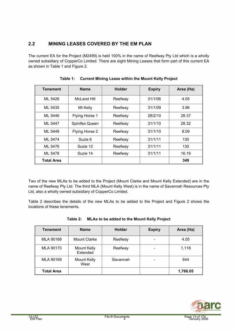
2.2 MINING LEASES COVERED BY THE EM PLAN
The current EA for the Project (M2499) is held 100% in the name of Reefway Pty Ltd which is a wholly owned subsidiary of CopperCo Limited. There are eight Mining Leases that form part of this current EA as shown in Table 1 and Figure 2.
Table 1: Current Mining Lease within the Mount Kelly Project
Tenement Name Holder Expiry Area (Ha)
ML 5426 McLeod Hill Reefway 31/1/06 4.05
ML 5435 Mt Kelly Reefway 31/1/09 3.96
ML 5446 Flying Horse 1 Reefway 28/2/10 28.37
ML 5447 Spinifex Queen Reefway 31/1/10 28.32
ML 5448 Flying Horse 2 Reefway 31/1/10 8.09
ML 5474 Suzie 6 Reefway 31/1/11 130
ML 5476 Suzie 12 Reefway 31/1/11 130
ML 5478 Suzie 14 Reefway 31/1/11 16.19
Total Area 349
Two of the new MLAs to be added to the Project (Mount Clarke and Mount Kelly Extended) are in the name of Reefway Pty Ltd. The third MLA (Mount Kelly West) is in the name of Savannah Resources Pty Ltd, also a wholly owned subsidiary of CopperCo Limited.
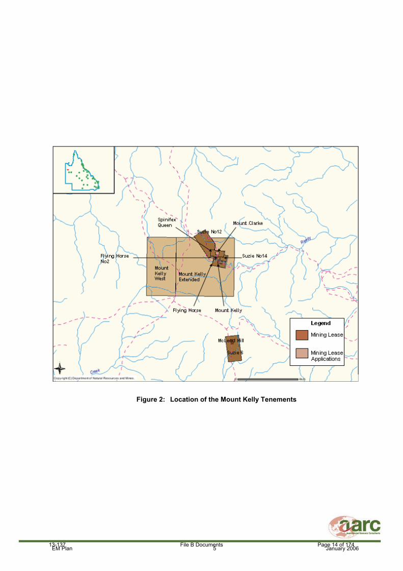
Table 2 describes the details of the new MLAs to be added to the Project and Figure 2 shows the locations of these tenements.
Table 2: MLAs to be added to the Mount Kelly Project
Tenement Name Holder Expiry Area (Ha)
MLA 90168 Mount Clarke Reefway - 4.05
MLA 90170 Mount Kelly Extended
Reefway - 1,118
MLA 90169 Mount Kelly West
Savannah - 644
Total Area 1,766.05
13-137 File B Documents Page 13 of 174
EM Plan 5 January 2006
Figure 2: Location of the Mount Kelly Tenements
13-137 File B Documents Page 14 of 174

EM Plan 6 January 2006
2.3 RELEVANT STAKEHOLDERS
The Project is relatively isolated and is located in a sparsely populated rural area typified by large land holdings where the surrounding land use is predominantly cattle grazing. The nearest non-Project related residences to the Project are approximately 30 km away as shown in Figure 3. Stakeholders and other groups or individuals with an interest in the operations include surrounding neighbours, Mount Isa City Council and State government departments, including Department of Natural Resources and Mines (DNRM) and the QEPA.
CopperCo Limited has conducted extensive consultation with Native Title groups and will continue to do so as part of a proactive community consultation program and development of a Cultural Heritage Management Plan (Milestone 3). CopperCo Limited also plans to undertake community consultation with relevant landholders in the region and will do so in the near future.
Relevant government agencies, stakeholders and the general community will have a chance to comment or object to the Project as part of the QEPA approval process. The QEPA will seek relevant advice and comment from experts and government agencies as part of assessing this EM Plan and setting the conditions of the draft EA. Once a draft EA has been issued for the Project by the QEPA, a public notice will be advertised in relevant newspapers and a public objection period commenced for at least 20 business days.
Considering the distance of the Project to the nearest residences, as well as the air, water, land management, waste management and noise control strategies outlined in this document, little or no impacts on the amenity and liveability of the area, access to services, and health and well-being of the community is expected.
The operations will have a positive impact on the economy of the local region and the state through payment of rates, purchase of consumables, use of service industries and payment of royalties and taxes. Community consultation with affected landholders will continue to be carried out as required throughout the life of the mine.
13-137 File B Documents Page 15 of 174

EM Plan 7 January 2006
Figure 3: Location of Nearest Residences to the Project
Mount Kelly
13-137 File B Documents Page 16 of 174

EM Plan 8 January 2006
2.4 REAL PROPERTY DESCRIPTION AND CURRENT DISTURBANCE TYPES
Real Property Descriptions (Lot and Plan details) for land situated under the Project tenements are detailed in Table 3 below.
Table 3: Real Property Descriptions for Project Tenements
Mining Tenure ID
Name of Lease Underlying Tenures
Registered Lessees
Registered Place of Business
ML 5426 McLeod Hill Lot 5 on CP 865892
Calton Hills Pty Ltd Calton Hill Pastoral Lease Barkly Highway Mt Isa QLD 4825
ML 5435 Mt Kelly Lot 5 on CP 865892
Calton Hills Pty Ltd Calton Hill Pastoral Lease Barkly Highway Mt Isa QLD 4825
ML 5446 Flying Horse 1 Lot 5 on CP 865892
Calton Hills Pty Ltd Calton Hill Pastoral Lease Barkly Highway Mt Isa QLD 4825
ML 5447 Spinifex Queen Lot 5 on CP 865892
Calton Hills Pty Ltd Calton Hill Pastoral Lease Barkly Highway Mt Isa QLD 4825
ML 5448 Flying Horse 2 Lot 5 on CP 865892
Calton Hills Pty Ltd Calton Hill Pastoral Lease Barkly Highway Mt Isa QLD 4825
Lot 5 on CP 865892
Calton Hills Pty Ltd Calton Hill Pastoral Lease Barkly Highway Mt Isa QLD 4825
ML 5474 Suzie 6
Lot 2 on SP 162421
Calton Hills Pty Ltd Calton Hill Pastoral Lease Barkly Highway Mt Isa QLD 4825
ML 5476 Suzie 12 Lot 5 on CP 865892
Calton Hills Pty Ltd Calton Hill Pastoral Lease Barkly Highway Mt Isa QLD 4825
ML 5478 Suzie 14 Lot 5 on CP 865892
Calton Hills Pty Ltd Calton Hill Pastoral Lease Barkly Highway Mt Isa QLD 4825
MLA 90168 Mount Clarke Lot 5 on CP 865892
Calton Hills Pty Ltd Calton Hill Pastoral Lease Barkly Highway Mt Isa QLD 4825
MLA 90170 Mount Kelly Extended
Lot 5 on CP 865892
Calton Hills Pty Ltd Calton Hill Pastoral Lease Barkly Highway Mt Isa QLD 4825
MLA 90169 Mount Kelly West
Lot 5 on CP 865892
Calton Hills Pty Ltd Calton Hill Pastoral Lease Barkly Highway Mt Isa QLD 4825
13-137 File B Documents Page 17 of 174

EM Plan 9 January 2006
Current land disturbance on the Project is related to mineral exploration and cattle grazing and includes access roads, exploration tracks, drill pads and a small exploration camp. There has been some minor historic mining at Mount Clarke.
2.5 ENVIRONMENTALLY SENSITIVE LOCATIONS
There are currently no Category A, B or C Environmentally Sensitive Locations within the Project area or immediately surrounding the Project. The Environmentally Sensitive areas map as obtained form the QEPA website (http://www.epa.qld.gov.au/ecoaccess/ecomaps) is shown in Figure 4.
13-137 File B Documents Page 18 of 174

EM Plan 10 January 2006
Figure 4: Environmentally Sensitive Areas Map
13-137 File B Documents Page 19 of 174
Released

EM Plan 11 January 2006
2.6 WILD RIVERS LEGISLATION
The Queensland Parliament passed the Wild Rivers Act 2005 in October 2005. The purpose of the Act is to preserve the natural values of wild rivers. It does this by regulating most future development activities within a declared wild river and its catchment area. A wild river is a river system that has all, or almost all, of its natural values intact. For example, its flow regime, sediment regime and water quality will be in a near natural condition and it will have healthy riparian vegetation and connected wildlife corridors. These natural values provide the basis for sustaining healthy ecological processes in rivers and support the habitat needed for diverse native plant and animal communities. They also provide scenic and recreational appeal.
The Project tenements are located within the catchments of the Leichhardt and Georgina Rivers. Neither of these catchments are currently declared or nominated for declaration under the Wild Rivers Act 2005. Therefore the mining activities on the Project tenements will have no impact on areas nominated or declared as wild rivers.
There are two options for the water supply for the Project. The preferred strategy is to obtain water from the Greenstone Creek Dam (Waggaboonya Dam) located at Mount Gordon Mine via a pipeline to the Project. This dam is already constructed with an approved water supply allocation which may be sufficient for both the needs of the Mount Kelly Project and the Mount Gordon Mine. An assessment of this water supply option is currently being undertaken to determine allocations and feasibility. If required, further licences or permits will be sought from DNRM. The Greenstone Creek Dam is located within the Leichhardt River catchment and therefore would not have any impact on nominated or declared wild rivers.
The second water supply option is to obtain water by developing the Thorntonia Borefield which is located 65 km north of the Mount Kelly Project. Water licences and permits will be applied for if this water supply option is pursued. The proposed Thorntonia Borefield is located within the Gregory River catchment which has been nominated under the Wild Rivers Act 2005. The Wild Rivers Act 2005 states that “No more than one percent of water will be allowed to be drawn from wild rivers, which ensures the protection of wetlands, waterholes and floodplains”. Klohn Crippen (water consultants for the Project) have estimated that the water requirements from the Thorntonia Borefield for the Project (1.1 GL/annum or 35L/s) would amount to 0.16 – 0.29% of the median to average Gregory River flows, which is below the 1% limit.
13-137 File B Documents Page 20 of 174

EM Plan 12 January 2006
3.0 DESCRIPTION OF THE EXISTING ENVIRONMENT
There are a number of baseline environmental studies that have been conducted for the Mount Kelly and Lady Annie Project sites. These studies aim to document and assess the current state of the Project area and surrounds, highlight any areas of potential environmental impact from the Project and propose mitigation strategies where required. Baseline studies for the Project include the following reports of which most are contained in Volume 2 and 3 of this EM Plan:
Soils and Land Use Suitability Study (AARC, December 2005 – Appendix A);
Flora and Fauna Assessment (AARC, December 2005 – Appendix B);
Stream Sediment and Morphology Study (AARC, December 2005 – Appendix C);
Draft Project Feasibility Report (Klohn Crippen, 2005) – covers hydrology, hydrogeology and geotechnical information for the Project and will be submitted to the QEPA when the final report is available;
Waste Rock Characterisation Report (AARC, December 2005 – Appendix D);
European Cultural Heritage Study (Gordon Grimwade and Associates, December 2005 – Appendix E); and
Environmental Risk Assessment (AARC, December 2005 – Appendix G).
A summary of the relevant aspects of the Project site and the above baseline studies is provided in the following sections.
3.1 REGIONAL CLIMATE
Information from the Australian Bureau of Meteorology indicates that the average annual rainfall for Mount Isa is approximately 451.9 millimetres (mm). Rainfall is typically highly seasonal, with the dry season peaking around June (average 3.5 mm) and the wet season peaking in January and February (average 109.5 mm and 101.3 mm in each of these months respectively).
The coldest average temperatures occur in July (24.6 degrees Celsius [°C]) and the hottest average temperatures occur in January (36.4°C).
3.2 GEOLOGY
The host rocks for the oxide copper mineralization at the Mount Kelly/Flying Horse deposits are principally dolomitic siltstones and sandstones. Minor cherty/silicious bands are present. The dolomitic siltstones/sandstones are extremely weathered and friable and contain occasional carbonate bands.
At Mt Clarke, the ore body outcrops and as a result, little pre-stripping will be required. The wall rocks in both deposits comprise similarly weathered dolomitic siltstones and sandstones but are slightly more competent than the overburden material.
The presence of carbonate/dolomite bands and the extremely weathered and kaolinised character of the overburden and the surrounding wall rocks suggest that the waste rock material is highly likely to be net acid consuming. From all the drilling completed to date, sulphides are rare to absent above the base of complete oxidation. Given the heavily oxidised state of the overburden and wall rocks, the waste rock is expected to be net acid consuming.
13-137 File B Documents Page 21 of 174

EM Plan 13 January 2006
3.3 SOIL AND LAND USE SUITABILITY
A Soil and Land Suitability Study for the proposed Lady Annie and Mount Kelly Project Sites was undertaken by AARC in 2005. The following is a summary of the major findings of the assessment, the full report is contained within Appendix A.
The aim of the study was to determine soil types, their physical and chemical characteristics and to determine their agricultural land suitability prior to mining.
Soils across the Project Sites were assessed at a total of 66 locations during a four-day field survey, conducted from 14th – 17th September, 2005. At the completion of the field survey, the soil samples were packaged for transportation to a laboratory (Incitec-Pivot, in Werribee Victoria) for chemical and physical analysis.
The soils within the Project Sites, due to their shallow, skeletal nature and lack of significant soil development, have been broadly classified as Rudosols/Tenosols (Australian Soil Classification, Isbell 1996) which are equivalent to Lithosols under the Great Soil Group classification (Stace et al 1968). The soil profiles exposed have an indicated soil depth of 10 – 20 cm. Soils in the steeper parts of the Project Sites and on the crests of the hills are typically very shallow with many of the slopes dominated by resistant iron-manganese rich scree.
Based on the field assessment, the Project Sites contain five distinct soil types ranging from cracking/slumping clays to sandy loams and clay loams. Soils are generally slightly acidic to neutral, shallow and low in nitrogen and phosphorous. Salinity levels in the soils are below the land use management criteria, suggesting a negligible plant response to levels in the soil.
The five distinct soil types include:
Soil Type 1: Brownish to reddish clay loam/loam soils, with a granular A horizon mostly found on hills and ridges, associated with Spinifex, Snappy Gum and Lancewood.
Soil Type 2: Greyish/brown skeletal soils found on hills and ridges associated with Lancewood community on the western side of Lady Annie.
Soil Type 3: Shallow, stony, loamy, yellow/whitish/grey dolomite/kaolinite orientated soils, found on plateaus associated with the southern area of Mount Kelly Extended. Snappy Gum, Ghost Gum and Lancewood are associated with this soil type.
Soil Type 4: Deeper more developed grey/brown soil, greater levels of organic matter, loamy to clay loam in the B horizon, situated on plains and undulating plains. Snappy Gum, Lancewood and Bloodwood communities
Soil Type 5: Cracking/slumping clay soil found on the Mt Kelly West area. Brown to orange slumping coloured clays. The soil is associated with the Gidgee and Sugar Box vegetation communities.
Given the post mine land use is most likely to be grazing which may or may not be improved, topsoil that has been stockpiled on the Project Sites may need to be fertilised after stockpiling for use as effective grazing country. As soils are low in organic matter, <1.5% (Guidelines for Agricultural Land Evaluation in Queensland, QDPI 1990), stockpiling of topsoils will need to be managed so as to reduce the loss of organic carbon through stockpiling.
The five soil types have been mapped into four distinct Soil Mapping Units, described as Lowland, Mesa, Gidgee and Sandstone. Generally each Soil Mapping Unit has similar management
13-137 File B Documents Page 22 of 174

EM Plan 14 January 2006
requirements. The distribution of Soil Mapping Units over the Mount Kelly Project areas is shown in Figures 5 and 6.
Figure 5: Distribution of Soil Mapping Units on the Mount Kelly Extended MLA
13-137 File B Documents Page 23 of 174

EM Plan 15 January 2006
Figure 6: Distribution of Soil Mapping Units on the Mount Kelly West MLA
13-137 File B Documents Page 24 of 174

EM Plan 16 January 2006
An interpretation of the data collected on the physical, chemical and nutrient characteristics of the Soil Mapping Units has been used to rank the land-use according to a five-class system that applies to grazing, rain fed cropping and conservation. This assessment is used to assess the suitability of the land for any potential land-use.
The land suitability classes are described as:
Class 1 Suitable land with negligible limitations which is highly productive requiring only simple management practises to maintain economic production.
Class 2 Suitable land with minor limitations which either reduce production or require more than the simple management practices of Class 1 land to maintain economic production.
Class 3 Suitable land with moderate limitations which either further lower production or require more than those management practices of Class 2 land to maintain economic production.
Class 4 Marginal land with severe limitations which make it doubtful whether the inputs required to achieve and maintain production outweigh the benefits in the long term (presently considered unsuitable due to the uncertainty of the land to achieve sustained economic production).
Class 5 Unsuitable land with extreme limitations that preclude its use for the proposed purpose.
The Soil Mapping Units identified on the Projects Sites have been assessed as having the following pre-mining suitability for grazing and rain fed broad-acre cropping as shown in Table 4.
Table 4: Pre-Mining Land Suitability for Soil Mapping Units
Pre-Mining Land Suitability Soil Mapping Units Grazing Rain Fed Broad Acre Cropping
1: Lowland 4 4 2: Mesa 5 5 3: Sandstone 5 5 4: Gidgee 4 4
The Gidgee and Lowland Soil Mapping Units are considered to be marginally suitable for beef cattle grazing but would require major inputs to ensure continuing sustainability while the Sandstone and Mesa units have been determined to be unsuitable for grazing due to limitations of low plant available water capacity, lack of nutrients and erodibility. The area is also severely constrained for use for rain fed cropping due primarily to low plant available water capacity, low levels of nutrients, excessive rockiness, topography, erosion and physical constraints.
3.4 FLORA AND FAUNA
AARC conducted a Flora and Fauna Assessment of the proposed Lady Annie and Mount Kelly Copper Projects in 2005. The following is a summary of the major findings of the assessment and the full report is contained within Appendix B.
To assess the environmental values of flora and fauna communities on the Project Sites, AARC undertook the following scope of works:
13-137 File B Documents Page 25 of 174

EM Plan 17 January 2006
A literature and database review to identify species of conservation significance known from the region. This enabled these species to be targeted during the field survey component of the study;
A field survey employing standard methodologies to determine the composition of flora and fauna species inhabiting the Project Sites, particularly species of conservation significance2; and
The preparation of a report to CopperCo Limited describing significant environmental features and outlining possible management strategies to reduce any foreseeable impacts associated with the proposed activities.
3.4.1 Field Survey Methods
Site scoping of the Project Sites was conducted using aerial photography and broad ground truthing on the first day of the survey period. Transects were located in areas representative of regional vegetation types and habitats. In addition, habitats potentially inhabited by species of conservation significance were targeted. Site scoping also allowed for the identification of boundaries of Regional Ecosystems, so that 1:25,000 mapping of the Regional Ecosystems could be produced.
In order to map vegetation communities, Quaternary plots were used along the boundaries of vegetation communities or to confirm the extent of the community. The quality of communities was assessed with regard to their likely value and viability as a representative vegetation type.
Survey methods for fauna included the establishment of four monitoring transects in representative areas of habitat on the Project Sites. Numerous trapping and survey techniques were employed along these transects including pitfall trapping, hair funnel sampling, Elliot trapping, bat call recording, habitat searching, and spotlighting. The ANABAT echolocation recording system was the primary method employed to survey microbats at the Project Sites. The ANABAT system was deployed for one entire night at each of the four fauna transects with additional incidental recordings made at other areas of interest on the Project Sites. This method therefore represents a broad census technique which facilitates the detection of a broad suite of microbats which utilise the Project Sites.
Fauna records obtained from the monitoring transects were combined with incidental records from other areas to produce a fauna species list for the Project Sites.
3.4.2 Field Results
Flora
Five major vegetation communities were identified on the Project Sites during the AARC survey. These communities and their conservation status are summarised in Table 5. The same vegetation community occurring on different geologies has a different Regional Ecosystem equivalent and therefore some communities will have multiple Regional Ecosystems assigned against them.
2References to “Species of Conservation Significance” or “Threatened Species” in this report refer to those species listed as Rare, Vulnerable, Endangered or Critically Endangered under the Nature Conservation Wildlife Regulation 1994 or Environmental Protection and Biodiversity Conservation Act 1999.
13-137 File B Documents Page 26 of 174

EM Plan 18 January 2006
Table 5: Vegetation Communities Identified on the Project Sites
Vegetation Community Regional
ecosystem equivalents
VMA (1999) status
QEPA Biodiversity status
1.11.2 Not of Concern Of no concern at present
1.7.1 Not of Concern Of no concern at present
1.5.3 Not of Concern Of no concern at present
Snappy Gum Open Woodland
1.10.4 Not of Concern Of no concern at present
1.7.1a Not of Concern
Of no concern at present
1.11.2x2a Not of Concern
Of no concern at present
Lancewood Open Forest
1.10.5 Not of Concern Of no concern at present
1.7.2 Not of Concern Of no concern at present
1.5.5 Not of Concern Of Concern
1.5.4x1 Not of Concern Of Concern
Sugar Box Open Woodland
1.11.4 Not of Concern Of Concern Gidgee Open Woodland 1.5.8 Not of Concern No Concern at
Present River Redgum Riparian Woodland 1.3.7 Not of concern Endangered
Vegetation disturbance on the Project will impact upon vegetation communities that are “Not of Concern” under both the Vegetation Management Act 1999 and Queensland Environmental Protection Agency Biodiversity Status. These communities are very wide spread throughout the region and the relatively small losses that will occur will have a limited ecological impact.
River Red Gum Riparian Woodland is listed as being “Endangered” under the Queensland Environmental Protection Agency Biodiversity Status due to other threatening processes other than land clearing. These processes include inappropriate fire regimes, weed invasion and grazing. The presence of large hollow bearing trees and physical protection to riverine systems is of high ecological value and the destruction of these habitats should be limited. No known areas of this Endangered Regional Ecosystem are planned to be cleared on the Project.
The nearest River Red Gum Riparian Woodland is at least 1.2 km from any open cut pit on the Project. The River Red Gum community is located within a separate geological unit from the ore deposits and is not located near the Mount Kelly Fault (the major source of groundwater inflow within the pit area). The majority of dewatering impact is expected within the Mouth Kelly fault system, and therefore it is
13-137 File B Documents Page 27 of 174

EM Plan 19 January 2006
considered unlikely that dewatering of the Mount Clarke and Mount Kelly/Flying Horse pits will impact significantly on groundwater levels in the area of the River Red Gum community.
No flora species of conservation significance were found on the Project Sites, despite detailed searches in areas of suitable habitat. However, Brachychiton collinus was observed close to the ML boundaries. Modelling of the potential occurrence of this species and targeted on ground searches suggest that there is very little likelihood that the proposed activities will have any effect on this species.
No species declared under the Land Protection (Pest and Stock Route Management) Act 2002 or other weed species of management concern were recorded during the survey.
Fauna
A total of 115 vertebrate fauna species were identified on the Project Sites, comprising three amphibians, 19 mammals, 17 reptiles, and 76 birds. Four introduced species were identified including two that are listed as Class 2 pests under the Land Protection (Pest and Stock Route management ) Act 2002.
One bird of conservation significance was recorded from the Project Sites, the Carpentarian Grasswren (Amytornis dorotheae). From a review of previous fauna surveys one other bird species of conservation significance is known from the Project Sites, the Pictorella Mannikin (Heteromunia pectoralis).
Section 7.2.3.3 of Appendix B of this EM Plan deals with birds of conservation significance. The report suggests limited impact because extensive areas of suitable habitat are available on the Project Site and although suitable habitats will be disturbed, it is unlikely that this will have a significant effect on the regional population of the species. Additional information on the Carpentarian Grasswren is provided below.
Carpentarian Grasswrens live on sandstone outcrops in Triodia Hummock Grassland and Low Open Woodland, with or without a low shrubby understorey (McKean and Martin, 1989, Rowley and Russell, 1997). They prefer long-unburnt hummock grass, the rugged terrain in which they occur offering natural protection from fire. They forage on the ground for insects and seeds, and lay 2-3 eggs in domed nests built in Triodia clumps (Beruldsen, 1980, Rowley and Russell, 1997).
Carpentarian Grasswrens eat insects and seeds, however their foraging ecology is poorly known. There is not a lot of information available about their breeding cycle as there have been no studies conducted to date. Nests are located above the ground, embedded in the upper portion of clumps of Spinifex. Active nests have been recorded in January and September, although it is suggested that most birds lay eggs between November and March (after the start of the wet season).
There are extensive areas of suitable habitat across the Project site and within the region (Snappy Gum Woodland with Spinifex understorey). Approximately 60% of the Project site constitutes this habitat type. Whilst areas of suitable habitat on the Project site may be disturbed as part of the proposed mining activities, it is unlikely that this will have a significant effect on the regional population of the species.
A total of eight migratory bird species, as listed under the Environmental Protection and Biodiversity Conservation Act 1999, were observed on the Project sites.
As Table 6 demonstrates, the distribution of the EPBC listed migratory bird species observed during the CopperCo field survey are widespread throughout Australia. Accordingly, the local populations of these Migratory Species on the Project Site are unlikely to constitute an ‘ecologically significant proportion’ of the total populations of the species. Furthermore, the Project Sites are not at the limit of any of the eight
13-137 File B Documents Page 28 of 174
Released

EM Plan 20 January 2006
Migratory Species ranges, nor are any of the species considered to be declining within the region. Therefore, the Project Site does not constitute “important habitat” for any of the eight observed Migratory Species.
Table 6: Environment Protection and Biodiversity Conservation Act 1999 listed Migratory Bird Species Observed by AARC Ecologists During the Copper Co Fauna Survey (2005).
Three mammal species of conservation significance were identified on the Project sites, the Purple-necked Rock Wallaby (Petrogale purpureicollis), Little Pied Bat (Chalinolobous picatus) and Troughton’s Sheathtail Bat (Taphozous troughtoni). One species of significance had previously been positively recorded from nearby Lady Annie, the Northern Leaf-nosed Bat (Hipposiderus stenotis). This species was recorded from the old Phosphate Pit located to the northeast of the Lady Annie Lease by James Warren and Associates (2000).
Bat habitat in the form of a mine adit was identified in an area of proposed disturbance at Mount Kelly/Flying Horse and AARC have been informed that it will be destroyed when mining commences. The adit is a relic of previous mining processes and therefore does not constitute a natural habitat. There are no other known adits located on the Project.
Other potential roost sites, particularly caves, may however occur on the Project. It is envisioned that some of these caves will be destroyed during the mining process. Prior to commencement of any mining activity, a suitably qualified Ecologist will conduct a survey of caves within the area of disturbance to determine if there are any habitats of conservation significance.
Following a review of the proposed activities on the Project Sites and an assessment of the habitat types and availability, it is considered that there will be no significant impact upon the local populations of any of these threatened mammal species.
As there are no foreseeable significant impacts upon any Nationally Significant threatened species on the Project Sites, the project does not need to be referred to the Commonwealth Department of Environment and Heritage.
Scientific Name Common Name Distribution
Accipter fasciatus Brown goshawk Widespread in Australia
Aquila audax Wedge-tailed eagle Widespread in Australia
Elanus axillarus Black-shouldered kite
Moderately common in Cloncurry, Richmond district and areas around Mt Isa
Haliastur sphenurus Whistling kite Widespread in Australia
Milvus migans Black kite Widespread in Australia
Falco berigora Brown falcon Widespread in Australia
Falco cenchroides Nankeen kestrel Widespread in Australia
Merops ornatus Rainbow bee-eater Widespread in Australia
13-137 File B Documents Page 29 of 174

EM Plan 21 January 2006
3.5 STREAM SEDIMENT AND MORPHOLOGY STUDY
A Stream Sediment and Morphology Study for the proposed Lady Annie and Mount Kelly Project Sites was conducted by AARC in 2005. The following is a summary of the major findings of the study and the full report is contained within Appendix C.
The aims of the survey were to report on the following:
Stream sediment quality of the various streams across the Project Sites to support the setting of receiving stream sediment quality criteria for the Project Sites;
Morphological characteristics of watercourses on the Project Sites;
Detail mitigation strategies to prevent potential negative impacts of the Projects on streams downstream of mine workings and infrastructure; and
Describe a recommended ongoing monitoring program.
The Project Sites are situated mainly in the upper part of the Gunpowder Creek catchment, which is a major tributary of the Leichhardt River. The Leichhardt River flows in a northerly direction to the Gulf of Carpentaria. Gunpowder Creek has a catchment area of approximately 3,600 km2.
The Project Sites are crossed by a number of small ephemeral streams, which generally drain in a southerly to easterly direction towards Gunpowder Creek. There are no permanent natural surface waterbodies on the Project Sites.
Baseline data on the morphology and stream sediment quality of watercourses on the Project Sites was collected during a four-day field survey, conducted from 14th – 17th September, 2005.
Overall, the condition of the streams on both the Lady Annie and Mount Kelly Project Sites appear to be good with little evidence of mass sediment movement or erosion. In most cases, where erosion has occurred it appears to have been part of the natural erosion and deposition cycle of the system.
Levels of cadmium, antimony, silver and mercury were all below detectable limits for the sediments sampled within the Mount Kelly Project Site.
Levels of chromium, lead, nickel, zinc, and arsenic were detectable within the Mount Kelly Project Site, however all samples were below the Australia and New Zealand Guidelines for Fresh and Marine Water Quality (ANZECC) 2000 Aquatic Ecosystem default low trigger limits.
Copper levels on the Mount Kelly Site were approaching the low trigger value at Site 6. This high level is expected to be due to the sampling locations being close to the naturally mineralised copper deposit area.
Based on the ANZECC Aquatic Ecosystem guidelines 2000 the low and high trigger values for copper should be adjusted to be site specific. This low trigger value has been adjusted to 80% of twice the maximum background level and the high trigger value has been adjusted to twice the existing maximum background level (QEPA 2003).
A summary of the results is presented in Table 7 and the locations of the samples sites are shown in Figure 7.
13-137 File B Documents Page 30 of 174

EM Plan 22 January 2006
Table 7: Stream Sediment Quality Results – Mount Kelly Project
SITE NUMBER ANZECC Triggers
1 2 3 4 5 6 Low Trigger
High Trigger
Antimony <5 <5 <5 <5 <5 <5 2 25 Arsenic 8 <5 <5 <5 6 <5 20 70 Cadmium <1 <1 <1 <1 <1 <1 1.5 10 Chromium 22 10 14 48 31 14 80 370 Copper 32 19 20 10 7 61 100 120 Lead 10 <5 <5 6 7 5 50 220 Nickel 10 3 4 3 4 6 21 52 Silver <2 <2 <2 <2 <2 <2 1 3.7 Zinc 16 <5 <5 <5 5 6 200 410 Mercury <0.1 <0.1 <0.1 <0.1 <0.1 <0.1 0.15 1
The shaded values indicate adjusted low and high trigger values based on site specific data, adjusted to the nearest 10.
In order to not adversely affect the natural processes within the streams on the Project it is recommended that any land disturbance within streams beds and adjacent to their bank should be kept to a minimum and stabilised immediately on completion of works. All major land disturbances on the Project that may have the potential to produce soil erosion or excessive sediment during storm events (i.e. waste rock dumps) should be drained via sediment traps to drop out suspended sediment prior to discharge of stormwater to natural stream systems. Progressive rehabilitation of land disturbances during the Project life should be undertaken where possible to reduce the potential for excessive sediment loads from disturbed land.
An annual monitoring program should be implemented, sampling streams both downstream of any mining or infrastructure disturbances and some upstream sites to take into account any natural variations in stream sediment quality and morphology.
For all metals besides copper, the ANZECC Aquatic Ecosystems guidelines should be used for the low and high triggers when setting downstream stream sediment values for the Project Sites. For copper, site specific low and high trigger values as determined from background data in the Stream Sediment and Morphology Study report should be used.
13-137 File B Documents Page 31 of 174
Released

EM Plan 23 January 2006
Figure 7: Stream Sediment Sampling Sites Mount Kelly
13-137 File B Documents Page 32 of 174

EM Plan 24 January 2006
3.6 SURFACE WATER AND DRAINAGE
The Project occurs on the top of a catchment divide for two major ephemeral river systems. Water drainage on the majority of Project drains in an easterly direction towards Reedy Creek and its tributaries, which then flow north-east into Gunpowder Creek and eventually to the Leichhardt River. Surface water drainage from the Mount Kelly West MLA drains to the north in the northern portion of the lease in tributaries which form Battle Creek which also eventually joins Gunpowder creek.
A portion of the south of the Mount Kelly West MLA drains to the south-west through Saga Creek, which joins Inca Creek and Buckley River in the Georgina River Catchment.
Surface water drainage and diversions on the Project have been assessed by Klohn Crippen in their Draft Feasibility Report (2005) and is described below.
The philosophy behind the surface water management plan for the Project is to minimise contact of runoff water with mining operations. Where possible, stormwater runoff will be diverted around operations and allowed to continue on its natural drainage path, minimising both disturbance to the environment and the volume of water that contacts the area disturbed by mining. Stormwater runoff that comes in contact with mining operations will be collected, monitored and treated as required prior to release back to the environment or alternatively used as process water. As recommended in the DNRM Site Water Management guidelines (DNRM 1995), section 8.4.4, sedimentation dams will be used to remove suspended solids from runoff water. Runoff from areas which will contain hazardous materials, such as the heap leach pad, will be required to be contained in ponds with a Design Storage Allowance (DSA), as recommended in the DNRM guidelines. Keeping the hazardous runoff separate from other stormwater runoff will minimise the DNRM storage allowance requirements for the site.
3.6.1 Plant Site
The topography of the proposed processing area on the Mount Kelly West MLA is relatively flat with only one minor, poorly defined tributary of Saga Creek traversing this area. It is believed that rainfall across this area would generate minimal stormwater runoff, with most rainfall evaporating or infiltrating into the soil. Due to the flat topography of the process plant area and the lack of any major natural drainage paths, it is not considered necessary to divert any natural waterways around the site. Runoff from the surrounding catchment into the site will be minimal and will be picked up by drainage bunds and drains around major processing infrastructure and deposited downstream.
3.6.2 Mount Clarke Mining Area
Five sub-catchments were identified having drainage paths entering the Mount Clarke pit. All the sub-catchments are small and are not expected to produce significant runoff volumes. Construction of diversion channels around the perimeter of the pit will reduce the risk of stormwater runoff from entering the pit. Peak stormwater runoff flows have been calculated for these sub-catchments using the rational method as outlined in ‘Australian Rainfall & Runoff’.
Sub-catchment A has an area of 4.2 ha and has an expected 10 year peak runoff flow of 0.7 m3/s. As this catchment is located between two large knolls on the pit boundary, construction of a drainage channel would involve significant earthworks compared to the volume of stormwater. It is proposed for this catchment to direct runoff flows into the pit drainage system where they will be pumped from the pit sump to the Mount Clarke Pit Sediment Dam; alternatively an evaporation pond could be constructed on the drainage path to reduce runoff through evaporation.
The sub-catchment B has an area of 1.3 ha and an expected 10 year peak runoff flow of 0.3 m3/s. The existing drainage path runs along the edge of the proposed pit and minimal earthworks would be
13-137 File B Documents Page 33 of 174

EM Plan 25 January 2006
required to realign this channel to the perimeter of the pit to allow runoff to continue without contamination from mining operations.
Sub-catchment C has an area of 0.9 ha and has an expected 10 year peak runoff flow of 0.2 m3/s. The sub-catchment D has an area of 1.3 ha and has an expected 10 year peak runoff flow of 0.3 m3/s. Both sub-catchment C and D are small and runoff from these will be short and peaky following a rain event. Construction of a diversion channel running north along the pit boundary will intercept these flows and divert them around the pit. The sub-catchment E has an area of 3.3 ha and has an expected 10 year peak runoff flow of 0.8 m3/s. The perimeter drain will pick up flows from this catchment and direct them to the existing waterway north of the pit.
3.6.3 Mount Kelly/Flying Horse Mining Area
Eight sub-catchments were identified as having drainage paths entering the Mount Kelly/Flying Horse pit. The majority of the sub-catchments are small and are not expected to produce significant runoff volumes. Construction of diversion channels around the perimeter of the pit will reduce stormwater runoff entering the pit.
Sub-catchment A has an area of 8.1 ha and has an expected 10 year peak runoff flow off 1.5 m3/s. However, this catchment would also receive flow diverted away from the Mount Clark Pit which would bring the 2 year peak run off to 1.2 m3/s and the 10 year peak run off to 1.7 m3/s. A diversion channel running between the two segments of the Mount Kelly/Flying Horse pit would be the most effective way of diverting this flow from the pit.
Sub-catchments B, C and D have a combined area of only 1.5 ha and a 10 year peak flow of 0.3 m3/s. As these sub-catchments are small and steep, the runoff will be short and peaky following a rain event. The diversion for these catchments will join into the drain from sub-catchment A and run between the two segments of the Mount Kelly/Flying Horse pit. The sub-catchment E has an area of 10.7 ha and an expected 10 year peak runoff flow of 1.9 m3/s. Earthworks would be required to realign this channel to the perimeter of the pit to allow runoff to continue without contamination from mining operations.
Sub Catchments F and G are small catchments having areas of only 1.4 ha and 0.5 ha respectively. The combined 10 year peak runoff flow of these two catchments is 0.5 m3/s and will be diverted into the perimeter drain and into the natural waterway to the south of the pit.
The sub-catchment H has an area of 3.2 ha and has an expected 10 year peak runoff flow of 0.6 m3/s. This flow will be directed into the pit perimeter drain and then into the natural drainage channel to the south.
3.6.4 Sediment Dams
Runoff from the waste rock dumps and ROM Pads will be intercepted by toe drains around the perimeter of the dumps and directed to sediment dams. It is expected that the runoff water quality from the waste rock dumps will be of a suitable quality for release, as investigations on the waste rock material have identified that it is non-acid producing. Runoff from surrounding catchments will be diverted around the waste rock dumps and ROM Pads and allowed to continue in the natural watercourse. It may be necessary to line these channels in places with rock riprap where expected velocities are greater than 2 m/s.
Sizing of the sediment dams is based on a 1 in 10 year ARI storm event with a one hour duration (the time of concentration for the catchments of the sediment traps). This storm event is recommended in the DNRM guidelines (DNRM 1995) for the design of sedimentation dams. Rainfall from a 1 in 10 year ARI 1 hour event will be 52.7mm. The standing water level in these dams will be at a depth of around 1m with the design freeboard for events around 2m
13-137 File B Documents Page 34 of 174

EM Plan 26 January 2006
Each sediment dam will have a filtered pipe as a primary outlet from the pond for gradual release of collected water over a 48 hour period. The outlet pipe will run through a wet well manhole beside the downstream channel where a Rising Stream Sampler will be mounted. Each pond will be provided with an overflow spillway to cater for storm events greater than the 1:10 year design storage event.
The locations of the proposed sediment dams/ponds on the Project are shown in Figures 8 and 9. The coordinates for the end of pipe releases from each of the sediment dams/ponds is described in Table 15.
3.6.5 Surface Water Quality
There is currently no background surface water quality data for the streams on the Mount Kelly Project leases although a background water quality monitoring program is being implemented for the current wet season. Therefore it is expected that some background water quality data for the Project will be available before the EA conditions for the Project are finalised.
In Lieu of this site specific data, water quality at the nearest DNRM gauging stations has been obtained from Greenstone Creek Site 1 (station 9130010), Greenstone Creek Site 2 (station 9130011) and Gunpowder Creek (upstream of Mount Gordon Mine workings – station 9130002) this data is presented in Appendix F. The results of this monitoring are likely to be similar to the water quality expected on the Mount Kelly Project as these sites are all with the Gunpowder Creek catchment. The results of the water quality monitoring conducted at these sites comply with the ANZECC 2000 water quality limits for Livestock Drinking Water. When the data was compared to the trigger values in ANZECC 2000 for Aquatic Ecosystems (Table 3.4.1 of the guidelines) several parameters such as aluminium, copper and zinc did not comply with the trigger values. This is most likely due to local mineralisation of the area which is also likely to be the case on the Mount Kelly Project. Therefore for the purpose of setting surface water quality standards for the Project mostly ANZECC 2000 Livestock Drinking Water limits will be used and Aquatic Ecosystem trigger limits where appropriate.
3.7 GROUNDWATER
Klohn Crippen has prepared a Draft Feasibility Report for the Project. A summary of the main findings of the hydrology for the Mount Kelly Project area from this report is given below.
The Mt Clarke and Mount Kelly/Flying Horse deposits are hosted by three main formations; the Mount Oxide Chert Member, the Paradise Creek Formation and the Esperanza Formation. Results of the hydrogeological field program undertaken in the Mt Clarke area indicate that groundwater at this location is structurally controlled. Exploration drilling has recorded groundwater flows in drill holes that have intersected fault zones and associated fracturing. The majority of flows were observed from holes that intersect the northwest-southeast trending Mount Clarke fault. Prominent cross-cutting faults are present throughout the deposits, located adjacent to the proposed Mount Kelly/Flying Horse pit. It is assumed that the faulting in the vicinity of the Mt Clarke pit will display similar aquifer characteristics. Groundwater inflow is expected to be encountered during pit excavations, and therefore a dewatering strategy is required.
Groundwater levels measured in three bores indicate that the piezometric surface is relatively flat, with no strongly defined groundwater gradient. Recharge to the system would be dominated by incident rainfall infiltration along the fault planes exposed at the ground surface. No observable groundwater discharge mechanisms were identified.
Both drawdown and residual drawdown data for all three bores displayed an increase in gradient of the drawdown curve throughout the test. The increase in drawdown rate during late time testing indicated
13-137 File B Documents Page 35 of 174

EM Plan 27 January 2006
the extent of the aquifer system is restricted and water available from storage is limited, which has positive implication to mine dewatering requirements.
The conceptual hydrogeological model for the Mount Clarke and Mount Kelly/Flying Horse pit areas identified that groundwater flow and distribution is structurally controlled, predominantly by the Mount Kelly and Spinifex Faults. These prominent structures are intersected by the proposed Mount Kelly/Flying Horse pit therefore, the dewatering associated with the pit excavation will reduce the storage of water within this system. Minor faulting has been observed within the proposed Mount Clarke pit area and therefore minimal pit dewatering is expected. As a result, impact on adjacent groundwater users extracting from the groundwater storage associated with the Mount Kelly or Spinifex Faults may occur.
Registered bore data obtained from the DNRM groundwater bore database indicates that one bore (RN38531) has been installed within 5 km of the proposed pits (1.5 km from the pits). The registered bore details indicate that this bore was installed in 1972 as a water supply for the Mount Kelly mine from an application submitted by the mining lease holder (ML5781) at the time. The water level observed in this bore was 27.4 m below ground level, with an approximate yield of 1.6 L/s. As this bore was installed for the purpose of a water supply for the Mount Kelly mine operations in 1972, and due to this mine being no longer in operation, it is assumed that this bore has been abandoned. Based on the above information on the site hydrogeology and adjacent registered groundwater bore (RN38531), it is considered that the impact on the groundwater system as a result of the proposed dewatering of the Mount Clarke and Mount Kelly/Flying Horse pits should have minimal impact on adjacent groundwater users.
3.7.1 Groundwater Quality
A water quality sample was collected from one groundwater bore on the Project and analysed for pH, conductivity, redox potential, dissolved oxygen, alkalinity, major cations, major anions, dissolved metals and nutrients. The sample was slightly alkaline, with an EC level of 538μS/cm. The sample had a hardness value of 282mg/L as CaCO3, with the dominant cations being Ca2+ and Mg2+ and the dominant anion HCO3
-. Dissolved metal concentrations for all metals tested were either below the laboratory detection limit, or below the ANZECC (2000) water quality limits for Livestock Drinking Water. Copper levels in the sample (0.030mg/L) exceeded the ANZECC 2000 Aquatic Ecosystems trigger level for copper (0.0014mg/L). The EC of the sample also exceeded the ANZECC 2000 Aquatic Ecosystem limit of 250μS/cm.
3.7.2 Groundwater Dewatering
A groundwater model was used to estimate inflows into the Mount Clarke and Mount Kelly/Flying Horse pits. The model showed that inflows should be manageable without pre-production dewatering, using in-pit (sump) transfer pumping techniques. The model also showed that the extraction of water from the Mount Kelly/Flying Horse pit will have a dewatering impact on inflows into the Mount Clarke pit.
The main sources of water into the Mt Clarke pit will be precipitation and groundwater. Runoff from adjacent undisturbed catchments (B, C, D and E) will be diverted away from the pit. Groundwater flows into the pit are not expected to be significant, so water can be collected in a pit sump.
As with the Mount Clark pit, the main sources of water into the Mount Kelly/Flying Horse pit will be precipitation and groundwater. Runoff from adjacent undisturbed catchments will be diverted away from the pit. Groundwater flows into the pit are not expected to be significant, so water can be collected in a pit sump.
13-137 File B Documents Page 36 of 174

EM Plan 28 January 2006
Sump water from both pits will be pumped to sediment dams at surface level for settling and re-use as dust suppression water.
3.7.3 Heap Leach Area
Field investigations undertaken to assess the conceptual hydrogeology of the heap leach processing area comprised drilling and installation of three piezometers (to a depth of 30m) adjacent to the proposed heap leach area. No groundwater was encountered during drilling.
The geology across the plant site is relatively uniform comprising a felsic-rich, possibly quartzite, formation; with the deeply weathered profile extending below 50 m of natural surface. East of the plant site, lithology changes to an interbedded siltstone/mudstone formation with a weathered profile extending 30 m below the natural surface. Generally, the weathered profile underlying the plant site area comprises a mixture of kaolinitic and smectitic clays. Groundwater was not encountered within the weathered profile.
The site investigations did not intersect shallow groundwater resources, nor did it identify any shallow granular material with the potential to provide a seepage pathway away from the HL area. Furthermore, the deeply weathered nature of material below the proposed plant site is strongly dominated with clay and fine material. However, this interpretation is based on limited data only and does not account for localised zones of higher permeability that may exist beneath and away from the process plant site.
Generally, a shallow piezometric surface in similar shallow geological systems would reflect the topographic expression; therefore, groundwater flow would be similar to the surface drainage. Detailed topographic surveying of the site indicates a westerly drainage direction. Seepage pathways away from the heap leach pad would generally be radial in nature, or would follow any local preferential flow paths that may exist. This is because an artificial head induced by the heap leach pad would be significantly higher than current conditions and would dominate local groundwater flow. However, the heap leach pad design includes the installation of a liner to help prevent the occurrence of such conditions.
In the event some limited seepage loss does occur, the migration of the wetting front away from the Heap Leach area would be relatively slow due to the clay-rich nature of the weathered profile, which is estimated to range in permeability from 4 x 10⁻⁴
to 9 x 10⁻⁹ m/day.
Although groundwater was not encountered adjacent to the heap leach pads, three initial piezometers (LA-MB01, 02 and 03) have been installed to monitor upstream/background water quality (Figure 14). Each piezometer was constructed to a depth of 30m with the entire annulus gravel packed to surface. This construction design will enable interception of a wetting front (to a depth of 30 m) that may develop during operations. Additional piezometers will be required to compliment the three piezometers already installed and to provide suitable monitoring capacity for detection of potential seepages for the process plant area. Typical locations of these piezometers are shown in Figure 14 although these will need to be revisited once the final heap leach pad layout is confirmed. These piezometers are positioned adjacent to the heap leach pad, process ponds and surface water ponds to assess potential seepage into the underlying groundwater system. The proposed piezometer locations focus along the western edge of the current infrastructure layout, as it is assumed that groundwater flow will be towards the west (as a reflection of the surface drainage direction). The total piezometer network will therefore comprise eight downstream monitoring bores, and six upstream or heap leach peripheral bores. The existing monitoring bores (LA-MB01, 02 and 03) are considered upstream or peripheral to the heap leach area.
Monthly monitoring of these piezometers will be undertaken, with any groundwater encountered sent to a laboratory for analysis.
13-137 File B Documents Page 37 of 174

EM Plan 29 January 2006
3.8 WASTE ROCK CHARACTERISATION
AARC was commissioned by CopperCo Limited to prepare a Waste Rock Characterisation report for the development of the Lady Annie and Mount Kelly Projects (Appendix D). The specific aims of the study were to:
Determine the acid forming characteristics and Acid Rock Drainage (ARD) potential of the waste rock samples;
Identification of samples that may be problematic with respect to ARD generation; and
Determination of any specific management strategies for the waste rock that may be required to prevent ARD.
Waste rock samples were taken from a variety of drill holes on the Project Sites, to represent each waste rock type (lithology) occurring within the proposed open cut pits. The waste rock types at Lady Annie and Mount Kelly comprise the following lithologies:
o Strongly weathered and oxidized dolomitic sandstones and siltstones;
o Kaolinised, haematitic dolomitic siltstones;
o Quartzite; and
o Faulted brecciated siltstones.
Sampling locations were selected by CopperCo Limited on the basis of spatial representivity over the orebodies and to test all waste rock types. Overall, the Mount Kelly area comprises a series of tightly folded and faulted dolomitic siltstones and sandstones. The waste rock types encountered at Mt Clarke and Flying Horse are typical throughout the Mount Kelly area
A total of fifty waste rock samples were collected and sent to a NATA registered laboratory for analysis. The samples were analysed for the following parameters:
Net Acid Generation Capacity (kg H2SO4/tonne);
% Total Sulphur;
Acid Neutralising Capacity (kg H2SO4/tonne);
Net Acid Producing Potential (kg H2SO4/tonne); and
Fizz Rating.
The waste rock results where compared to the waste rock characterisation criteria show in Table 8. All waste rock samples were classified as Non Acid Forming when compared to these criteria. As the samples represented all lithology types within the proposed open cut pits, it is probable that all waste rock materials to be mined will be Non Acid Forming. No specific waste rock management strategies are required to prevent ARD on the Project Sites.
13-137 File B Documents Page 38 of 174
Released

EM Plan 30 January 2006
Table 8: Waste Rock Classification Criteria
Criteria for Categories NAF* UC* PAF*
NAG pH (pH OX) > 4.5 <4.5 NAG Capacity at pH 4.5 (kg H2SO4) <0.1 >0.1
NAPP (kg H2SO4) <0
Conflicting NAG and
NAPP results >0 * Description of Categories NAF = Potentially Non Acid Forming UC = Uncertain Acid Forming Potential PAF = Potentially Acid Forming
3.9 CULTURAL HERITAGE
CopperCo Limited has conducted extensive consultation with Native Title groups and will continue to do so as part of a proactive community consultation program and development of a Cultural Heritage Management Plan. Due to the confidential nature of the results from the indigenous cultural heritage surveys information regarding these surveys will not be detailed in this EM Plan.
A European cultural heritage assessment was conducted for the Project by Gordon Grimwade & Associates – Heritage Consultants, on 29 October 2005 to ascertain the possible impacts of mining on non-indigenous cultural heritage (refer to Appendix E).
The cultural heritage assessment determined that no European cultural material was observed in the area proposed for the treatment plant.
Within the Mount Kelly deposit drill pad area the mangled remains of a wrought iron bucket with riveted joins was identified. It was severely dilapidated but bore some resemblance to similar buckets from the early to mid twentieth century. Down slope, on the scree developed from recent drilling activity, a section of an old fluming was noted. The frame supporting this seems to have been of local Eucalypt timber.
On the spur into which drill platforms have been cut at Mount Kelly were two 44-gallon drums that show similarities with those found on World War II sites between Tennant Creek and Mt Isa. On the valley floor, a further two drums were observed, along with a further length of fluming. Finally, a costean cut into shale rock on the footslopes of a small range of hills was noted. There were no indications whether it had been cut by hand or machine.
No European cultural heritage material was found in the area designated for the proposed new access road.
The elements noted above and in greater detail in Appendix E are considered to have limited cultural heritage value. The finds were incomplete to the extent they have limited value in contributing further to the knowledge of development of this area. Gordon Grimwade & Associates – Heritage Consultants advise that the sites can be destroyed without further recording, and if it is practical to do so, the drums and chute sections could be moved to the edge of the new work and left there.
3.10 ENVIRONMENTAL RISK ASSESSMENT
A risk assessment was conducted by AARC on the mining and associated activities proposed for the Project. A complete copy of the report compiled from the risk assessment is contained in Appendix G. A
13-137 File B Documents Page 39 of 174

EM Plan 31 January 2006
summary of the main findings of the risk assessment are contained below. The risk assessment process was conducted as detailed in The Handbook: Environmental Risk Management – Principles and Process. HB 203:2004. (Standards Australia/Standards New Zealand, 2004).
The risk assessment was based on background information on the Project as contained in this EM Plan, information as provided in Project meetings and process diagrams provided by Ausenco. A brainstorming session was conducted to conceptualise all the activities on the Project that may have potential to cause an environmental incident and therefore have an environmental impact. Process inputs, chemical storages and wastes were also included. For each environmental impact a consequence value, likelihood factor and risk rating was assigned both with and without control strategies in place. The Risk Matrix used to define the level of risk for each environmental impact is shown in Table 9. The consequence values included an assessment of the likely impacts of the event on the health of people, harm to the environment and financial loss. Control strategies applied were based on current industry best practice for the region in which the Project occurs.
Table 9: Qualitative Risk Analysis Matrix – Level of Risk
Consequences
Likelihood Catastrophic Major Moderate Minor Insignificant Almost certain E E E H H
Likely E E H H M Possible E E H M L Unlikely E H M L L
Rare H H M L L Source: The Handbook: Environmental Risk Management – Principles and Process. HB 203:2004. (Standards Australia/Standards New Zealand, 2004).
There were 92 environmental risks identified for the Project. Of these 18 were given an extreme risk rating when no control strategies were applied. The activities and impacts associated with the 18 extreme risks can be summarised as follows:
Project construction and potential impacts relating to land clearing of threatened habitat and Indigenous heritage sites;
Dewatering of open cut pits and the potential for lowering the water table of local graziers bores;
Construction of waste rock dumps and the Run of Mine (ROM) stockpile and the potential impacts from runoff causing contamination of land, groundwater and surface water from sediment and leachate;
The potential for waste rock dumps or infrastructure to cause diversion of surface waterways which may increase/decrease flow and affect drainage lines;
Operation of the heap leach pads, process water and stormwater ponds and the potential for groundwater contamination from leakage through the High Density Polyethylene (HDPE) liners; and
The potential for unsuccessful rehabilitation of the heap leach pads leading to ongoing land and water contamination.
13-137 File B Documents Page 40 of 174

EM Plan 32 January 2006
Of the remaining risk the following were identified:
20 out of the 92 identified risks were considered high risk;
10 out of the 92 identified risks were considered medium risk; and
44 out of the 92 identified risks were considered low risk.
Once control strategies were applied to each of the potential environmental impacts or incidents identified, there was a large reduction in the number categorised in the medium to extreme risk bracket. There were only 5 impacts or incidents which remained in the medium risk category and none in the high to extreme category. These remaining medium risks were associated with activities and impacts as described in the sections below.
3.10.1 Land Clearing
The control strategies proposed to be implemented during land clearing on the Project to reduce the effects of loss of habitat, include:
Conducting flora and fauna surveys to determine areas of threatened vegetation or fauna;
Avoiding threatened habitat areas where possible;
Investigating alternative habitats for Purple-necked Rock Wallabies prior to Project construction (Milestone 4); and
Conducting annual surveys to determine the success of alternative habitat for rock wallabies (Milestone 5).
Even when all of these control strategies have been implemented, a moderate risk rating was still given based on potential that the rock wallabies could still be impacted on through operational noise, transport and blasting. As the extent of this potential impact is relatively unknown a program of regular surveys of the population has been proposed to determine if modification of the Project’s activities or further control strategies are required.
3.10.2 Heap Leach Pads
The heap leach pads, process water ponds and stormwater ponds have the potential to overtop process water in a very large rainfall event or a series of large rainfall events which exceeds their designed holding capacity. Although this event would be rare it could lead to land and surface water contamination downstream. The mitigation strategies proposed to be implemented to reduce the likelihood and consequences of this event include:
The ponds will be designed, constructed and operated in line with the QEPA, Code of Environmental Compliance for Environmental Authorities for High Hazard Dams Containing Hazardous Waste;
Designing the stormwater ponds to hold the volume of a 1:100 year Annual Recurrence Interval (ARI), 2 month wet season (823.9 mm of rainfall) plus process inputs for the catchment of the heap leach pads, process water ponds and stormwater ponds. This volume is substantially larger than the 1:100 year ARI, 72 hour event (339.12 mm) and therefore overtopping of the ponds is considered to be a very rare occurrence;
13-137 File B Documents Page 41 of 174
Released

EM Plan 33 January 2006
After rainfall events water from the stormwater ponds will be recycled as process water, thereby ensuring the capacity in the stormwater ponds is always the maximum possible i.e. it is not envisaged that the rainfall from a whole 2 month wet season would be allowed to accumulate in the stormwater ponds ;
Evaporation from the surface of the stormwater ponds (which hasn’t been taken into account in the design storage allowance) will further reduce the amount of water in these ponds after rainfall events;
The stormwater ponds and process water ponds will be constructed as excavations below ground level and therefore a dam break situation can not occur;
Daily inspections;
Emergency plans to prevent overtopping;
Operating procedures; and
Mitigation and monitoring strategies as in Section 4.6.4 of this EM Plan.
The extent of the impacts of overtopping of process water on ephemeral surface water flows and quality downstream would be dependant on a number of variables including the quality, flow and volume of the discharged water and the flow, volume and quality of natural receiving waters. The size of a rainfall event that would be required to overtop the ponds (greater than 1:100 year ARI, 72 hour event) would ensure that the discharged water would have a substantial dilution factor in any receiving waters.
All practical alternatives to prevent the stormwater ponds overtopping, or to improve water quality of the discharged water, would be implemented should an overtopping event appear imminent.
3.10.3 Transport
The associated incidents/events which may occur as a result of transporting products, supplies and personnel may include the potential to injure or kill native fauna and livestock. Mitigation strategies proposed to be implemented to reduce the occurrence of this incident/event include:
Imposing and enforcing speed limits;
Ensuring staff have training and appropriate licensing; and
Providing inductions for employees.
There is still the potential that even with these control strategies in place that native fauna and livestock may be killed leading to vehicle damage, potential injury to personnel and in the case of livestock a financial loss to the grazier and/or the potential to damage good relations.
13-137 File B Documents Page 42 of 174
Released
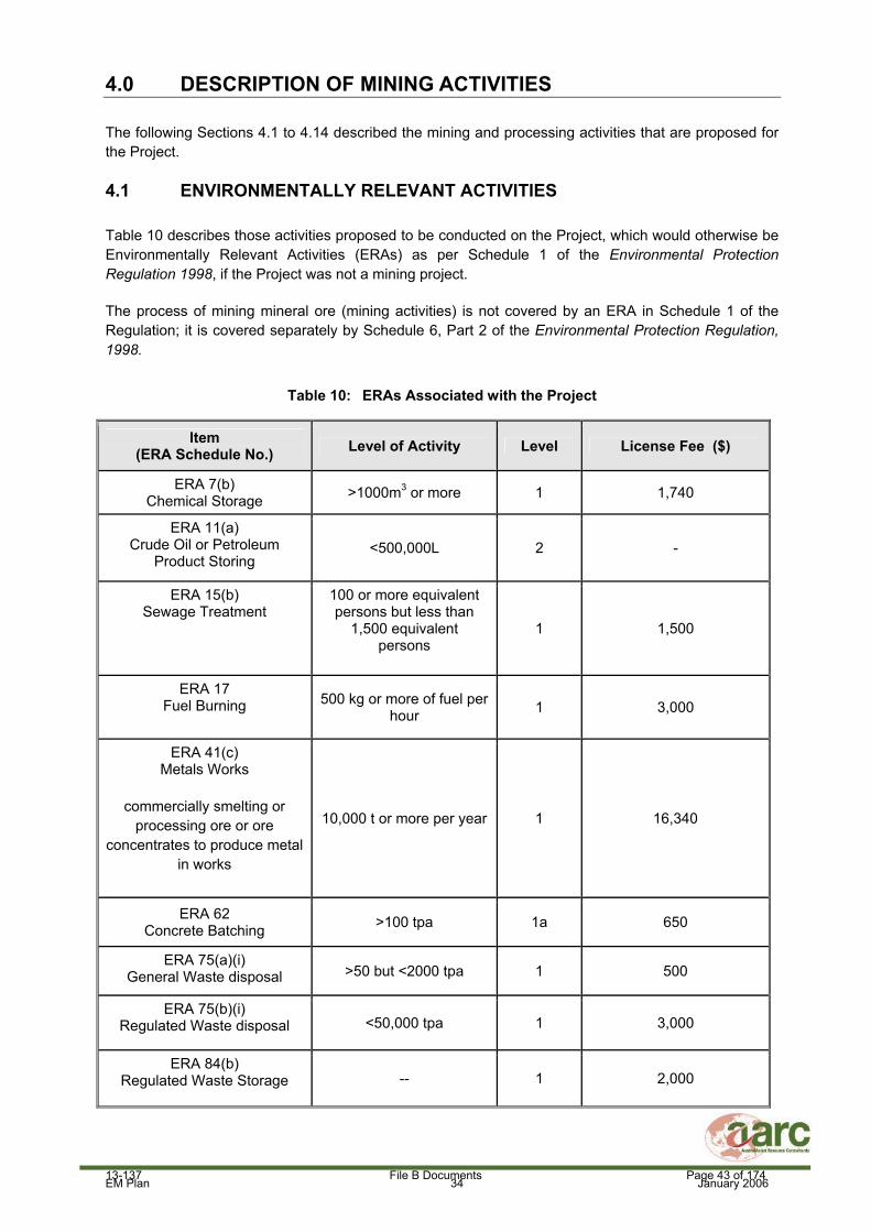
EM Plan 34 January 2006
4.0 DESCRIPTION OF MINING ACTIVITIES
The following Sections 4.1 to 4.14 described the mining and processing activities that are proposed for the Project.
4.1 ENVIRONMENTALLY RELEVANT ACTIVITIES
Table 10 describes those activities proposed to be conducted on the Project, which would otherwise be Environmentally Relevant Activities (ERAs) as per Schedule 1 of the Environmental Protection Regulation 1998, if the Project was not a mining project.
The process of mining mineral ore (mining activities) is not covered by an ERA in Schedule 1 of the Regulation; it is covered separately by Schedule 6, Part 2 of the Environmental Protection Regulation, 1998.
Table 10: ERAs Associated with the Project
Item (ERA Schedule No.) Level of Activity Level License Fee ($)
ERA 7(b) Chemical Storage >1000m3 or more 1 1,740
ERA 11(a) Crude Oil or Petroleum
Product Storing <500,000L 2 -
ERA 15(b) Sewage Treatment
100 or more equivalent persons but less than
1,500 equivalent persons
1 1,500
ERA 17 Fuel Burning 500 kg or more of fuel per
hour 1 3,000
ERA 41(c) Metals Works
commercially smelting or processing ore or ore
concentrates to produce metal in works
10,000 t or more per year 1 16,340
ERA 62 Concrete Batching >100 tpa 1a 650
ERA 75(a)(i) General Waste disposal >50 but <2000 tpa 1 500
ERA 75(b)(i) Regulated Waste disposal <50,000 tpa 1 3,000
ERA 84(b) Regulated Waste Storage -- 1 2,000
13-137 File B Documents Page 43 of 174

EM Plan 35 January 2006
4.2 EXPLORATION
Exploration and drilling activities will continue to be undertaken on the Project area, to determine or prove up further ore resources. Drill pads and sumps will be constructed as necessary, and where possible existing roads and pads will be used.
4.3 VEGETATION REMOVAL AND TOPSOIL STRIPPING
Prior to the development of any open cut pits, waste rock dump or infrastructure, vegetation and topsoil shall be removed from the footprint area and stockpiled. Large vegetation will be pushed first and windrowed along side the area were topsoil will be stockpiled. Smaller vegetation and grasses will be removed with the topsoil and stockpiled in windrows no higher than 2 m. Where necessary, stockpiles will be ripped and seeded to encourage water infiltration and prevent erosion. Topsoil will be respread on surfaces to be rehabilitated as soon as possible to benefit from the viability of the topsoil seed bank.
The approximate amount of land clearing that is required for infrastructure on the Project is shown in Table 11 and Figures 8 and 9.
Table 11: Land Clearance Required on the Project
Disturbance Type Area (ha)
Mount Kelly/Flying Horse Mine Area
Mount Kelly/Flying Horse pit 13.2
Mount Kelly/Flying Horse Waste Rock Dump and Low Grade Stockpile
28
Mount Kelly/Flying Horse Topsoil Stockpile 1.1
Mount Kelly/Flying Horse Sediment Dam 1.3
Mount Kelly/Flying Horse Diversion Drains 1.3
Mount Clarke Mine Area and ROM Pad
Mount Clarke Pit 9.5
Mount Clarke Waste Rock Dump 16.3
Mount Clarke Low Grade Stockpile 5.4
Mount Clarke ROM Storage + Live Rehandle
5.5
Mount Clarke Topsoil Stockpile 4.5
Mount Clarke Pit Area Sediment Dam 0.6
Mount Clarke ROM Area Sediment Dam 0.4
Mount Clarke Diversion/Interception/Sediment Dam Drains
3.2
Processing Plant Area
Process Plant 3.3
ROM Pad and Crushing Station 7.8
Overland Conveyor 1.8
Workshop/Office Access Circuit Area 2.9
13-137 File B Documents Page 44 of 174

EM Plan 36 January 2006
Disturbance Type Area (ha)
Heap Leach Pad – Stage 1 24.2
Heap Leach Pad – Stage 2 19
Process Water Ponds – PLS, ILS and Raffinate
3.4
Stormwater Pond 1 7.2
Stormwater Pond 2 4.2
Stormwater Pond Overflow Channel 0.7
Raw Water Pond 0.6
Process Area Stage 1 Topsoil Stockpile 6.0
Process Area Stage 2 Topsoil Stockpile 3.7
Process Plant Drainage Diversions and Bunding
2.7
Process Plant Sediment Ponds and Overflow Drains
1
Contractor Laydown Area 4.3
Concrete Batch Plant 0.3
Fuel Storage Area 0.3
Bulk Fill Stockpile 2.6
Roads and Other Infrastructure
Site Access Road (on lease) 2.4
Lady Annie Haul Road (on lease) 4.2
Mount Clarke to Mount Kelly ROM Pad Haul Road
5.6
Process Plant/Camp Roads 6.6
Accommodation Camp and Facilities 5
Sewage Effluent Pond 0.2
Exploration 5
Pipeline and Power line Access 1
Domestic Rubbish Dump 0.2
Construction Access
Mount Kelly Process Site Construction Area (net of specific areas)
23.1
Process Plant POM Pad Construction Area (net of specific areas)
8.6
Flying Horse Mine Construction Area (net of specific areas)
12.6
Mount Clarke Mine construction Area (net of specific areas)
10.3
Mount Clarke ROM Pad Construction Area (net of specific areas)
5.3
Total 276.4
13-137 File B Documents Page 45 of 174

EM Plan 37 January 2006
4.4 MINING OF THE DEPOSITS
The Mount Kelly/Flying Horse and Mount Clarke deposits will be mined using conventional open cut, drill, blast and excavation methods, with copper ore being trucked to the Run of Mine (ROM) pad. Benches within the pit will be at 15 m intervals and the overall batter angle of the pit walls will be 45 degrees. The depths of the pits will vary and may be up to 100 m dependant on the nature of the oxide resource and local structural controls.
An average of approximately 1.4 Mt of copper oxide ore (including the Lady Annie deposit) will be extracted for processing by heap leach and SX-EW each year (maximum 1.9 Mtpa). A total of approximately 11 - 12 Mt of copper oxide ore (at an average copper grade of 1.2%) will be extracted from the Project deposits during the life of mine. The current mine life is estimated at eight years. The total resource at the Project may increase with ongoing exploration and this will have the affect of increasing the mine life.
The mining rate is determined by the process plant capacity, which will be designed to produce a maximum of 19,000 tpa of copper cathode.
There will be two open cut pits on the Project, the Mount Clarke pit and Mount Kelly/Flying Horse pit as shown in Figure 9. Land disturbance associated with the final voids will be approximately 23 ha.
Ore from the Mount Kelly/Flying Horse pit and the Mount Clarke pit will be temporarily stockpiled at the Live ROM Rehandle Area before being transported to the Process Plant ROM Pad.
Copper ore mined from the Lady Annie deposit (not included within the Mount Kelly Project area) will be trucked to the proposed processing plant at Mount Kelly. The total maximum mining rate of 1.9 Mtpa includes ore transported from the Lady Annie and Mount Kelly deposits.
Groundwater flows into the pits are not expected to be significant, and therefore water will be collected in a pit sump. Sump water will then be pumped to sediment dams outside the pits for settling and re-use as dust suppression water.
13-137 File B Documents Page 46 of 174
Released

EM Plan 38 January 2006
Figure 8: Conceptual Process Plant Layout
1
2
3
13-137 File B Documents Page 47 of 174

EM Plan 39 January 2006
Figure 9: Conceptual Mining and Infrastructure Layout
13-137 File B Documents Page 48 of 174
Released

EM Plan 40 January 2006
4.5 WASTE ROCK DUMPS
The waste rock dumps will to be constructed via 10m lifts, to an approximate final height of 30 – 40m. The proposed waste rock dumps will be located as shown in Figure 9.
Whilst the waste rock dumps are being constructed, a bund wall will be in place around the toe of the dump to contain water runoff and sediments from the waste dump during storm events. Sediment dams will also be constructed down slope of the waste rock dumps to prevent sedimentation of natural drainage lines. The water quality of any water released from these sediment dams will be monitored by Rising Stage Samplers immediately downstream. Clean water runoff from surrounding catchments will be diverted around the waste rock dumps and allowed to continue in the natural watercourses. It may be necessary to line these channels in places with riprap where expected velocities are greater than 2 m/second.
Once a lift has been completed the outer face of the waste rock dump will be dozed down to an angle of less than 20 degrees. A seven meter wide berm will be left between each lift for drainage and access. Waste rock dumps will be progressively rehabilitated as areas become available.
4.6 PROCESSING ACTIVITIES
4.6.1 Ore Stacking and Heap Leach Pad Design
Ore will be trucked to the proposed processing plant site which will be located on the Mount Kelly West MLA (Figure 8). The ore will be temporarily stockpiled at the Process Plant ROM Pad and crushed. Blending of the Lady Annie and Mount Kelly Project ore will occur as ore is transferred from the ROM Pad to the heap leach pad. Crushing and agglomeration of the ore will occur prior to stacking on the heap leach pads.
The heap leach pads will cover a total area of approximately 43.2 ha (including drainage) and will contain 11 to 12 Mt of ore. The heap leach pads will be constructed in two stages, Stage 1 (24.2 ha) being completed in year 1 of the mine life and Stage 2 (19 ha) in year 2 of the mine life. Two stormwater ponds downstream of the heap leach pads, process water ponds and process plant will provide secondary containment for contaminated stormwater collected during large rainfall events. The two stormwater ponds, one for each heap leach stage, will also be constructed over two years (Figure 8).
The heap leach pads will be constructed in lifts of 6 - 8 m, with up to seven lifts per pad to a total height of 42 meters. The final pad height may vary depending on the characteristics of the material being stacked, but on consolidation the height is expected to be approximately 34m.
All heap leach pads will be constructed with a High Density Polyethylene (HDPE) liner under the pads, drainage controls and associated drain and pond infrastructure. Each heap leach pad will use crushed and screened waste rock as a cushion layer and drain coil to collect leachate from the heap leach pads. Between each lift of the heap leach pads it will be necessary to compact the surface to minimise solution infiltration into material below.
A 1 m high bund wall will be built 5 m from the toe of the heap leach pads to contain any material should a slump occur. This will also act as a solution control bund to contain stormwater runoff from the pads. Clean stormwater will be diverted around the heap leach pads if required.
A leak detection and control system will be developed for the heap leach pads. This will include the installation of a single detection drain down the low side of each 50m wide panel. The bottom end of
13-137 File B Documents Page 49 of 174

EM Plan 41 January 2006
this drain will be extended under the access road and the solution W-drains, to a monitoring stand pipe on the western side of the W-drains.
4.6.2 Copper Leaching Process
Two HDPE pipelines will carry raffinate and intermediate leach liquor containing sulphuric acid to the heap leach pads. From these main pipelines, distribution header pipelines will carry the leach solution onto the top of the leach pads where drippers or wobblers will distribute the leach solution onto the top and sides of the heap leach pads. This solution will percolate through the ore heap and dissolve the copper bearing minerals.
Once the leach liquor (leachate) has passed through the heap, it is collected in drain coil pipes and HDPE lined drains and transferred to the HDPE lined Pregnant Leach Solution (PLS) ponds or the Intermediate Leach Solution (ILS) pond.
From metallurgical test work conducted, the average composition of the leachate in the PLS, ILS and Raffinate ponds is likely to include copper levels of approximately 5,200 mg/L, 1,500 mg/L and 650 mg/L respectively. Average concentrations of other parameters will be similar for all process water ponds and include iron 2,000 mg/L, calcium 600 mg/L, magnesium 9,500 mg/L, aluminium 2,200 mg/L and manganese 700 mg/L. The pH of the solution in the PLS ponds is likely to be approximately pH 1.4.
The composition of the water in the stormwater ponds downstream of the heap leach pad and process water ponds is likely to be significantly diluted as the stormwater ponds will have a capacity greater than 10 times the size of the total capacity of the process water ponds.
4.6.3 Solvent Extraction (SX) and Electro-winning (EW) Process
The liquor from the PLS ponds will be pumped through an SX circuit using mixers and settlers to produce a clean high grade copper electrolyte that is pumped through EW cells where the copper is electroplated onto stainless steel cathodes. After loading, the copper which is stripped from the cathodes is in the form of 1m square sheets of 99.999 % pure LME Grade A copper cathode, and is transported off site to be sold. It is proposed to produce up to 19,000 tpa of copper cathode.
The liquor from which the copper has been removed in the SX circuit (raffinate) will be pumped back to Raffinate ponds were further acid is added (if required). This solution will then be returned for heap leach irrigation. All process solutions are in a closed circuit and are recycled.
4.6.4 Process Water and Stormwater Ponds
It has been determined from the QEPA, Information Sheet – Determining Dams Containing Hazardous Waste that the process water ponds and stormwater ponds will all be High Hazard dams. These ponds will be designed, constructed and operated in line with the QEPA, Code of Environmental Compliance for Environmental Authorities for High Hazard Dams Containing Hazardous Waste.
The process water and stormwater ponds have been assessed against the Site Water Management guideline provided in Technical Guidelines for the Environmental Management of Exploration and Mining in Queensland (1995) to determine their hazard category (Table 1 of guideline) and Design Annual Exceedance Probability (Table 3 of guideline). It has been determined that the ponds will have a High Hazard Category based on the likely water quality in the process water and stormwater ponds.
13-137 File B Documents Page 50 of 174

EM Plan 42 January 2006
There will be three types of process water ponds which include ILS, PLS and Raffinate ponds which will have a combined capacity of 51,100 m3. All ponds will be designed so that in large rainfall events they will overflow to the two stormwater ponds.
Water from the stormwater ponds will be reclaimed to the process water circuit. The water level in Stormwater Pond 1 will equalise with the water level in Stormwater Pond 2. Only Stormwater Pond 1 will be required in the first year of operation as only Stage 1 of the heap leach pad area will be constructed. Stormwater Pond 2 will be staged to be completed in time to contain the catchment of Stage 2 of the heap leach pads in the second year of the Project. The stormwater ponds and process water ponds will be constructed as excavations below ground level and therefore a dam break situation can not occur.
Each of the process ponds and stormwater ponds will be HDPE lined. The process water and stormwater ponds will have an under-liner leak detection system which will consist of leak detection drains under the pond liners, connected to down batter leak detection wells at approximately 50 m centres around the walls of the ponds. Added to this a series of heap leach leak detection bores will be located around the outside of the ponds and processing area to detect any potential seepage to groundwater should the HDPE liner be breached.
The stormwater ponds will be designed to hold a Design Storage Allowance (DSA) of 1:100 year Annual Recurrence Interval (ARI), 2 month wet season (823.9 mm of rainfall) across the catchment area plus process inputs (38,736 m3) at the 1 November every year. For Stage 1 of the heap leach pads the catchment area of Stormwater Pond 1 is 35.5 ha which equates to a runoff volume of 292,484 m3 for the DSA event which is within the 353,860 m3 combined capacity of the process water ponds and Stormwater Pond 1. For Stage 2 of the heap leach pads the total catchment area of both Stormwater Pond 1 and 2 will be 58 ha which equates to a runoff volume of 477,862 m3 for the DSA event which is within the 518,820 m3 combined capacity of process water ponds, Stormwater Pond 1 and 2. The total combined capacity volumes of the process water ponds and stormwater ponds utilises the HDPE lined channels between these ponds as capacity given the inline configuration of the ponds shown in Figure 8.
After rainfall events water from the stormwater ponds will be recycled as process water, thereby ensuring the capacity in the stormwater ponds is always the maximum possible i.e. it is not envisaged that the rainfall from a whole 2 month wet season would be allowed to accumulate in the stormwater ponds. Evaporation from the surface of the stormwater ponds (which hasn’t been taken into account in the design storage allowance) will further reduce the amount of water in these ponds after rainfall events.
The stormwater ponds will each have an overflow spillway which is designed to pass the peak flow from a 1:1,000 year ARI storm event. Water from these spillways, in the unlikely event of an overflow, would flow through a channel to the upper reaches of Saga Creek as shown on Figure 8.
The Mandatory Reporting Levels to be marked on each stormwater pond below the spillway, will equal the volume left in the pond to hold a 1:100 year ARI, 72 hour event (339.12mm) over the catchment area. For Stormwater Pond 1 in Stage 1, this Mandatory Reporting Level will be marked at 1.7 m below the spillway and is equal to a volume of 120, 400 m3 left in the pond. For Stormwater Ponds 1 and 2 in Stage 2 of the Project this Mandatory Reporting Level will be marked at 1.9 m below the spillway and is equal to a volume of 196, 700 m3 left in the ponds.
Should the water level in the stormwater ponds reach the mandatory reporting level then the Administrating Authority (QEPA) will be contacted immediately. The QEPA may at this point issue instructions to CopperCo Limited regarding contingency measures that need to be taken should the water level in the ponds exceed the level below the spillway of a 1:10 year ARI, 24 hour event
13-137 File B Documents Page 51 of 174
Released

EM Plan 43 January 2006
(150mm of rainfall across the catchment) which is equal to 0.65 m below the spillway for Stage 1 and 0.75 m for Stage 2.
The extent of the impacts of overtopping the ponds on ephemeral surface water flows and quality downstream would be dependant on a number of variables including the quality, flow and volume of the discharged water and the flow, volume and quality of natural receiving waters. The size of a rainfall event that would be required to overtop the ponds (greater than 1:100 year ARI, 72 hour event) would ensure that the discharged water would have a substantial dilution factor in any receiving waters.
All practical alternatives to prevent the stormwater ponds overtopping, or to improve water quality of the discharged water, would be implemented should an overtopping event appear imminent.
CopperCo Limited proposes the following contingency measures if the Mandatory Reporting Level is reached in the stormwater ponds:
1. A water sample will be taken from each process water and stormwater pond and sent to a NATA registered laboratory to determine water quality.
2. Field measurements will be conducted in each pond using a portable pH and Electrical Conductivity (EC) meter on a weekly basis should rainfall continue.
3. No additional water will be added to the process water system under any circumstance and water from the stormwater ponds will recycled to the process plant.
4. Weekly recordings of the water level in the ponds below the spillway crest and any rainfall.
Should the water level in the ponds reach the level below the spillway crest of a 1:10 year ARI, 24 hour event (150mm of rainfall across the catchment area) then the following strategies will be implemented:
1. The QEPA will be notified immediately.
2. A water sample will be taken from each process water and stormwater pond to and sent to a NATA registered laboratory to determine water quality.
3. Field measurements will be conducted in each pond using a portable pH and (EC) meter on a daily basis.
4. Process water will continue to be circulated through the heap leach pads to prevent drain down of the heaps.
5. Contingency measures will be developed to prevent an overflow in conjunction with the QEPA.
Should an overflow of the stormwater ponds occur, the time that the discharge starts and finishes will be recorded along with approximate depths at regular intervals over the spillway. Water samples from the discharge will be taken at both the stormwater pond and downstream at the lease boundary at regular intervals to determine if environmental harm has occurred.
13-137 File B Documents Page 52 of 174
Released

EM Plan 44 January 2006
4.7 RAW WATER POND
A raw water pond will be constructed in a Turkeys Nest design at the site of the processing plant to store water from the raw water pipeline. Water from this pond will be used to top up water in the process water circuit. The Raw Water Pond will be lined with HDPE with dimensions of 55 m x 55 m x 6 m deep and have a capacity of 8,500m3. The raw water pond will contain fresh, good quality water from either the borefield or Greenstone Creek Dam (Waggaboonya Dam).
4.8 WATER REQUIREMENTS
An estimated 20 L/s water supply is required for the construction phase of the project based on a construction demand of 1500 m3/day (17.5 L/s), plus a potable water allowance for personnel being accommodated in camps.
The preferred source of this water is the Greenstone Creek Dam (Waggaboonya Dam), however, given that the water supply pipeline from Waggaboonya Dam to the Project site is unlikely to be completed in time for construction, additional near-mine water sources are required.
Analysis has indicated that it is more feasible to gain adequate water supply from several local sources rather than from a single source. These sources potentially include:
The Mount Kelly area existing bore (Mount Kelly Camp Bore);
The Flying Pig Bore at Lady Annie;
The proposed Lady Annie Dewatering Bores (yet to be constructed);
Supply from the existing Lady Annie East (LAE) Borefield; and,
Potential supply from the Buckley River area south of Mount Kelly.
Prior to the establishment of new bores or use of existing bores, all the necessary permits will be obtained from the relevant authorities. Environmental impacts will be assessed as part of the permitting process and appropriate environmental controls will be implemented in accordance with the permits.
The water supply requirements for the processing, mining and potable water supply have been assessed to be a maximum of 42 litres/second. This equates to an annual water requirement of 1.3 million m3.
There are two options for the water supply for the Project. The preferred strategy is to obtain water from the Greenstone Creek Dam (Waggaboonya Dam) located at Mount Gordon Mine via a pipeline to the Project. This dam is already constructed with an approved water supply allocation which may be sufficient for both the needs of the Mount Kelly Project and the Mount Gordon Mine. An assessment of this water supply option is currently being undertaken to determine allocations and feasibility. If required, further licences or permits will be sought from DNRM. Waggaboonya Dam lies approximately 35 km north-east of the proposed Mount Kelly process plant site and was built in 1969 on Greenstone Creek as a water supply for the pre-existing Gunpowder Township. The dam has a maximum storage of 14,000 ML. Currently, Waggaboonya Dam is utilised by Birla Mount Gordon for mine process water and camp water supply purposes. Two water extraction licences for this storage are held by Birla Mount Gordon, which permit a combined total extraction of 64 L/s (2,020 ML/yr).
13-137 File B Documents Page 53 of 174

EM Plan 45 January 2006
The second water supply option is to obtain water by developing the Thorntonia Borefield which is located 65 km north of the Mount Kelly Project. Water licences and permits will be applied for if this water supply option is pursued.
4.9 POWER SUPPLY
The power supply for the Project has been estimated at 7.25 MW and is likely to be provided by a spur line from the 11kV power line to the Mount Gordon Mine. A small backup diesel generator will be required to supply a trickle current to the processing plant.
A generator will be required at the accommodation camp to provide power.
4.10 CONCRETE BATCHING
A concrete batching plant will be established to supply concrete during the construction phase of the project and to a lesser extent during operations. The plant will be located in close proximity to the Processing Plant and will include small storage areas for raw materials and cement.
4.11 ACCOMMODATION CAMP
A temporary accommodation camp to house approximately 140 people will be constructed on the Mount Kelly Extended MLA to the south of the Swagman deposit. Figure 10 below shows the personnel requirements for the Project.
Personnel will operate on a fly in fly out roster with the Mount Isa airport utilised as the main hub for personnel travelling to and from the site.
Figure 10: Organisational Chart
Admin – 13 Mining – 74 Process – 50 TOTAL = 137
13-137 File B Documents Page 54 of 174

EM Plan 46 January 2006
4.12 SEWAGE TREATMENT
The offices and workshops at the Mount Kelly processing plant will be serviced by septic sewage systems. These systems will be serviced and pumped out by a licensed contractor on a regular basis with the resulting sludge being disposed of to a licensed facility.
There will be two sewage treatment plants to support the Project. The larger of these will be a 148 person plant to cater for the permanent camp. The other unit will be an 80 person plant that will cover the additional people on site for construction. This smaller plant will be removed from site after the construction peak is over.
The capacity of the 148 person plant is 38,000 L/day. This capacity has been determined by allowing 250 L/day/person for 148 people and then rounding up. The capacity of the 80 person plant is 20,000 L/day. This capacity has been determined by allowing 250 L/day/person per person for 80 people.
The sewage treatment process is illustrated in Figure 11.
13-137 File B Documents Page 55 of 174

EM Plan 47 January 2006
Figure 11: Treatment Process for Sewage Treatment Plant for the Accommodation Camp
13-137 File B Documents Page 56 of 174

EM Plan 48 January 2006
The process consists of raw sewage flowing to the raw sewage pump well, which has a capacity of 3,900L. The raw sewage is pumped to the Treatment Tank Container (TTC) via the raw sewage main. Inside the TTC are two submersible aerators, two decant pumps and three float switches. The plant operates over three phases; aeration, settling and decanting. The aeration period typically lasts approximately 60 minutes and can be increased or decreased according to plant load.
The settling period follows aeration to settle out solids and also lasts for approximately 60 minutes. The plant will continue to pass through these two phases until the midlevel float switch in the TTC is reached. At this point the plant will immediately switch to a Settle period if it was in an Aeration period. The plant will then settle for 60 minutes, which allows time for the activated sludge to settle in the TTC.
Upon completion of the settling period both decant pumps are activated. The clear effluent is pumped from the TTC via the transfer pipe to the Treated Effluent Tank located in the second container. This tank acts as an equalisation tank. When the level in the TTC falls to the lowest float level switch, the Decant pumps are switched off and the cycle recommences.
Final disinfection occurs when the treated effluent passes through the tablet chlorinator upon exit from the Treated Effluent Tank, achieving chlorination of effluent with a residual of 2ppm.
A properly maintained plant produces treated effluent with:
Biological Oxygen Demand < 20 mg/l
Suspended Solids < 30 mg/l
Faecal Coliforms < 10 in 100ml.
Any grits, scums or sludges from the sewage treatment plant will be removed and disposed of by a licensed contractor to an appropriately licensed facility.
The water from the sewage treatment plant will not be used for effluent irrigation to naturally vegetated areas. The water treated from the sewage treatment plant will piped to a nearby lined, waste water pond prior to being used for dust suppression on roads on the Project. The water will be pumped out of the waste water pond via a stand pipe into water trucks and then sprinkled on to the roads and other processing areas requiring dust suppression. Given the proposed water quality of the final effluent it unlikely that disposing of this effluent by road watering for dust suppression would lead to contamination to surface waters, groundwater or land.
The waste water pond will not receive any surface water run off from surrounding areas and as such flooding of the waste water pond will be unlikely. Sufficient capacity will be provided in the waste water pond to contain treated sewage water plus rainfall falling directly in the pond during times when dust suppressions is not required (i.e. during rainfall events).
Figure 8 shows the site of the proposed sewage treatment plant area and waste water pond. There are no nearby neighbours, sensitive areas or waters that will be impacted by the sewage treatment plant or waste water pond.
13-137 File B Documents Page 57 of 174

EM Plan 49 January 2006
The plant is a closed system and therefore stormwater will not be collected within the system or contaminated in normal operating conditions. Clean stormwater collected in the bunded area surrounding the sewage treatment plant would be pumped into the waste water pond to be used for dust suppression.
The sewage treatment plant will be surrounded by earthern bunds. The bunded areas will be sized such that they will hold the capacity of the tanks along with highest recorded monthly rainfall for the area. In the event of heavy rain, and if there is no contamination, the rain water in the bund would be pumped to the waste water pond near the plant and used for dust suppression at a later date. In the event of a plant overflow the waste water would be pumped out of the bunded area by a certified waste disposal contractor and disposed of off site to an appropriately licensed facility.
Flood potential of the treatment plant and waste water pond is considered to be minimal as they are located on a flat plateau, adjacent to the accommodation camp with minimal catchment upstream.
CopperCo Limited will be responsible for the operation and maintenance of the sewerage treatment plant and waste water pond. The manufacturer also provides a range of management options, including remote operation and on-site training of staff.
In addition, the site induction for new employees will cover site environmental issues, including any issues of relevance to the sewage treatment plant. On-going issues will be addressed by site memos.
Contingency plans for emergencies/environmental incidents associated with the sewage treatment plant will include the following:
Equipment failure - the units will be equipped with duty and standby pumps.
Power Outage - The camp will have a generator that will provide power to the plant in the event of a mains power failure.
Process upset - trained personnel on site.
4.13 GENERAL INFRASTRUCTURE
General infrastructure that will be required on the Project that has not been discussed previously will include:
Workshops and administration buildings;
Fuel Storage - 2 x 70,000 litres tanks;
Sulphuric acid and extractant storage;
Borrow pits for road construction;
Contractors laydown area and boneyard; and
General rubbish disposal site.
All hydrocarbons will be stored and handled as per the requirements of section 5.8 of AS 1940 - Storage and Handling of Flammable and Combustible Liquids of 2004.The on-site storage of corrosive
13-137 File B Documents Page 58 of 174

EM Plan 50 January 2006
liquids will be in accordance with section 5.7 of AS 3780 - Storage and Handling of Corrosive Substances 1994.
The rubbish disposal site will consist of two long trenches one for industrial type rubbish and the other for domestic putrescible type rubbish from the offices and camp. Each trench will be covered on a regular basis (at least weekly) to prevent the dispersal of wind borne rubbish, control scavenging by feral animals and deter insect breeding.
A laydown and recycling area will be developed to aid in the separation of re-useable and recyclable materials. This area will be used for the storage of wastes such as scrap metal, tyres and vehicle batteries prior to collection from site by a licensed contractor for disposal or recycling to a licensed facility. A Waste Management Plan for the Project will be developed and reported in the Plan of Operations to aid in the management and recycling of wastes from the site (Milestone 6).
4.14 TRANSPORT
Transport of copper cathode product, supplies and personnel to and from the Project will be via existing public roads between Mount Isa and the Project which includes McNamara’s Road and the Barkley Highway. CopperCo Limited plan to upgrade McNamara’s Road in consultation with the relevant government authorities to allow better access to the Project site.
It is anticipated that the following number of transport movements will be required for Project on a weekly basis:
Acid - 10 triple road trains; Copper - ( back load on acid trucks ); Diesel - 2 triples; Freight - 1 semi trailer; Light vehicles - 7; Personnel - mini bus 2 round trips; and Visitors - 35 light vehicles per week.
13-137 File B Documents Page 59 of 174
Released

EM Plan 51 January 2006
5.0 REHABILITATION
5.1 EXPLORATION
Exploration disturbances will be rehabilitated as per the following six steps:
Capping the drill hole;
A drying out period to allow water to evaporate from the drilling muds in the sumps;
Backfilling of drilling sumps;
Scarifying the surface; and
Should natural regeneration not be successful after the first year, seed from species native to the area will be sown before the following wet season to enhance revegetation.
5.2 HEAP LEACH PADS
Once commercially viable quantities of marketable copper can no longer be leached from a heap leach pads, the heap will be rehabilitated.
The heap leach pad will be reshaped to blend with the surrounding topography at a grade of less than 1:3 or 33%. Depending on the results of rehabilitation trials the resultant landform may be covered with approximately 50 cm of coarse waste rock material. Topsoil (to a thickness of at least 100 mm, if available) will then be spread over the surface of the rock and lightly ripped, fertilised and seeded with local shallow rooting species.
Drainage from the rehabilitated heap will drain to a channel around the perimeter of the heap and then to the process water ponds. Any water discharged from the rehabilitated heap leach impoundment will be monitored for water quality until the rehabilitated landform has been deemed to have met completion criteria.
5.3 WASTE ROCK DUMPS
Waste rock dumps will be rehabilitated by leaving a berm of at least 5 m between each lift once the dump faces have been dozed down to act as a water control structure to prevent erosion of the lower waste dump face.
The final slope of the waste rock dump face once dozed down for rehabilitation will be between the angle of repose and 20 degrees depending on the competency of the rock material. The berm between the two lifts of the dump will be graded to slope back towards the dump to act as a water control structure for any stormwater flowing off the lift above. The top of the waste rock dump will graded towards the centre and a drain or bund installed back from the edge to prevent any overtopping of water from the top of the dump over the face of the dump.
The slopes and top of the waste rock dumps will be topsoiled were possible and deep ripped to bind in the material. Native local grass and tree species and an appropriate fertiliser, if required, will be directly seeded onto the topsoiled dump.
13-137 File B Documents Page 60 of 174

EM Plan 52 January 2006
5.4 FINAL VOIDS
Final voids will be left in a safe condition by constructing a safety bund wall around each void from competent rock and/or fencing, depending on the terrain, to limit human and livestock/animal access. The safety bund wall will be constructed as described in Technical Guidelines for the Environmental Management of Exploration and Mining in Queensland. This guideline states that the bund wall should be of a minimum height of 2 m, with a minimum base width of 4 m and be located at least 10 m beyond the area potentially affected by any instability of the pit edge.
Where water quality within the void is suitable for stock drinking water, a safe access to the water shall be provided for stock, or the water will be pumped to a stock watering point. Consultation with the land holder will be undertaken to determine the best means of pumping or access. Where water in voids is not suitable for stock drinking water, then the voids will be bunded or fenced to prevent stock access.
5.5 PLANT AND INFRASTRUCTURE
All process plants and associated buildings and equipment will be dismantled and removed upon the cessation of mining operations, or on agreement left for the land holder.
5.6 ACCESS ROADS
Access roads required for grazing activities will not be rehabilitated. This will be confirmed by written agreement with the pastoralist. Roads that can be rehabilitated will be deep ripped and if necessary seeded with a mix of native grass and tree species.
5.7 REVEGETATION METHODS
Compacted areas will be topsoiled (if topsoil is available), ripped to a depth of 500 mm and fertilised with a nitrogen and phosphate based fertiliser, if required. The area will be seeded with appropriate plant species, which occur naturally in the local area. Ripping the soil surface will slow down surface water flows and minimise the potential for erosion.
13-137 File B Documents Page 61 of 174

EM Plan 53 January 2006
6.0 ENVIRONMENTAL VALUES, IMPACTS, CONTROL STRATEGIES AND PROPOSED EA CONDITIONS
In accordance with the QEPA guideline for the preparation of an EM Plan for non-standard mining Projects (QEPA, 2003), this section provides a description of environmental values likely to be affected by the Project. For each environmental value identified an assessment of the beneficial and adverse impacts from the Project to that value will be described. Environmental objectives and control strategies will be proposed for the protection of each environmental value and EA conditions containing measurable standards and Indicators developed. In doing so, the following is discussed where relevant:
The magnitude or relative size of the impact in relation to the environmental value being discussed;
The severity of any adverse effect or scale of any beneficial outcome;
The duration of the effect; and
An indication of the level of uncertainty and any assumptions used to address the uncertainty in any of the data or proposed commitments to protect the environmental values.
The following is a list of definitions for terms that will be used in this section:
Environmental Values: Environmental values are those qualities or physical characteristics of the environment that are conducive to ecological health, public amenity, or safety.
Environmental Protection Objectives: These describe the key elements of the environment and the level to which they should be protected in order to prevent impacts on the environmental values.
Control Strategies: These set out the technological, management and other approaches to be taken in meeting the environmental protection objectives and achieving the proposed standards.
Measurable Indicators: These are the activities or target areas through which the level of achievement of the environmental protection objective can be determined.
Standards: These are defined numerical standards or clear actions for each of the indicators by which adequate levels of achievement of the environmental protection objectives and protection of the environmental values can be determined.
6.1 GENERAL EA CONDITIONS
Financial Assurance (A1-1) Provide a financial assurance in the amount and form required by the administering authority prior to
the commencement of activities proposed under this environmental authority.
NOTE: The calculation of financial assurance for condition (A1-1) must be in accordance with Guideline 17 and may include a performance discount. The amount is defined as the maximum total rehabilitation cost for complete rehabilitation of all disturbed areas, which may vary on an annual basis due to progressive rehabilitation. The amount required for the financial assurance must be the highest Total Rehabilitation Cost calculated for any year of the Plan of Operations and calculated using the formula: (Financial Assurance = Highest Total Annual Rehabilitation Cost x Percentage Required).
13-137 File B Documents Page 62 of 174

EM Plan 54 January 2006
(A1-2) The financial assurance is to remain in force until the administering authority is satisfied that no claim on the assurance is likely.
NOTE: Where progressive rehabilitation is completed and acceptable to the administering authority, progressive reductions to the amount of financial assurance will be applicable where rehabilitation has been completed in accordance with the acceptance criteria defined within this environmental authority.
Maintenance of Measures, Plant and Equipment (A2-1) The environmental authority holder must ensure:
that all measures, plant and equipment necessary to ensure compliance with the conditions of this environmental authority are installed;
that such measures, plant and equipment are maintained in a proper condition; and
that such measures, plant and equipment are operated in a proper manner.
Monitoring
(A3-1) Record, compile and keep for a minimum of five years all monitoring results required by this environmental authority and make available for inspection all or any of these records upon request by the administering authority.
(A3-2) Where monitoring is a requirement of this environmental authority, ensure that a competent person(s) conducts all monitoring.
Storage and Handling of Flammable, Combustible and Corrosive Liquids (A4-1) Spillage of all flammable and combustible liquids must be contained within an on-site containment
system and controlled in a manner that prevents environmental harm (other than trivial harm) and maintained in accordance with Section 5.8 of AS 1940 - Storage and Handling of Flammable and Combustible Liquids of 2004.
(A4-2) The on-site storage of corrosive liquids must be in accordance with Section 5.7 of AS 3780 - Storage and Handling of Corrosive Substances 1994.
Definitions (A5-1) Words and phrases used throughout this environmental authority are defined in Schedule H –
Definitions. Where a definition for a term used in this environmental authority is sought and the term is not defined within this environmental authority, the definitions in the Environmental Protection Act 1994, its Regulations and Environmental Protection Policies must be used.
13-137 File B Documents Page 63 of 174

EM Plan 55 January 2006
6.2 AIR
6.2.1 Environmental Value
Air quality typical of a rural environment compromised infrequently by diffuse dust from surrounding grazing and mineral exploration activities.
6.2.2 Description of Environmental Value
The nearest non Project related sensitive place that could be potentially impacted by the Project is approximately 30 km away at the Mount Gordon mine camp. Due to the distance of the sensitive receiver from the operations, the limited air emissions from the mining and processing activities and the control strategies to be employed, it is unlikely that the operations would have any significant effect on the air quality at this receiver.
6.2.3 Assessment of Impacts on the Environmental Values
The potential air quality impacts from the activities at the Project may include:
Air emissions from diesel generators;
Air emissions from company vehicles and heavy equipment;
Dust from vehicle movements on unsealed roads;
Dust from clearing activities;
Dust generated from disturbed areas on the leases such as waste rock dumps;
Dust from blasting and mining of open cut pits; and
Dust from materials handling and crushing on the leases.
All potential air contaminates are from fugitive sources and therefore there will be no point source releases on the Project.
The mining and processing activities on the Project will not produce any significant odour. The only activities to be conducted that could potentially cause odour would be the disposal of putrescible wastes and the sewage treatment facilities. Given the distance of the nearest residence from these activities, it is highly unlikely that odour nuisance will occur.
6.2.4 Proposed Environmental Protection Objective
To ensure that the local ambient air quality is maintained and that emissions from the Project do not impact on sensitive places.
13-137 File B Documents Page 64 of 174
Released

EM Plan 56 January 2006
6.2.5 Control Strategies
Control strategies will include:
A complaints register will be maintained to record and investigate all bona fide complaints;
Ongoing rehabilitation and revegetation of the site;
Minimisation of disturbed areas;
Limited vehicle speed within infrastructure areas and mine access roads;
Gaseous emissions from the diesel generators, vehicles and earthmoving equipment will be minimised by ensuring that all equipment is regularly serviced and well maintained so that fuel combustion occurs at optimal efficiency;
The heap leach pads will be kept damp by the irrigation system and therefore dust is not likely to be generated from this area;
Disturbed areas on the lease will be rehabilitated progressively to prevent dust generation;
Stockpiles and internal unsealed roads will be watered to prevent the generation of excessive dust; and
Putrescible waste will be covered on a regular basis (at least weekly) to reduce odour.
6.2.6 Proposed EA Conditions using Measurable Indicators and Standards
Dust Nuisance (B1-1) Subject to Conditions (B1-2) and (B1-3) the release of dust or particulate matter or both resulting from
the mining activity must not cause an environmental nuisance at any sensitive or commercial place.
(B1-2) When requested by the administering authority, dust and particulate monitoring must be undertaken within a reasonable and practicable timeframe nominated by the administering authority to investigate any complaint (which is neither frivolous nor vexatious nor based on mistaken belief in the opinion of the authorised officer) of environmental nuisance at any sensitive or commercial place, and the results must be notified within 14 days to the administering authority following completion of monitoring.
(B1-3) If the environmental authority holder can provide evidence through monitoring that the following limits are not being exceeded then the holder is not in breach of (B1-1):
a) Dust deposition of 120 milligrams per square metre per day, averaged over one month, when monitored in accordance with AS 3580.10.1 Methods for sampling and analysis of ambient air - Determination of particulates - Deposited matter - Gravimetric method of 1991.
(B1-4) If monitoring indicates exceedence of the relevant limits in Condition (B1-3), then the environmental authority holder must:
a) address the complaint including the use of appropriate dispute resolution if required; or
b) immediately implement dust abatement measures so that emissions of dust from the activity do not result in further environmental nuisance.
13-137 File B Documents Page 65 of 174
Released

EM Plan 57 January 2006
Odour Nuisance (B2-1) Subject to condition (B2-2), the release of noxious or offensive odour(s) or any other noxious or
offensive airborne contaminant(s) resulting from the mining activity must not cause an environmental nuisance at any sensitive or commercial place.
(B2-2) When requested by the administering authority, odour monitoring must be undertaken within a reasonable and practicable timeframe nominated by the administering authority to investigate any complaint (which is neither frivolous nor vexatious nor based on mistaken belief in the opinion of the authorised officer) of environmental nuisance at any sensitive or commercial place, and the results must be notified within 14 days to the administering authority following completion of monitoring.
(B2-3) If monitoring indicates Condition (B2-1) is not being met then the environmental authority holder must:
a) address the complaint including the use of appropriate dispute resolution if required; or
b) immediately implement odour abatement measures so that emissions of odour from the activity do not result in further environmental nuisance.
13-137 File B Documents Page 66 of 174

EM Plan 58 January 2006
6.3 WATER MANAGEMENT
6.3.1 Environmental Value
Ephemeral surface water in local watercourses is potentially a source of water for stock and is of environmental value to the surrounding grazing industry, the local community and native flora and fauna.
The groundwater quality is of environmental value to the local grazing industry and therefore protection of existing groundwater quality must be maintained to ensure ongoing and sustainable use of this resource.
6.3.2 Description of Environmental Value
Stream sediments, surface water and groundwater on the Project are described in Sections 3.5, 3.6 and 3.7 respectively, of this EM Plan.
6.3.3 Assessment of Impacts on the Environmental Values
Surface Water The potential surface water quality impacts from activities on the Project include surface water runoff containing elevated concentrations of sediment, Total Dissolved Solids (TDS), sulphate, metals and low pH water from areas such as:
Stockpiles of waste rock and ore;
Heap leach pads, process water ponds and stormwater ponds;
Workshops, hydrocarbon and chemical storage areas; and
Sewage treatment plant.
Stream diversions around mine infrastructure and workings may also have the potential to effect water quality and flows downstream.
Groundwater The potential groundwater water quality impacts from the Project activities could include infiltration of process water, mine water, sewage water or leachate to the groundwater containing elevated concentrations of TDS, sulphate, metals and low pH water from areas such as:
Voids containing pit water;
Waste rock dumps and stockpiles;
Heap leach pads, process water ponds and stormwater ponds; and
Septic systems or the sewage treatment plant.
13-137 File B Documents Page 67 of 174

EM Plan 59 January 2006
6.3.4 Proposed Environmental Protection Objective
To prevent degradation of water quality in the ephemeral creeks downstream of the Project and the local groundwater aquifer.
6.3.5 Control Strategies
Control strategies will include:
Clean stormwater runoff will be separated from contaminated stormwater by the use of diversion bunds and drains around the processing activities, mine workings and waste rock dumps. Measures will be employed to not significantly increase the volume or flow velocities of waters being diverted;
The heap leach pad, process water ponds, stormwater ponds and channels will be completely contained with a 1.5 mm thick HDPE liner, 100 % weld tested;
The process water and stormwater ponds will be designed as described in Section 4.6.4 of this EM Plan to provide for contingency measures to prevent overtopping in large rainfall events or if overtopping does occur prevent environmental harm downstream;
All spills of fuels or chemicals will be cleaned up as soon as possible. Contaminated areas will be remediated in accordance with relevant guidelines and standards;
A spill kit containing absorbent material for fuels and chemicals contained on the leases will be maintained;
Fuel and chemical storage facilities will be contained and operated as per the relevant Australian Standard.
Groundwater monitoring will be conducted on the Project to determine background water quality and any change in quality that may be due to the operations. The total groundwater monitoring network in the vicinity of the plant and heap leach area will (assuming that groundwater is a subdued reflection of surface topography with a westerly flowing surface drainage) comprise eight (8) downstream monitoring bores, and six (6) upstream or heap leach peripheral bores;
The heap leach pads, process water ponds and stormwater ponds will include a leak detection and control system. For ponds, this will consist of leak detection drains being installed under pond liners and connected to down batter to the leak detection wells installed at approximately 50 m centres around the walls of the ponds. For the heap leach pad, a single detection drain will be installed down the low side of each 50m wide panel. The bottom end of this drain will be extended under the access road and the solution W-drains, to a monitoring stand pipe on the western side of the W-drains. The reasons for any increases in contaminants above the designated standards will be investigated and corrective actions implemented if necessary. The results of the investigation and mitigation strategies, if necessary, will be reported to the QEPA.
Each sediment dam will have a filtered pipe as a primary outlet from the pond for gradual release of collected water over a 48 hour period. The outlet pipe will run through a wet well manhole beside the downstream channel where a Rising Stream Sampler will be mounted.
13-137 File B Documents Page 68 of 174

EM Plan 60 January 2006
Each pond will be provided with an overflow spillway to cater for storm events greater than the 10 year design storage event.
Downstream water quality will be conducted in all streams that could be potentially impacted by mine activities on a regular basis. Upstream water quality monitoring will also occur to provide further baseline data for the Project. The reasons for any increases in contaminants above the designated standards will be investigated and corrective actions implemented if necessary. The results of the investigation and mitigation strategies, if necessary, will be reported to the QEPA.
Septic systems and treatments plants will be maintained on a regular basis, including pumping out when necessary, to maintain optimum efficiency;
Water monitoring will be conducted annually to determine the water quality in any pit voids;
Where water quality in voids is not suitable for stock drinking water, access by stock to this water will be prevented;
Any land disturbance within streams beds and adjacent to their bank will be kept to a minimum and stabilised immediately on completion of works;
All major land disturbances on the Project that may have the potential to produce soil erosion or excessive sediment during storm events (i.e. waste rock dumps) will be drained via sediment traps to drop out suspended sediment prior to discharge of stormwater to natural stream systems;
Progressive rehabilitation of land disturbances during the Project life will be undertaken where possible to reduce the potential for excessive sediment loads from disturbed land;
An annual stream sediment and morphology monitoring program will be conducted for all streams downstream of any mining or infrastructure related disturbances once Project construction has commenced. The monitoring program will include an adequate number of upstream background sites so that natural variations in stream sediment quality and morphology are also monitored;
Should the stream sediment monitoring program detect metal concentrations downstream of mining activities higher than the low or high trigger values, then an investigation into the likely causes will be initiated. The results of the investigation and mitigation strategies, if necessary, will be reported to the QEPA; and
Waste rock dumps and the ROM pad will be drained via sediment traps to remove suspended materials prior to discharge.
6.3.6 Proposed EA Conditions using Measurable Indicators and Standards
Release to Waters (C1-1) Receiving waters affected by the release of process water or storm water contaminated by the mining
activities or both must be monitored at the locations and frequencies defined in Table 12 and Figure 12 and the results of the test sites comply with the contaminant limits defined in Table 14.
13-137 File B Documents Page 69 of 174

EM Plan 61 January 2006
Table 12: Schedule C - Receiving Water Monitoring Locations and Frequency
Monitoring point Easting (AMG 84,
Zone 54) Northing (AMG 84,
Zone 54) Monitoring frequency
MKUS 1 – reference site* 305625 7797450 Each flow event.MKUS 2 – reference site* TBD TBD Each flow event.MKDS 1 – test site 301160 7800135 Each flow event.MKDS 2 – test site 306366 7798356 Each flow event.MKDS 3 – test site 306370 7798363 Each flow event.MKDS 4 – test site 301300 7797255 Each flow event.NOTE: This does not apply to dams containing hazardous waste *Reference sites must: a) be from the same biogeographic and climatic region; b) have similar geology, soil types and topography; c) contain a range if habitats similar to those at the test sites; d) be of a similar follow regime; and e) not be so close to the test sites that any disturbances at the test site also results in a change at the reference site. TBD- to be determined and provided to the QEPA prior to commencement of mining.
Figure 12: Surface Water and Stream Sediment Monitoring Locations
13-137 File B Documents Page 70 of 174

EM Plan 62 January 2006
(C1-2) Subject to Condition (C1-1), if the receiving water contaminant trigger levels defined in Table 13 are exceeded at the test sites then the environmental authority holder must complete an investigation into the potential for environmental harm and notify the administering authority within 3 months of receiving the analysis results.
Table 13: Schedule C - Receiving Water Contaminant Trigger Levels
Parameter Units Level Trigger Type
pH pH units 6-81 Range EC μS/cm 2501 Maximum Aluminium mg/l 2.52 Maximum Arsenic mg/l 0.252 Maximum Boron mg/l 0.373 Maximum Cadmium mg/l 0.0052 Maximum Chromium mg/l 0.52 Maximum Cobalt mg/l 0.52 Maximum Copper mg/l 0.52 Maximum Fluoride mg/l 12 Maximum Lead mg/l 0.052 Maximum Manganese mg/l 1.93 Maximum Mercury mg/l 0.0012 Maximum Molybdenum mg/l 0.0752 Maximum Nickel mg/l 0.52 Maximum Sulphate mg/l 5002 Maximum Selenium mg/l 0.012 Maximum Zinc mg/l 102 Maximum 1Contaminant trigger limits are based on Table 3.3.4 and 3.3.5 of Aquatic Ecosystems ANZECC (2000).
2Contaminant trigger limits are based on 50% of the contaminant limits defined in the ANZECC (2000) Livestock Drinking Water and are to be analysed as Total Metals (unfiltered).
3Contaminant trigger limits based on Table 3.4.1 of Aquatic Ecosystems ANZECC (2000) and are to be analysed as Dissolved Metal (filtered).
13-137 File B Documents Page 71 of 174

EM Plan 63 January 2006
Table 14: Schedule C - Receiving Water Contaminant Limits
Parameter Units Limit Trigger Type
pH pH units 6 - 9 Range TDS mg/l 4,000 Maximum Aluminium mg/l 5 Maximum Arsenic mg/l 0.5 Maximum Boron mg/l 5 Maximum Cadmium mg/l 0.01 Maximum Chromium mg/l 1 Maximum Cobalt mg/l 1 Maximum Copper mg/l 1 Maximum Fluoride mg/l 2 Maximum Lead mg/l 0.1 Maximum Mercury mg/l 0.002 Maximum Molybdenum mg/l 0.15 Maximum Nickel mg/l 1 Maximum Sulphate mg/l 1,000 Maximum Selenium mg/l 0.02 Maximum Zinc mg/l 20 Maximum Contaminant limits are based on ANZECC (2000) Livestock Drinking Water and are to be analysed as Total Metals (unfiltered).
End of Pipe Release (C1-3) End of pipe release limits for storm water contaminated by mining activities must be monitored at the
locations and frequencies defined in Table 15 and Figures 8 and 9 and comply with the contaminant limits defined in Table 16.
Table 15: Schedule C - End of Pipe Monitoring Locations and Frequency)
Monitoring point Easting (AMG 84, Zone 54)
Northing (AMG 84, Zone 54) Monitoring frequency
Mount Clarke ROM Area Sediment Dam
303834 7799496 Each flow event
Mount Clarke Pit Area Sediment Dam
305336 7799592 Each flow event
Mount Clarke/Flying Horse Sediment Dam
305887 7798726 Each flow event
Process Plant ROM Pad Sediment Dam 1
303040 7798656 Each flow event
Process Plant ROM Pad Sediment Dam 2
302905 7798900 Each flow event
Process Plant ROM Pad Sediment Dam 3
302771 7799010 Each flow event
NOTE: This does not apply to dams containing hazardous waste.
13-137 File B Documents Page 72 of 174

EM Plan 64 January 2006
Table 16: Schedule C - End of Pipe Contaminant Release Limits
Parameter Units Minimum Maximum Limit Type
pH pH 6 9 Range TDS mg/L N/A 4000 Maximum
Sulphate mg/L N/A 1000 Maximum Arsenic mg/L N/A 5 Maximum
Cadmium mg/L N/A 0.01 Maximum Chromium mg/L N/A 1 Maximum
Cobalt mg/L N/A 1 Maximum Copper mg/L N/A 1 Maximum Lead mg/L N/A 0.1 Maximum
Mercury mg/L N/A 0.002 Maximum Zinc mg/L N/A 20 Maximum
Contaminant limits based on ANZECC (2000) Livestock drinking water quality and are analysed as Total metals (unfiltered)
NOTE: This does not apply to dams containing hazardous waste.
Dams Containing Hazardous Waste
(C1-4) Water storages containing process water and storm water contaminated by mining activities must be monitored at the locations and frequencies defined in Table 17 and samples analysed for the parameters defined in Table 16.
Table 17: Schedule C - Water Storage Monitoring Locations of Hazardous Dams
Monitoring point Easting (AMG 84,
Zone 54) Northing (AMG 84,
Zone 54) Monitoring frequency
PLS Ponds 302000 7797450 Annually, March ILS Pond 301900 7797450 Annually, March Raffinate Pond Pre-Settler 301850 7797450 Annually, March
Raffinate Pond 301800 7797450 Storm water Pond 1 301750 7797450 Annually, March Storm water Pond 2 301750 7797350 Annually, March
(C1-5) In the event that the water quality within any dam containing hazardous waste does not comply with the contaminant limits defined in Table 16, implement measures to prevent access by all livestock and minimise access by fauna to the dam.
13-137 File B Documents Page 73 of 174
Released

EM Plan 65 January 2006
Table 18: Schedule C – Water Quality in Dams Containing Hazardous Waste and Sediment Ponds
Parameter Units Limit Trigger Type
pH pH 4-9 Range TDS mg/l 5,000 Maximum Boron mg/l 5 Maximum Sulphate mg/l 1,000 Maximum Aluminium mg/l 5 Maximum Arsenic mg/l 0.5 Maximum Cobalt mg/l 1 Maximum Copper mg/l 1 Maximum Lead mg/l 0.1 Maximum Nickel mg/l 1 Maximum Zinc mg/l 20 Maximum Contaminant limits are based on ANZECC (2000 Livestock drinking water quality and analysed for total metals (unfiltered)) (C1-6) The design storage allowance on 1 November of each year for any dam containing hazardous waste
constructed or operated within the operational land must comply with Table 19.
Table 19: Schedule C - Storage Design for Dams Containing Hazardous Waste
Storage Type Design Storage Allowance (1)
Spillway Critical Design Storm
(2) Mandatory Reporting
Level (3) Stormwater Ponds 1 and 2 (Process water ponds
overflow to the stormwater ponds.
Spillways on Stormwater Pond 1 and 2)
1:100 Year ARI 2month wet season plus process inputs for the 2 month
wet season 1: 1,000 Year ARI 1:100 year ARI, 72
hour event
Note (1): The design storage allowance on 1 November of each year for any dam containing hazardous waste constructed within the operational land must be equivalent to the run-off from a 1 in 100 Year ARI, 2 month wet season plus process inputs for the equivalent wet season. Process inputs refers to hazardous mineral process waste and water, which is being disposed of in the storage facility.
Note (2): The critical design storm has a duration that produces the peak discharge for the catchments. Note (3): The mandatory reporting level refers to the volume below the spillway crest, either the 1: 100 ARI
72 hour storm or the 1:100 ARI wave allowance, whichever is lower.
(C1-7) The spillway for any dam containing hazardous waste, constructed or operated within the operational land must be designed and maintained to withstand the peak flow from the spillway critical design storm defined in Table 19.
(C1-8) The holder of the environmental authority must mark the mandatory reporting level defined in Table 19 on the spillway of all dams containing hazardous waste within the operational land.
(C1-9) The holder of the environmental authority must notify the administering authority when the pondage level of the dam containing hazardous waste, reaches the mandatory reporting level defined in Table 19.
13-137 File B Documents Page 74 of 174

EM Plan 66 January 2006
Stream Sediment Contaminant Levels (C2-1) All reasonable and practicable erosion protection measures and sediment control measures must be
implemented and maintained to minimise erosion and the release of sediment.
(C2-2) The bed of the receiving waters, affected by the release of process water and storm water contaminated by the mining activities must be monitored at the locations and frequencies defined in Table 20 and Figure 12.
Table 20: Schedule C - Receiving Stream Sediment Monitoring Locations and Frequency
Monitoring point Easting (AMG 84,
Zone 54) Northing (AMG
84, Zone 54) Monitoring frequency
MKUS 1 – reference site* 305625 7797450 May each year MKUS 2 – reference site* TBD TBD May each year MKDS 1 – test site 301160 7800135 May each year MKDS 2 – test site 306366 7798356 May each year MKDS 3 – test site 306370 7798363 May each year MKDS 4 – test site 301300 7797255 May each year
NOTE: This does not apply to dams containing hazardous waste *Reference sites must: a) be from the same biogeographical and climatic region; b) have similar geology, soil types and topography; c) contain a range if habitats similar to those at the test sites; d) be of a similar follow regime; and e) not be so close to the test sites that any disturbances at the test site also results in a change at the reference site. TBD- to be determined and provided to the QEPA prior to commencement of mining.
(C2-3) Subject to Condition (C2-2), if the stream sediment contaminant trigger levels defined in Table 21 are
exceeded then the environmental authority holder must complete an investigation into the potential for environmental harm and notify the administering authority within 3 months of receiving the analysis results.
Table 21: Schedule C - Receiving Stream Sediment Contaminant Trigger Levels
Parameter Units Limit Trigger Type
Antimony mg/kg dry wt 21 Maximum Arsenic mg/kg dry wt 201 Maximum Cadmium mg/kg dry wt 1.51 Maximum Chromium mg/kg dry wt 801 Maximum Copper mg/kg dry wt 1002 Maximum Lead mg/kg dry wt 501 Maximum Nickel mg/kg dry wt 211 Maximum Silver mg/kg dry wt 11 Maximum Zinc mg/kg dry wt 2001 Maximum Mercury mg/kg dry wt 0.151 Maximum
1 ANZECC (2000) Aquatic Ecosystems: ISQG Low trigger values, Table 3.5.1. 2 Site specific trigger value as calculated in section 3.5 of this EM Plan.
13-137 File B Documents Page 75 of 174

EM Plan 67 January 2006
(C2-4) Subject to Condition (C2-2), stream sediment contaminant limits must not exceed the contaminant limits defined in Schedule C -Table 22.
Table 22: Schedule C - Receiving Stream Sediment Contaminant Limits
Parameter Units Limit Trigger Type
Antimony mg/kg dry wt 251 Maximum Arsenic mg/kg dry wt 701 Maximum Cadmium mg/kg dry wt 101 Maximum Chromium mg/kg dry wt 3701 Maximum Copper mg/kg dry wt 1202 Maximum Lead mg/kg dry wt 2201 Maximum Nickel mg/kg dry wt 521 Maximum Silver mg/kg dry wt 3.71 Maximum Zinc mg/kg dry wt 4101 Maximum Mercury mg/kg dry wt 11 Maximum
1 ANZECC (2000) Aquatic Ecosystems: ISQG High values, Table 3.5.1. 2 Site specific trigger value as calculated in section 3.5 of this EM Plan. (C2-5) All stream sediment sampling must be undertaken in accordance with AS 5667.1 Guidance on
Sampling of Bottom Sediments of 1998.
Sewage Effluent (C3-1) All effluent released from the treatment plant must be monitored at the frequency and for the
parameters specified in Table 23.
Table 23: Schedule C - Sewage Effluent Quality Targets for Dust Suppression
Quality characteristics Release limit Units Limit type Monitoring
frequency pH 6.5 – 8.5 pH Range Quarterly Faecal Coliforms, based on the average of a minimum of five samples collected
1,000 Colonies per 100 millilitres Max Quarterly
(C3-2) Sewage effluent used for dust suppression must not exceed sewage effluent release limits defined in Schedule C - Table 23.
(C3-3) Sewage effluent used for dust suppression must not cause spray drift or over spray to any sensitive or commercial place, and must not be applied at a rate that causes pooling, ponding and/or runoff of any effluent irrigated.
(C3-4) Sewage effluent from sewage treatment facilities must be reused or evaporated and must not be directly released from the sewage treatment plant to any water way or drainage line.
13-137 File B Documents Page 76 of 174

EM Plan 68 January 2006
Groundwater (C4-1) Ground water, affected by the mining activities must be monitored at the locations and frequencies
defined in Table 24 and Figure 13.
Table 24: Schedule C - Groundwater Monitoring Locations and Frequency
Monitoring point Easting (AMG 84, Zone 54)
Northing (AMG 84, Zone 54)
Surface RL (m)
Monitoring frequency
LA MB01 (process plant) – reference site 302484 7796800 TBD Monthly
LA MB02 (process plant) – reference site 302891 7797385 TBD Monthly
LA MB03 (process plant) – reference site 302128 7797950 TBD Monthly
LA MB04 (process plant) TBD TBD TBD Monthly
LA MB05 (process plant) TBD TBD TBD Monthly
LA MB06 (process plant) TBD TBD TBD Monthly
LA MB07 (process plant) TBD TBD TBD Monthly
LA MB08 (process plant) TBD TBD TBD Monthly
LA MB09 (process plant) TBD TBD TBD Monthly
LA MB10 (process plant) TBD TBD TBD Monthly
LA MB11 (process plant) TBD TBD TBD Monthly
LA MB12 (process plant) TBD TBD TBD Monthly
LA MB13 (process plant) TBD TBD TBD Monthly
LA MB14 (process plant) TBD TBD TBD Monthly
MK MB01 (pit area) 305360 7799013 315.467 Quarterly
MK PB01 (pit area) 305356 7799019 315.424 Quarterly TBD – to be determined.
13-137 File B Documents Page 77 of 174

EM Plan 69 January 2006
Figure 13: Location of Process Plant Leak Detection Bores
13-137 File B Documents Page 78 of 174

EM Plan 70 January 2006
(C4-2) Subject to Condition (C4-1), if the groundwater contaminant trigger levels defined in Table 25 are exceeded then the environmental authority holder must complete an investigation into the potential for environmental harm and notify the administering authority within 3 months of receiving the analysis results.
Table 25: Schedule C - Groundwater Contaminant Trigger Levels
Parameter Units Limit Trigger Type
pH pH units 6-81 Range TDS mg/l 2,0002 Maximum Aluminium mg/l 2.52 Maximum Arsenic mg/l 0.252 Maximum Boron mg/l 0.373 Maximum Cadmium mg/l 0.0052 Maximum Chromium mg/l 0.52 Maximum Cobalt mg/l 0.52 Maximum Copper mg/l 0.52 Maximum Fluoride mg/l 12 Maximum Lead mg/l 0.052 Maximum Manganese mg/l 1.93 Maximum Mercury mg/l 0.0012 Maximum Molybdenum mg/l 0.0752 Maximum Nickel mg/l 0.52 Maximum Sulphate mg/l 5002 Maximum Selenium mg/l 0.012 Maximum Zinc mg/l 102 Maximum 1Contaminant trigger limits are based on Table 3.3.4 and 3.3.5 of Aquatic Ecosystems ANZECC (2000).
2Contaminant trigger limits are based on 50% of the contaminant limits defined in the ANZECC (2000) Livestock Drinking Water and are to be analysed as Total Metals (unfiltered).
3Contaminant trigger limits based on Table 3.4.1 of Aquatic Ecosystems ANZECC (2000)
13-137 File B Documents Page 79 of 174

EM Plan 71 January 2006
(C4-3) Subject to Condition (C4-1), groundwater contaminant limits must not exceed the contaminant limits defined in Schedule C -Table 26.
Table 26: Schedule C - Groundwater Contaminant Limits
Parameter Units Limit Trigger Type
pH pH units 6 - 9 Range TDS mg/l 4,000 Maximum Aluminium mg/l 5 Maximum Arsenic mg/l 0.5 Maximum Boron mg/l 5 Maximum Cadmium mg/l 0.01 Maximum Chromium mg/l 1 Maximum Cobalt mg/l 1 Maximum Copper mg/l 1 Maximum Fluoride mg/l 2 Maximum Lead mg/l 0.1 Maximum Mercury mg/l 0.002 Maximum Molybdenum mg/l 0.15 Maximum Nickel mg/l 1 Maximum Sulphate mg/l 1,000 Maximum Selenium mg/l 0.02 Maximum Zinc mg/l 20 Maximum Contaminant limits are based on ANZECC (2000) Livestock Drinking Water and are to be analysed as Total Metals (unfiltered).
(C4-4) The method of water sampling required by this environmental authority must comply with that set out in
the latest edition of the Environmental Protection Agency’s Water Quality Sampling Manual.
Voids (C5-1) Water quality in mining voids and final voids must be monitored at the locations and frequencies
defined in Table 27 and for the parameters detailed in Table 28
(C5-2) In the event that water quality within the mining voids or final voids does not comply with the contaminant limits defined in Table 28, implement measures to prevent access by all livestock and minimise access by fauna to the void.
Table 27: Schedule C - Voids Monitoring Locations and Frequency
Monitoring point Monitoring frequency
Mount Kelly/Flying Horse pit Annually
Mount Clarke pit Annually
13-137 File B Documents Page 80 of 174

EM Plan 72 January 2006
Table 28: Schedule C - Void Water Quality Limits
Parameter Units Limit Trigger Type
pH pH units 6 - 9 Range TDS mg/l 4,000 Maximum Aluminium mg/l 5 Maximum Arsenic mg/l 0.5 Maximum Boron mg/l 5 Maximum Cadmium mg/l 0.01 Maximum Chromium mg/l 1 Maximum Cobalt mg/l 1 Maximum Copper mg/l 1 Maximum Fluoride mg/l 2 Maximum Lead mg/l 0.1 Maximum Mercury mg/l 0.002 Maximum Molybdenum mg/l 0.15 Maximum Nickel mg/l 1 Maximum Sulphate mg/l 1,000 Maximum Selenium mg/l 0.02 Maximum Zinc mg/l 20 Maximum Contaminant limits are based on ANZECC (2000) Livestock Drinking Water and are to be analysed as Total Metals (unfiltered).
Acid Rock Drainage and Leachate Management (C6-1) Subject to the release limits defined in Schedule C all reasonable and practicable measures must be
implemented to prevent hazardous leachate being directly or indirectly released or likely to be released as a result of the activity to any groundwater or watercourse.
13-137 File B Documents Page 81 of 174
EM Plan 73 January 2006
6.4 NOISE AND VIBRATION
6.4.1 Environmental Value
The existing ambient noise level is of environmental value to the rural residences surrounding the Project area. The maintenance of an acoustic environment typical of a rural environment at noise sensitive localities must be achieved.
6.4.2 Description of Environmental Values
The nearest non Project related sensitive place that could be potentially impacted by the Project is approximately 30 km away at the Mount Gordon mine camp. Due to the distance of the sensitive receiver from the operations, the limited noise emissions from the mining and processing activities and the control strategies to be employed, it is unlikely that the operations would have any significant effect on the ambient noise environment at this receiver.
6.4.3 Assessment of Impacts on the Environmental Values
Potential noise and vibration impacts from the Project activities could include:
Light and heavy vehicles on and accessing the Project;
Blasting activities for open cut mining;
Open cut mining activities (excavation, hauling, drilling etc);
Crushing ore; and
Conveying and stacking ore.
6.4.4 Proposed Environmental Protection Objective
To ensure that the local ambient noise level is maintained and that noise emissions from the Project do not impact on sensitive places.
6.4.5 Control Strategies
Noise and vibration from the operations will be minimised by:
Maintaining the any diesel generators in proper working order to prevent unnecessary noise being emitted;
Ensuring that vehicle mufflers are fitted to all heavy and light vehicles;
Maintaining the process plant in proper working order to prevent unnecessary noise being emitted; and
Conducting blasting activities only during daylight hours.
13-137 File B Documents Page 82 of 174

EM Plan 74 January 2006
6.4.6 Proposed EA Conditions using Measurable Indicators and Standards
Noise Nuisance (D1-1) Subject to Conditions (D1-2) and (D1-3) noise from the mining activity must not cause an
environmental nuisance, at any sensitive or commercial place. (D1-2) When requested by the administering authority, noise monitoring must be undertaken within a
reasonable and practicable timeframe nominated by the administering authority to investigate any complaint (which is neither frivolous nor vexatious nor based on mistaken belief in the opinion of the authorised officer) of environmental nuisance at any sensitive or commercial place, and the results must be notified within 14 days to the administering authority following completion of monitoring.
(D1-3) The method of measurement and reporting of noise levels must comply with the latest edition of the Environmental Protection Agency’s Noise Measurement Manual.
Vibration Nuisance (D2-1) Subject to Conditions (D2-2) vibration from the mining activity must not cause an environmental
nuisance, at any sensitive or commercial place.
(D2-2) When requested by the administering authority, vibration monitoring must be undertaken within a reasonable and practicable timeframe nominated by the administering authority to investigate any complaint (which is neither frivolous nor vexatious nor based on mistaken belief in the opinion of the authorised officer) of environmental nuisance at any sensitive or commercial place, and the results must be notified within 14 days to the administering authority following completion of monitoring.
13-137 File B Documents Page 83 of 174

EM Plan 75 January 2006
6.5 WASTE MANAGEMENT
6.5.1 Environmental Value
The integrity of ecological processes and associated ecosystems which may be disrupted by waste materials and from the process of waste generation.
6.5.2 Description of Environmental Value
The Project will build on the four tiered waste management strategy incorporating in order of preference, the following principles of:
Waste minimisation;
Waste reuse/recycling;
Waste treatment; and
Waste disposal.
The implementation of these principles will be dictated by the availability of markets and practicabilities. This strategy will be developed in accordance with Environmental Protection (Waste) Policy 2000.
A waste rock characterisation study has been completed for the Project and is described in Section 3.8 of this EM Plan. All waste rock samples analysed were determined as Non Acid Forming.
6.5.3 Assessment of Impacts on the Environmental Values
Waste disposal may potentially impact on the environment in the following ways:
Spills of hydrocarbons or chemicals may result in contamination of soil, surface water or groundwater. The risk of such contamination is reduced through a range of management strategies, including the use and maintenance of bunds in chemical and hydrocarbon storage areas;
If used tyres are stockpiled a fire risk may be posed;
Potential impacts from domestic and general waste may include generation of contaminated leachate as a result of rainfall infiltration through waste disposal sites;
Increase in numbers of feral animals and vermin around waste disposal sites; and
Risk of vector borne diseases and odour from waste disposal sites.
6.5.4 Proposed Environmental Protection Objective
Waste disposal will be managed to avoid any direct or indirect impacts on land, surface waters or groundwater.
13-137 File B Documents Page 84 of 174

EM Plan 76 January 2006
6.5.5 Control Strategies
The following control strategies will be implemented:
All waste hydrocarbons will be bunded or drummed and removed by a licensed waste transporter for disposal at a licensed waste facility;
Waste tyres will be stockpiled and disposed of so as to prevent a fire risk;
Waste rock characterisation will be conducted on all future open cut pits prior to mining where this has not been previously carried out (Milestone 7);
Putrescible and general waste will be covered on a regular basis (at least weekly) to reduce the food supply to feral animals eg cats and wild dogs, breeding of insects and minimise the generation of odour; and
A Waste Management Plan will be developed and a copy included and updated in the relevant Plan of Operations (Milestone 6).
6.5.6 Proposed EA Conditions using Measurable Indicators and Standards
Storage of Tyres (E1-1) Tyres stored awaiting disposal or transport for take-back and, recycling, or waste-to-energy options -
should be stockpiled in volumes less than 3m in height and 200m 2 in area and at least 10m from any other tyre storage area.
(E1-2) All reasonable and practicable fire prevention measures must be implemented, including removal of grass and other materials within a 10m radius of the scrap tyre storage area.
Disposal of Tyres (E2-2) Disposing of scrap tyres resulting from the mining activities in waste rock dumps is acceptable,
provided tyres are placed as deep in the waste rock as reasonably practicable.
(E2-3) Scrap tyres resulting from the mining activities disposed within the operational land must not impede saturated aquifers or compromise the stability of the consolidated landform.
Waste Management (E3-1) A Waste Management Plan, in accordance with the Environmental Protection (Waste Management)
Policy 2000, must be included in the Plan of Operations. The Waste Management Plan must include re-using and recycling where possible, and a program for safe recycling or disposal of all wastes, and a disposal procedure for hazardous wastes.
(E3-2) Waste must not be burnt or allowed to be burnt on the licensed site unless permitted by an Environmental Authority
Regulated Waste (E4-1) All regulated waste received and removed from the site, that is over 250kg in weight, must be
transported by a person who holds a current authority to transport such waste under the provisions of the Environmental Protection Act 1994.
(E4-2) Except as otherwise provided by the conditions of this authority, all waste removed from the site must be taken to a facility that is lawfully allowed to accept such waste under the provisions of the Environmental Protection Act 1994.
13-137 File B Documents Page 85 of 174

EM Plan 77 January 2006
Waste Rock Characterisation (E5-1) All areas to be mined must undergo a waste rock characterisation survey (where waste rock is to be
disposed of on the surface) and a report submitted to the administering authority prior to mining where this survey has not previously been carried out.
13-137 File B Documents Page 86 of 174

EM Plan 78 January 2006
6.6 LAND MANAGEMENT
6.6.1 Environmental Value
The land within the Project site has a pre-mining land use of low-intensity grazing and native habitat and a pre-mining land suitability of Class 4 - 5.
6.6.2 Description of Environmental Value
A Soil and Land Suitability Study for the proposed Lady Annie and Mount Kelly Project Sites was undertaken by AARC in 2005. The study is summarised in Section 3.3 of this EM Plan and the full report is contained within Appendix A.
6.6.3 Assessment of Impacts on the Environmental Values
Potential impacts on land from the Project may include:
Clearing of land on the Project which will result in the loss of vegetation and habitat;
Clearing of land could potentially impact on areas of cultural heritage, nature conservation and land capability;
Contamination of land from diesel or process water spills; and
Reduction in land suitability of areas disturbed by the Project.
6.6.4 Proposed Environmental Protection Objectives
The following are proposed as the land management environmental protection objectives for the Project:
Return the majority of disturbed land to a vegetation and habitat condition similar to the pre-existing condition of land suitability Class 4 – 5 and low intensity grazing or native habitat where appropriate;
On rehabilitation of the Project, make disturbed areas geotechnically and erosionally stable to ensure that the proposed subsequent land use is not compromised by surface instability;
Ensure that any land contamination on the Project is either removed or an Environmental Management Plan for the contamination formulated on decommissioning; and
Ensure that constructed landforms such as heap leach pads and waste rock dump are geochemically stable to the extent that they do not impact on surface water or groundwater quality.
13-137 File B Documents Page 87 of 174

EM Plan 79 January 2006
6.6.5 Control Strategies
Management strategies for the stripping and stockpiling of topsoil on areas to be affected by mining disturbances should include the following provision:
Prior to the development of any new open cut pit, waste rock dump or infrastructure, vegetation and topsoil shall be removed from the footprint area and stockpiled;
Large vegetation should be pushed first and windrowed along side the area were topsoil will be stockpiled;
On scree slopes and steeper areas of the Project Sites (some areas mapped as the Mesa and Sandstone Mapping Unit) it may not be possible to remove topsoil of any significance prior to mining disturbances depth due to the rocky nature of the material;
On shallower slopes of the Mesa and Sandstone Mapping Unit effort should be made to remove at least the top 10 - 20 cm of topsoil with smaller vegetation and grasses, prior to mining disturbances and stockpile the topsoil in windrows no higher than 2 m;
On flatter areas of the Project (those mapped as Lowland and Gidgee) topsoil with smaller vegetation and grasses should be stripped to at least 20 cm in depth prior to mining disturbances and stockpiled into windrows no higher than 2 m; and
Where necessary, topsoil stockpiles should be ripped and seeded to encourage water infiltration and prevent erosion. Topsoil should be respread on surfaces to be rehabilitated as soon as possible to benefit from the viability of the topsoil seed bank.
The following general land management control strategies will be implemented:
Land clearing will be kept to the minimum required for the safe operation of the Project;
Land to be cleared will be marked out prior to disturbance and where possible sensitive environmental or cultural heritage features avoided;
The disturbed areas of the Project will be rehabilitated as indicated in this document;
Land contamination risks will be reduced by ensuring that all chemical and hydrocarbon storage facilities are appropriately bunded and spills cleaned up immediately;
All infrastructure and buildings will be dismantled and removed from the Project unless they are required by the landowner;
Vegetation reference sites will be identified for the disturbed areas on the Project and rehabilitation completion criteria developed and submitted to the QEPA for approval (Milestone 8);
A register and map of all potentially contaminated sites and any remediation details, will be kept on site, updated regularly, and included in each Plan of Operations (Milestone 9); and
A Spillage Management Plan and an Emergency Plan for all hazardous materials stored on-site, together with a description of suitable equipment and training, must be updated and included with each Plan of Operations (Milestone 10).
13-137 File B Documents Page 88 of 174

EM Plan 80 January 2006
6.6.6 Proposed EA Conditions using Measurable Indicators and Standards
Rehabilitation Landform Criteria (F1-1) All areas significantly disturbed by mining activities must be rehabilitated to the final land description as
defined in Tables 29 and 30.
(F1-2) The holder of this environmental authority is to provide information on the Vegetation Reference Site identification for each land disturbances in Table 29 (Final Land Use and Rehabilitation Approval Schedule) and rehabilitation completion criteria to the administering authority by 30 June 2007. All areas significantly disturbed by mining activities must be rehabilitated to a stable landform with a self-sustaining vegetation cover.
(F1-3) Progressive rehabilitation must commence when areas become available within the operational land.
Table 29: Schedule F - Final Land Use and Rehabilitation Approval Schedule
Land Use
Land Suitability Disturbance Category
Max. Area (ha) PRE
DISTURBANCE POST
DISTURBANCE PRE
DISTURBANCE POST
DISTURBANCE Mount Kelly/Flying Horse Pit
13.2 Habitat Water Storage
Class 5 Water Storage
Mount Kelly/Flying Horse Waste Rock Dump
28 Habitat Habitat Class 5 Class 5
Mount Kelly/Flying Horse Topsoil Stockpile
1.1 Habitat Habitat Class 5 Class 5
Mount Kelly/Flying Horse Sediment Dams
1.3 Habitat Water Storage
Class 5 Water Storage
Mount Kelly/Flying Horse Diversion Drains
1.3 Habitat LIG or diversion Habitat
Class 5 Class 5
Mount Clarke Pit 9.5 Habitat Water Storage
Class 5 Water Storage
Mount Clarke Waste Rock Dump
16.3 Habitat/LIG Habitat/LIG Class 4 - 5 Class 4 -5
Mount Clarke Low Grade Stockpile
5.4 Habitat/LIG Habitat/LIG Class 4 - 5 Class 4 - 5
Mount Clarke/Flying Horse/Mount Kelly ROM Storage & Live Rehandle
5.5 Habitat Habitat/LIG Class 4 - 5 Class 4 - 5
Mount Clarke Topsoil Stockpile
4.5 Habitat/LIG Habitat/LIG Class 4 - 5 Class 4 - 5
Mount Clarke Pit Area Sediment Dam
0.6 Habitat Water Storage
Class 4 - 5 Water Storage
Mount Clarke ROM Area Sediment Dam
0.4 Habitat Water Storage
Class 4 - 5 Water Storage
Mount Clarke – Diversion/Interception/Sediment Dam Drains
3.2 Habitat LIG or diversion Habitat
Class 4 - 5 Class 4 - 5
Roads/Tracks 18.8 Existing tracks or LIG
Tracks for grazier or
LIG
Class 4 - 5 Class 4 - 5
Accommodation Camp and Facilities
5 LIG LIG Class 4 Class 4
Sewage Plant and Pond 0.2 LIG LIG Class 4 Class 4
13-137 File B Documents Page 89 of 174

EM Plan 81 January 2006
Land Use
Land Suitability Disturbance Category
Max. Area (ha) PRE
DISTURBANCE POST
DISTURBANCE PRE
DISTURBANCE POST
DISTURBANCE ROM Pad – at process plant
7.8 LIG LIG Class 4 - 5 Class 4 -5
Process plant and associated buildings
3.3 LIG LIG Class 4 Class 4
Overland Conveyor 1.8 Workshop/Office Access Circuit Area
2.9 LIG LIG Class 4 Class 4
Heap Leach Pads – Stage 1 and 2
43.2 LIG Habitat/LIG Class 4 Class 4- 5
Process Water Ponds – PLS, ILS and Raffinate
3.4 LIG Water storages
Class 4 Water storages
Stormwater Ponds 1 and 2
11.4 LIG Water storages
Class 4 Water storages
Stormwater Pond spillway channel
0.7 LIG LIG or diversion
Class 4 Class 4 -5
Raw Water Pond 0.6 LIG LIG/Water storage
Class 4 Class 4 or water
storage Process Area Topsoil Stockpiles
9.7 LIG LIG Class 4 Class 4
Process Plant Drainage Diversions
2.7 LIG LIG or diversion
Class 4 Class 4 - 5
Process Plant Sediment Ponds
1 LIG LIG or ponds Class 4 - 5 Class 4 - 5
Bulk Fill Stockpile 2.6 LIG LIG Class 4 Class 4 Pipelines and Powerlines (on lease)
1 LIG LIG Class 4 -5 Class 4 - 5
Rubbish Dumps 0.2 LIG LIG Class 4 - 5 Class 4 - 5 Concrete Batch Plant 0.3 LIG LIG Class 4 Class 4 Fuel Storage Area 0.3 LIG LIG Class 4 Class 4 Contractor Laydown Area
4.3 LIG LIG Class 4 Class 4
Exploration 5 LIG LIG/Habitat Class 4 - 5 Class 4 - 5 Construction Access (net of specific areas)
59.9 LIG LIG/Habitat Class 4 - 5 Class 4 - 5
Total 276.4 LIG = Low Intensity Grazing
Table 30: Schedule F - Landform Design
Disturbance type Slope range (%) Projective surface area (ha)
Waste Rock Dumps and Low Grade Stockpile
33%-76% (1:3 to angle of
repose) 49.7
Heap Leach Pads <33% or 1:3 43.2
ROM area(s) 33%-76% (1:3 to angle of
repose) 13.3
Residual Void Outcome
13-137 File B Documents Page 90 of 174

EM Plan 82 January 2006
(F2-1) Residual voids must not cause any serious environmental harm to land, surface waters or any recognised groundwater aquifer, other than the environmental harm constituted by the existence of the residual void itself and subject to any other condition within this environmental authority.
Dams Containing Hazardous Waste
Description of Dam (F3-1) The construction or operation of any dam containing hazardous waste within the
operational land must comply with Table 31.
Table 31: Schedule F — Size and Purpose of Dams Containing Hazardous Waste
Name of Dam Containing Hazardous
Waste (1)
Maximum Surface Area of
Dam (ha)
Maximum Volume of Dam (m3)
Maximum Depth of Dam (m)
(2) Purpose of Dam (3)
Process Water Ponds (Raffinate Pre-Settler,
Raffinate, ILS and PLS) 3.4 51,100 4.5 Storage of Process
Solutions
Stormwater Pond 1 (Stage 1 only) 6.47 302,760 6.35
Storage of storm water runoff from processing
area
Stormwater Pond 1 & 2 (Stage 2) 10.4 467,720 6.35
Storage of storm water runoff from processing
area Note (1): The name of the dam containing hazardous waste should refer to the name of the dam e.g. process residue facility and decant dam. Note (2): For dams that do not require a dam wall, input the maximum void depth e.g. where dams are formed by excavating below the land surface or backfilling a residual void. Note (3): Purpose of the dam should outline the designed function, e.g. “the permanent containment of tailings resulting from the extraction of nickel, cobalt and other metals at the XYZ Refinery”.
Location of Dam (F3-2) The location of any dam containing hazardous waste within the licensed place must be located within
the polygonal area defined by the co-ordinates defined in Table 32.
Table 32: Schedule F — Location of Dams Containing Hazardous Waste
Name of dam containing hazardous waste (1)
Easting (AMG 84, Zone 54) Northing (AMG 84, Zone 54)
PLS Ponds, ILS, Raffinate Pre-settler and
Raffinate Pond
301760 302065 302035 301760
7797640 7797640 7797310 7797310
Stormwater Pond 1 and 2
301470 301760 301760 301470
7797640 7797640 7797110 7797110
Heap Leach Pads
302065 302720 302720 302035
7797945 7797945 7796825 7796825
Note (1): A minimum of 3 control points is required to constrain the location of all activities associated with the dam containing hazardous waste. Additional infrastructure which forms part of any dam containing hazardous waste
13-137 File B Documents Page 91 of 174

EM Plan 83 January 2006
may include appurtenant works consisting of tailings discharge pipelines, seepage collection systems, runoff diversion bunds, containment systems, pressure relief wells, decant and recycle water systems.
13-137 File B Documents Page 92 of 174
Released

EM Plan 84 January 2006
Standards and Criteria (F3-3) The holder of the environmental authority must design, construct, repair, maintain, operate and
decommission the dams defined in Table 32 in accordance with an acknowledged design plan that must comply with the standard environmental conditions in the “Code of Environmental Compliance for High Hazard Dams Containing Hazardous Waste”.
Inspection of Dams (F3-4) High hazard dams containing hazardous waste shall be inspected by a Registered Professional
Engineer Queensland (RPEQ) prior to 1 November each year or at any time if alarming, unusual or otherwise unsatisfactory conditions are observed.
(F3-5) For each inspection, the engineer shall assess the condition of the dam and its foundations determine the hydraulic adequacy of the dam and assess the adequacy of the works with respect to dam safety.
(F3-6) For each inspection, two copies of the engineer’s report and any recommendations as to measures to be taken to ensure the integrity of the dam shall be furnished to the administering authority within 28 days of the inspection.
Decommissioning of Dam - Objective (F3-7) Dams containing hazardous waste must not be abandoned and must be decommissioned to a
situation where water can no longer be stored in the dams. The dams and their contained waste(s) must be stable, whereafter the dams are no longer dams and they become landforms on the operational land and must comply with the rehabilitation requirements of this environmental authority.
Decommissioning of Dam – Documentation and Compliance (F3-8) Decommissioning activities for dams must be documented in detail in the plan of operations under
which the activities are to occur. Where the detailed documentation is not already contained in the Design Plan for the dam, the detailed documentation is considered to be an amendment to the design plan and must be submitted as an amendment to the design plan required by the “Code of Environmental Compliance for High Hazard Dams Containing Hazardous Waste”.
Infrastructure (F4-1) All infrastructure, constructed by or for the environmental authority holder during the mining activities
including water storage structures, must be removed from the site prior to mining lease surrender, except where agreed in writing by the post mining land owner / holder.
NOTE: This is not applicable where the landowner/holder is also the environmental authority holder.
Contaminated Lands (F5-1) A register and map of all potentially contaminated sites and any remediation details, must be kept on
site, updated regularly, and included in each Plan of Operations.
(F5-2) A Spillage Management Plan and an Emergency Plan for all hazardous materials stored on-site, together with a description of suitable equipment and training must be updated and included with each Plan of Operations.
(F5-3) Materials Safety Data Sheets must be maintained for all chemicals on the site.
13-137 File B Documents Page 93 of 174

EM Plan 85 January 2006
6.7 COMMUNITY
6.7.1 Environmental Value
The social conditions in the region surrounding the Project are of environmental value.
6.7.2 Description of Environmental Values
The Project is relatively isolated and is located in a sparsely populated rural area typified by large land holdings where the surrounding land use is predominantly cattle grazing. Stakeholders and other groups or individuals with an interest in the operations include surrounding neighbours, Mount Isa City Council and State government departments, including Department of Natural Resources and Mines (DNRM) and QEPA.
CopperCo Limited has conducted extensive consultation with Native Title groups and will continue to do so as part of a proactive community consultation program and development of a Cultural Heritage Management Plan. CopperCo Limited also plans to undertake community consultation with relevant landholders in the region and will do so in the near future.
6.7.3 Assessment of Impacts on the Environmental Values
Considering the distance of the Project to the nearest residences, as well as the air, water, land management, waste management and noise control strategies outlined in this document, little or no impacts on the amenity and liveability of the area, access to services, and health and well-being of the community is expected.
The operations will have a positive impact on the economy of the local region and the state through payment of rates, purchase of consumables, use of service industries and payment of royalties and taxes. Community consultation with affected landholders will continue to be carried out as required throughout the life of mine.
6.7.4 Proposed Environmental Protection Objective
Mining activities will not cause negative impacts on the livelihood and well being of the local grazing industry or regional residences.
6.7.5 Control Strategies
A complaints register will be established and maintained.
6.7.6 Proposed EA Conditions using Measurable Indicators and Standards
Complaint response (G1-1) All complaints received must be recorded including details of complainant, reasons for the complaint,
investigations undertaken, conclusions formed and actions taken. This information must be made available for inspection by the administering authority on request.
13-137 File B Documents Page 94 of 174

EM Plan 86 January 2006
6.8 CULTURAL HERITAGE
6.8.1 Environmental Value
Areas of indigenous cultural heritage on the Project site may be of significance to local indigenous people and Native Title claimants.
Areas of European cultural heritage on the Project may be of significance to the local and wider community and in gaining an understanding of early mine history in the area.
6.8.2 Description of Environmental Values
CopperCo Limited has conducted extensive consultation with Native Title groups and will continue to do so as part of a proactive community consultation program and development of a Cultural Heritage Management Plan. Due to the confidential nature of the results from the indigenous cultural heritage surveys information regarding these surveys will not be detailed in this EM Plan.
A European cultural heritage assessment was conducted for the Project by Gordon Grimwade & Associates – Heritage Consultants, on 29 October 2005 to ascertain the possible impacts of mining on non-indigenous cultural heritage (refer to Appendix E). This report is summarised in Section 3.9 of this EM Plan. There are no areas of significant European cultural heritage that require preserving on the Project.
6.8.3 Proposed Environmental Protection Objective
Where possible conserve areas of indigenous and European cultural heritage on the Project and develop and implement a Cultural Heritage Management Plan.
6.8.4 Control Strategies
A Cultural Heritage Management Plan will be developed and implemented for the Project (Milestone 3).
13-137 File B Documents Page 95 of 174

EM Plan 87 January 2006
6.9 NATURE CONSERVATION
6.9.1 Identified Environmental Value
The ecological processes and native flora and fauna of the Project area are of environmental value.
6.9.2 Description of Environmental Value
AARC conducted a Flora and Fauna Assessment of the proposed Lady Annie and Mount Kelly Copper Projects in 2005. The report is summarised in Section 3.4 of this EM Plan and contained in full within Appendix B.
6.9.3 Assessment of Impacts on the Environmental Values
The following potential impacts on nature conservation values may occur:
Land clearing and mining activities (noise and blasting) may reduce the available habitat for certain species of flora and fauna on the Project site; and
The introduction of pest and weed species to the Project area.
6.9.4 Proposed Environmental Protection Objective
Management strategies will be developed to protect and minimise impact on any species of flora or fauna on the Project that is significant.
6.9.5 Control Strategies
Strategies to minimise the impacts on native flora and fauna and recommendations regarding rehabilitation of the Project Sites are outlined below.
Although the vegetation within the Project is well-represented in the wider region, in recognition of the intrinsic value of extant native vegetation, every effort should be made to keep proposed disturbance areas to a minimum;
To maintain the integrity of vegetated land not cleared, appropriate erosion and sediment controls are recommended to prevent sediment deposition in remaining habitats. Maintenance of retained areas of native vegetation would also provide a source of seed for mine rehabilitation works;
Native vegetation removal should be conducted only after:
- the areas to be cleared have been clearly delineated and identified to equipment operators and supervisors; and
- appropriate erosion and sediment control structures are in place.
13-137 File B Documents Page 96 of 174
EM Plan 88 January 2006
Methodologies for the rehabilitation/re-vegetation works for the proposed Project will use the most appropriate species for the landscape elements of the site. Such methodologies should include habitat matching of species to ensure rehabilitation success.
Native species endemic to the area should be used in the rehabilitation works on-site. In particular, species which will encourage the return of native fauna species such as nectar producing species (eg Lophostemon grandiflorus, Corymbia terminalis and Eucalyptus camaldulensis) should be used;
Landforms will be contoured to resemble the original local topography;
Infrastructure planning should avoid the creation of permanent, shallow water areas, such as septic and other tank overflows that form a permanent seep. These areas attract Cane Toads which are lethal to most snakes and other fauna species when ingested;
The frequency of fires on the Project should not be increased as this may impact on potential habitat for species of conservation significance, including the Pictorella Mannikin. Consequently, it is recommended that measures are implemented to ensure that the potential for wild fire is minimised. This may include the establishment of a firebreak around the Project infrastructure to ensure the protection of sensitive areas. Burning off within the fire break is not recommended unless absolutely necessary; and
A segment of the Staff Induction Program should be allocated to informing staff of the conservation values on the Project, to increase their awareness of the species present. This could include photographs, brief descriptions and management requirements of species of conservation significance, such as the Purple-necked Rock Wallaby.
Management of the Purple-necked Rock Wallabies
The following mitigation strategies are suggested for this species:
Where major mine roads pass between two jump-ups which have been identified as suitable for the Purple-necked Rock Wallaby, “go-slow” areas should mitigate impacts associated with road strike;
In the case that suitable shelter sites (caves, boulders or overhangs) are disturbed during mine operations, such sites should be replaced with appropriate artificial shelter sites. Artificial sites should include a variety of structures (eg open ended sections of concrete pipe and closed sections of concrete pipe, box culverts, suspended concrete slabs etc). An inventory of suitable shelter sites should be taken by a qualified ecologist prior to disturbance to determine targets. As these methods of habitat creation are untested, sites should be monitored in a systematic fashion and the most successful methods documented and adopted in future rehabilitation works;
The diet of Purple-necked Rock Wallaby should be determined across the Project. This can be ascertained by faecal pellet analysis. Dietary analysis results should guide the revegetation of foraging habitat for this species;
13-137 File B Documents Page 97 of 174
EM Plan 89 January 2006
Structural and floristic data should be obtained for sites occupied by the Purple-necked Rock Wallaby. Rehabilitation targets should be set for the rehabilitation of habitat for this species in particular.
Management of Cave-roosting Bats
The Northern Leafnosed Bat and Troughtons Cave Bat are threatened species known from the Project Sites and other cave roosting species may be present. Prior to commencement of any mining activity, a suitably qualified Ecologist will conduct a survey of caves within the area of disturbance to determine if there are any habitats of conservation significance.
Artificial bat roosts may be constructed to compensate for the loss of any known roost sites or significant bat species. This would only be necessary where significant colonies are located. A significant colony would exhibit some, or all of the following attributes:
1. Presence of Rare or Threatened Bat species; and
2. Stable substrate which has a good prospect of long term permanency.
Management of Carpentarian Grasswren
As frequent burning for pastoralism apparently eliminates this species (Schodde, 1982, McKean and Martin, 1989), a change in fire regime is the most likely threat (McKean and Martin, 1989, Rowley and Russell, 1997). The most practical management strategy that can be adopted for this species is the development and encouragement of fire management that favours the Grass Wren. In this case the maintenance of patches of mature Spinifex should be the dominant objective.
13-137 File B Documents Page 98 of 174

EM Plan 90 January 2006
6.10 CONTINUOUS IMPROVEMENT
The Project will develop and implement systems for continuous improvement such as:
An Environmental Management System (EMS) to document procedures for environmental management and improvement on the Project (Milestone 11);
An Environmental Monitoring Manual (EMM) to document procedures for environmental monitoring as described in this EM Plan and the EA conditions to ensure that they are conducted in line with relevant Australian Standards and guidelines (Milestone 12);
An Internal Annual Monitoring Report to summarise and interpret the results of environmental monitoring programs on the Project and check compliance against EA standards (Milestone 13);
An Annual Audit of compliance as described in Section 6.12 (Milestone 14).
An Annual Improvement Plan to action any non-compliance items from the annual audit and develop programs for improving environmental performance beyond compliance (Milestone 15); and
Timing for achieving these systems is provide in Table 30.
6.11 STAFF TRAINING
The Project will have an induction Program (Milestone 16), which will include the following:
Occupational Health and Safety;
Identification of environmental issues relevant to the Project such as fuel storage and containment, spill response, land management and nature conservation;
Issues of cultural heritage on the Project and responsibility of personnel not to disturb sites and to report any new cultural heritage material;
Identification of weeds and pests on the Project and responsibility to report these to management;
Fauna species of conservation significance such as the Purple-necked Rock Wallaby and Carpentarian Grass Wren on the Project and control strategies to prevent potential impacts; and
Clear definition of the responsibilities of staff and contractors working on the Project, particularly those matters that can be directly impacted by staff practices (eg. waste management, storm water management and safety).
13-137 File B Documents Page 99 of 174

EM Plan 91 January 2006
6.12 ENVIRONMENTAL AUDITING
Internal environmental audits will be conducted by qualified personnel to assess compliance of the Project with relevant permitting and statutory requirements and identify areas for improvement (Milestone 14). The following requirements will be audited on an annual basis:
Confirmation that Project operations and activities comply with the those described in the current Plan of Operations;
The Projects compliance with the EA conditions;
Investigation of whether or not the Financial Assurance (Security Deposit) submitted to the Administering Authority as calculated in the Plan of Operations is still sufficient for the Project;
Checking that the Nominated Performance Category in the Plan of Operations is still current; and
Checking progress against milestones as described in this EM Plan.
13-137 File B Documents Page 100 of 174

EM Plan 92 January 2006
6.13 ENVIRONMENTAL MANAGEMENT PLAN MILESTONES
The following Table 33 includes a summary of milestones as identified in this EM Plan and expected timing for their completion.
Table 33: Summary of Milestones
Milestone No. Milestone Description Timing for Completion
1
The Lady Annie deposit is not located on the Mount Kelly Project leases and will be the matter of separate application to the QEPA due to different tenure ownership. The Lady Annie Project will be combined into the Mount Kelly Project EA after grant of the Lady Annie Mining lease (ML).
January 2007
2 Submit a Plan of Operations and Financial Assurance for the Project prior to construction commencing.
July 2006
3 Development of a Cultural Heritage Management Plan in consultation with Native Title groups. June 2006
4 Investigating alternative habitats for Purple-necked Rock Wallabies prior to Project construction.
Prior to Project construction
5 Conducting annual surveys to determine the success of alternative habitat for rock wallabies. Annually
6 A Waste Management Plan for the Project will be developed and reported in the Plan of Operations to aid in the management and recycling of wastes from the site.
June 2006
7 Waste rock characterisation should be conducted on all future open cut pits prior to mining where this has not been previously carried out.
Before submitting the relevant Plan of Operations for mining
the deposit in question.
8 Vegetation reference sites will be identified for the disturbed areas on the Project and rehabilitation completion criteria developed and submitted to the QEPA for approval.
June 2007
9 A register and map of all potentially contaminated sites and any remediation details, will be kept on site, updated regularly, and included in each Plan of Operations.
June 2006
10
A Spillage Management Plan and an Emergency Plan for all hazardous materials stored on-site, together with a description of suitable equipment and training must be updated and included with each Plan of Operations.
June 2006
11 Develop and implement an Environmental Management System (EMS). September 2006
12
An Environmental Monitoring Manual (EMM) to document procedures for environmental monitoring as described in this EM Plan and the EA conditions to ensure that they are conducted in line with relevant Australian Standards and guidelines.
September 2006
13 Internal Annual Monitoring Report. Annually in June
13-137 File B Documents Page 101 of 174

EM Plan 93 January 2006
Milestone No. Milestone Description Timing for Completion
14 Annual Audit of Compliance. Annually in June
15 An Annual Improvement Plan to action any non-compliance items from the annual audit and develop programs for improving environmental performance beyond compliance.
Annually in July
16 Develop and implement a Project Induction Program. September 2006
13-137 File B Documents Page 102 of 174

EM Plan 94 January 2006
7.0 BIBLIOGRAPHY
ANZECC/ARMCANZ (2000), Australian and New Zealand Guidelines for Fresh and Marine Water Quality. Australian and New Zealand Environment and Conservation Council and Agriculture, and Resource Management Council of Australia and New Zealand.
DME (1995), Site Water Management guideline provided in Technical Guidelines for the Environmental Management of Exploration and Mining in Queensland.
QEPA (2003), Guideline 8 – Preparing an EMOS for Non-Standard Mining Projects, Version March 2003.
QEPA, Information Sheet – Determining Dams Containing Hazardous Waste that the process water ponds and stormwater ponds will all be High Hazard dams.
QEPA, Code of Environmental Compliance for Environmental Authorities for High Hazard Dams Containing Hazardous Waste.
Rosser, J., Swartz, G. L., Dawson, N. M., Briggs, H. S. (1974), A land capability classification for agricultural purposes, Division of Land Utilisation Tech. Bulletin No. 14 Queensland Department of Primary Industries.
Sattler, P. and Williams, R. (eds) (1999), The Conservation Status of Queensland’s Bioregional Ecosystems. Queensland Environmental Protection Agency, Queensland Government.
13-137 File B Documents Page 103 of 174

13-137 File B Documents Page 104 of 174
s.49 - Signature

13-137 File B Documents Page 105 of 174
s.49 - Signature

13-137 File B Documents Page 106 of 174
s.49 - Signature

13-137 File B Documents Page 107 of 174
s.49 - Signature

13-137 File B Documents Page 108 of 174
s.49 - Signature
13-137 File B Documents Page 109 of 174
s.49 - Signature

13-137 File B Documents Page 110 of 174
s.49 - Signature

13-137 File B Documents Page 111 of 174
s.49 - Signature

13-137 File B Documents Page 112 of 174
s.49 - Signature

13-137 File B Documents Page 113 of 174
s.49 - Signature

13-137 File B Documents Page 114 of 174
s.49 - Signature

13-137 File B Documents Page 115 of 174
s.49 - Signature

13-137 File B Documents Page 116 of 174
Released

13-137 File B Documents Page 117 of 174
Released

13-137 File B Documents Page 118 of 174
Released

13-137 File B Documents Page 119 of 174
s.49 - Signature
s.49 - Signature

13-137 File B Documents Page 120 of 174
Released

13-137 File B Documents Page 121 of 174
Released

13-137 File B Documents Page 122 of 174
s.49 - Signature

13-137 File B Documents Page 123 of 174
Released

File note of meeting/discussionMeeting Telephone
Date: 31 January 2009 Time: 9:30amBetween Jason Alexander of Lady Annie MineAnd Hamish Butler of the Environmental Protection AgencySubject: Reporting Discharge.Jason Alexander (JA) contacted Hamish Butler (HB) to report that a discharge had occurred from both stormwater ponds at Lady Annie Mine. An unknown quantity and quality of water had overflowed from site at the discharge point into the receiving environment. HB told JA to sample the water in the stormwater ponds to identify the quality and estimate the volume of water discharged into the receiving environment. HB asked if any water had been discharged through the breached wall in stormwater pond two, JA believed the only water to be released of site went through the discharge point. HB confirmed the EPA would conduct a site inspection once access could be obtained to the mining operation. HB also advised that Lady Annie Operations must take all reasonable and practical measures to prevent further discharges from occurring in accordance with section 319 of the Environmental Protection Act 1994.
Hamish Butler
13-137 File B Documents Page 124 of 174

13-137 File B Documents Page 125 of 174Released

13-137 File B Documents Page 126 of 174
s.49 - Signature

13-137 File B Documents Page 127 of 174 Released

13-137 File B Documents Page 128 of 174
s.49 - Signature

13-137 File B Documents Page 129 of 174
Released

13-137 File B Documents Page 130 of 174
s.49 - Signature

13-137 File B Documents Page 131 of 174
Released

13-137 File B Documents Page 132 of 174
s.49 - Signature

13-137 File B Documents Page 133 of 174
Released

13-137 File B Documents Page 134 of 174
Released

13-137 File B Documents Page 135 of 174
Released

13-137 File B Documents Page 136 of 174Released

13-137 File B Documents Page 137 of 174
Released

13-137 File B Documents Page 138 of 174Released

13-137 File B Documents Page 139 of 174 Released
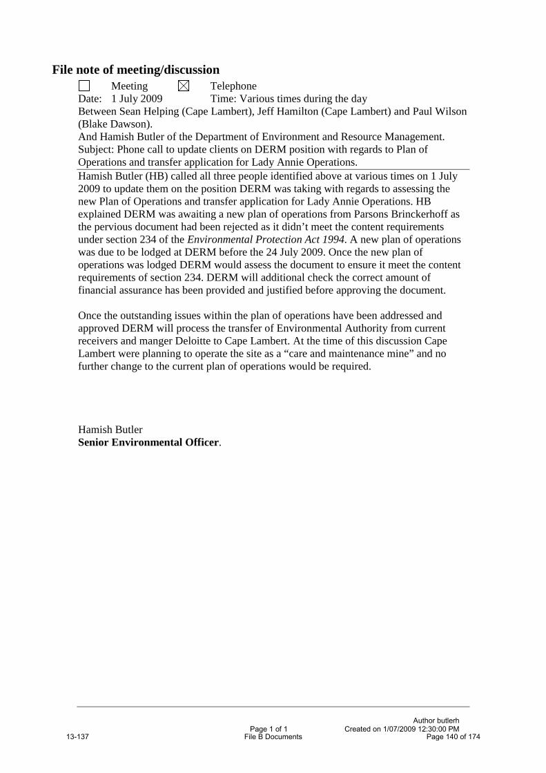
File note of meeting/discussionMeeting Telephone
Date: 1 July 2009 Time: Various times during the dayBetween Sean Helping (Cape Lambert), Jeff Hamilton (Cape Lambert) and Paul Wilson (Blake Dawson).And Hamish Butler of the Department of Environment and Resource Management.Subject: Phone call to update clients on DERM position with regards to Plan of Operations and transfer application for Lady Annie Operations.Hamish Butler (HB) called all three people identified above at various times on 1 July 2009 to update them on the position DERM was taking with regards to assessing the new Plan of Operations and transfer application for Lady Annie Operations. HB explained DERM was awaiting a new plan of operations from Parsons Brinckerhoff as the pervious document had been rejected as it didn’t meet the content requirements under section 234 of the Environmental Protection Act 1994. A new plan of operations was due to be lodged at DERM before the 24 July 2009. Once the new plan of operations was lodged DERM would assess the document to ensure it meet the content requirements of section 234. DERM will additional check the correct amount of financial assurance has been provided and justified before approving the document.
Once the outstanding issues within the plan of operations have been addressed and approved DERM will process the transfer of Environmental Authority from currentreceivers and manger Deloitte to Cape Lambert. At the time of this discussion Cape Lambert were planning to operate the site as a “care and maintenance mine” and no further change to the current plan of operations would be required.
Hamish ButlerSenior Environmental Officer.
Author butlerhPage 1 of 1 Created on 1/07/2009 12:30:00 PM
13-137 File B Documents Page 140 of 174

13-137 File B Documents Page 141 of 174
Released

13-137 File B Documents Page 142 of 174
s.49 - Signature

13-137 File B Documents Page 143 of 174
Released

13-137 File B Documents Page 144 of 174s.49 - Signature
13-137 File B Documents Page 145 of 174s.49 - Signature

13-137 File B Documents Page 146 of 174s.49 - Signature

13-137 File B Documents Page 147 of 174
s.49 - Signature

13-137 File B Documents Page 148 of 174s.49 - Signature

13-137 File B Documents Page 149 of 174 s.49 - Signature

13-137 File B Documents Page 150 of 174s.49 - Signature

13-137 File B Documents Page 151 of 1s.49 - Signature

13-137 File B Documents Page 152 of 174s.49 - Signature

13-137 File B Documents Page 153 of 174
s.49 - Signature

13-137 File B Documents Page 154 of 174s.49 - Signature

13-137 File B Documents Page 155 of 174 s.49 - Signature

File note inspection/discussionInspection Telephone
Date: 14/12/2009 Time: 2:30 to 4:00pmBetween Russ McConnell, Rod Kent of DERM
Warwick Fegan, Stuart Roberts of DERM (2:30 to 3:30pm)And David Cook of Cape Lambert Lady Annie Exploration -
EnvironmentManagerAllan Evans, Nick Anderson Engineers of PB Consultants
Subject: Pre-wet season inspection of site – Lady Annie Mine
Background: Lady Annie Mine had major discharges to the environment in January to February period 2009 and was issued with an Environmental Evaluation Notice.PB Consultants have been undertaking the evaluation on behalf of the mine operator, Deloitte Touche Tohmatsu, Receivers and Managers for the companies associated with the Lady Annie Mine. The response to the Evaluation Notice was issued on the 14/10/2009 by PB Consultants and submitted to DERM a short time afterwards.
The response was not complete in that the geotechnical investigation and assessment of the integrity of the liner had not yet been undertaken. The reasons given were the slowness of dewatering the “raw water pond”. The strategy, as understood from verbal communications, was to empty the raw water pond (RWP) and then transfer water from storm pond 2 (SP2) to the RWPso that the liner can be accessed.
DERM has been verbally advised the liner will not be lifted until after the wet season and that geotechnical investigations will take place then.
DERM has also been advised that some geotechnical investigations have already taken place but do not appear in the environmental evaluation.
DERM has concerns that there is currently some risk of further wet season release during the 2009/2010 wet season on the basis that:
(a) The Environmental Investigation has not identified the primary cause ofthe discharges from the mine site but assumes that it is driven by catchment size,
(b) There may be other contributory mechanisms which should be taken into account, and
(c) No corrective actions have been undertaken to prevent a recurrence of the 2009 releases should other mechanisms be present and a similar wet season occur even with the surface water diversion in place.
Actions:
In the absence of the Geotechnical Assessment required under the Environmental Evaluation Notice, DERM cannot determine if the risk of a re-occurrence of the discharges has been lowered to acceptable levels.
E:\Integrated Assessment\Dams\Docs\Mt Kelly\PBforMine\FileNote of Inspection of Mine 14-12-2009.docPage 1 of 5 Created on 21/12/2009 3:04:00 PM
13-137 File B Documents Page 156 of 174
PB supplied electronic copies of documentation describing diversion works about the site on 02/10/2009 and understand that these works have been put in place.
DERM has therefore sent a specialist dams engineer (Russ McConnell) to the site to assess the current situation.
Outcomes of Inspection:
The diversions, as described in the documentation, have been effectively completed. The rock protection has been installed and the walls of the diversion channels top soiled in preparation for grassing. These diversions will substantially reduce the size of the catchment reporting to the plant site area.
In essence the consultants are focussing of surface water entry to the ponds after failure of the bunds as being the main reason for the discharge. The opinion of the engineers at DERM is still that the water entry mechanism for the January February discharge has not been fully identified and resolved. Russ McConnell pointed out the photographic record of the flooding showed liner lifting well before failure of the bunds indicating ingress of groundwater from some source. It was further observed that Borehole BH06-7 contained lateritic gravel 1.5 to 3.3 m and is on the drainage line (Saga Creek).
The submitted EE states that recent revision calculations revealed that, while both were originally designed for Q100, the Southern Diversion could handle a Q1000 storm and the Northern Diversion could handle a Q500 storm.
The Raw Water Pond was currently empty (200 Ml capacity)
The site can currently manage a 1 in 300 wet season, having 480 Ml of storage available out of 770 Ml. This does not include the Raw Water Pond.
Mist evaporators were located on the intermediate bank between Storm Pond 1 and 2. Mist residue mostly fell in the storm ponds but could reach the unlined perimeter of the pond in stronger winds. The mist is highly acidic (personal communication DC).
Storm Pond 1 does not leak. (Not observable)
There is possibly a leak in Storm Pond 2 in the area of the water equalizer pipe.(Not observable)
The spillways have been repaired. The repairs were not inspected because of the proximity of the acid mist but it was noted that:
(a) The downstream apron of the spillway had been armoured with (dolomite ?) rock, presumably to prevent erosion and neutralize acidity, and
(b) Rock groynes had been placed across the spillway, presumably to limit flow velocity, neutralize acidity and to act as a sediment trap for precipitates and suspended solids.
E:\Integrated Assessment\Dams\Docs\Mt Kelly\PBforMine\FileNote of Inspection of Mine 14-12-2009.docPage 2 of 5 Created on 21/12/2009 3:04:00 PM
13-137 File B Documents Page 157 of 174

It was observed that the walls of the spillway apron and the groynes were not armoured. In particular, the walls at the ends of the groynes need to be armoured to prevent erosion opening up bypasses to the groynes.
The impact of the groynes on the flood capacity needs to be checked to ensure that backwater effects do not affect spillway capacity of the storm ponds.
It was observed that Storm Pond 2 contained a small pond of water in the north east corner. It was reported that persons had walked over the floor and that the floor was “soft” to walk where accessible. There was no evidence of gas under the liner.It was noted that the “sink” hole area had been filled but had not been investigated since February 2009.
It was noted that the liner in the eastern side of Storm Pond 2 had settled onto excavation batter and that horizontal folds in the liner were present in the areas where the initial floating of the liner occurred.
A number of sink holes were observed amongst the thicket of remnant vegetation immediately adjacent to the liner folding. An investigation trench was located between the thicket and the liner folding. It had been partially backfilled.While the material in the investigation trench contained little “gravel” a nearby mound did contain observable “gravel”, suggesting that “gravels” may be
present as paleo channels.
David Cook, Warwick Fegan and Stuart Roberts left the inspecting team at 3:30 pm.
E:\Integrated Assessment\Dams\Docs\Mt Kelly\PBforMine\FileNote of Inspection of Mine 14-12-2009.docPage 3 of 5 Created on 21/12/2009 3:04:00 PM
13-137 File B Documents Page 158 of 174

The Southern Diversion channel was inspected. The unarmoured batters of the diversion channel excavations had been topsoiled in preparation for grassing. No natural stratification was observable.
At about Chainage 300 on the Diversion Channel Chainage Datum, another area of sink holes was discovered in remnant vegetation between the diversion channel and the eastern bund wall of the heap leach pads. This was also thearea of major water pondage over the January February period of 2009. The sink holes were much larger and better defined than those adjacent to Storm Pond Number 2 suggesting that this may have been an area of major ingress of water into an aquifer or a subterranean flow path feature.
The linear alignment of the two sink hole areas and Borehole BH06-7(containing lateritic gravel 1.5 to 3.3 m) suggest that there could be a subterranean flow path feature connecting all three.
If gravels are present they may be present as lamellar inclusions in an otherwise fine soil profile. Investigations for such features requires the mapping of the soil stratigraphy in trench wall in the context of the soil formation processes.E:\Integrated Assessment\Dams\Docs\Mt Kelly\PBforMine\FileNote of Inspection of Mine 14-12-2009.doc
Page 4 of 5 Created on 21/12/2009 3:04:00 PM13-137 File B Documents Page 159 of 174
s.49

The existence or otherwise of a subterranean flow path feature needs to be investigated. If the feature exists then:
(a) The ingress of water into the feature needs to be prevented, or(b) The ingress of water from the feature into the storm ponds needs to be
prevented (eg by a cutoff), or(c) Ingressing water needs to be removed from the storm ponds at a rate
that prevents discharge to the environment.
The areal extent and characteristics of the sink hole areas need to be mapped. Areas of high density and strongly developed sink holes need to be investigated to establish the nature of the mechanism. An opportunity exists to examine the batters of the diversion channel to see if features can be identified. If rain occurs, the batters should be examined before the topsoil is replaced on the batters of the diversion channels. If rain does not occur then some topsoil should be removed to expose the natural stratigraphy. Otherwise, investigation trenches under the direction of a geotechnical engineer should be used in the areas of high density or strongly developed sink holes
The implication of the existence of such a feature is that surface water from outside the plant area will again find its way into the storm ponds and cause another discharge to the environment.
Inspection finished 4:00 pm
Russ McConnell 21 December 2009
E:\Integrated Assessment\Dams\Docs\Mt Kelly\PBforMine\FileNote of Inspection of Mine 14-12-2009.docPage 5 of 5 Created on 21/12/2009 3:04:00 PM
13-137 File B Documents Page 160 of 174

File note of meeting/discussionMeeting Telephone
Date: 16/11/2009 Time: 2:30 to 3:30 pmBetween Russ McConnell, Gary Hargraves, Warwick Fegan of DERMAnd Ellis Lawrie Project Manager
Brian FaitonFainton Senior Environmental ScientistJoe Major Geotechnical Engineerof PB Consultants
Subject: Technical Progress on Environmental Evaluation Notice – Lady Annie Mine
Background: Lady Annie Mine had major discharges to the environment in January to February period 2009 and were requested to undertake issued with anEnvironmental Evaluation Notice. PB Consultants have been undertaking the evaluation on behalf of the mine operator, Deloitte Touche Tohmatsu, Receivers and Managers for the companies associated with the Lady Annie Mine. The response to the Evaluation Notice was issued on the 14/10/2009 by PB Consultants and submitted to DERM a short time afterwards.
The response was not complete in that the geotechnical investigation and assessment of the integrity of the liner had not yet been undertaken. The reasons given wasreasons given were the slowness of dewatering the “rawclean water dampond”. The strategy, as understood from verbal communications, was to empty the clean raw water dam pond (CRWPD) and then transfer water from storm pond 2 (SP2) to the RCWPD so that the liner can be accessed.
DERM has been verbally advised the liner will not be lifted until after the wet season and that geotechnical investigations will take place then.
DERM has also been advised that some geotechnical investigations have already taken place but do not appear in the environmental evaluation.
DERM has concerns that there is currently some risk of further wet season release during the 2009/2010 wet season on the mine site will undergo further emissions this wet season on the basis that:
(a) The Environmental Investigation has not identified the primary cause ofthe discharges from the mine site,
(a)(b) Alternative or contributory mechanisms had not been ruled out,and
(b)(c) No corrective actions have been undertaken to prevent a recurrence of the 2009 releases should alternative mechanisms be present and a similar wet season occur.
Actions:
As a result of communications between Warwick Fegan and the Project Manager, this meeting was convened to get an understanding of the current status of site and the investigations taking place.
Comment [F1]: What is this trying to say??
Comment [F2]: Are we just trying to say that they have not thoroughly investigated all potential factors that caused the 2009 failure? Bit misleading this statement.
G:\Applications 13-14\Applications\13-101 - 13-150\13-137 - Vero Insurance\Documents\Master\ESR Nth\091611 a File note of meetinga.doc
Author mcconnrPage 1 of 4 Created on 18/11/2009 1:38:00 PM
13-137 File B Documents Page 161 of 174
PB supplied electronic copies of documentation describing diversion works about the site on 1102/110/2009.
Outcomes of meeting:
The diversions, as described in the documentation, were effectively completedtwo weeks ago with some minor amendments. Some of the rock protection is still being installed. These diversions will substantially reduce the size of the catchment reporting to the plant site area.
A geotechnical report has been and is currently with Deloitte Touche Tohmatsu.Joe Major described some of the contents of the report. It is understood that PB is of the opinion that for the heap leach area:
(a) The damage to Eastern Bund of the heap leach pad was wholly causedby erosion resulting from runoff from the service road and the conveyor belt corridor. No settlement or rotational failure had occurred. The HDPE liner was not compromised and no contaminated water escaped from the heap leach apron. Water seeping under the liner should have been natural runoff at background water quality (need to check if this was sampled).
(b) Six test pits were excavated along the bund at locations yet to be clearly identified in documentation. All contained several meters of clayey soils overlying a weathered mudstone bed.
(c) Joe thought that the amount of seepage passing under the liner shouldbe insignificant, and
that for the storm runoff water pond 2 area:
(a) The subsidence in the south east corner was initiated by cracking in the soils and water flows through the cracks (need to wait for the report on this one to see the supporting data).
(b) The inflows into the pond were caused by collapses (2) of bunds around the area.
(c) One test pit has been dug near the bund which showed a similar profile to those done along the heap leach levee. No gravels were found.
(d) The bunds in the area have been substantially widened.(e) Joe believes that seepage into the storm water ponds should be
“miniscule”.(f) A further test pit near the spillway revealed a change in soil lithology but
still no gravel. Joe indicated that soil types have been mapped in the area.
In essence the consultants are focussing of surface water entry to the ponds after failure of the bunds as being the main reason for the discharge. The opinion of the engineers at DERM is still that the water entry mechanism for the January February discharge has not been fully identified and resolved. Russ McConnell pointed out the photographic record of the flooding showed liner lifting well before failure of the bunds indicating ingress of groundwater from
G:\Applications 13-14\Applications\13-101 - 13-150\13-137 - Vero Insurance\Documents\Master\ESR Nth\091611 a File note of meetinga.doc
Author mcconnrPage 2 of 4 Created on 18/11/2009 1:38:00 PM
13-137 File B Documents Page 162 of 174

some source. It was further observed that Borehole BH06-7 contained lateritic gravel 1.5 to 3.3 m and is on the drainage line (Saga Creek).
Brian FaitonFainton stated that recent revision calculations revealed that, while both were originally designed for Q100, the Southern Diversion could handle a Q1000 storm and the Northern Diversion could handle a Q500 storm.
Brian FaitonFainton stated that the Raw Water Dam Pond was currently empty (200 Ml capacity)
The site can currently manage a 1 in 300 wet season, having 480 Ml of storage available out of 770 Ml. This does not include the Raw Water DamPond.
Storm Pond 1 does not leak.
There is possibly a leak in Storm Pond 2 in the area of the water equalizer pipe.
No groundwater bores show signs of contamination from storm water pond contents. (this needs to be validated).
Ellis Lawrie summarized proposed works, awaiting the endorsement of the receivers, as follows:
(a) Removal of remaining water from Storm Pond 2 ASAP from above and below the liner.
(b) Walkover survey of dewatered liner to see if there are silt trails, fans, cavities or other features that may need consideration in remediation works.
(c) Fixing of leaks in the liner for the coming wet season.(d) Investigation through the liner (resealable holes) of silt deposits,
cavities, soil contamination and other features.(e) Lifting the liner (if required) next dry season (This seams to be an idea
proposed by the consultants. Is it endorsed by DERM? Is there a reason to lift the liner? )
(The outstanding issue is “is there a real reason to lift the liner?”. On the basis of land contamination advice from Garry O’connorO’Connor is that water at the concentrations cited might not result in contaminated land. The total removal ofthe liners may not be necessary. It may be possible to undertake repairs in small areas or strips.)
Meeting finished 3:30 pm
Russ McConnell 16 November 2009
Comment [F3]: It is my understanding the liner will be replaced as there is some holes in it already.
G:\Applications 13-14\Applications\13-101 - 13-150\13-137 - Vero Insurance\Documents\Master\ESR Nth\091611 a File note of meetinga.doc
Author mcconnrPage 3 of 4 Created on 18/11/2009 1:38:00 PM
13-137 File B Documents Page 163 of 174
Released

File note of meeting/discussionMeeting Telephone
Date: 16/11/2009 Time: 2:30 to 3:30 pmBetween Russ McConnell, Gary Hargraves, Warwick Fegan of DERMAnd Ellis Lawrie Project Manager
Brian Fainton Senior Environmental ScientistJoe Major Geotechnical Engineerof PB Consultants
Subject: Technical Progress on Environmental Evaluation Notice – Lady Annie Mine
Background: Lady Annie Mine had major discharges to the environment in January to February period 2009 and were issued with an Environmental EvaluationNotice. PB Consultants have been undertaking the evaluation on behalf of the mine operator, Deloitte Touche Tohmatsu, Receivers and Managers for the companies associated with the Lady Annie Mine. The response to the Evaluation Notice was issued on the 14/10/2009 by PB Consultants and submitted to DERM a short time afterwards.
The response was not complete in that the geotechnical investigation and assessment of the integrity of the liner had not yet been undertaken. The reasons given were the slowness of dewatering the “raw water pond”. The strategy, as understood from verbal communications, was to empty the raw water pond (RWP) and then transfer water from storm pond 2 (SP2) to the RWPso that the liner can be accessed.
DERM has been verbally advised the liner will not be lifted until after the wet season and that geotechnical investigations will take place then.
DERM has also been advised that some geotechnical investigations have already taken place but do not appear in the environmental evaluation.
DERM has concerns that there is currently some risk of further wet season release during the 2009/2010 wet season on the basis that:
(a) The Environmental Investigation has not identified the primary cause ofthe discharges from the mine site but assumes that it is driven by catchment size,
(a)(b) There may be other contributory mechanisms which should be taken into account, and
(b)(c) No corrective actions have been undertaken to prevent a recurrence of the 2009 releases should other mechanisms be present and a similar wet season occur even with the surface water diversion in place.
Actions:
As a result of communications between Warwick Fegan and the Project Manager, this meeting was convened to get an understanding of the current status of site and the investigations taking place.
G:\Applications 13-14\Applications\13-101 - 13-150\13-137 - Vero Insurance\Documents\Master\ESR Nth\091611 b File note of meeting.doc
Author mcconnrPage 1 of 4 Created on 18/11/2009 1:53:00 PM
13-137 File B Documents Page 164 of 174
Released

PB supplied electronic copies of documentation describing diversion works about the site on 02/10/2009.
Outcomes of meeting:
The diversions, as described in the documentation, were effectively completedtwo weeks ago with some minor amendments. Some of the rock protection is still being installed. These diversions will substantially reduce the size of the catchment reporting to the plant site area.
A geotechnical report has been and is currently with Deloitte Touche Tohmatsu.Joe Major described some of the contents of the report. It is understood that PB is of the opinion that for the heap leach area:
(a) The damage to Eastern Bund of the heap leach pad was wholly causedby erosion resulting from runoff from the service road and the conveyor belt corridor. No settlement or rotational failure had occurred. The HDPE liner was not compromised and no contaminated water escaped from the heap leach apron. Water seeping under the liner should have been natural runoff at background water quality (need to check if this was sampled).
(b) Six test pits were excavated along the bund at locations yet to be clearly identified in documentation. All contained several meters of clayey soils overlying a weathered mudstone bed.
(c) Joe thought that the amount of seepage passing under the liner shouldbe insignificant, and
that for the storm runoff water pond 2 area:
(a) The subsidence in the south east corner was initiated by cracking in the soils and water flows through the cracks (need to wait for the report on this one to see the supporting data).
(b) The inflows into the pond were caused by collapses (2) of bunds around the area.
(c) One test pit has been dug near the bund which showed a similar profile to those done along the heap leach levee. No gravels were found.
(d) The bunds in the area have been substantially widened.(e) Joe believes that seepage into the storm water ponds should be
“miniscule”.(f) A further test pit near the spillway revealed a change in soil lithology but
still no gravel. Joe indicated that soil types have been mapped in the area.
In essence the consultants are focussing of surface water entry to the ponds after failure of the bunds as being the main reason for the discharge. The opinion of the engineers at DERM is still that the water entry mechanism for the January February discharge has not been fully identified and resolved. Russ McConnell pointed out the photographic record of the flooding showed liner lifting well before failure of the bunds indicating ingress of groundwater from
G:\Applications 13-14\Applications\13-101 - 13-150\13-137 - Vero Insurance\Documents\Master\ESR Nth\091611 b File note of meeting.doc
Author mcconnrPage 2 of 4 Created on 18/11/2009 1:53:00 PM
13-137 File B Documents Page 165 of 174
Released

some source. It was further observed that Borehole BH06-7 contained lateritic gravel 1.5 to 3.3 m and is on the drainage line (Saga Creek).
Brian Fainton stated that recent revision calculations revealed that, while both were originally designed for Q100, the Southern Diversion could handle a Q1000storm and the Northern Diversion could handle a Q500 storm.
Brian Fainton stated that the Raw Water Pond was currently empty (200 Ml capacity)
The site can currently manage a 1 in 300 wet season, having 480 Ml of storage available out of 770 Ml. This does not include the Raw Water Pond.
Storm Pond 1 does not leak.
There is possibly a leak in Storm Pond 2 in the area of the water equalizer pipe.
No groundwater bores show signs of contamination from storm water pond contents. (this needs to be validated).
Ellis Lawrie summarized proposed works, awaiting the endorsement of the receivers, as follows:
(a) Removal of remaining water from Storm Pond 2 ASAP from above and below the liner.
(b) Walkover survey of dewatered liner to see if there are silt trails, fans, cavities or other features that may need consideration in remediation works.
(c) Fixing of leaks in the liner for the coming wet season.(d) Investigation through the liner (resealable holes) of silt deposits,
cavities, soil contamination and other features.(e) Lifting the liner (if required) next dry season (This seams to be an idea
proposed by the consultants. Is it endorsed by DERM? Is there a reason to lift the liner? )
(The outstanding issue is “is there a real reason to lift the liner?”. On the basis of land contamination advice from Garry O’Connor is that water at the concentrations cited might not result in contaminated land. The total removal of the liners may not be necessary. It may be possible to undertake repairs in small areas or strips.)
Meeting finished 3:30 pm
Russ McConnell 16 November 2009
Comment [F1]: It is my understanding the liner will be replaced as there is some holes in it already.
G:\Applications 13-14\Applications\13-101 - 13-150\13-137 - Vero Insurance\Documents\Master\ESR Nth\091611 b File note of meeting.doc
Author mcconnrPage 3 of 4 Created on 18/11/2009 1:53:00 PM
13-137 File B Documents Page 166 of 174
Released

13-137 File B Documents Page 167 of 174Released

13-137 File B Documents Page 168 of 174 Released

13-137 File B Documents Page 169 of 174
Released

13-137 File B Documents Page 170 of 174
s.49 - Signature

13-137 File B Documents Page 171 of 174
Released

13-137 File B Documents Page 172 of 174
Released

DISCUSSION POINTS FOR LADY ANNIE TELECONFERENCE
Firstly, Thank you to all the work done to date from everyone involved – Iunderstand that at times it has been difficultI thought it was important to convene a brief meeting with all relevant parties to ensure that everyone is clear on where the Department wishes to go with this site, and the work that needs to be doneOur goal is that by the end of the 2010 dry season, Lady Annie Mine will:
Have all water management infrastructure, protocols and procedures fully established in accordance with industry best practiceBe in full compliance with their environmental requirementsHave one clear entity responsible for the site
So I just wanted to touch on the areas the Department sees as requiring attention, so that action can occur in a proactive and timely fashion as soon as the wet season finishes
Remediation
The remediation of Saga and Inca Creek was not as effective as anticipated by the Department, therefore, the Department’s expectation is:
o Detailed monitoring occurs during and following wet season flowso A report is provided at the end of the wet detailing the levels, type
and distribution of any outstanding contamination in Saga and Inca Creek
o The Department would review the data and report on the contamination, and determine if further remediation is required in those creek systems
We also expect that the long term monitoring program (as per previous report) is carried out over the following wet seasons which include water quality data, sediment data and aquatic biology data.
Site Compliance
I would like to note that everyone who conducts works on a mine, has a responsibility to ensure the conditions of an Environmental Authority are complied with.
EEN Letter detailed that not all requirements of the Notice had been addressed in the reportDepartment expects details on the timeframes and responsible parties which addresses:
Geotechnical Assessment of the ponds and the heap leach padsDetails on how the water balance will be updated and calibrated over time with further data13-137 File B Documents Page 173 of 174

Accurate data to establish what wet season or rainfall events the site can contain
EPO1 (on site)Report and timeframe into the repair of SWP2 will be required to finalise matters relating to EPO1Important to start works as soon as possible into the dry season – don’t want this to run close to the following wet
EPO2 (Off site)Finalisation of EPO will await discussions of if any further remediation is requiredLong Term Monitoring program will still be required to be carried out aspreviously mentioned
EPO 3 (Red Mud)Further dams impacted by the discharge and treated with red mud will require removal of the sludge in consultation with landholder requirements
Constructed Inca Creek Dam was viewed during the helicopter survey to have one wall severely washed out – it is recommended that the landholder is engaged to determine the appropriate solution for the dam so that erosion is minimised
Sediment ErosionSediment erosion was viewed to be poorly managed on site during December and January inspections by the DepartmentThe stormwater diversion drains require particular attention to ensure they are stabilised and do not erode
Heap Leach Pads
Heap Leach Pads continue to be a concern - particularly the ability of the pads to contain contaminants within the lined area.Expectations are that investigations into the liner integrity and any potential sub surface contamination is quantifiedProgram of works established to ensure heap leach pads are operated correctly and comply with environmental requirements
13-137 File B Documents Page 174 of 174