Embed Size (px)
Citation preview

HL-17181-5
Motorized Linear Slides
EZS Series Actuator Edition
OPERATING MANUALThank you for purchasing an Oriental Motor product.This Operating Manual describes product handling procedures and safety precautions. • Please read it thoroughly to ensure safe operation. • Always keep the manual where it is readily available.
Table of contents
1 Introduction ..........................................21.1 Introduction ............................................. 21.2 Type and description for operating
manuals ................................................... 21.3 Equipped motor list ................................. 31.4 Checking the product .............................. 41.5 How to identify the product model ........... 51.6 Names and functions of parts ................. 61.7 Safety precautions .................................. 71.8 Precautions for use ............................... 10
2 Installation..........................................122.1 Location for installation ......................... 122.2 Installation direction .............................. 122.3 Installing the motorized linear slide ....... 122.4 Changing the motor cable outlet
direction ................................................. 142.5 How to install a load .............................. 18
3 Connection.........................................193.1 Connecting the driver ............................ 193.2 Grounding the motorized linear slide .... 19
3.3 When the electromagnetic brake type is used ................................................... 20
3.4 Connecting a sensor (Motorized linear slide equipped the AR Series) ............................................. 21
4 Maintenance ......................................224.1 Inspection item and timing .................... 224.2 Greasing ................................................ 244.3 Adjusting the belt tension and
replacing the belt ................................... 244.4 Replacing the motor .............................. 274.5 Adjusting the tension of the stainless
sheet ..................................................... 314.6 Warranty ................................................ 324.7 Disposal ................................................ 32
5 Standard, general specifications........335.1 Standard ................................................ 335.2 Specifications ........................................ 335.3 General specifications ........................... 33

Introduction
−2−
1 Introduction
1.1 IntroductionOnly qualified personnel should work with the product. Use the product correctly after thoroughly reading the separate operating manual "1.6 Safety precautions."The product described in this manual has been designed and manufactured to be incorporated in general industrial equipment. Do not use for any other purpose. Oriental Motor Co., Ltd. is not responsible for any damage caused through failure to observe the warning listed in the "1.6 Safety precautions."
1.2 Type and description for operating manualsThe composition of operating manuals for this product are described as follows. Operating manuals supplied with the product vary depending on the type of the product.
Motorized linear slides OPERATING MANUAL
(this document)
Read this manual before starting up your equipment.
Driver OPERATING MANUAL
USER MANUAL or OPERATING MANUAL
Function Edition
< How to obtain the operating manual > < Description >
Download∗2
Supplied withthe product
Supplied withthe product
This manual explains connections, setting methods, I/O signals and others.
Supplied withthe product∗1
This manual explains various functions, I/O signals, operation and others.
This manual explains safety precautions,installation methods, maintenance and others.
This manual is a recovery guide for when assuming to replace the motor at the time of maintenance.Recovery Guide
+
Download∗2
This manual explains the driver's parameters (moving direction, minimum travel amount) and functions for when combining various actuators.
Installation
Connection and setting
Connection and setting
Motorized actuator Function Setting Edition
*1 This manual is supplied with products that the AZ Series motor is equipped.*2 Please contact your nearest Oriental Motor sales office or download from Oriental Motor Website Download Page.

Introduction
−3−
1.3 Equipped motor listThese are the lists of the motor model names that are equipped in the EZS Series.The power supply current capacity, accessories and others of the drivers to be combined with the motorized linear slides are described in the Driver OPERATING MANUAL.Since the motor model names are described in the Driver OPERATING MANUAL, check by reference to those described in the tables.
• AC power input type • DC power input typeMotorized linear slide model Motor model Motorized linear slide model Motor model
EZSM3ARAC ARM46AC EZSM3ARAK ARM46SAK
EZSM3ARMC ARM46MC EZSM3ARMK ARM46SMK
EZSM4ARAC ARM46AC EZSM4ARAK ARM46SAK
EZSM4ARMC ARM46MC EZSM4ARMK ARM46SMK
EZSM6ARAC ARM66AC EZSM6ARAK ARM66SAK
EZSM6ARMC ARM66MC EZSM6ARMK ARM66SMK
EZSM3AZAC AZM46AC EZSM3AZAK AZM46AK
EZSM3AZMC AZM46MC EZSM3AZMK AZM46MK
EZSM4AZAC AZM46AC EZSM4AZAK AZM46AK
EZSM4AZMC AZM46MC EZSM4AZMK AZM46MK
EZSM6AZAC AZM66AC EZSM6AZAK AZM66AK
EZSM6AZMC AZM66MC EZSM6AZMK AZM66MK

Introduction
−4−
1.4 Checking the productVerify that the items listed below are included.Verify the model number of the purchased product against the number shown on the package label. Check the model number of the motorized linear slide and driver against the number shown on the nameplate. Report any missing or damaged items to the branch or sales office from which you purchased the product.
Motorized linear slides equipped the AR Series
When purchasing a motorized linear slide and driver package When purchasing a motorized linear slide only
• Motorized linear slide • Driver • Varistor *1 • Motorized Linear Slides OPERATING MANUAL (This document) • Driver OPERATING MANUAL • APPENDIX UL Standards *3 • Bolts for mounting the motorized linear slide (4 pieces) • A bag of connectors • Cable for motor *4 • Cable for electromagnetic brake *4(Supplied with electromagnetic brake types)
• Motorized linear slide • Varistor *2 • Motorized Linear Slides OPERATING MANUAL (This document) • APPENDIX UL Standards *3 • Bolts for mounting the motorized linear slide (4 pieces)
*1 This comes with the products if the driver that combines the "motorized linear slide with an electromagnetic brake" is the ARD-K.
*2 This comes with the DC power input type motorized linear slides with an electromagnetic brake that equipped the AR Series.
*3 Supplied with products conform to the UL Standards.*4 When the product is supplied with a connection cable.
Motorized linear slides equipped the AZ Series
When purchasing a motorized linear slide and driver package When purchasing a motorized linear slide only
• Motorized linear slide • Driver • Motorized Linear Slides OPERATING MANUAL (This document) • Driver OPERATING MANUAL • APPENDIX UL Standards *1 • Recovery Guide • Bolts for mounting the motorized linear slide (4 pieces) • A bag of connectors • Cable for motor *2 • Cable for electromagnetic brake *2(Supplied with electromagnetic brake types) • Cable for encoder *2
• Motorized linear slide • Motorized Linear Slides OPERATING MANUAL (This document) • APPENDIX UL Standards *1 • Recovery Guide • Bolts for mounting the motorized linear slide (4 pieces)
*1 Supplied with products conform to the UL Standards.*2 When the product is supplied with a connection cable.

Introduction
−5−
1.5 How to identify the product model
Motorized linear slide and driver package model
E Z S 4 R - E 0 5 0 - A R M K D - 1
E Z S 4 C L - E 0 5 0 - A R M K D - 1
1 2 3 5 6 7 108 9 11
1 2 4 5 6 7 108 9 11
Models for clean room use
1 Series name EZS: EZS Series
2 Motorized linear slide size3: Width 54 mm Height 50 mm 4: Width 74 mm Height 50 mm 6: Width 74 mm Height 66.5 mm
3 Motor mounting direction * R: Parallel motor mounting type (Right side) L: Parallel motor mounting type (Left side)Blank: In-line motor mounting type
4 Direction of air coupler for suction CR: Right CL: Left5 Ball screw lead D: 12 mm E: 6 mm 6 Stroke 005 ~ 085: 50 to 850 mm 7 Motor AR: AR Series AZ: AZ Series8 Motor type A: Single shaft M: With electromagnetic brake
9 Power supply input
Motorized linear slide equipped the AR SeriesA: Single-phase 100-120 VAC (Single-phase 100-115 VAC for the pulse input type)C: Single-phase 200-240 VAC (Single-phase 200-230 VAC for the pulse input type)S: Three-phase 200-230 VAC (For the pulse input type only)K: 24/48 VDC
Motorized linear slide equipped the AZ SeriesA: Single-phase 100-120 VACC: Single-phase/Three-phase 200-240 VACK: 24/48 VDC
10 Driver type D: Built-in controller type Blank: Pulse input type
11 Connection cable Number: Length of supplied cable 1: 1 m (3.3 ft.) 2: 2 m (6.6 ft.) 3: 3 m (9.8 ft.) Blank: Without connection cable
* There is no "parallel motor mounting type" for the products of the clean room use.
Motorized linear slide model
E Z S M 4 R E 0 5 0 A R M K
E Z S M 4 C L E 0 5 0 A R M K
1 2 3 5 6 7 8 9
1 2 4 5 6 7 8 9
Models for clean room use
1 Series name EZSM: EZS Series
2 Motorized linear slide size3: Width 54 mm Height 50 mm 4: Width 74 mm Height 50 mm 6: Width 74 mm Height 66.5 mm
3 Motor mounting direction * R: Parallel motor mounting type (Right side) L: Parallel motor mounting type (Left side) Blank: In-line motor mounting type
4 Direction of air coupler for suction CR: Right CL: Left
5 Ball screw lead D: 12 mm E: 6 mm 6 Stroke 005 ~ 085: 50 to 850 mm 7 Motor AR: AR Series AZ: AZ Series8 Motor type A: Single shaft M: With electromagnetic brake9 Motor power supply type C: AC power supply input K: DC power supply input
* There is no "parallel motor mounting type" for the products of the clean room use.

Introduction
−6−
1.6 Names and functions of parts
Names of cables
Cables of the motorized linear slides equipped the AR SeriesExample:AC power input type with electromagnetic brake
Motor mounting screw
Motor mounting screw
Tension adjusting screw
Tension adjusting spring
The motor is installed in the position where the belt is fixed with proper tension.
Springs for belt tension adjustment are installed.
Mechanism of the parallel motor mounting type
Pulley cover
Pulley
Belt
Models for clean room use
Motor
Table cover
Stainless sheet
Fastening plate for stainless sheet
Pulley cover
In-line motor mounting type
Parallel motormounting type
Side coverSide cover
Air coupler for suction
Motor cable
Electromagnetic brake cable
Protective earth terminalProtective earth terminal
Motor cableElectromagnetic brake cable
Encoder cable
Cables of the motorized linear slides equipped the AZ SeriesExample:AC power input type with electromagnetic brake

Introduction
−7−
1.7 Safety precautionsThe precautions described below are intended to prevent danger or injury to the user and other personnel through safe, correct use of the product. Use the product only after carefully reading and fully understanding these instructions.You must not operate the motorized actuator (operate the equipment for the specified purpose) if the machine in which the motorized actuator is installed does not satisfy the related safety standards.The factory safety manager or safety personnel in charge of the applicable machine must ensure that the machine is operated only by qualified personnel who are familiar with the operation of electronic equipment, and thereby prevent injury or damage to the equipment.The term “qualified personnel” refers to persons who have received the necessary training or education and have pertinent experience; who are familiar with the relevant standards, regulations, accident-prevention rules and inspection conditions; who are authorized by the factory safety manager to engage in the necessary activities; and who have the ability to discern and prevent potential dangers.
Description of signsHandling the product without observing the instructions that accompany a “Warning” symbol may result in death or serious bodily injury.Handling the product without observing the instructions that accompany a “Caution” symbol may result in bodily injury or property damage.
Note These notes appear throughout the manual and describe items that must be observed by the user to ensure correct use of the product.
Description of graphic symbolsIndicates "prohibited" actions that must not be performed.
Indicates "compulsory" actions that must be performed.
• Do not use the product in an atmosphere containing explosive, flammable or corrosive gases, in a place exposed to water, or near flammable objects. Doing so may result in fire, electric shock or injury.
• Do not perform operations such as transportation, installation, connection, inspection or maintenance while the power is on. Always turn the power off before carrying out these operations. Failure to do so may result in electric shock.
• Do not forcibly bend, pull or pinch the cable. Doing so may result in electric shock or fire.
• Do not disassemble or modify the product. Doing so may result in injury or damage to equipment.
• Never use a motorized linear slide in a medical device used in connection with the maintenance or management of human life or health, or in a transportation system whose purpose is to move or carry people.
• Be sure to provide a safety cage conforming to EN ISO 13857 to prevent persons from entering the moving range of the motorized linear slide while power is supplied to the motorized linear slide. Turn off the main power to the driver before performing adjustment or inspection in which the table is moved manually. Accidental contact may result in serious injury.
• Do not use the electromagnetic brake to decelerate, nor use it as a safety brake. Doing so may result in injury or equipment damage.
• Do not hit the table of the motorized linear slide to the mechanical stopper other than push-motion return-to-home operation and push-motion operation. Doing so may result in injury or damage to equipment.
• Assign qualified personnel the task of installing, wiring,operating/controlling, inspecting and troubleshooting the product. Failure to do so may result in fire, electric shock, injury or damage to equipment.
• If this product is used in an vertical application, be sure to provide a measure for the position retention of moving parts. Failure to do so may result in injury or damage to equipment.
• Operate the data setter outside the safety fence. Failure to do so may result in injury.
• When the driver generates an alarm (any of the driver's protective functions is triggered), take measures to hold the moving part in place since the motor stops and loses its holding torque. Failure to do so may result in injury or damage to equipment.

Introduction
−8−
• Install the products in the enclosure in order to prevent electric shock or injury
• The motor and driver are designed with Class I equipment basic insulation. When installing the motor, do not touch the product or be sure to ground them. Failure to do so may result in electric shock.
• Provide an emergency-stop device or emergency-stop circuit external to the equipment so that the entire equipment will operate safely in the event of a system failure or malfunction. Failure to do so may result in injury.
• Perform the return-to-home operation after the power is restored. If backing up the battery or using the motorized linear slide that equipped the AZ Series, perform the absolute positioning operation.Failure to do so may result in injury or equipment damage.
• Operate the motorized linear slide after setting the resolution, moving direction and other parameters. If the motorized linear slide is operated without setting parameters, the table may move to unexpected directions or run at unexpected speeds, causing injury or damage to equipment.(A variety of parameters have been set to the actuator that equipped the AZ Series at the time of shipment.)
• When the motor of the AZ Series is replaced at the time of maintenance, be sure to follow the procedures of the recovery guide. If the replacement is not performed in accordance with the procedures, the table may move to unexpected directions or run at unexpected speeds, causing injury or damage to equipment.
• After replacing the driver, set the resolution, moving (rotating) direction or other parameters before operating the motorized linear slide. If the motorized linear slide is operated without setting parameters, the table may move to unexpected directions or run at unexpected speeds, causing injury or damage to equipment.
• Do not use the product beyond its specifications Doing so may cause electric shock, injury or damage to equipment.
• Keep your fingers and objects out of the openings in the product. Failure to do so may result in fire, electric shock or injury.
• Do not touch the product while operating or immediately after stopping. Doing so may cause a skin burn(s).
• Do not carry the motorized linear slide by holding its cables or its moving part. Doing so may cause injury.
• Keep the area around the product free of combustible materials. Failure to do so may result in fire or a skin burn(s).
• Leave nothing around the product that would obstruct ventilation. Failure to do so may result in damage to equipment.
• Do not touch the moving part during operation. Doing so may cause injury.
• Do not touch the terminals while performing the insulation resistance test or dielectric strength test. Doing so may cause electric shock.
• Do not use the sensor set (accessory) as safety components. Doing so may result in injury or equipment damage.

Introduction
−9−
• Use a motorized linear slide and driver only in the specified combination. An incorrect combination may cause a fire.
• The motor surface temperature may exceed 70 ° C (158 ° F) even under normal operating conditions. If the operator is allowed to approach the running motor, attach a warning label as shown below in a conspicuous position. Failure to do so may result in a skin burn(s).
Warning label
• The motorized linear slide is very heavy. When transporting or installing the motorized actuator, make sure two persons work together to carry out the necessary tasks. Failure to do so may result in injury.
• Wear a helmet, safety shoes, gloves or other protective gear when transporting or installing the motorized actuator. Failure to do so may result in injury.
• When replacing the motor for the motorized linear slide, use the motor of the same model name that had been combined at the time of shipment. If a motor which series and size are different from the original one is combined, the actuator will not meet specifications and also injury or equipment damage may result.

Introduction
−10−
1.8 Precautions for useThis section covers limitations and requirements the user should consider when using the product.
General
• Be sure to use the cable (supplied or accessory) to connect the motorized linear slide and driver. In the following condition, an appropriate accessory cable must be purchased separately. ・If a flexible cable is to be used. ・If a cable of 3 m (9.8 ft.) or longer is to be used. ・If a motor and driver package without a cable was purchased.
• When conducting the insulation resistance measurement and the dielectric strength test, be sure to separate the connection between the motor and the driver. Conducting the insulation resistance measurement or withstand voltage test with the motorized actuator and driver connected may result in injury or damage to equipment.
• Do not make an impact with the motorized linear slide. Do not drop the motorized linear slide. Also, do not hit the motor or gear-reduction mechanism on something hard. Doing so may cause the positioning accuracy decrease, the motor section damage or the product service life reduction.
• Make sure not to hit or apply a strong impact on the encoder (ABZO sensor). ・Making a strong impact on an encoder (ABZO sensor) may cause the motor malfunction or damage to the encoder (ABZO sensor).・When transporting the motorized linear slide or installing a load, handle the motorized linear slide carefully not to make a strong impact on the moving part. ・The warning label shown in the right is indicated on the motor part of the motorized linear slides equipped with the AZ Series. Warning label
Temperature
• Use the motorized linear slide equipped the AR Series in conditions where its surface temperature will not exceed 100 ° C (212 ° F). The driver has an overheat protection function, but the motor has no such feature. The motor surface temperature may exceed 100 ° C (212 ° F) under certain conditions (ambient temperature, operating speed, duty cycle, etc.).To prevent the motor bearings (ball bearings) from reaching its usable life quickly, use the motor in conditions where the surface temperature will not exceed 100 ° C (212 ° F).
• Use the motorized linear slide equipped the AZ Series in conditions where its surface temperature will not exceed 80 ° C (176 ° F). The surface temperature on the motor case may exceed 80 ° C (176 ° F) depending on operating conditions such as ambient temperature, operating speed, duty cycle and others. In order to protect the encoder, use the motor so that the surface temperature on the motor case does not exceed 80 ° C (176 ° F).If the encoder temperature reaches the upper limit, the motor overheat protection alarm will generate.
Operation
• In the case of the DC power input type products, the maximum speed may not be reached depending on the ambient temperature or the length of the motor cable.
• Holding torque at standstill When the motorized linear slide stops, the holding torque of the output table will be reduced by the current cutback function of the driver. When selecting the motorized linear slide, make sure the holding torque at standstill by checking the catalog specification.
• Do not use the electromagnetic brake to reduce speed or as a safety brake. Do not use the electromagnetic brake as a means to decelerate and stop the motorized linear slide. The brake hub of the electromagnetic brake will wear significantly and the braking force will drop if used to stop the motor. The electromagnetic brake is a power-off activated type. This means that although it helps maintain the position of the load in the event of power outage, etc., this brake cannot securely hold the load in place. Accordingly, do not use the electromagnetic brake as a safety brake. To use the electromagnetic brake to hold the load in place, do so after the motorized linear slide has stopped.

Introduction
−11−
Notes for when the connection cable is usedNote the following points when a supplied cable or an accessory cable is used.
• When inserting the connector
Hold the connector main body, and insert it in straight securely.Inserting the connector in a inclined state may result in damage to terminals or a connection failure.
• When pulling out the connectorPull out the connector in straight while releasing the lock part of the connector. Pulling out the connector with holding the cable (lead wire) may result in damage to the connector.
• Bending radius of cable
Use the cable in a state where the bending radius of the cable is more than 6 times of the cable diameter.In the case of the lead wire type, use in a state where the bending radius is more than 4 times of the diameter of the lead wires.
More than 6 times of cable diameter
• How to fix the cableFix the cable at the positions near the connector so as to apply no stress on the connector part.Take measures so as to apply no stress on the connector by using wide clamps or by fixing at two places.
In the case of a exible cable, this area is a movable range.
Fix
Fix

Installation
−12−
2 Installation
2.1 Location for installationThe motorized actuator has been designed and manufactured to be incorporated in general industrial equipment. Install it in a well-ventilated location that provides easy access for inspection. The location must also satisfy the following conditions. • Inside an enclosure that is installed indoors (provide vent holes) • Operating ambient temperature: 0 to +40° C (+32 to 104° F) (non-freezing) • Operating ambient humidity: 85% or less (non-condensing) • Area that is free of explosive atmosphere or toxic gas (such as sulfuric gas) or liquid • Area not exposed to direct sun • Area free of excessive amount of dust, iron particles or the like • Area not subject to splashing water (rain, water droplets), oil (oil droplets) or other liquids • Area free of excessive salt • Area not subject to continuous vibration or excessive shocks • Area free of excessive electromagnetic noise (from welders, power machinery, etc.) • Area free of radioactive materials, magnetic fields or vacuum • Up to 1000 m (3300 ft.) above sea level
2.2 Installation directionThe motorized linear slide can be installed in any direction.
2.3 Installing the motorized linear slideTo prevent vibration and deflection of the linear slide, install it on a metal surface of sufficient strength.
Installation method using the mounting reference surfacesInstall the motorized linear slide while pressing the mounting reference surfaces provided on the base of the linear slide to the positioning pins that had set on the mounting plate.
• Mounting reference surfaces on the base of the motorized linear slide
A
BMounting reference surface
Positioning pin( 3mm or less)
EZS3 EZS4,EZS6 EZS3 EZS4,EZS6A B
Mounting reference surface Mounting reference surface
Positioning pins pressing position

Installation
−13−
Install while pressing the mounting reference surfaces of the guide rail to two positioning pins.
a
a
Cross-section view of the line a-a'
Positioning pinMounting reference surfaces of guide railGuide rail
Mounting plate
Mounting methodSecure the motorized linear slide from the upper side in addition to the back side of the mounting plate using screws.
6 mm or less
4 mm or less
Tightening torqueM5 5 N m (708 oz-in)
Positioning pin
Positioning pin
Flatness per 200 mm
Mounting plate (※ rough indication)
Tightening torqueM5 5 N m (708 oz-in)
※ This is the minimum value to require for installation. Determine the thickness of the mounting plate in consideration of the conditions such as load condition, rigidity, vibration and others.
Bolts for mounting (Supplied with the product)
Mounting plate: Aluminum
Thickness[mm]
0.05 mm or less
0.06 mm or less
Bolts for mounting (Supplied with the product) L [mm]
EZS3M5 45 8
12
10 or moreEZS4
EZS6 M5 65
Bolts for mounting
L

Installation
−14−
2.4 Changing the motor cable outlet directionThe motor cable outlet direction can be changed according to the equipment.
• When changing the motor cable outlet direction, remove the load and keep the motorized linear slide in a horizontal position. Doing the operation in a vertical condition may cause injury or damage to equipment.
• Doing the operation in a vertical condition may allow the moving part of the motorized linear slide to fall.• Removing the screws fixed the motor in a vertical condition may cause the motor itself to rotate.
• Operating the motorized linear slide without setting the home position again may cause the moving part to move unexpectedly, resulting in injury or damage to equipment.
• The moving part of the motorized linear slide may collide with the mechanical stopper.• The load may collide with other equipment.
• Be sure to secure the coupling and pulley with the specified tightening torque. If they are not secured with the specified torque, the ball screw may rotate idly, causing injury or damage to equipment.
• When the motorized linear slide is used in a vertical condition, the load may fall.• When the motorized linear slide is used in a horizontal condition, the moving part of the motorized linear
slide may collide with the mechanical stopper. Also, the load may collide with other equipment.
Note • Since the coupling fixing screw is small, handle it carefully.
• Keep the tightening torque.• Do not insert a hex key at a slant.• Do not use the ball-end hex key.
• To prevent the coupling fixing screw from falling off, keep three turns or less when loosening it.
In-line motor mounting type
① Remove the cap and loosen the screws of the coupling.
hexagonal socket head screw : M1.6
coupling
capcap
EZS3EZS4
EZS6
3 turns or less
3 turns or less
screw size : M2.5

Installation
−15−
② Loosen the screw that is secured the motor, and change the outlet direction of the cable.
Motor mounting screw4 locations, M3
EZS3EZS4
EZS6
Motor mounting screw4 locations, M4
③ When installing the motor, perform the reverse procedure to removing the motor. (②→①) Refer to the table below for the tightening torque of the coupling and motor mounting screw.
Tightening torquecoupling mounting screw motor mounting screw
EZS3, EZS4 M1.6 0.25 N‧m (35 oz-in) M3 1 N‧m (142 oz-in)EZS6 M2.5 1 N‧m (142 oz-in) M4 2.4 N‧m (340 oz-in)
④ After the motor cable outlet direction has been changed, set the home position again.

Installation
−16−
Parallel motor mounting type
90°
90°
Tightening torqueM3 1 N m (142 oz-in)
Motor mounting screw
Motor mounting screw
Tension adjusting screw
Tension adjusting spring
EZS3EZS4
For the parallel motor mounting type, the motor can be installed in three different directions.
Tighten the screws with pressingthe motor in the direction of arrowsso that the motor does not tilt.
3 turns or less
Tightening torqueM3 1 N m (142 oz-in) Tightening torque
M3 1 N m (142 oz-in)
When loosening screws, the tension of the belt will be adjusted properly by the strength of springs.
Tentatively mount the motor so that the motor can be shifted slightly.
After the motor cable outlet direction has been changed, set the home position again.

Installation
−17−
EZS6 Tightening torqueM3 1 N m (142 oz-in)
Tension adjusting screw
Tension adjusting spring
90°
90°
For the parallel motor mounting type, the motor can be installed in three different directions.
Tightening torqueM4 2.4 N m (340 oz-in) Tightening torque
M4 2.4 N m (340 oz-in)
Tentatively mount the motor so that the motor can be shifted slightly.
When loosening screws, the tension of the belt will be adjusted properly by the strength of springs.
3 turns or less
Tighten the screws with pressingthe motor in the direction of arrowsso that the motor does not tilt.
After the motor cable outlet direction has been changed, set the home position again.

Installation
−18−
2.5 How to install a loadInstall a load with screws using the load-mounting screw hole in the table.
For the load-mounting screw, be sure not to screw deeper than the length of 8 mm (0.31 in.) in the table. Doing so may cause the table to break, resulting in injury or damage to equipment.
Note Be sure to secure positioning pins to a load side. Securing the positioning pins to the table may damage the mechanism part due to impact or an excessive moment of inertia.
Holes of positioning pinDiameter Ø3 mmDepth 4 mm
+0.014 0
M4 2.4 N m (340 oz-in) Tightening torque
M5 5 N m (708 oz-in)EZS3,EZS4EAS6
8 mm or less

Connection
−19−
3 Connection
3.1 Connecting the driverFor details about the connection method of the driver as well as the wiring distance between the actuator and driver, refer to the Driver OPERATING MANUAL or USER MANUAL.
3.2 Grounding the motorized linear slide
Note • When multiple linear slides are used in combination, ground each linear slide.
• Do not share the grounding wire with a welder or any other power equipment.
• When grounding, use a round terminal and secure it with a mounting screw with a washer.
• Ground wires and crimp terminals are not supplied.
Motorized linear slide equipped the AR SeriesIf the DC power input type is used at 48 VDC or the AC power input type is used, be sure to ground the protective earth terminal of the motor. • Grounding wire:AWG18(0.75 mm2)or more • Screw size of the protective earth terminal:M4 • Tightening torque:1.2 N·m (170 oz-in)
PE
Motorized linear slide equipped the AZ Series
1. If the DC power input type is used at 48 VDC or the AC power input type is used, connect the grounding wire of the "cable for motor" to the driver protective earth terminal.
2. Ground the driver Protective Earth Terminal.Refer to the Driver OPERATING MANUAL for how to ground the driver.
3. Since the AZ Series has a grounding lead wire in the cable, it is possible to ground through the driver. However, the grounding resistance required by the standards applied to equipment may not be satisfied depending on the type or length of the motor cable. Ground using the protective earth terminal of the motor as necessary. • Grounding wire:AWG18(0.75 mm2)or more • screw size of the protective earth terminal:M4 • Tightening torque:1.2 N·m (170 oz-in)
PEPE
Even when the protective earth terminal of the motor is grounded, be sure to ground the driver.
PE
Connect the "cable for motor" to the motor connector on the driver.
Cable for motorCable for motor
Connect the groundingwire to the driver Protective Earth Terminal
AC Power Input Type DC Power Input Type
• Reference: Grounding wire of the "cable for motor" • Conductor size: AWG18 (0.75 mm2) • Maximum conductor resistance: 21.8 Ω/km (25.6 Ω/km for a flexible cable)

Connection
−20−
3.3 When the electromagnetic brake type is usedWhen moving the table of the motorized linear slide with an electromagnetic brake for adjusting the position or others, release the electromagnetic brake using a DC power supply for the electromagnetic brake.
How to release an electromagnetic brake
1. Connect the "electromagnetic brake cable" and supplied "cable for electromagnetic brake."
2. Connect the lead wires of the "cable for electromagnetic brake" to the 24 VDC power supply. Connect the white lead wire to the +24 VDC terminal, and the black lead wire to the GND terminal.When turning on the power, the electromagnetic brake will be released and the table will be able to move by hand.
Cable for electromagnetic brake
Motor cable
Electromagnetic brake cable 24 VDC ± 5% ∗1
0.08 A or more (EZS3,EZS4)0.25 A or more (EZS6)
DC power supplySwitchWhite
BlackVaristor ∗2
*1 If the distance between the "motorized linear slide with an electromagnetic brake" and driver is extended to 20 m (65.6 ft.) or longer, use a power supply of 24 ± 4% VDC.
*2 Connect the varistor to protect the contact of the switch or to prevent electrical noise. [Recommended varistor: Z15D121 (SEMITEC Corporation)]
Note Connect the lead wires of the electromagnetic brake in the correct polarities since they have polarities. Connecting the lead wires in wrong polarities will not properly operate the electromagnetic brake.

Connection
−21−
3.4 Connecting a sensor (Motorized linear slide equipped the AR Series)
This section explains examples for how to connect the driver and accessory sensor set. For details, refer to the OPERATING MANUAL of the sensor set and Driver OPERATING MANUAL.
Connection example for the home-sensor set PAES-S (NPN type)The connection example is shown based on the following conditions.
• Return-to-home method: 3 sensors • Logic of +LS output, −LS output: Normally closed • Logic of HOME output: Normally open
24 VDC
+LS
-LS
HOMES
IN-COM2
Sensor I/O
1 kΩ
1 kΩ
1 kΩ
4.4 kΩ
4.4 kΩ
4.4 kΩ
0 V
BrownPink ∗BlackBlue
BrownPink ∗BlackBlue
BrownPink ∗BlackBlue
Built-in controller type driver(Driver model ARD-KD, ARD-AD, ARD-CD)
PAES-S(NPN type)
* The logic of the sensor varies depending on the connection method. When the pink color lead is connected to the brown color lead, the sensor logic will be "normally closed.
Connection example for the home-sensor set PAES-SY (PNP type)The connection example is shown based on the following conditions.
• Return-to-home method: 3 sensors • Logic of +LS output, −LS output: Normally closed • Logic of HOME output: Normally open
24 VDC
+LS
-LS
HOMES
IN-COM2
Sensor I/O
1 kΩ
1 kΩ
1 kΩ
4.4 kΩ
4.4 kΩ
4.4 kΩ
0 V
BrownPink ∗
BlackBlue
BrownPink ∗
BlackBlue
BrownPink ∗
BlackBlue
Built-in controller type driver(Driver model ARD-KD, ARD-AD, ARD-CD)
PAES-SY(PNP type)
* The logic of the sensor varies depending on the connection method. When the pink color lead is connected to the brown color lead, the sensor logic will be "normally closed.
Maintenance
−22−
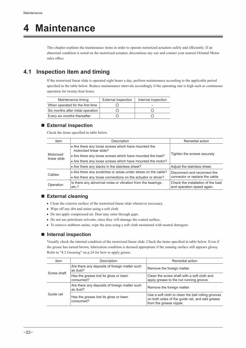
4 Maintenance
This chapter explains the maintenance items in order to operate motorized actuators safely and efficiently. If an abnormal condition is noted on the motorized actuator, discontinue any use and contact your nearest Oriental Motor sales office.
4.1 Inspection item and timingIf the motorized linear slide is operated eight hours a day, perform maintenance according to the applicable period specified in the table below. Reduce maintenance intervals accordingly if the operating rate is high such as continuous operation for twenty-four hours.
Maintenance timing External inspection Internal inspectionWhen operated for the first time –Six months after initial operation
Every six months thereafter
External inspectionCheck the items specified in table below.
Item Description Remedial action
Motorized linear slide
• Are there any loose screws which have mounted the motorized linear slide? • Are there any loose screws which have mounted the load? • Are there any loose screws which have mounted the motor?
Tighten the screws securely.
• Are there any slacks in the stainless sheet? Adjust the stainless sheet.
Cables • Are there any scratches or areas under stress on the cable? • Are there any loose connections on the actuator or driver?
Disconnect and reconnect the connector or replace the cable.
Operation Is there any abnormal noise or vibration from the bearings, etc.?
Check the installation of the load and operation speed again.
External cleaning • Clean the exterior surface of the motorized linear slide whenever necessary. • Wipe off any dirt and stains using a soft cloth. • Do not apply compressed air. Dust may enter through gaps. • Do not use petroleum solvents, since they will damage the coated surface. • To remove stubborn stains, wipe the area using a soft cloth moistened with neutral detergent.
Internal inspectionVisually check the internal condition of the motorized linear slide. Check the items specified in table below. Even if the grease has turned brown, lubrication condition is deemed appropriate if the running surface still appears glossy. Refer to "4.2 Greasing" on p.24 for how to apply grease.
Item Description Remedial action
Screw shaft
Are there any deposits of foreign matter such as dust? Remove the foreign matter.
Has the grease lost its gloss or been consumed?
Clean the screw shaft with a soft cloth and apply grease to the nut running groove.
Guide rail
Are there any deposits of foreign matter such as dust? Remove the foreign matter.
Has the grease lost its gloss or been consumed?
Use a soft cloth to clean the ball rolling grooves on both sides of the guide rail, and add grease from the grease nipple.

Maintenance
−23−
Checking the belt (When using the parallel motor mounting type)Remove the pulley cover to check the belt condition.Replace the belt if the following condition can be checked at the time of maintenance. Refer to "4.3 Adjusting the belt tension and replacing the belt" on p.24 for how to replace the belt.
Inspection interval Every 500 km (310 mi) in mileage
Inspection item • Is there any crack on the belt rubber? • Is there any stripped teeth on the belt? • Is there any abnormal abrasion on facing fabric of the belt?
• How to remove and install the pulley cover
Tightening torqueM3 1 N m (142 oz-in)

Maintenance
−24−
4.2 GreasingApply grease as an indication of the greasing timing in the table below.
Re-greasing Interval Type of grease Grease amount
Ball-screw shaft • Every six months • Every 100 km (62 mi) in mileage • When grease becomes extremely dirty
AFF grease (THK CO., LTD.) Apply grease lightly to the ball
screw and guide rail. If grease was applied too much, wipe the excess grease so that grease does not spatter.
• Models for clean room useAFE-CA grease (THK CO., LTD.)
Guide rail AFF grease (THK CO., LTD.)
• Wear protective goggles when applying grease. Pay attention to safety and handle the grease carefully by following the instructions provided with that product. If grease gets into the eyes or comes in contact with the skin, immediately flush the area thoroughly with water.
• When applying grease, do not touch the end section of the stainless sheet with bare hands. Doing so may result in injury.
• How to remove the side cover
Side cover
Grease application position of guide railSide surface of guide rail
Grease application position of ball screw
Tightening torqueM3 1 N m (142 oz-in)
4.3 Adjusting the belt tension and replacing the belt
• When performing tension adjustment or replacement of the belt, remove the load and keep the motorized linear slide in a horizontal position. Doing the operation in a vertical condition may allow the moving part to fall, causing injury or damage to equipment.
• Operating the motorized linear slide without setting the home position again may cause the moving part to move unexpectedly, resulting in injury or damage to equipment.• The moving part of the motorized linear slide may collide with the mechanical stopper.• The load may collide with other equipment.
• Perform the belt tension adjustment in the order of ①→②→⑤→⑥ . • Perform the belt replacement in the order of ①→②→③→④→⑤→⑥ . For the belt for maintenance, contact your nearest Oriental Motor office.
Motorized linear slide model Belt modelEZS3, EZS4 LS-LVCS2M060186
EZS6 LS-LVCS3M080252

Maintenance
−25−

Maintenance
−26−

Maintenance
−27−
4.4 Replacing the motor
• When replacing the motor, remove the load and keep the motorized linear slide in a horizontal position. Doing the operation in a vertical condition may cause injury or damage to equipment.
• Doing the operation in a vertical condition may allow the moving part of the motorized linear slide to fall.• Removing the screws fixed the motor in a vertical condition may cause the motor itself to rotate.
• Be sure to secure the coupling and pulley with the specified tightening torque. If they are not secured with the specified torque, the ball screw may rotate idly, causing injury or damage to equipment.
• When the motorized linear slide is used in a vertical condition, the load may fall.• When the motorized linear slide is used in a horizontal condition, the moving part of the motorized linear
slide may collide with the mechanical stopper. Also, the load may collide with other equipment.
• For the motorized linear slide equipped the AZ Series, perform maintenance according to the separate manual "Read this manual before starting up your equipment Recovery Guide" or "Motorized actuator Function Setting Edition." If the motorized linear slide is operated immediately after replacing the motor only, since the optimal parameters have not set to the driver, it may move to unexpected directions or run at unexpected speeds, causing injury or damage to equipment.
• Operating the motorized linear slide without setting the home position again may cause the moving part to move unexpectedly, resulting in injury or damage to equipment.
• The moving part of the motorized linear slide may collide with the mechanical stopper.• The load may collide with other equipment.
Note • Since the coupling fixing screw is small, handle it carefully.
• Keep the tightening torque.• Do not insert a hex key at a slant.• Do not use the ball-end hex key.
• To prevent the coupling fixing screw from falling off, keep three turns or less when loosening it.
In-line motor mounting type
① Open the cap and loosen the screws of the coupling.
hexagonal socket head screw : M1.6
coupling
capcap
EZS3EZS4
EZS6
3 turns or less
3 turns or less
screw size : M2.5

Maintenance
−28−
② Remove the motor by loosening the screws (4 locations) that are secured the motor.
EZS3EZS4
EZS6
Motor mounting screw4 locations, M4
Motor mounting screw4 locations, M3
③ When installing the motor, perform the reverse procedure to removing the motor. (②→①) Refer to the table below for the tightening torque of the coupling and motor mounting screw.
Tightening torquecoupling mounting screw motor mounting screw
EZS3,EZS4 M1.6 0.25 N‧m (35 oz-in) M3 1 N‧m (142 oz-in)EZS6 M2.5 1 N‧m (142 oz-in) M4 2.4 N‧m (340 oz-in)
④For the motorized linear slide equipped the AZ Series, perform maintenance according to the separate manual "Read this manual before starting up your equipment Recovery Guide" or "Motorized actuator Function Setting Edition."
⑤ Set the home position again after replacing the motor.

Maintenance
−29−
Parallel motor mounting type
When the motor is removed, the belt canbe removed.
Remove the motor by loosening the screws(4 locations) that are secured the motor.
A
Install the pulley to the new motor.
Fix the screw at the location otherthan the shaft flat on the motor shaft.
EZS3,EZS4
EZS6
18.5
20.5
LS-LSPTP1709
LS-LSPTP1710
Dimension A[mm]
Tightening torque[N m] (oz-in)
Screw size
Model name of pulley for maintenance
0.8 (113 ) M3
1.7 (241) M4
shaft flat
Use the following accessories (sold separately) for the pulley replacement.

Maintenance
−30−
Tentatively mount the motor so that the motor can be shifted slightly. After tentatively attaching the motor, perform steps ( → → → ) according to p.22 "Adjusting the belt tension and replacing the belt."
For the motorized linear slide equipped the AZ Series, perform maintenance according to the separate manual "Read this manual before starting up your equipment Recovery Guide."
Set the home position again after replacing the motor.
Tightening torqueEZS3,EZS4 : M3 1 N m (142 oz-in)EZS6 : M4 2.4 N m (340 oz-in)

Maintenance
−31−
4.5 Adjusting the tension of the stainless sheetIf the stainless sheet is slacked, tighten and take up the slack of the stainless sheet.
When adjusting the tension of the stainless sheet, do not touch the end section of the stainless sheet with bare hands. Doing so may result in injury.
Loosen screws of the position A or B.
When loosening the position BWhen loosening the position A
AM3 hexagonal socket head screw (2 pcs)
BM5 hexagonal socket set screw (2 pcs)
Pull the stainless sheet in the direction of the arrow while holding down it by hand to take up its slack.
Tighten the loosened screws.
Move the table manually and check that there is no slack in the stainless sheet.
Tightening torque1 N m (142 oz-in.)

Maintenance
−32−
4.6 WarrantyCheck on the Oriental Motor Website or General Catalog for the product warranty.
4.7 DisposalDispose the product correctly in accordance with laws and regulations, or instructions of local governments.

Standard, general specifications
−33−
5 Standard, general specifications
5.1 Standard
UL Standard and CSA StandardCheck the “APPENDIX UL Standards” of each product for recognition information about UL Standards of the equipped motor.
EU Directives
• CE MARKINGMotors for the EZS Series AC power input type are affixed the CE Marking under the Low Voltage Directive and EMC Directive.
Low Voltage DirectiveApplied Standards EN 60034-1, EN 60034-5, EN 60664-1
For the actuators equipped with the AR Series, they are certified by TÜV Rheinland under the EN 60034-1 and EN 60034-5.
Hazardous substancesThe products do not contain the substances exceeding the restriction values of RoHS Directive (2011/65/EU).
Machinery DirectiveThe motorized actuator and driver have been designed and manufactured to be incorporated in general industrial equipment, and a Declaration of Incorporation of Partly Completed Machinery is issued with them according to the Machinery Directive. • Applicable standard: EN ISO 12100
5.2 SpecificationsCheck on the Oriental Motor Website for the product specifications.
5.3 General specifications
Installation conditionsThe product described in this manual has been designed and manufactured to be incorporated in general industrial equipment.
Input power supply DC power supply AC power supplyOvervoltage category Ⅱ
Protection against electric shock Class Ⅰ equipmentPollution degree 2 3Degree of protection IP20Noise level 72 dB

Standard, general specifications
−34−
Environmental conditions
Operating environment Storage environment Shipping environment
Ambient temperature 0 to +40 (+32 to +104° F) (non-freezing) –20 to +60 (–4 to +140° F) (non-freezing)
Ambient humidity 85% or less (non-condensing)
Altitude Up to 1000 m (3300 ft.) above sea level Up to 3000 m (10000 ft.) above sea level

−35−

• Unauthorized reproduction or copying of all or part of this manual is prohibited. If a new copy is required to replace an original manual that has been damaged or lost, please contact your nearest Oriental Motor branch or sales office.
• Oriental Motor shall not be liable whatsoever for any problems relating to industrial property rights arising from use of any information, circuit, equipment or device provided or referenced in this manual.
• Characteristics, specifications and dimensions are subject to change without notice. • While we make every effort to offer accurate information in the manual, we welcome your input. Should you find unclear descriptions, errors or omissions, please contact the nearest office.
• is registered trademark or trademark of Oriental Motor Co., Ltd., in Japan and other countries. Other product names and company names mentioned in this manual may be registered trademarks or trademarks of their respective companies and are hereby acknowledged. The third-party products mentioned in this manual are recommended products, and references to their names shall not be construed as any form of performance guarantee. Oriental Motor is not liable whatsoever for the performance of these third-party products.
© Copyright ORIENTAL MOTOR CO., LTD. 2015Published in January 2017
• Please contact your nearest Oriental Motor office for further information.
Technical Support Tel:(800)468-39828:30 A.M. to 5:00 P.M., P.S.T. (M-F)7:30 A.M. to 5:00 P.M., C.S.T. (M-F)www.orientalmotor.com
Schiessstraße 74, 40549 Düsseldorf, GermanyTechnical Support Tel:00 800/22 55 66 22www.orientalmotor.de
Tel:01256-347090www.oriental-motor.co.uk
Tel:01 47 86 97 50www.orientalmotor.fr
Tel:02-93906346www.orientalmotor.it
Tel:0800-060708www.orientalmotor.com.tw
SingaporeTel:1800-8420280www.orientalmotor.com.sg
Tel:1800-806161www.orientalmotor.com.my
KoreaTel:080-777-2042www.inaom.co.kr
4-8-1 Higashiueno, Taito-ku, Tokyo 110-8536 JapanTel:03-6744-0361www.orientalmotor.co.jp
Tel:1800-888-881www.orientalmotor.co.th
Tel:400-820-6516www.orientalmotor.com.cn
Tel:+55-11-3266-6018www.orientalmotor.com.br
Tel:+91-80-41125586www.orientalmotor.co.in
Hong Kong BranchTel:+852-2427-9800