Embed Size (px)
Citation preview
8/8/2019 Motor Simulink1
http://slidepdf.com/reader/full/motor-simulink1 1/7
Mathematical Modeling and Simulation of Automotive Internal
Combustion Engine
I.H. Kazmi1, Q.R Butt2, S.I.A.Tirmizi1,A. I. Bhatti2
1. Ghulam Ishaq Khan Institute of Engineering Sciences and Technology, Topi, Pakistan
2. Center for Advanced Studies in Engineering, Islamabad, Pakistan
Abstract - This paper presents a mathematical model of internal combustion engine dynamics namely air, fuel androtational dynamics. Engine under study is naturally aspirated spark ignition four-stroke internal combustion enginewith electronic fuel injection system. The purpose of model development is to provide a simple system level modelfor design of model-based control methods and fault diagnostics. Such type of model is known as mean value enginemodel. Novel features of this model are: constant volume cycle is used for approximation of combustion process;fittings equations and constants are avoided except only for estimation of frictional mean effective pressure. Themodel is verified at steady state with the data of engine test bed facility which results in 1-4% overall accuracy. Mostof the models available in literature are specific to a certain brand or make because of their use of curve fittings, thuslimiting their general use. Here a model is proposed which is not confined to a certain engine model; rather it is ageneric one, thus having a significant research value.
Keywords: Engine Model, Automotive, Spark Ignition, Internal combustion engines, Engine test bed.
1. IntroductionThe purpose of this paper is to develop a simplemathematical model of naturally aspirated SI fourstroke IC engine, which captures the air, fuel androtational dynamics and can be implemented using asimulation software. In this paper an engine model ispresented in detail. The equations which representthrottle body, intake manifold (air and fuel dynamics)
and torque generation sub-models are discussed. Inthis way it is tried to present a comprehensive systemmodel. The look up tables are not considered, insteadlaw of conservation of energy and mass for air flowmodel, and Otto cycle for analysis of in-cylinderdynamics are applied and thermodynamic relationshipsare utilized. The use of Newton’s law is brought intoplay to calculate the torque and rotational dynamics.Fitting equations are avoided as much as possible butfor calculation of friction mean effective pressure(fmep) an empirical equation of engine speed isapplied. For validation purposes, electronic fuel
injection is replaced with carburetor model becausecarbureted engine is available in the local heat enginelab. The graphical simulation software is used. Thismodeling tool is very flexible in nature so thatelectronic fuel injection subsystem model is easilyreplaced with carburetor model. So sub models can bedecoupled as well as sub models can be easilycoupled.
Mean value spark ignition four-Stroke enginemodels are found in the literature [1], [5], [6] and [10].Hendricks et al. in their work [1] presented a nonlinearthree state dynamic model. The model was fitted byusing experimental data and simulation results. Themodel is simple and they used modular structurewhich works well with control system analysis anddesign tasks. However, the model contains a number
of fitting parameters and constants. Crossley etal. intheir work [5] developed a nonlinear mathematicalengine model for incorporation into an overall vehicledriveline model. In the paper the throttle body andinlet airflow, engine pumping and torque generationwere modeled as nonlinear algebraic relations basedon experimental data whereas intake / exhaustmanifold and rotational dynamics were modeled withdifferential equations. The algebraic equation used forcalculation of engine torque is very complex, but itgenerates results rapidly. In [5] entire engine modelwas not developed as important fuel dynamics were
not included at all and a lot of fitting equationsrepresent engine model. In the paper by Weeks et al. [6] the engine model already developed by Moskwawas used in a larger control system. In the papercontrol components, sensors, actuators and controllerswere used. In this engine model intake manifolddynamics contains air and fuel dynamics werepresented with some additional detail. The emphasiswas on control systems. This model is suitable for
5th WSEAS Int. Conf. on ENVIRONMENT, ECOSYSTEMS and DEVELOPMENT, Tenerife, Spain, December 14-16, 2007 62

8/8/2019 Motor Simulink1
http://slidepdf.com/reader/full/motor-simulink1 2/7
control analysis. In [6] look up tables wereincorporated in the model. Lastly, Dobner in his paper[10] described a mathematical engine model fordevelopment of dynamic engine control. The model isformulated in a modular manner which connectsphysical processes, the carburetor, intake manifold,combustion and rotational dynamics. The engine was
modeled in a discrete form. In [10] the modelingequations were not written in detail. This paper is organized as following. Section 2
describes the schematic diagram, model descriptionand the list of notations and variables used in modeldevelopment. In section 3 throttle body sub-model isdescribed. Section 4 and 5 details the air and fueldynamics respectively. Torque generation equationsare given in section 6. Section 7 consists of enginemodel simulation blocks namely throttle body, airdynamics, fuel dynamics, and torque generation. Insection 8 simulation results are presented and
discussed. Finally concluding remarks are given insection 9. Engine test bed specifications, obtaineddata in appendix and references are given at the end.
2. Engine Schematic
2.1 Schematic DiagramFig. 1. shows a schematic diagram of an internalcombustion engine. The engine components: throttlebody, intake manifold, cylinder, shaft and exhaustmanifold can be seen. This diagram shows that air
passes across the throttle valve and reaches the intakemanifold. The fuel is injected on the air when it entersthe cylinder. Diagram shows intake stroke only.
2.2 Model Description.In this section the sub-models: throttle body, airdynamics, fuel dynamics, combustion process androtational dynamics will be modeled. The enginemodel description is shown by a schematic in Fig. 2.The throttle body controls the air into the intakemanifold where fuel is mixed with air. This mixture
enters the cylinder where combustion takes place. Theheat generated by combustion produces high pressureof gases which is converted into mechanical work bypiston and crankshaft linkages. The brake torque isthen found at crank shaft by subtracting the frictionand pumping torque. The net torque is the differenceof the brake torque and load torque.
Fig. 1. Schematic Diagram of IC Engine
2.3 NomenclatureThe following variables, notations and abbreviationsare used in the paper. All units are in SI system untiland otherwise mentioned.
TDC top dead centerIVC Intake valve closingmep mean effective pressure
α throttle angle (degrees)
E A effective throttle area (m2)
f A effective area of fuel jet at exit (m2)
1C speed-density constant, velocity
2C velocity of fluid
f C velocity of fuel at exit to the jet
DC throttle discharge coefficient
Df C fuel jet discharge coefficient
D diameter of throttle pipe (m)
eω engine speed (rad / sec)
ε fuel split parameter
γ ratio of specific heat capacities
γ fraction of fuel injected before IVC
e J inertia of engine
K constant
am& time rate of change of air mass flowaim& air flow rate into intake (Kg/sec)
aom& air flow rate into cylinder (Kg/sec)
fim& fuel flow rate at injector (Kg/sec)
fom& fuel flow rate into cylinder (Kg/sec)
2 ff m& fuel flow injected after IVC (Kg/sec)
3 ff m& fuel flow injected before IVC (Kg/sec)
5th WSEAS Int. Conf. on ENVIRONMENT, ECOSYSTEMS and DEVELOPMENT, Tenerife, Spain, December 14-16, 2007 63

8/8/2019 Motor Simulink1
http://slidepdf.com/reader/full/motor-simulink1 3/7
fslm& fuel flow lagged by wall wetting (Kg/sec)
N engine speed (revolutions per minute)
f p pressure of fuel pump at fuel jet (kPa)
a p
ambient air pressure (kPa)
man p
intake manifold pressure (kPa)
R universal gas constant (KJ kgK )
1 2, ,ρ ρ ρ density of air(kg/m3
)
aρ density of air
f ρ density of fuel (kg/m3)
T torque (N.m)
iT indicated torque (N.m)
bT brake torque (N.m)
pT
Pumping torque (N.m)
f T friction torque(N.m)
f τ slow fuel time constant (sec)
manT intake manifold temperature ( k )
aT ambient air temperature ( k )
volη volumetric efficiency of engine
d V engine displacement (m3)
manV intake manifold volume ( 3m )
2 3, p pEngine cycle pressures at end of compressionand combustion respectively (kPa)
2 3,T T Engine cycle Temperatures at end of compre-ssion and combustion respectively (K).
r compression ratio
pC specific heat capacity at constant pressure
( .KJ k g K )Qin heat input by fuel combustion
Fig. 2. Engine Model Description
3. Throttle Body Sub-modelIn this sub-model the mass flow rate of air across thethrottle is approximated as one dimensionalcompressible steady flow through converging nozzle.
This flow can be expressed by the equation of continuity of mass flow [8],[9] as follows:
1 1 1 2 2 2aim A C A C ρ ρ= =& . (1)
The speed of air is calculated by using steady flowenergy equation as follows:
1
2 2 1man
P aa
p
C C T p
γ
γ
−
= − , (2)
Where the density of fluid at throttle is approximatedby polytropic and perfect gas laws as follows:
a
a
a
man
RT
p
p
p γ
ρ
1
2
= , (3)
The effective area of throttle is calculated bysubtracting the elliptic area from throttle pipe area asfollows:
2
(1 c o s )4
E D A πα= − (4)
The mass flow across the throttle is obtained byputting (2), (3), and (4) in (1) ,using relationship
1P
RC
γ
γ =
− and simplifying as
2 122
(1 cos )( 1) 4
man manai a D
a a a
p p Dm p C
RT p p
γ
γ γ γ πα
γ
+
= − − − &
(5)
4. Air Dynamics Sub-model
The time rate of change of air mass flow in the finitevolume of intake manifold is the difference betweenthe air mass flow past the throttle plate and that whichflows into the cylinder intake valves. It can beexpressed in equation form as follows:
a ai aom m m= −& & & , (6)
The air mass flow into the cylinder intake valves canbe obtained simply using the speed density formula[3]. This formula can be written as:
120ao d vol
N m V ρη=& , (7)
Now we find the rate of change of air mass in theintake manifold using perfect gas law bydifferentiating pressure and temperature with respectto time we get
2
man man mana man man
man man
V V pm p T
RT RT = − && & , (8)
5th WSEAS Int. Conf. on ENVIRONMENT, ECOSYSTEMS and DEVELOPMENT, Tenerife, Spain, December 14-16, 2007 64

8/8/2019 Motor Simulink1
http://slidepdf.com/reader/full/motor-simulink1 4/7
The state equation for manifold pressure is obtained byputting (7) and (8) in (6) as
1man man
man vol man ai
man man
T RT p C p m
T V ωη= − +
&
& & , (9)
where1
/(240 )d manC V V π=
.
5. Fuel Dynamics Sub-modelThe fuel flow is incompressible flow through either
by injection or carburetion system. The fuel flow canbe modeled with help of Bernoulli’s equation [7],[8].The speed of flow is obtained as
2 a ma n f
f
p pC gz
ρ
−= −
, (10)
Where gz is potential energy of fuel mass at height zfrom a reference. As the mass flow rate of fuelcan be
expressed in the mathematical form as follows:
f f f f m A C ρ=& (11)
The mass flow rate of fuel is obtained by putting (10)in (11) as
( )2 f Df f f a man f m C A p p gzρ ρ= − −& , (12)
In fuel injection system the height of nozzle does notmatter, therefore, it can be neglected and fuel issprayed with pumping pressure. Therefore (12) can bewritten as follows:
( )2 fi Df f f f manm C A p pρ= −& , (13)
The injected fuel flow mainly consists of two partswhich are: a fast fuel flow and a slow fuel flow. Thefast fuel is in the vapor form. It immediately becomesthe part of flow into the cylinder; therefore, it isexpressed with an algebraic equation. The slow fuel, inthe form of a film, does not become the part of flowinstantaneously because it evaporates with a timeconstant. As the evaporation is time developingprocess therefore it requires a differential equation forits expression. This evaporated fuel then combines
with the fuel film flow and enters the cylinder. Thefraction of the fuel flow which becomes vapor is
defined as ε (Epsilon) while the rest of fuel whichstrikes the manifold walls, valve stems etc becomes
fuel film is 1 ε− . The vapor fuel flow is furtherdivided into two parts on the basis of intake valveclosing (IVC) which are: before IVC and after IVC.The fraction of vapor fuel flow which is injected
before IVC is defined as γ while which is sprayed
after IVC is 1 γ − . Using the symbols defined above thesimplified model of fast fuel flow can be expressed inequation form as
3 . ff fim m ε γ =& & , (14)
2 (1 ) ff fim m ε γ = −& & , (15)
As evaporation is a time developing process;therefore, it requires a differential equation which canbe derived as follows: The equation for rate of changeof mass of fuel film can be written as:
( ) (1 ) film fi fsl
d m m m
dt ε= − −& & , (16)
(1 ) (1 ) film
fi fsl fi f
mm m mε ε
τ− − = − −& & & , (17)
Taking time derivative on both sides of (17), we get
( ) ( )1
fsl film f
d d m m
dt dt τ=& , (18)
we obtain following equation by putting the equation(16) in (18),:
( )(1 ) fi fsl
fsl f
m md m
dt
ε
τ
− −=
& &
& . (19)
Now the value of fraction of vapor fuel is discussed.Its value is one when the fuel injection is completedbefore IVC. Otherwise, its value is ratio between thetime from injection starting to intake valve closing andpulse width in the shape of crank shaft degrees.
In the first cycle only vapor part of fast fuel entersthe cylinder. In the subsequent cycles all three types of
fuel altogether enter the cylinder. The total fuel flowentering the cylinder can be expressed in themathematical form as follows:
2 3 fo ff ff fslm m m m= + +& & & & , (20)
6. Torque Generation Sub-ModelIn this sub-model combustion process is modeled withthe help of constant volume engine cycle. The meaneffective pressure will be used for calculation of torque. The torque can be written in the mathematicalform as:
1
4d T V mep
π= , (21)
The net work output for an Otto cycle can be found bysubtracting work output from work input[7] ,
3 3 4 4 2 2 1 1
2 11 1
p V p V p V p V W
γ γ
− −= −− −
, (22)
5th WSEAS Int. Conf. on ENVIRONMENT, ECOSYSTEMS and DEVELOPMENT, Tenerife, Spain, December 14-16, 2007 65

8/8/2019 Motor Simulink1
http://slidepdf.com/reader/full/motor-simulink1 5/7
We find expression for mean effective pressure byusing its basic definition as net work done per sweptvolume as
( ) ( ) ( ) ( )
( )1 3 2 2
1 2
1 1(23)
( 1)( 1) 1
ex man p p r p p r
mepr
γ γ
γ γ
− − − − −=
− − −
Where 1γ and 2γ are ratios of specific heats before
and after combustion process. We get followingequation after assuming ratio of specific heatcapacities remains constant in whole process of combustion:
( )
13
2
1 1
( 1) 1
m a n
p p r r
pmep
r
γ
γ
− − − =− −
, (24)
Now we find the pressures and temperatures beforeand after combustion at TDC by using thermodynamicrelationships as:
1
2c d
manc
V V T T V
γ −
+=
, 122 man
man
T p pT
γ
γ − =
, (25)
3 2in
a V
QT T
m C = + , 3
3 2
2
T p p
T = , (26)
We find indicated torque multiplying (21) with cycleefficiency as
11
1i
T T r
γ −
= −
(27)
In suction and exhaust strokes torque is samequantity but in different directions. In the intake stroke
pressure is same as man p , and in exhaust stroke
pressure can be assumed to be ambient standardpressure so
( )1
4P d a manT V p p
π= − , (28)
and friction torque is calculated by using the equationin [4] as
24
3 6
110 9.7 1.5 0.5
4 10 10 f d
N N T V
π
= + +
, (29)
Brake torque can be expressed in mathematical formas
b i p f T T T T = − − , (30)
Now we can find the engine speed using (30) [11].b
e
T dt
J ω = ∫ , (31)
7. Engine Model SimulationsThe engine model consists of subsystem blocks whichare: the throttle body, air dynamics, fuel dynamics,
torque generation and engine block and can besummarized by following system of equations.
1man man
man vol man ai
man man
T RT p C p m
T V ωη= − +
&
& &
(32)
( )2 fi Df f f f manm C A p pρ= −&
(33)
b
e
T dt J
ω = ∫ (34)
7.1 Throttle Body BlockThe throttle body block calculates the total mass flowrate of air entering the intake manifold. In this sub-model following flow conditions in [1] have beenused.
12
1m a n
a
p
p
γ
γ
γ
− ≥ +
(35)
If the pressure ratio either equal to or greater than thecritical value (32) then the mass flow rate of air atthrottle is expressed as (5). Otherwise
1
11 2.
2 1
γ
γ γ
γ γ
+− −
+
will replace the square root
portion of flow equation. Standard temperature andpressure corrections have been introduced as in [2]which can be applied through following expression
amb amb
a a
T pCorrectedflow flow
T p
= ×
(36)
Vacuum leaks of intake manifold have beenconsidered. Leak size can be varied with respect toengine manifold conditions. In this model leak size of two percent of throttle area has been assumed. It ismodeled with (5) as a repeating sequence.
Idle air control has been modeled with (5) in mannersimilar to the throttle body. In this model idle aireffective area has been taken equal to five degreeopening of the throttle plate. The total flow rate intothe manifold is simply the sum of the throttle flowrate, idle air control and the flow due to any intakemanifold leaks.
7.2 Air Dynamics BlockIn this block, manifold pressure has been calculated byusing (9). The mass flow rate of air entering thecylinder has been computed by using (7). Inputs to thisblock are mass of air flow past throttle which is outputof throttle body block and engine speed which is
5th WSEAS Int. Conf. on ENVIRONMENT, ECOSYSTEMS and DEVELOPMENT, Tenerife, Spain, December 14-16, 2007 66
8/8/2019 Motor Simulink1
http://slidepdf.com/reader/full/motor-simulink1 6/7
output of engine block. In this way, this block givespressure manifold, volumetric efficiency and massflow rate of air entering the cylinder.
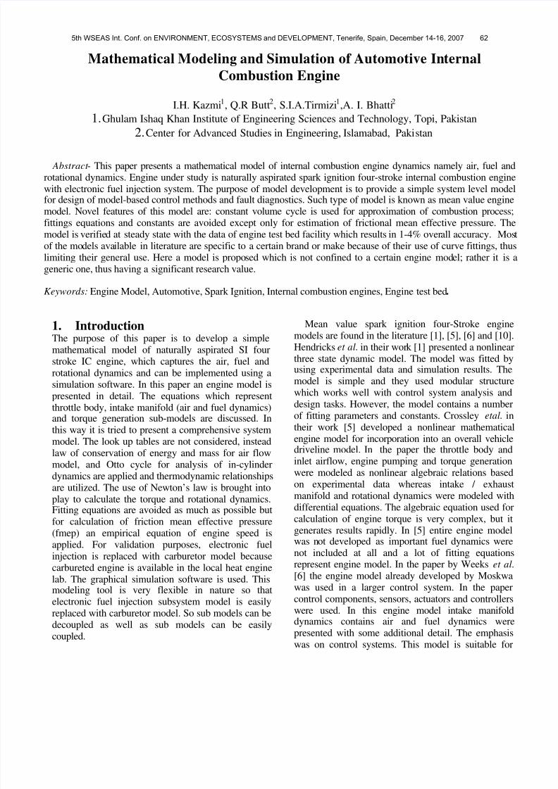
7.3 Torque Generation BlockIn this block indicated torque has been first calculated.
It then subtracts off the friction and pumping torque of the engine to get the brake torque. External load torquewhich to be subtracted if it is, but in this model theexternal load torque has been assumed to be zero
The mean effective pressure has been calculatedfrom the combustion process by using (24). Thistheoretical mean effective pressure is multiplied bythe Otto cycle efficiency to get the indicated meaneffective pressure. Indicated torque is calculated by(27) and pumping torque is evaluated through (28)and friction torque is calculated by (29). Engine speedis found by (31).
8. Simulation ResultsThe simulation results of model of carbureted engineare presented. These results have been verified withthe measured data taken from engine test bed facilityat Faculty of Mechanical engineering (FME) at theGIKI Institute of engineering sciences and technology.The parameters, air mass flow rate, fuel mass flowrate, air-fuel ratio, and torque have been compared.
9. ConclusionMathematical model of internal combustion spark ignition four strokes engine consisting of sub-modelswhich are: throttle body, air dynamics, fuel dynamicsand torque generation models has been presented inthis paper. The model has been implemented ingraphical software as a dynamic continuous system.The simulation results show some of the potential usesof the model. The model may be used in many ways,explained in [6], as nonreal-time engine model, real-time engine model, embedded model, system modeland subsystem model in a larger system. The purpose
of the paper is not to achieve the best possible modelof any specific engine but a mean value engine modelfor design of model-based control methods. Hendricks[1] states that control system design procedures aretolerant of small system modeling errors so anapproximate model is satisfactory for engine controldevelopment application.
1600 1800 2000 2200 2400 2600 2800 3000 3200 3400 3600 380012
14
16
18
20
22
24
Engine Speed (rpm)
B r a k e T o r q u e ( N m )
Engine Model Result
Measured Engine Data
Fig. 3. Brake Torque
TABLE 1ENGINE AIR FUEL RATIOS
TABLE 2Model Air Fuel Ratios
Air-Fuel Ratio
Model MassFlow
Rate of Air
(Kg/sec.)
Model MassFlow Rate of
Fuel (Kg/sec.)
EngineSpeed(rpm)
11.37200.00660510.000580821800
13.23280.00770600.000582342100
15.08370.00880680.000583862400
16.92500.00990760.000585382700
18.74280.01100000.000586893000
20.56420.01210000.000588403300
22.376610.01320000.000589903600
16.8996Average
EngineSpeed
(rpm)
Engine MassFlow Rate of
Air (Kg/sec.)
Engine MassFlow Rate of
Fuel (Kg/sec.)
Air-FuelRatio
1800 0.0084 0.000505 16.6205
2100 0.0094 0.000578 16.2686
2400 0.0108 0.000634 17.0239
2700 0.012 0.00066 18.1845
3000 0.0132 0.000752 17.5625
3300 0.015 0.000792 18.9441
3600 0.0151 0.000792 19.0704
Average 17.6678
5th WSEAS Int. Conf. on ENVIRONMENT, ECOSYSTEMS and DEVELOPMENT, Tenerife, Spain, December 14-16, 2007 67
8/8/2019 Motor Simulink1
http://slidepdf.com/reader/full/motor-simulink1 7/7
TABLE 3ENGINE CALCULATED PARAMETERS
TABLE 4ENGINE MEASURED PARAMETERS
APPENDIX –TEST BED MEASUREMENTS
Test bed type Cussons P8160Test at GIK Institute (FME)Ambient air temperature 298 KAtmospheric pressure 101.325 kPaManometer zero error +3Sp. gravity of manometer fluid 1.88Engine model 243430Manufacturer Briggs & Stratton
Type Four stroke engineCapacity 392 ccMaximum power 7.46 kW at 3600 rpmMaximum torque 22.7 Nm at 2400 rpmAir flow orifice diameter 23 mmDensity of air 1.18 Kg/m
3
Density of petrol 720 Kg/ m3
References
[1] Elbert Hendricks, Spencer C. Sorenson, “ Mean Value Modeling of Spark Ignition Engines,” SAE Technical Paper no.900616, 1990.
[2] Ebert Hendricks, Jim Benjamin Luther, “ Model and Observer Based Control of Internal Combustion Engines,” Proc. MECA (Modeling,Emissions and Control in Automotive engines), Salerno, Italy, 2001.
[3] G. De Nicolao, R. Scattolini and C. Siviero, “ Modeling theVolumetric Efficiency of IC Engines: Parametric, Non-parametricand Neural Techniques,” Control Eng. Practice, Vol. 4, No. 10, pp.1405-1415, 1996.
[4] Per Andersson, Lars Eriksson, Lars Nielsen, “ Modeling and Architecture Examples of Model Based Engine Control,” VehicularSystems, ISY, Linkoping University, SE-581 83 Linkoping,Sweden, 1999
[5] Crossley,P.R.,Cook,J,A.,” A Nonlinear Engine Model for Drive trainSystem Development,” IEEE Int. Conf. ‘Control 91’,ConferencePublication No.332, Vol.2.,Edinburgh,U.K.,March 1991
[6] Weeks,R.W., Moskwa,J.J., ” Automotive Engine Modeling for Real-
Time Control Using MatLab/Simulink,” SAE Technical Paperno.950417,1995
[7] Willard W. Pulkrabek, ” Engineering Fundamentals Of The Internal
Combustion Engine,” Prentice-Hall, Second ed.,2003[8] Eastop,T.D., McConkey,A., “ Applied Thermodynamics For
Engineering Technologists,” 5th ed.,1992[9] Woods, R.L., Lawrence, Kent. L., ” Modeling and Simulation of
Dynamic Systems,” Prentice-Hall, 1997[10] Dobner, Donald J., “A Mathematical Engine Model for
Development of Dynamic Engine Control,” SAE technical paperNo. 800054, 1980
[11] Herbert Goldstein, “Classical Mechanics,” second ed., Addison-Wesley, NY, 1980
Acknowledgment
We are thankful to Heat Engine Lab Mechanical EngineeringDepartment, GIK Institute of Engineering Sciences and
Technology, Topi, for the support of this work.
The authors would also like to thank the HEC, Pakistan for their
financial support.
S.No.Torque(N.m)
Mass FlowRateof Air
(Kg/sec)
Fuel flowrate (gm/sec) Air-Fuel Ratio
1 17.225 0.008359 0.5054 16.53946
2 17.375 0.0094 0.5778 16.23243
3 19.525 0.0108 0.6344 17.01094
4 19.325 0.0120 0.6599 18.25712
5 17.475 0.0132 0.7516 17.51980
6 17.15 0.0150 0.7918 18.94998
7 15.875 0.0151 0.7918 19.05858
S.No.EngineSpeed
(rpm)Force (N)
Time for30ml fuel
(sec.)
ManometerCorrected
Height(mm)
1 1800 68.9 42.74 13.50
2 2100 69.5 37.38 17.00
3 2400 78.1 34.05 22.50
4 2700 77.3 32.73 28.05
5 3000 69.9 28.74 33.50
6 3300 68.6 27.28 43.50
7 3600 63.5 27.28 44.00
5th WSEAS Int. Conf. on ENVIRONMENT, ECOSYSTEMS and DEVELOPMENT, Tenerife, Spain, December 14-16, 2007 68
![SELECTION GUIDE 2007 - kdhyd.com CATALOGUE.pdf · MS wheel motor MG motor MK motor MD motor ES axle ML motor MZ motor MF motor ... Max.pressure bar [PSI] 450 [6 350] 400 [5 800] [6](https://img.dokumen.tips/doc/110x75/5babf46109d3f2ca018cf468/selection-guide-2007-kdhyd-cataloguepdf-ms-wheel-motor-mg-motor-mk-motor.jpg)


![AC/DC Geared Motor and Gearhead - raveo.czkatalog]_DKM_A... · DKM Products Overview Induction Motor 2 Pole Motor Reversible Motor E.M. Brake Motor Clutch & Brake Motor Torque Motor](https://img.dokumen.tips/doc/110x75/5ca5afa988c9930a6e8c9362/acdc-geared-motor-and-gearhead-raveocz-katalogdkma-dkm-products-overview.jpg)