Embed Size (px)
Citation preview
Motion Planning for Robotic Manipulation ofDeformable Linear Objects
Mitul Saha�����
, Pekka Isto�����
, and Jean-Claude Latombe�
(1) Artificial Intelligence Lab, Stanford University, Stanford, CA, USA. (email: � mitul,latombe @cs.stanford.edu)(2) Computer Science Department, University of Vassa, Finland. (email: [email protected])
Abstract— Research on robotic manipulation has mainlyfocused on manipulating rigid objects so far. However, manyimportant application domains require manipulating deformableobjects, especially deformable linear objects (DLOs), such asropes, cables, and sutures. Such objects are far more challengingto handle, as they can exhibit a much greater diversity ofbehaviors. This paper describes a new motion planner formanipulating DLOs and tying knots (self-knots and knotsaround simple static objects) using cooperating robot arms. Theplanner constructs a topologically-biased probabilistic roadmapin the DLO’s configuration space. Unlike in traditional motionplanning problems, the goal is a topological state of the world,rather than a geometric one. The implemented planner wastested in simulation to achieve various knots like bowline,neck-tie, bow (shoe-lace), and stun-sail. In real-life, the plannerwas used to tie bowline knots with various household ropes ona hardware platform with two PUMA 560 robots.
Index Terms—Manipulation planning, deformable objects, knottying, probabilistic roadmaps
I. INTRODUCTION
Robotic manipulation of rigid objects is a rather well-studied problem. Here, we focus on manipulating deformablelinear objects (DLOs), such as ropes, cables, and sutures.Progress in robotic manipulation of DLOs can benefit manyapplication domains, like manufacturing (loading cable har-nesses and robot dresses), medical surgery (especially sutur-ing), and agriculture, where DLOs are ubiquitous. It can alsobenefit service-based humanoid robots, since tying knots is acommon activity in daily life. However, DLOs add a numberof difficulties to the manipulation task. They exhibit a muchgreater diversity of behaviors than rigid objects, by takingmany different shapes when submitted to external forces. Inparticular, self-collisions are possible and must be considered.Furthermore, the manipulation of DLOs almost inevitablyrequires two, or more, arms performing well-coordinated mo-tions and re-grasp operations. Finally, the topology of the goalstate of a DLO is usually far more important than its exactshape.
In this paper we describe a new motion planner for ma-nipulating DLOs with two cooperating robot arms. Figure 1shows two typical problems. In Figure 1(a), a segment of ropeis initially unwound. Figures 1(b) (c) depict two types ofgoal states in which the rope forms a self-knot (bowline) andwinds around some static objects, respectively. Our plannerdoes not depend on any particular physical model of the DLO.Instead, it takes a model as input, in the form of a state-
Fig. 1. Initial (a) and goal (b)-(c) states in a manipulation problem
transition function. Using this function and the model of therobot arms, the planner constructs a probabilistic roadmap inthe configuration space of the DLO. The sampling of thisroadmap is biased toward achieving the topology of the goalstate of the DLO. During roadmap construction, the plannertests that the grasp points on the rope are accessible by thearms without collision. The planner assumes that simple staticsliding supports (independent of the robot arms), which wecall needles (by analogy to the needles used in knitting)are available and can be used when needed, to maintain theintegrity of certain portions of the DLO during manipulation.A novel method is used to account for the interaction ofthe DLO with simple rigid objects. Curve representations ofthe objects, obtained from their skeletonization, are “chained”with the DLO to produce a ���� ������������ semi-deformable linearobject (sDLO). Thereafter, the problem reduces to that oftying self-knots with the composite sDLO. We implementedthe planner and tested it in simulation and real-life. Wedemonstrated its effectiveness by tying commonly used knotslike bowline, neck-tie, bow (shoe-lace), and stun-sail.
II. RELATION TO PREVIOUS WORK
A. Manipulation Planning
Robot manipulation planning with rigid objects was firstaddressed in [22]. The randomized algorithm proposed in [10]generates motion paths for multiple cooperating manipulatorsto manipulate a movable rigid object. The algorithm assumesthat a set of discrete grasps is given as input. The algorithmproposed in [19] works with continuous sets of grasps of rigidobjects but plans for a single manipulator. The re-grasp isdone by releasing the object. In the case of a DLO, releasingthe grasp makes the DLO very unstable due to its deformingnature. An algorithm for planning paths for elastic objects,especially for flexible plates and cables, is presented in [8].
Fig. 2. Representation of a DLO
This algoritm plans motions only for the object, not forthe manipulator. The problem of path planning for DLOs inpresence of obstacles is addressed as a variational problemin [20]. Their formulation does not consider the manipulatoreither. All these works focus on geometric planning whilewe focus on topological planning, because while manipulatingDLOs, especially to tie knots, it is more important to achievean acceptable topology than a specific geometry.
B. Application of Knot Theory in Robotics
Knot theory provides means to capture and analyse thetopological states and state transitions of a DLO [1]. Itsapplications in robotics include work presented in [12]. Likeus, they present a data structure for describing the state of aDLO as a sequence of signed crossings. State transitions arecaused by Reidemeister moves and a crossing operation thatmoves the end of the DLO over another part to make a newcrossing. Similar ideas are being used in [21] to build a visionguided robot system for one-handed manipulation of a DLOwith the aid of the floor. However, collision constraints andthe physical behavior of the DLO are not considered duringthe planning phase. In [7], motion planning techniques fromrobotics are used to untangle mathematical knots.
C. Vision-Based DLO Manipulation
The difficulty of accurately modeling deformable objectshas motivated vision-based approaches to DLO manipulation.Among other examples, in [11], methods for DLO modeling,recognition, and parameter identification are presented, whichhave been embedded in a system capable of tying a ropearound a cylinder with two manipulators. In [15], a sensing-based method is proposed for picking up hanging DLOs. Inour work, we do not rely on the availablity of any sensingsystem to guide the manipulation in real-time. Instead, wefocus on precomputing manipulation plans which are robustto uncertainties in the physical model of the DLO.
III. MODELING A DEFORMABLE LINEAR OBJECT
A. Geometric Model
We describe the geometry of a DLO by a curved cylinder oflength � and circular cross-section of constant non-zero radius(see Figure 2). The ������� of this cylinder is a smooth curve �parameterized by the Euclidean length � along the DLO, i.e.:
� �!�#"%$ &('��*),+-��./��01"3254�'where ��.6&�0 is the ������7 of the DLO and ��.6�10 its 8����:9 . Wheneverthe physical model of the DLO includes torsion or twist,we also attach a Cartesian coordinate frame ;<.���0 with eachpoint ��./�=0 as shown in Figure 2. We call >@?A.6��'�;B0 a����CED,�/F�G,HI�!�J�J��C of the DLO.
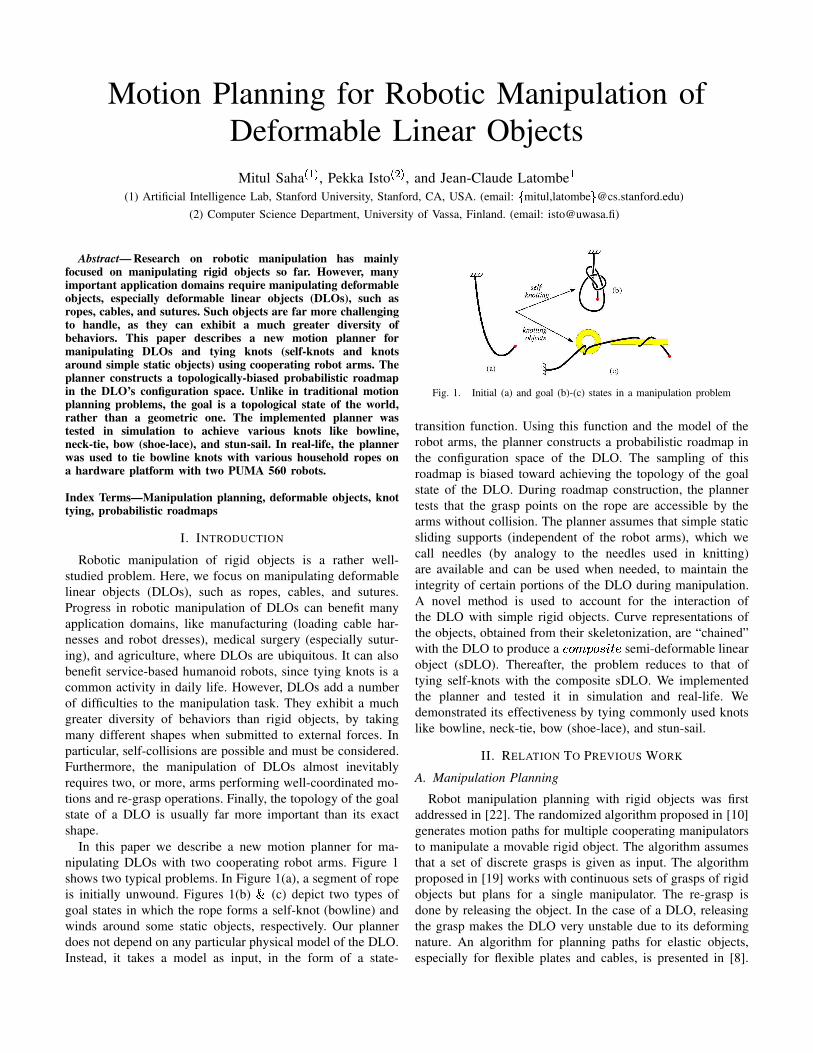
(a) (b)Fig. 3. (a): The crossings in the “figure-8” knot. (b): The sign conventionfor the crossings
B. Physical Model
Designated points located at ��KI'MLNLOLN'P��Q on the DLO areF:H��R��� points. These are the only points whose positions ��.��IS�0and orientations ;<./�=S�0T'��U?WV!'MLNLOLN'PX , can be directly controlledby the robotic manipulation system.
The physical model of a DLO is given in the form of a���������Y�JHI��CE���/�J�J��C function D that maps both a configuration>�Z\[O] of the DLO and a X -vector G of small displacements ofthe grasp points (the control input) to a new configuration>M^!_J` . We assume that both >=Z\[O] and >�^a_J` are stable configu-rations, although the DLO may exhibit dynamic behavior (e.g.,snapping) during the transition from >�Z\[O] to >�^a_J` . We do notconsider elapsed time between >�Z\[O] and >�^a_J` , although it couldbe easily added to the model.
We assume that the model in D handles collisions withobstacles, as well as self-collisions, so that the DLO doesnot “jump” over itself or obstacles. In addition, if G wouldcause violations of physical constraints associated with theDLO, e.g., over-stretching, then the function D indicates thatthe execution of G is impossible. As we do not allow the robotarms to touch the DLO at points other than the grasp points,D reports failure if it detects a collision between the DLO andan arm.
Several physical models of DLOs proposed in the literature(e.g., [2], [5], [13], [14], [23]) are relevant to the constructionof D .
C. Topological Model
We characterize the topology of the DLO at some configu-ration >b?c.6��'�;B0 by means of its crossing configuration [1].A crossing configuration is defined with respect to a referenceplane d . Let �Me be the projection of � into d . The crossingconfiguration of � with respect to d is defined only when nomore than two points in � project to the same point in d .Morever, for any two points � and f in � that projects to thesame point � e ?Wf e in d , � e must admit two distinct tangentsat � e ?gf e , which are the respective projections of the tangentsto � at � and f . Then a �THI���=����ChFji in d is any point on � ethat is the projection of two distinct points of � .
Let ��.��IK�0 and �a.��=k�0 , with �IKjlc�=k , be the two points on� that projects to the crossing i in d . Let mIK and mMk be theprojections of the tangent to � at ��./��K�0 and ��./�=k=0 , respectively.The status of i is said to be ��n:��H if �a.�� K 0 lies above ��./� k 0 withrespect to d , otherwise it is G�Co9��=H . Moreover, i is assigned asign. This sign is + if (1) i is over and the counter-clockwiseangle between m K and m k is less that p , or (2) i is under andthe clockwise angle between m K and m k is less than p . Thesign of i is - in all other cases. The sign convention is alsodepicted in Figure 3(b).
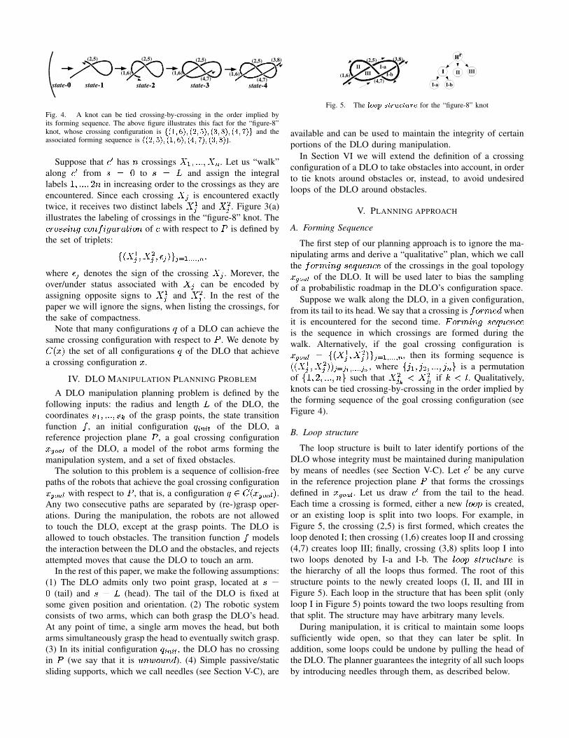
Fig. 4. A knot can be tied crossing-by-crossing in the order implied byits forming sequence. The above figure illustrates this fact for the “figure-8”knot, whose crossing configuration is q ���Tr�s��Jr\���=r/t���r��Nu=r�v���r\�Nw�r�xT�/y and theassociated forming sequence is
�6���=r/t��Jr\�6�Tr�s���r��Ow�r�xT��r\��u=r/v����.
Suppose that � e has C crossings iYKI'MLNLOLN'\iz^ . Let us “walk”along � e from �{?|& to �{?|� and assign the integrallabels V!'MLNLOLN'P}�C in increasing order to the crossings as they areencountered. Since each crossing ib~ is encountered exactlytwice, it receives two distinct labels i K~ and i k~ . Figure 3(a)illustrates the labeling of crossings in the “figure-8” knot. The�THI���=����ChFz����CED,�/F�G,HI�!�J�J��C of � with respect to d is defined bythe set of triplets: �
.�i K~ '�i k~ 'P��~=0T��~���KT��������� ^,Lwhere �\~ denotes the sign of the crossing i�~ . Morever, theover/under status associated with i�~ can be encoded byassigning opposite signs to i K~ and i k~ . In the rest of thepaper we will ignore the signs, when listing the crossings, forthe sake of compactness.
Note that many configurations > of a DLO can achieve thesame crossing configuration with respect to d . We denote by� .��,0 the set of all configurations > of the DLO that achievea crossing configuration � .
IV. DLO MANIPULATION PLANNING PROBLEM
A DLO manipulation planning problem is defined by thefollowing inputs: the radius and length � of the DLO, thecoordinates ��KI'�LOLNLO'���Q of the grasp points, the state transitionfunction D , an initial configuration >=SN^�SO� of the DLO, areference projection plane d , a goal crossing configuration����Z��T[ of the DLO, a model of the robot arms forming themanipulation system, and a set of fixed obstacles.
The solution to this problem is a sequence of collision-freepaths of the robots that achieve the goal crossing configuration� ��Z��T[ with respect to d , that is, a configuration >B" � .�� ��ZP��[ 0 .Any two consecutive paths are separated by (re-)grasp oper-ations. During the manipulation, the robots are not allowedto touch the DLO, except at the grasp points. The DLO isallowed to touch obstacles. The transition function D modelsthe interaction between the DLO and the obstacles, and rejectsattempted moves that cause the DLO to touch an arm.
In the rest of this paper, we make the following assumptions:(1) The DLO admits only two point grasp, located at ��?& (tail) and ��?�� (head). The tail of the DLO is fixed atsome given position and orientation. (2) The robotic systemconsists of two arms, which can both grasp the DLO’s head.At any point of time, a single arm moves the head, but botharms simultaneously grasp the head to eventually switch grasp.(3) In its initial configuration > SO^�SO� , the DLO has no crossingin d (we say that it is G,C�����G�Co9 ). (4) Simple passive/staticsliding supports, which we call needles (see Section V-C), are
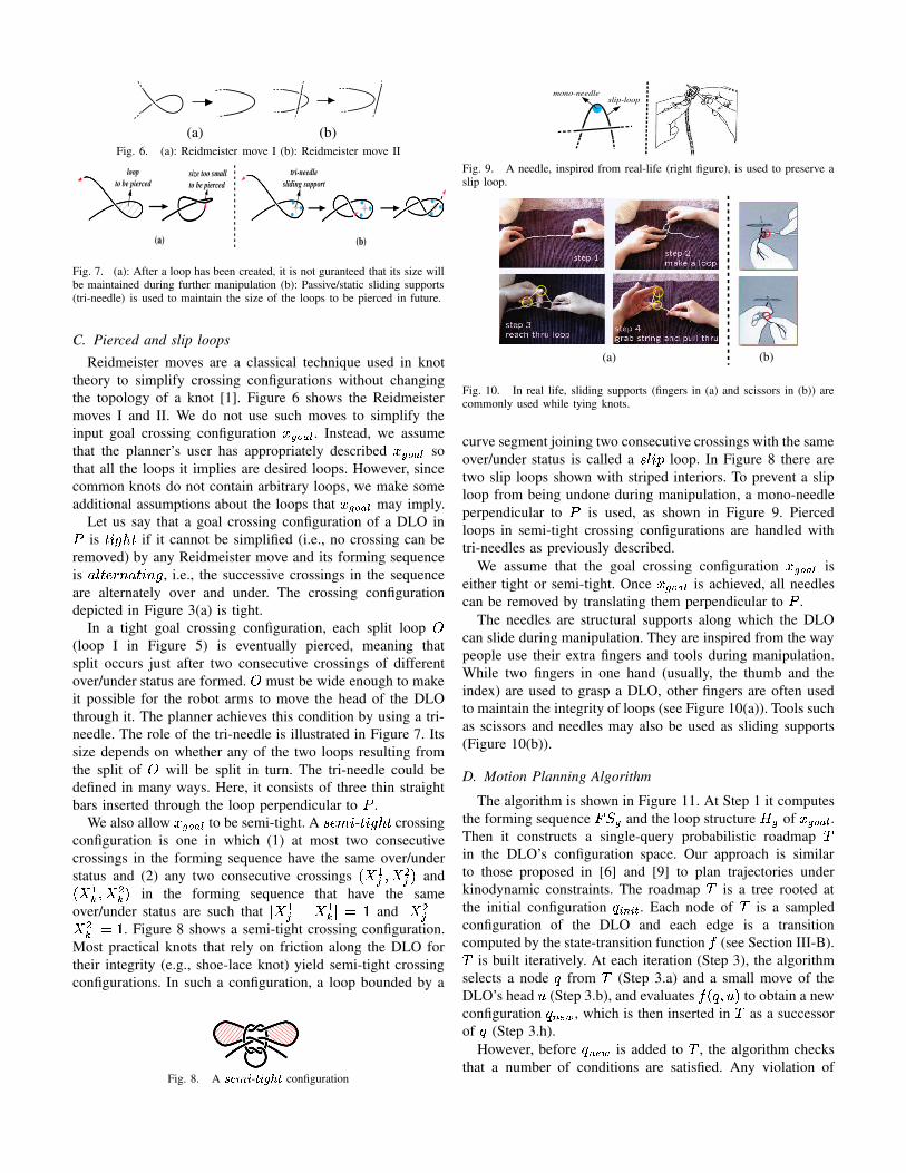
Fig. 5. The �������#�������a�J���a��� for the “figure-8” knot
available and can be used to maintain the integrity of certainportions of the DLO during manipulation.
In Section VI we will extend the definition of a crossingconfiguration of a DLO to take obstacles into account, in orderto tie knots around obstacles or, instead, to avoid undesiredloops of the DLO around obstacles.
V. PLANNING APPROACH
A. Forming Sequence
The first step of our planning approach is to ignore the ma-nipulating arms and derive a “qualitative” plan, which we callthe Dh��H� 5��ChF5�=��>�G,�=Co��� of the crossings in the goal topology� ��ZP��[ of the DLO. It will be used later to bias the samplingof a probabilistic roadmap in the DLO’s configuration space.
Suppose we walk along the DLO, in a given configuration,from its tail to its head. We say that a crossing is Dh��H� 3��9 whenit is encountered for the second time. �#��H� 3�/ChF��=��>�G,�=Co���is the sequence in which crossings are formed during thewalk. Alternatively, if the goal crossing configuration is����ZP��[�?
�.6i K~ '\i k~ 0��M~���KT��������� ^ , then its forming sequence is.\.6i K~ '�i k~ 0�0/~��,~\ M��������� ~�¡ , where
��¢K�'¢ka'MLNLOLN'
¢^,� is a permutation
of
�Va'�}R'MLNLNLO'�CU� such that i k~J£ l¤i k~J¥ if X¦l§7 . Qualitatively,
knots can be tied crossing-by-crossing in the order implied bythe forming sequence of the goal crossing configuration (seeFigure 4).
B. Loop structure
The loop structure is built to later identify portions of theDLO whose integrity must be maintained during manipulationby means of needles (see Section V-C). Let ��e be any curvein the reference projection plane d that forms the crossingsdefined in � �TZP��[ . Let us draw � e from the tail to the head.Each time a crossing is formed, either a new 76�I��� is created,or an existing loop is split into two loops. For example, inFigure 5, the crossing (2,5) is first formed, which creates theloop denoted I; then crossing (1,6) creates loop II and crossing(4,7) creates loop III; finally, crossing (3,8) splits loop I intotwo loops denoted by I-a and I-b. The 76�I���¤���JH�G,�T�JG,HI� isthe hierarchy of all the loops thus formed. The root of thisstructure points to the newly created loops (I, II, and III inFigure 5). Each loop in the structure that has been split (onlyloop I in Figure 5) points toward the two loops resulting fromthat split. The structure may have arbitrary many levels.
During manipulation, it is critical to maintain some loopssufficiently wide open, so that they can later be split. Inaddition, some loops could be undone by pulling the head ofthe DLO. The planner guarantees the integrity of all such loopsby introducing needles through them, as described below.
(a) (b)Fig. 6. (a): Reidmeister move I (b): Reidmeister move II
Fig. 7. (a): After a loop has been created, it is not guranteed that its size willbe maintained during further manipulation (b): Passive/static sliding supports(tri-needle) is used to maintain the size of the loops to be pierced in future.
C. Pierced and slip loops
Reidmeister moves are a classical technique used in knottheory to simplify crossing configurations without changingthe topology of a knot [1]. Figure 6 shows the Reidmeistermoves I and II. We do not use such moves to simplify theinput goal crossing configuration �,��ZP��[ . Instead, we assumethat the planner’s user has appropriately described �h��Z���[ sothat all the loops it implies are desired loops. However, sincecommon knots do not contain arbitrary loops, we make someadditional assumptions about the loops that �,��ZP��[ may imply.
Let us say that a goal crossing configuration of a DLO ind is �J��F(8�� if it cannot be simplified (i.e., no crossing can beremoved) by any Reidmeister move and its forming sequenceis �:7����=H�Co�!�J��ChF , i.e., the successive crossings in the sequenceare alternately over and under. The crossing configurationdepicted in Figure 3(a) is tight.
In a tight goal crossing configuration, each split loop ¨(loop I in Figure 5) is eventually pierced, meaning thatsplit occurs just after two consecutive crossings of differentover/under status are formed. ¨ must be wide enough to makeit possible for the robot arms to move the head of the DLOthrough it. The planner achieves this condition by using a tri-needle. The role of the tri-needle is illustrated in Figure 7. Itssize depends on whether any of the two loops resulting fromthe split of ¨ will be split in turn. The tri-needle could bedefined in many ways. Here, it consists of three thin straightbars inserted through the loop perpendicular to d .
We also allow ����Z��T[ to be semi-tight. A ���= 3� - �J�/F(8(� crossingconfiguration is one in which (1) at most two consecutivecrossings in the forming sequence have the same over/understatus and (2) any two consecutive crossings .�i K~ '�i k~ 0 and.�i KQ '\i kQ 0 in the forming sequence that have the sameover/under status are such that © i K~«ª i KQ ©*?-V and © i k~«ªi kQ ©a?¬V . Figure 8 shows a semi-tight crossing configuration.Most practical knots that rely on friction along the DLO fortheir integrity (e.g., shoe-lace knot) yield semi-tight crossingconfigurations. In such a configuration, a loop bounded by a
Fig. 8. A ���\¯® - ��®�°M±I� configuration
Fig. 9. A needle, inspired from real-life (right figure), is used to preserve aslip loop.
Fig. 10. In real life, sliding supports (fingers in (a) and scissors in (b)) arecommonly used while tying knots.
curve segment joining two consecutive crossings with the sameover/under status is called a ��76��� loop. In Figure 8 there aretwo slip loops shown with striped interiors. To prevent a sliploop from being undone during manipulation, a mono-needleperpendicular to d is used, as shown in Figure 9. Piercedloops in semi-tight crossing configurations are handled withtri-needles as previously described.
We assume that the goal crossing configuration � ��Z��T[ iseither tight or semi-tight. Once � ��ZP��[ is achieved, all needlescan be removed by translating them perpendicular to d .
The needles are structural supports along which the DLOcan slide during manipulation. They are inspired from the waypeople use their extra fingers and tools during manipulation.While two fingers in one hand (usually, the thumb and theindex) are used to grasp a DLO, other fingers are often usedto maintain the integrity of loops (see Figure 10(a)). Tools suchas scissors and needles may also be used as sliding supports(Figure 10(b)).
D. Motion Planning Algorithm
The algorithm is shown in Figure 11. At Step 1 it computesthe forming sequence �³² � and the loop structure ´ � of � ��ZP��[ .Then it constructs a single-query probabilistic roadmap µin the DLO’s configuration space. Our approach is similarto those proposed in [6] and [9] to plan trajectories underkinodynamic constraints. The roadmap µ is a tree rooted atthe initial configuration >�SN^�SO� . Each node of µ is a sampledconfiguration of the DLO and each edge is a transitioncomputed by the state-transition function D (see Section III-B).µ is built iteratively. At each iteration (Step 3), the algorithmselects a node > from µ (Step 3.a) and a small move of theDLO’s head G (Step 3.b), and evaluates DU.�>:'\G�0 to obtain a newconfiguration >�^a_J` , which is then inserted in µ as a successorof > (Step 3.h).
However, before >=^a_J` is added to µ , the algorithm checksthat a number of conditions are satisfied. Any violation of
Algorithm TWO-ARM-KNOTTER ( >�SN^�S�� , ����Z���[ , d )1. �³² �<¶ Forming-Seq( � ��Z��T[ ), ´ �<¶ Loop-Struct( �³² � )2. µ .Insert(NULL, > SN^�S�� )3. Loop ·W��� times
a. Pick > from µ with a probability measure biasedtowards � ��ZP��[
b. Pick control vector G at randomc. >M^!_J` ¶ DU.�>:'\G�0d. Return to Step 3 if:
- D returned that the move was impossible, or- the forming sequence of >=^a_J` is not a
sub-sequence of �³²��f. Inspect ´b� and add needles if neededg. Return to Step 3 if the arms cannot perform Gh. µ .Insert( > , >�^a_J` )i. If > ^a_J` " � .�� ��Z���[ 0 , then exit with manipulation path
4. Exit with Dh���J7�G,HI�Fig. 11. The DLO manipulation planning algorithm
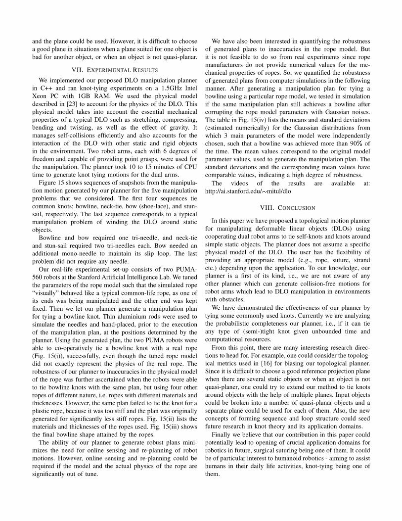
Fig. 12. Suppose a split loop is created when the crossings ¸ followed by¹are formed. A tri-needle is placed, just after ¸ is formed, along the DLO
in the region infered by matching the crossings associated with the currentconfiguration of the DLO and the crossings in º�»�¼�½T¾ which define the loop.
these conditions leads to start a new iteration at Step 3.First, DU.6>:'\G�0 must have indicated that the control vector Gis possible (see Section III-B). If this is the case, the planningalgorithm verifies that the forming sequence at >�^a_J` is asubsequence of �³²�� beginning at the same crossing as �³²��(this causes the topological biasing of µ ). If yes, it checkswhether new needles are needed and adds them (they thenbecome obstacles). Needles are placed when a slip or splitloop is about to be formed, as indicated by ´ � . They areplaced along the DLO where the loop is expected to be formed(see Figure 12). However, the planner does not plan for themanipulation of the needles. It can be done with the helpof additional manipulators and some movable fixtures for theneedles. Throughout the planning, the crossing configurationof �,^a_J` is determined with respect to d . Next, the plannerchecks that the robot arm currently grasping the head ofthe DLO can track the motion of the DLO’s head withoutcolliding (using the arm’s IK). If not, it checks whether theother arm can perform the motion instead, after a grasp switchbetween the two arms at > . The collision free motion of thearms for performing a grasp switch can be computed usingany single-query probabilistic-roadmap planner [3]. In ourimplementation, we use the SBL planner [17]. The motionof the arms and the needle placements are stored along with>M^a_J` in µ .
The planner succeeds when it achieves a configuration>M^a_J`¿" � .�����ZP��[/0 , which occurs when the number of crossings
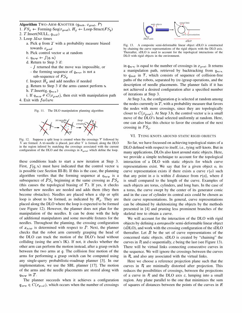
Fig. 13. A composite semi-deformable linear object sDLO is constructedby chaining the curve representations of the rigid objects with the DLO axis.Thereafter, sDLO is used to account for the topological interactions of theDLO with rigid objects in the environment.
in >M^a_J` is equal to the number of crossings in �h�TZP��[ . It returnsa manipulation path, retrieved by backtracking from >�^a_�`to >�SO^�SO� in µ , which consists of sequence of collision-freepaths of the robots, separated by (re-)grasp operations, and thedescription of needle placements. The planner fails if it hasnot achieved a desired configuration after a specified numberof iterations at Step 3.
At Step 3.a, the configuration > is selected at random amongthe nodes currently in µ , with a probability measure that favorsthe nodes with more crossings, since they are topologicallycloser to
� .�����Z���[�0 . At Step 3.b, the control vector G is a smallmove of the DLO’s head selected uniformly at random. Here,one can also bias this choice to favor the creation of the nextcrossing in �³² � .
VI. TYING KNOTS AROUND STATIC RIGID OBJECTS
So far, we have focussed on achieving topological states of aDLO defined with respect to itself, i.e., tying self-knots. But inmany applications, DLOs also knot around static objects. Here,we provide a simple technique to account for the topologicalinteraction of a DLO with static objects for which curverepresentations exist. We say that for a given object � , itscurve representation exists if there exists a curve H:.���0 suchthat any point in � is within À distance from HR.6��0 , where Àis small compared to the length of the curve. Examples ofsuch objects are torus, cylinders, and long bars. In the case ofa torus, the curve swept by the center of its generator conicand in the case of cylinder its central axis could be chosen astheir curve representations. In general, curve representationscan be obtained by skeletonizing the objects by the methodspresented in [4] and pruning less prominent branches of theskeletal tree to obtain a curve.
We will account for the interaction of the DLO with rigidobjects by defining a ���� ������������ semi-deformable linear object(sDLO), and work with the crossing configuration of the sDLOthereafter. Let Á be the set of curve representations of theconcerned static objects. sDLO is created by “chaining” thecurves in Á and � sequentially, � being the last (see Figure 13).There will be virtual links connecting consecutive curves inthe sequence. We will ignore the crossings between the curvesin Á , and also any associated with the virtual links.
Here we choose a reference projection plane such that thecurves in Á are minimally distorted after projection. Thisreduces the possibilities of crossings, between the projectionsof a curve in Á and the DLO axis � , lumping into a smallregion. Any plane parallel to the one that minimizes the sumof squares of distances between the points of the curves in Á
and the plane could be used. However, it is difficult to choosea good plane in situations when a plane suited for one object isbad for another object, or when an object is not quasi-planar.
VII. EXPERIMENTAL RESULTS
We implemented our proposed DLO manipulation plannerin C++ and ran knot-tying experiments on a 1.5GHz IntelXeon PC with 1GB RAM. We used the physical modeldescribed in [23] to account for the physics of the DLO. Thisphysical model takes into account the essential mechanicalproperties of a typical DLO such as stretching, compressing,bending and twisting, as well as the effect of gravity. Itmanages self-collisions efficiently and also accounts for theinteraction of the DLO with other static and rigid objectsin the environment. Two robot arms, each with 6 degrees offreedom and capable of providing point grasps, were used forthe manipulation. The planner took 10 to 15 minutes of CPUtime to generate knot tying motions for the dual arms.
Figure 15 shows sequences of snapshots from the manipula-tion motion generated by our planner for the five manipulationproblems that we considered. The first four sequences tiecommon knots: bowline, neck-tie, bow (shoe-lace), and stun-sail, respectively. The last sequence corresponds to a typicalmanipulation problem of winding the DLO around staticobjects.
Bowline and bow required one tri-needle, and neck-tieand stun-sail required two tri-needles each. Bow needed anadditional mono-needle to maintain its slip loop. The lastproblem did not require any needle.
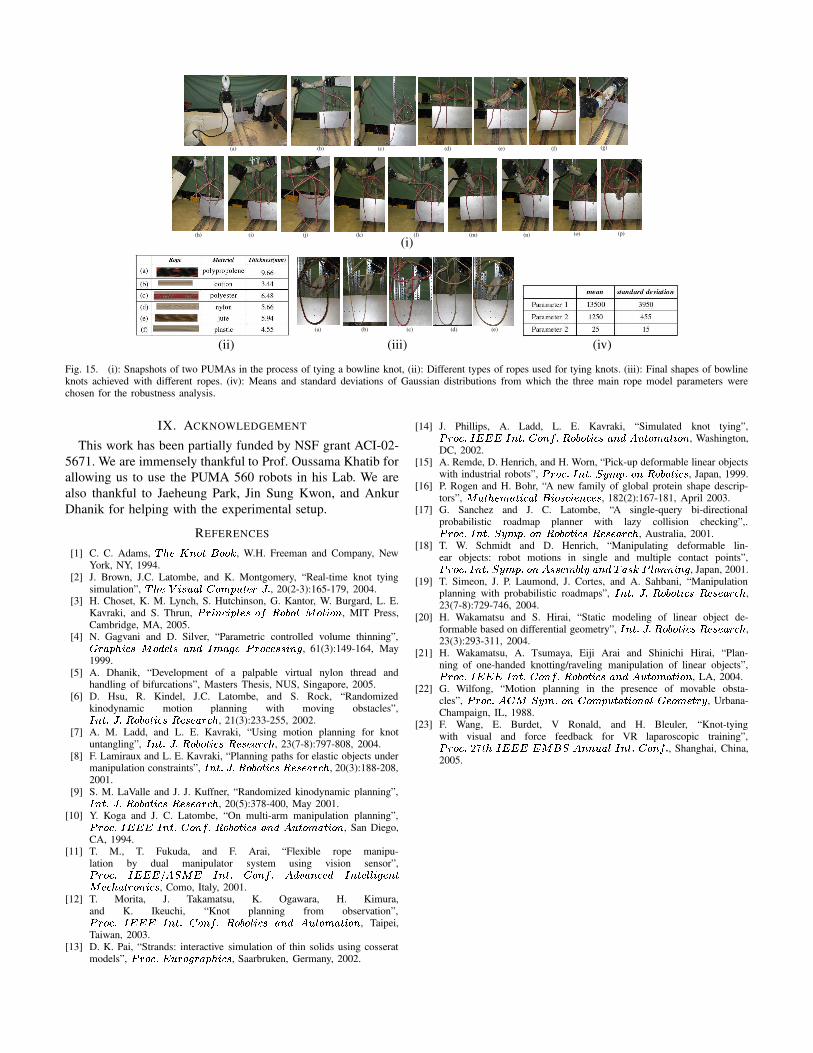
Our real-life experimental set-up consists of two PUMA-560 robots at the Stanford Artificial Intelligence Lab. We tunedthe parameters of the rope model such that the simulated rope“visually” behaved like a typical common-life rope, as one ofits ends was being manipulated and the other end was keptfixed. Then we let our planner generate a manipulation planfor tying a bowline knot. Thin aluminium rods were used tosimulate the needles and hand-placed, prior to the executionof the manipulation plan, at the positions determined by theplanner. Using the generated plan, the two PUMA robots wereable to co-operatively tie a bowline knot with a real rope(Fig. 15(i)), successfully, even though the tuned rope modeldid not exactly represent the physics of the real rope. Therobustness of our planner to inaccuracies in the physical modelof the rope was further ascertained when the robots were ableto tie bowline knots with the same plan, but using four otherropes of different nature, i.e. ropes with different materials andthicknesses. However, the same plan failed to tie the knot for aplastic rope, because it was too stiff and the plan was originallygenerated for significantly less stiff ropes. Fig. 15(ii) lists thematerials and thicknesses of the ropes used. Fig. 15(iii) showsthe final bowline shape attained by the ropes.
The ability of our planner to generate robust plans mini-mizes the need for online sensing and re-planning of robotmotions. However, online sensing and re-planning could berequired if the model and the actual physics of the rope aresignificantly out of tune.
We have also been interested in quantifying the robustnessof generated plans to inaccuracies in the rope model. Butit is not feasible to do so from real experiments since ropemanufacturers do not provide numerical values for the me-chanical properties of ropes. So, we quantified the robustnessof generated plans from computer simulations in the followingmanner. After generating a manipulation plan for tying abowline using a particular rope model, we tested in simulationif the same manipulation plan still achieves a bowline aftercorrupting the rope model parameters with Gaussian noises.The table in Fig. 15(iv) lists the means and standard deviations(estimated numerically) for the Gaussian distributions fromwhich 3 main parameters of the model were independentlychosen, such that a bowline was achieved more than 90 Â ofthe time. The mean values correspond to the original modelparameter values, used to generate the manipulation plan. Thestandard deviations and the corresponding mean values havecomparable values, indicating a high degree of robustness.
The videos of the results are available at:http://ai.stanford.edu/ Ã mitul/dlo
VIII. CONCLUSION
In this paper we have proposed a topological motion plannerfor manipulating deformable linear objects (DLOs) usingcooperating dual robot arms to tie self-knots and knots aroundsimple static objects. The planner does not assume a specificphysical model of the DLO. The user has the flexibility ofproviding an appropriate model (e.g., rope, suture, strandetc.) depending upon the application. To our knowledge, ourplanner is a first of its kind, i.e., we are not aware of anyother planner which can generate collision-free motions forrobot arms which lead to DLO manipulation in environmentswith obstacles.
We have demonstrated the effectiveness of our planner bytying some commonly used knots. Currently we are analyzingthe probabilistic completeness our planner, i.e., if it can tieany type of (semi-)tight knot given unbounded time andcomputational resources.
From this point, there are many interesting research direc-tions to head for. For example, one could consider the topolog-ical metrics used in [16] for biasing our topological planner.Since it is difficult to choose a good reference projection planewhen there are several static objects or when an object is notquasi-planer, one could try to extend our method to tie knotsaround objects with the help of multiple planes. Input objectscould be broken into a number of quasi-planar objects and aseparate plane could be used for each of them. Also, the newconcepts of forming sequence and loop structure could seedfuture research in knot theory and its application domains.
Finally we believe that our contribution in this paper couldpotentially lead to opening of crucial application domains forrobotics in future, surgical suturing being one of them. It couldbe of particular interest to humanoid robotics - aiming to assisthumans in their daily life activities, knot-tying being one ofthem.
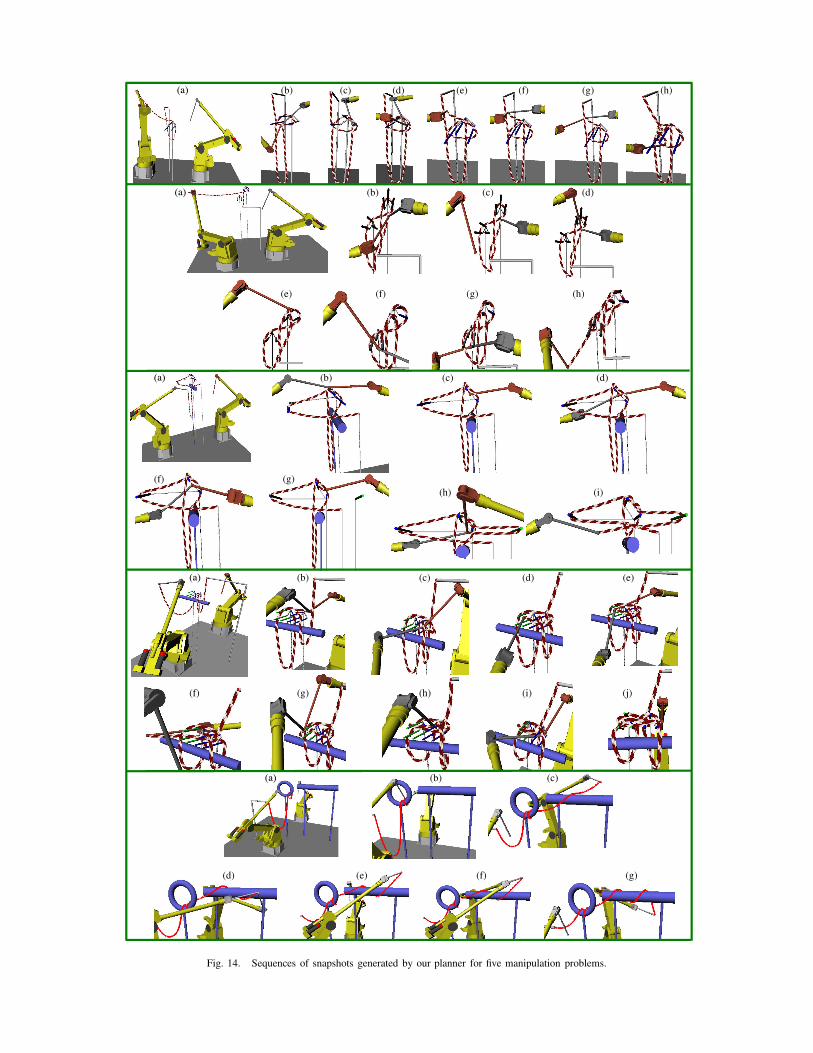
Fig. 14. Sequences of snapshots generated by our planner for five manipulation problems.
(i)
(ii) (iii) (iv)
Fig. 15. (i): Snapshots of two PUMAs in the process of tying a bowline knot, (ii): Different types of ropes used for tying knots. (iii): Final shapes of bowlineknots achieved with different ropes. (iv): Means and standard deviations of Gaussian distributions from which the three main rope model parameters werechosen for the robustness analysis.
IX. ACKNOWLEDGEMENT
This work has been partially funded by NSF grant ACI-02-5671. We are immensely thankful to Prof. Oussama Khatib forallowing us to use the PUMA 560 robots in his Lab. We arealso thankful to Jaeheung Park, Jin Sung Kwon, and AnkurDhanik for helping with the experimental setup.
REFERENCES
[1] C. C. Adams, Ä�±��ÆÅ Ç:�P�UÈÉ����Ê , W.H. Freeman and Company, NewYork, NY, 1994.
[2] J. Brown, J.C. Latombe, and K. Montgomery, “Real-time knot tyingsimulation”, Ä�±��ÌËU®��\�aÍM�(ÎU�P1�I�������ÐÏ�Ñ , 20(2-3):165-179, 2004.
[3] H. Choset, K. M. Lynch, S. Hutchinson, G. Kantor, W. Burgard, L. E.Kavraki, and S. Thrun, ÒU��®�Ç���® �a�����Ó��ÔYÕE��ÖJ�P�Ø׫�P��®���Ç , MIT Press,Cambridge, MA, 2005.
[4] N. Gagvani and D. Silver, “Parametric controlled volume thinning”,Ù �TÍ\��±�®����³×«��Ú����N�#Í�Ç:Ú<ÛT Í�°M��ÒU�T�����P�P�\®NÇ�° , 61(3):149-164, May1999.
[5] A. Dhanik, “Development of a palpable virtual nylon thread andhandling of bifurcations”, Masters Thesis, NUS, Singapore, 2005.
[6] D. Hsu, R. Kindel, J.C. Latombe, and S. Rock, “Randomizedkinodynamic motion planning with moving obstacles”,ÛTÇ���Ñ�Ï�ÑIÕ���ÖJ�P��®����ÌÕ��P����ÍM�T��± , 21(3):233-255, 2002.
[7] A. M. Ladd, and L. E. Kavraki, “Using motion planning for knotuntangling”, ÛTÇ���ÑaÏ=Ñ�Õ���ÖJ�P��®����ÌÕ��P����ÍM�T��± , 23(7-8):797-808, 2004.
[8] F. Lamiraux and L. E. Kavraki, “Planning paths for elastic objects undermanipulation constraints”, ÛTÇ!��ÑTÏ=ÑPÕ���ÖJ����®��\��Õ����\�PÍ��T��± , 20(3):188-208,2001.
[9] S. M. LaValle and J. J. Kuffner, “Randomized kinodynamic planning”,ÛTÇ���Ñ�Ï�ÑIÕ���ÖJ�P��®����ÌÕ��P����ÍM�T��± , 20(5):378-400, May 2001.[10] Y. Koga and J. C. Latombe, “On multi-arm manipulation planning”,ÒU�T����Ñ�ÛMÜ*Ü*Ü%ÛTÇ���Ñ!ÎU��ÇRÔ�ÑaÕ���ÖJ����®��\�1ÍMÇ�ÚÆÝ������P¯ÍM��®���Ç , San Diego,
CA, 1994.[11] T. M., T. Fukuda, and F. Arai, “Flexible rope manipu-
lation by dual manipulator system using vision sensor”,ÒU�T����ÑÞÛMÜ*Ü*ÜÌßJÝUà�׫ÜáÛTÇ���ÑâÎU�PÇRÔ�Ñ�Ý�Ú�ãMÍ�Ç:���PÚäÛTÇ������O�å®�°M��Ç!�׫�P��±�Í����T�PÇ�®���� , Como, Italy, 2001.[12] T. Morita, J. Takamatsu, K. Ogawara, H. Kimura,
and K. Ikeuchi, “Knot planning from observation”,ÒU�T����ÑØÛ�Ü*ÜÌÜæÛTÇ���ÑÓÎU�PÇ:ÔIÑÓÕ���ÖJ����®��\�«ÍMÇ�Ú%Ý������P¯ÍM��®��PÇ , Taipei,Taiwan, 2003.
[13] D. K. Pai, “Strands: interactive simulation of thin solids using cosseratmodels”, ÒU�T�P�TÑ=ÜÉ���T�P°��TÍ\�a±I®��\� , Saarbruken, Germany, 2002.
[14] J. Phillips, A. Ladd, L. E. Kavraki, “Simulated knot tying”,ÒU�T����Ñ�Û�Ü*ÜÌÜjÛTÇ!��Ñ�ÎU�PÇRÔ�Ñ�Õ���ÖJ����®��\�çÍMÇ�ÚØÝE�����P Í���®��PÇ , Washington,DC, 2002.
[15] A. Remde, D. Henrich, and H. Worn, “Pick-up deformable linear objectswith industrial robots”, ÒU�T����Ñ�ÛTÇ���Ñ=àRè�Ø�:ÑM�PÇ#ÕE��ÖJ�P��®��\� , Japan, 1999.
[16] P. Rogen and H. Bohr, “A new family of global protein shape descrip-tors”, ׫Í���±a�\ Í���®���ÍM�,ÈU®��T�\�J®���Ç��\�P� , 182(2):167-181, April 2003.
[17] G. Sanchez and J. C. Latombe, “A single-query bi-directionalprobabilistic roadmap planner with lazy collision checking”,.ÒU�T����Ñ�ÛTÇ!��Ñ�àRè�Ø�:Ñ��PÇ�Õ��PÖJ�P��®��\�ØÕE���\�PÍ��T��± , Australia, 2001.
[18] T. W. Schmidt and D. Henrich, “Manipulating deformable lin-ear objects: robot motions in single and multiple contact points”,ÒU�T����Ñ\ÛTÇ���Ñ�à(èM1�:Ñ��PÇÐÝç�P�\��¯ÖJ��èÉÍ�Ç:ÚoÄ�Í=�\ÊÉÒÉ�OÍ�Ç�Ç!®�Ç�° , Japan, 2001.
[19] T. Simeon, J. P. Laumond, J. Cortes, and A. Sahbani, “Manipulationplanning with probabilistic roadmaps”, ÛTÇ���Ñ(Ï�Ñ:Õ��PÖJ�P��®��\�¯ÕE���\�PÍ��T��± ,23(7-8):729-746, 2004.
[20] H. Wakamatsu and S. Hirai, “Static modeling of linear object de-formable based on differential geometry”, Û�Ç!��Ñ�Ï=ÑPÕ���ÖJ����®��\�EÕE���\�PÍ��T��± ,23(3):293-311, 2004.
[21] H. Wakamatsu, A. Tsumaya, Eiji Arai and Shinichi Hirai, “Plan-ning of one-handed knotting/raveling manipulation of linear objects”,ÒU�T����Ñ�Û�Ü*Ü*Ü�ÛTÇ!��Ñ�ÎU�PÇ:ÔIÑIÕ���ÖJ�P��®����*Í�Ç:ÚÐÝ������P¯Í���®��PÇ , LA, 2004.
[22] G. Wilfong, “Motion planning in the presence of movable obsta-cles”, ÒU�T�P�TÑ�ÝUÎÉ×éàRèMBÑ���ÇbÎU�PØ�I����ÍM��®���Ç:ÍM� Ù ���P �\����è , Urbana-Champaign, IL, 1988.
[23] F. Wang, E. Burdet, V Ronald, and H. Bleuler, “Knot-tyingwith visual and force feedback for VR laparoscopic training”,ÒU�T����Ñ ��x ��±#Û�Ü*Ü*ÜêÜÌ×jÈ*àbÝ�Ç!Ç��aÍ��RÛTÇ!��Ñ�ÎU�PÇ:ÔIÑ , Shanghai, China,2005.