Embed Size (px)
Citation preview

Monoblock Directional Control Valve RM 270 light
Key valve featuresThe RM 270 light is a monoblock valve, designed for max. operating pressures up to 210 bar and max. pump flows up to 120 l/min.
It is available with 1, 2, 3, 4, and 6 sections per valve.
The valve is designed with an open center for fixed displacement pumps.
The valve can be operated manually or by pneumatic and electro-pneumatic remote control.
The “SuperRapid”-range of the valve is optimized for maximum lowering flow of 185 l/min and allows lowering at the same time as another function is pressurized without the use of pump flow.
The valve offers excellent operating characteristics because of the specially designed spools for different applications.
Low and uniform spool forces are the result of careful balancing of the flow forces.
ApplicationsTypical applications are cranes, tippers, refuse trucks, multi-bucket systems and roller container vehicles. Several special versions of RM 270 light fulfil many other applications.
Further properties and possibilities
z Each section can be provided with a pressure relief valve, an anticavitation valve or a combination of these
z There are many varieties of spools and spool controls which make the valve suitable for a wide range of applications
z Two or more blocks can be connected in series
z The valve can be supplied with a built-in unloading valve, which in an emergency situation makes it possible to let all the pump flow go to tank at a very low pressure drop
z A combination of built-in flow control-, unloading- and counter pressure valves gives a compact solution and less mounting parts for refuse trucks
Technical dataPressures / Flows
Max. operating pressure per port:
P1, P2, A, B: 210 bar
T1, T2: 20 bar
Max. permissible flow either on port P1 or P2: 120 l/min
Fluid temperature range: -15 °C up to +80 °C
Further data
Spool stroke:
Nominal: +/-7 mm
4:th position: +14 mm
Spool control force spool control 9:
Neutral position: 130 N
Max. spool stroke: 155 N
Permissible contamination level: Equal or better than 20/18/14 as per ISO 4406
Viscosity range: 10 – 400 mm2/s (cst) Higher viscosity allowed at start up
Leakage A, B → T at 100 bar, 32 cst and 40 °C: ≤20 cc/min
Pressure fluid: Mineral oil and synthetic oil based on mineral oil HL, HLP according to din 51524
Higher values are possible, depending on application. For applications with demands that exceed stated data above, please contact us for consideration.MTTFd value after consultation with HYDAC.
z Possibility for built-in load holding valves
z In systems with demand for both high and low flows the valve can be combined with RS 210. The adapter between the valves includes a flow control valve for reduced flow to the RS 210 working sections
Preliminary Version
31-0
2-R
M27
0-07
/04.
13
1

31-0
2-R
M27
0-07
/04.
13
2
Pressure dropOil temperature / viscosity for all graphs: +40 °C / 32 cSt
6-sections*
6-sections**
** With spools optimized for 30 - 50 l/min * With spools optimized for 50 - 90 l/min
4-sections*
3-sections*
2-sections*
1-section*
6-sections
4-sections
3-sections2-sections
1-section
Pump flow 130 l/min
Pump flow 0 l/min
Pressure drop, P - T
Pressure drop, P - T unloaded Pressure drop, A - T Super Rapid 1-sect
Pressure drop, P - A/B
∆P (bar)
∆P (bar)
∆P (bar)
∆P (bar)
l/minQ
Q
Q
Ql/min
l/min
l/min
Preliminary Version
31-0
2-R
M27
0-07
/04.
13
3
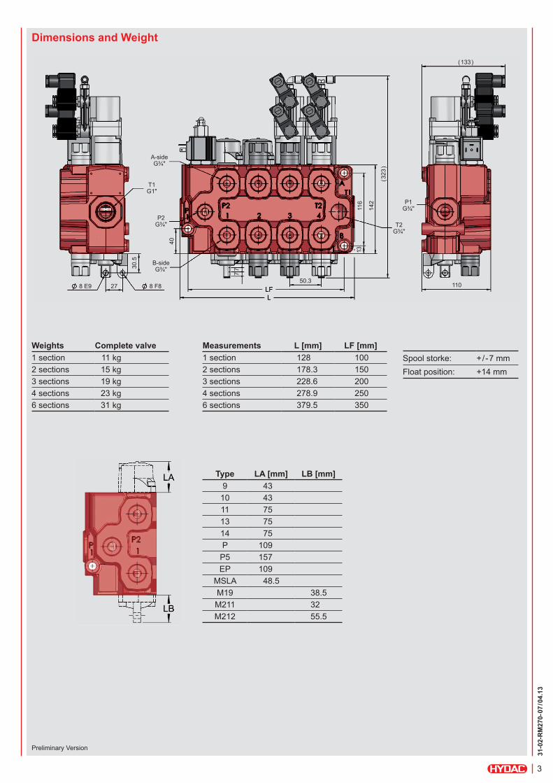
Dimensions and Weight
Weights Complete valve1 section 11 kg2 sections 15 kg3 sections 19 kg4 sections 23 kg6 sections 31 kg
Measurements L [mm] LF [mm]1 section 128 1002 sections 178.3 1503 sections 228.6 2004 sections 278.9 2506 sections 379.5 350
Type LA [mm] LB [mm]9 4310 4311 7513 7514 75P 109
P5 157EP 109
MSLA 48.5M19 38.5M211 32M212 55.5
A-sideG¾"
P2G¾" T2
G¾"
P1G¾"
B-sideG¾"
40
7
1311
6
142
(323
)
(133)
50.3110
7
30.5
8 F88 E9 27
T1G1"
Spool storke: +/-7 mmFloat position: +14 mm
Preliminary Version

31-0
2-R
M27
0-07
/04.
13
4
Main Relief Valve TBD200The TBD200 is a differential area, direct acting relief valve for the main circuit.
z Adjustable and sealable z Setting range: 35 – 210 bar (3.5 – 21.0 MPa)
z Setting range step: 5 bar
Port Relief Valve TBD205The TBD205 is a differential area, direct acting relief valve for the secondary circuit.
z Adjustable and sealable z Setting range: 40 – 210 bar (4.0 – 21.0 MPa)
z Setting range step: 10 bar
Main Relief Valve
Service Port Valves
Port Relief and Anticavitation Valve TBSD205The TBSD205 is a differential area, direct acting relief and anticavitation valve for the secondary circuit.
z Adjustable and sealable z Setting range: 40 – 210 bar (4.0 – 21.0 MPa)
z Setting range step: 10 bar
∆P (bar)
∆P (bar)
∆P (bar)
l/minQ
Ql/min
l/minQ
Preliminary Version

31-0
2-R
M27
0-07
/04.
13
5
Anticavitation Valve SB205The anticavitation valve service to ensure that, in the event of a lower pressure in the cylinder port than in the tank, oil can be drawn from the system oil tank to the consumer.
∆P (bar)
l/min
Electrical Unloading Valve
Data
Power consumption 14 WRated voltage 12 and 24 VMax voltage variation +/-10 %Duty factor 100 %
Connection Hirschmann ISO 4400-DIN 43650
Protection class IP65
IS12Manual override with push operation 12 V.
IS24Manual override with push operation 24 V.
Q
Preliminary Version

31-0
2-R
M27
0-07
/04.
13
6
Spool controls – A-side Spool controls – B-side
Spool control 9
9 Spring centered9W for cable control
Spool control 10
Detents at positions 1, 2 and 3
Spool control 11
Spring centering with detent at position 4
Spool control 13
Spring centering with detent at position 2
Spool control 14
Spring centering with detent at position 3
Spool control P
Pneumatic*
Spool control EP
Electro / pneumatic on / off**
Spool control P5
Pneumatic control with detent at position 4*
Spool control EP5
Electro / pneumatic on / off with detent in position 4**
Spool control MSLA
Spool control, stroke limitation
* Connection G1/8" BSP ** Power consumption 4.8 W Rated voltage 24 V Max voltage variation +/-10 % Duty factor 100 % Connection according to EN175301-803/B Protection class IP65
Bracket M19
Bracket for 3-position spool
Bracket M211
Bracket for 4-position spool and for 4-pos EP-spool control
Bracket M212
Bracket for 4-position spool with manual control
Preliminary Version
31-0
2-R
M27
0-07
/04.
13
7
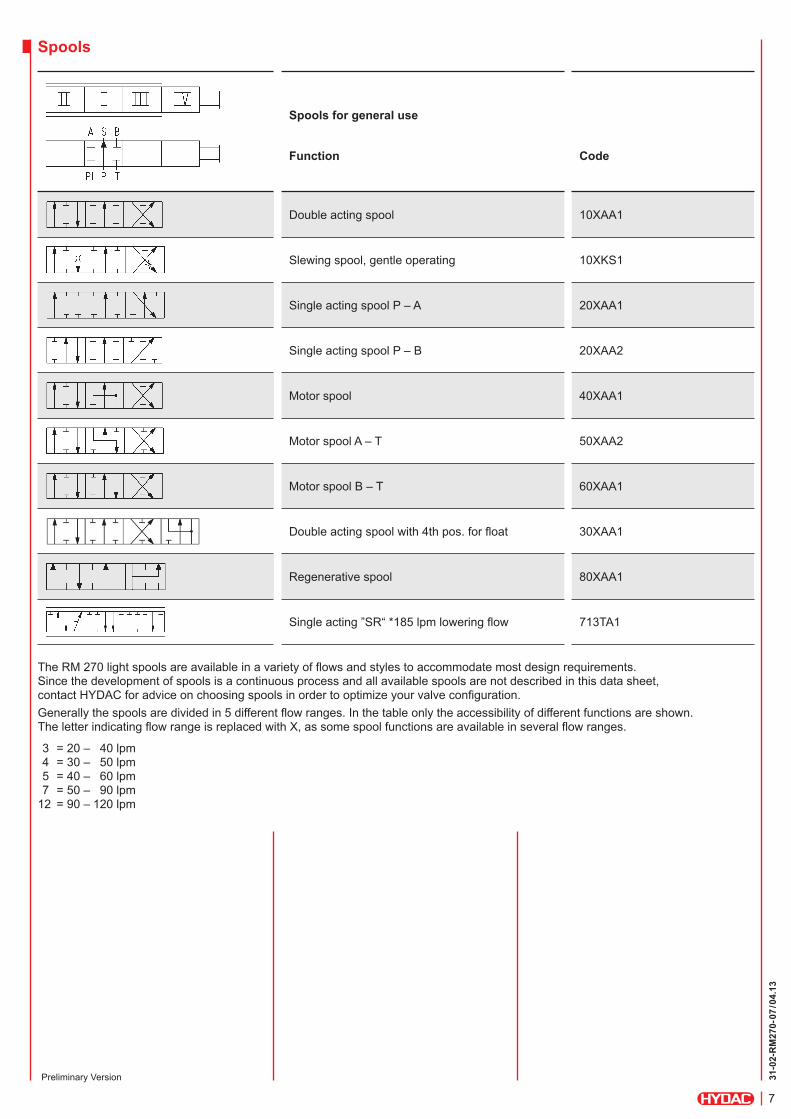
Spools
Spools for general use
Function Code
Double acting spool 10XAA1
Slewing spool, gentle operating 10XKS1
Single acting spool P – A 20XAA1
Single acting spool P – B 20XAA2
Motor spool 40XAA1
Motor spool A – T 50XAA2
Motor spool B – T 60XAA1
Double acting spool with 4th pos. for float 30XAA1
Regenerative spool 80XAA1
Single acting ”SR“ *185 lpm lowering flow 713TA1
The RM 270 light spools are available in a variety of flows and styles to accommodate most design requirements. Since the development of spools is a continuous process and all available spools are not described in this data sheet, contact HYDAC for advice on choosing spools in order to optimize your valve configuration.Generally the spools are divided in 5 different flow ranges. In the table only the accessibility of different functions are shown. The letter indicating flow range is replaced with X, as some spool functions are available in several flow ranges.
3 = 20 – 40 lpm 4 = 30 – 50 lpm 5 = 40 – 60 lpm 7 = 50 – 90 lpm 12 = 90 – 120 lpm
Preliminary Version

31-0
2-R
M27
0-07
/04.
13
8
High pressure carry-over
High pressure carry-over plug SG25The type SG25 series nipple is used for series mounting of valve blocks when pipe or hose is used between the blocks.For RM 270 light Super Rapid see page 10.
High pressure carry-over flange kit SC250The type SC250 flange kit is used to connect valve blocks in series, without any pipe or hose.For RM 270 light Super Rapid see page 10.
When high pressure carry over SG25 or SC250 is used for series mounting, the tank connection T2 for the first valve must always be connected to the tank (see diagram above). Valve blocks connected in series give priority of flow to the first block in the series. This means that there will be no flow at block 2 if block 1 is fully activated.
High pressure carry-over
Preliminary Version

31-0
2-R
M27
0-07
/04.
13
9
Integrated pressure carry-over function and extra check valve
The valve is made from a 1 section valve with a shuttle spool to create the pressure carry-over function, and an extra check valve in the pressure line. Carry-over pressure can be obtained from both A and B port, depending of which is used. The built in shuttle spool makes it possible to use the return flow from, for instance, a hydraulic winch motor on a cable lift, to regulate the downward movement of the tipper cylinder at the same time as the winch pulls the platform on the frame. The check valve prevents the oil from running backwards in the system when only the tipper valve is used.
To tipper cylinder on trailer
1. Dual-flow valve, separately mounted2. Directional control valve with internal pressure carry-over
function and extra check valve3. Directional control valve for tipper function
Preliminary Version

31-0
2-R
M27
0-07
/04.
13
10
“Super Rapid” – tipping valve configuration
The “Super Rapid” tipping valve is optimized for maximum lowering flow. The multi section valves allows lowering at the same time as another function is pressurized. The valve can be equipped for variable pump operation. The valve is available with 1, 2 and 3 sections.
It is not possible to use a high pressure carry-over nipple SG25 or flange kit SC250 in a RM 270 light Super Rapid valve with only one section.
Each valve section can be provided with a pressure relief valve, an anticavitation valve or a combination of these.
The valve can be provided with pneumatic or electro/pneumatic spool control.
Technical dataMax. system pressure: 210 bar (21.0 MPa)Max. return pressure: 20 bar (2.0 MPa)Max. lowering flow: 185 l/min
The valve can be configured for refuse vehicles. Typical is 1 four-sectional valve or 2 two-sectional valves for the functions tailgate, packing and exhaust. The pressure to the exhaust cylinder is controlled of the packing pressure so that the pressure is low during the packing cycle but high during exhaust. The circuit shows a two sectional valve with the functions tailgate on section 1 and exhaust on section 2. The valve for the packing functions is supplied from port S.
Typical configuration for refuse truck application
Preliminary Version

31-0
2-R
M27
0-07
/04.
13
11
Notes
31-0
2-R
M27
0-07
/04.
13
12
NoteThe information in this brochure relates to the operating conditions and applications described. For applications or operating conditions not described, please contact the relevant technical department.Subject to technical modifications.
Head Office Industriegebiet HYDAC INTERNATIONAL 66380 Sulzbach/Saar GMBH Germany Phone: +49 6897 509-01 Fax: +49 6897 509-577 E-mail: [email protected] Internet: www.hydac.com