Embed Size (px)
Citation preview

88
Monitoring Ageing CCVTsPractical Solutions with Modern Relays to Avoid Catastrophic FailuresBogdan Kasztenny, Ian Stevens
AbstrAct - Ageing Coupling Capacitor Voltage Transformers (CCVTs) can pose safety problems and possibly restrain system operations. Catastrophic failure of a CCVT could start a wide-spread fault in the substation and/or endanger personnel work-ing in a close proximity. The latter becomes a real danger when inspecting a suspicious CCVT or when Live Line work is being performed. CCVT monitoring becomes more and more impor-tant as the installed population of CCVTs ages with sporadic incidents of catastrophic failures alerting both field personnel and dispatching managers regarding safety and liability.
Microprocessor-based protection relays facilitate cost-efficient and broad deployment of CCVT monitoring functions across the organization.
First, modern relays allow programming a number of indica-tors that alone, or in combination, are reliable enough to raise alarms and initiate an in-depth engineering analysis.
Second, these relays can provide data recording and remote access. This data includes high-resolution data such as oscil-lography, and long-term trending such as the magnitude profil-ing.
Third, relay-based CCVT monitoring schemes can be retrofitted in the existing installations. In many cases with a simple wiring and setting changes, existing relays could provide a solid CCVT health indication.
The combination of reliable alarming via protective relays with remote access yields a cost-efficient, easy to implement, and safe to operate, solution.
This paper presents a number of CCVT health indicators that could be programmed on modern relays via logic and simple math operands in order to monitor the CCVTs with a minimum material and labor investment.
1. IntroductionCCVTs are widely used in transmission and distribution
substations to provide proportional, secondary single-, or three-phase voltages for protection, metering and control functions. The CCVT has three basic components: a capacitor divider made from a group of high voltage capacitors and a lower voltage grounding capacitor(s), and a voltage transformer/filter element which provides the single phase secondary voltage (Figure 1).
One common problem in electricity supply is the ageing population of CCVTs (Figure 2). Over many decades, the CCVT components will degrade and/or experience overvoltages. This may result in capacitor element failure and the secondary voltage progressively losing its integrity, but more importantly, the CCVT can explode if sufficient number of capacitor elements fail. The explosion can rupture the porcelain shell and radiate
porcelain fragments and hot synthetic oil within the local area (Figure 3). This debris is a real threat to staff safety and to surrounding plant (in a similar incident in a capacitor bank, Powerlink Queensland suffered damage to 26 plant items from a capacitor can explosion). In addition, the CCVT is commonly located on the substation bus and bus protection will clear the fault. This can result in loss of supply to a large number of customers and possibly incur a penalty from the Energy Regulator. Where CCVT supplies degrading voltages to revenue metering, the billing data will contain an error. The billing discrepancy can be substantial if the magnitude or phase error is small enough to remain undetected for very long periods of time, but large enough to accumulate into a significant energy measurement error.
Powerlink is replacing its line protection relays with microprocessor-based protection relays and it is beneficial and cost effective to provide VT monitoring within this relay.
Emerging considerations in Australia are the legal requirement for managers to exercise Duty of Care, especially with respect to staff safety [2]. This consideration requires managers to ensure staff safety in the substation and approved procedures exist for staff to safely isolate faulty HV assets.
This paper provides methods of monitoring with microprocessor-based protection relays and providing information for safely isolating CCVT assets, in a timely manner and thus maintaining security of supply. In addition, novel methods of monitoring a single phase CCVT are presented.
2. Failure Modes and ConsequencesThe failure modes for conventional CCVTs are:
• Failure of one or more capacitor elements in the HV stack (C1), which is usually oil impregnated. The critical factor is the increase in voltage and stress upon healthy capacitors as each capacitor fails, e.g. 275kV CCVT has about 160 capacitors in C1. This can lead to an avalanche failure mode and a possible explosion.
• Failure of one or more capacitor elements in the LV grounding stack (C2), which is usually oil impregnated. The important factor is the decrease in secondary voltage. However, this failure mode can result in an explosion as experienced in New Zealand when C2 failed due to a faulty connection.
• Failure of the intermediate voltage transformer or the series reactor, which can result in changes in phase angle and/or voltage.
• Failure of the ferroresonance suppression circuit, which can produce waveform distortion, changes in phase angle and/or voltage. It is possible for ferroresonance events to occur if the connected burden has too low a knee point voltage in

8�
its transformer(s). Powerlink experienced an intermittent connection in the CCVT’s ferroresonance damping circuit and this fault produced a reasonably stable voltage (64V compared to 67V on healthy phases) and fluctuating frequency in one phase between 47 to 53 Hz (50Hz nominal; measured with
DMM) in the output voltage. Investigation revealed there was an open circuited choke in the ferroresonance damping circuit in the CCVT basebox due to an imperfectly soldered joint in the wire, within a sleeve in the choke toroid. This open circuit had the effect of directly shunting portion of the VT primary winding
Fig. 1. Construction of a typical CCVT [1].
0
50
100
150
200
250
300
< 19
60
1960
-196
5
1966
-197
0
1971
-197
5
1976
-198
0
1981
-198
5
1986
-199
0
1991
-199
5
1996
-200
0
2001
-200
5
Fig. 2. Distribution of CCVTs purchased by Powerlink (sample plant, all still in service).

�0
with a capacitive impedance rather than the normal high 50Hz impedance and would have affected the voltage output.
• Failure of the filter circuit or spark gaps, which are used to minimize harmonic and transient voltages in the output voltage. Frequent overvoltage events can wear out the spark gap and the flashover voltage level increases. This will increase the stress on components in the VT circuit and these eventually fail.
• External flashover along the porcelain bushing due to pollution contamination of flashover clearance. The cause is incorrect CCVT specification for the local environment when purchasing the CCVT.
• Failure of expansion membrane, which results in contamination of oil and capacitor failure. Powerlink has experienced failure of the expansion membrane in a magnetic VT because the membrane was incompatible with the synthetic oil. This eventually resulted in the VT exploding.
Fig. 3. Porcelain debris after rupture of a VT.
• Failure in gasket seal which may allow high moisture content (>30 ppm) in oil which reduces the withstand voltage capability and increases stress in basebox items which use oil impregnated paper.
• Low oil condition due to prolonged oil leak which results in capacitor failure.
The capacitor, series reactor and intermediate voltage transformer components can be degraded by high harmonic currents (e.g. AC-powered trains), lightning or prolonged ferroresonance conditions.
The consequences of CCVT failure could be:
• The CCVT can explode if sufficient number of capacitor elements fail and arcing occurs within it . The explosion can rupture the porcelain shell and radiate porcelain fragments and hot synthetic oil within the local area. This debris is a real threat to safety of staff and to surrounding plant.
• The CCVT is commonly located on the substation bus and bus protection will clear the fault. This can result in loss of supply to a large number of customers, or weakened system integrity (stability problems).
• The failure mechanism was due to a generic or age related fault. Thus the remaining CCVTs could be deemed suspect and, without monitoring, result in constraints upon system operations and substation work.
• Progressive failure over a long period of time will cause incorrect revenue billing because one secondary voltage was incorrect. Microprocessor revenue meters will alarm if the voltage exceeds the typical limits of 80% to 115%. CCVT monitoring can overcome this problem, eliminate the need to repay/recoup the amount of incorrect billing and maintain a company’s reputation.
3. Present Monitoring SchemesThe present monitoring schemes are limited to three-
phase groups of CCVTs. The commonly used methods are based on under/over voltage protection relays, which create an operational window and alarm for voltages outside the window (except for near zero voltage where the CCVT was de-energised). This method is an absolute measurement and is relatively insensitive because the window thresholds must be set above possible network voltage fluctuations (±10% of nominal). Therefore, the alarm could be raised just before the CCVT could explode.
A novel method developed by TransGrid (an Australian transmission authority) was to monitor the half wave rectified, three-phase voltages with a missing pulse detector [3]. A high voltage will cause its rectified phase pulse to dominate, thereby causing one healthy pulse to be missed (Figure 6). A low voltage will cause its rectifying diode to be biased off, thereby causing the phase pulse to be missed. The missing pulse detector fed into a time delay and output relay circuits. This method is sensitive to voltage but relatively insensitive to phase drift as detection occurs around ±60º. This method is a relative three-phase method, and it has been successful. However, it requires a separate relay for each three-phase CCVT and it cannot provide additional information as to which phase failed.
These monitors were set with a 10 minute time delay so that any transient voltage fluctuations from the electricity network or secondary system loads is filtered out. The time delay prevents incorrect and unnecessary alarms, which can give CCVT monitoring a bad reputation with resulting distrust and poor response to legitimate alarms.
Dissolved gas analysis of oil samples taken from CCVTs will provide static assessment on the health of each CCVT. The
�1
disadvantages are high cost and labour requirements, and it’s possible the CCVT could fail between oil samples.
4. Attributes for CCVT MonitoringThe required attributes for CCVT monitoring are:
• Continuous, reliable monitoring is provided and the alarms are supervised.
• It uses a relative voltage measurement technique so as to give sensitive monitoring irrespective of unrelated transient voltages. Microprocessor-based protection relays measure zero sequence and/or negative sequence voltages providing for this attribute.
• It logs the voltages in a FIFO record of suitable length and frequency for post fault analysis.
• It filters out transient sequence events such as secondary transient loads on one phase, network faults or switching of reactive assets such as shunt capacitor banks and reactors. Typically, a long time delay is used but this can still produce fleeting alarms that may be ignored by the operator.
• The installed and maintained costs for providing monitoring are low as the frequency of CCVT faults is very low but the consequences of a fault are very high and costly. The cheapest monitoring available is to incorporate it into existing feeder protection or SCADA control equipment. This equipment already has three-phase voltages connected, and may provide
a SCADA communication link (such as DNP 3.0) to annunciate CCVT alarms.
• The provision of voltage waveforms in real time or as records allows staff to investigate the problem and take appropriate actions to maintain staff safety and security of supply.
• The above information is provided by remote interrogation and in a timely manner. Powerlink has developed a 2MB Wide Area Network (WAN), which connects to the majority of substations and it enables remote interrogation within 5 minutes.
Modern microprocessor-based protection relays provide many of these attributes and are ideal for performing this monitoring.
5. System Conditions and Voltage Monitoring
Operating range of electricity network is typically ±10% of the nominal voltage. However under system abnormal conditions (e.g. one feeder out for maintenance and an associated supply feeder trips), it may be possible for three phase voltage dips or brown out events to occur. It is important that resultant, incorrect CCVT monitoring alarms do not occur and increase the workload of network control centre operators during this crisis.
The electricity network is designed to limit the levels of the negative-sequence voltage to a maximum 2% averaged over
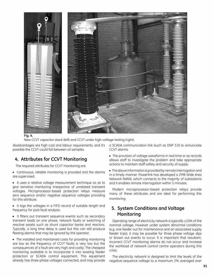
Fig. 4. New CCVT capacitor stack (left) and CCVT under high-voltage testing (right).

�2
a 1-minute period. The quiescent level is typically around 0.5%. This limit was derived from the adverse impacts upon motors producing torque in the opposite direction and overheating their rotors if exposed to negative-sequence. For example, NEMA recommends keeping the continuous negative-sequence unbalance to within 1% [4]. Therefore, these levels will give guidance for selecting the pick up value and minimum operating time for CCVT monitoring. Some extra high voltage networks are operated untransposed with significant negative-sequence in currents and voltages. If this is the case, zero-sequence voltage could be considered instead.
Any measurement grade VT is designed for operation under any burden conditions such that magnitude and phase errors are less than accuracy class, which usually have limits of 1.5% and 1º. However, VT burdens are generally balanced so there will be minimal magnitude and phase differences between phases, i.e. all magnitude and phase errors will have the same sign.
Therefore under healthy CCVT conditions and with no negative sequence voltage in the electricity network, there will be negligible negative-sequence voltage.
The major consideration in the electricity network is power system faults which are limited to around 10s duration. Therefore, the negative-sequence time guideline will supersede this requirement.
6. Proposed Voltage Monitoring Schemes 6.1. Methods for three-phase sets of CCVTs
The advent of microprocessor-based protection relays can give the opportunity to provide CCVT monitoring at virtually no additional cost. The commonly used transmission feeder
protection systems are distance protection and/or current differential protection, which may have distance back up protection. The distance protection function requires three-phase voltages and hence it is ideal to perform CCVT monitoring. The new method can be applied on these relays utilizing their metering, logic and math capabilities.
One design objective was to eliminate the need to wire the CB status into the monitoring system. Therefore, overvoltage elements are set low (15-20% of nominal) to indicate the VT is energised. Note if the capacitively coupled voltage on a de-energised bus or feeder is high, it may be necessary to increase the supervising setting.
6.1.1 Monitoring with Negative-Sequence Voltage
Negative-sequence voltage is a preferred monitoring method because it provides relative coverage over the whole voltage phasor range, and negative-sequence overvoltage elements are often available in microprocessor-based protection relays for purposes such as weak-infeed logic.
Assume phase A is failing while phases B and C display virtually no errors. The negative-sequence derived from such voltages is:
( ))()(2
(sec)2 31
primCprimBA VaVaVV ⋅+⋅+= (1)
which can be re-written as:
( ))()(2
2(sec) 3 primCprimBA VaVaVV ⋅+⋅−⋅= 2)
Expression in the brackets is minus the primary ratio voltage in phase A, and therefore:
)(2(sec) 3 primAA VVV +⋅= (3)
Equation (3) means that assuming balanced primary voltages, and phase A voltage failing, the negative-sequence overvoltage function defines a limit around the true ratio voltage in the shape of a circle with the radius of three times the applied pickup (Figure 7).
This provides for good sensitivity to angle shifts in the monitored voltage. Assuming the VA magnitude does not change and the failure shifts the vector, the following shift will trigger the negative-sequence function if set to pickup at V2.
(4)
And furthermore:
(5)
For example, if set to 0.03pu, the negative-sequence overvoltage function would trigger when the secondary voltage shifts by about 5.2 degrees. This is the
Fig. 5. Examples of failed CCVT capacitor stacks.
)(2
2
23arcsin2
23arcsin2 PU
A
VVV
)(2(deg)1803
PUV

�3
worst case scenario; if the magnitude changes, either increases or decreases, even smaller angle differences will trigger the negative-sequence function (see Figure 7).
However, sensitivity to magnitude changes is lower. Assume no angle error occurs as a result of the failing CCVT. It will take a magnitude excursion of 3 times the negative-sequence pickup to trigger an alarm. For example, with a 0.03pu pickup, it will take a change in magnitude by 9% to trigger the alarm. This may be considered not sensitive enough.
The high voltage capacitor stack (C1) may be composed of one hundred cans at 132kV level, 160 cans at 275kV level, etc. Approximately, the voltage ratio changes in proportion to the amount of shorted capacitor cans. For example, at 275kV level with 160 cans, it will take 2 cans to cause a change of 1.2% in the voltage; a single can failure would cause a 0.6% change, which could be below the class error of the transformer. This sets a limit on the minimum number of shorted cans that could be detected. Failures of the low voltage stack have a more dramatic effect on the ratio and could be detected much easier.
Sensitivity to magnitude excursions can be improved by monitoring differences between the magnitude of the A phase
voltage and reference phases B and C, as shown in Figure 8.
Fig. 6. Illustration of the CCVT monitor [3].
Fig.�. Operating region of the negative-sequence overvoltage assuming B and C voltages normal.
3V2
VA(sec)
VA(prim)
VB(prim)VC(prim)

�4
A delay timer is applied to ride through faults, single-pole tripping and reclosing sequences and other switching events. Applying scheme of Figure 8a, a normal/alarm operating region is shaped as shown in Figure 8b.
Typical settings are negative-sequence overvoltage pickup of 0.03pu (D1 threshold), magnitude differential pickup of 0.06pu (D2 threshold), 120sec time delay (tPKP delay), and 10 minute dropout time (tDPO delay). The 10 minute duration ensures this problem is not considered a fleeting event.
A practical implementation may require connecting two timers in series: the first timer is a zero pickup, and small dropout timer. This timer is meant to prevent reset of the main timer during sporadic situations when the negative sequence voltage drops temporarily to low values, e.g. varying frequency output from intermittent connection in CCVT ferroresonance circuit. The second timer is the main, 120 sec pickup, 10 minute dropout timer.
6.1.2 Using change over time to increase sensitivity
Method of section 6.1.1 uses a steady state approach: it detects abnormal situation after it occurs and continues to be steady state. For example, when a can fails short in the HV stack of the divider, the magnitude of the secondary voltage increases and is driven by a permanently higher ratio. A failure in the tuning reactor can lead to a permanent phase shift in the secondary voltage. Because of the relatively long time delay, the method requires the failure to “stabilize” before it could detect it . At the same time the lowest possible pickup level must be above the normal steady-state difference between the phases.
In order to make the detection more sensitive, a change over time for the differential magnitudes could be applied as shown in Figure 9.
First, the difference between the two voltage magnitudes is derived. This difference may be as high a 2-3% under normal conditions, requiring the threshold in the previous method to be well above that level.
Second, the change over time is measured by comparing the present value of the difference with its historical, T sec old value. If a change greater than D3 occurs, the output of
the comparator is asserted. The value of T is set to 200-300 seconds. The threshold could be set as low as 0.02pu. Here, the steady state errors in the CCVTs and the relay are filtered out by using the change over time. Also, the natural fluctuations in each individual voltage are filtered out by using the differential magnitude voltage.
Third, the output of the “differential over time” comparator is connected to a timer (set at 120 sec).
Figure 10 illustrates this principle by showing the A and B voltage magnitudes (a), the magnitude differential (b), change over time of the differential, and the operating flag (c).
This method will generate a single alarm and it will reset afterwards. This must be taken into account when programming post-filtering of alarms generated by this version of the logic.
Methods of Figures 8 and 9 shall be used together to produce permanent alarm on substantial voltage deviations (Fig.8), and single alarm on small voltage deviations (Fig.9).
| VA |O
R tPKPtDPO
TIMER
ALARM| VB |
| VA || VC |
| ||VA| - |VB||(t) - ||VA| - |VB||(t-T) | > D3
| ||VA| - |VC||(t) - ||VA| - |VC||(t-T) | > D3
Fig. �. Monitoring logic responding to fluctuations of the differential magnitude.
6.2. Methods for single CCVTs
Presently single phase CCVTs are not monitored at Powerlink because of the difficulty in obtaining a reliable reference quantity.
6.2.1 Monitoring with Negative-Sequence Voltage via Pseudo Three-phase Arrangement
The three-phase steady state method of section 6.1.1 can be used for this purpose assuming one could “borrow” the two other phases from CCVTs that are measuring the same primary voltage. Quite often this is possible. A single CCVT on the bus facilitating synchrocheck against a three-phase full set of line CCVTs is a typical case.
| V2 | > D1
VA
VB
VC
| |VA| - |VB| | > D2
| VA |
OR tPKP
tDPO
TIMER
ALARM
(a) (b) 3D1
(1+D
2)*V A(
prim
)
(1-D
2)*V A
(prim
)
NORMAL
ALARM
123arcsin2 D
| VB |
| VA || VC |
| |VA| - |VC| | > D2
Fig. 8. Negative-sequence overvoltage monitoring logic (a) and effective operating characteristic (b). All expressions are per unit.

�5
With reference to Figure 11, extra security conditions are checked. First, using overvoltage functions one needs to make sure the monitored (VX) and the reference (VB and VC) CCVTs are energized. Second, one needs to monitor the position of breakers/disconnectors to make sure the monitored and reference CCVTs are connected to the same metallically coupled portion of the bus (i.e. the reference voltages are truly valid references). Also, if the reference CCVT is monitored, its health indicator could be used to supervise the logic.
Method of section 6.1.2 with increased sensitivity could also be used when “borrowing” other phase voltages.
6.2.2 Using reference from the same phase
This is a simple method that is based on using the reference voltage from the same phase. This could be done for a single CCVT, or for a set of three CCVTs with three pairs of voltages compared.
The comparison itself could be done using flexibility of modern relays as shown in Figure 12, or utilizing a synchrocheck function as illustrated in Figure 13.
Modern relays provide for a synchronism check function. This function can be used to monitor consistency of any two secondary voltages assuming the two CCVTs work with the same primary voltage. The three basic synchrocheck settings are selected as follows:• Magnitude difference (D7 threshold): 2.5-3 times the sum of CCVT worst-case error and relay worst-case error. This is driven by the assumption that one voltage is measured with the maximum in class negative error, while the other is measured with the maximum positive error. Therefore, the worst-case normal difference is twice the summated error of the CCVT and the relay. Assuming 1% CCVT error and 0.25% of relay error, the difference shall be set above 2.5% (4-5%).• Angle difference (D6 threshold): similar reasoning applies (twice the error of the CCVT and the relay). A 2-30 setting shall be sufficient.
Fig. 11. Monitoring single CCVT (VX = A phase) with negative-sequence while using reference voltages (VB & VC).All expressions are per unit.
tPKPtDPO
TIMER
ALARM
AND
| VX | > D4
| VB | > D4
| VC | > D4
X, B & C on the same bus
reference VT is healthy
| V2 | > D1
VX
VB
VC
| |VX| - |VB| | > D2
| VX || VB |
| VX || VC |
| |VX| - |VC| | > D2
OR
Fig. 10. Illustration of the method of Figure 9.

�6
• Frequency difference (D5 threshold): 2.5-3 times the worst-case relay frequency measurement error. For example with a 10mHz worst-case measuring error, one could set the allowable delta-frequency setting to 30-50mHz.
Normally, all three parameters (magnitudes, angles, and frequency) are identical. Should any of them divert due to CCVT failure, the synchrocheck permissive flag resets. This opens the AND-gate, starts the timer, and sends an alarm if the situation persists.
Quite often the synchrocheck function is available as a standard feature, but is not used on a given IED. This gives an opportunity to use it as a voltage differential function to monitor a CCVT against a reference voltage.
In Figures 12 and 13 the supervision from the reference CCVT being healthy is optional. If the monitor triggers an alarm, the operators should understand that either of the two CCVT could have a problem, and both should be checked.
Method of section 6.1.2 with increased sensitivity could also be used when “borrowing” the same phase CCVT for reference.
tPKPtDPO
TIMER
ALARM
AND
| VA | > D4
| VA(REF) | > D4
A & A(reference) on the same bus
reference VT is healthy
| |VA| - |VA(REF)| | > D2
| VA |
| VA(REF) |
Fig. 12. Monitoring single CCVT (A phase) by comparison with the same phase of a different CCVT.
∆f < D5∆φ < D6∆V < D7
VA
VB
VC
tPKPtDPO
TIMER
ALARM
AND
IN SYNCH
| VX | > D4
| VS | > D4
X, A, B & C on the same bus
reference (ABC) VT is healthy
VX
select tomatch
SYNCHROCHECK
VS
Fig. 13. Monitoring single CCVT by comparison with the same phase of a different CCVT (application of the synchrocheck function).
6.2.3 Providing alternate reference VT
These monitoring schemes rely upon a reference VT, and it may be required to provide monitoring when the reference VT is de-energized. This is easily achieved by:
• A simple armature relay to appropriately select another reference VT;• Within the relay, creating a monitoring scheme for each reference VT and ORing the outputs. (The above monitoring methods will not provide an output when the reference VT is de-energized.)
6.3. Additional Filtering of Alarms
The CCVT monitoring alarm outputs are sent in real time to the network control centre over SCADA for operator investigation.
Powerlink has decided to perform post processing by computer of all alarms received at the control centre. The aims are to detect high frequency of plant operation (e.g. tap changer operation of transformer) and to detect fleeting alarms, which may not be detected by humans.
CCVT monitoring alarms fall into the second aim and this is simple to achieve if a standard alarm naming convention is used. This computer filtering provides a safety net in the monitoring scheme.
Table 1 shows an extracted alarm record of a failing CCVT at a control centre.
6.4. Additional Features of Microprocessor-based Relays
Microprocessor-based protection relays provide additional functions beneficial for CCVT monitoring. Importantly, these relays provide oscillographic and event recording and data logging of voltages; all these can be remotely accessed over a communication link by the control centre operator (Figure 14). This enables quick, safe interrogation of possible CCVT failure and prompt removal of plant before a possible explosion and resultant supply interruption. This information is very useful for CCVT repair and detecting generic faults due to CCVT age or design related faults.
These additional features are extremely useful and cost effective to Powerlink.
�. Implementation on Modern RelaysModern microprocessor-based protection relays provide for
simple math capabilities. The CCVT monitoring function is not time critical, therefore a generic PLC-like math operations could be used for this purpose.
One particular solution uses a universal comparator to perform comparison, or rate-of-change monitoring for analog signals.
With reference to Figure 15 the universal comparator could have up to two signals configured as inputs in a differential mode. These inputs are any signals measured by the relay and include phasor magnitudes and angles, true RMS value, active and reactive power, magnitudes and angle of symmetrical currents and voltages, frequency, power factor, etc. Either two signals are subtracted (Figure 16a), a single signal is used (Figure 16b), a single inverted signal is used (Figure 16c), or a sum of two signals is used by cascading two comparators (Figure 16d).
The comparator could be set to respond to “signed” or “absolute” value of the effective operating (differential) signal. The absolute value allows for symmetric response for positive and negative values; the signed value allows for monitoring both the value and its sign. For example, to alarm on low power

��
DATE ALARM DESCRIPTION DURATION1/10/2003 16:36:32 R-9 H016-RLEA 110KV FDR CCVT VOLTAGE ABNORMAL->NORMAL 0:14:39 31/10/2003 1:59:20 R-9 H016-RLEA 110KV FDR CCVT VOLTAGE ABNORMAL->NORMAL 0:12:49 31/10/2003 2:14:00 R-9 H016-RLEA 110KV FDR CCVT VOLTAGE ABNORMAL->NORMAL 0:10:10
31/10/2003 10:42:05 R-9 H016-RLEA 110KV FDR CCVT VOLTAGE ABNORMAL->NORMAL 0:15:41 31/10/2003 13:31:45 R-9 H016-RLEA 110KV FDR CCVT VOLTAGE ABNORMAL->NORMAL 0:16:11 31/10/2003 19:24:11 R-9 H016-RLEA 110KV FDR CCVT VOLTAGE ABNORMAL->NORMAL 0:11:30 31/10/2003 20:08:40 R-9 H016-RLEA 110KV FDR CCVT VOLTAGE ABNORMAL->NORMAL 0:16:30 31/10/2003 20:41:20 R-9 H016-RLEA 110KV FDR CCVT VOLTAGE ABNORMAL->NORMAL 0:18:20 31/10/2003 20:57:02 R-9 H016-RLEA 110KV FDR CCVT VOLTAGE ABNORMAL->NORMAL 0:11:32 31/10/2003 21:40:50 R-9 H016-RLEA 110KV FDR CCVT VOLTAGE ABNORMAL->NORMAL 0:10:30 31/10/2003 22:20:28 R-9 H016-RLEA 110KV FDR CCVT VOLTAGE ABNORMAL->NORMAL 0:10:50
1/11/2003 9:17:23 R-9 H016-RLEA 110KV FDR CCVT VOLTAGE ABNORMAL->NORMAL 0:15:19 1/11/2003 9:42:43 R-9 H016-RLEA 110KV FDR CCVT VOLTAGE ABNORMAL->NORMAL 0:10:31
1/11/2003 11:18:13 R-9 H016-RLEA 110KV FDR CCVT VOLTAGE ABNORMAL->NORMAL 0:11:42 1/11/2003 12:00:41 R-9 H016-RLEA 110KV FDR CCVT VOLTAGE ABNORMAL->NORMAL 0:10:50 1/11/2003 17:45:30 R-9 H016-RLEA 110KV FDR CCVT VOLTAGE ABNORMAL->NORMAL 0:12:52 1/11/2003 18:46:18 R-9 H016-RLEA 110KV FDR CCVT VOLTAGE ABNORMAL->NORMAL 0:13:58 1/11/2003 21:02:18 R-9 H016-RLEA 110KV FDR CCVT VOLTAGE ABNORMAL->NORMAL 0:11:21 1/11/2003 22:32:17 R-9 H016-RLEA 110KV FDR CCVT VOLTAGE ABNORMAL->NORMAL 0:17:59 2/11/2003 1:21:56 R-9 H016-RLEA 110KV FDR CCVT VOLTAGE ABNORMAL->NORMAL 0:11:30 2/11/2003 1:48:14 R-9 H016-RLEA 110KV FDR CCVT VOLTAGE ABNORMAL->NORMAL 0:11:20
2/11/2003 10:19:10 R-9 H016-RLEA 110KV FDR CCVT VOLTAGE ABNORMAL->NORMAL 0:12:10 2/11/2003 11:55:39 R-9 H016-RLEA 110KV FDR CCVT VOLTAGE ABNORMAL->NORMAL 0:12:30 2/11/2003 22:23:33 R-9 H016-RLEA 110KV FDR CCVT VOLTAGE ABNORMAL->NORMAL 0:11:28 3/11/2003 2:11:43 R-9 H016-RLEA 110KV FDR CCVT VOLTAGE ABNORMAL->NORMAL 0:15:20 3/11/2003 4:25:51 R-9 H016-RLEA 110KV FDR CCVT VOLTAGE ABNORMAL->NORMAL 0:15:31
3/11/2003 10:52:57 R-9 H016-RLEA 110KV FDR CCVT VOLTAGE ABNORMAL->NORMAL 0:13:30 3/11/2003 11:36:58 R-9 H016-RLEA 110KV FDR CCVT VOLTAGE ABNORMAL->NORMAL 0:15:00
Total 28Maximum Time= 0:25:41 Minimum Time= 0:10:10 Average Time = 0:13:38
Table 1. Sample of SCADA logs prompting operators to investigate.
Fig. 14. Example of remote interrogation of a microprocessor-based protection relay. The site is 1,800km (1,110 miles) away.

�8
factor one would use the “absolute” mode (Figure 17a). But to alarm separately on low leading, and low lagging power factor, one would use two comparators set in the “signed” mode (Figure 17b).
The comparator allows responding to either the value of the effective operating signal (“level” mode) or the change of the signal over a pre-defined period of time (“delta” mode). The former could be used to define functions such low power factor alarm, positive sequence undervoltage, negative-sequence overcurrent, over-frequency, under-frequency, etc. The later allows defining custom functions such rate-of-change-of-frequency, rate-of-change-of-power, etc.
Finally, the comparator could be set to perform “over” or “under” comparison against a constant user-selectable threshold. The hysteresis is user-adjustable too.
Figure 18 shows an application example for the logic of Figure 8. In this example FlexElements 1 and 2 (universal comparators) are used to monitor the voltage magnitude differences, while negative-sequence over-voltage function is set to monitor the unbalance. OR-gate no.1 and Timer 1 are used to complete the logic circuit. The “CCVT ALARM” flag is set to drive and output contact or alarm via communications.
8. ConclusionsThe causes for CCVT failure and electricity network events
were presented. From these conditions, it was possible to develop monitoring schemes and settings, which will give reliable alarms to network control centre operators for action. Various monitoring schemes suitable for three-phase and single-phase CCVTs were presented.
Microprocessor-based protection relays contain the functions necessary to perform monitoring on an incremental cost basis. Importantly, these relays provide oscillographic, event and data logging recording of voltages, which can be remotely accessed over a communication link. This enables a quick, safe interrogation of possible CCVT failure and prompt removal of plant before a possible explosion and resultant supply interruption. This information is very useful for CCVT repair and detecting generic faults due to age or inadequate design.
The benefits to an organization are improved security of supply, enhanced staff safety and continuance of reputation and goodwill with its customers. In addition, within the National Electricity Market in Australia, a considerable annual reward or penalty can be received based upon security of supply performance against specified levels.
sign
ed/a
bsol
ute
leve
l/del
ta
+
-
Input Plus
Input Minus
OpSignalabs(.) x(t)- x(t-T)
tPKPtDPO
TIMER
OP
PKP
X
over
/und
er
Y < C
YY > C
Fig. 15. Operating logic of the universal comparator.
+
-
Vab mag
Vbc mag
OpSignal 1
OpSignal 1 = Vab mag - Vbc mag
(a)
+
-
PowerFactor
Off
OpSignal 2
OpSignal 2 = PowerFactor
(b)
+
-
Off
ActivePower
OpSignal 3
OpSignal 3 = - ActivePower
(c)
+
-
Off
ActivePower1
OpSignal 4
OpSignal 4 = - ActivePower1
(d)
+
-
ActivePower2
OpSignal 5
OpSignal 5 = ActivePower2 - (- ActivePower1) =ActivePower1 + ActivePower2
Fig. 16. Illustration of the sum/subtract capabilities of the universal comparator.

��
�. References[1] Tanaskovic M., Nabi A., Misur S., Diamanti P., McTaggart R., “Coupling Capacitor Voltage Transformers as Harmonics Distortion Monitoring Devices in Transmission Systems”, 2005 International Conference on Power System Transients (IPST), Montreal, Canada, June 19-23, 2005, paper 031.
[2] (Australian) NATIONAL OCCUPATIONAL HEALTH AND SAFETY COMMISSION ACT 1985, (http://www.nohsc.gov.au)
[3] Industrial Electronics Engineering P/L, Kirrawee (Australia), model 604Q relay.
[4] NEMA Standards Publication MG 1-2003, Motors and Generators, Section 12.45, Voltage Unbalance, NEMA, 2003.
Fig. 1�. Illustration of the absolute (a) and signed (b) modes of operation. Low power factor alarm (a), and low power factor lagging, and leading alarms (b).
Fig. 18. Settings implementing the monitoring logic of Figure 8.
x(t)- x(t-T)
Y > C
abso
lute
leve
l
+
-
PowerFactor
Off
OpSignalabs(.) x(t)- x(t-T)
LOW POWER FACTORX
unde
r
Y < C
YY > C
(a)
abso
lute
leve
l
+
-
PowerFactor
Off
OpSignalabs(.)
LOW PFX
unde
r
Y < C
Y
(b)
+
-
PowerFactor
Offabs(.) x(t)- x(t-T)
PF > 0X
Y < C
YY > 0
sign
ed
leve
l
over
OpSignal
AND
AND
LOW &LEADING PF
LOW &LAGGING PF