Embed Size (px)
Citation preview
654
MOISTURE LIQUID INDICATORS
HENRY TECHNOLOGIES SIGHT GLASSES (BULLS EYE TYPE)
HENRY TECHNOLOGIES VERTICAL ASME SUCTION LINE ACCUMULATORS
A C
B
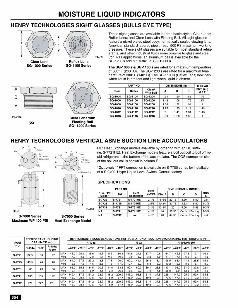
These sight glasses are available in three basic styles; Clear Lens;Reflex Lens; and Clear Lens with Floating Ball. All sight glassesfeature a nickel plated steel body, hermetically sealed viewing lens,American standard tapered pipe thread, 500 PSI maximum workingpressure. These sight glasses are suitable for most standard refrig-erants, and other industrial fluids non-corrosive to glass and steel(for R-11 applications, an aluminum ball is available for theSG-1200’s add “C” suffix i.e. SG-1206C).
The SG-1000’s & SG-1100’s are rated for a maximum temperatureof 500° F (260° C). The SG-1200's are rated for a maximum tem-perature of 300° F (148° C). The SG-1100’s (Reflex Lens) look darkwhen liquid is present and light when liquid is absent.
PART NO. DIMENSIONS (in.) THREADSIZE (in.)
M.P.T.Clear Reflex Clear/With Ball A B C
SG-1004 SG-1104 SG-1204 .94 .90 .56 1/2SG-1006 SG-1106 SG-1206 1.12 1.06 .75 3/4SG-1008 SG-1108 SG-1208 1.38 1.32 .94 1
SG-1010 SG-1110 SG-1210 1.75 1.25 1.19 1-1/4SG-1012 SG-1112 SG-1212 2 1.41 1.31 1-1/2SG-1016 SG-1116 SG-1216 2.50 1.28 1.63 1
P4453
Clear LensSG-1000 Series
Reflex LensSG-1100 Series
Clear Lens withFloating Ball
SG--1200 Series
P4453A
AB
C
Outlet
1/4"FPT ReliefConnection
Inlet
PARTNO.
REFRIGERANT HOLDINGCAP. (lb 0°F sat)
REFRIGERANT RECOMMENDED TONS REFRIGERATION AT SUCTION EVAPORATING TEMPERATURE (°F)R-134a R-22 R-404A/R-507
R-134a R-22 R-404a/R-507 +40°F +20°F +0°F -20°F -40°F +40°F +20°F +0°F -20°F -40°F +40°F +20°F +0°F -20°F -40°F
S-7721 32.5 30 27MAXMIN
43.07.7
25.14.5
15.62.8
9.31.7
5.20.9
60.410.9
41.87.5
27.65.0
17.73.2
10.81.9
64.711.7
42.57.7
27.65.0
17.13.1
10.11.8
S-7725 48.5 44 40MAXMIN
64.012.8
37.47.5
23.24.6
13.82.8
7.81.6
90.017.9
62.212.4
41.18.2
26.35.3
16.13.2
96.519.2
63.412.6
41.18.2
25.55.1
15.13.0
S-7731 80 73 66MAXMIN
95.019.1
55.511.1
34.56.9
20.54.1
11.62.3
133.526.8
92.418.6
60.912.2
39.17.9
23.84.8
143.128.8
94.018.9
61.012.3
37.87.6
22.44.5
S-7741 136 135 122MAXMIN
149.448.2
87.228.1
54.217.5
32.210.4
18.25.9
209.967.7
145.246.9
95.830.9
61.419.8
37.512.1
225.172.6
147.947.7
95.931.0
59.419.2
35.311.4
S-7742 279 277 251MAXMIN
149.448.2
87.228.1
54.217.5
32.210.4
18.25.9
209.967.7
145.246.9
95.830.9
61.419.8
37.512.1
225.172.6
147.947.7
95.931.0
59.419.2
35.311.4
S-7000 SeriesMaximum WP 400 PSI
P4454
S-7000 SeriesHeat Exchange Model
C
Outlet
1/4"FPT ReliefConnection
Inlet
E** HE Models Only
B
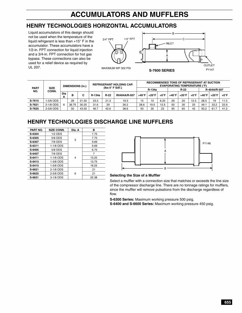
HE: Heat Exchange models available by ordering with an HE suffix(ie. S-7721HE). Heat Exchange models feature a boil out coil to boil off liq-uid refrigerant in the bottom of the accumulator. The ODS connection sizeof the boil out coil is shown in column E.
*Optional: 1" FPT connection is available on S-7700 series for installationof a S-9400-1 type Liquid Level Switch. Consult factory.
SPECIFICATIONS
PART NO.ODS
CONN.
DIMENSIONS IN INCHES1-in. FPTModel* Std Heat
Exchanger DIA. A B C D ODSE
S-7722 S-7721 S-7721HE 2-1/8 8-5/8 23.13 3.50 5.50 7/8
S-7726 S-7725 S-7725HE 2-5/8 10-3/4 22.75 4.63 5.50 1-3/8S-7732 S-7731 S-7731HE 3-1/8 12-3/4 25 5.50 5.88 1-3/8NA S-7741 S-7741HE 4-1/8 16 35.50 Contact Factory 2-5/8
NA S-7742 — 4-1/8 20 44.50 Contact Factory N/A
P4454
655
ACCUMULATORS AND MUFFLERS
HENRY TECHNOLOGIES HORIZONTAL ACCUMULATORSLiquid accumulators of this design shouldnot be used when the temperature of theliquid refrigerant is less than +15° F in theaccumulator. These accumulators have a1/2-in. FPT connection for liquid injectionand a 3/4-in. FPT connection for hot gasbypass. These connections can also beused for a relief device as required byUL 207.
S-7600 SERIES P1147
HENRY TECHNOLOGIES DISCHARGE LINE MUFFLERS
PARTNO.
SIZECONN.
DIMENSIONS (in.) REFRIGERANT HOLDING CAP.(lbs 0° F SAT.)
RECOMMENDED TONS OF REFRIGERANT AT SUCTIONEVAPORATING TEMPERATURE (°F)
R-134a R-22 R-404A/R-507DiaA B C R-134a R-22 R0404A/R-507 +40°F +20°F +0°F +40°F +20°F +0°F +40°F +20°F +0°F
S-7615 1-5/8 ODS
6
28 21.50 23.3 21.3 19.3 15 10 6.25 29 20 12.5 28.5 19 11.5
S-7621 2-1/8 ODS 36.75 30.25 31.6 29 26.2 28.6 19.5 12.5 50 30 25 49.1 33.2 22.9S-7625 2-5/8 ODS 50 43.50 46.7 42.6 38.6 50 35 23 95 65 45 93.2 61.7 41.2
PART NO. SIZE CONN. Dia. A BS-6304 1/2 ODS
3
7.75
S-6305 5/8 ODS 7.75S-6307 7/8 ODS 9.69S-6311 1-1/8 ODS 9.69
S-6405 5/8 ODS
4
6.75S-6407 7/8 ODS 7S-6411 1-1/8 ODS 13.25
S-6413 1-3/8 ODS 13.75S-6415 1-5/8 ODS 18.25S-6621 2-1/8 ODS
6
21
S-6625 2-5/8 ODS 21S-6631 3-1/8 ODS 22.38
Selecting the Size of a Muffler
Select a muffler with a connection size that matches or exceeds the line sizeof the compressor discharge line. There are no tonnage ratings for mufflers,since the muffler will remove pulsations from the discharge regardless offlow.
S-6300 Series: Maximum working pressure 500 psig.S-6400 and S-6600 Series: Maximum working pressure 450 psig.
P1148
MAXIMUM WP 302 PSI

656
LIQUID REFRIGERANT RECEIVERS
HENRY TECHNOLOGIES LIQUID REFRIGERANT RECEIVERSReceivers should be selected based on the operating charge for all system com-ponents, including the liquid lines. It is usual to add a small percentage to coverthe refrigerant in long runs of suction and discharge lines, etc. It is essential thatthe maximum operating charge be determined, e.g., winter charge in air cooledcondenser having flooded head pressure control, this being much greater thanthe normal summer charge.
S-8060 SERIES VERTICAL RECEIVERS
Maximum WP 450 PS*All Pump Down Capacities are calculated @ 90% of receiver volume @ 90° F.
PARTNO.
*PUMP DOWNCAPACITY (lbs)
DIMENSIONS (in.) CONNECTIONSWT.
R-134a R-22R404A/R-507
Dia.A
B C D Inlet Outlet
S-8060 2.4 2.4 2.0 3.00 10 7 7
1/4 FLARE 1/4 FLARE
2S-8061 2.4 2.4 2.1 3.50 7.5 5 5 2S-8062 3.3 3.3 2.8 3.50
107.63 7.63 3
S-8063 4.3 4.2 3.7 4.00 7.25 7.25 4S-8064 6.7 6.6 5.7 5.00 6.75 6.75 6S-8065 11.6 11.5 10.0
6.00
12 8 8 3/8 FLARE 3/8 FLARE 10S-8066 17.6 17.3 15.0 18 15 15 3/8 FLARE 1/2 FLARE 16S-8067 23.5 23.2 20.1 24 21.25 14.88 1/2 FLARE 1/2 FLARE 21S-8068 29.4 29.1 25.2 30 27.25 14.88 5/8 FLARE 5/8 FLARE 26
S-8600 SERIES HORIZONTAL RECEIVERS S-8600V SERIES HORIZONTAL RECEIVERS w/BRACKETS & VALVES
S-8600 SERIES HORIZONTAL RECEIVERS
S-8600V SERIES HORIZONTAL RECEIVERS WITH BRACKETS & VALVES
PARTNO.
*PUMP DOWN CAPACITY (lbs) DIMENSIONS (in.) INLET SHIPWEIGHT
(lb)R-134a R-22R-404A/R-507
DIA.A
B C Inlet Outlet FPT
S-8600 18.8 18.6 16.25.00
283.00 5/8 ODS 5/8 ODS 3/8
19S-8610 24.3 24.0 20.9 36 25S-8620 29.2 28.8 25.0
6.0030
3.63 5/8 ODS 5/8 ODS 3/824
S-8630 35.0 34.6 30.1 36 28
PARTNO.
*PUMP DOWN CAPACITY (lbs) DIMENSIONS (in.) CONNECTIONS SHIPWEIGHT
(lb)R-134a R-22R-404A/R-507
DIA.A
B C D E F G Inlet Outlet FPT
S-8600V 18.8 18.6 16.2 5.00 28 3.00 14 5.50 .44 7.00 1/2 ODS 1/2 ODS 3/8 19S-8630V 35.0 34.6 30.1 6.00 36 3.63 18 5.50 .44 7.00 1/2 ODS 1/2 ODS 3/8 28
*Pump Down Capacities are calculated @ 90% of receiver volume @ 90° F.
P1149
MAXIMUM WP 450 PSI
P1150

657
LIQUID REFRIGERANT RECEIVER ACCESSORIES
HENRY TECHNOLOGIES RECEIVER ACCESSORIES
ROTO-LOC/ODS ADAPTERS
Male stub designed for use on ODS receiverconnections when a Roto-Loc is desired.
PART NO. THREAD ODS2-009-037 1″ - 14 5/83-009-308 1-1/4″ - 12 7/82-009-046 1-3/4″ - 12 1-3/8
ROTO-LOC VALVES
Includes gasket.
PART NO. THREAD ODS3-030-140 1″ - 14 1/23-030-141 1-1/4″ - 12 7/83-030-142 1-1/4″ - 12 1-1/83-030-143 1-3/4″ - 12 1-3/83-030-150 1″ - 14 5/8
BRACKET KITS
PART NO.RECEIVER
DIA.3-019-908 8-5/83-019-910 10-3/43-019-912 12-3/4
LIQUID LEVEL GAUGES
Mating flanges for level gauges notincluded on most receivers.
PART NO. RECEIVER DIA.S-9450 8-5/8S-9451 10-3/4S-9452 12-3/4S-9453 14S-9454 16S-9455 18S-9456 20
NOTE: Designed for horizontal mounting use only.
P1165
P1168
P1167
P1166
658
OIL SEPARATORS
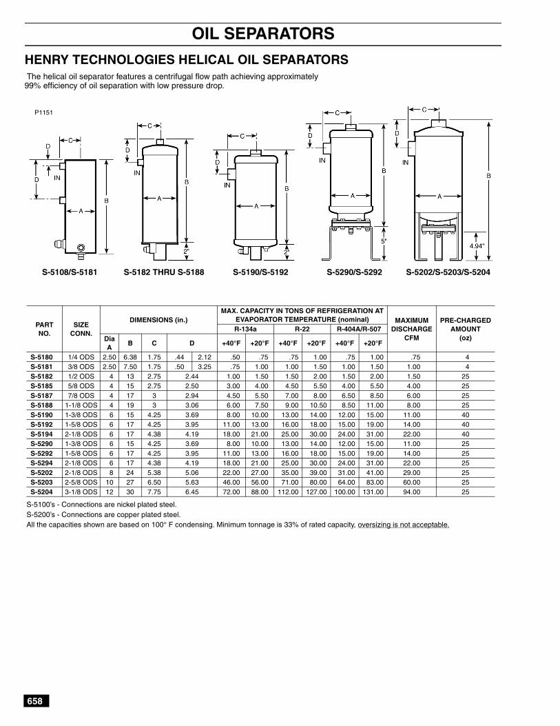
HENRY TECHNOLOGIES HELICAL OIL SEPARATORSThe helical oil separator features a centrifugal flow path achieving approximately99% efficiency of oil separation with low pressure drop.
S-5108/S-5181 S-5202/S-5203/S-5204S-5290/S-5292S-5190/S-5192S-5182 THRU S-5188
P1151
S-5100’s - Connections are nickel plated steel.S-5200’s - Connections are copper plated steel.All the capacities shown are based on 100° F condensing. Minimum tonnage is 33% of rated capacity, oversizing is not acceptable.
PARTNO.
SIZECONN.
DIMENSIONS (in.)MAX. CAPACITY IN TONS OF REFRIGERATION AT
EVAPORATOR TEMPERATURE (nominal) MAXIMUMDISCHARGE
CFM
PRE-CHARGEDAMOUNT
(oz)R-134a R-22 R-404A/R-507
DiaA
B C D +40°F +20°F +40°F +20°F +40°F +20°F
S-5180 1/4 ODS 2.50 6.38 1.75 .44 2.12 .50 .75 .75 1.00 .75 1.00 .75 4S-5181 3/8 ODS 2.50 7.50 1.75 .50 3.25 .75 1.00 1.00 1.50 1.00 1.50 1.00 4S-5182 1/2 ODS 4 13 2.75 2.44 1.00 1.50 1.50 2.00 1.50 2.00 1.50 25S-5185 5/8 ODS 4 15 2.75 2.50 3.00 4.00 4.50 5.50 4.00 5.50 4.00 25S-5187 7/8 ODS 4 17 3 2.94 4.50 5.50 7.00 8.00 6.50 8.50 6.00 25S-5188 1-1/8 ODS 4 19 3 3.06 6.00 7.50 9.00 10.50 8.50 11.00 8.00 25S-5190 1-3/8 ODS 6 15 4.25 3.69 8.00 10.00 13.00 14.00 12.00 15.00 11.00 40S-5192 1-5/8 ODS 6 17 4.25 3.95 11.00 13.00 16.00 18.00 15.00 19.00 14.00 40S-5194 2-1/8 ODS 6 17 4.38 4.19 18.00 21.00 25.00 30.00 24.00 31.00 22.00 40S-5290 1-3/8 ODS 6 15 4.25 3.69 8.00 10.00 13.00 14.00 12.00 15.00 11.00 25S-5292 1-5/8 ODS 6 17 4.25 3.95 11.00 13.00 16.00 18.00 15.00 19.00 14.00 25S-5294 2-1/8 ODS 6 17 4.38 4.19 18.00 21.00 25.00 30.00 24.00 31.00 22.00 25S-5202 2-1/8 ODS 8 24 5.38 5.06 22.00 27.00 35.00 39.00 31.00 41.00 29.00 25S-5203 2-5/8 ODS 10 27 6.50 5.63 46.00 56.00 71.00 80.00 64.00 83.00 60.00 25S-5204 3-1/8 ODS 12 30 7.75 6.45 72.00 88.00 112.00 127.00 100.00 131.00 94.00 25
659
OIL SEPARATORS
HENRY TECHNOLOGIES CONVENTIONAL OIL SEPARATORS
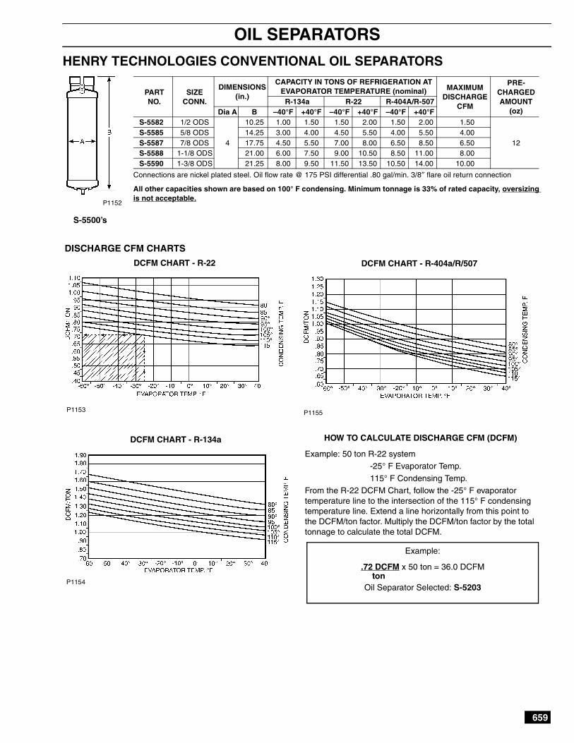
HOW TO CALCULATE DISCHARGE CFM (DCFM)
Example: 50 ton R-22 system-25° F Evaporator Temp.
115° F Condensing Temp.From the R-22 DCFM Chart, follow the -25° F evaporatortemperature line to the intersection of the 115° F condensingtemperature line. Extend a line horizontally from this point tothe DCFM/ton factor. Multiply the DCFM/ton factor by the totaltonnage to calculate the total DCFM.
DISCHARGE CFM CHARTS
DCFM CHART - R-22
Connections are nickel plated steel. Oil flow rate @ 175 PSI differential .80 gal/min. 3/8″ flare oil return connection
All other capacities shown are based on 100° F condensing. Minimum tonnage is 33% of rated capacity, oversizingis not acceptable.
PARTNO.
SIZECONN.
DIMENSIONS(in.)
CAPACITY IN TONS OF REFRIGERATION ATEVAPORATOR TEMPERATURE (nominal) MAXIMUM
DISCHARGECFM
PRE-CHARGEDAMOUNT
(oz)R-134a R-22 R-404A/R-507
Dia A B –40°F +40°F –40°F +40°F –40°F +40°FS-5582 1/2 ODS
4
10.25 1.00 1.50 1.50 2.00 1.50 2.00 1.50
12S-5585 5/8 ODS 14.25 3.00 4.00 4.50 5.50 4.00 5.50 4.00S-5587 7/8 ODS 17.75 4.50 5.50 7.00 8.00 6.50 8.50 6.50S-5588 1-1/8 ODS 21.00 6.00 7.50 9.00 10.50 8.50 11.00 8.00S-5590 1-3/8 ODS 21.25 8.00 9.50 11.50 13.50 10.50 14.00 10.00
S-5500’s
P1152
DCFM CHART - R-404a/R/507
DCFM CHART - R-134a
P1153 P1155
P1154
Example:
.72 DCFM x 50 ton = 36.0 DCFM
Oil Separator Selected: S-5203ton
660
OIL SEPARATOR ACCESSORIES
HENRY TECHNOLOGIES HEAT ELEMENTS
OIL SEPARATORS
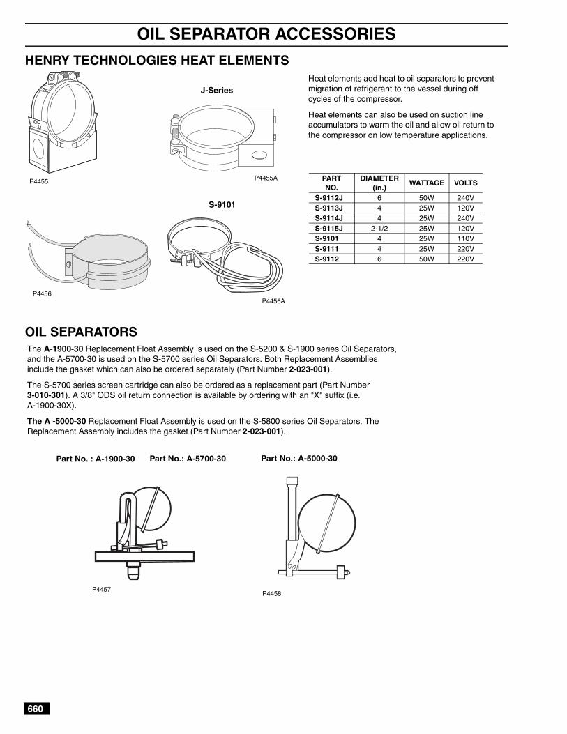
Heat elements add heat to oil separators to preventmigration of refrigerant to the vessel during offcycles of the compressor.
Heat elements can also be used on suction lineaccumulators to warm the oil and allow oil return tothe compressor on low temperature applications.
PARTNO.
DIAMETER(in.)
WATTAGE VOLTS
S-9112J 6 50W 240VS-9113J 4 25W 120VS-9114J 4 25W 240VS-9115J 2-1/2 25W 120VS-9101 4 25W 110VS-9111 4 25W 220VS-9112 6 50W 220V
P4455
P4456
P4455A
P4456A
J-Series
S-9101
The A-1900-30 Replacement Float Assembly is used on the S-5200 & S-1900 series Oil Separators,and the A-5700-30 is used on the S-5700 series Oil Separators. Both Replacement Assembliesinclude the gasket which can also be ordered separately (Part Number 2-023-001).
The S-5700 series screen cartridge can also be ordered as a replacement part (Part Number3-010-301). A 3/8" ODS oil return connection is available by ordering with an "X" suffix (i.e.A-1900-30X).
The A -5000-30 Replacement Float Assembly is used on the S-5800 series Oil Separators. TheReplacement Assembly includes the gasket (Part Number 2-023-001).
P4457P4458
Part No. : A-1900-30 Part No.: A-5700-30 Part No.: A-5000-30

661
OIL LEVEL REGULATORS (CONVENTIONAL)
HENRY TECHNOLOGIES OIL LEVEL REGULATORS
EQUALIZATIONCONN. 3/8" FLARE
OIL LINE CONN.3/8" FLARE
1/8 IN.
EQUALIZATIONCONN. 3/8" FLARE
OIL LINE CONN.3/8" FLARE
ADJUSTMENTSCREW
The oil level regulator controls the oil level in the compressorcrankcase with a float operated valve.
Oil level regulators are designed to attach directly to the sightglass housing on compressor crankcases. Adapter kits are
available for compressors that have a different sight glass con-figuration. The sight glass from the compressor or suppliedwith an adapter kit, bolts to the second regulator flange forvisual observation of the oil level.
S-9010 FIXED LEVEL REGULATORThe S-9010 regulator maintains the oil level in the compressor crankcase at1/8-in. sight glass. The S-9010 maintains the level at any pressure differential*between 5 and 30 psi.The S-9010 oil level regulator is designed to bolt directly to the 3 bolt sight glasshousing found on many compressor crankcases.Do not use on Satellite Compressor.
Part No.: S-9010
S-9090 ADJUSTABLE REGULATOROne oil level regulator for all applicationsThe S-9090 regulator allows the oil level in the compressor crankcase to bemaintained at any level between 1/4 and 1/2 sight glass.The S-9090 maintains the level at any pressure differential* between 5 and 90psi. If the oil level in the crankcase is too high or too low, the level can beadjusted by turning the adjustment screw on top of the regulator. This can bedone while the system is in operation. Our exclusive design eliminates the needof shutting down the system and disconnecting the oil feed lines in order toadjust the regulator.
Part No.: S-9090
S-9130 ADJUSTABLE REGULATOR
The S-9130 regulator allows the oil level in the compressor crankcase to bemaintained at any level between 1/4 and 1/2 sight glass.
The S-9130 maintains the level at any pressure differential* between 5 and90 psi. If the oil level in the crankcase is too high or too low, the level can beadjusted by turning the adjustment screw on top of the regulator. This canbe done while the system is in operation. Our exclusive design eliminatesthe need of shutting down the system and disconnecting the oil feed lines inorder to adjust the regulator.
Part No.: S-9130
P1156
P1157
*Operating Pressure Differential — The differ-ence between the oil fed to the oil regulator andits compressor crankcase, where the regulator iscontrolling oil level.
EQUALIZATIONCONN. 3/8" FLARE
OIL LINE CONN.3/8" FLARE
ADJUSTMENTSCREW
P1158
662
OIL LEVEL REGULATORS (CONVENTIONAL)
HENRY TECHNOLOGIES ELECTRO-MECHANICAL OIL LEVEL REGULATORS
3" Dia
2.402.533.59
6.50
3.18
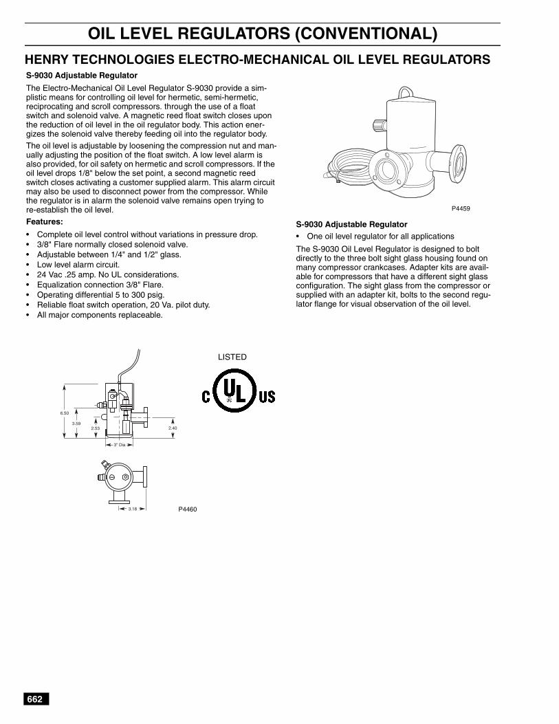
S-9030 Adjustable Regulator
The Electro-Mechanical Oil Level Regulator S-9030 provide a sim-plistic means for controlling oil level for hermetic, semi-hermetic,reciprocating and scroll compressors. through the use of a floatswitch and solenoid valve. A magnetic reed float switch closes uponthe reduction of oil level in the oil regulator body. This action ener-gizes the solenoid valve thereby feeding oil into the regulator body.The oil level is adjustable by loosening the compression nut and man-ually adjusting the position of the float switch. A low level alarm isalso provided, for oil safety on hermetic and scroll compressors. If theoil level drops 1/8" below the set point, a second magnetic reedswitch closes activating a customer supplied alarm. This alarm circuitmay also be used to disconnect power from the compressor. Whilethe regulator is in alarm the solenoid valve remains open trying tore-establish the oil level.Features:
• Complete oil level control without variations in pressure drop.• 3/8" Flare normally closed solenoid valve.• Adjustable between 1/4" and 1/2" glass.• Low level alarm circuit.• 24 Vac .25 amp. No UL considerations.• Equalization connection 3/8" Flare.• Operating differential 5 to 300 psig.• Reliable float switch operation, 20 Va. pilot duty.• All major components replaceable.
S-9030 Adjustable Regulator• One oil level regulator for all applications
The S-9030 Oil Level Regulator is designed to boltdirectly to the three bolt sight glass housing found onmany compressor crankcases. Adapter kits are avail-able for compressors that have a different sight glassconfiguration. The sight glass from the compressor orsupplied with an adapter kit, bolts to the second regu-lator flange for visual observation of the oil level.
P4459
P4460
LISTED
663
OIL RESERVOIRS
HENRY TECHNOLOGIES OIL RESERVOIR
C
B
B
AD
D AB
C
6" Dia
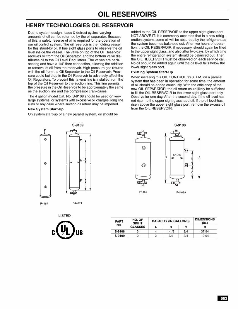
Due to system design, loads & defrost cycles, varyingamounts of oil can be returned by the oil separator. Becauseof this, a safety reserve of oil is required for the operation ofour oil control system. The oil reservoir is the holding vesselfor this stand-by oil. It has sight glass ports to observe the oillevel inside the vessel. The valve on top of the Oil Reservoirreceives oil from the Oil Separator, and the bottom valve dis-tributes oil to the Oil Level Regulators. The valves are back-seating and have a 1/4" flare connection, allowing the additionor removal of oil from the reservoir. High pressure gas returnswith the oil from the Oil Separator to the Oil Reservoir. Pres-sure could build up in the Oil Reservoir to adversely affect theOil Regulators. To prevent this, a vent line is installed from thetop of the Oil Reservoir to the suction line. This line permitsthe pressure in the Oil Reservoir to be approximately the sameas the suction line and the compressor crankcases.The 4 gallon model Cat. No. S-9108 should be used on verylarge systems, or systems with excessive oil charges, long lineruns or any case where suction oil return may be impeded.New System Start-UpOn system start-up of a new parallel system, oil should be
added to the OIL RESERVOIR to the upper sight glass port,NOT ABOVE IT. It is commonly accepted that in a new refrig-eration system, some oil will be absorbed by the refrigerant asthe system becomes balanced out. After two hours of opera-tion, the OIL RESERVOIR, if necessary, should again be filledto the upper sight glass, and also after two days, by which timethe entire refrigeration system should be balanced out. Thenthe OIL RESERVOIR must be observed on each service call.No oil should be added again until the oil level falls below thelower sight glass port.Existing System Start-UpWhen installing this OIL CONTROL SYSTEM, on a parallelsystem that has been in operation for some time, the amountof oil should be added cautiously. With the efficiency of thenew OIL SEPARATOR, the oil return could likely be sufficientto fill the OIL RESERVOIR to the lower sight glass port only.Observe for one day. After the second day, if the oil level hasnot risen to the upper sight glass, add oil. If the oil level hasrisen above the upper sight glass port, remove the excess oilfrom the OIL RESERVOIR.
PARTNO.
NO. OFSIGHT
GLASSES
CAPACITY (IN GALLONS) DIMENSIONS(in.)
A B C DS-9108 3 4 1-1/2 3/4 37.94S-9109 2 2 3/4 3/4 19.94
P4467
P4468 P4468A
P4467A
LISTED
S-9108S-9109
664
OIL LEVEL CONTROL ACCESSORIES
HENRY TECHNOLOGIES ELECTRONIC OIL LEVEL CONTROLAND ACCESSORIES
3 BOLT 1 7/8" B.C.
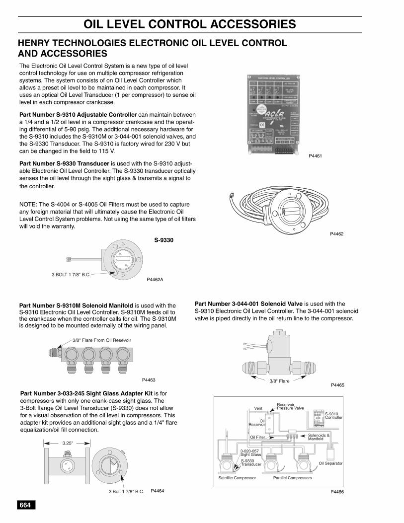
The Electronic Oil Level Control System is a new type of oil levelcontrol technology for use on multiple compressor refrigerationsystems. The system consists of on Oil Level Controller whichallows a preset oil level to be maintained in each compressor. Ituses an optical Oil Level Transducer (1 per compressor) to sense oillevel in each compressor crankcase.
Part Number S-9310 Adjustable Controller can maintain betweena 1/4 and a 1/2 oil level in a compressor crankcase and the operat-ing differential of 5-90 psig. The additional necessary hardware forthe S-9310 includes the S-9310M or 3-044-001 solenoid valves, andthe S-9330 Transducer. The S-9310 is factory wired for 230 V butcan be changed in the field to 115 V.
Part Number S-9330 Transducer is used with the S-9310 adjust-able Electronic Oil Level Controller. The S-9330 transducer opticallysenses the oil level through the sight glass & transmits a signal tothe controller.
NOTE: The S-4004 or S-4005 Oil Filters must be used to captureany foreign material that will ultimately cause the Electronic OilLevel Control System problems. Not using the same type of oil filterswill void the warranty.
P4461
P4462
P4462A
S-9330
3/8" Flare From Oil Resevoir
3.25"
3 Bolt 1 7/8" B.C.
3/8" Flare
ReservoirPressure Valve
S-9310Controller
Solenoids &Manifold
Oil Separator
Parallel CompressorsSatellite Compressor
S-9330Transducer
3-020-057Sight Glass
Oil Filter
OilReservoir
Vent
Part Number S-9310M Solenoid Manifold is used with theS-9310 Electronic Oil Level Controller. S-9310M feeds oil tothe crankcase when the controller calls for oil. The S-9310Mis designed to be mounted externally of the wiring panel.
P4463
P4464
P4465
P4466
Part Number 3-033-245 Sight Glass Adapter Kit is forcompressors with only one crank-case sight glass. The3-Bolt flange Oil Level Transducer (S-9330) does not allowfor a visual observation of the oil level in compressors. Thisadapter kit provides an additional sight glass and a 1/4" flareequalization/oil fill connection.
Part Number 3-044-001 Solenoid Valve is used with theS-9310 Electronic Oil Level Controller. The 3-044-001 solenoidvalve is piped directly in the oil return line to the compressor.
665
OIL LEVEL REGULATORS AND CONTROL ACCESSORIES
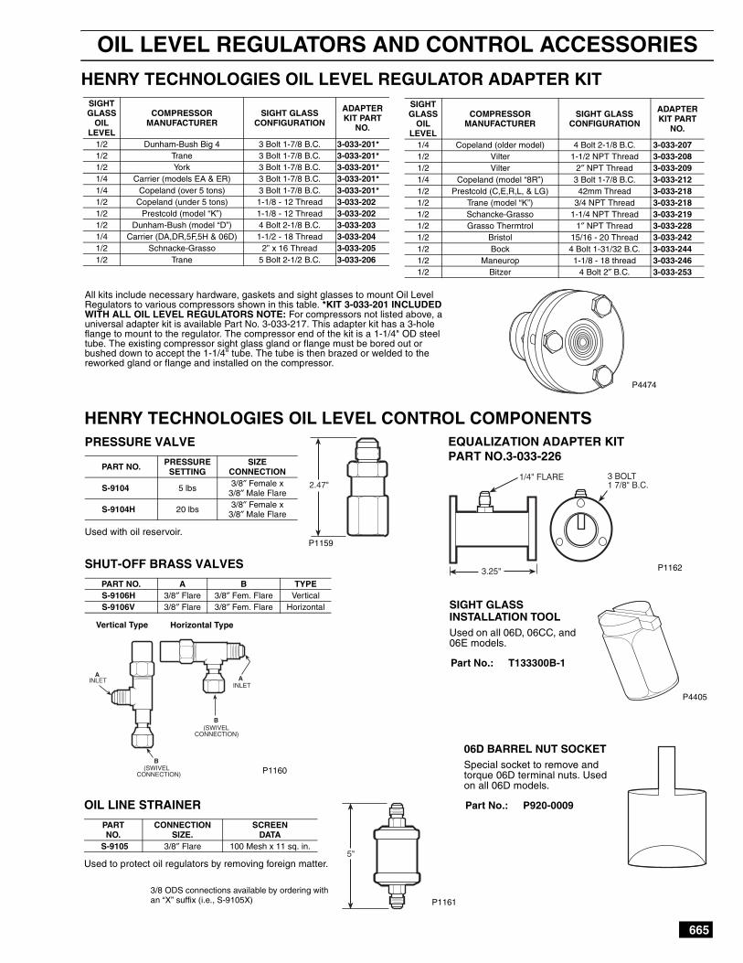
HENRY TECHNOLOGIES OIL LEVEL REGULATOR ADAPTER KITSIGHTGLASS
OILLEVEL
COMPRESSORMANUFACTURER
SIGHT GLASSCONFIGURATION
ADAPTERKIT PART
NO.
1/4 Copeland (older model) 4 Bolt 2-1/8 B.C. 3-033-2071/2 Vilter 1-1/2 NPT Thread 3-033-2081/2 Vilter 2″ NPT Thread 3-033-2091/4 Copeland (model “8R”) 3 Bolt 1-7/8 B.C. 3-033-2121/2 Prestcold (C,E,R,L, & LG) 42mm Thread 3-033-2181/2 Trane (model “K”) 3/4 NPT Thread 3-033-2181/2 Schancke-Grasso 1-1/4 NPT Thread 3-033-2191/2 Grasso Thermtrol 1″ NPT Thread 3-033-2281/2 Bristol 15/16 - 20 Thread 3-033-2421/2 Bock 4 Bolt 1-31/32 B.C. 3-033-2441/2 Maneurop 1-1/8 - 18 thread 3-033-2461/2 Bitzer 4 Bolt 2″ B.C. 3-033-253
SIGHTGLASS
OILLEVEL
COMPRESSORMANUFACTURER
SIGHT GLASSCONFIGURATION
ADAPTERKIT PART
NO.
1/2 Dunham-Bush Big 4 3 Bolt 1-7/8 B.C. 3-033-201*1/2 Trane 3 Bolt 1-7/8 B.C. 3-033-201*1/2 York 3 Bolt 1-7/8 B.C. 3-033-201*1/4 Carrier (models EA & ER) 3 Bolt 1-7/8 B.C. 3-033-201*1/4 Copeland (over 5 tons) 3 Bolt 1-7/8 B.C. 3-033-201*1/2 Copeland (under 5 tons) 1-1/8 - 12 Thread 3-033-2021/2 Prestcold (model “K”) 1-1/8 - 12 Thread 3-033-2021/2 Dunham-Bush (model “D”) 4 Bolt 2-1/8 B.C. 3-033-2031/4 Carrier (DA,DR,5F,5H & 06D) 1-1/2 - 18 Thread 3-033-2041/2 Schnacke-Grasso 2” x 16 Thread 3-033-2051/2 Trane 5 Bolt 2-1/2 B.C. 3-033-206
PRESSURE VALVE
Used with oil reservoir.
PART NO. PRESSURESETTING
SIZECONNECTION
S-9104 5 lbs 3/8″ Female x3/8″ Male Flare
S-9104H 20 lbs 3/8″ Female x3/8″ Male Flare
OIL LINE STRAINER
Used to protect oil regulators by removing foreign matter.
PARTNO.
CONNECTIONSIZE.
SCREENDATA
S-9105 3/8″ Flare 100 Mesh x 11 sq. in.
SHUT-OFF BRASS VALVES
PART NO. A B TYPES-9106H 3/8″ Flare 3/8″ Fem. Flare VerticalS-9106V 3/8″ Flare 3/8″ Fem. Flare Horizontal
EQUALIZATION ADAPTER KITPART NO.3-033-226
2.47"
5"
1/4" FLARE
3.25"
3 BOLT1 7/8" B.C.
P1160
P1159
B
AA
INLETINLET
(SWIVELCONNECTION)
B(SWIVEL
CONNECTION)
Horizontal TypeVertical Type
P4405
SIGHT GLASSINSTALLATION TOOLUsed on all 06D, 06CC, and06E models.
Part No.: T133300B-1
06D BARREL NUT SOCKETSpecial socket to remove andtorque 06D terminal nuts. Usedon all 06D models.
Part No.: P920-0009
HENRY TECHNOLOGIES OIL LEVEL CONTROL COMPONENTS
P1162
3/8 ODS connections available by ordering withan “X” suffix (i.e., S-9105X) P1161
All kits include necessary hardware, gaskets and sight glasses to mount Oil LevelRegulators to various compressors shown in this table. *KIT 3-033-201 INCLUDEDWITH ALL OIL LEVEL REGULATORS NOTE: For compressors not listed above, auniversal adapter kit is available Part No. 3-033-217. This adapter kit has a 3-holeflange to mount to the regulator. The compressor end of the kit is a 1-1/4" OD steeltube. The existing compressor sight glass gland or flange must be bored out orbushed down to accept the 1-1/4" tube. The tube is then brazed or welded to thereworked gland or flange and installed on the compressor.
P4474
666
REFRIGERATION OIL FILTER DRIERS
HENRY TECHNOLOGIES OIL FILTER — POE OIL FILTER-DRIER
3/8"Flare
7 3/8"
3/8"Flare
4"
New POEOil Filter& Drier
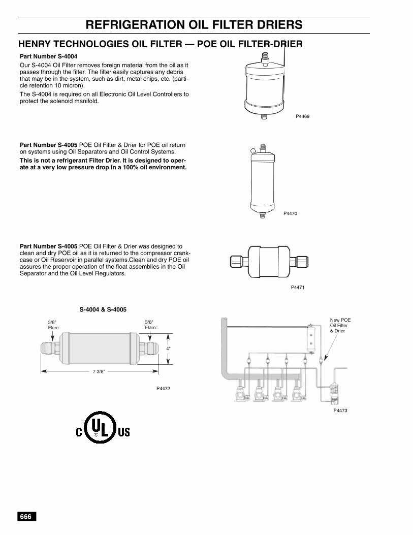
Part Number S-4004Our S-4004 Oil Filter removes foreign material from the oil as itpasses through the filter. The filter easily captures any debristhat may be in the system, such as dirt, metal chips, etc. (parti-cle retention 10 micron).The S-4004 is required on all Electronic Oil Level Controllers toprotect the solenoid manifold.
Part Number S-4005 POE Oil Filter & Drier for POE oil returnon systems using Oil Separators and Oil Control Systems.This is not a refrigerant Filter Drier. It is designed to oper-ate at a very low pressure drop in a 100% oil environment.
Part Number S-4005 POE Oil Filter & Drier was designed toclean and dry POE oil as it is returned to the compressor crank-case or Oil Reservoir in parallel systems.Clean and dry POE oilassures the proper operation of the float assemblies in the OilSeparator and the Oil Level Regulators.
P4469
P4470
P4471
P4473
P4472
S-4004 & S-4005
667
CHECK VALVES
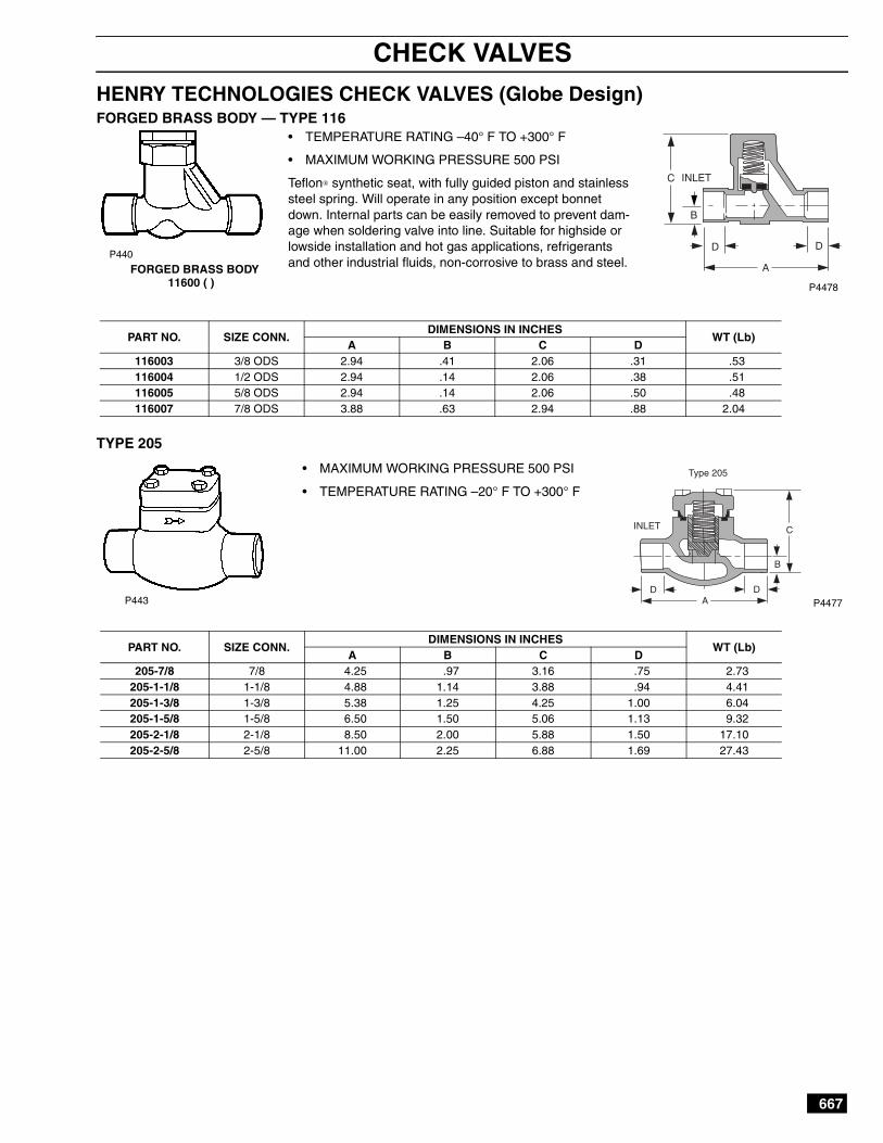
HENRY TECHNOLOGIES CHECK VALVES (Globe Design)FORGED BRASS BODY — TYPE 116
TYPE 205
• TEMPERATURE RATING –40° F TO +300° F
• MAXIMUM WORKING PRESSURE 500 PSI
Teflon synthetic seat, with fully guided piston and stainlesssteel spring. Will operate in any position except bonnetdown. Internal parts can be easily removed to prevent dam-age when soldering valve into line. Suitable for highside orlowside installation and hot gas applications, refrigerantsand other industrial fluids, non-corrosive to brass and steel.FORGED BRASS BODY
11600 ( )
PART NO. SIZE CONN.DIMENSIONS IN INCHES
WT (Lb)A B C D
116003 3/8 ODS 2.94 .41 2.06 .31 .53116004 1/2 ODS 2.94 .14 2.06 .38 .51116005 5/8 ODS 2.94 .14 2.06 .50 .48116007 7/8 ODS 3.88 .63 2.94 .88 2.04
P440
P4478
C INLET
B
D D
A
P443 P4477
PART NO. SIZE CONN.DIMENSIONS IN INCHES
WT (Lb)A B C D
205-7/8 7/8 4.25 .97 3.16 .75 2.73205-1-1/8 1-1/8 4.88 1.14 3.88 .94 4.41205-1-3/8 1-3/8 5.38 1.25 4.25 1.00 6.04205-1-5/8 1-5/8 6.50 1.50 5.06 1.13 9.32205-2-1/8 2-1/8 8.50 2.00 5.88 1.50 17.10205-2-5/8 2-5/8 11.00 2.25 6.88 1.69 27.43
DA
D
B
CINLET
Type 205• MAXIMUM WORKING PRESSURE 500 PSI
• TEMPERATURE RATING –20° F TO +300° F
668
CHECK VALVES
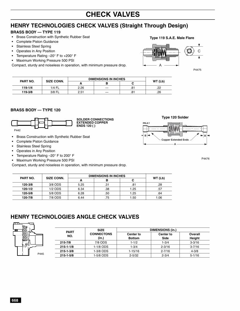
HENRY TECHNOLOGIES CHECK VALVES (Straight Through Design)BRASS BODY — TYPE 119
BRASS BODY — TYPE 120
HENRY TECHNOLOGIES ANGLE CHECK VALVES
• Brass Construction with Synthetic Rubber Seat• Complete Piston Guidance• Stainless Steel Spring• Operates in Any Position• Temperature Rating –20° F to +200° F• Maximum Working Pressure 500 PSICompact, sturdy and noiseless in operation, with minimum pressure drop.
Type 119 S.A.E. Male Flare
PART NO. SIZE CONN.DIMENSIONS IN INCHES
WT (Lb)A B C
119-1/4 1/4 FL 2.26 — .81 .22119-3/8 3/8 FL 2.51 — .81 .26
P4475
SOLDER CONNECTIONSEXTENDED COPPERENDS 120 ( )
P442
• Brass Construction with Synthetic Rubber Seat• Complete Piston Guidance• Stainless Steel Spring• Operates in Any Position• Temperature Rating –20° F to 200° F• Maximum Working Pressure 500 PSICompact, sturdy and noiseless in operation, with minimum pressure drop.
PART NO. SIZE CONN.DIMENSIONS IN INCHES
WT (Lb)A B C
120-3/8 3/8 ODS 5.25 .31 .81 .28120-1/2 1/2 ODS 6.34 .38 1.25 .57120-5/8 5/8 ODS 6.28 .50 1.25 .64120-7/8 7/8 ODS 6.44 .75 1.50 1.06
P4476
Type 120 Solder
PARTNO.
SIZECONNECTONS
(in.)
DIMENSIONS (in.)Center toBottom
Center toSide
OverallHeight
215-7/8 7/8 ODS 1-1/2 1-3/4 3-3/16215-1-1/8 1-1/8 ODS 1-3/4 2-3/16 3-7/16215-1-3/8 1-3/8 ODS 1-15/16 2-7/16 4-3/8215-1-5/8 1-5/8 ODS 2-5/32 2-3/4 5-1/16P445
669
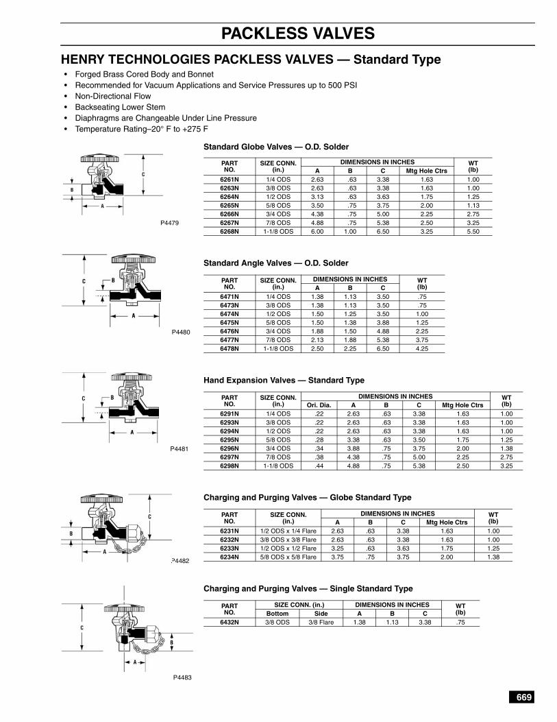
PACKLESS VALVES
HENRY TECHNOLOGIES PACKLESS VALVES — Standard Type
Standard Globe Valves — O.D. Solder
Standard Angle Valves — O.D. Solder
Hand Expansion Valves — Standard Type
Charging and Purging Valves — Globe Standard Type
Charging and Purging Valves — Single Standard Type
PARTNO.
SIZE CONN.(in.)
DIMENSIONS IN INCHES WT(lb)A B C Mtg Hole Ctrs
6261N 1/4 ODS 2.63 .63 3.38 1.63 1.006263N 3/8 ODS 2.63 .63 3.38 1.63 1.006264N 1/2 ODS 3.13 .63 3.63 1.75 1.256265N 5/8 ODS 3.50 .75 3.75 2.00 1.136266N 3/4 ODS 4.38 .75 5.00 2.25 2.756267N 7/8 ODS 4.88 .75 5.38 2.50 3.256268N 1-1/8 ODS 6.00 1.00 6.50 3.25 5.50
PARTNO.
SIZE CONN.(in.)
DIMENSIONS IN INCHES WT(lb)A B C
6471N 1/4 ODS 1.38 1.13 3.50 .756473N 3/8 ODS 1.38 1.13 3.50 .756474N 1/2 ODS 1.50 1.25 3.50 1.006475N 5/8 ODS 1.50 1.38 3.88 1.256476N 3/4 ODS 1.88 1.50 4.88 2.256477N 7/8 ODS 2.13 1.88 5.38 3.756478N 1-1/8 ODS 2.50 2.25 6.50 4.25
PARTNO.
SIZE CONN.(in.)
DIMENSIONS IN INCHES WT(lb)Ori. Dia. A B C Mtg Hole Ctrs
6291N 1/4 ODS .22 2.63 .63 3.38 1.63 1.006293N 3/8 ODS .22 2.63 .63 3.38 1.63 1.006294N 1/2 ODS .22 2.63 .63 3.38 1.63 1.006295N 5/8 ODS .28 3.38 .63 3.50 1.75 1.256296N 3/4 ODS .34 3.88 .75 3.75 2.00 1.386297N 7/8 ODS .38 4.38 .75 5.00 2.25 2.756298N 1-1/8 ODS .44 4.88 .75 5.38 2.50 3.25
PARTNO.
SIZE CONN.(in.)
DIMENSIONS IN INCHES WT(lb)A B C Mtg Hole Ctrs
6231N 1/2 ODS x 1/4 Flare 2.63 .63 3.38 1.63 1.006232N 3/8 ODS x 3/8 Flare 2.63 .63 3.38 1.63 1.006233N 1/2 ODS x 1/2 Flare 3.25 .63 3.63 1.75 1.256234N 5/8 ODS x 5/8 Flare 3.75 .75 3.75 2.00 1.38
PARTNO.
SIZE CONN. (in.) DIMENSIONS IN INCHES WT(lb)Bottom Side A B C
6432N 3/8 ODS 3/8 Flare 1.38 1.13 3.38 .75
P4480
P4481
P4483
• Forged Brass Cored Body and Bonnet• Recommended for Vacuum Applications and Service Pressures up to 500 PSI• Non-Directional Flow• Backseating Lower Stem• Diaphragms are Changeable Under Line Pressure• Temperature Rating–20° F to +275 F
P4479
P4482
670
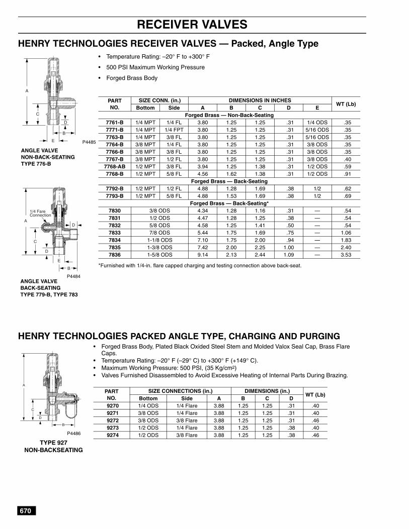
RECEIVER VALVES
HENRY TECHNOLOGIES RECEIVER VALVES — Packed, Angle Type
HENRY TECHNOLOGIES PACKED ANGLE TYPE, CHARGING AND PURGING
• Temperature Rating: –20° F to +300° F
• 500 PSI Maximum Working Pressure
• Forged Brass Body
*Furnished with 1/4-in. flare capped charging and testing connection above back-seat.
PARTNO.
SIZE CONN. (in.) DIMENSIONS IN INCHESWT (Lb)
Bottom Side A B C D EForged Brass — Non-Back-Seating
7761-B 1/4 MPT 1/4 FL 3.80 1.25 1.25 .31 1/4 ODS .357771-B 1/4 MPT 1/4 FPT 3.80 1.25 1.25 .31 5/16 ODS .357763-B 1/4 MPT 3/8 FL 3.80 1.25 1.25 .31 5/16 ODS .357764-B 3/8 MPT 1/4 FL 3.80 1.25 1.25 .31 3/8 ODS .357766-B 3/8 MPT 3/8 FL 3.80 1.25 1.25 .31 3/8 ODS .357767-B 3/8 MPT 1/2 FL 3.80 1.25 1.25 .31 3/8 ODS .40
7768-AB 1/2 MPT 3/8 FL 3.94 1.25 1.38 .31 1/2 ODS .597768-B 1/2 MPT 5/8 FL 4.56 1.62 1.38 .31 1/2 ODS .91
Forged Brass — Back-Seating7792-B 1/2 MPT 1/2 FL 4.88 1.28 1.69 .38 1/2 .627793-B 1/2 MPT 5/8 FL 4.88 1.53 1.69 .38 1/2 .69
Forged Brass — Back-Seating*7830 3/8 ODS 4.34 1.28 1.16 .31 — .547831 1/2 ODS 4.47 1.28 1.25 .38 — .547832 5/8 ODS 4.58 1.25 1.41 .50 — .547833 7/8 ODS 5.44 1.75 1.69 .75 — 1.067834 1-1/8 ODS 7.10 1.75 2.00 .94 — 1.837835 1-3/8 ODS 7.42 2.00 2.25 1.00 — 2.407836 1-5/8 ODS 9.14 2.13 2.44 1.09 — 3.53
ANGLE VALVEBACK-SEATINGTYPE 779-B, TYPE 783
ANGLE VALVENON-BACK-SEATINGTYPE 776-B
P4485
P4484
A
C
D
E
B
A
C
D
E
B
D
1/4 FareConnection
• Forged Brass Body, Plated Black Oxided Steel Stem and Molded Valox Seal Cap, Brass FlareCaps.
• Temperature Rating: –20° F (–29° C) to +300° F (+149° C).• Maximum Working Pressure: 500 PSI, (35 Kg/cm2)• Valves Furnished Disassembled to Avoid Excessive Heating of Internal Parts During Brazing.
PARTNO.
SIZE CONNECTIONS (in.) DIMENSIONS (in.)WT (Lb)
Bottom Side A B C D9270 1/4 ODS 1/4 Flare 3.88 1.25 1.25 .31 .409271 3/8 ODS 1/4 Flare 3.88 1.25 1.25 .31 .409272 3/8 ODS 3/8 Flare 3.88 1.25 1.25 .31 .469273 1/2 ODS 1/4 Flare 3.88 1.25 1.25 .38 .409274 1/2 ODS 3/8 Flare 3.88 1.25 1.25 .38 .46P4486
TYPE 927NON-BACKSEATING
A
C
D
B
671
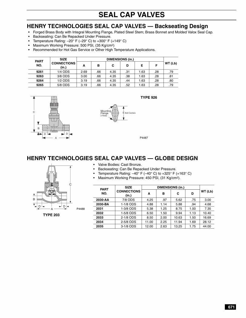
SEAL CAP VALVES
HENRY TECHNOLOGIES SEAL CAP VALVES — Backseating Design
HENRY TECHNOLOGIES SEAL CAP VALVES — GLOBE DESIGN
• Forged Brass Body with Integral Mounting Flange, Plated Steel Stem; Brass Bonnet and Molded Valox Seal Cap.• Backseating: Can Be Repacked Under Pressure.• Temperature Rating: –20° F (–29° C) to +300° F (+149° C)• Maximum Working Pressure: 500 PSI, (35 Kg/cm2)• Recommended for Hot Gas Service or Other High Temperature Applications.
PARTNO.
SIZECONNECTIONS
(in.)
DIMENSIONS (in.)WT (Lb)
A B C D E F
9261 1/4 ODS 2.69 .66 4.35 .31 1.63 .28 .799263 3/8 ODS 3.00 .66 4.35 .38 1.63 .28 .819264 1/2 ODS 3.19 .66 4.35 .44 1.63 .28 .809265 5/8 ODS 3.19 .66 4.35 .52 1.63 .28 .79
P4487
TYPE 926
E Bolt CentersMountingFlange2 Holes
C
B
D D
A
P4488
• Valve Bodies: Cast Bronze.• Backseating: Can Be Repacked Under Pressure.• Temperature Rating: –40° F (–40° C) to +325° F (+163° C)• Maximum Working Pressure: 450 PSI, (31 Kg/cm2).
PARTNO.
SIZECONNECTIONS
(in.)
DIMENSIONS (in.)WT (Lb)
A B C D
2030-AA 7/8 ODS 4.25 .97 5.62 .75 3.002030-BA 1-1/8 ODS 4.88 1.14 5.88 .94 4.682031 1-3/8 ODS 5.38 1.25 8.75 1.00 7.352032 1-5/8 ODS 6.50 1.50 9.94 1.13 10.402033 2-1/8 ODS 8.50 2.00 10.63 1.50 16.692034 2-5/8 ODS 11.00 2.25 11.94 1.69 28.122035 3-1/8 ODS 12.00 2.63 13.25 1.75 44.00
TYPE 203
C
DDA
B
672
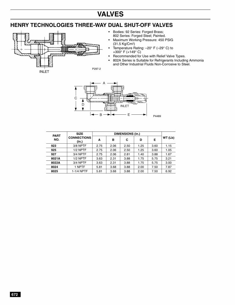
VALVES
HENRY TECHNOLOGIES THREE-WAY DUAL SHUT-OFF VALVES
C
D
B E
A
INLET
• Bodies: 92 Series: Forged Brass;802 Series: Forged Steel; Painted.
• Maximum Working Pressure: 450 PSIG(31.5 Kg/Cm2)
• Temperature Rating: –20° F (–29° C) to+300° F (+149° C)
• Recommended for Use with Relief Valve Types.• 802A Series is Suitable for Refrigerants Including Ammonia
and Other Industrial Fluids Non-Corrosive to Steel.
INLETP297-2
PARTNO.
SIZECONNECTIONS
(in.)
DIMENSIONS (in.)WT (Lb)
A B C D E
923 3/8 NPTF 2.75 2.06 2.50 1.25 3.60 1.15925 1/2 NPTF 2.75 2.06 2.50 1.25 3.60 1.05927 3/4 NPTF 2.75 2.06 2.81 1.40 3.88 1.678021A 1/2 NPTF 3.63 2.31 3.88 1.75 5.75 3.218022A 3/4 NPTF 3.63 2.31 3.88 1.75 5.75 3.008024 1 NPTF 5.81 3.68 3.88 2.00 7.50 7.878025 1-1/4 NPTF 5.81 3.68 3.88 2.00 7.50 6.92
P4489

673
PRESSURE RELIEF VALVES
HENRY TECHNOLOGIES PRESSURE RELIEF VALVES — Atmospheric,Angle & Straight-Thru Types• Brass Construction Set and Sealed at the Factory; All
NPTF Connections are American Standard DrysealTapered Pipe Threads
• Valves are Stamped with Catalog Number, Size, PressureSetting, Capacity and ASME-UV National Board Symbol;CRN Number and Flow Arrow
• All NPTF Connections are American Standard DrysealTapered Pipe Threads
• Positive Pressure Relief• Suitable for Refrigerants 12, 22, 500, 502, 12, 134a, and
Other Industrial Fluids Non-Corrosive to Brass, Monel,Steel and Teflon
• Temperature Rating: –40° F (–40° C) to +225° F (+107° C)• Orders Must Specify Catalog Number, Pressure Setting,
and Type of Refrigerant or Fluid With Which the Valve is tobe Used; UV/NB Certified Setting Range 150-450 PSI.Contact Henry for Non-Certified Setting Range Information.
• Standard Settings Are: 235 PSI, 300 PSI, 350 PSI,400 PSI, 425 PSI, 450 PSI
• IMPORTANT: ORDERS MUST SPECIFY PRESSURESETTING. RANGE 150 to 450 PSI
P4490
P4491
P4492
ASME NBNationalBoardCertified
ATMOSPHERIC RELIEF VALVES
ANGLE RELIEF VALVES
STRAIGHT-THRU RELIEF VALVES
RELIEF VALVE CAPACITY RATINGS
PARTNO.
SIZE CONN.INLET
DIM/IN.A
ORIFICEDIA.
WT(lb)
5221 1/4 MPT 2.50 .19 .335223 3/8 MPT 2.50 .19 .37
PARTNO.
SIZE CONN. DIM./IN. ORIFICEDIA.
WT(lb)Inlet Outlet A B
526E 3/8 MPT 3/8 FL 2.96 1.41 .25 .60527E 1/2 MPT 5/8 FL 3.81 1.72 .44 1.25
PARTNO.
SIZE CONN. DIM./IN. ORIFICEDIA.
WT(lb)Inlet Outlet A
5230 1/4 MPT 3/8 FL 3.16 .25 .385231 3/8 MPT 3/8 FL 3.16 .25 .39
5231-A 3/8 MPT 1/2 FL 3.28 .25 .415232 1/2 MPT 5/8 FL 4.00 .44 .85
5240-1/2 1/2 MPT 3/4 FPT 3.74 .38 .955242-3/4 3/4 MPT 3/4 FPT 3.74 .38 1.035244-1 1 MPT 1 FPT 4.16 .50 1.46
PARTNO.
STANDARD PRESSURE SETTING (psig)300 350 400 425 450
5221 7.3 8.4 9.6 10.2 10.75223526E
9.6 11.2 12.7 13.5 14.352305231
5231-A 16.0 18.6 21.1 22.4 23.75232 24.2 28.1 32.0 33.9 35.8527E
5240-1/2 35.5 41.2 46.8 49.1 52.55242-3/45244-1 63.8 74.0 84.2 89.3 94.4
A
INLET
A
INLET
B
A
INLET
Type 523 & 524Straight Thru
Type 522Atmospheric
Type 52 Angle
674
RUPTURE DISC ASSEMBLIES
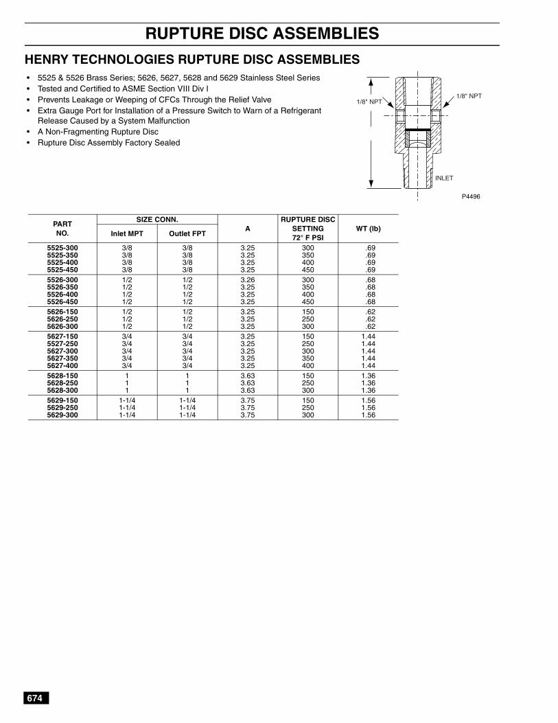
HENRY TECHNOLOGIES RUPTURE DISC ASSEMBLIES
PARTNO.
SIZE CONN.A
RUPTURE DISCSETTING72° F PSI
WT (lb)Inlet MPT Outlet FPT
5525-300 3/8 3/8 3.25 300 .695525-350 3/8 3/8 3.25 350 .695525-400 3/8 3/8 3.25 400 .695525-450 3/8 3/8 3.25 450 .695526-300 1/2 1/2 3.26 300 .685526-350 1/2 1/2 3.25 350 .685526-400 1/2 1/2 3.25 400 .685526-450 1/2 1/2 3.25 450 .685626-150 1/2 1/2 3.25 150 .625626-250 1/2 1/2 3.25 250 .625626-300 1/2 1/2 3.25 300 .625627-150 3/4 3/4 3.25 150 1.445527-250 3/4 3/4 3.25 250 1.445627-300 3/4 3/4 3.25 300 1.445627-350 3/4 3/4 3.25 350 1.445627-400 3/4 3/4 3.25 400 1.445628-150 1 1 3.63 150 1.365628-250 1 1 3.63 250 1.365628-300 1 1 3.63 300 1.365629-150 1-1/4 1-1/4 3.75 150 1.565629-250 1-1/4 1-1/4 3.75 250 1.565629-300 1-1/4 1-1/4 3.75 300 1.56
• 5525 & 5526 Brass Series; 5626, 5627, 5628 and 5629 Stainless Steel Series• Tested and Certified to ASME Section VIII Div I• Prevents Leakage or Weeping of CFCs Through the Relief Valve• Extra Gauge Port for Installation of a Pressure Switch to Warn of a Refrigerant
Release Caused by a System Malfunction• A Non-Fragmenting Rupture Disc• Rupture Disc Assembly Factory Sealed
1/8" NPT1/8" NPT
INLET
P4496

675
RUPTURE ASSEMBLY PRESSURE SWITCHES/INDICATORS
HENRY TECHNOLOGIES RUPTURE ASSEMBLY PRESSURE SWITCH
HENRY TECHNOLOGIES RUPTURE ASSEMBLY PRESSURE INDICATOR
• Type: Direct Action Blade Contact• Contacts: Silver Alloy, Gold Plated• Set Point: Factory Set and Sealed• Pressure Setting: 5 PSI• Switch Burst Pressure: 750 PSI• Ratings: 4 AMP - 24 VDC• Diaphragm: TEFLON• Temperature Range: –40°F to +250° F• Connector: 1/8-27 NPT Male Thread• Terminals: METRI-PACK, 1/4-in. Blade• Circuitry: Normally Opened• Base: Steel• Cover: Glass Reinforced Polyester• Furnished with METRI-PACK Connector and 10 ft of Wire
NOTES: The addition of a “Sentry” Pressure Switch provides an inexpensivemeans of providing an electrical signal to warn of a refrigerant release causedby a system malfunction. An extra gauge port is provided on the Sentry RuptureDisc Assembly for the switch.
P4497
P4497A
Pressure SwitchPart No.: SW56
3.0
1.5
• Dial: 1-3/8-in. (35 mm), White Aluminum Dial with Red Marking• Dial: Maximum Working Pressure: 600 PSI• Case: AISI 304 Stainless Steel• Lens: Plexiglass, Watertight• Pointer: AISI 304 Stainless Steel• Socket: AISI 304 Stainless Steel• Ambient Temperature: –40° F/+150° F (–40° C+65° C)
NOTES: The Pressure Indicator (Item A) can be used with our SentryRupture Disc Assembly (Item B), which helps prevent leakage of bothhalocarbon and ammonia refrigerants by indicating whether the reliefvalve had discharged.
The Sentry Rupture Disc Assembly, as required by ANSI/ASME Code,provides a chamber between the rupture disc and the relief valve, anda connection to install the new pressure indicator. This arrangementpermits a positive indication that the disc has ruptured and the reliefvalve has discharged.
Item A —Pressure Indicator G15
Item B
P4498A
PART NO.SIZE
CONNECTIONG15 1/8-in. MPT, Back
P4500
The “Sentry” Rupture Disc Assembly/Relief Valve Combination isshown in its Normal operating condition with System Pressure onlyunder the Rupture Disc. (See first pressure gauge.)
NOTE: Relief valve, pressure gauge and pipe plug not included with“Sentry” Rupture Disc Assembly.
USE NO OIL MAXINPUT600 psi
USE NO OIL MAXINPUT600 psi
USENOOIL
MAXINPUT500 psi
USE NO OIL MAXINPUT600 psi
P4498 P4499

676
RUPTURE ASSEMBLY PRESSURE SWITCHES/INDICATORS
HENRY TECHNOLOGIES TRANSDUCER VALVE
P4501
• Forged Brass• Temperature Rating: –20° F (–29° C) to +300° F (+149° C)• Maximum Working Pressure: 500 PSI (35 kg/cm2)• Connector: 1/4-in. Flare Access with Schrader Core• Provides Access to Systems and Mounting of a Transducer to Monitor Systems
Performance• Provides Schrader Valve Port for Checking Transducer Output with a Pressure
Gauge• Provides Isolation from System for Replacement of Transducer• Suitable for Refrigerants and Other Industrial Fluids Non-Corrosive to Brass and
Steel
PARTNO.
SIZE CONN. DIMENSIONS IN INCHESWT (lb)
Side Bottom A B C D9290 1/8 FPT-1/4 FL 1/4 MPT 2.38 1.19 1.56 4.16 .52
D
C
B
A