Embed Size (px)
Citation preview

PEB3101 - Plastics Process Engineering Module 6 – Thermoforming Process & Rotational Molding
D. Murali Manohar / Asst Professor - Department of Polymer Engineering 1
Thermoforming Process
Thermoforming normally consists of heating a thermoplastic sheet until the forming
temperature (Basically the raw material is transformed by heating into a viscous - flexible phase) is reached and
forming the hot and flexible material against the contours of a mold by mechanical means
(e.g., tools, plugs, solid molds, etc.) or pneumatic means (e.g., differentials in air pressure
created by pulling a vacuum or using the pressures of compressed air). The formed part
cools in the tooling and is subsequently demolded. Due to cooling down, the orientations of
the molecule chains keep their stretched positions. Re - heating results in a recovery to the
original sheet state.
RAW MATERIALS
1. PC, PMMA, PA, POM, and ABS as well as fiber - reinforced composites and self -
reinforced materials are semifinished products for technical applications. For the
automobile industry, often thermoplastic elastomers and thermoplastic polyolefins
are used.
2. PET, PS, PP, PVC, and PE are semifinished products for packaging applications.
THERMOFORMING METHODS
The forming technologies are differentiated into the following subgroups:
• Positive
• Negative
a. Compressed air
b. Vacuum
c. Plug assisted
• Lamination
To some extent these methods can also be combined.
POSITIVE FORMING
In the positive forming method, the heated semifinished product (sheet) is drawn over the
forming mold. The definition is on the inside of the finished part. During the forming
process the inside has contact with the forming mold and takes over its shape.
In a first step, the thermoplastic semifinished product is brought to its forming
temperature. In order to receive a uniform wall thickness distribution, the material is pre -
streched by means of pre - blowing. After this, the mold closes, and vacuum is applied to
bring the material to its final shape. Demolding takes place after the plastic has cooled.
PEB3101 - Plastics Process Engineering Module 6 – Thermoforming Process & Rotational Molding
D. Murali Manohar / Asst Professor - Department of Polymer Engineering 2
NEGATIVE FORMING
A common application of negative forming is in the production of cups. After the heated
film has been positioned in the forming station, the mold closes. As the plug assist pulls
down, the trapped air in the cavity is released by means of venting holes. Then the forming
air is applied and the part receives its final shape. Demolding takes place after the plastic
has cooled down.
ADVANTAGES AND DISADVANTAGES OF THERMOFORMING
Thermoforming is mostly in concurrence with injection molding. The advantages and
disadvantages listed below principally refer to a comparison with injection molding.
The manufacturing of technical articles by forming has the following advantages:
• Heavy parts can be produced (up to 125 kg)
• Large parts can be manufactured (up to 4 m2 )
• Flexible wall thickness (0.05 – 16 mm)
• Cost - effectiveness for small batches (tooling costs)
• Low costs for modifications and for color change
• Homogeneous multilayer applications are possible
The manufacturing of packaging parts by forming has the following advantages:
• Shorter cycle times
• High output
• Processing of printed semifinished product is possible
• Processing of multilayered semifinished product is possible
The disadvantages of thermoforming are the following:
• Less scope for design (undercuts)
• No uniform distribution of wall thickness
• Temperature control is difficult
• For a given semifinished product, the manufacturer has no influence over the
formulation of the film, if dealing with purchased film.
THERMOFORMING PROCESSES
Vacuum Forming into a Female Mold
To vacuum form a thermoplastic sheet into a female mold without prestretching, the ratio
of depth to minor dimension of a given section should not be greater than 1 : 1, and no
sharp inside radii are required.
PEB3101 - Plastics Process Engineering Module 6 – Thermoforming Process & Rotational Molding
D. Murali Manohar / Asst Professor - Department of Polymer Engineering 3
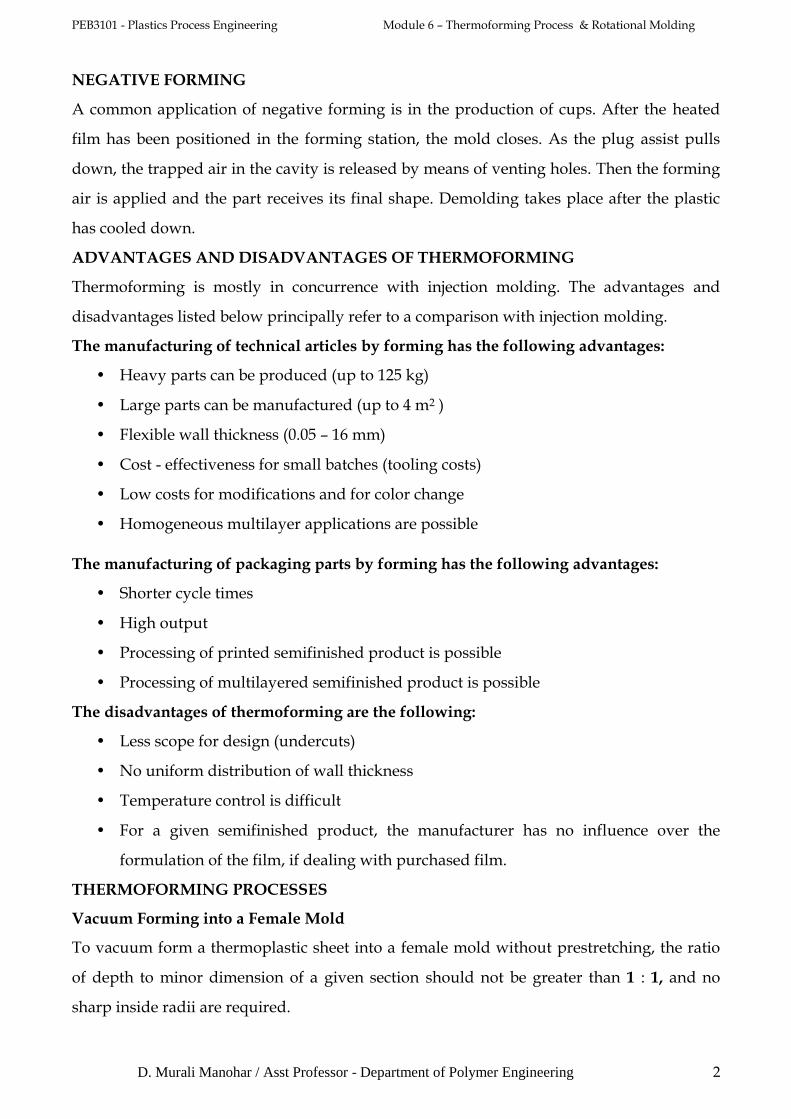
The process
The sheet stock is locked in a frame around its periphery only and is heated to a
predetermined temperature, and then it is brought into contact with the edge of the mold.
This contact should create a seal so that it is possible to remove the air between the hot
plastic and the mold, allowing atmospheric pressure to force the hot plastic against the
mold. Most thermoplastics sheets (with the exception of cast acrylic) can be easily formed
with vacuum.
The reasons for using a female mold are: greater details can be achieved on the outer
surface of the part; multiple cavities can be placed closer together; and this type is easier to
work with when close tolerances are needed on the outside of the part. However female
molds are more expensive to make than male molds.
PEB3101 - Plastics Process Engineering Module 6 – Thermoforming Process & Rotational Molding
D. Murali Manohar / Asst Professor - Department of Polymer Engineering 4
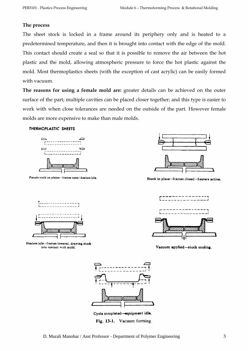
Pressure Forming into Female Cavity
Instead of relying on atmospheric pressure against a vacuum, positive air pressure (formed by
compressed air at up to 500 psi) is applied against the top of the sheet to force it into a female mold,
and, at the same time, full vacuum also is applied. As contrasted to vacuum forming,
pressure forming offers a faster production cycle (the sheet can be formed at a slightly
lower sheet temperature), greater part definition, and greater dimensional control.
Plug-Assist Forming
Straight cavity forming is not well adapted to forming a cup or box shape products. The
sheet, drawn down by vacuum, touches first along the side walls and then at the center of
the bottom of the box-shaped mold and starts to cool there, with its position and its
thickness becoming fixed. As the sheet continues to fill out the mold, solidification
continues in such a way as to use up most of the stock before it reaches the periphery of the
base; hence this part of the article will be relatively thin and weak. This characteristic is
undesirable in a cup shape, and usually unacceptable in a box shape, in which the thinness
will be most marked at the comers of the base. To promote uniformity of distribution in
such shapes, designers use the plug assist type of mechanical helper that carries extra stock
toward an area that otherwise would be too thin. Usually the plug is made of metal, and
heated to a temperature slightly below that of the hot plastic, so as not to cool the stock
before it can reach its final shape. Instead of metal, a smooth-grained hard wood can also be
used, or a felt-covered phenolic or epoxy; these materials are poor conductors of heat and
hence do not withdraw much heat from the sheet stock. Synthetic foam has been very
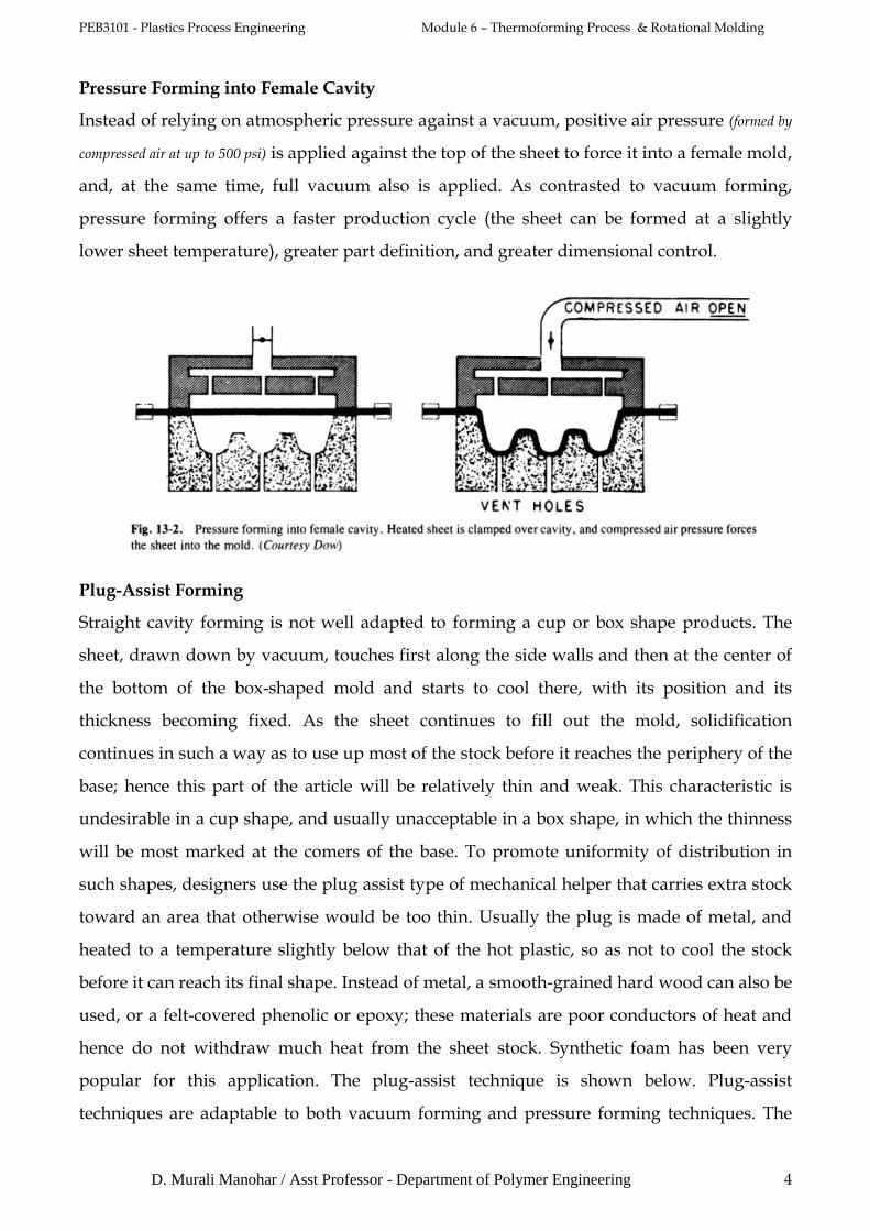
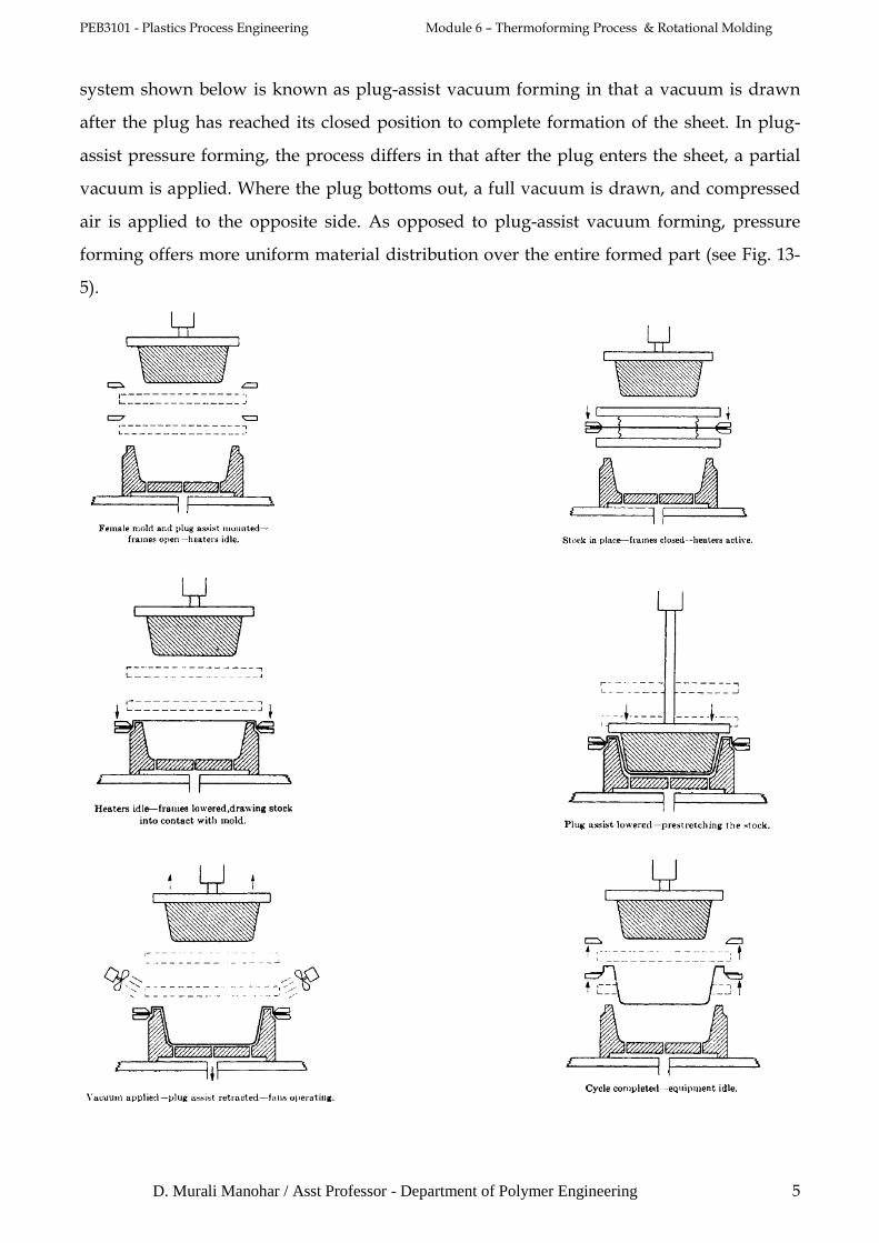
popular for this application. The plug-assist technique is shown below. Plug-assist
techniques are adaptable to both vacuum forming and pressure forming techniques. The
PEB3101 - Plastics Process Engineering Module 6 – Thermoforming Process & Rotational Molding
D. Murali Manohar / Asst Professor - Department of Polymer Engineering 5
system shown below is known as plug-assist vacuum forming in that a vacuum is drawn
after the plug has reached its closed position to complete formation of the sheet. In plug-
assist pressure forming, the process differs in that after the plug enters the sheet, a partial
vacuum is applied. Where the plug bottoms out, a full vacuum is drawn, and compressed
air is applied to the opposite side. As opposed to plug-assist vacuum forming, pressure
forming offers more uniform material distribution over the entire formed part (see Fig. 13-
5).

PEB3101 - Plastics Process Engineering Module 6 – Thermoforming Process & Rotational Molding
D. Murali Manohar / Asst Professor - Department of Polymer Engineering 6
Matched Mold Forming
This mechanical techniques that use neither air pressure nor vacuum is matched mold
forming ( below Fig.). In this operation, the plastic sheet is locked into the clamping frame
and heated to the proper forming temperature. A male mold is positioned on either the top
or the bottom platen with a matched female mold mounted on the other one. The mold
then is closed, forcing the plastic to the contours of both molds. The clearance between the
male and female molds determines the wall thickness. Trapped air is allowed to escape
through both mold faces. Molds are held in place until the plastic cools and cures. Matched
mold forming offers excellent reproduction of mold detail and dimensional accuracy.
Internal cooling of the mold is desirable in this technique.
Dual Sheet Forming
A number of techniques have been made available for the production of hollow products
by thermoforming. Typical is the concept of dual sheet thermoforming (also known as
twin-sheet forming). It operates as follows: Two rolls of plastic sheet are automatically fed,
PEB3101 - Plastics Process Engineering Module 6 – Thermoforming Process & Rotational Molding
D. Murali Manohar / Asst Professor - Department of Polymer Engineering 7
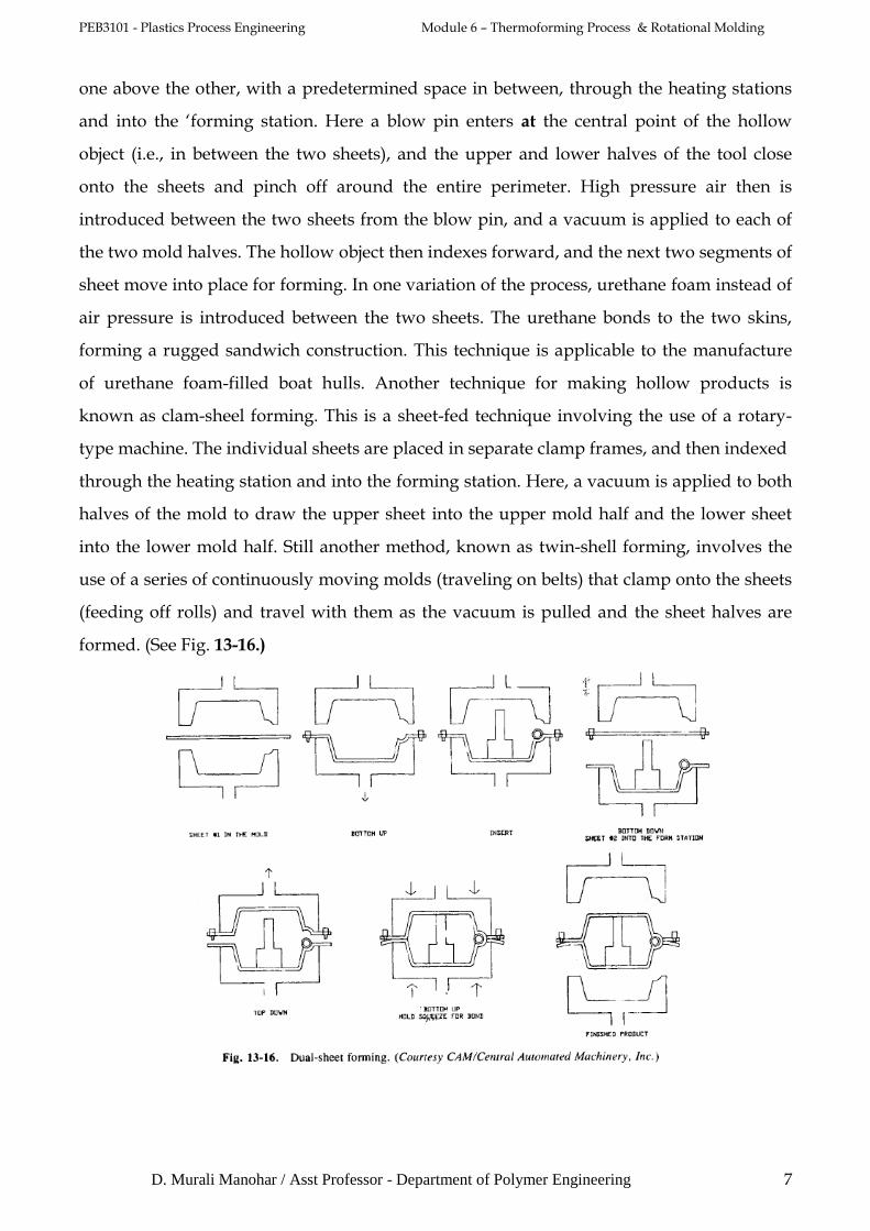
one above the other, with a predetermined space in between, through the heating stations
and into the ‘forming station. Here a blow pin enters at the central point of the hollow
object (i.e., in between the two sheets), and the upper and lower halves of the tool close
onto the sheets and pinch off around the entire perimeter. High pressure air then is
introduced between the two sheets from the blow pin, and a vacuum is applied to each of
the two mold halves. The hollow object then indexes forward, and the next two segments of
sheet move into place for forming. In one variation of the process, urethane foam instead of
air pressure is introduced between the two sheets. The urethane bonds to the two skins,
forming a rugged sandwich construction. This technique is applicable to the manufacture
of urethane foam-filled boat hulls. Another technique for making hollow products is
known as clam-sheel forming. This is a sheet-fed technique involving the use of a rotary-
type machine. The individual sheets are placed in separate clamp frames, and then indexed
through the heating station and into the forming station. Here, a vacuum is applied to both
halves of the mold to draw the upper sheet into the upper mold half and the lower sheet
into the lower mold half. Still another method, known as twin-shell forming, involves the
use of a series of continuously moving molds (traveling on belts) that clamp onto the sheets
(feeding off rolls) and travel with them as the vacuum is pulled and the sheet halves are
formed. (See Fig. 13-16.)
PEB3101 - Plastics Process Engineering Module 6 – Thermoforming Process & Rotational Molding
D. Murali Manohar / Asst Professor - Department of Polymer Engineering 8
Thermoforming Machinery
There are two general thermoforming categories.
1. Typically, heavy-gage sheet is handled as discrete cut sections and the forming
equipment are called cut-sheet thermoformers.
2. Thin-gage sheet is handled in continuous rolls and the forming equipment is usually
called roll-fed thermoformers.
The equipment in both categories includes:
1. Some form of sheet handling device,
2. A way of moving the sheet from one station to another,
3. A means of controlling the various elements that allow the sheet to be heated,
formed and moved from station to station,
4. A sheet heating oven,
5. A vacuum system,
6. A forming press, and
7. A formed part removal region.
In addition, the equipment may include:
1. Some form of prestretching such as:
a. preblowing or
b. plug assist,
2. A pressure system,
3. A trimming press, and
4. Some form of trim removal.
Machines often are classified according to the number of operations they perform.
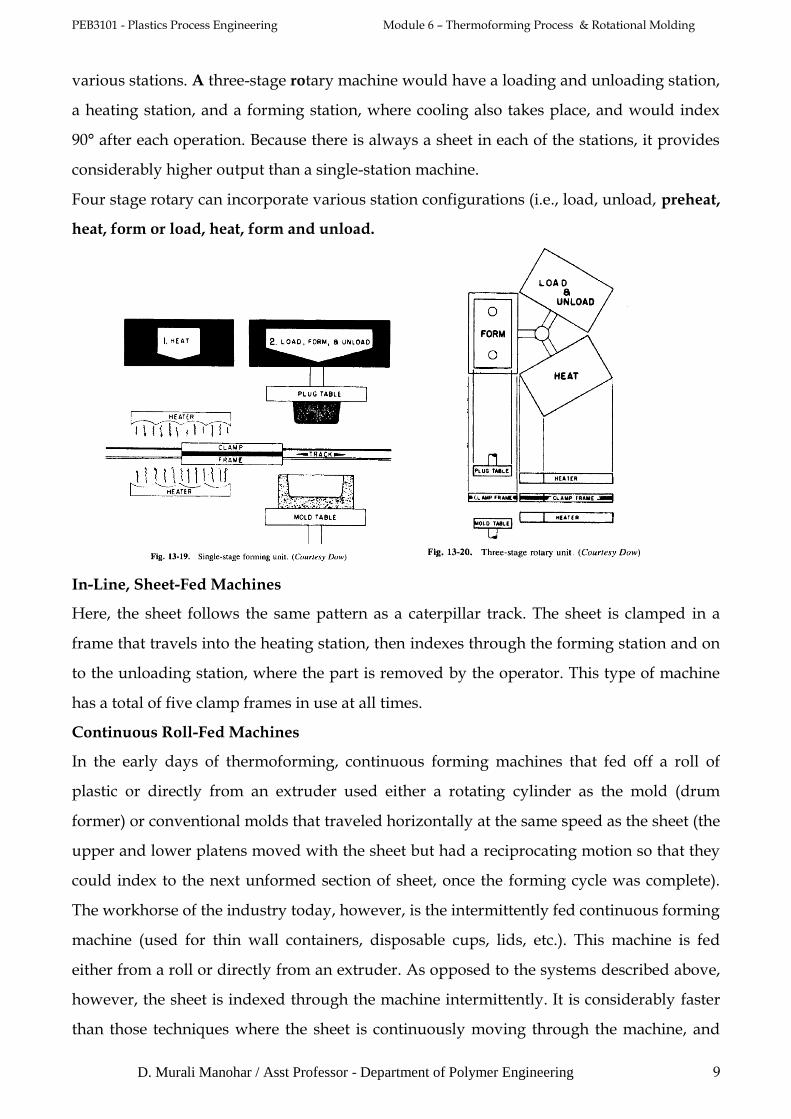
Single-Stage, Sheet-Fed Machines
A single-stage machine can perform only one operation at a time, and its total cycle will be
the sum of the times required for loading, heating, forming, cooling, and unloading. In a
typical operation, the sheet is clamped in a frame, and the frame is moved between the
heaters (or under a single heater) and back to the forming station for thermoforming.
Multiple-Stage, Sheet-Fed Machines
A two-stage machine can perform two operations simultaneously. It usually consists of two
forming stations and a bank of heaters that move from one station to the other. Machines
with three stages or more usually are built on a horizontal circular frame and are called
rotaries. The rotary thermoformer operates like a merry-go-round, indexing through the
PEB3101 - Plastics Process Engineering Module 6 – Thermoforming Process & Rotational Molding
D. Murali Manohar / Asst Professor - Department of Polymer Engineering 9
various stations. A three-stage rotary machine would have a loading and unloading station,
a heating station, and a forming station, where cooling also takes place, and would index
90° after each operation. Because there is always a sheet in each of the stations, it provides
considerably higher output than a single-station machine.
Four stage rotary can incorporate various station configurations (i.e., load, unload, preheat,
heat, form or load, heat, form and unload.
In-Line, Sheet-Fed Machines
Here, the sheet follows the same pattern as a caterpillar track. The sheet is clamped in a
frame that travels into the heating station, then indexes through the forming station and on
to the unloading station, where the part is removed by the operator. This type of machine
has a total of five clamp frames in use at all times.
Continuous Roll-Fed Machines
In the early days of thermoforming, continuous forming machines that fed off a roll of
plastic or directly from an extruder used either a rotating cylinder as the mold (drum
former) or conventional molds that traveled horizontally at the same speed as the sheet (the
upper and lower platens moved with the sheet but had a reciprocating motion so that they
could index to the next unformed section of sheet, once the forming cycle was complete).
The workhorse of the industry today, however, is the intermittently fed continuous forming
machine (used for thin wall containers, disposable cups, lids, etc.). This machine is fed
either from a roll or directly from an extruder. As opposed to the systems described above,
however, the sheet is indexed through the machine intermittently. It is considerably faster
than those techniques where the sheet is continuously moving through the machine, and

PEB3101 - Plastics Process Engineering Module 6 – Thermoforming Process & Rotational Molding
D. Murali Manohar / Asst Professor - Department of Polymer Engineering 10
the molds have to move back and forth. In a typical operation, the sheet feeds off a roll at
the rear of the thermoformer into a set of conveying chains that indexes the sheet
intermittently forward through heating, forming, and trimming. Once the roll of material is
threaded through the system, it functions completely automatically and can cycle as fast as
two seconds.
Heating of Thin-Gage Sheet
There are three ways of heating sheet:
1. Conduction, where the sheet is placed in direct contact with the heating medium,
such as a hot plate,
2. Convection, where the sheet is heated with hot air, and
3. Radiation, where infrared heat from metal wires, ceramic plates, or gas-fired
combustion is the primary means of heating the sheet.
Thin-gage, roll-fed sheet is usually heated by passing the sheet between banks of infrared
radiant heaters. Combinations of radiation and convection heating are used as well. Most
plastics formed such as PS, PVC and ABS, are formed at relatively low temperatures such
as 120°C to 230°C.
Heating Heavy-Gage Sheet
Intense energy input from radiant heaters is unwarranted and is potentially a problem for
heavy-gage sheet. Conduction of the energy from the surface of the sheet to its interior
controls the heating time. As a result, heavy-gage sheet is frequently heated with forced
convection hot air or reradiated energy from fine mesh metal screens or hot plates. Heater
types and temperatures are selected on the basis of optimizing the amount of energy
transferred to the sheet per unit time.
Hot Strength
All thermoplastic sheet materials can be stretched when hot, but this property varies
greatly with different materials, and under different conditions, and it is measurable. It is
intimately related to temperature and to speed of elongation, and, in many of the methods
described earlier, it is of critical importance. Because of its dependence on the correct
temperature, methods of heating, methods of stretching or forming, choice of material for
molds, and related methods of cooling on the mold, hot strength is referred to frequently.
Some commercial sheet stocks can be stretched as much as 500 or 600% over their original
area; others stretch as little as 15 to 10%. Naturally this characteristic has a great influence
on what shapes can be produced and the quality of what is produced. Some materials at
PEB3101 - Plastics Process Engineering Module 6 – Thermoforming Process & Rotational Molding
D. Murali Manohar / Asst Professor - Department of Polymer Engineering 11
forming temperatures become almost puttylike and respond to a minimum of pressure,
either pneumatic or mechanical, in such a way as to pick up every detail of the mold.
Others exhibit strong resistance, and thus require heavier equipment and tools. The limited
differential of pressure available in vacuum methods may not suffice to provide small
details in some formed articles. In such cases, compressed air can be added. This property
is somewhat related to the ability to be stretched while hot, but does not run parallel to it.
The hot strength of thermoplastics vanes dramatically with temperature changes, but very
little with gauge variations.
Temperature Range for Forming
Amorphous thermoplastics (ABS, acrylic, styrene, polycarbonate, and vinyl, for example)
do not have melting points. Their softening with increase of temperature is gradual, and
each material has its own range of specific processing temperatures. Selection of the
forming temperature comes by knowing the degradation temperature and then
determining the highest temperature under that where the sheet has enough “hot strength”
to handle and still form properly.
Crystalline thermoplastics, such as polyethylene, polypropylene, and nylon, have sharp
melting points. Unfortunately, most of the forming temperatures are the same as the
melting temperatures. Polypropylene should be heated to 330°F for the proper
thermoforming temperature; however, regular grades melt at 330°F. Special grades and
modifiers have been developed recently to give good hot strength at these temperatures.
Thermoforming Processing Temperatures
1. Mold and Set Temperature. The set temperature is the temperature at which the
thermoplastic sheet hardens and can be safely taken from the mold. This is generally
defined as the heat distortion temperature at 66 psi (455 kPa). The closer the mold
temperature is to the set temperature without exceeding it, the less one will encounter
internal stress problems in the part. For a more rapid cycle time, if postshrinkage is
encountered, post-cooling fixtures can be used so that parts may be pulled early.
2. Lower Processing Limit. This column shows the lowest possible temperature for the
sheet before it is completely formed. Material formed at or below this limit will have
severely increased internal stress that later can cause warpage, lower impact strength, and
other poorer physical properties-another reason for rapid vacuum or forming pressure. The
least amount of internal stress is obtained by a hot mold, hot sheet, and very rapid vacuum
and/or compressed air.

PEB3101 - Plastics Process Engineering Module 6 – Thermoforming Process & Rotational Molding
D. Murali Manohar / Asst Professor - Department of Polymer Engineering 12
3. Orienting Temperatures. Biaxially orienting the molecular structure of thermoplastic
sheet approximately 275 to 300% at these temperatures and then cooling greatly enhances
properties, such as impact and tensile strength. Careful matching of heating, rate of stretch,
mechanical stresses, and so on, is required to achieve maximum results. In thermoforming
oriented material, good clamping of the sheet must be used. The sheet is heated as usual to
its proper forming temperature and thermoformed. The hot forming temperatures do not
realign the molecular structure; therefore, the better properties of the oriented sheet are
camed into the finished part.
4. Normal Forming Temperature. This is the temperature that the sheet should reach for
proper forming conditions under normal circumstances. The core (interior) of the sheet
must be at this temperature! The normal forming temperature is determined by heating the
sheet to the highest temperature at which it still has enough hot strength or elasticity to be
handled, yet below the degrading temperature.
5. Upper Limit. This is the temperature at which the thermoplastic sheet begins to degrade
or decompose. It is crucial to ensure that the sheet temperature stays below this value.
When radiant heat is used, the sheet surface temperature should be carefully monitored to
avoid degradation while waiting for the “core” of the material to reach forming
temperature. These limits can be exceeded, if for a short time only, with minimum
impairment of the sheet properties.
TRIMMING
Unlike injection molding, 90% of thermoformed parts undergo some type of trimming
operation. Because a sheet of material must be clamped on its edges to allow stretching of
the sheet into a shape, edge trim must be removed. In the forming of multiple parts (e.g.,
cups or plates) a space is allowed between molds for clamping, leaving a skeleton-like web
after the parts are trimmed or punched out. The reduction of edge trim or space trim could
greatly affect the overall manufacturing costs, as an average trim scrap factor in
thermoforming is 10 to 20%. High-speed roll-fed thermoformers usually are run in-line
with a high-speed trim press. Synchronized to the output of the thermoformer, this
equipment can be microprocessor controlled, and can incorporate parts ejection for deep
draw parts, packing tables, stackers, and counters, or utilize downstream equipment such
as packaging equipment and/or lip rollers.

PEB3101 - Plastics Process Engineering Module 6 – Thermoforming Process & Rotational Molding
D. Murali Manohar / Asst Professor - Department of Polymer Engineering 13
Scrap granulators are often placed under the press. Trim tooling incorporates punches and
dies. The web of formed parts is threaded into the trim press, either manually or
automatically. From that point on, the press trims and ejects parts as the machine forms and
ejects webs of parts. Trim-in-place thermoforming machines are becoming more popular,
where trimming takes place in the form station. This is especially desired in forming exotic,
multilayer, bamer, or polypropylene materials. Steel-rule die trim stations are incorporated
into many thermoforming machines to provide forming and trimming in one unit.
Although not so fast and accurate as an off-line trim press, this is desirable for many
nonfood items such as horticultural trays, box inserts, and blister packaging. Trimming of
cut-sheet parts usually is done off-line. New methods include robotics, lasers, and high-
pressure water-jet systems. Other methods are routing and drilling, sawing, hotwire, and
deburring. New equipment developments are providing automated parts handling to an
automated trimming station. The method most often used in trimming (and punching)
large, high-production, relatively flat articles, such as refrigerator door liners, requires
PEB3101 - Plastics Process Engineering Module 6 – Thermoforming Process & Rotational Molding
D. Murali Manohar / Asst Professor - Department of Polymer Engineering 14
handling by the operator, who places the untrimmed piece into a press, activates it through
the cycle, and then removes the article and the trim scrap.
Tools for trimming are described below:
Shear Dies. These are the obvious tools for trimming large production runs of large articles
if they are trimmed on a single level. These dies are built as if they were intended to trim
metal articles, are mounted on die shoes, and are operated in metal-working presses. Some
plastics require quite close tolerances between die members. The power required is about
one-third of that required to shear mild steel of equal thickness.
Steel-Rule Dies. These are made of strip steel about & inch thick and 1 inch wide, with one
sharpened edge. The strips are formed to the shape of the trim line, and held to that shape
by birch die stock. They are practical in small to medium runs, and for most thermoplastics
in thin to medium thicknesses. Some of the more brittle plastics can be cut by this process
only when warm, before they have cooled after forming, or by post-heating the part or the
die.
Walker Dies. These dies are known also as envelope dies or high dies. They are a heavy
duty version of the steel-rule dies, in that they are forged to about & inch thickness, and
they are available up to 4 inches high, and thus may provide clearance for projections in the
article to be trimmed.
Planetary Dies. These dies provide for side motion and they progressively shear vertical
flanges on the respective sides of an article. They require special machines.
Machinery for Trimming. It is obvious that tools similar or identical to those used in metal
work should be used on the same type of equipment regardless of material. Therefore,
trimming of plastics often is done on punch presses, press brakes, and other toggle-action
machines. Hydraulic presses are entirely satisfactory, and frequently are moved into the
forming area so that the operator who runs the forming machine is able to trim articles jut
formed, within the duration of the next forming cycle. The special contour dies such as the
steel rule and envelope types are used on clicker and dinker machines such as those used in
the leather industry, on continuous or clutch-type toggle presses, and on hydraulic presses.
Saws are used for many operations where a vertical flange is to be trimmed. A radial-arm
type is readily adjustable and direct drive yields appropriate blade speed. If articles are
registered from the table area, clearance beneath the saw blade can be provided. Bandsaws
in both vertical and horizontal positions are efficient in trimming hat-shaped parts. Wood
shaper machines also are used, but are not so adaptable.

PEB3101 - Plastics Process Engineering Module 6 – Thermoforming Process & Rotational Molding
D. Murali Manohar / Asst Professor - Department of Polymer Engineering 15
Trimming in the Mold
This innovation makes it possible to trim formed articles at the forming station. One
method of trimming-in-place incorporates a knife edge around the periphery of the
forming die and a movable heated ring directly over the die. After the object is formed in
the conventional manner, but before it is cool, the heated ring drops down and presses
against the knife edge in the mold and pinches the part from the web. The process may also
work in reverse by placing a heated knife edge on the upper platen and bringing it in
contact with the sheet against a flat mold surface. The problem with this method is that
plastic may build up on the trimmer and reduce its effectiveness. Another method uses
shearing dies, which either punch a section of sheet that is then carried into the mold and
formed, or trim the finished part before it is removed from the mold. These techniques are
complex and require expensive tooling.
ROTATIONAL MOLDING
Rotational molding, known also as rotomolding or rotocasting, is a process for manufacturing
hollow plastic products. For certain types of liquid vinyls, the term slush molding is also
used. Although there is competition from blow molding, thermoforming, and injection
molding for the manufacture of such products, rotational molding has particular
advantages in terms of relatively low levels of residual stresses and inexpensive molds.
Rotational molding also has few competitors for the production of large (> 2 m3) hollow
objects in one piece. Rotational molding is best known for the manufacture of tanks but it
can also be used to make complex medical products, toys, leisure craft, and highly aesthetic
point-of-sale products.
The Process
The basic principle of rotational molding involves heating plastic inside a hollow shell-like
mold, which is rotated so that the melted plastic forms a coating on the inside surface of the
mold. The rotating mold is then cooled so that the plastic solidifies to the desired shape and
the molded part is removed. The mold rotation continues during the cooling phase so that
the plastic retains its desired shape as it solidifies. When the plastic is sufficiently rigid, the
cooling and mold rotation is stopped to allow the removal of the plastic product from the
mold.

PEB3101 - Plastics Process Engineering Module 6 – Thermoforming Process & Rotational Molding
D. Murali Manohar / Asst Professor - Department of Polymer Engineering 16
At this stage, the cyclic process may be repeated. The basic steps of
(a) mold charging,
(b) mold heating,
(c) mold cooling, and
(d) part ejection are shown in Figure.
Figure 1.1 Principle of rotational molding

PEB3101 - Plastics Process Engineering Module 6 – Thermoforming Process & Rotational Molding
D. Murali Manohar / Asst Professor - Department of Polymer Engineering 17
Nearly all commercial products manufactured in this way are made from thermoplastics,
although thermosetting materials can also be used. The majority of thermoplastics
processed by rotational molding are semicrystalline, and the polyolefins dominate the
market worldwide.
Advantages and Disadvantages
The main attractions of rotational molding are:
1. A hollow part can be made in one piece with no weld lines or joints
2. The end product is essentially stress-free
3. The molds are relatively inexpensive
4. The lead time for the manufacture of a mold is relatively short
5. Short production runs can be economically viable
6. There is no material wastage in that the full charge of material is normally
consumed in making the part
7. It is possible to make multilayer products
8. Different types of product can be molded together on the one machine
9. Inserts are relatively easy to mold in
10. High quality graphics can be molded in
The main disadvantages of rotational molding are:
1. The manufacturing times are long
2. The choice of molding materials is limited
3. The material costs are relatively high due to the need for special additive
packages and the fact that the material must be ground to a fine powder
4. Some geometrical features (such as ribs) are difficult to mold
Polymers as Powders and Liquids
The principal form for the vast majority of polymers used in rotational molding is as -35
mesh powder. Nearly all thermoplastic polymers are available as powders or as grindable
pellets.
ROTATIONAL MOLDING MACHINES
Since rotationally molded parts range in volume from 0.05 liters to more than 10,000 liters,
generalization on machine types is difficult. The common aspects of the process are that the
mold and its contents need to be rotated, heated, and cooled.
Some basic types of commercial rotational molding machines that are common across the
industry are,
PEB3101 - Plastics Process Engineering Module 6 – Thermoforming Process & Rotational Molding
D. Murali Manohar / Asst Professor - Department of Polymer Engineering 18
1. Rock-and-Roll Machines
2. Clamshell Machines
3. Vertical Machines
4. Shuttle Machines
5. Fixed-Arm Carousel Machine
6. Independent-Arm Machine
7. Oil Jacketed Machines
8. Electrically Heated Machines
9. Other Types of Machines
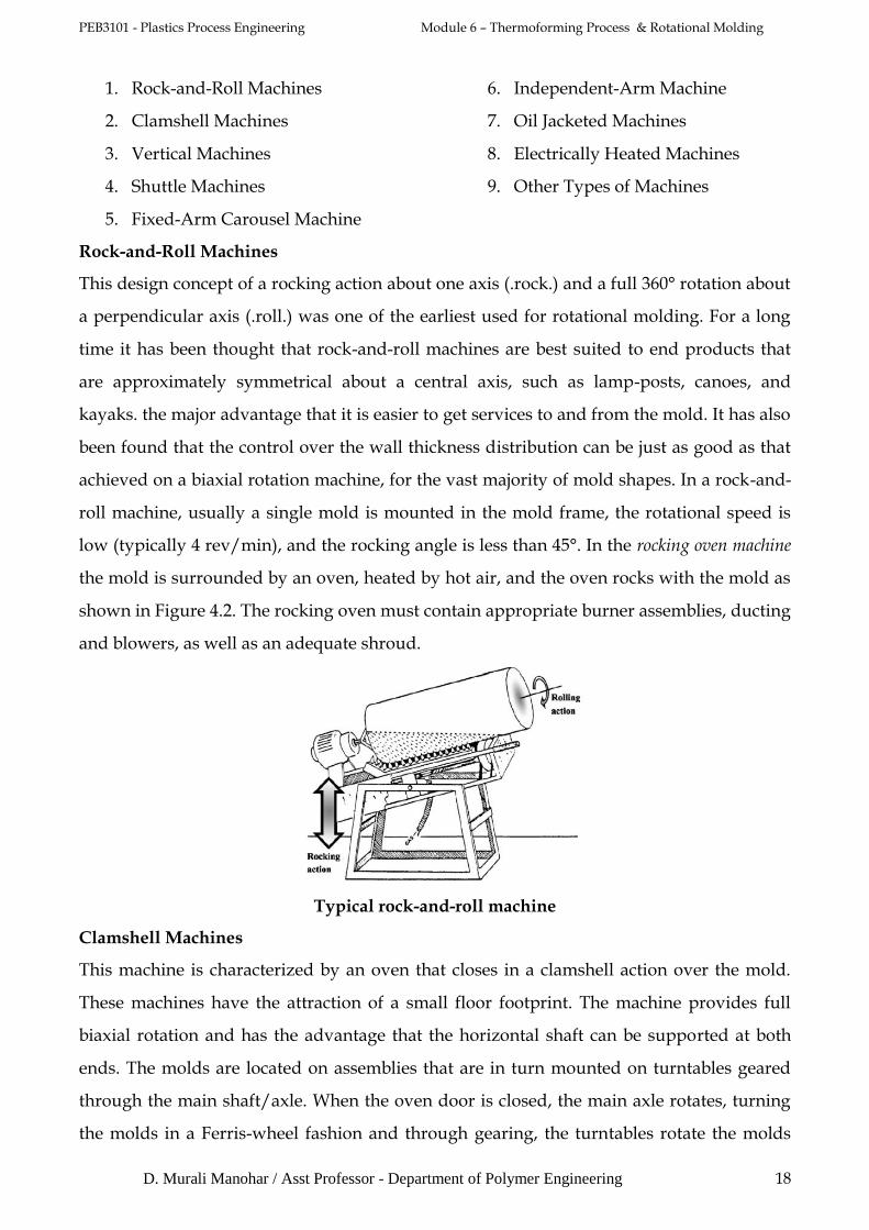
Rock-and-Roll Machines
This design concept of a rocking action about one axis (.rock.) and a full 360° rotation about
a perpendicular axis (.roll.) was one of the earliest used for rotational molding. For a long
time it has been thought that rock-and-roll machines are best suited to end products that
are approximately symmetrical about a central axis, such as lamp-posts, canoes, and
kayaks. the major advantage that it is easier to get services to and from the mold. It has also
been found that the control over the wall thickness distribution can be just as good as that
achieved on a biaxial rotation machine, for the vast majority of mold shapes. In a rock-and-
roll machine, usually a single mold is mounted in the mold frame, the rotational speed is
low (typically 4 rev/min), and the rocking angle is less than 45°. In the rocking oven machine
the mold is surrounded by an oven, heated by hot air, and the oven rocks with the mold as
shown in Figure 4.2. The rocking oven must contain appropriate burner assemblies, ducting
and blowers, as well as an adequate shroud.
Typical rock-and-roll machine
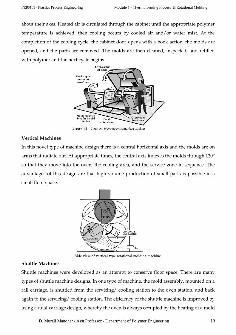
Clamshell Machines
This machine is characterized by an oven that closes in a clamshell action over the mold.
These machines have the attraction of a small floor footprint. The machine provides full
biaxial rotation and has the advantage that the horizontal shaft can be supported at both
ends. The molds are located on assemblies that are in turn mounted on turntables geared
through the main shaft/axle. When the oven door is closed, the main axle rotates, turning
the molds in a Ferris-wheel fashion and through gearing, the turntables rotate the molds
PEB3101 - Plastics Process Engineering Module 6 – Thermoforming Process & Rotational Molding
D. Murali Manohar / Asst Professor - Department of Polymer Engineering 19
about their axes. Heated air is circulated through the cabinet until the appropriate polymer
temperature is achieved, then cooling occurs by cooled air and/or water mist. At the
completion of the cooling cycle, the cabinet door opens with a book action, the molds are
opened, and the parts are removed. The molds are then cleaned, inspected, and refilled
with polymer and the next cycle begins.
Vertical Machines
In this novel type of machine design there is a central horizontal axis and the molds are on
arms that radiate out. At appropriate times, the central axis indexes the molds through 120°
so that they move into the oven, the cooling area, and the service zone in sequence. The
advantages of this design are that high volume production of small parts is possible in a
small floor space.
Shuttle Machines
Shuttle machines were developed as an attempt to conserve floor space. There are many
types of shuttle machine designs. In one type of machine, the mold assembly, mounted on a
rail carriage, is shuttled from the servicing/ cooling station to the oven station, and back
again to the servicing/ cooling station. The efficiency of the shuttle machine is improved by
using a dual-carriage design, whereby the oven is always occupied by the heating of a mold

PEB3101 - Plastics Process Engineering Module 6 – Thermoforming Process & Rotational Molding
D. Murali Manohar / Asst Professor - Department of Polymer Engineering 20
while the mold on the other carriage is being cooled/serviced. If the cooling/servicing time
for the mold equals the heating time, then this system can approach the optimum in terms
of maximum output rates.
Fixed-Arm Carousel Machine
The carousel, turret, or rotary machine was developed for long production runs of medium
to moderately large parts. It is now one of the most common types of machine in the
industry. The earliest machines had three arms 120° apart that were driven from a single
turret. All arms rotate together on fixed-arm machines. One arm is at each of the three
stations, heating, cooling, servicing at all times, The carousel machine exemplifies the
advantages of the rotational molding process in that different molds, and perhaps different
materials can be run on each arm. It is possible to change the combinations of molds on one
arm or on the other arms at regular intervals so that there is great versatility in production
schedules. A disadvantage of the fixed-arm machines is that for optimum use, heating,
cooling, and servicing times have to be matched. If they are not, then the cycle time is
dictated by the slowest event and time is wasted in the other areas. This disadvantage has
been overcome to some extent with the development of the independent arm carousel
machine.
Fixed-arm carousel machine
PEB3101 - Plastics Process Engineering Module 6 – Thermoforming Process & Rotational Molding
D. Murali Manohar / Asst Professor - Department of Polymer Engineering 21
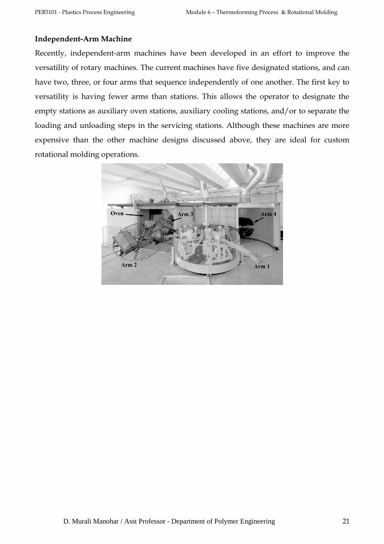
Independent-Arm Machine
Recently, independent-arm machines have been developed in an effort to improve the
versatility of rotary machines. The current machines have five designated stations, and can
have two, three, or four arms that sequence independently of one another. The first key to
versatility is having fewer arms than stations. This allows the operator to designate the
empty stations as auxiliary oven stations, auxiliary cooling stations, and/or to separate the
loading and unloading steps in the servicing stations. Although these machines are more
expensive than the other machine designs discussed above, they are ideal for custom
rotational molding operations.