Embed Size (px)
Citation preview

2
Module-I
Casting processes: Classification, Metal mould casting processes, advanced casting
processes, investment casting, Rheocasting, mould and core making materials and their
characteristics. Technology of Selected casting Processes: Clay bonded, synthetic resin
bonded, inorganic material bonded mould and core making, sand additives, mould coating,
continuous casting process, centrifugal casting process.
1. Introduction to Casting processes
Metal casting process begins by creating a mold, which is the ‘reverse’ shape of the part
we need. The mould is made from a refractory material, for example, sand. The metal is
heated in an oven until it melts, and the molten metal is poured into the mould cavity. The
liquid takes the shape of cavity, which is the shape of the part. It is cooled until it solidifies.
Finally, the solidified metal part is removed from the mould.
A large number of metal components in designs we use every day are made by casting.
The reasons for this include:
(a) Casting can produce very complex geometry parts with internal cavities and hollow
sections
(b) It can be used to make small (few hundred grams) to very large size parts (thousands of
kilograms)
(c) It is economical, with very little wastage: the extra metal in each casting is re-melted and
re-used
(d) Cast metal is isotropic – it has the same physical/mechanical properties along any
direction
Common examples: door handles, locks, the outer casing or housing for motors, pumps,
etc., wheels of many cars. Casting is also heavily used in the toy industry to make parts,
e.g. toy cars, planes, and so on. Typical metal cast parts are shown in Fig.1

3
Fig.1: Typical metal cast parts
Table 1 summarizes different types of castings, their advantages, disadvantages and
examples.
Table 1
4
1.1 Sand Casting: Sand casting uses natural or synthetic sand (lake sand) which is mostly
refractory material called silica (SiO2). The sand grains must be small enough so that it can
be packed densely; however, the grains must be large enough to allow gasses formed
during the metal pouring to escape through the pores. Larger sized molds use green sand
(mixture of sand, clay and some water). Sand can be re-used, and excess metal poured is
cut-off and re-used also.
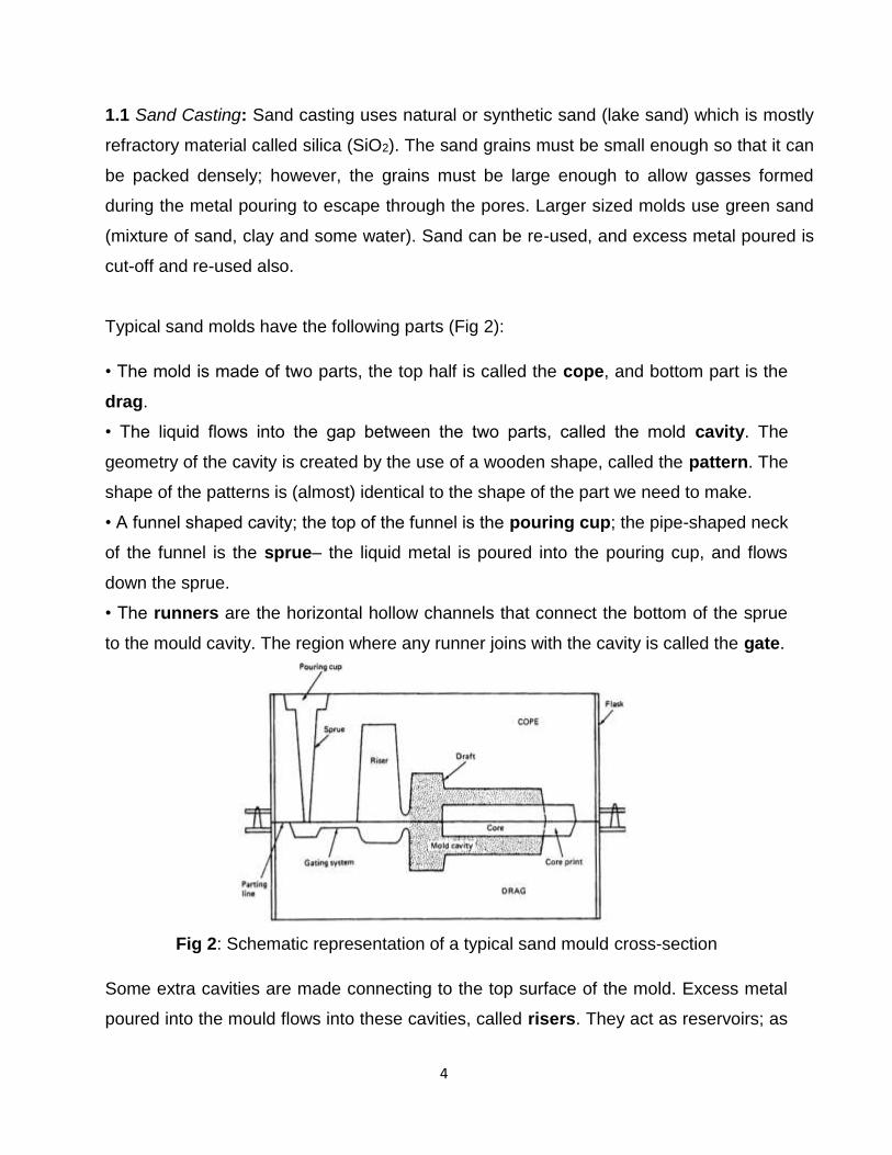
Typical sand molds have the following parts (Fig 2):
• The mold is made of two parts, the top half is called the cope, and bottom part is the
drag.
• The liquid flows into the gap between the two parts, called the mold cavity. The
geometry of the cavity is created by the use of a wooden shape, called the pattern. The
shape of the patterns is (almost) identical to the shape of the part we need to make.
• A funnel shaped cavity; the top of the funnel is the pouring cup; the pipe-shaped neck
of the funnel is the sprue– the liquid metal is poured into the pouring cup, and flows
down the sprue.
• The runners are the horizontal hollow channels that connect the bottom of the sprue
to the mould cavity. The region where any runner joins with the cavity is called the gate.
Fig 2: Schematic representation of a typical sand mould cross-section
Some extra cavities are made connecting to the top surface of the mold. Excess metal
poured into the mould flows into these cavities, called risers. They act as reservoirs; as
5
the metal solidifies inside the cavity, it shrinks, and the extra metal from the risers flows
back down to avoid holes in the cast part.
• Vents are narrow holes connecting the cavity to the atmosphere to allow gasses and the
air in the cavity to escape.
• Cores: Many cast parts have interior holes (hollow parts), or other cavities in their shape
that are not directly accessible from either piece of the mold. Such interior surfaces are
generated by inserts called cores. Cores are made by baking sand with some binder so
that they can retain their shape when handled. The mold is assembled by placing the
core into the cavity of the drag, and then placing the cope on top, and locking the mold.
After the casting is done, the sand is shaken off, and the core is pulled away and
usually broken off.
Gating System: Channel through which molten metal flows into cavity from outside of
mold consists of a downsprue, through which metal enters a runner leading to the main
cavity. At top of down-sprue, a pouring cup is often used to minimize splash and
turbulence as the metal flows into down-sprue.
1.2 Shell-mold Casting:
In this process the moulds and cores are prepared by mixing the dry free flowing sand
with thermosetting resins and then heating the aggregate (mixture of fine sand (100-150
mesh) and thermosetting resins) against a heated metal plate. Due to the heat, the resin
cures, which causes the sand grains to get bonded with each other and it forms a hard
shell around the metallic pattern. The inside portion of the shell is the exact replica of
the pattern against which the sand aggregate is placed before heating. The shape and
dimension of the inside portion of the shell thus formed is exactly the same as that of
the pattern. If the pattern is of two pieces then the other half of the shell is also prepared
the same way. Two halves of the shells prepared are placed together after inserting the
core, if any, to make the assembly of the mould. The assembly of the shell is then
placed in a molding flask and backing material is placed all around the shell mould
assembly to give its assembly the sufficient strength. Now the shell mould is fully ready
for pouring the liquid metal.

6
Sand
The dry free flowing sand used in the shell mould must be completely free of clay
content. The grain size of the sand used in shell molding is generally in the range of
100150 meshes, as the shell casting process is recommended for castings that require
good surface finish. However, depending on the requirement of surface finish of the final
casting, the grain size of the sand can be ascertained. Also, if the grain size is very fine,
it requires large amount of resins, making it expensive.
Resin and Catalyst
The resins most widely used, are the phenol formaldehyde resins, which are
thermosetting in nature. Combined with sand, they give very high strength and
resistance to heat. The resin initially has excess phenol and acts like a thermoplastic
material. In order to develop the thermosetting properties of the resin, the coating of the
sand is done with resin and a catalyst (Hexa-methylene-tetramine, known as Hexa).
The measure of resin is 4-6% of sand by weight, the catalysts 14-16% of sand by
weight. The curing temperature of the resin along with the catalysts is around 150o C
and the time required for complete curing is 50 – 65 seconds. The sand composition to
be used in making various casting of different materials can be seen from the relevant
standards.
The resins available are of water-bourn, flake, or the granular types. The specifications
of liquid, flakes or powder resins can be obtained from IS 8246-1976, IS 11266-1985,
and IS 10979-1981 respectively.
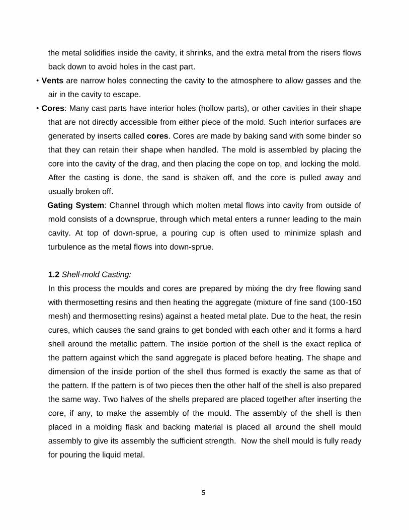
Shell-mold casting yields better surface quality and tolerances. The process is
described as follows:
- The 2-piece pattern is made of metal (e.g. aluminum or steel), it is heated to between
175°C-370°C, and coated with a lubricant, e.g. silicone spray.
- Each heated half-pattern is covered with a mixture of sand and a thermoset
resin/epoxy binder. The binder glues a layer of sand to the pattern, forming a shell. The
process may be repeated to get a thicker shell (Fig 3).
- The assembly is baked to cure it. 6
7
- The patterns are removed, and the two half-shells joined together to form the mold;
metal is poured into the mold.
- When the metal solidifies, the shell is broken to get the part.
Fig 3: Making the shell-mold and Shell mold casting
1.3 Expendable-pattern casting (lost foam process)
The pattern used in this process is made from polystyrene (this is the light, white packaging
material which is used to pack electronics inside the boxes). Polystyrene foam is 95% air
bubbles, and the material itself evaporates when the liquid metal is poured on it.
The pattern itself is made by molding – the polystyrene beads and pentane are put inside
an aluminum mold, and heated; it expands to fill the mold, and takes the shape of the
cavity. The pattern is removed, and used for the casting process, as follows:
- The pattern is dipped in slurry of water and clay (or other refractory grains); it is dried to
get a hard shell around the pattern.
- The shell-covered pattern is placed in a container with sand for support, and liquid metal
is poured from a hole on top.
- The foam evaporates as the metal fills the shell; upon cooling and solidification, the part is
removed by breaking the shell. 7
The process is useful since it is very cheap, and yields good surface finish and complex
geometry. There are no runners, risers, gating or parting lines – thus the design process is

8
simplified. The process is used to manufacture crank-shafts for engines, aluminum engine
blocks, manifolds etc.
Fig 4: Expendable mold casting
Details
The minimum wall thickness for a full-mold casting is 2.5 mm (0.10 in). Typical dimensional
tolerances are 0.3% and typical surface finishes are from 2.5 to 25 µm (100 to 1000 µin)
RMS. The size range is from 400 g (0.88 lb) to several tonnes (tons).
Full-mold casting is often used to produce cylinder heads, engine blocks, pump housings,
automotive brake components, and manifolds. Commonly employed materials include
aluminium, iron, steel, nickel alloys, and copper alloys.
Advantages and disadvantages
This casting process is advantageous for very complex castings that would regularly
require cores. It is also dimensionally accurate, requires no draft, and has no parting
lines so no flash is formed. As compared to investment casting, it is cheaper because it
is a simpler process and the foam is cheaper than the wax. Risers are not usually
required due to the nature of the process; because the molten metal vaporizes the foam
the first metal into the mold cools more quickly than the rest, which results in natural
directional solidification.

9
The two main disadvantages are that pattern costs can be high for low volume
applications and the patterns are easily damaged or distorted due to their low strength.
If a die is used to create the patterns there is a large initial cost.
1.4 Full Mold Process / Lost Foam Process / Evaporative Pattern Casting Process
The use of foam patterns for metal casting was patented by H.F. Shroyer on April 15,
1958. In Shroyer's patent, a pattern was machined from a block of expanded
polystyrene (EPS) and supported by bonded sand during pouring. This process is
known as the full mold process. With the full mold process, the pattern is usually
machined from an EPS block and is used to make primarily large, one-of-a kind
castings. The full mold process was originally known as the lost foam process.
However, current patents have required that the generic term for the process be full
mold.
In 1964, M.C. Flemmings used unbounded sand with the process. This is known today
as lost foam casting (LFC). With LFC, the foam pattern is molded from polystyrene
beads. LFC is differentiated from full mold by the use of unbounded sand (LFC) as
opposed to bonded sand (full mold process).
Foam casting techniques have been referred to by a variety of generic and proprietary
names. Among these are lost foam, evaporative pattern casting, and cavity less casting,
evaporative foam casting, and full mold casting.
In this method, the pattern, complete with gates and risers, is prepared from expanded
polystyrene. This pattern is embedded in a no bake type of sand. While the pattern is
inside the mold, molten metal is poured through the sprue. The heat of the metal is
sufficient to gasify the pattern and progressive displacement of pattern material by the
molten metal takes place.
The EPC process is an economical method for producing complex, close-tolerance
castings using an expandable polystyrene pattern and unbonded sand. Expandable
polystyrene is a thermoplastic material that can be molded into a variety of complex,

10
rigid shapes. The EPC process involves attaching expandable polystyrene patterns to
an expandable polystyrene gating system and applying a refractory coating to the entire
assembly. After the coating has dried, the foam pattern assembly is positioned on loose
dry sand in a vented flask. Additional sand is then added while the flask is vibrated until
the pattern assembly is completely embedded in sand. Molten metal is poured into the
sprue, vaporizing the foam polystyrene, perfectly reproducing the pattern.
1.5 Plaster-mold casting
The mold is made by mixing plaster of paris (CaSO4) with talc and silica flour; this is a fine
white powder, which, when mixed with water gets a clay-like consistency and can be
shaped around the pattern (it is the same material used to make casts for people if they
fracture a bone). The plaster cast can be finished to yield very good surface finish and
dimensional accuracy. However, it is relatively soft and not strong enough at temperature
above 1200°C, so this method is mainly used to make castings from non-ferrous metals,
e.g. zinc, copper, aluminum, and magnesium.
Since plaster has lower thermal conductivity, the casting cools slowly, and therefore has
more uniform grain structure (i.e. less warpage, less residual stresses).
1.6 Ceramic mold casting
Similar to plaster-mold casting, except that ceramic material is used (e.g. silica or
powdered Zircon ZrSiO4). Ceramics are refractory (e.g. the clay hotpot used in Chinese
restaurants to cook some dishes), and also have higher strength that plaster.
- The ceramic slurry forms a shell over the pattern;
- It is dried in a low temperature oven, and the pattern is removed 8
- Then it is backed by clay for strength, and baked in a high temperature oven to burn off
any volatile substances.
- The metal is cast same as in plaster casting.
This process can be used to make very good quality castings of steel or even stainless
steel; it is used for parts such as impellor blades (for turbines, pumps, or rotors for motor-
boats).

11
1.7 Investment casting (lost wax process)
The investment casting process, which is commonly referred to as the “lost wax method”,
originated in and around the fourth millennium B.C. It is evidenced through the architectural
works found in the form of idols, pectorals and jewelry in remains of the ancient Egypt and
Mesopotamia. The investment casting process initiates with the production of wax replicas
or patterns of the required shape of castings. Each and every casting requires a pattern to
be produced. Wax or polystyrene is made used as the injecting material. The assembly of
large number of patterns are made and attached to a wax sprue centrally. Metallic dies are
used to prepare the patterns. The pattern is immersed in refractory slurry which completely
surrounds it and gets set at room temperature forming the mold. The mold is further
heated, so that the pattern melts and flows out, leaving the required cavity behind. After
heating, the mold gets further hardened and molten metal is poured while it is still hot. After
the casting gets solidified, the mold is broken and it is taken out.
The basic steps of the investment casting process are as shown in Fig 5:
1. Preparing the heat-disposable wax, plastic or polystyrene patterns in a die. 2. Assembly
of the prepared patterns onto a gating system 3. “Investing,” (covering) the pattern
assembly with a refractory slurry which builds the shell.
4. Melting the pattern assembly (burning out the wax) by firing, for removing the traces of
the pattern material 5. The metal in molten state is poured into the formed mold. 6. Once
the metal solidifies, the shell is removed (knocked out). 7. Fettling (cutting off) of the
pouring basin and gates followed by finishing operations to get the desired dimensional
tolerances and finish.

12
Fig 5: The Basic Steps of the Investment Casting Process
Fig 5a: Steps in the investment casting process
This is an old process, and has been used since ancient times to make jewellery –
therefore it is of great importance to HK. It is also used to make other small (few grams,
though it can be used for parts up to a few kilograms). The steps of this process are shown
in the Fig 5a.

13
An advantage of this process is that the wax can carry very fine details – so the process not
only gives good dimensional tolerances, but also excellent surface finish; in fact, almost
any surface texture as well as logos etc. can be reproduced with very high level of detail.
1.8 Vacuum casting
This process is also called counter-gravity casting. It is basically the same process as
investment casting, except for the step of filling the mold. In this case, the material is
sucked upwards into the mould by a vacuum pump. The figure 6below shows the basic
idea – notice how the mold appears in an inverted position from the usual casting process,
and is lowered into the flask with the molten metal (Fig 6).
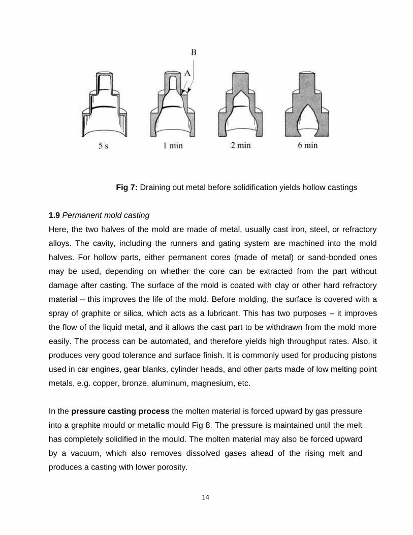
One advantage of vacuum casting is that by releasing the pressure a short time after the
mold is filled, we can release the un-solidified metal back into the flask. This allows us to
create hollow castings. Since most of the heat is conducted away from the surface between
the mold and the metal, therefore the portion of the metal closest to the mold surface
always solidifies first; the solid front travels inwards into the cavity. Thus, if the liquid is
drained a very short time after the filling, then we get a very thin walled hollow object, etc.
(Fig 7).
Fig 6: Vacuum casting
14
Fig 7: Draining out metal before solidification yields hollow castings
1.9 Permanent mold casting
Here, the two halves of the mold are made of metal, usually cast iron, steel, or refractory
alloys. The cavity, including the runners and gating system are machined into the mold
halves. For hollow parts, either permanent cores (made of metal) or sand-bonded ones
may be used, depending on whether the core can be extracted from the part without
damage after casting. The surface of the mold is coated with clay or other hard refractory
material – this improves the life of the mold. Before molding, the surface is covered with a
spray of graphite or silica, which acts as a lubricant. This has two purposes – it improves
the flow of the liquid metal, and it allows the cast part to be withdrawn from the mold more
easily. The process can be automated, and therefore yields high throughput rates. Also, it
produces very good tolerance and surface finish. It is commonly used for producing pistons
used in car engines, gear blanks, cylinder heads, and other parts made of low melting point
metals, e.g. copper, bronze, aluminum, magnesium, etc.
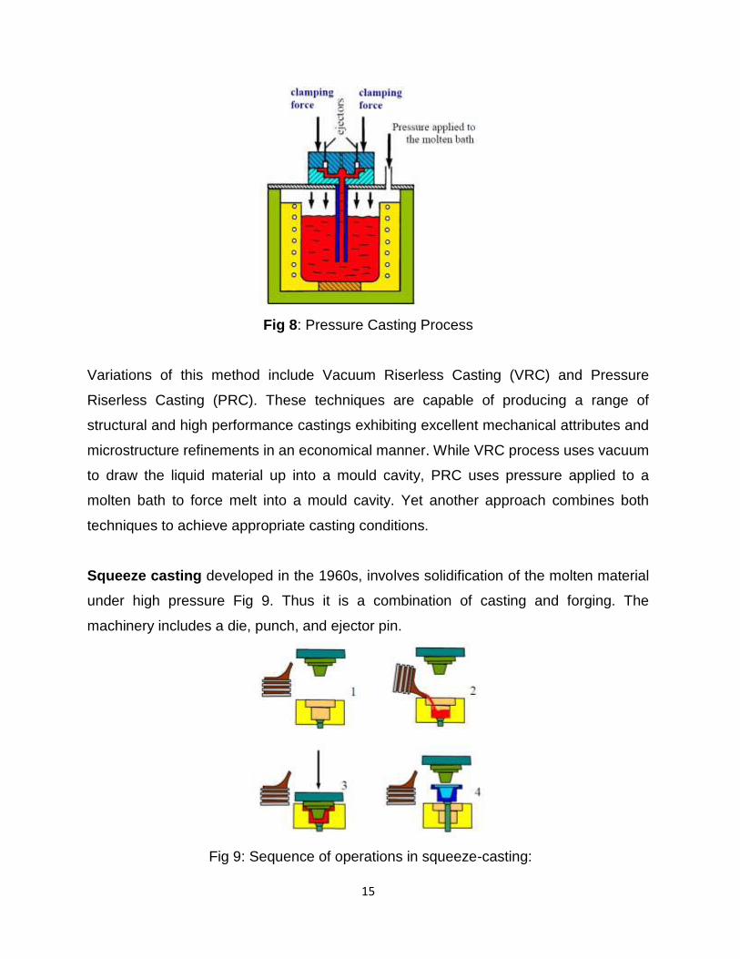
In the pressure casting process the molten material is forced upward by gas pressure
into a graphite mould or metallic mould Fig 8. The pressure is maintained until the melt
has completely solidified in the mould. The molten material may also be forced upward
by a vacuum, which also removes dissolved gases ahead of the rising melt and
produces a casting with lower porosity.
15
Fig 8: Pressure Casting Process
Variations of this method include Vacuum Riserless Casting (VRC) and Pressure
Riserless Casting (PRC). These techniques are capable of producing a range of
structural and high performance castings exhibiting excellent mechanical attributes and
microstructure refinements in an economical manner. While VRC process uses vacuum
to draw the liquid material up into a mould cavity, PRC uses pressure applied to a
molten bath to force melt into a mould cavity. Yet another approach combines both
techniques to achieve appropriate casting conditions.
Squeeze casting developed in the 1960s, involves solidification of the molten material
under high pressure Fig 9. Thus it is a combination of casting and forging. The
machinery includes a die, punch, and ejector pin.
Fig 9: Sequence of operations in squeeze-casting:

GATE Study Material Advanced castingand welding (Production And Industrial
Engineering)
Publisher : Faculty Notes Author : Panel Of Experts
Type the URL : http://www.kopykitab.com/product/10079
Get this eBook
84%OFF