Embed Size (px)
Citation preview
Airfield Geometric Design Prof. Amedeo Odoni
Air Transporta5on Systems and Infrastructure
Module 4
28 April 2014
Istanbul Technical University
Air Transporta5on Management
M.Sc. Program

Objective and Outline! Review briefly the rationale underlying
the geometric design specifications for airfields
Outline: - ICAO and FAA Reference Codes - Practical observations - Principal documents - Examples of specifications and
rationale Page 2
Page 3
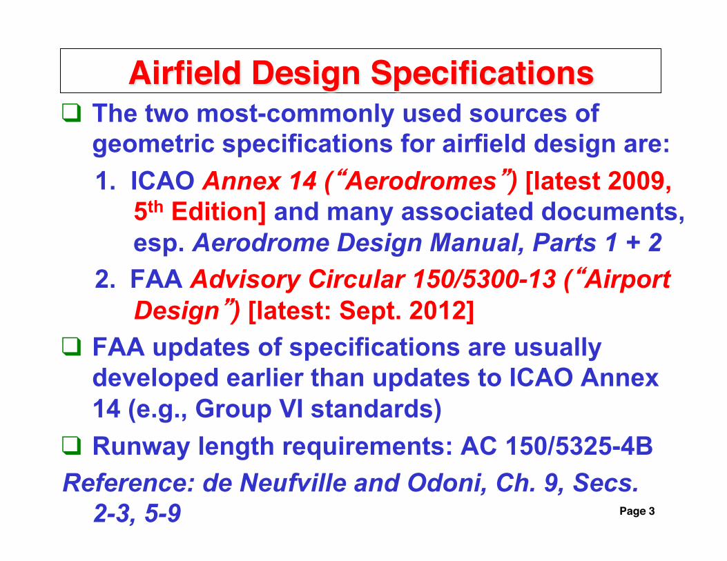
Airfield Design Specifications! The two most-commonly used sources of
geometric specifications for airfield design are: 1. ICAO Annex 14 (“Aerodromes”) [latest 2009,
5th Edition] and many associated documents, esp. Aerodrome Design Manual, Parts 1 + 2
2. FAA Advisory Circular 150/5300-13 (“Airport Design”) [latest: Sept. 2012]
FAA updates of specifications are usually developed earlier than updates to ICAO Annex 14 (e.g., Group VI standards)
Runway length requirements: AC 150/5325-4B Reference: de Neufville and Odoni, Ch. 9, Secs.
2-3, 5-9
Page 4
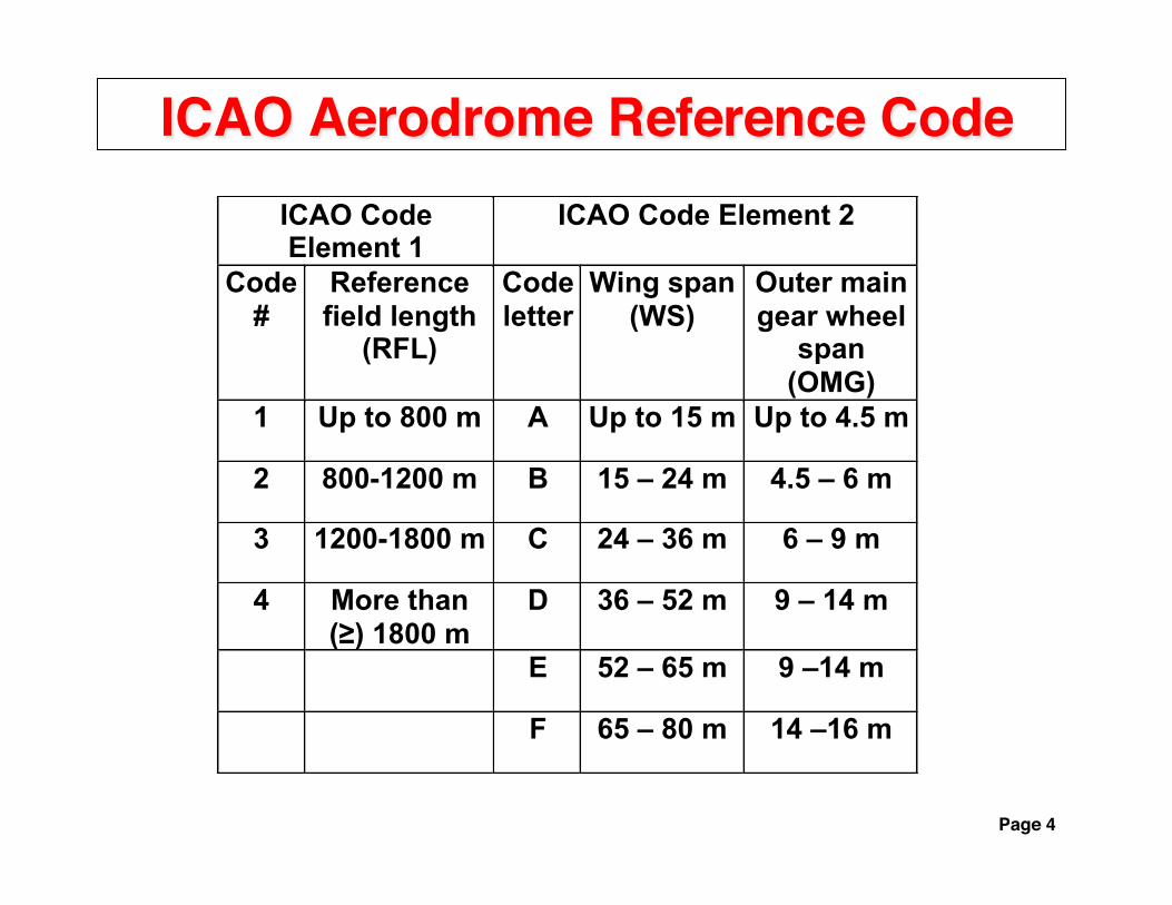
ICAO Aerodrome Reference Code!ICAO Code Element 1
ICAO Code Element 2
Code #
Reference field length
(RFL)
Code letter
Wing span (WS)
Outer main gear wheel
span (OMG)
1 Up to 800 m A Up to 15 m Up to 4.5 m
2 800-1200 m B 15 – 24 m 4.5 – 6 m
3 1200-1800 m C 24 – 36 m 6 – 9 m
4 More than (≥) 1800 m
D 36 – 52 m 9 – 14 m
E 52 – 65 m 9 –14 m
F 65 – 80 m 14 –16 m

Page 5
FAA Runway Design Code (RDC)!Aircraft Approach
Category (AAC) Approach Speed (AS)
A: < 91 knots
B: 91 – <121 knots
C: 121 – <141 knots
D: 141 – <166 knots
E: 166+ knots
Airplane Design Group (ADG) Wingspan (WS) Tail Height (TH) I: < 49 ft <20 ft
<15 m <6 m II: 49 – <79 ft 20 – <30 ft
15 – <24 m 6 – <9 m III: 79 – <118 ft 30 – <45 ft 24 – <36 m 9 – <13.5 m IV: 118 – <171 ft 45 – <60 ft
36 – <52 m 13.5 – <18.5 m V: 171 – <214 ft 60 – <66 ft 52 – <65 m 18.5 – <20 m VI: 214 – <262 ft 66 – <80 ft 65 – <80 m 20 – <24.5 m

Page 6
Remarks: ICAO and FAA Airport Reference Codes !
Practically all major commercial airports belong to the ICAO Code #4 class
In practice, Outer Main Gear Wheel Span (ICAO) is “dominated” by Wing Span
Similarly, Tail Height (FAA) is “dominated” by Wing Span
ICAO Code Letters A-F Wing Spans correspond exactly to FAA Airplane Design Groups I-VI wingspans
Most geometric specifications for airports are determined by the Wing Span of the most demanding aircraft
Page 7
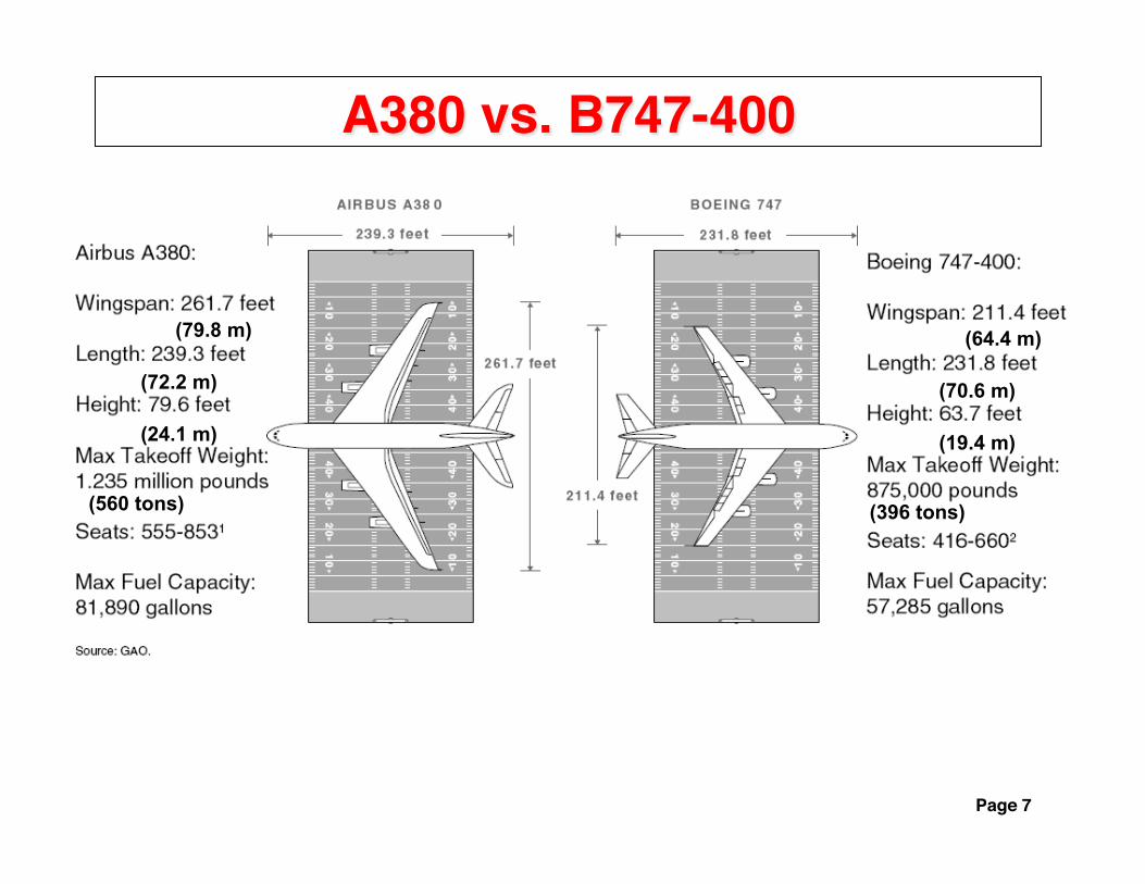
A380 vs. B747-400!
(72.2 m)
(79.8 m)
(24.1 m)
(64.4 m)
(70.6 m)
(19.4 m)
(560 tons) (396 tons)

Page 8
A380 vs. 777-300ER!
8
Note: Boeing 777-300ER Is longer than the A380

Page 9
●787-8
● ● A350-800 A350-900
● 747-8
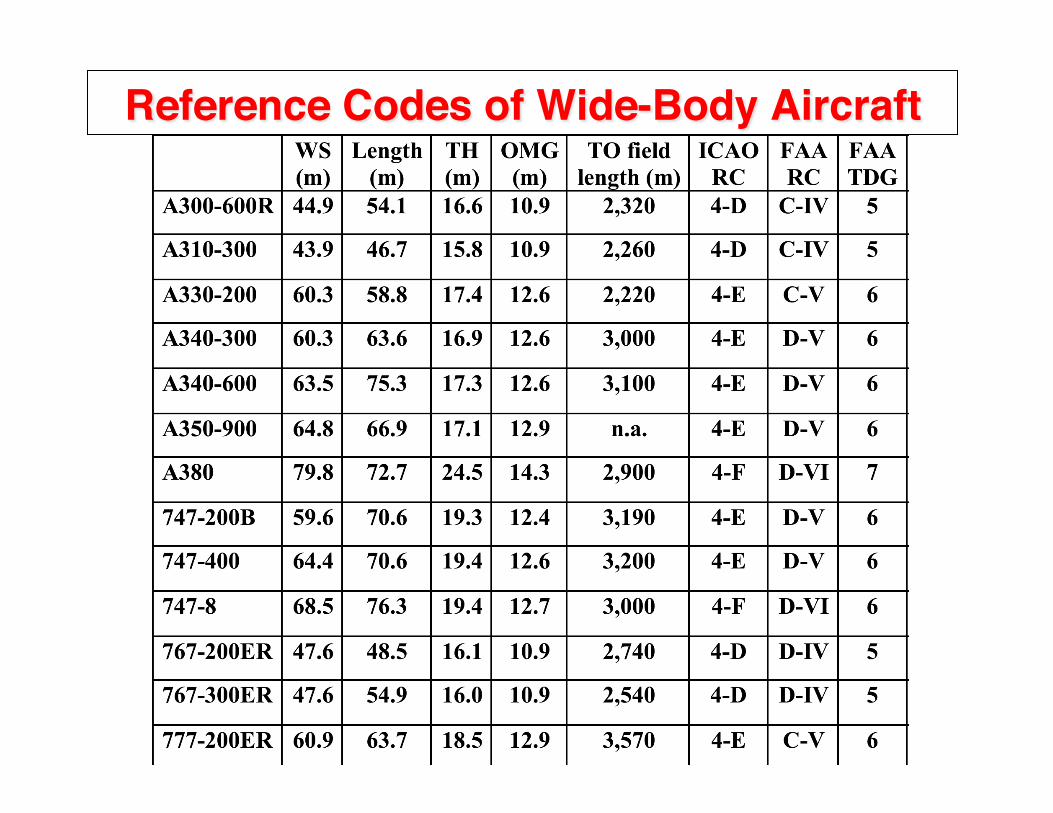
Reference Codes of Wide-Body Aircraft!
Page 10
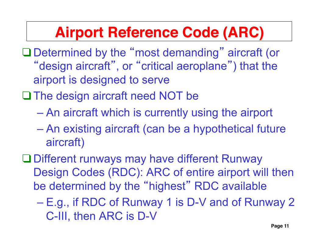
Airport Reference Code (ARC)! Determined by the “most demanding” aircraft (or “design aircraft”, or “critical aeroplane”) that the airport is designed to serve
The design aircraft need NOT be – An aircraft which is currently using the airport – An existing aircraft (can be a hypothetical future
aircraft) Different runways may have different Runway
Design Codes (RDC): ARC of entire airport will then be determined by the “highest” RDC available – E.g., if RDC of Runway 1 is D-V and of Runway 2
C-III, then ARC is D-V Page 11

Examples of Geometric Specifications (ICAO Annex 14)!
C D E F Runway width 45 45 45 60 Taxiway width 18 23 23 25 Runway centerline to taxiway centerline
168 176 182.5 190
Runway centerline to holdline 90 90 90 107.5 Taxiway centerline to taxiway centerline
44 66.5 80 97.5
Taxiway centerline to object 26 40.5 47.5 57.5 Taxilane centerline to object 24.5 36 42.5 50.5
Page 12
• Distances in meters; assumes instrument runway at sea level

Page 13
LAX Diagram (October 23, 2008)!

Page 14
LAX: Handling ADG VI Aircraft Today!

Rationale for Dimensional Specifications ! The rationale for many of the dimensional
specifications in the ICAO Annex 14 is provided in the Aerodrome Design Manual, Doc 9157 (Part 1: Runways, Part 2: Taxiways)
The Aerodrome Design Manual can also be used to estimate dimensional specifications for accommodating future aircraft development (e.g., Code Letter G)
The rationale for some of the FAA’s dimensional specifications can be found in Appendices 8 (Runways) and 9 (Taxiways) of older versions (e.g., 1989) of the FAA’s Airport Design advisory circular (AC 150/5300-13)
Page 15

ICAO: Taxiway Centerline to Taxiway Centerline!
Page 16
S = WS + C + Z For Code F, WS=80 m, C=4.5 m, Z=13 m; therefore S=97.5 m

Page 17
Single lane vs. dual lane access to stands!
Note as well:
• Taxiway to taxiway centerline: 1.2x(wingspan of most demanding a/c) + 10 ft (3m)
• Taxiway centerline to object: 0.7x(wingspan of most demanding a/c) + 10 ft (3m)
Source: FAA AC 150/5300-13 (1989 edition)

Page 18
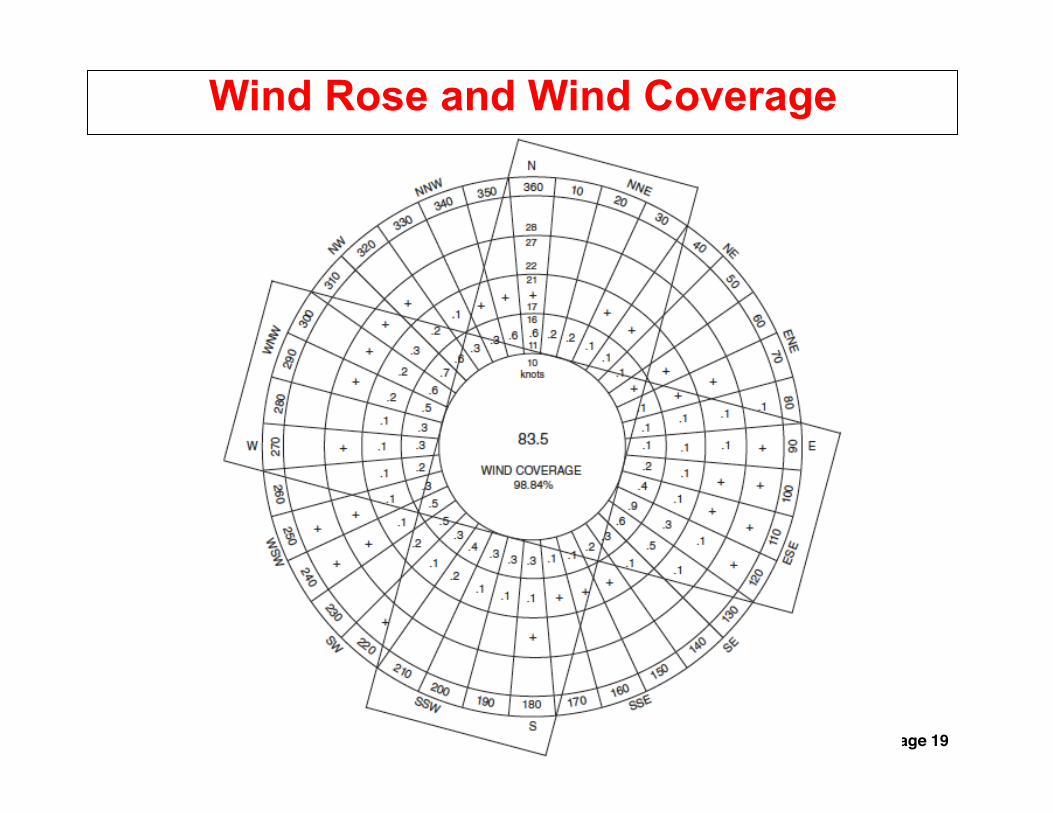
Wind Coverage (ICAO)! For operations on any given runway, crosswinds
should not exceed [FAA rules roughly the same]: – 37 km/h (20 knots) for aircraft whose reference
field length is 1500 m or more, except with poor braking action, when the limit is 24 km/h (13 knots)
– 24 km/h (13 knots) for reference field length between 1200 m and 1,499 m
– 19 km/h (10.5 knots) for reference field length of less than 1,200 m
Crosswind coverage (or “airport usability factor”) should be at least 95% [same with FAA]
Page 19
Wind Rose and Wind Coverage
Page 20
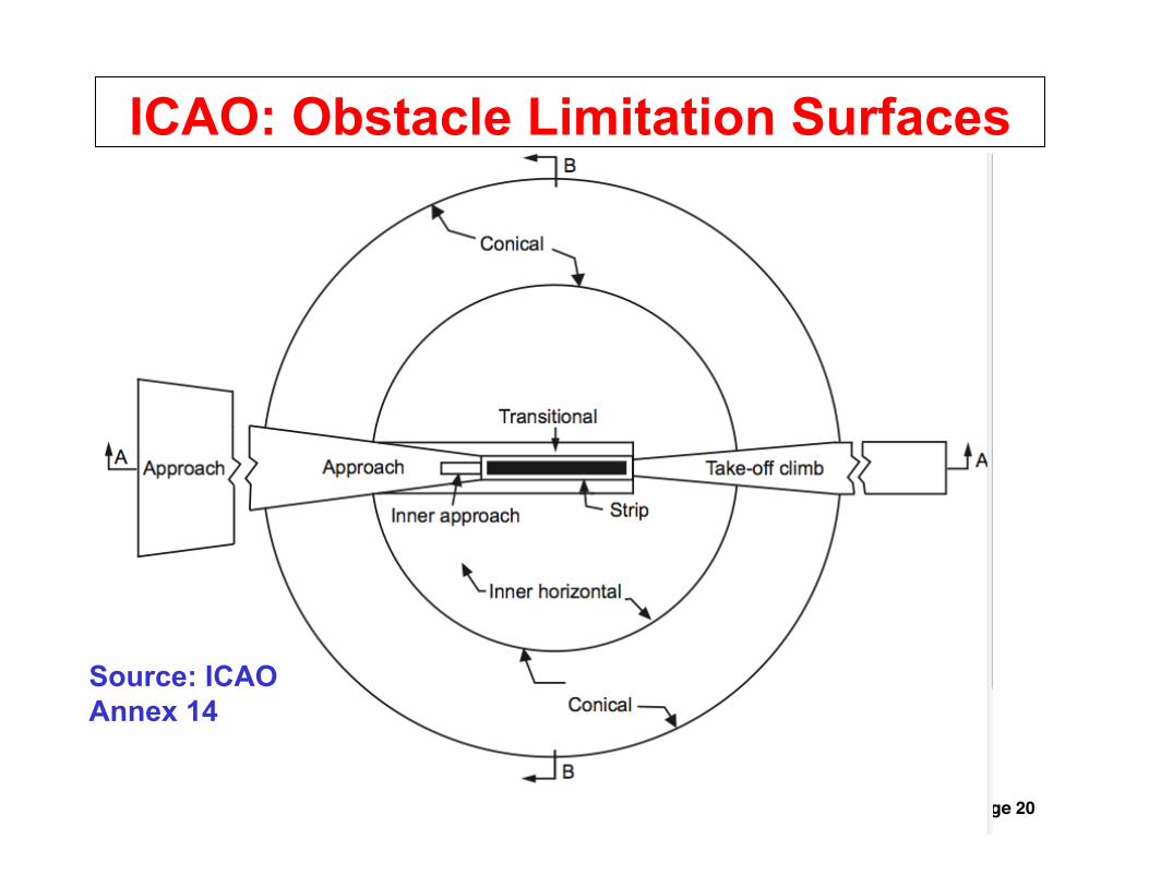
ICAO: Obstacle Limitation Surfaces
Source: ICAO Annex 14

Questions? Comments?!
Page 21