Embed Size (px)
DESCRIPTION
Module 1 - Preparing the Working Environment(NEW)
Citation preview
Module 1
1 Preparing the Working
Environment
2 Creating a Manikin and Workspace
3Using the
Human Measurements
Editor Performing
Human Activity Analysis
Performing Human Posture Analysis
Task Simulation Scenarios
45
6
Preparing the Working
Environment
Preparing the Working EnvironmentOverview
The first step in building a simulation is to set up a working environment that best reflects the needs and desired outcomes of the project. In this module, you will set the options necessary for this project.
After you have prepared the environment, you can begin to construct the 3D Workspace and add manikins.
Objectives
You will set options for Preparing the working environment You will learn how to use the 3d compass
2 hours
1
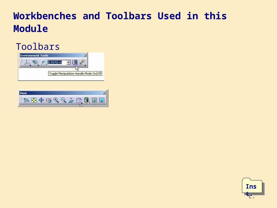
Workbenches and Toolbars Used in this Module
Toolbars
Inst.Inst.

Preparing the Working Environment1
Setting Options
A
2 hours
General DisplayParameters and MeasuresAEC PlantDigital Process for Manufacturing
3D Compass Settings
PPR TreeParameters for Compass ManipulationBasic TechniquesSnap Automatically to Selected ObjectEditing
Conventions Used in Online
Documentation
Depth EffectCATIAENOVIADELMIAGraphic Conventions
C
B

Setting Options
General DisplayParameters and MeasuresAEC PlantDigital Process for Manufacturing
A

Preparing the Working Environment
Setting Options
Setting Options
The Dassault Systemes family of software offers unprecedented power andflexibility to its users. Because of this, the software must be configured to fit your needs.
This process step is included to reinforce knowledge gained in the Introduction to V5 course and to configure the software to the particular needs of Human Solutions for this instruction.
1
Basic navigation, mouse control, and file management as well as complete detail of Tools/ Options can be found in the Introduction to V5 Course.
More about Tools / Options can be found in the online documentation
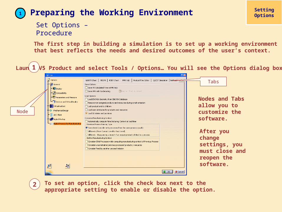
Launch V5 Product and select Tools / Options… You will see the Options dialog box. 1
2 To set an option, click the check box next to the appropriate setting to enable or disable the option.
The first step in building a simulation is to set up a working environment that best reflects the needs and desired outcomes of the user’s context.
Setting Options
Set Options – Procedure
Preparing the Working Environment 1
Node
Tabs
Nodes and Tabs allow you to customize the software.
After you change settings, you must close and reopen the software.

Setting Options – Exercise

Exercise – Set Options
Scope: You will set the software default options for the best performance for this project.
Conditions: V5 and DPM Assembly Process Simulation workbench must be open.
In this exercise you will:Set General options
Set Display options
Set Parameters and Measures options
Set AEC Plant options
Set DPM options
30 min.

Do It Yourself (1/1)
Node Tab Option Setting_____________________________________
General General Turn off Automatic backup every…Document Other Documents= requires Instructor direction
Display Tree Manipulation Turn on Automatic scrollVisualization Set Background to white (for this project)Navigation Turn on Display Manipulation Bounding box
Turn off Preselect in geometry viewTurn on Gravitational Effects and set to Z axis
Parameters & Measures Units Set Length to Inch (in)
Product Structure Cache Management Activate Work with the Cache System
Digital Process for Mfg Tree Activate Resource folders, Items folder, Attributes, Applicative Data, Output Product folder, and Logical Activities
AEC Plant General Set Grid step value to 0.5in
Set the following options
REMINDER: You must close and reopen the software for changes to take effect.
3D Compass Settings
PPR TreeParameters for Compass ManipulationBasic TechniquesSnap Automatically to Selected ObjectEditing
B

About 3D Compass Settings
1 Preparing the Working Environment3D Compass
Settings
The 3D Compass setting is a useful tool that you can manipulate in any direction. With the 3D Compass you can rotate or move the part or parts on the screen in any orientation.

1 Preparing the Working Environment3D Compass
Settings
2To change the size of the PPR tree click the line connecting the directories. On the View toolbar, select the Zoom In Out.
Click the line again to get back to 3D view. To display, or hide the PPR tree, select F3 on the keyboard.
To deactivate the zoom capability, go to the Tools / Options / General / Display / Tree Manipulation tab and uncheck Tree zoom after clicking on any branch option.
1
3D Compass Settings

3 To change the Depth Effect value, select View / Depth Effect. In the Near Limit field, activate the Fixed option and set the value to 100. In the Far Limit field, activate the Fixed option and set the value to 500000. Now you can zoom in on an item in the 3D view, and the clipping planes modify to only display the center of the field of visions center.
1 Preparing the Working Environment3D Compass
Settings
3D Compass Settings

1 Preparing the Working Environment
4 To find an object in the PPR tree, right click the object in 3D view and choose Center Graph from the menu.
On the main menu bar, select View / Toolbars to view the list.
Another way to view a toolbar is to drag them. To do this, left click and drag the move handle of the toolbar.
Some toolbars have imbedded toolbars. Use the black arrow to expand the toolbar, then select the move handle to drag it.
3D Compass Settings
5
6
3D Compass Settings
Preparing the Working Environment13D Compass
Settings
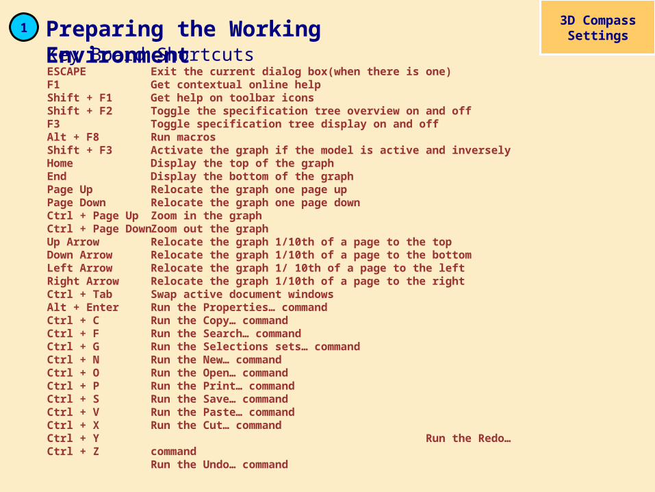
ESCAPEF1 Shift + F1Shift + F2F3Alt + F8 Shift + F3HomeEndPage UpPage DownCtrl + Page Up Ctrl + Page DownUp ArrowDown ArrowLeft ArrowRight ArrowCtrl + TabAlt + Enter Ctrl + CCtrl + FCtrl + GCtrl + NCtrl + OCtrl + PCtrl + SCtrl + VCtrl + XCtrl + YCtrl + Z
Exit the current dialog box(when there is one)Get contextual online helpGet help on toolbar iconsToggle the specification tree overview on and offToggle specification tree display on and offRun macrosActivate the graph if the model is active and inversely Display the top of the graphDisplay the bottom of the graphRelocate the graph one page upRelocate the graph one page downZoom in the graphZoom out the graph Relocate the graph 1/10th of a page to the topRelocate the graph 1/10th of a page to the bottomRelocate the graph 1/ 10th of a page to the leftRelocate the graph 1/10th of a page to the right Swap active document windowsRun the Properties… commandRun the Copy… commandRun the Search… commandRun the Selections sets… commandRun the New… commandRun the Open… commandRun the Print… commandRun the Save… commandRun the Paste… commandRun the Cut… command Run the Redo… commandRun the Undo… command
Key Board Shortcuts

1 Preparing the Working Environment 3D Compass Settings
Clicking an icon lets you run the command associated with that icon. Double-clicking an icon lets you use that command as many times as necessary.
Call outs are used throughout the project to give tips and expand explanations.
Click on line to adjust PPR tree
Minimize / Enlarge / Close / Window
PPR Tree
Expand /close
Some toolbars are hidden. Place the
mouse over the arrows and drag the toolbar
into the3D view.
Command promptor other information
ToolbarText window for
commandor function
Current
Workbench
3D VIEW WINDOW SIZE
BUTTON
3D Compass Settings

1 Preparing the Working Environment 3D Compass Settings
Sometimes when rotating or panning, the geometry disappears. To regain view, right-click the appropriate name on the PPR tree and select Reframe On. The object now reappears and the view zooms to it. Or you can use the Fit All In button.
Press and hold the middle mouse button to pan the model in the 3D view.
Press and hold the middle and the left mouse button to rotate the model in 3D view.
Press and hold the middle mouse button, press then release the left mouse button, then drag the mouse vertically to zoom the model in 3D view.
Click any line in the PPR tree, now use the mouse buttons as described to adjust the size and location of the PPR tree.
Basic Techniques

1 Preparing the Working Environment3D Compass
Settings
The 3D compass is used to manipulate viewpoint representations (“cameras”), which capture viewpoints.
The 3D compass is always active. Show and hide the compass by toggling the View / Compass command. Hiding the compass does not deactivate it.
The compass is displayed by default in the top right corner of the document. The letters, X,Y, and Z represent the axis. The Z-axis is the default orientation. The point close to the Z-axis is the free rotation handle used for freely rotating the compass and the document’s objects at the same time.
The red square is the compass manipulation handle that you can use to drag the compass and place on objects to manipulate. You can also rotate objects around this point. The base of the compass, the XY plane, is the privileged plane. This concept is not useful when using the select command: it is only useful when using application commands that use manipulators, or which require working planes.
Free rotation handle
Privileged plane
Compass manipulation handle
3D Compass Settings

1 Preparing the Working Environment 3D Compass Settings
Right-click the 3D Compass to display its contextual menu. From this menu, select Snap Automatically to Selected Object. In the 3D view, or in the PPR tree, select any object. The compass will immediately snap to that object.
To reset the compass to the default position, select View / Reset Compass from the main menu.
To move the compass, place the mouse pointer over the red box, and click the left mouse button. The pointer changes to a grasping hand. Drag the mouse and compass toward an object in the 3D view and the compass will snap to that object.
In the contextual menu, select Edit. The parameter for Compass Manipulation appears. The current coordinates of the compass manipulation handle (red square), with respect to the center of the world, are displayed in the axis fields.
7
9
CoordinatesSet the Coordinate values to move and rotate objects.
IncrementsSet the Incremental values for translation and rotation.
8
10
3D Compass Settings

Conventions Used in Online
Documentation
Depth EffectCATIAENOVIADELMIAGraphic Conventions
C

About Conventions used in Online Documentation
1 Preparing the Working EnvironmentConventions
used in Online Documentation
Graphic conventions indicating the required configuration are denoted as follows:
This icon... Indicates functions that are...
specific to the P1 configuration
specific to the P2 configuration
specific to the P3 configuration

1 Preparing the Working EnvironmentConventions
used in Online Documentation
The use of the mouse differs according to the type of action you need to perform.
Select (menus, commands, geometry in the graphics area, …)Click (icons, dialog box buttons, tabs, selection of a location in the document window, …)Double-clickShift-clickCtrl-clickCheck (check boxes)DragDrag and drop (icons onto objects, objects onto objects)
DragMove
Right-click (to select contextual menu)
Conventions used in Online Documentation

1 Preparing the Working EnvironmentConventions
used in Online Documentation
This icon... Identifies...
estimated time to accomplish a task
a target of a task
the prerequisites
the start of the scenario
a tip
a warning
information
basic concepts
methodology
reference information
information regarding settings, customization, etc.
the end of a task
functionalities that are new or enhanced with this release
allows you to switch back to thefull-window viewing mode

1 Preparing the Working EnvironmentConventions
used in Online Documentation
When DELMIA software is launched it opens the last workbench used in the previous session by default.
In this example, the default is the fasteners process planning workbench
Conventions used in Online Documentation

Preparing the Working Environment – Summary
Module Summary
This module has introduced you to setting options necessary to building the simulation project. In addition, you have also learned about the 3D compass and how to use it in your simulation.
Coming Up You will learn how to create a workspace and insert manikins into the simulation workplace.
1