Embed Size (px)
Citation preview

Module 3: Preparing for Cluster Service
Installation

Overview
Pre-Installation Requirements
Identifying Hardware Considerations
Assigning IP Addresses Within a Cluster
Assigning Names Within a Cluster
Determining Domain Considerations
Existing Services and Applications

This module covers the information that is required to plan for the installation of Microsoft® Cluster service. Requirements specific to server clusters include communication networks, shared disks, and data storage, in addition to hardware considerations for the operating system. This module describes the naming and addressing conventions that the cluster components require. Domain considerations are covered, in addition to issues relating to services and applications that were installed and running prior to installing Cluster service.

After completing this module, you will be able to:
Determine the pre-installation requirements for a server cluster.
Identify hardware considerations.
Assign Internet Protocol (IP) addresses within a cluster.
Assign names within a cluster.
Determine domain considerations.
Determine pre-installation considerations for existing services and applications.

Pre-Installation Requirements
ClientClient
ClientClient
ClientClient
ClientClient
RouterRouter
ServerServer
PowerPower

Before installing Cluster service you will need to plan for failures that could occur in the environment. You also need to consider how the nodes in the cluster will communicate with each other, and how clients will access the server cluster. Additionally, you must ensure that your system will have the shared disks and data storage that are required for a successful Cluster service installation.

Backup and Restore
Clustering technology provides increased reliability; however, it is not designed to protect all of the components of your workflow in all circumstances. For example, Cluster service is not an alternative to backing up data, because it protects only the availability of data, not the data itself. Therefore, you need to plan for backup and restoration of data.

Risk Assessment
It is recommended that prior to creating a cluster, you complete a risk assessment of your network to identify possible single point of failures that can interrupt access to network resources. A single point of failure is any component in the environment that would block client access to data or applications if it failed. Single points of failure can be hardware, software, or external dependencies. Examples of single points of failure include dedicated wide area network (WAN) lines or the power supply from a utility company.

Uninterruptible Power Supply
Another recommendation is to consider providing an uninterruptible power supply (UPS) protection for individual computers and the network, including hubs, bridges, and routers. A UPS is just one more factor in configuring a total fault tolerant solution. Many UPS solutions provide power for 5 to 20 minutes, which is long enough for the Microsoft Windows® 2000 operating system to properly shut down when power fails.

Cluster Network Requirements
Public Network
Private Network
Mixed Network
PrivateNetwork
Public or Mixed
Network

A cluster network has two primary types of communication. The private communication provides online status and other cluster information to the nodes. The public communication provides information between the client and virtual servers. It is recommended that private network communications be physically separated from public network communications, but have the ability to use the mixed network to eliminate a single point of failure.

An alternative network type a mixed network, uses the public network for both private and public communications. The advantage of a mixed network is that private network communications can be failed over to the public network. If you dedicate a network to client-to-node communications, node-to-node communications cannot fail over to that network. The mixed network configuration is the preferred configuration for a public network.
Network adapters, known to the cluster as network interfaces, attach nodes to networks. You configure what types of communication will travel across the networks by using the cluster administration tools.

Private Network
The private network, also known as the interconnect in a server cluster, will potentially carry the following five types of information:
Server heartbeats
Replicated state information
Cluster commands
Application commands
Application data

Server heartbeats. Each node in a cluster exchanges IP packets (approximately every 1.2 seconds) with the other node in the cluster determining if both nodes are running correctly. The first node of the cluster to come online is the node that is responsible for sending out the heartbeats. The second node begins to send heartbeats to inform the first node that the second node has come online. If a node does not respond to the heartbeat, the working node identifies the unresponsive node as having failed. If a node fails to detect six successive heartbeats from another node, the other node assumes that the unresponsive node is offline and tries to take ownership of the resources that the nonresponding node owns. Note that failure to detect a heartbeat message can be caused by node failure, network interface failure, or network failure.

Replicated state information. Every node in the cluster uses replicated state information to communicate which cluster groups and resources are running on all of the other nodes.

Cluster commands. Cluster commands manage and change the cluster configuration. An example of a cluster command would be any node-tonode communications regarding adding or removing a resource or failing over a group.

Application commands. Cluster-aware applications send application commands through the interconnect to communicate with copies of an application running on multiple servers.
Application data. Application data is when cluster-aware applications share data between nodes.
Note: If the private network fails over to the public network, the Cluster service employs packet signing for node-to-node communications to provide additionalsecurity over the network.

Public Network
The public network connection extends beyond the cluster nodes and is used for client-to-cluster communication. The public network cannot function as a backup connection for node-to-node communication should the private network fail. The network interface cards (NICs) for the public network must be on the same subnet.

Mixed Network
The typical server cluster will have one NIC on each server that is designated for internal communications (cluster only), and one or more other NICs designated for all communications (the mixed network serving both cluster and client). In such a case, the cluster-only NIC is the primary interconnect, and the mixed network NIC(s) serves as a backup if the primary ever fails.
Cluster service can only do this for the primary cluster interconnect. That is, it provides the ability to use an alternate network for the cluster interconnect if the primary network fails. This eliminates an interconnect NIC from being a single point of failure. There are vendors who offer fault tolerant NICs for Windows 2000 Advanced Server, and you can use these for the NICs that connect the servers to the client network.

Cluster Disk Requirements
All Disks on Shared Bus
Disks Can Be Seen from All Nodes
Basic Disks, not Dynamic
All Disk Partitions must be NTFS
Hardware RAID not Software RAID

A shared disk is a resource that all of the nodes in a cluster can access. This shared disk will be known as the cluster disk after installation of Cluster service. The cluster disk allows clients to access data even if a node goes offline.

To install Cluster service on Windows 2000 with a properly functioning cluster disk, you will need to make certain that:
All of the shared disks, including the quorum disk, are physically attached to a shared bus or buses.
Disks attached to the shared bus can be seen from all of the nodes. You can verify that you can see all of the nodes at the host adapter setup level.
Shared disks are configured as basic, not dynamic.
All disks must be formatted NTFS.
Cluster service supports hardware RAID not software RAID.
Note: While not required, the use of fault tolerant hardware Redundant Arrayof Independent Disks (RAID) is strongly recommended for all cluster disks.

Data Storage Requirements
C:
D:
C:
Y:
X:
Local Disk 0Local Disk 0
Node BNode B
Cluster Disk 21 PartitionCluster Disk 21 Partition
Cluster Disk 12 PartitionsCluster Disk 12 Partitions
Node A Disk Configuration:C: = Local Disk 0W: = Cluster Disk 1X: = Cluster Disk 1Y: = Cluster Disk 2
Node B DiskConfiguration:C: = Local Disk 0D: = Local Disk 1W: = Cluster Disk 1X: = Cluster Disk 1Y: = Cluster Disk 2
W:
Node ANode A
Local Disk 0Local Disk 0
Local Disk 1Local Disk 1

Cluster service is based on the shared nothing model of clustering. In a shared nothing model, only one node in the cluster can logically control a disk resource at a time. Having only one node controlling a disk resource at any given time allows the Windows 2000 cluster file system to support the native NTFS file system rather than requiring a dedicated cluster-aware file system.

Identical Drive Letters
After you have configured the bus, disks, and partitions, you must assign drive letters to each partition on each clustered disk. Drive letters for cluster disks and partitions must be identical on both nodes. For example, Microsoft SQL Server™ is running on a virtual server that Node A controls with the SQL database on drive W. If the virtual server fails over to Node B, SQL server can access data on Node B’s drive W.
Note: It is usually best to assign drive letters from the end of the alphabet to avoid duplicate drive letters.

Identifying Hardware Considerations
Selecting a Cluster Service Compatible System
Routers, Switches, and Hubs
Network Cards
Cluster Disk
Cluster Data Access

You can choose from a wide range of cluster compatible systems that meet the minimum Cluster service requirements. It is recommended that all of the hardware be identical for both nodes. Using identical hardware makes configuration easier and eliminates potential compatibility problems. Microsoft supports only complete cluster configurations that have passed cluster validation testing. Select the Cluster category in the Hardware Compatibility List (HCL) at http://www.microsoft.com/hcl/default.asp to view the list of tested and validated configurations.

The HCL also lists various system components, such as small computer system interface (SCSI) adapters, Fibre Channel adapters, and RAID devices, that have passed cluster component candidate testing.
Warning: Using hardware that is incompatible with Cluster service can result in a variety of problems, including failure of the nodes to start or to restart. It is strongly recommended that you use hardware that is on the Windows 2000 Hardware Compatibility List for Cluster service.

Cluster Service Compatible Systems
Dual PCI Bus
PCI Disk Controller
Separate Disk Controller for the shared bus
PCI Network Adapter
External Hard Disk
Cables and Terminators

Each node in a cluster requires all of the hardware requirements for Windows 2000 Advanced Server, plus the following requirements that are specific to Cluster service:

A Dual Peripheral Component Interconnect (PCI) bus

A PCI disk controller

A separate disk controller from the operating system that must be used for the shared data bus

A minimum of one PCI network adapter
Note: ISA network cards are not suitable for use in a cluster because of slow throughput. Saturation on an ISA card can lead to delays in packet transmission for up to ten seconds. Cluster service will wait for five seconds before determining failover of the other node.

An external hard disk that is connected to both computers that the cluster will use as the shared disk

Cables and terminators to attach the disk to both computers and properly terminate the bus
Note: The Cluster Verification utility from www.microsoft.com will verify proper installation of a two-node cluster. However, the tests that are performed on the cluster will destroy all data on the clustered disks. Do not use this utility with an established cluster.

Routers, Switches, and Hubs
\\AccountingIP 10.0.0.5
RouterIP 192.168.5.1MAC 00-D8-60-33-FA
NodeAIP 10.0.0.1MAC 00-40-96-32-37-BA
NodeBIP 10.0.0.2MAC 00-D0-59-12-0F-00
\\Accounting=IP 10.0.0.5MAC 00-40-96-32-37-BA
\\Accounting=IP 10.0.0.5MAC 00-D8-60-33-FA
\\Accounting=IP 10.0.0.5MAC 00-40-96-32-37-BA
\\AccountingIP 10.0.0.5
ARPUpdate

A server cluster installation requires hardware compatible routers, switches, and hubs. For the client to respond to a failed virtual server, Microsoft Cluster service sends a gratuitous Address Resolution Protocol (ARP) update to the network devices. The ARP update notifies the client of the new media access control (MAC) to IP address association. The clients can then redirect client to virtual server communication to the new controlling node.

You need to verify that hubs and switches can forward the ARP update to clients and routers. However, some devices, such as switches, may not forward the gratuitous ARP request to other devices. Hubs will always forward ARP updates. A switch may not forward the update, but you can configure it to forward the updates. A router never forwards the update,\; however it needs to be able to accept the update and change its ARP table. It is important to choose and test routers and switches for compatibility prior to implementation of a server cluster.

In this example, Node A is controlling \\Accounting with an IP address of 10.0.0.5. The clients and routers contain an address table of the IP to MAC relationships. When the virtual server changes ownership, Node B sends out a gratuitous ARP update to the local subnet. Hubs and switches forward the information to clients and routers on the local subnet. Routers contain an IP to MAC address table on behalf of clients on remote subnets, therefore routers do not forward the information but must be able to accept the ARP update.
Network Cards
Network Descriptions
Supported Network Types
10 BaseT
100 BaseT
FDDI Network Card
Specialized Interconnects

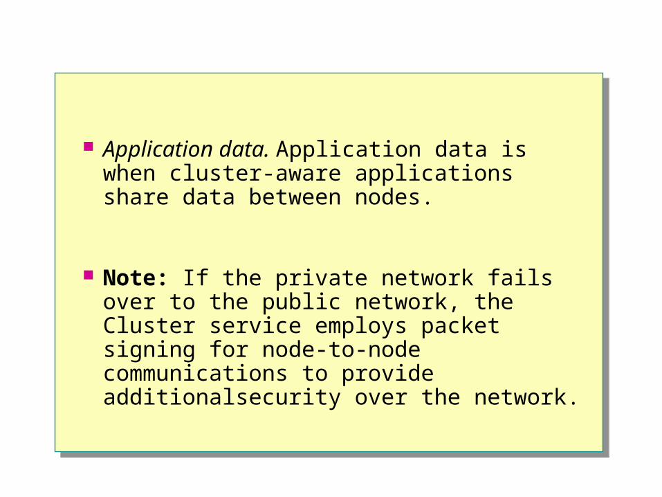
The typical server cluster has one NIC on each server which is designated for internal, cluster-only communications. One or more other NICs are designated for all public communications, including a mixed network that can serve both cluster and client.

Network Descriptions
If the cluster node uses multiple, identical PCI network cards, it may be difficult to identify them when you run the Cluster service setup. Microsoft Windows 2000 setup assigns network descriptions to each card. You will need to identify which network cards that the cluster will use for private, public, or mixed cluster networks, and enter descriptions for each.
Network Descriptions (ii)
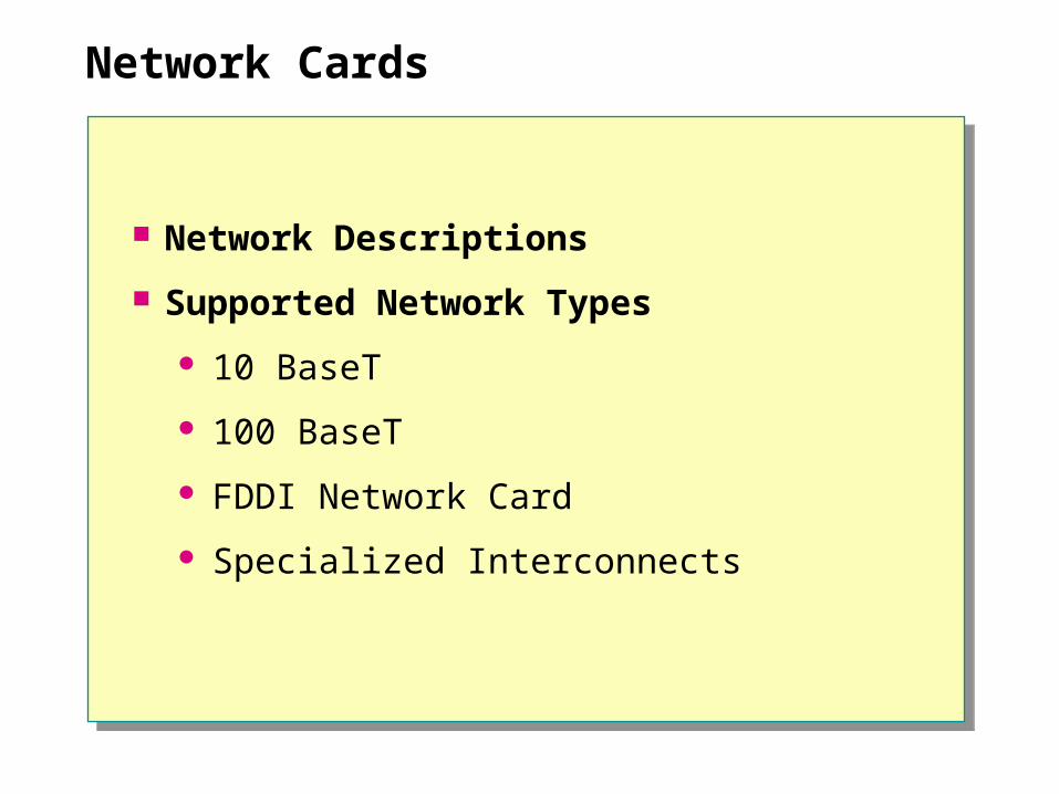
For example, you would use the Transmission Control Protocol/Internet Protocol (TCP/IP) Ipconfig utility to display the network driver name with an index (such as E190x1 and E190x2) and the network card’s IP address and subnet mask. Using this information, you can then assign appropriate names to the networks when you run the Cluster service setup. For example, if El90x1 uses a private IP address 10.0.0.1, this address is for node-to-node communication. If El90x2 uses an IP address on the public network, this address is for client-to-node communication.
Note: Two network adapters are recommended so that the nodes of the cluster can have a private network for node-to-node communications.

Supported Network Types
A supported Cluster service configuration can use as its interconnect virtually any network technology that Windows 2000 Advanced Server supports. This includes the following:
10BaseT Ethernet
100BaseT Ethernet
Fiber Distributed Data Interface (FDDI) network card
Specialized interconnect technologies such as Tandem ServerNet and
GigaNet Cluster LAN (cLAN)

Cluster Disk
Hardware RAID
Disk Access Speed
Multiple Shared Bus
Hardware RAIDSingle Disk

Applications and services access data that is stored on the cluster disk. In a multiple server environment, throughput may become a concern on the shared bus. You need to consider the demand for data from the applications and services on the cluster to decide whether to implement the following cluster disk solutions.

Hardware RAID
You could configure hardware RAID on the external disk device. Hardware RAID will increase data access on the cluster disk for greater performance. A stripe set, a feature of RAID, will also provide faster read/write functionality for data access.

Disk Access
Another alternative is to select a faster disk, realizing that you will then need a wider bus. A faster disk will provide increased read/write functions for data access. For example, you may select a wide SCSI with a maximum transfer rate of 20 megabytes (MB) per second, or you may select an ultra-wide SCSI with a maximum transfer rate of 40 MB per second.

Multiple Shared Bus
If you have a number of disks on the same, shared bus, you may find a decrease in performance of read/write data access. In an active/active cluster environment, both nodes access disks on the same shared bus. To increase read/write performance, consider moving some disks to a separate shared bus.
Note: Cluster service does not support the use of software RAID for the cluster disks.

Cluster Data Access
SCSI Requirements for Cluster Service
Fibre Requirements for Cluster Service

Cluster service accesses data that is shared by either a SCSI bus or a Fibre Channel bus. Based on the amount of throughput that is needed for your cluster, you will need to decide which will meet your requirements.
SCSISCSI Fibre ChannelFibre Channel
Cost Lower cost Increased cost
Configuration Difficult Easy
Storage Area Network (SAN) –capable
Not supported Supported
Hardware Requirements No specialized equipment Specialized equipment
Transfer Rate Performance 160 MB per second 266 MB per second
Optical Cables N/A 10 km (maximum)
Copper Cables 25 meters 100 meter

SCSI Requirements for Cluster Service
A PCI SCSI card must have the following features for cluster communications:
The ability to turn off autobus reset.
The ability to configure a unique SCSI Controller ID.
A unique ID for all of the devices on the SCSI bus.
Note: A shared SCSI bus has two controllers, and each controller must have a different SCSI ID. The default SCSI ID is 7 or 15. You will need to change one SCSI ID to a unique number on the shared bus.
Termination at both ends of the bus.

Note: The SCSI card and the last disk in the SCSI chain usually handle termination within a computer. On an external shared SCSI bus, a resistor provides termination. As a best practice, you can use a SCSI Y cable to provide access to a terminator, the SCSI card, and the shared disks. Using a SCSI Y cable allows you to disconnect the card from the bus in case you need to take the computer offline or have it serviced.

Fibre Channel Requirements for Cluster Service
A Fibre Channel card must have the following features for cluster communications:
A PCI Fibre Channel card or Host Bus Adapter (HBA)
Fibre switch or Fibre hub
Storage compatible disk arrays
Fibre Channel RAID array

Assigning IP Addresses Within a Cluster
PrivateNetwork
PublicNetwork
Public Net Cluster10.0.2.7
255.255.255.0
Public Net Cluster10.0.2.7
255.255.255.0
Public NetNode A10.0.2.4
255.255.255.0
Public NetNode B10.0.2.5
255.255.255.0
Private NetNode A10.0.1.5
255.255.255.0
Private NetNode B10.0.1.6
255.255.255.0

Cluster service uses TCP/IP to communicate with either public or private networks and requires statically assigned IP addresses.
Cluster service requires a minimum of three addresses from the public address space to configure a cluster. You assign an IP address to the public NIC on each node for clients to communicate directly to that node, independent of the cluster. You assign the third address to the cluster as a virtual server, primarily for client access. The private NIC in each cluster node is also assigned an IP address. Because you use this interface as a private subnet between cluster nodes, you do not need to assign private addresses from the public address pool.

You may require additional addresses depending on the nature of the applications that are being served. Each virtual server on the cluster will have its own unique IP address.
An important feature of using IP addresses for virtual servers is the ability to fail over an IP address between nodes. The virtual server IP address remains the same after fail over. It is released from the original node and bound to the public network card on the new node.

Static IP Addresses
Cluster service does not support the use of IP addresses that are assigned from a Dynamic Host Configuration Protocol (DHCP) server for the cluster service, or for any IP address resources. However, you can use either static IP addresses or IP addresses that are permanently leased from a DHCP server. Because a DHCP server can cause the failure of even a permanently reserved address, using static IP addresses is recommended to ensure the highest degree of availability.

If you are configuring the cluster’s private network, consider assigning addresses from one of the private networks that the Internet Assigned Numbers Authority (IANA) defines: 10.0.0.0–10.255.255.255 (Class A),
Subnet Mask: 255.0.0.0
172.16.0.0–172.31.255.255 (Class B), Subnet Mask: 255.255.0.0
192.168.0.0–192.168.255.255 (Class C), Subnet Mask 255.255.255.0
Important: It is recommended that you use a static TCP/IP address on the cluster private network. Cluster service can use the automatic private ddressing feature of Windows 2000 but this feature can slow down the startup time of a server.

Assigning Names Within a Cluster
\\NodeA\\NodeA
\\NodeB\\NodeB
\\Cluster\\Cluster \\Accounting\\Accounting
A Client can use\\NodeA to
Manage NodeA
A Client can use\\Accounting to
access the Virtual Server
A Client can use\\Cluster to Manage the
Cluster

When installing Cluster service, there are three types of names that you will assign to each part of the server cluster. All of the names must conform to standard network basic input/output system (NetBIOS) naming conventions. You will need to assign a Cluster service NetBIOS name to each of the following components:

Node Name. Each node of the cluster needs a server name or node name for management of the server. Each node is listed in WINS, Dynamic DNS and Active Directory™ Users and Computers.

Cluster Name. The cluster name refers to the first virtual server created during the installation of Cluster service. The network administrator uses the cluster name to configure and administer the cluster. If the network administrator has configured each node to use WINS and Dynamic DNS, the cluster name will also be registered on the network. Cluster names are not listed in Active Directory Users and Computers.

Virtual Server Name. Each virtual server needs a name that clients use to gain access to resources on virtual servers. If the network administrator has configured the node to use WINS and DDNS, each virtual server name will also be listed. Virtual server names are not listed in Active Directory Users and Computers.
Note: In a Windows Internet Naming Service environment, Node Names, Cluster Names and Virtual Server Names register their name with the WINS server for NetBIOS name resolution.

The NetBIOS namespace within a network must be different from all of the other namespaces and is 16 characters in length. Microsoft networking components, such as Windows 2000 and Windows 2000 Server services, allow the user or administrator to specify the first 15 characters of a NetBIOS name, but reserve the 16th character of the NetBIOS name to indicate a resource type (00-FF hex). You can register names as unique (one owner) or as group (multiple owners) names.

Determining Domain Considerations
User Accounts
Computer Accounts

Prior to the installation of Cluster service, you must assign each server a computer account on the Windows 2000 domain. Cluster service uses domain authentication to interact with the user accounts on the same domain.

There are two types of accounts:
User accounts. You use the administrator account for installation, and the service account for administration and maintenance of the server cluster.
Computer account. The computer account identifies the computer as a member of the domain for administrative purposes.

You can install Cluster service on Windows 2000 or Microsoft Windows NT® version 4.0 domains, but you cannot install it to a workgroup environment because the service account cannot run on a local node. A domain controller must validate the service account.

User Accounts
Administrator Account on Each Node
Cluster Service Account

There are two required accounts for the installation and maintenance of Cluster service: a user account with administrator rights and a service account.

Administrator account. To install Cluster service, you will need to be logged on as a user with administrator’s rights on each node of the cluster. The Cluster Installation Wizard verifies that the user has the appropriate permissions to install Cluster service.

Service account. When you install Cluster service, you specify the domain user account under which Cluster service runs. You use the service account to start and maintain Cluster service. You can locate the service account on both nodes of a member server’s account database or on the Active Directory. It is recommended that you locate this account in Active Directory.

The Service account must have the following user account settings:
Log on as a service right.
Administrator privileges.
Password never expires.
User cannot change password.

Computer Accounts
DomainDomain
OrganizationalUnits
OrganizationalUnits

You install server cluster nodes as either Windows 2000 domain controllers or as member servers. It is recommended that you install Cluster service on member servers to draw away the server workload from domain controller activity.
You integrate cluster nodes in Active Directory as computer objects. The server cluster name and all of the defined virtual servers in the cluster are not represented as computer objects. However, you can publish resources, such as file shares, in Active Directory.
Note: It is recommended that you create a separate organizational unit for all of the cluster nodes, to keep them separated from any group policies that might affect servers in Active Directory.

Node Domain Roles
Both nodes should have the same domain role, either both member servers in the same domain or both domain controllers in the same domain. Cluster nodes should not hold Flexible Single Master Operations roles, such as the Primary Domain Controller (PDC) emulator.

Existing Services and Applications
Pre-ClusterPre-Cluster Cluster InstalledCluster Installed
Server A running:WINSDNSDHCP
Server B running:Exchange
Node A running:WINSDNSDHCP
Node B:Exchange Fails
Virtual Serverrunning:
DHCP

Existing applications and services running on a server prior to the formation of a cluster are not normally impacted by the installation of Cluster service. However, before installing Cluster service, you need to test the applications and services to ensure that they will continue to provide full functionality when the servers are installed in the cluster.
Some applications and services continue to run on the server post-installation, but will not take advantage of the functionality of Cluster service until they are migrated into the cluster. You cannot migrate other applications into a server cluster and must uninstall them prior to installing Cluster service.

For example, in this slide, prior to installing Cluster service, Server A is running WINS, DNS, and DHCP. You can migrate all three as a resource into the server cluster after you install Cluster service on Node A. Node B is running Microsoft Exchange, which you cannot migrate into a cluster. If you install Cluster service on the resource is in the process of being brought online. Node B, Exchange will fail.
Prior to installing Cluster service on a server, you need to check with the software licensing requirements of the vendors whose applications and services are running on that server.

Lab A: Configuring Advanced Server for Cluster Installation

Objectives
After completing this lab, you will be able to:
Set up a shared disk for cluster installation.
Set up public and private networks for cluster installation.

Prerequisites
Before working on this lab, you must be familiar with the concepts in Course 2087A, Module 3, “Preparing for Cluster Service Installation.”

Scenario
You will start the lab with nothing installed except Windows 2000 Advanced Server, which is installed as a member server in the NWTRADERS domain. You will work individually to prepare your computer to participate in the cluster. You will set up a common drive letter on the disk that is shared by the two computers in the cluster and configure the public and private networks.
Your lab computers have been assigned a NetBIOS name. The following exercises will refer to your computers as NodeA and NodeB.

Exercise 1: Set up Shared Disk for Cluster Installation
In this exercise, you will configure a common drive letter that Cluster service will use during the installation. Applications store data on drive letters not disks. For a cluster-aware application that is installed on both nodes to access data that is stored on the shared disk, both nodes in the cluster must use the same drive letter.

To set up a shared disk for cluster installation
Complete this task from both the NodeA and NodeB computers.
1. Log on to your domain as Administrator with a password of password.
2. Click Start, point to Programs, point to Administrative Tools, and then click Computer Management.
3. In Computer Management, click Disk Management.
4. Verify that the Type for Disk 1 is Basic.
5. Right-click Disk 1, and then click Change Drive Letter and Path.
6. In the Change Drive Letter and Paths for Disk 1 dialog box, click Edit.
7. In the Edit Drive Letter or Path dialog box, click the Assign a drive letter drop-down box and select drive W:, and then click OK.
8. In the Confirm dialog box, click Yes.
9. Close Computer Management.

Exercise 2: Set up Public and Private Networks for Cluster Installation
In this exercise you will determine which network card that you will use for the public and private network cluster networks. The classroom is configured to use a static IP number for the public network and automatic addressing for the private network. You will configure the TCP/IP address.

To set up public and private networks for cluster installation
Complete this task from both the NodeA and NodeB computers.
1. Click Start, point to Settings, and then click Control Panel.
2. Double-click Network and Dial-up Connections.
3. Right-click Local Area Connection, and then click Properties.
4. Write down the network card from the Connect using: box.
5. From the Local Area Connection Properties dialog box, double-click Internet Protocol [TCP/IP].
6. Write down the IP address from the Use the following IP address: dialog box. If Obtain an IP address automatically is selected, write down DHCP.

7. Click OK from the Internet Protocol (TCP/IP) Properties dialog box.
8. Click OK from the Local Area Connection Properties dialog box.
9. Right-click Local Area Connection, and then select Rename.
10. Local Area Connection is selected. If you wrote DHCP in step 6, rename Local Area Connection to Cluster Private. If you wrote a static TCP/IP number in step 6, rename the connection to Cluster Public.
11. Right-click Local Area Connection 2, and then click Properties.
12. Write down the name of the network card from the Connect using: box.

13. From the Local Area Connection 2 Properties dialog box, double-click Internet Protocol [TCP/IP].
14. Write down the IP address from the Use the following IP address: dialog box. If Obtain an IP address automatically is selected, write down DHCP.
15. Click OK from the Internet Protocol (TCP/IP) Properties dialog box.
16. Click OK from the Local Area Connection 2 Properties dialog box.
17. Right-click Local Area Connection 2, and then select Rename.
18. Local Area Connection 2 is selected. If you wrote DHCP in step 14, rename Local Area Connection 2 to Cluster Private. If you wrote a static TCP/IP number in step 14, rename the connection to Cluster Public.
19. Close all of the windows.

Exercise 3: Using the Pre-Installation Checklist
In this exercise, you will work with your partner to fill out the Pre-Installation Checklist. This checklist is intended to help you plan your Cluster service installation. Use the following Reference Table to fill in the names and IP addresses.

Review
Pre-Installation Requirements
Identifying Hardware Considerations
Assigning IP Addresses Within a Cluster
Assigning Names Within a Cluster
Determining Domain Considerations
Existing Services and Applications