Embed Size (px)
DESCRIPTION
Module 1 Fundamentals of Crystal structure. Internal STRUCTURE for external strength. Materials. Non Crystalline. Crystalline. The properties of some materials are directly related to their crystal structures - PowerPoint PPT Presentation
Citation preview

Name of Institution
1
Module 1
Fundamentals of Crystal structure
Internal STRUCTURE for external strength

Name of Institution
2
The properties of some materials are directly related to their crystal structures
Solid materials may be classified according to the regularity with which atoms or ions are arranged with respect to one another
A crystalline material is one in which the atoms are situated in a repeating or periodic array over large atomic distances
Materials
Crystalline Non Crystalline

Name of Institution
3
CRYSTAL STRUCTURES
upon solidification, the atoms will position themselves in a repetitive three-dimensional pattern, in which each atom is bonded to its nearest-neighbor atoms
All metals, many ceramic materials, and certain polymers form crystalline structures under normal solidification conditions

Name of Institution
4
Some of the properties of crystalline solids depend on the crystal structure of the material, the manner in which atoms, ions, or molecules are spatially arranged
When describing crystalline structures, atoms (or ions) are thought of as being solid spheres having well-defined diameters. This is termed the atomic hard sphere model in which spheres representing nearest-neighbor atoms touch one another
Sometimes the term lattice is used in the context of crystal structures; in this sense ‘‘lattice’’ means a three-dimensional array of points coinciding with atom positions
Name of Institution
5
UNIT CELLS
The atomic order in crystalline solids indicates that small groups of atoms form arepetitive pattern
Thus, in describing crystal structures, it is often convenient to subdivide the structure into small repeat entities called unit cells
Unit cells for most crystal structures are parallelepipeds or prisms having three sets of parallel faces
A unit cell is chosen to represent the symmetry of the crystal structure
wherein all the atom positions in the crystal may be generated by translations of the unit cell integral distances along each of its edges
unit cell is the basic structural unit or building block of the crystal structure and defines the crystal structure by virtue of its geometry and the atom positions within

Name of Institution
6
Metallic crystal structures
Three relatively simple crystal structures are found for most of the common metals:
Face-centered cubic
Body-centered cubic
Hexagonal close-packed.

Name of Institution
7
THE FACE-CENTERED CUBIC CRYSTAL STRUCTURE
The crystal structure found for many metals has a unit cell of cubic geometry, with atoms located at each of the corners and the centers of all the cube faces. It is aptly called the face-centered cubic (FCC) crystal structure
Example: copper, aluminum, silver, and gold
(a) hard sphere unit cell b) reduced-sphere unit cellc)aggregate ofmany atoms

Name of Institution
8
These spheres or ion cores touch one another across a face diagonal; the cube edge length a and the atomic radius R are related through
Each corner atom is shared among eight unit cells
Whereas a face-centered atom belongs to only two
Therefore, one eighth of each of the eight corner atoms and one half of each of the six face atoms, or a total of four whole atoms, may be assigned to a given unit cell

Name of Institution
9
Coordination number
For metals, each atom has the same number of nearest-neighbor or touching atoms, which is the coordination number.
For F C C, the coordination number is 12•the front face atom has four corner nearest-neighbor atoms surrounding it• four face atoms that are in contact from behind• four other equivalent face atoms residing in the next unit cell to the front
Atomic packing factor (APF)
APF is the fraction of solid sphere volume in a unit cell, assuming the atomic hard sphere model
For the FCC structure, the atomic packing factor is 0.74, which is the maximumpacking possible for spheres all having the same diameter

Name of Institution
10
THE BODY-CENTERED CUBIC CRYSTAL STRUCTURE
Another common metallic crystal structure also has a cubic unit cell with atoms located at all eight corners and a single atom at the cube center. This is called a body-centered cubic (BCC) crystal structure
(a) hard sphere unit cell b) reduced-sphere unit cell c)aggregate of many atoms

Name of Institution
11
Center and corner atoms touch one another along cube diagonals, and unit cell length a and atomic radius R are related through
Two atoms are associated with each BCC unit cell
The coordination number for the BCC crystal structure is 8
Also is the atomic packing factor for BCC is 0.68

Name of Institution
12
THE HEXAGONAL CLOSE-PACKED CRYSTAL STRUCTURE
The top and bottom faces of the unit cell consist of six atoms that form regular hexagons and surround a single atom in the center
Another plane that provides three additional atoms to the unit cell is situated between the top and bottom planes
The atoms in this mid plane have as nearest neighbors atoms in both of the adjacent two planes
The equivalent of six atoms is contained in each unit cell
If a and c represent, respectively, the short and long unit cell dimensions the c/a ratio should be 1.633
The coordination number and the atomic packing factor for the HCP crystalstructure are the same as for FCC: 12 and 0.74, respectively

Name of Institution
13
Name of Institution
14
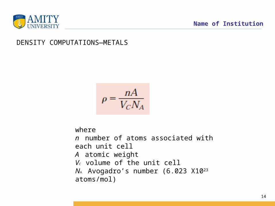
DENSITY COMPUTATIONS—METALS
wheren number of atoms associated with each unit cellA atomic weightVC volume of the unit cellNA Avogadro’s number (6.023 X10²³
atoms/mol)
Name of Institution
15
crystal systems (Unit cell geometry)
• It is sometimes convenient to divide them into groups according to unit cell configurations and/or atomic arrangements
• One such scheme is based on the unit cell geometry
• that is, the shape of the appropriate unit cell parallelepiped without regard to the atomic positions in the cell

Name of Institution
16
• An x, y, z coordinate system is established
• Origin at one of the unit cell corners
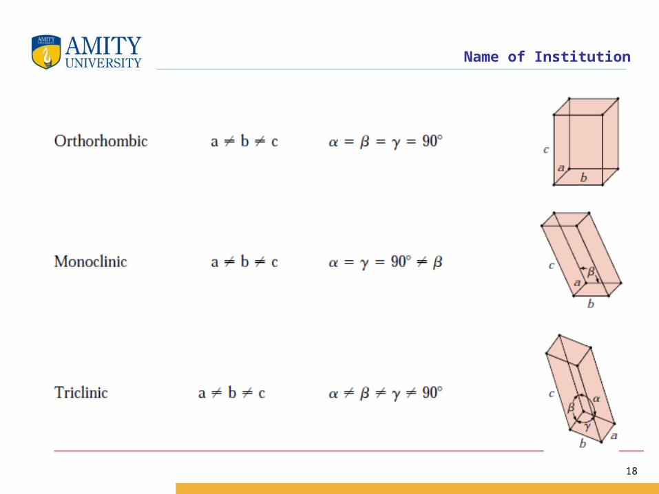
The unit cell geometry is completely defined in terms of six parameters
The three edge lengths a, b, and c, and the three interaxial angles α,β and γ
The cubic system, for which a= b= c and α=β=γ=90 has the greatest degree of symmetry
Least symmetry is displayed by the triclinic system a ≠ b≠c, and α≠β≠γ

Name of Institution
17
Unit Cell Geometries for the Seven Crystal Systems
Name of Institution
18
Name of Institution
19
Crystallographic Points, Directions and Planes
When dealing with crystalline materials, it often becomes necessary to specify someParticular point within a unit cell, a crystallographic direction or some crystal lographic plane of atoms
Three numbers or indices are used to designate point locations, directions and planes
The basis for determining index values is unit cell
Consisting of three ( x, y and z) axes situated at one of the corners and coinciding with unit cell edges
For some crystal systems—namely, hexagonal, rhombohedral, monoclinic, and triclinic— the three axes are not mutually perpendicular, as in the familiar Cartesiancoordinate scheme

Name of Institution
20
Point Coordinates:
The position of any point located within a unit cell may be specified in terms of its coordinates as fractional multiples of the unit cell edge lengths (i.e in terms of a, b and c) .
Name of Institution
21
CRYSTALLOGRAPHIC DIRECTIONS
A crystallographic direction is defined as a line between two points, or a vector.The following steps are utilized in the determination of the three directionalindices
1. A vector of convenient length is positioned such that it passes through the origin of the coordinate system.
2. The length of the vector projection on each of the three axes is determined; these are measured in terms of the unit cell dimensions a, b, and c
3. These three numbers are multiplied or divided by a common factor to reduce them to the smallest integer values
4. The three indices, not separated by commas, are enclosed in square brackets, thus: [uvw]. The u, v, and w integers correspond to the reduced projections along the x, y, and z axes, respectively
Name of Institution
22
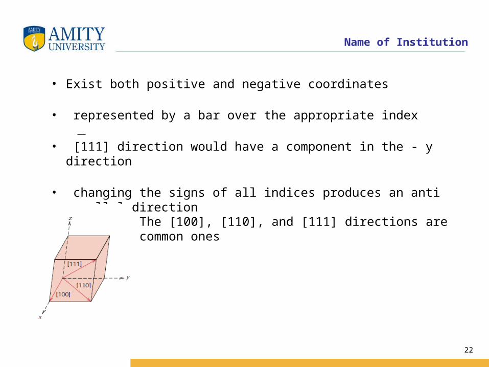
• Exist both positive and negative coordinates
• represented by a bar over the appropriate index
• [111] direction would have a component in the - y direction
• changing the signs of all indices produces an anti parallel direction
The [100], [110], and [111] directions are common ones

Name of Institution
23
For some crystal structures, several nonparallel directions with different indices are actually equivalent This means that the spacing of atoms along each direction is the same
For example, in cubic crystals, all the directions represented by the following indices are equivalent: [100], [100], [010], [010], [001], and [001].
As a convenience, equivalent directions are grouped together into a family, which are enclosed in angle brackets, thus <100>.
Furthermore, directions in cubic crystals having the same indices without regard to order or sign, for example, [123] and [213], are equivalent

Name of Institution
24
HEXAGONAL CRYSTALS
A problem arises for crystals having hexagonal symmetry in that some crystallographic equivalent directions will not have the same set of indices
This is circumvented by utilizing a four-axis, or Miller–Bravais, coordinate system
The three a1 , a2 , and a3 axes are all contained within a single plane (called the basal plane), and at 120 angles to one another
• The z axis is perpendicular to this basal plane
• Directional indices, which are obtained as described above, will be denoted by four indices, as [uvtw]
• By convention, the first three indices pertain to projections along the respective a1 , a2 , and a3 axes in the basal plane

Name of Institution
25

Name of Institution
26
Conversion from the three-index system to the four-index system
Is accomplished by the following formulas
where primed indices are associated with the three-index scheme and unprimed, with the new Miller–Bravais four-index system
n is a factor that may be required to reduce u, v, t, and w to the smallest integers

Name of Institution
27
CRYSTALLOGRAPHIC PLANES
• The orientations of planes for a crystal structure are represented in a similar manner
• The unit cell is the basis, with the three-axis coordinate system as represented• crystallographic planes are specified by three Miller indices as (hkl)
• Any two planes parallel to each other are equivalent and have identical indices
The procedure employed in determination of the h, k, and l index numbers is as follows

Name of Institution
28
1. If the plane passes through the selected origin, either another parallel plane must be constructed within the unit cell by an appropriate translation, or a new origin must be established at the corner of another unit cell
2. At this point the crystallographic plane either intersects or parallels each of the three axes; the length of the planar intercept for each axis is determined in terms of the lattice parameters a, b, and c
3. The reciprocals of these numbers are taken. A plane that parallels an axis may be considered to have an infinite intercept, and, therefore, a zero index
4. If necessary, these three numbers are changed to the set of smallest integers by multiplication or division by a common factor
5. Finally, the integer indices, not separated by commas, are enclosed withinparentheses, thus: (hkl)

Name of Institution
29
Methodology to define crystallographic planes in cubic crystal:
-determine the intercepts of the plane along the crystallographic axes, in terms of unit cell dimensions. If plane is passing through origin, there is a need to construct a plane parallel to original plane.
-take the reciprocals of these intercept numbers.
-clear fractions.
-reduce to set of smallest integers.
- The three indices are enclosed in parenthesis, (hkl). A family of planes is represented by {hkl}
Name of Institution
30
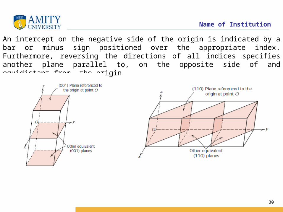
An intercept on the negative side of the origin is indicated by a bar or minus sign positioned over the appropriate index. Furthermore, reversing the directions of all indices specifies another plane parallel to, on the opposite side of and equidistant from, the origin

Name of Institution
31

Name of Institution
32
Determine the Miller indices for the plane shown in the accompanying sketch

Name of Institution
33
Since the plane passes through the selected origin O, a new origin must bechosen at the corner of an adjacent unit cell, taken as O’
The y and z axes intersections, referenced to the new origin O’, are -b and c/2, respectively
Thus, in terms of the lattice parameters a, b, and c, these intersections are
The reciprocals of these numbers are 0, -1, and 2
since all are integers, no further reduction is necessary
Finally, enclosure in parentheses yields
(012)

Name of Institution
34
These steps are briefly summarized below

Name of Institution
35
A plane is indicated by lines representing its intersections with the planes that constitute the faces of the unit cell or their extensions

Name of Institution
36
The indices are removed from the parentheses Reciprocals are taken
This means that the particular plane parallels the x axis while intersecting the y and z axes at b and c, respectively

Name of Institution
37
ATOMIC ARRANGEMENTS
The atomic arrangement for a crystallographic plane, which is often of interest, depends on the crystal structure. The (110) atomic planes for FCC and BCC crystal structures are represented below
(a)Reducedsphere FCC unit cell with (110) plane. (b) Atomic packing of an FCC (110) plane

Name of Institution
38
Reduced-sphere BCC unit cell with (110) plane. (b) Atomic packing of a BCC (110) plane
Name of Institution
39

Name of Institution
40
HEXAGONAL CRYSTALS
For crystals having hexagonal symmetry, it is desirable that equivalent planes have the same indices; as with directions, this is accomplished by the Miller–Bravais
This convention leads to the four-index (hkil) scheme, which is favored in most instances, since it more clearly identifies the orientation of a plane in a hexagonal crystal. There is some redundancy in that i is determined by the sum of h and k through

Name of Institution
41
CLOSE-PACKED CRYSTAL STRUCTURES
METALS
It may be remembered from the discussion on metallic crystal structures
that both face-centered cubic and hexagonal close-packed crystal structures have atomic packing factors of 0.74, which is the most efficient packing of equalized spheres or atoms

Name of Institution
42
In addition to unit cell representations
These two crystal structures may be described in terms of close-packed planes of atoms
Both crystal structures may be generated by the stacking of these close-packed planes on top of one another; the difference between the two structures lies in the stacking sequence.
Let the centers of all the atoms in one close-packed plane be labeled AAssociated with this plane are two sets of equivalent triangular depressions formed by three adjacent atoms, into which the next close-packed plane of atoms may rest

Name of Institution
43
Those having the triangle vertex pointing up are arbitrarily designated as Bpositions, while the remaining depressions are those with the down vertices, which are marked C
A second close-packed plane may be positioned with the centers of its atoms over either B or C sites; at this point both are equivalent
Suppose that the B positions are arbitrarily chosen; the stacking sequence is termed AB
The real distinction between FCC and HCP lies in where the third close-packed layer is positioned

Name of Institution
44

Name of Institution
45
For HCP, the centers of this layer are aligned directly above the original A positions. This stacking sequence, ABABAB . . . , is repeated over and overOf course, the ACACAC . . . arrangement would be equivalent
These close-packed planes for HCP are (0001)-type planes

Name of Institution
46
For the face-centered crystal structure, the centers of the third plane are situated over the C sites of the first plane
This yields an ABCABCABC . . . stacking sequence; that is, the atomic alignment repeats every third plane.

Name of Institution
47
CRYSTALLINE AND NONCRYSTAL L INE MATERI ALS
For a crystalline solid, when the periodic and repeated arrangement of atoms is perfect or extends throughout the entirety of the specimen without interruption, the result is a single crystal
Single Crystal
All unit cells interlock in the same way and have the same orientation. Single crystals exist in nature, but they may also be produced artificially. They are ordinarily difficult to grow, because the environment must be carefully controlled.

Name of Institution
48
Imperfections in Solids
• The properties of some materials are profoundly influenced by the presence of imperfections.
• Consequently, it is important to have a knowledge about the types of imperfections that exist, and the roles they play in affecting the behavior of materials.
• For a crystalline solid we have tacitly assumed that perfect order exists throughout the material on an atomic scale
• However, such an idealized solid does not exist; all contain large numbers of various defects or imperfections.
Name of Institution
49
• As a matter of fact, many of the properties of materials are profoundly sensitive to deviations from crystalline perfection;
• The influence is not always adverse, and often specific characteristicsare deliberately fashioned by the introduction of controlled amounts ornumbers of particular defects
• crystalline defect’’ is meant a lattice irregularity having one or more of its dimensions on the order of an atomic diameter

Name of Institution
50
Types of Imperfections
1)Thermal vibrations
2) Point defectsa) Vacanciesb) interstitial.
3. Line defectsa) Edge dislocationb)Screw dislocation
4. Surface defects (Interfacial defects)a) Grain boundariesb) Twin boundaries
5. Volume defects

Name of Institution
51
1) Thermal vibrations
• No crystal is rigid• Deformed by finite forces• Displace atoms from their ideal sites• Due to finite expenditure of energy• Frequency of vibration independent of temperature• But amplitude increases• Breaking of bond , melting then liquid

Name of Institution
52
1) Point defects
• The simplest of the point defects is a vacancy, or vacant lattice site, one normally occupied from which an atom is missing
• All crystalline solids contain vacancies and, in fact, it is not possible to create such a material that is free of these defects
Name of Institution
53
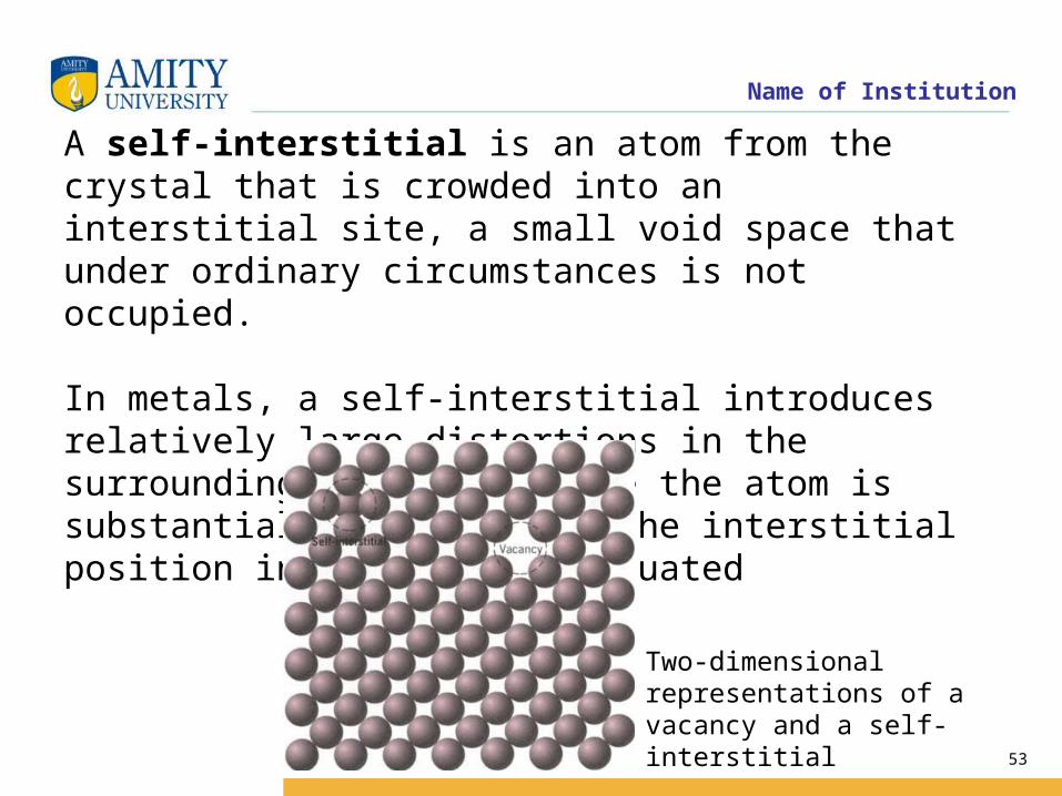
A self-interstitial is an atom from the crystal that is crowded into an interstitial site, a small void space that under ordinary circumstances is not occupied.
In metals, a self-interstitial introduces relatively large distortions in the surrounding lattice because the atom is substantially larger than the interstitial position in which it is situated
Two-dimensional representations of a vacancy and a self-interstitial
Name of Institution
54
DISLOCATIONS—LINEAR DEFECTS
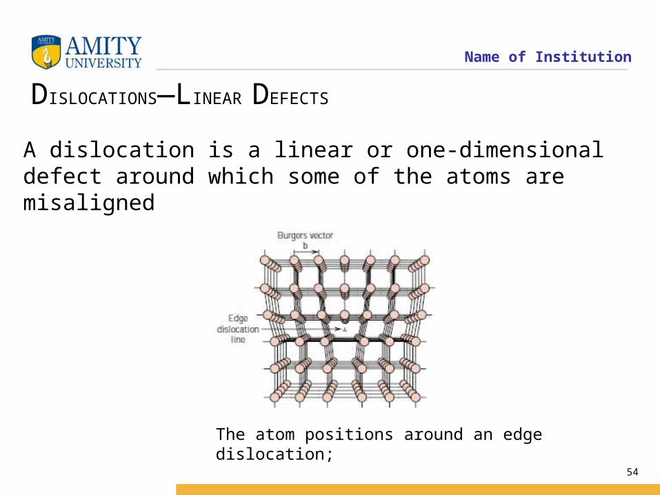
A dislocation is a linear or one-dimensional defect around which some of the atoms are misaligned
The atom positions around an edge dislocation;

Name of Institution
55
Edge dislocation or Taylor-Orowan dislocation is characterized by a Burger’s vector that is perpendicular to the dislocation line. It may be described as an edge of an extra plane of atoms within a crystal structure. Thus regions of compression and tension are associated with an edge dislocation. Because of extra incomplete plane of atoms, the atoms above the dislocation line are squeezed together and are in state of compression whereas atoms below are pulled apart and experience tensile stresses

Name of Institution
56
an extra portion of a plane of atoms, or half-plane, the edge of which terminates within the crystal. This is termed an edge dislocation;
it is a linear defect that centers around the line that is defined along the end of the extra half-plane of atoms
An edge dislocation may also be formed by an extra half-plane of atoms that is included in the bottom portion of the crystal; its designation is a .

Name of Institution
57
Screw dislocation or Burgers dislocation has its dislocation line parallel to the Burger’s vector.. Screw dislocations result when displacing planes relative to each other through shear.
Shear stresses are associated with the atoms adjacent to the screw dislocation; therefore extra energy is involved as it is in the case of edge dislocations

Name of Institution
58
INTERFACIAL DEFECTS( Surface defects):
Interfacial defects can be defined as boundaries that have two dimensional imperfections in crystalline solids, and have different crystal structures and/or crystallographic orientations on either side of them.
They refer to the regions of distortions that lie about a surface having thickness of a few atomic diameters
Name of Institution
59
EXTERNAL SURFACES
One of the most obvious boundaries is the external surface, along which the crystal structure terminates. Surface atoms are not bonded to the maximum number of nearest neighbors, and are therefore in a higher energy state than the atoms at interior positions. The bonds of these surface atoms that are not satisfied give rise to a surface energy, expressed in units of energy per unit area (J/m2 or erg/cm2).
To reduce this energy, materials tend to minimize, if at all possible, the total surface area. For example, liquids assume a shape having a minimum area—the droplets become spherical. Of course, this is not possible with solids, which are mechanically rigid.

Name of Institution
60
GRAIN BOUNDARIES
Grain boundaries: Crystalline solids are, usually, made of number of grains separated by grain boundaries. Grain boundaries are several atoms distances wide, and there is mismatch of orientation of grains on either side of the boundary
Schematic presentation of grain boundaries
Name of Institution
61
Twin boundaries:
A twin boundary is a special type of grain boundary across which there is a specific mirror lattice symmetry; that is, atoms on one side of the boundary are located in mirror image positions of the atoms on the other side
The region of material between these boundaries is appropriately termed a twin.
Twins result from atomic displacements that are produced from applied mechanical shear forces (mechanical twins)

Name of Institution
62
A pair of twin boundaries

Name of Institution
63
Bulk or Volume defects
Volume defects as name suggests are defects in 3-dimensions. These include pores, cracks, foreign inclusions and other phases. These defects are normally introduced during processing and fabrication steps. All these defects are capable of acting as stress raisers, and thus deleterious to parent metal’s mechanical behavior. However, in some cases foreign particles are added purposefully to strengthen the parent material.
Name of Institution
64
X - ray diffraction is one of the earliest methods for studying the structure of solids. In the process of diffraction, electromagnetic waves of a given frequency but different phases interact to produce constructive interference (bright spots on the film exposed to the light) and destructive interference (dark spots). By a careful analysis of the diffraction patterns, very accurate values of the lattice parameters (unit cell dimensions) can be inferred.
X- ray diffractometers
When high energy electrons are incident on metallic surfaces they knock off the bound electrons from even the inner shells of the atoms. When electrons from the higher shells undergo a transition into the lower (now partially empty ) shells, X-rays are emitted.
Name of Institution
65
Suitable filters are used to obtain monochromatic beams of X-rays. The sample to be studied consists of either a powdered form of the solid or a single crystal. The Debye-Sherrer method is for powders. A photographic film is rolled over the sample and the diffraction pattern traces a cone around the incident beam. The crystallites in the powder are arranged in random directions. If the angle of incident light is on any plane, then the diffracted light is at an angle of 2 from the incident beam.
Bragg's Law
This is a simple and elegant law which is central to the analysis of diffraction data. This law relates the angle ( at which there is a maximum in diffracted intensity ) to the wavelength of X-rays and the inter-layer distance d between the planes of atoms / ions / molecules in the lattice

Name of Institution
66
The layers of atoms are indicated by the labels to the right of the lines. The Lattice points are denoted by solid circles. The dashed lines along the row of atoms are only for guiding the eyes. The rays R1 and R2 are parallel and they have the same phase till
they are at b and e respectively. The ray R2 traverses an additional distances efg. This
additional distance causes a phase difference between rays R1 and R2. If rays R1 and
R2 are at an angle of with respect to the atomic planes, then the angles e b f and f b g
are also and the path length ef and fg are both equal to d sin where d is the perpendicular distance between any two adjacent layers. For constructive interference between rays R1 and R2, the path difference between R1 and R2 has to be an integral
multiple of , the wavelength of X-rays used, i.e.
2 sind n
Name of Institution
67
The reflection of R2 is called a first order reflection as it is from the first inner layer. The ray R3 which is reflected by layer 3 is a second order reflection. The intensities of reflected light from the inner layers ( 3, 4 (not shown) and so on ) is much less and the major diffraction is brought out by the first inner layer. From the intense peaks of the diffraction patterns, the distances between various crystal planes can be determined. We now move on to the labeling of the lattice planes through Miller indices.