Embed Size (px)
Citation preview

Catalog 865-6
Modular Self-Contained Air Conditioning SystemsType: SWT Models: 023C–040C Size: 20 through 45 Tons

CAT 865-6 • SELF-CONTAINED AIR CONDITIONER 2 www.DaikinApplied.com
Table of ConTenTs
Introduction . . . . . . . . . . . . . . . . . . . . . . . . . . . . . . . . . . 3Continued Leadership in Floor-By-Floor, Self-Contained System Designs. . . . . . . . . . . . . . . . . . . . . 3
Agency Listed . . . . . . . . . . . . . . . . . . . . . . . . . . . . . 3Nomenclature. . . . . . . . . . . . . . . . . . . . . . . . . . . . . . 3
Daikin Self-Contained VAV Systems . . . . . . . . . . . . . . 4System Performance Providing Tenant Comfort and Operating Economy . . . . . . . . . . . . . . . . . . . . . . . . . 4
Design Features . . . . . . . . . . . . . . . . . . . . . . . . . . . . . . 6Cabinet, Casing and Frame . . . . . . . . . . . . . . . . . . . . 6Modular Design . . . . . . . . . . . . . . . . . . . . . . . . . . . . . . 6Condensing Section . . . . . . . . . . . . . . . . . . . . . . . . . . 6Cooling Coil Section . . . . . . . . . . . . . . . . . . . . . . . . . . 7Heating Section. . . . . . . . . . . . . . . . . . . . . . . . . . . . . . 7
Electric Heat. . . . . . . . . . . . . . . . . . . . . . . . . . . . . . . 7Hot Water Heat . . . . . . . . . . . . . . . . . . . . . . . . . . . . 7
Supply Fan Section . . . . . . . . . . . . . . . . . . . . . . . . . . . 7Economizer Options . . . . . . . . . . . . . . . . . . . . . . . . . . 8
Waterside Economizer . . . . . . . . . . . . . . . . . . . . . . . 8Airside Economizer . . . . . . . . . . . . . . . . . . . . . . . . . 8Condenser Head Pressure Control . . . . . . . . . . . . . 9
Filter Section . . . . . . . . . . . . . . . . . . . . . . . . . . . . . . . . 9Electrical . . . . . . . . . . . . . . . . . . . . . . . . . . . . . . . . . . . 9Controls. . . . . . . . . . . . . . . . . . . . . . . . . . . . . . . . . . . 10
MicroTech III Unit Controls. . . . . . . . . . . . . . . . . . . 10Protocol Selectability™ Feature . . . . . . . . . . . . . . . 10
Auxiliary Control Options. . . . . . . . . . . . . . . . . . . . . . 10System Flexibility . . . . . . . . . . . . . . . . . . . . . . . . . . . . 11
Selection/Application Flexibility . . . . . . . . . . . . . . . . . 11Modular Construction. . . . . . . . . . . . . . . . . . . . . . . 11Optimal Discharge Air Temperature: . . . . . . . . . . . 11Arrangement Flexibility . . . . . . . . . . . . . . . . . . . . . 12Filtration Flexibility . . . . . . . . . . . . . . . . . . . . . . . . . 12Energy Saving Economizer Flexibility . . . . . . . . . . 12Heating Flexibility. . . . . . . . . . . . . . . . . . . . . . . . . . 12Controllers . . . . . . . . . . . . . . . . . . . . . . . . . . . . . . . 12Refrigerant R-407C . . . . . . . . . . . . . . . . . . . . . . . . 12
MicroTech III Unit Controller . . . . . . . . . . . . . . . . . . . 13Open Choices Benefits for Easy Integration . . . . . 13Components. . . . . . . . . . . . . . . . . . . . . . . . . . . . . . 13
Application Considerations . . . . . . . . . . . . . . . . . . . . 21General . . . . . . . . . . . . . . . . . . . . . . . . . . . . . . . . . . . 21Unit Location . . . . . . . . . . . . . . . . . . . . . . . . . . . . . . . 21Acoustical Considerations. . . . . . . . . . . . . . . . . . . . . 21Recommended Clearances. . . . . . . . . . . . . . . . . . . . 22Equipment Room . . . . . . . . . . . . . . . . . . . . . . . . . . . 22Ductwork . . . . . . . . . . . . . . . . . . . . . . . . . . . . . . . . . . 22
Return Duct . . . . . . . . . . . . . . . . . . . . . . . . . . . . . . 22Supply Duct . . . . . . . . . . . . . . . . . . . . . . . . . . . . . . 22Duct Protection . . . . . . . . . . . . . . . . . . . . . . . . . . . 23Vibration Isolation. . . . . . . . . . . . . . . . . . . . . . . . . . 23
Condenser Water Piping . . . . . . . . . . . . . . . . . . . . . . 23Head Pressure Control . . . . . . . . . . . . . . . . . . . . . 23
Variable Air Volume . . . . . . . . . . . . . . . . . . . . . . . . . . 23Variable Frequency Drives . . . . . . . . . . . . . . . . . . . . 23Duct Static Pressure Sensor Placement . . . . . . . . . 23Zone Sensor Placement . . . . . . . . . . . . . . . . . . . . . . 24System Operating Limits . . . . . . . . . . . . . . . . . . . . . . 24
Airflow . . . . . . . . . . . . . . . . . . . . . . . . . . . . . . . . . . 24Fan Heat . . . . . . . . . . . . . . . . . . . . . . . . . . . . . . . . 24Condenser Water Flow . . . . . . . . . . . . . . . . . . . . . 25Coil Freeze Protection . . . . . . . . . . . . . . . . . . . . . . 25Air Density Correction . . . . . . . . . . . . . . . . . . . . . . 25Unit Wiring . . . . . . . . . . . . . . . . . . . . . . . . . . . . . . . 25
Selection Procedure . . . . . . . . . . . . . . . . . . . . . . . . . . 26Physical Data . . . . . . . . . . . . . . . . . . . . . . . . . . . . . . . 28Performance Data . . . . . . . . . . . . . . . . . . . . . . . . . . . . 29
Unit Efficiency Ratings . . . . . . . . . . . . . . . . . . . . . . . 29Correction Multipliers . . . . . . . . . . . . . . . . . . . . . . . 29DX Cooling Capacity Data . . . . . . . . . . . . . . . . . . . 29Waterside Economizer Capacity . . . . . . . . . . . . . . 32Heating Capacity Data . . . . . . . . . . . . . . . . . . . . . . 34Component Pressure Drops . . . . . . . . . . . . . . . . . 35
Fan Curves . . . . . . . . . . . . . . . . . . . . . . . . . . . . . . . . 37Dimensional Data . . . . . . . . . . . . . . . . . . . . . . . . . . . . 40Electrical Data . . . . . . . . . . . . . . . . . . . . . . . . . . . . . . . 43
Supply Power Wiring. . . . . . . . . . . . . . . . . . . . . . . . . 44Unit Weights . . . . . . . . . . . . . . . . . . . . . . . . . . . . . . . . 45Engineering Guide Specifications . . . . . . . . . . . . . . 46
InTroduCTIon
www.DaikinApplied.com 3 CAT 865-6 • SELF-CONTAINED AIR CONDITIONER
InTroduCTIon
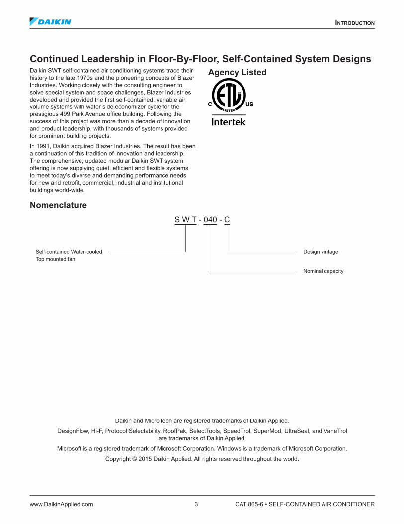
Continued Leadership in Floor-By-Floor, Self-Contained System DesignsDaikin SWT self-contained air conditioning systems trace their history to the late 1970s and the pioneering concepts of Blazer Industries. Working closely with the consulting engineer to solve special system and space challenges, Blazer Industries developed and provided the first self-contained, variable air volume systems with water side economizer cycle for the prestigious 499 Park Avenue office building. Following the success of this project was more than a decade of innovation and product leadership, with thousands of systems provided for prominent building projects.
In 1991, Daikin acquired Blazer Industries. The result has been a continuation of this tradition of innovation and leadership. The comprehensive, updated modular Daikin SWT system offering is now supplying quiet, efficient and flexible systems to meet today’s diverse and demanding performance needs for new and retrofit, commercial, industrial and institutional buildings world-wide.
Agency Listed
Nomenclature
Daikin and MicroTech are registered trademarks of Daikin Applied.
DesignFlow, Hi-F, Protocol Selectability, RoofPak, SelectTools, SpeedTrol, SuperMod, UltraSeal, and VaneTrol are trademarks of Daikin Applied.
Microsoft is a registered trademark of Microsoft Corporation. Windows is a trademark of Microsoft Corporation.
Copyright © 2015 Daikin Applied. All rights reserved throughout the world.
S W T - 040 - C
Self-contained Water-cooled Top mounted fan
Design vintage
Nominal capacity

CAT 865-6 • SELF-CONTAINED AIR CONDITIONER 4 www.DaikinApplied.com
InTroduCTIon
Daikin Self-Contained VAV SystemsSystem Performance Providing Tenant Comfort and Operating EconomySince the introduction of self-contained systems in the late 1970s, the industry has seen this concept grow into one of the most widely specified systems for new office buildings, for retrofitting existing structures, and for institutional, industrial, and other specialized applications. The reason is simple: system performance. Designed specifically to satisfy growing system retrofit needs, Daikin SWT self-contained VAV systems provide the total performance advantage of:
• Modular construction — Prime candidate for building renovation — Special 34.5" maximum section width fits through a 3' door frame
— Refrigerant lines always remain intact — Requires minimum floor area when reassembled — Retrofit alternative where existing chiller cannot be accessed for replacement
• Comfort and Redundancy — Occupants enjoy individual control over comfort conditions and off-hour system operation.
— Tenants benefit from their individual efforts to control energy costs.
— Routine service is located where it minimizes tenant inconvenience.
— Individual or dual systems per floor provide system redundancy and standby.
• Economical First Cost — VAV system flexibility uses building diversity to reduce system tonnage and first cost.
— Factory-packaged concept reduces field labor, installation time and expense.
— No expensive chilled water piping or chiller room. — Individually tested, factory-designed systems reduce startup and installation expense.
— Reduced penthouse and equipment room requirements.
— Centralized condenser water and condensate piping and streamlined system layout.
— Modular units design make renovation projects easier since individual section designed for narrow hallways, elevators and doorways.
• Energy Efficient System — Reduces fan kW and operating costs at part load conditions.
— Savings maximized through use of variable speed fan control.
— Individual zone control.
• Improving Indoor Air QualityFor better filtration filter selection flexibility includes:
— MERV 7, 8, 11, 13, or 14 options with and without pre-filter. Microbial-resistant filter option is also an available option.
— Featured Double-wall panel construction that eliminates fibers in the supply air stream and is easy to clean.
— Provided with double-sloped, galvanized or stainless steel drain pans eliminate stagnant water and minimizes bacterial growth.
• Quiet System Operation — Provided by structural quality and specialized design. — Recognized for quiet operation by renowned U.S. acoustical consultants.
— With an airfoil plenum fan for better acoustics and efficiency
— Unit plenum with sound baffles is an available for sound sensitive job
• Free Cooling — Water or air economizer capability for optimized energy savings.
— Economizer reduces compressor operating hours and energy costs.
— Year-round “free cooling” capability.

InTroduCTIon
www.DaikinApplied.com 5 CAT 865-6 • SELF-CONTAINED AIR CONDITIONER
• Efficient Part Load Operation — System energy at part load operation is more efficient than to central chilled water systems.
— Multiple systems and compressors versus a single, large central plant.
— Efficient and reliable system for partial occupancy and after hours operation.
— Operates only the system(s) on the floor(s) requiring after hours use.
• Economical Integrated or Stand Alone DDC controls — Monitoring and diagnostics reduce the potential for expensive field repairs.
— Industry leading Protocol Selectability™ feature provides effective BAS selection flexibility.
• Maintenance Costs Reduction — No complicated central chiller plant to maintain. — Service and maintenance are performed out of the occupied space.
— Control and product reliability functions designed by the equipment manufacturer for single source responsibility and improved reliability.
• System Versatility — Applicable to schools, offices, shopping centers, manufacturing facilities, etc.
— Prime candidate for floor by floor building renovation. — Retrofit alternative where existing chiller cannot be accessed for replacement
• System savings of advanced MicroTech® III DDC control system
— Monitoring and diagnostics reduce the potential for expensive field repairs
— Industry leading Protocol Selectability™ feature provides effective BAS selection flexibility
• Reduced system maintenance and service costs — No complicated central chiller plant to maintain — Service and maintenance are performed out of the occupied space
— Control and product reliability functions designed by the equipment manufacturer for single source responsibility and improved reliability

CAT 865-6 • SELF-CONTAINED AIR CONDITIONER 6 www.DaikinApplied.com
desIgn feaTures
desIgn feaTures
Cabinet, Casing and FrameFor vibration control and rigging strength, the SWT unit base is constructed of welded structural steel channel and 10-gauge galvanized steel panels. Heavy-duty lifting brackets are strategically placed for balanced cable or chain hook lifting.
For long equipment life, unit exterior panels are constructed of heavy gauge, pre-painted, galvanized steel. The complete cabinet, frame and access panels are insulated with 1 inch thick, 1.0 lb. dual density insulation. Double wall construction is available to enhance performance and satisfy IAQ requirements.
For maintenance and service ease, system components are strategically located for ease of inspection and maintenance. Refrigeration components are positioned out of the airstream so adjustments and readings can be made without disrupting system operation. Service friendly access is made through heavy-duty, conveniently removable panels. Access panels are set on neoprene gaskets to prevent air leakage.
Modular DesignThe SWT unit is easily disassembled into three compact sections; main cooling/heating, filter/waterside economizer and fan. See “Modular Construction” under “System Flexibility” on page 11.
Figure 1: SWT Cabinet
Condensing SectionMultiple compressors are featured in all SWT systems for efficient system part load control, quiet operation and system redundancy. Compressors are quiet, reliable hermetic scroll type complete with sightglass, anti-slug protection, and motor overload protection. Suction and discharge service valves, with gauge ports, are available on each compressor. Individual branch circuit fusing protects each compressor. The unit’s MicroTech III control system incorporates timing functions to prevent compressor short cycling. All compressors are resiliently mounted to minimize any noise transmission. The condensing section is insulated and segregated from the air handling section of the unit to avoid transmission of noise to the circulated air stream.
Figure 2: Scroll Compressor
Each compressor is on an independent refrigerant circuit complete with filter-drier, liquid moisture indicator/sightglass, thermal expansion valve capable of modulation from 100-25% of its rated capacity, liquid line shutoff valve with charging port, high pressure relief device and high and low pressure cutouts. If any compressor is made inoperable, the remaining compressors are still allowed to operate.
The unit’s MicroTech III controller senses entering condenser water temperature and prevents mechanical cooling when the temperature falls below an adjustable setpoint value, minimum 55°F. For systems which will see entering condenser water temperatures below 55°F, a waterside economizer or head pressure activated control valve is available.
SWT water cooled condensers feature a mechanically cleanable, all copper design using the same high performance enhanced tubing found in modern centrifugal chillers. Liquid refrigerant subcooling is provided as standard. Each condenser is part of an independent refrigerant circuit and comes complete with a spring loaded high pressure relief valve. All condensers are independently leak tested. All completed units are leak tested, evacuated and shipped with a full operating charge of R-407C and oil.
Fan Section
Filter / Waterside Economizer Section Main Heating /
Cooling Section
desIgn feaTures
www.DaikinApplied.com 7 CAT 865-6 • SELF-CONTAINED AIR CONDITIONER
The condenser assembly and all factory water piping is rated for a waterside working pressure of 400 psig and is factory leak tested before shipment. Condenser water channels are mechanically cleanable by removing brass service plugs that are sealed with reusable o-ring gaskets. Main interconnecting condenser water headers include vent and drain plugs and a large cleanout plug for removing debris dislodged during cleaning. Condensers are factory piped for a single condenser water supply and a single condenser water return connection.
Both right-hand and left-hand piping locations are available.
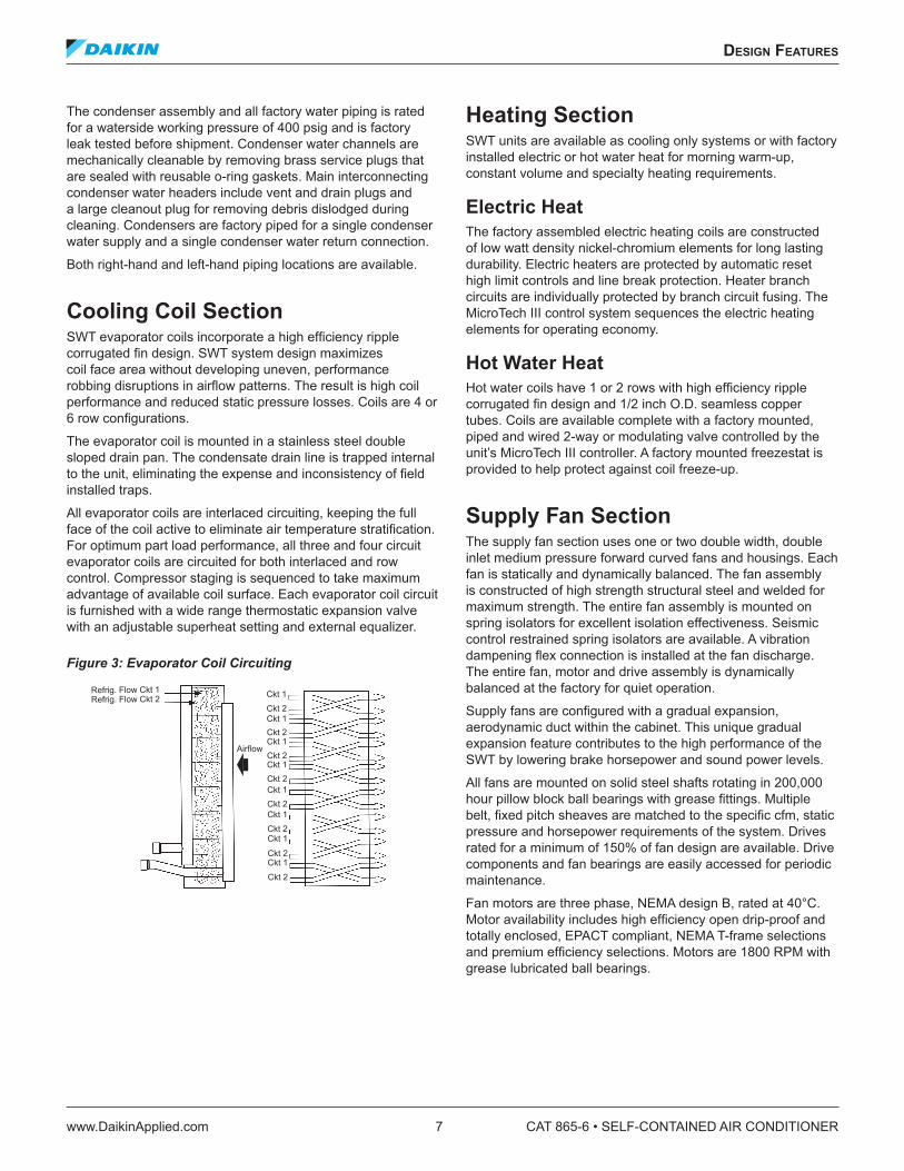
Cooling Coil SectionSWT evaporator coils incorporate a high efficiency ripple corrugated fin design. SWT system design maximizes coil face area without developing uneven, performance robbing disruptions in airflow patterns. The result is high coil performance and reduced static pressure losses. Coils are 4 or 6 row configurations.
The evaporator coil is mounted in a stainless steel double sloped drain pan. The condensate drain line is trapped internal to the unit, eliminating the expense and inconsistency of field installed traps.
All evaporator coils are interlaced circuiting, keeping the full face of the coil active to eliminate air temperature stratification. For optimum part load performance, all three and four circuit evaporator coils are circuited for both interlaced and row control. Compressor staging is sequenced to take maximum advantage of available coil surface. Each evaporator coil circuit is furnished with a wide range thermostatic expansion valve with an adjustable superheat setting and external equalizer.
Figure 3: Evaporator Coil Circuiting
Heating SectionSWT units are available as cooling only systems or with factory installed electric or hot water heat for morning warm-up, constant volume and specialty heating requirements.
Electric HeatThe factory assembled electric heating coils are constructed of low watt density nickel-chromium elements for long lasting durability. Electric heaters are protected by automatic reset high limit controls and line break protection. Heater branch circuits are individually protected by branch circuit fusing. The MicroTech III control system sequences the electric heating elements for operating economy.
Hot Water HeatHot water coils have 1 or 2 rows with high efficiency ripple corrugated fin design and 1/2 inch O.D. seamless copper tubes. Coils are available complete with a factory mounted, piped and wired 2-way or modulating valve controlled by the unit’s MicroTech III controller. A factory mounted freezestat is provided to help protect against coil freeze-up.
Supply Fan SectionThe supply fan section uses one or two double width, double inlet medium pressure forward curved fans and housings. Each fan is statically and dynamically balanced. The fan assembly is constructed of high strength structural steel and welded for maximum strength. The entire fan assembly is mounted on spring isolators for excellent isolation effectiveness. Seismic control restrained spring isolators are available. A vibration dampening flex connection is installed at the fan discharge. The entire fan, motor and drive assembly is dynamically balanced at the factory for quiet operation.
Supply fans are configured with a gradual expansion, aerodynamic duct within the cabinet. This unique gradual expansion feature contributes to the high performance of the SWT by lowering brake horsepower and sound power levels.
All fans are mounted on solid steel shafts rotating in 200,000 hour pillow block ball bearings with grease fittings. Multiple belt, fixed pitch sheaves are matched to the specific cfm, static pressure and horsepower requirements of the system. Drives rated for a minimum of 150% of fan design are available. Drive components and fan bearings are easily accessed for periodic maintenance.
Fan motors are three phase, NEMA design B, rated at 40°C. Motor availability includes high efficiency open drip-proof and totally enclosed, EPACT compliant, NEMA T-frame selections and premium efficiency selections. Motors are 1800 RPM with grease lubricated ball bearings.
Refrig. Flow Ckt 1Refrig. Flow Ckt 2
Ckt 2
Ckt 1
Ckt 1
Ckt 1
Ckt 1
Ckt 1
Ckt 1
Ckt 1
Ckt 1
Ckt 2
Ckt 2
Ckt 2
Ckt 2
Ckt 2
Ckt 2
Ckt 2
Airflow

CAT 865-6 • SELF-CONTAINED AIR CONDITIONER 8 www.DaikinApplied.com
desIgn feaTures
Energy saving advanced technology variable frequency drive (VFD) fan speed control is available with the convenience and cost savings of factory mounting and testing. All VFD selections are plenum rated. A manually activated bypass contactor is available to allow system operation even in the event of drive service.
MicroTech III controls provide advanced duct static pressure control. Static pressure can be controlled by either a single or two duct static pressure sensors. All VAV systems include an adjustable duct high-limit switch to protect duct work from excessive pressure.
Figure 4: Supply Fan
Economizer OptionsWaterside EconomizerAn energy saving, waterside economizer package is available on all units. The complete economizer system is factory mounted including a 4-row mechanically cleanable coil, control valves and factory piping complete with cleanouts. The complete economizer package is rated for up to 400 psig waterside working pressure and the entire coil and piping assembly is factory leak tested.
Economizer operation is controlled by the SWT’s MicroTech III controller to maximize free cooling potential. Economizer operation is enabled whenever the available cooling tower water temperature is less than the unit entering air temperature by a field adjustable value, generally 5-7°F. The economizer control valve modulates in response to the cooling load. Control valve operation can be selected to (1) maintain full flow through the unit at all times or (2) isolate the unit from the condenser water loop when there is no call for cooling to save energy with a variable pumping system. (Economizer control valves do not eliminate the need to provide unit isolation valves.) To extend free cooling savings, mechanical cooling is enabled during economizer operation. Only when the economizer valve is driven 90% open and the cooling load is not satisfied, will compressors be staged to maintain cooling setpoint. Economizer control will maintain full free cooling capability until disabled by the economizer changeover setpoint. A factory mounted freezestat is provided to help protect against coil freeze-up.
Airside EconomizerAn airside economizer control package is available for controlling field installed mixing dampers capable of 100% outside airflow. Economizer operation will be controlled by the SWT’s MicroTech III controller to maximize free cooling potential. Economizer operation is enabled whenever an outside air (or comparative) enthalpy sensor or outside air temperature sensor indicates that outside air is suitable for free cooling. The economizer damper control actuator shall modulate in response to the cooling load. The outside air damper will be positioned to maintain minimum ventilation requirements when economizer is disabled.
To extend free cooling savings, mechanical cooling is enabled during economizer operation. Only when the economizer damper is driven 90% open and the cooling load is not satisfied, will compressors be staged to maintain cooling setpoint. Economizer control will maintain full free cooling capability until disabled by the economizer changeover setpoint. Factory supplied mixing boxes are available for airside economizer use using the Daikin Vision™ air handling unit platform.

desIgn feaTures
www.DaikinApplied.com 9 CAT 865-6 • SELF-CONTAINED AIR CONDITIONER
Condenser Head Pressure ControlFor applications where a waterside economizer package is not being used and entering condenser water temperatures can be less than 55°F, condenser head pressure control is required. To satisfy these applications, a factory installed 2-way, head pressure activated control valve is available to maintain unit operation with entering condenser water temperatures as low as 40°F.
Figure 5: Mechanically Cleanable Waterside Economizer Coil
Figure 6: Economizer Piping
Filter SectionAll SWT units are provided, as standard, with 4" deep extended media 30% efficient filters. For higher filtration requirements, 65% and 85% AmericanAirFilter™ Varicel® filters are available with an optional pre-filter rack. Filters are removable from the rear of the unit or through hinged and latched side access doors on the filter box.
ElectricalEach unit is completely wired and tested at the factory prior to shipment. Wiring complies with NEC requirements and conforms to all applicable UL standards for reliability and safety. All electrical components are labeled according to the electrical diagram and are UL recognized whenever applicable. Line voltage components and wiring are physically separated from the low voltage control system.
The supply fan motor, compressor motors and electric heat all have individual branch circuit fuse protection. Control circuit power is supplied through a factory installed, low voltage transformer. The supply fan motor circuit includes a three phase contactor and ambient compensated overload protection with manual reset. Each refrigerant circuit includes both a high and low pressure cutout switch and a coil frost protection thermostat.
A terminal block is provided for the single, main power connection and a terminal board is provided for low voltage control wiring. A factory mounted, non-fused main circuit interrupter is available for disconnecting the main electrical power to the unit. The switch is visible, located at the front of the unit, and is accessible without unit penetration. Dual power blocks or disconnect switches are available to accommodate requirements for standby, emergency power supplies.

CAT 865-6 • SELF-CONTAINED AIR CONDITIONER 10 www.DaikinApplied.com
desIgn feaTures
ControlsMicroTech III Unit ControlsAll SWT units feature advanced MicroTech III DDC controls to provide all temperature and static pressure control, product reliability control functions, system time clock and all monitoring and diagnostics. Each MicroTech III control system features a human interface with English language display for fast system diagnostics and adjustments. The complete control system is factory installed and commissioned prior to shipment.
Protocol Selectability™ FeatureAll MicroTech III control systems have Daikin’s exclusive Protocol Selectability feature. MicroTech III control systems can be factory configured for standalone operation or for incorporation into an independent building automation system using either the BACnet® MS/TP, BACnet® /IP or LonTaLk® protocols.
Auxiliary Control OptionsCondenser Water Flow Switch – A factory installed, flow switch is available to verify water flow status at each unit. Compressor operation is disabled and an alarm signal provided if condenser water flow is lost. Unit operation is restored when water flow has again been sensed. Water flow status is displayed at the MicroTech III control’s plain language screen.
Freezestat – A nonaveraging type freezestat is available factory installed on the entering face of the economizer coil. Upon sensing a potential freeze condition, the unit supply air fan is shut down, the economizer (and heating) valve drives to the full open position and an alarm signal is provided. Unit operation is restored following the manual reset of the freezestat.
Phase Failure/Undervoltage Protection – Factory installed phase failure/under voltage protection is available to protect three phase motors from damage due to single phasing, phase reversal and low voltage conditions.
Individual Unit Factory Test – All SWT units are provided completely factory assembled, piped, wired, tested, and shipped in one piece. Each unit undergoes a factory test that includes:
• Dynamic trim balance of the completed fan assembly• Run check of all electrical components, alarms and
shutdowns, including proper control sequencing• Pressure test, at rated pressure, of refrigerant coils, water
coils and condensers prior to assembly• Final leak check of the completed refrigerant circuits• Final leak check of the completed water circuit• Compressor run check
Verification of factory run test is available at time of unit shipment.

sysTem flexIbIlITy
www.DaikinApplied.com 11 CAT 865-6 • SELF-CONTAINED AIR CONDITIONER
sysTem flexIbIlITy
Selection/Application FlexibilityAlong with providing high quality and state-of-the-art innovation, SWT self-contained systems emphasize system flexibility, flexibility not even considered by the competition. Daikin SWT systems offer customized flexibility to satisfy a wide range of diverse applications.
Nominal cooling capacities range from 15 to 45 tons and all units feature a 6 row evaporator coil. In addition, all units offer multiple compressor selections to meet exacting system requirements. Many standard compressor/coil capacity selections are available. The flexibility to optimize the self-contained system to fit the application is a Daikin SWT advantage. Available system applications include:
• VAV discharge air temperature control with static pressure control
• Discharge air temperature control with constant air volume
• Constant volume, zone temperature control• 100% outside air control• Zone VAV Control
In addition to compressor/coil flexibility, SWT systems offer double width, double inlet, forward curved fans with factory mounted variable frequency drives for maximizing VAV system fan performance. High efficiency fan capability coupled with extensive compressor flexibility can provide the right system selection for the application.
Modular ConstructionThe SWT unit has been designed with the flexibility to be easily disassembled into three compact sections. The three sections are the main cooling/heating, filter/waterside economizer and fan sections. Whereas most competitive products require removal of the door frame, each SWT section has a maximum width of 34.5", including fastener heads, and can fit through standard 3’ steel door frames.
The system installer is able to break the unit down into its three main sections without breaking any refrigerant lines. All SWT refrigerant lines remain intact, contained in the main cooling/heating section. This SWT feature can add up to substantial savings by avoiding the field expense to braze, evacuate and charge each refrigerant circuit.
Optimal Discharge Air Temperature:More and more system engineers are designing optimal discharge air temperature systems to improve system performance and system first cost, and the Daikin SWT provides the flexibility to do it successfully. Optimal discharge air temperature systems are designed to provide unit leaving air temperature selections of 52–53°F versus more conventional systems that supply air at temperatures closer to 58°F. This 5–6°F reduction in air temperature to the room diffusers can subsequently reduce the required supply air volume to the room by 20-25%.
The benefits of optimal discharge air temperature systems become quite apparent with a look at the advantages offered with reduced airflow:
• Reduced supply air CFM reduces first cost and installation cost by allowing smaller duct sizes and a smaller air distribution system.
• Reduced supply air CFM reduces fan BHP requirements. Depending on changes in duct size and the resulting total static pressure, a 20% reduction in supply air CFM can reduce the fan BHP requirements by 25% or more.
• Reduced supply air CFM provides reduced fan sound power generation and a quieter room environment.
• Reduced supply air CFM can often reduce the equipment room size due to the use of a physically smaller unit size.
Figure 7: Modular Construction
Fan Section
Main Heating / Cooling Section
Optional Hot Water Coil Connections
Condensate Drain
Filter / Waterside Economizer Section
Water In
Water Out
CAT 865-6 • SELF-CONTAINED AIR CONDITIONER 12 www.DaikinApplied.com
sysTem flexIbIlITy
Arrangement FlexibilityAll SWT systems offer the flexibility of right-hand and left-hand piping arrangements and front and rear fan discharge orientations. Piping and fan arrangement flexibility can simplify mechanical equipment room arrangement, improve installed cost and improve total system performance.
Filtration FlexibilitySWT systems are offered with 4 inch, 30% efficient pleated filters as standard. 4 inch, 65% efficient pleated filters and 4 inch, 85% efficient filters with pre-filters are also available.
Energy Saving Economizer FlexibilityTo improve system operating performance, all SWT systems offer complete factory mounted and controlled waterside economizer capability. Each waterside economizer system includes a 4 row, mechanically cleanable coil with dual, two-way control valves to allow use in either a constant or variable volume pumping system. In addition, units can be applied with air economizer cycles with integrated factory control.
Heating FlexibilityA variety of heating media is offered with each SWT system. Hot water coils with modulating valve and actuator are available along with staged electric heat to provide heating control in a variety of applications.
ControllersMicroTech III DDC control systems provide constant volume, variable air volume, 100% outside air, and/or zone VAV control flexibility. Each MicroTech III control system comes with a control screen conveniently mounted on the front of the unit to allow easy adjustment and monitoring of control functions. And with its easy to follow and read English language menus and data displays, it simply encourages and invites the operator to take advantage of its many capabilities.
Protocol Selectability FeatureAll MicroTech III control systems have Daikin’s exclusive Protocol Selectability feature. MicroTech III control systems can be factory configured for standalone operation or for incorporation into an independent building automation system using either the BACnet® MS/TP, BACnet® /IP or LonTaLk® protocols.
Summary of Available Options:• Multiple compressor/coil capacity selections• Multiple control options: VAV, CV, 100% OA,
dehumidification• Non-fused main power disconnect switch• Dual non-fused main disconnect switches• Non-averaging freezestat for hot water, or waterside
economizer coil protection• Unit phase failure/under voltage protection• Premium efficiency fan motors• Condenser water flow switch• 4-row waterside economizer system• Air cycle economizer system• Modulating hot water heat• Staged electric heat• Factory mounted and controlled variable frequency drives• High efficiency filtration options• Rightand left-hand piping selections• Front and back fan discharge arrangements• Head pressure control valve• Special coil coatings• Double wall cabinet construction• Seismic fan isolation• R407C refrigerant
Refrigerant R-407CDaikin SWT units with independent refrigerant circuits are available with non-ozone depleting R-407C refrigerant.
Features• HFC-407C refrigerant is environmentally friendly with
zero ozone depleting allowance (ODP).• ASHRAE Standard 34, Designation and Safety
Classification of Refrigerants, classifies HFC-407C as an A1 (lower toxicity—no flame propagation) refrigerant.
• Units are factory engineered for proper cooling performance using R-407C.
• Units are factory charged with R-407C and synthetic oil (such as POE), and they include components and controls specifically tailored to R-407C.
• Units are factory tested prior to shipment.
Benefits• HFC-407C allows you to provide your tenants with a
comfortable building environment in an environmentally friendly way.
• With no phase out date for production of HFC-407C, a reliable supply should be available for the life of your equipment.

mICroTeCh III unIT ConTroller
www.DaikinApplied.com 13 CAT 865-6 • SELF-CONTAINED AIR CONDITIONER
mICroTeCh III unIT ConTroller
Daikin SWT systems continue to provide industry leading performance, equipped with a complete MicroTech III control system. In addition to providing stable, efficient temperature, and static pressure control, the controller is capable of providing comprehensive diagnostics, alarm monitoring, and alarm specific component shutdown if critical equipment conditions occur. The unit controllers are factory mounted and configured for stand-alone operation or integration with a building automation system (BAS) through an optional communication module with our Open Choices feature.
Figure 8: MicroTech III Controller
Open Choices Benefits for Easy IntegrationEasy, low cost integration into most building automation systems without costly gateway panels.
• Flexibility to select either BACnet® or LONWORKS® communication. Units are LonMark® 3.4 certified with the appropriate communications module for LONWORKS networks.
• Comprehensive unit control and status information is available at the BAS regardless of communication protocol.
• Long-term choices for equipment adds or replacements, and for service support.
• Flexible alarm notification and prioritization with Intrinsic Alarm Management (BACnet).
• Simplified BAS integration with the ability to set network parameters at the unit controller, reducing installation time and costs.
• Easy monitoring and troubleshooting of communication status from the unit controller to the BAS.
ComponentsEach SWT self-contained system is equipped with a complete MicroTech III unit control system that is preengineered, preprogrammed, and factory tested prior to shipment. Each of the MicroTech III unit control systems is composed of several components that are individually replaceable for ease of service.
These components include:
• Unit controller with user interface display and navigation wheel
• Optional expansion modules• Communication module (optional)• Pressure transducers• Unit-mounted temperature sensors• Zone temperature sensor packages• Humidity sensor
Main Control Board (MCB)The main control board (MCB) contains a microprocessor that is preprogrammed with the software necessary to control the unit. This provides that schedules, set points and parameters are not lost, even during a long-term power outage. The microprocessor board processes system input data and then determines and controls output responses. An RS-232 communication port is provided as standard to allow for direct or modem access with a PC-based service tool.
Expansion ModulesThese boards are used to expand the input and output capability of the unit controller. Each board communicates via serial data communications. These microprocessor based boards provide independent operation and alarm response even if communication is lost with the unit controller.
Communication ModuleAn optional communication module provides the means to factory or field configure MicroTech III unit controls for interoperability with an independent BAS. Communication modules are available to support industry recognized communication protocols including BACnet MS/TP, BACnet/ IP and LONWORKS.

CAT 865-6 • SELF-CONTAINED AIR CONDITIONER 14 www.DaikinApplied.com
mICroTeCh III unIT ConTroller
Keypad/DisplayAll MicroTech III unit controllers include a push/pull navigation wheel and display. The display is a supertwist nematic type with highly visible black characters on a yellow background. The 5-line by 22-character format allows for easy to understand plain English display messages. All operating conditions, system alarms, control parameters and schedules can be monitored from the keypad/display. If the correct password has been entered, any adjustable parameter or schedule can be modified from the keypad.
Figure 9: MicroTech III Keypad/DisplayMicroTech III Unit Controls
Temperature and Humidity SensorsWith the exception of the zone, outside air and return air sensors, all temperature sensors are factory installed and tested. Zone sensor packages are available to suit any application. A humidity sensor is available for field installation.
Static Pressure TransducersAll pressure transducers are factory installed and tested. Connection and routing of field-supplied sampling tubes is done at time of unit installation.
Zone Temperature SensorsTwo optional zone temperature sensors are available:
• Zone sensor with tenant override switch• Zone sensor with tenant override switch and remote set
point adjustment
Timed tenant override is a standard MicroTech III control feature.Zone sensors are required for the controller’s purge cycle, space reset of supply air set point, and night setback or setup features. All zone sensors are field installed with field wiring terminated at a separate, clearly marked terminal strip.
Stand-alone Controller FeaturesMicroTech III applied rooftop unit controls include all of the essential features required to make them capable of completely independent, stand-alone operation.
Internal Time ClockAn internal, battery-backed time clock is included in the MicroTech III unit controller. Current date and time can be quickly and easily set at the user interface keypad.
Internal ScheduleSeven daily schedules and one holiday schedule can be entered at the keypad of all unit controllers. For each of these eight schedules, one start and one stop time can be entered. Up to 10 holiday periods, of any duration, can be designated. The unit will automatically run according to the holiday schedule on the holiday dates. To handle special occasions, an additional ‘one event’ schedule can also be used.
In lieu of its internal schedule, the unit can be operated according to a network schedule from a BAS.
External Time Clock or Tenant Override InputAn input is supplied that can be used to accept a field wired start/stop signal from a remote source. An external time clock, a tenant override switch, or both may be connected. Whenever the external circuit is closed, the controller overrides the internal schedule (if activated) and places the unit into the occupied mode.
If the internal schedule or a BAS network schedule is used, field wiring is not required.
Timed Tenant OverrideOff-hour operation flexibility is a must in today’s office environments and even stand-alone MicroTech III controls handle it with ease. When unit operation is desired during unoccupied hours, initiate timed tenant override by pressing the tenant override button on either of the optional zone sensor packages. The unit then starts and runs in the occupied mode for a keypad-adjustable length of time (up to five hours). If the button is pressed again while the unit is operating, the timer resets to the full time allowance without interrupting unit operation. Tenant override operation also can be initiated by a BAS.
Three Remote Set Point Adjustment Options1. Remote user interface option (RUI).
2. Building automation system (BAS). See Open Choices Benefits for Easy Integration on page 13.
3. All constant air volume-zone temperature control (CAV-ZTC) unit controllers include an input that can be used to remotely adjust the zone cooling and heating set points. To use this feature, wire the optional zone sensor package with set point adjustment to the controller. The remote set point adjustment feature can be enabled or disabled from the keypad at any time. When enabled, remote set point adjustment is available even if the return temperature is selected to be the Control Temperature.

mICroTeCh III unIT ConTroller
www.DaikinApplied.com 15 CAT 865-6 • SELF-CONTAINED AIR CONDITIONER
Auto/Manual Operation SelectionAutomatic or manual operation can be controlled either remotely or at the keypad.
All controllers include three inputs that can be used to enable or disable cooling, heating, and fan operation from remote switches. With the “heat enable” and “cool enable” terminals, the operator can enable cooling, heating, or both as desired. Using the system “off” terminals, the operator can disable the fans, and thus the entire unit.
From the keypad, there are a variety of occupancy and auto! manual control mode selections available to the operator:
• Occupancy modes — Auto — Occupied — Unoccupied — Bypass (tenant override)
• Control modes — Off manual — Auto — Heat/cool — Cool only — Heat only — Fan only
Compressor Lead-lag SelectionAll unit controllers are capable of automatic compressor, lead-lag control.
Waterside Economizer ChangeoverOn units equipped with a waterside economizer package, the MicroTech III unit controller includes an internal changeover strategy that compares entering cooling tower water temperature to the unit’s mixed air temperature. If the entering water temperature is less than the mixed air temperature by a field-adjustable differential (typically 5°F to 7ºF), the economizer control valve modulates in response to the cooling load.
Airside Economizer Changeover SelectionOn units equipped with an economizer, there are three methods of determining whether the outdoor air is suitable for free cooling: two methods sense enthalpy (dry bulb temperature and humidity) and one senses outdoor air dry bulb temperature.
The two enthalpy changeover methods use external, factory installed controls. One compares the outdoor ambient enthalpy to a set point; the other is a solid state device that compares the outdoor ambient enthalpy to the return air enthalpy. This comparative enthalpy control can improve total economizer performance.
All unit controls include an internal dry bulb changeover strategy that can be selected at the keypad. When this method is selected, the controller compares the outdoor air dry-bulb temperature to a keypad programmable set point. The external enthalpy control input is then ignored.
Cooling and Heating Lockout ControlAll unit controls include separate keypad programmable set points for locking out mechanical cooling and heating. Mechanical cooling is locked out when the outdoor temperature is below the cooling lockout set point; heating is locked out when the outdoor temperature is above the heating lockout set point. This feature can save energy cost by eliminating unnecessary heating and cooling during warm-up or cool-down periods or when the outdoor air temperature is mild.
Night Setback and Setup ControlWhen one of the zone temperature sensors is connected to the unit controller, night setback heating and night setup cooling control are available. Separate, keypad programmable night heating and cooling set points are used to start the unit when necessary. After the unit starts, night setback and setup control is similar to normal occupied control except that the minimum outside air damper position is set to zero. If the outside air is suitable for free cooling, it is used during night setup operation.
Except for 100% outside air applications, night setback control is available even if the unit is not equipped with any heating equipment. When the space temperature falls to the night setback set point, the fans simply start and run until the temperature rises above the differential. This feature might be useful for applications that use, for example, ductmounted reheat coils.

CAT 865-6 • SELF-CONTAINED AIR CONDITIONER 16 www.DaikinApplied.com
mICroTeCh III unIT ConTroller
Morning Warm-up ControlIf the Control Temperature (space or return) is below set point when the unit enters the occupied mode, the morning warm-up control function will keep the outside air dampers closed while heat is supplied to satisfy set point. The outside air damper will remain closed until either the space temperature rises to the
heating set point or the keypad adjustable morning warm-up timer expires (default is 90 minutes). The morning warm-up timer supplies the minimum required amount of outdoor air after a certain time regardless of the space temperature.
Morning warm-up control is automatically included on all except 100% outside air units. It is available even if the unit is not equipped with any heating equipment, for applications that utilize, for example, duct-mounted reheat coils.
Condenser Head Pressure Control (units without waterside economizer only)Mechanical cooling is allowed whenever the entering cooling tower water temperature is 55ºF or warmer, without the use of head pressure control. When the entering water temperature is below 55ºF, a factory-installed and factorycontrolled two-way modulating head pressure control valve can be utilized. The regulating valve is controlled by the MicroTech III controller to maintain refrigerant head pressure.
Outdoor Air Purge Control (units with airside economizer only)Purge control is designed to take advantage of cool early morning outside air conditions. It starts the fans and modulates the economizer dampers to maintain occupied cooling requirements during unoccupied periods, if conditions are appropriate. This provides the opportunity to flush the space with fresh outdoor air prior to occupancy. Purge operation is possible only during a keypad-adjustable time window prior to occupancy (0 to 240 minutes). When the purge-cycle is active, mechanical cooling is disabled. To use the purge feature, connect one of the zone temperature sensors to the unit controller. Below is a description of purge control operation.
During the purge time window, the unit starts and runs whenever these three requirements are met:
• The space temperature must be warm enough to enable occupied cooling.
• The outside air enthalpy must be low enough to enable the economizer.
• The outside air temperature must be at least 3°F less than the space temperature.
When any one of these conditions is no longer true, the unit shuts down. As conditions allow, purge cycles the unit in this manner until it enters the occupied mode.
Proportional Integral (PI) ControlThe Proportional Integral (PI) control algorithm controls modulating actuators to maintain a measured variable (temperature or pressure) at or near its set point. For example, it controls economizer dampers to maintain the discharge cooling set point and it controls the supply fan variable frequency drives to maintain the duct static pressure set point. The integral control feature effectively eliminates “proportional droop” (load dependent offset) resulting in the tightest possible control.
For each PI loop, four keypad adjustable parameters allow the control loop to be properly tuned for any application:
• Period• Dead band• Proportional band• Integral time
Appropriate default values for these parameters are loaded into each controller. These default values will provide proper control for most applications; therefore, field tuning is usually not required and thus start-up time is reduced.
Change AlgorithmThe PI function is also used to adjust set points instead of controlling variable speed drives or actuators directly. For example, in zone control applications, the PI loop automatically “changes” the discharge temperature set point (cooling or heating) as the Control Temperature deviates from the zone set point. Another PI loop then controls the economizer actuator or heating valve actuator using the current discharge temperature set point. Unlike a typical “mastersubmaster” reset strategy, this “cascade control” continuously adjusts the discharge set point, even if the Control Temperature’s deviation from set point remains constant. This means that the unit’s cooling or heating output is set according to the actual load, not just the current zone temperature. The tightest possible zone temperature control results because “proportional droop” (load dependent offset) is eliminated.
CalibrateWhen initiated at the keypad by an operator, the Calibrate function automatically calibrates all actuator position feedback inputs and all pressure transducer inputs. It does this by shutting the unit down and then driving all actuators to the full closed and full open positions. The controller records the input voltage values that correspond to these positions. The pressure transducer input voltages, which are assumed for 0.00-in. W.C., are also recorded. When Calibrate is finished, enter an operator command at the keypad to start the unit.

mICroTeCh III unIT ConTroller
www.DaikinApplied.com 17 CAT 865-6 • SELF-CONTAINED AIR CONDITIONER
Field Output SignalsAll MicroTech III controls include two solid-state relay outputs that are available for field connection to any suitable device: the remote alarm output and the occupied output. These two outputs are used to signal field equipment of unit status.
Remote Alarm Output: The remote alarm output can be used to operate a 24 volt relay to provide a remote alarm signal to a light, audible alarm, or other device when an alarm condition exists at the unit.
Fan Operation Output: The fan operation output is used to operate a 24 volt relay to control field equipment that depends on fan operation; for instance, to open field installed isolation dampers or VAV boxes. To allow actuators enough time to stroke, the fan operation output is energized three minutes before the fans start. It then remains energized until thirty seconds after the unit airflow switch senses no airflow. The fan operation output is on whenever the unit airflow switch senses airflow.
Outside Air Damper output: Use to signal an outside air damper actuator to open whenever the unit is in an occupied cooling or heating condition.
Standard Control OptionsSWT Self-Contained systems are available for most any constant or variable air volume application. MicroTech III controls offer three basic control configurations that use sophisticated state change control logic to provide stable, reliable and efficient control:
• Variable air volume with discharge temperature control (DAC)
• Constant air volume with zone temperature control (SCC)• Constant air volume with discharge temperature control
(DAC)
When combined with MicroTech III’s many available control capabilities, both factory-installed and keypadprogrammable, these three basic configurations can be customized to meet the requirements of the most demanding applications.
Variable Air Volume with Discharge Temperature Control (DTC)All VAV units provide true discharge temperature control in addition to duct static pressure control. Cooling only, cooling with single-stage “morning warm-up” heat, and cooling with modulating heat configurations are available.
Constant Air Volume with Zone Temperature Control (SCC)SCC units are available in either cooling only or cooling with modulating heat configurations. Either of these configurations is available for 100% recirculated, mixed, or 100% outdoor air applications.
Constant Air Volume with Discharge Temperature Control (DTC)DTC units are available in cooling only, cooling with singlestage “morning warm-up” heat, or cooling with modulating heat configurations. This unit configuration can be used for applications that have zone controlled terminal heating coils or for constant volume, 100% outdoor air applications. The discharge temperature control strategies used with the hybrid DTC unit are identical to those used with the DTC unit.
Discharge Temperature ControlMicroTech III VAV-DTC and CAV-DTC controls provide sophisticated and flexible discharge air temperature control that is only possible with DDC systems. Separate discharge air temperature set points are used for cooling and modulating heating control. At the keypad, the operator can either enter the desired set points or select separate reset methods and parameters for each set point.
Control TemperatureThe Control Temperature makes the heat/cool changeover decision. It determines whether cooling or heating is enabled; the discharge temperature then determines whether cooling or heating is actually supplied. At the keypad, the operator can choose the source of the Control Temperature from among the following selections.
• Space temperature sensor• Return temperature sensor• Outside air temperature sensor (modulating heat only)• Network communication
The operator enters separate cool and heat enable set points and deadbands that the Control Temperature is compared with (see Figure 10). When the Control Temperature is greater than or equal to the cooling set point plus DB/2, cooling is enabled. When the Control Temperature is less than or equal to the heat set point minus DB/2, heating is enabled. If desired, these set points and differentials can be set so that there is a dead band in which both cooling and heating are disabled. The controller’s software prevents simultaneous cooling and heating.
Figure 10: Control Temperature Logic
CAT 865-6 • SELF-CONTAINED AIR CONDITIONER 18 www.DaikinApplied.com
mICroTeCh III unIT ConTroller
Proportional Integral ModulationWhen operating in economizer free cooling or unit heating, the previously described PI algorithm maintains discharge temperature control. It provides precise control of the economizer dampers, steam or hot water valves.
Supply Air ResetBy automatically varying the discharge air temperature to suit a building’s cooling or heating needs, supply air temperature reset can increase the energy efficiency of VAV and CAV-DTC systems. MicroTech III controllers offer a variety of different reset strategies that can be selected at the keypad. Because they are keypad programmable, reset strategies can be changed or eliminated as desired. Separate strategies can be selected for both cooling and modulating heat. If reset is not desired, a fixed discharge cooling or heating set point can be entered.
The following reset methods are available:
• Space temperature• Return temperature• Outdoor air temperature• Supply airflow (VAV, cooling set point only)• External 0–10 VDC or 0–20 mA signal• Network communication
For all temperature reset methods, the minimum and maximum cooling and heating set points are keypad programmable along with the corresponding minimum and maximum space, return or outdoor air temperature parameters. For the supply airflow method, the discharge set point will be reset as the supply fan modulates between 30% adjustable and 100% adjustable. For the external method, the discharge set point will be reset as the voltage or current signal varies over its entire range. For units in a BAS network, the discharge set points are reset via the communication signal.
Zone Temperature ControlMicroTech III CAV-ZTC controls provide the sophisticated and flexible zone temperature control that is only possible with DDC systems. Zone temperature sensors are available with or without a remote set point adjustment. With the remote adjustment model, the space set point can be set at the keypad or at the zone sensor package. Even if a zone sensor is connected, remote set point adjustment can be enabled or disabled as desired at the keypad.
Control TemperatureThe Control Temperature is the representative zone temperature. When compared with the zone set points, the Control Temperature determines whether the unit supplies heating, cooling, or neither. It also determines the amount of cooling or heating required to satisfy the load. Its source can be selected at the keypad from among the following selections:
• Zone temperature sensor• Return temperature sensor
Because it is the representative zone temperature, the Control Temperature is the primary input to the MicroTech III zone temperature control algorithms. Control Temperature parameters are described below. The controller’s software will prevent cooling and heating from being inadvertently enabled at the same time.
mICroTeCh III unIT ConTroller
www.DaikinApplied.com 19 CAT 865-6 • SELF-CONTAINED AIR CONDITIONER
Change and Proportional Integral Modulation When economizer “free” cooling or unit heating is required, the two MicroTech III PI loops combine for cascade-type control, providing the tightest possible zone temperature control. By controlling the discharge temperature along with the zone temperature, these functions eliminate temperature variations near the diffusers that could otherwise occur as a result of traditional zone control’s inherent lag effect.
Change: If the Control Temperature is above or below the set point by more than the dead band, the Change PI loop periodically adjusts the cooling or heating discharge air temperature set point either up or down as necessary. The amount of this set point change corresponds to the Control Temperature’s position in the modulation range. The farther the Control Temperature is from the set point, the greater the discharge set point change will be. The Change-adjusted discharge cooling and heating set points are limited to ranges defined by keypad programmable maximum and minimum values. PI: Using the Change function’s current discharge set point, the PI function maintains precise discharge temperature control by modulating the economizer dampers and gas heat, steam or hot water heating valves.
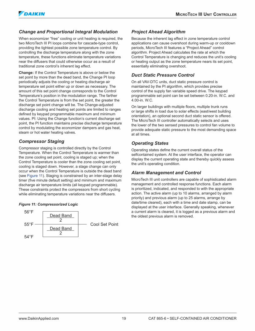
Compressor StagingCompressor staging is controlled directly by the Control Temperature. When the Control Temperature is warmer than the zone cooling set point, cooling is staged up; when the Control Temperature is cooler than the zone cooling set point, cooling is staged down. However, a stage change can only occur when the Control Temperature is outside the dead band (see Figure 11). Staging is constrained by an inter-stage delay timer (five minute default setting) and minimum and maximum discharge air temperature limits (all keypad programmable). These constraints protect the compressors from short cycling while eliminating temperature variations near the diffusers.
Figure 11: Compressorized Logic
Project Ahead AlgorithmBecause the inherent lag effect in zone temperature control applications can cause overshoot during warm-up or cooldown periods, MicroTech III features a “Project Ahead” control algorithm. Project Ahead calculates the rate at which the Control Temperature is changing and reduces the unit’s cooling or heating output as the zone temperature nears its set point, essentially eliminating overshoot.
Duct Static Pressure ControlOn all VAV-DTC units, duct static pressure control is maintained by the PI algorithm, which provides precise control of the supply fan variable speed drive. The keypad programmable set point can be set between 0.20-in. W.C. and 4.00-in. W.C.
On larger buildings with multiple floors, multiple trunk runs or large shifts in load due to solar effects (east/west building orientation), an optional second duct static sensor is offered. The MicroTech III controller automatically selects and uses the lower of the two sensed pressures to control fan volume to provide adequate static pressure to the most demanding space at all times.
Operating StatesOperating states define the current overall status of the selfcontained system. At the user interface, the operator can display the current operating state and thereby quickly assess the unit’s operating condition.
Alarm Management and ControlMicroTech III unit controllers are capable of sophisticated alarm management and controlled response functions. Each alarm is prioritized, indicated, and responded to with the appropriate action. The active alarm (up to 10 alarms, arranged by alarm priority) and previous alarm (up to 25 alarms, arrange by date/time cleared), each with a time and date stamp, can be displayed at the user interface. Generally speaking, whenever a current alarm is cleared, it is logged as a previous alarm and the oldest previous alarm is removed.

CAT 865-6 • SELF-CONTAINED AIR CONDITIONER 20 www.DaikinApplied.com
mICroTeCh III unIT ConTroller
Alarm PriorityThe various alarms that can occur are prioritized according to the severity of the problem. See Table 1. Three alarm categories are used: faults, problems, and warnings.
1. Faults are the highest priority alarms. If a fault condition occurs, the complete unit shuts down until the alarm condition is gone and the fault is manually cleared at the keypad. A fault example is Fan Fail alarm.
2. Problems are the next lower priority to alarms. If a problem occurs, the complete unit does not shut down, but its operation is modified to compensate for the alarm condition. A problem automatically clears when the alarm condition that caused it is gone. Compressor Fail is an example of a problem where only the affected compressor is shut down.
3. Warnings are the lowest priority alarms. No control action is taken when a warning occurs; it is indicated to alert the operator that the alarm condition needs attention. To make sure that they are read, the operator must manually clear all warnings. Dirty Filter indication is an example of a warning.
Generally, a specific alarm condition generates an alarm that falls into only one of these categories. Under different sets of circumstances, however, the freezestat and most of the sensor failure alarm conditions can generate alarms that fall into multiple categories.
Adjustable Alarm LimitsFour alarm indications have adjustable limits that are used to trigger the alarm. The high return temperature alarm and the high and low supply temperature alarms are adjusted at the user interface. The dirty filter alarm(s) is adjusted at the sensing device.
Table 1: MicroTech III Alarm SummaryAlarm Name Fault Problem Warning
Freeze X XSmoke X
Temperature Sensor Failure X XDuct High Limit X
High Return Temperature XHigh Discharge Temperature XLow Discharge Temperature X
Fan Failure XFan Retry X
Discharge Air Capacity Feedback XEconomizer Stuck X X
Auxillary Control Board Enabled XLow Airflow X
Circuit 1–8 High Pressure XCircuit 1–8 Low Pressure/Frost X
Compressor 1–8 Motor Protection XCompressor 1–8 Failure X
Airflow Switch (False Airflow) XDirty Filter X

applICaTIon ConsIderaTIons
www.DaikinApplied.com 21 CAT 865-6 • SELF-CONTAINED AIR CONDITIONER
applICaTIon ConsIderaTIons
The following section contains basic application and installation guidelines which must be considered as part of the detailed analysis of any specific project.
GeneralUnits are intended for use in normal heating, ventilating and air conditioning applications. Consult your local Daikin sales representative for applications involving operation at high entering condenser water temperatures, high altitudes, non-cataloged voltages and for applications requiring modified or special control sequences. Consult your local Daikin sales representative for job specific unit selections that fall outside of the range of the catalog tables, such as 100% outside air applications. For proper operation, rig units in accordance with instructions stated in IM 709. Factory check, test and start procedures must be explicitly followed to achieve satisfactory start-up and operation (see IM 709).
Many self-contained system applications take advantage of the significant energy savings provided by the use of economizer operation. When a water economizer system is used, mechanical refrigeration is typically not required below an entering condenser water temperature of 55°F. Standard Daikin self-contained systems are designed to operate with entering water temperatures down to 50°F when a water economizer is used and 55°F with no water economizer. For applications where a water economizer system cannot be used, a modulating head pressure control system is available to permit operation at entering condenser water temperatures below 55°F.
Unit LocationMake sure that the floor is structurally strong enough to support the unit with minimum deflection (See Unit Weights on page 452). Provide proper structural support to minimize sound and vibration transmission. A concrete floor should be considered. Extra caution is required when installing on a wooden structure. Units must be installed level from front-toback and over their length.
Unit fresh air intakes must be located away from building flue stacks, exhaust ventilators and areas containing automotive or other exhaust to prevent the possible introduction of contaminated air to the system. Consult code requirements for minimum fresh air volumes.
Allow sufficient space around the unit for service and maintenance clearance. Refer to Figure 12 for recommended service/maintenance clearances. See also Recommended Clearances on page 22. Locate equipment room access doors in a manner that can assist in service access if needed (i.e., coil removal). Contact your local Daikin sales representative if reduced service/maintenance clearances are required.
Where code considerations, such as the NEC, require extended clearances, they take precedence over minimum service/maintenance clearances.
Acoustical ConsiderationsGood acoustical design is a critical part of any successful installation and should start at the earliest stages in the design process. Each of the four common sound paths must be addressed. These are: (1) radiated sound through the casing of the unit, (2) structure borne vibration, (3) airborne sound through the supply air duct and (4) airborne sound through the return air duct.
Some basic guidelines for good acoustic performance include:
1. Always provide proper structural support under the unit.
2. Provide adequate mass in the floor structure, especially when located over an occupied space where good acoustics are essential.
3. Seal all supply and return air duct penetrations once the duct is installed.
4. Don’t overlook the return air path. Always include some duct work (acoustically lined tee) at the return inlet.
5. Minimize system static pressure losses to reduce fan sound generation.
6. Select the appropriate unit/fan for the application. Fans should be selected as close as possible to their peak static efficiency. To assist you, peak static efficiency is identified by the first system curve to the right of the shaded “Do not select” region on each fan curve.
7. Design duct systems to minimize turbulence.
8. Account for low frequency duct breakout noise in system design. Route the first 20' of rectangular duct over non-sensitive areas and avoid large duct aspect ratios. Consider round or oval duct to reduce breakout.

CAT 865-6 • SELF-CONTAINED AIR CONDITIONER 22 www.DaikinApplied.com
applICaTIon ConsIderaTIons
Recommended ClearancesFor good installation, service and maintenance access, follow recommended clearances. Minimum clearances required by local, state or federal codes, such as the NEC, take precedence over those listed in Table 2. Clearance is required to allow room for side filter access, mechanical cleaning of condenser tubes and economizer coil access to expansion valves and other control components and to allow for possible fan shaft or compressor removal.
For clearance requirements less than those indicated, consult your local Daikin sales representative.
Table 2: Recommended ClearancesLocation Clearance (inches)Unit Front 42Unit Rear 24Motor Location Side 36Piping Location Side 36Side without Motor or Piping 24Clearance at Face of VFD 42
Figure 12: Recommended Service/Maintenance Clearances
NOTE: 36 inches are required if water and condensate drain connections are left-hand, or fan discharge arrangement is front or upblast CW.
Equipment RoomLocate the equipment room away from sound sensitive areas. Whenever possible, isolate the equipment room from these areas by locating rest rooms, utility rooms, stairwells, hallways, elevators, etc., around its perimeter. This allows not only isolation from radiated sound but provides the capability to route ductwork over less sensitive areas.
Acoustically seal the equipment room. All equipment room penetrations should be sealed with a high quality, flexible material to prevent air and noise from escaping. Even a small leak will compromise the acoustic performance of the installation. The equipment room door should seal tightly on a perimeter gasket.
Equipment room wall construction should be concrete block or offset, double stud. The decision will depend on the critical nature of the application. If offset, double stud construction is used the cavity should be lined with glass fiber insulation and a double layer of sheetrock used on each side of the wall.
DuctworkFan noise can be carried through the ductwork to occupied spaces and likely will be the most challenging to control. Careful duct design and routing practice is required. The ASHRAE Applications Handbook discusses sound attenuation relevant to self-contained system applications. Contact your local Daikin sales representative for sound power data for designing the appropriate sound levels for your specific application.
Return DuctThe return duct is the most often over looked. Return air can be ducted directly to the unit or ducted into the equipment room. If ducted to the equipment room, an elbow should be installed within the equipment room. Running a return air drop near to the floor of the room will provide added attenuation. A length of lined ductwork should extend from the equipment room to a length of 15 feet. The maximum recommended return air duct velocity is 1000 feet per minute.
Supply DuctA lined section of supply air duct should extend at least 15 feet from the equipment room. The use of round duct should be reviewed as it will significantly reduce low frequency sound near the equipment room. If rectangular duct is used, the aspect ratio of the duct should be kept as small as possible. The large flat surfaces associated with large aspect ratios will transmit sound to the space and the potential for duct generated noise, such as oil canning, is increased. The maximum recommended supply air duct velocity is 2000 feet per minute.
When direct ducting to the fan outlet, a minimum of two fan diameters from the fan outlet is recommended and the elbow should turn in the direction of fan rotation. Abrupt turns, takeoffs, etc., will generate air turbulence and resulting unwanted sound
Airflow 24"
42"
Evaporator Coil
Compressors36"24"
or36"
1111 3 4 2AFD
Front
RightSide
CondenserCleanout
Electrical Panel
LeftSide
Back
(See Note )
Motor(See Note)
Motor(See Note)

applICaTIon ConsIderaTIons
www.DaikinApplied.com 23 CAT 865-6 • SELF-CONTAINED AIR CONDITIONER
Duct ProtectionAn adjustable duct high limit switch is standard equipment on all SWT system’s with VAV controls. This is of particular importance when fast acting, normally closed boxes are used. The switch is field adjustable and must be set to meet the specific rating of the system ductwork.
Vibration IsolationDuct connections to the unit or to the acoustic discharge plenum should be made with a flexible connection. Flexible piping and electrical connections should not be required, but attention should be paid to these areas to avoid vibration transmission from outside sources to the SWT unit.
Condenser Water PipingAlways follow good industry practice in the design of the water piping system. Attention to water treatment and proper strainer application are always necessary. All SWT systems feature mechanically cleanable condensers and optional waterside economizer coils. In addition to mechanically cleanable heat exchangers, cleanouts are provided in the interconnecting piping and in the internal condensate drain trap. Costly field traps are not required. To allow periodic cleaning of the condensers and economizer coils, isolation valves should be provided. Condensers, economizer coils and hot water coils are provided with vent and drain connections.
Always review for possible requirements for condenser piping insulation, especially if cold entering condenser water conditions (<55°F) will be experienced.
Head Pressure ControlIf cold entering condenser water conditions (<55°F) will be experienced, a waterside economizer or a condenser head pressure control valve is required. A 2-way, head pressure activated control valve is available factory installed for these applications. A head pressure control valve is not required when the SWT unit is applied with factory waterside economizer package.
Variable Air VolumeVariable frequency drives offer reliable speed control over a wide range of airflow, with advantages in sound and energy performance. In addition, Daikin offers the ability to sense duct static pressure in multiple locations, enhancing control accuracy and helping minimize energy use.
Variable Frequency DrivesVariable frequency drives provide the most efficient means of variable volume control by taking advantage of the fan law relation between fan speed (rpm) and fan brake horsepower (bhp). Also, since airflow reduction is accomplished by changing fan speed, the noise penalties often associated with mechanical control devices, e.g. inlet vanes, are not introduced. The following equation illustrates how fan bhp varies as the cube of the change in fan speed:
In an ideal system, at 50% fan speed, brake horsepower would be reduced to 12.5% of that at full speed.
Variable frequency control varies the speed of the fan by adjusting the frequency and voltage to the motor. Keeping a constant volts/frequency ratio (constant magnetic flux) to the motor allows the motor to run at its peak efficiency over a wide range of speeds and resulting fan airflow volumes.
Duct Static Pressure Sensor Placement The static pressure should be sensed near the end of the main duct trunk(s). The MicroTech III static pressure control should be adjusted so that at full airflow all of the terminals receive the minimum static pressure required plus any downstream resistance. Control is to the lowest static pressure set point that will satisfy airflow requirements. Lower static pressure setpoints will reduce fan brake horsepower requirements and fan sound generation.
The static pressure sensor tap should be located in the ductwork in an area free from turbulence effects and at least 10 duct diameters downstream and several duct diameters upstream from any major interference, including branch takeoffs. The SWT MicroTech III control system can receive a second duct static pressure sensor in installations having multiple duct trunks or significantly varying zones. The control logic will maintain static pressure at both sensors.
( )( )3density2
density1
rpm2rpm1
hp2 = hp1

CAT 865-6 • SELF-CONTAINED AIR CONDITIONER 24 www.DaikinApplied.com
applICaTIon ConsIderaTIons
Zone Sensor PlacementPlacement of the zone temperature sensor is extremely important to provide proper and economical operation of the heating and cooling system. It is generally recommended that the space sensor be located on an inside wall (3 to 5 feet from an outside wall) in a space having a floor area of at least 400 square feet. The sensor should not be located below the outlet of a supply air diffuser, in the direct rays of the sun, on a wall adjacent to an unheated or abnormally warm room (boiler or incinerator room), or near any heat producing equipment. Where zone sensor placement is a problem, all SWT zone control systems have, as standard, the capability to use the return air sensor for heating & cooling control.
FiltrationFilters should be routinely replaced to minimize filter loading. As filters get dirty, the filter pressure drop increases, affecting system airflow and energy requirements. Depending on fan type, forward curved or airfoil, this airflow change can be significant. The effect of filter loading is the most critical when using high efficiency filters.
When making a fan selection, a pressure drop component for filters as they get dirty should be included in the system total static pressure. A value midway between clean and dirty filter ratings is recommended. If a minimum airflow is critical, the fan selection should be made using the higher, dirty filter pressure drop value. For VAV systems, consider setting the fan control device such that part of its modulation range can be used to maintain airflow as filters become dirty. Following these recommendations should limit airflow fluctuation as the filters load.
System Operating LimitsSWT units can be applied in a wide range of system needs. High cfm/ton or high/low discharge temperature applications are available. However, for proper system operation, some application limits do apply.
AirflowMaximum cfm limits, based on coil face velocity, are given Table 4 on page 28.
Separate minimum design cfm limits, by unit size, are given in the physical data table for constant and variable air volume applications. Fan modulation should be limited to 40% of the minimum design cfm limit. Minimum airflow conditions are also dependent on fan selection criteria. Contact your Daikin sales representative to answer any questions on minimum airflow capability or for conditions not shown in the catalog.
VAV box minimum airflow settings should correspond with the minimum VAV fan operating point. All units are provided with multi-groove, fixed pitch sheaves. During system air balance, alternate fixed pitch sheaves may be needed to match final system requirements. Alternate sheaves are available from Daikin.
Fan HeatSensible heat gain from the fan, fan motor and drives occurs in all fan systems and its effect must be considered during equipment selection. It is an added load in cooling and an added source when in heating. The majority of the heat gain occurs through the fan itself, as the air is elevated from the low-pressure side to the highpressure side of the fan. Moving the motor out of the air stream has a negligible effect on overall fan heat gain. A unit with higher fan power requirements/higher fan heat will have less net cooling capability and may not have enough left to satisfy system loads.
As a “rule of thumb,” a typical supply fan heat gain is 3°F. However, fan heat gain can be quickly calculated once the fan has been selected and the fan brake horsepower has been determined. Using Figure 13, select your fan brake horsepower on the horizontal axis, move up vertically until you intersect with the heat gain curve and then move horizontally to find the fan heat gain in Mbh.
Figure 13: Fan and Motor Heat Gain
(Fan Heat (Mbh)) Fan Temperature rise = ________________ (1.085 × Fan cfm)
A draw through unit has the fan located after the DX cooling coil. In this arrangement, fan heat is applied as reheat to the cold, conditioned air coming off of the coil. This arrangement will have a lower sensible heat ratio and higher dehumidification capability than a blow through coil arrangement. The discharge temperature available to the supply duct is always the sum of the coil leaving air temperature plus the fan temperature rise. This must be considered when selecting the supply air volume required to satisfy space requirements.
Example: 52°F leaving coil temp. + 3°F fan temp. rise = 55°F discharge air temp.
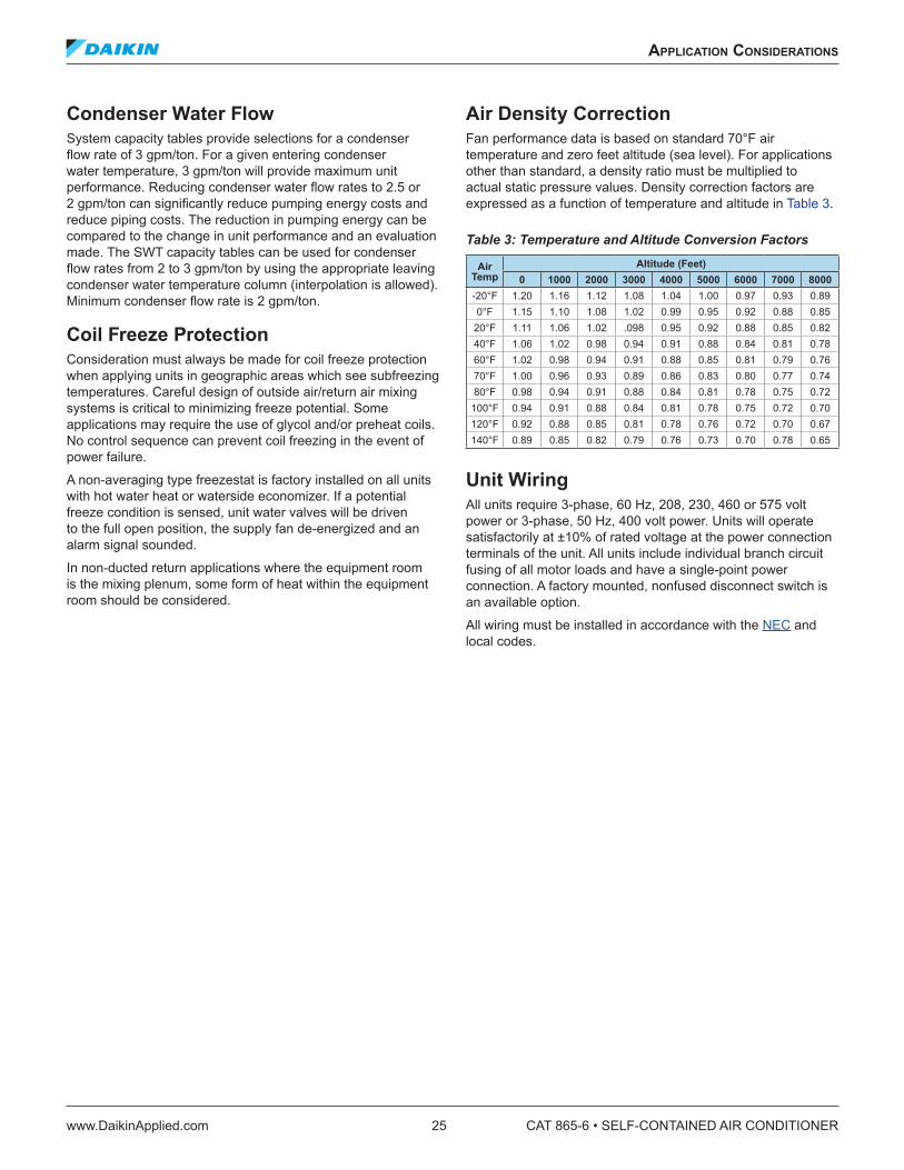
applICaTIon ConsIderaTIons
www.DaikinApplied.com 25 CAT 865-6 • SELF-CONTAINED AIR CONDITIONER
Condenser Water FlowSystem capacity tables provide selections for a condenser flow rate of 3 gpm/ton. For a given entering condenser water temperature, 3 gpm/ton will provide maximum unit performance. Reducing condenser water flow rates to 2.5 or 2 gpm/ton can significantly reduce pumping energy costs and reduce piping costs. The reduction in pumping energy can be compared to the change in unit performance and an evaluation made. The SWT capacity tables can be used for condenser flow rates from 2 to 3 gpm/ton by using the appropriate leaving condenser water temperature column (interpolation is allowed). Minimum condenser flow rate is 2 gpm/ton.
Coil Freeze ProtectionConsideration must always be made for coil freeze protection when applying units in geographic areas which see subfreezing temperatures. Careful design of outside air/return air mixing systems is critical to minimizing freeze potential. Some applications may require the use of glycol and/or preheat coils. No control sequence can prevent coil freezing in the event of power failure.
A non-averaging type freezestat is factory installed on all units with hot water heat or waterside economizer. If a potential freeze condition is sensed, unit water valves will be driven to the full open position, the supply fan de-energized and an alarm signal sounded.
In non-ducted return applications where the equipment room is the mixing plenum, some form of heat within the equipment room should be considered.
Air Density CorrectionFan performance data is based on standard 70°F air temperature and zero feet altitude (sea level). For applications other than standard, a density ratio must be multiplied to actual static pressure values. Density correction factors are expressed as a function of temperature and altitude in Table 3.
Table 3: Temperature and Altitude Conversion Factors
Air Temp
Altitude (Feet)0 1000 2000 3000 4000 5000 6000 7000 8000
-20°F 1.20 1.16 1.12 1.08 1.04 1.00 0.97 0.93 0.890°F 1.15 1.10 1.08 1.02 0.99 0.95 0.92 0.88 0.85
20°F 1.11 1.06 1.02 .098 0.95 0.92 0.88 0.85 0.8240°F 1.06 1.02 0.98 0.94 0.91 0.88 0.84 0.81 0.7860°F 1.02 0.98 0.94 0.91 0.88 0.85 0.81 0.79 0.7670°F 1.00 0.96 0.93 0.89 0.86 0.83 0.80 0.77 0.7480°F 0.98 0.94 0.91 0.88 0.84 0.81 0.78 0.75 0.72
100°F 0.94 0.91 0.88 0.84 0.81 0.78 0.75 0.72 0.70120°F 0.92 0.88 0.85 0.81 0.78 0.76 0.72 0.70 0.67140°F 0.89 0.85 0.82 0.79 0.76 0.73 0.70 0.78 0.65
Unit WiringAll units require 3-phase, 60 Hz, 208, 230, 460 or 575 volt power or 3-phase, 50 Hz, 400 volt power. Units will operate satisfactorily at ±10% of rated voltage at the power connection terminals of the unit. All units include individual branch circuit fusing of all motor loads and have a single-point power connection. A factory mounted, nonfused disconnect switch is an available option.
All wiring must be installed in accordance with the NEC and local codes.

CAT 865-6 • SELF-CONTAINED AIR CONDITIONER 26 www.DaikinApplied.com
seleCTIon proCedure
seleCTIon proCedure
Achieving the optimal performance of any system requires both accurate system design and proper equipment selection. Factors which control unit selection include applicable codes, ventilation and filtration requirements, heating and cooling loads, acceptable temperature differentials and installation limitations. Daikin SWT units offer a wide selection of component options providing the capability to meet diverse application needs.
The Daikin SelectTools™ software selection program allows your local Daikin sales representative to provide you with fast, accurate and complete selection of Daikin SWT units. Unit selection can also be accomplished through reference to physical, performance, dimensional and unit weight data included in this catalog. Due to the variety of cooling system options available, only a sampling of cooling capacity data has been presented in this catalog
Proper equipment selection can be accomplished by following these three simple steps:
1. Select unit size and compressor combination.
2. Selecting heating system.
3. Select fan and motor.
The following example is provided to illustrate the catalog selection procedure.
Selection Example:Scheduled Design Requirements:
Supply air volume. . . . . . . . . . . . . . . . . . . . . . . . . . . .12,000 cfmMaximum face velocity . . . . . . . . . . . . . . . . . . . . . . . . . . 550 fpmSupply fan external SP. . . . . . . . . . . . . . . . . . . . . . . . . .2.0" w.g.Altitude . . . . . . . . . . . . . . . . . . . . . . . . . . . . . . . . . . . . . sea levelVariable air volume system with fan speed controlHot water heatWater economizer system30% pleated filters460V/60Hz/3PhDouble wall constructionStainless steel drain panPremium efficiency motor
Summer Design:
DX coil mixed air dry bulb. . . . . . . . . . . . . . . . . . . . . . . . . . .80°FDX coil mixed air wet bulb . . . . . . . . . . . . . . . . . . . . . . . . . .67°FSensible load . . . . . . . . . . . . . . . . . . . . . . . . . . . .345,000 Btu/hrTotal load . . . . . . . . . . . . . . . . . . . . . . . . . . . . . .450,000 BTU/hr
Winter Design:
Return air temperature . . . . . . . . . . . . . . . . . . . . . . . . . . . . .60°FSpace heating load. . . . . . . . . . . . . . . . . . . . . . . . . . . . 450 mbhEntering hot water temperature . . . . . . . . . . . . . . . . . . . . .180°F
Step 1: Unit Size SelectionUnit size is based on coil face area and cooling capacity requirements. Supply air capacity and maximum face velocity constraints should serve as a guide for selecting coil dimensions and cabinet size.
Based on the given data, the appropriate coil face area may be determined as follows:
Minimum face area = supply air volume/maximum face velocity =12,000 cfm/550 fpm = 21.8 square feet
NOTE: Unit data is based on standard air conditions of 70°F at sea level. See Application Considerations on page 21 for temperature/altitude conversion factors for non-standard conditions.
Referring to Table 4: SWT 018C Through SWT 040C on page 28, the 23.3 square foot coil of the SWT040C satisfies the requirements.
Step 2: Unit DX Cooling SelectionSince the design cfm is less than the nominal value in the DX Cooling Capacity Data table, the capacities must be adjusted. See Table 5: DX Cooling Capacity Correction Multipliers on page 29.
CFM correction factor = Design cfm / nominal cfm = 12,000 / 14,000 = 0.857 Total heat correction multiplier = 0.973 Capacity required from table = 450mbh /.973 = 462.5 mbh Sensible heat correction multiplier = 0.929 Capacity required from table = 345 mbh /0.929 = 371.4 mbh
Using the “DX Cooling Capacity Data” tables provided, the unit selection is a SWT040C with (1) 6 hp and (3) 10 hp compressors. Unit performance from the table equals 512.8 TMBH/375.9 SMBH at 123 gpm. Adjusting for the lower cfm yields:
Total capacity = 512.8 MBH × 0.973 = 499.0 MBH Sensible capacity = 375.9 MBH × 0.929 = 349.2 MBH Coil LAT = 80º F 349.2 MBH / (1.085 × 12,000 cfm) = 53.2°F Condenser flow rate = 123 gpm × 0.973 = 120 gpm

seleCTIon proCedure
www.DaikinApplied.com 27 CAT 865-6 • SELF-CONTAINED AIR CONDITIONER
Step 3: Economizer Capacity SelectionDetermine by referring to the Waterside Economizer Capacity tables on page 32. Use entering air of 80/67°F and entering water of 55°F at 120 gpm. Interpolating for the required gpm, economizer performance equals 276.3 TMBH / 261.9 SMBH at the unit’s nominal cfm. Using the Waterside Economizer Capacity Correction Factors (Table 6 on page 29), performance at the specified cfm can be found.
Total capacity = 276.3 MBH × 0.943 = 260.6 MBH Sensible capacity = 261.9 MBH × 0.904 = 236.8 MBH
Step 4: Heating SelectionDetermine hot water capacity from Table 19 on page 34. After interpolating for the specified cfm, Table 19 indicates a total of 457 mbh.
Step 5: Fan/Motor SelectionFan/motor selection is based on unit total static pressure and design airflow. Total static pressure includes the internal air pressure drops of unit components and external air pressure drops of supply and return air duct systems. See Table 21 on page 35 for internal pressure drops of unit components. Values in the table may be interpolated for the specified cfm.
Internal pressure drops:
DX coil (wet surface) . . . . . . . . . . . . . . . . . . . . . .0.68ʺ w.g. Economizer coil (dry surface) . . . . . . . . . . . . . . .0.38ʺ w.g. Hot water coil . . . . . . . . . . . . . . . . . . . . . . . . . . .0.11ʺ w.g.4ʺ, 30% efficient filters. . . . . . . . . . . . . . . . . . . . .0.19ʺ w.g. Total internal pressure drop. . . . . . . . . . . . . . . . .1.36ʺ w.g.
External pressure drop:
Supply + return duct . . . . . . . . . . . . . . . . . . . . . .2.00" w.g.
Total static pressure = internal drops + external drops = 1.34" + 2.00" = 3.36" w.g.
Entering the fan curve for the SWT040C at 12,000 cfm and 3.75" w.g., yields 13.0 required fan brake horsepower. A 15 horsepower motor can be selected.
Step 6: Calculating Unit WeightReferring to Table 29 on page 45, for a SWT040C:
Unit weight = SWT basic unit + 6 row evaporator coil + economizer coil + water (econ. coil) + hot water coil + water (HW coil) + [(1) 6 hp, (3)10 hp] compressor / condenser + water (condenser) SAF + SAF motor + VFD = 1473 + 450 + 410 + 111 + 152 + 32 + 1233 + 74 + 1120 + 185 + 50 = 5,290 Lbs.
Step 7: Supply Power WiringSizing supply power wire for a unit is based on the circuit with the highest amperage draw. All electrical equipment is wired to a central control panel for either single or optional dual power connections. See Table 23 on page 43 for FLA and RLA ratings. Determine Minimum Circuit Ampacity (MCA) as follows:
MCA = [1.25 × RLA or FLA of largest motor] + [1.00 × RLA or FLA of all other loads] + [2 amps (controls)]
RLA/FLA(1) 6 horsepower compressors . . . . . . . . . .8.1 amps each(3) 10 horsepower compressors . . . . . . . .14.1 amps each15 horsepower premium efficiency supply fan motor . . . . . . . . . . . . . . . . . . . . . . . . 18.9 amps
MCA = [1.25 × 18.9] + [(8.1 + 14.1 + 14.1 + 14.1)] + [2] = 76.0 amps
NOTE: If a unit has been selected with non-concurrent electric heat, MCA must be calculated for both the heating mode and the cooling mode and the larger value used.

CAT 865-6 • SELF-CONTAINED AIR CONDITIONER 28 www.DaikinApplied.com
physICal daTa
physICal daTa
Table 4: SWT 018C Through SWT 040C
DataSWT Model Size
018C 023C 028C 035C 040CCompressorQuantity 4 4 4 4 4Size See DX Cooling Capacity TablesEvaporator CoilFace Area (ft2) 11.8 15.3 18.9 23.3 26.3Rows 4, 6 4, 6 4, 6 4, 6 4, 6Fpi 12 12 12 12 12Performance1
EER / IPLV 13.33 13.95 14.7 13.47 13.27Waterside Economizer CoilFace Area (ft2) 11.8 15.3 18.9 23.3 26.3Rows 4 4 4 4 4FPI 12 12 12 12 12Maximum Working Pressure (psig) 400 400 400 400 400Hot Water Heating CoilFace Area (ft2) 9.3 12.8 16.3 20.2 23.8Rows 1, 2 1, 2 1, 2 1, 2 1, 2Fpi 12 12 12 12 12Electric HeatKw 34 34 34 34 34Filters
(Qty) size (in) 4" depth(3) 20 × 20 (3) 20 × 20 (3) 20 × 20 (5) 20 × 20 (5) 20 × 20(2) 25 × 20 (2) 25 × 20 (2) 25 × 20 (5) 25 × 20 (5) 25 × 20(4) 16 × 25 (4) 16 × 25 (4) 16 × 25 — —
Evaporator Fan2
Quantity 1 1 1 2 2Size 15 18 18 15 15Minimum Horsepower 5 7.5 10 10 15Maximum Horsepower 10 15 20 20 25Minimum Design cfm, CV 2950 3825 4725 5825 6575Minimum Design cfm, VAV 4720 6120 7560 9320 10520Maximum Design cfm 7080 9180 11340 13980 15780CondensersWaterside Working Pressure (psig) 400 400 400 400 400Minimum Entering Temperature (°F) Mechanical Cooling 55 55 55 55 55
Minimum GPM 25 41 53 66 69Maximum GPM 88 108 125 159 1661. Based on ARI 340/360-93 standard rating conditions, 80/67°F to the coil, 85-95° condenser water. 2. Standard fan TSP limit is 5.5 inches of water. Consult your local Daikin sales representative for applications beyond this range.

performanCe daTa
www.DaikinApplied.com 29 CAT 865-6 • SELF-CONTAINED AIR CONDITIONER
performanCe daTa
Unit Efficiency Ratings Correction MultipliersDX Cooling Capacity Correction Multipliers
Table 5: DX Cooling Capacity Correction Multipliers
DescriptionPercent Standard cfm
-20% -15% -10% -5% Std . +5% +10% +15% +20%Total Heat 0.968 0.971 0.985 0.991 1.000 1.006 1.012 1.019 1.025
Sensible Heat 0.900 0.925 0.952 0.974 1.000 1.024 1.048 1.070 1.093Compressor Motor Kw 0.980 0.985 0.989 0.995 1.000 1.004 1.006 1.011 1.017
Waterside Economizer Capacity Correction Factors
Table 6: Waterside Economizer Capacity Correction FactorsCFM Compared To Rated Quantity Total Cooling Capacity Multiplier Sensible Cooling Capacity Multiplier
Waterside Economizer
-20% 0.920 0.870-10% 0.960 0.930STD. 1.000 1.000+10% 1.04 1.06+20% 1.08 1.12
50 HertzFor 50 Hz applications, the total capacity must be derated by 0.89 and the sensible capacity must be derated by 0.94. The 50 Hz supply fan motor horsepower selections must be based on fan brake horsepower (from Figure 20 through Figure 24) divided by 0.8.
DX Cooling Capacity DataSWT023C 8000 CFM
Table 7: SWT023C 8000 CFM (4 Compressors)Compressors EDB(°F) EWB(°F) EWT(°F) TMBH SMBH LDB LWB GPM
(4)6HP
75 6275 298.6 230.4 48.6 48.4 7185 289.3 226.1 49.1 48.9 7095 279.3 221.7 49.6 49.4 70
80 6775 323.3 227.1 54.0 53.8 7685 313.0 223.0 54.4 54.3 7595 302.3 218.7 54.9 54.8 75
85 7275 349.9 223.3 59.4 59.2 8285 339.0 219.4 59.9 59.7 8195 327.5 215.3 60.3 60.2 80
NOTE: See Table 5: DX Cooling Capacity Correction Multipliers on page 29 for determining unit capacity at other than nominal cfm. For a computer generated job specific selection, contact your local Daikin sales representative. For 50 Hz applications, the total capacity must be derated by 0.89 and the sensible capacity must be derated by 0.94. All capacities are gross and do not account for fan motor heat. Altitude and/or Glycol selections also available.

CAT 865-6 • SELF-CONTAINED AIR CONDITIONER 30 www.DaikinApplied.com
performanCe daTa
SWT028C 10,000 CFMTable 8: SWT028C 10,000 CFM (4 Compressors)
Compressors EDB(°F) EWB(°F) EWT(°F) TMBH SMBH LDB LWB GPM
(4) 6HP
75 6275 314.6 261.7 51.0 50.8 7485 304.2 257.1 51.4 51.2 7395 293.7 252.5 51.8 51.6 73
80 6775 339.2 258.0 56.3 56.2 7985 328.3 253.8 56.7 56.6 7995 317.0 249.4 57.1 57.0 78
85 7275 366.3 253.9 61.7 61.6 8585 354.4 249.8 62.1 61.9 8495 342.4 245.6 62.5 62.3 83
Table 9: SWT028C 10,000 CFM (3/1 Compressors)Compressors EDB(°F) EWB(°F) EWT(°F) TMBH SMBH LDB LWB GPM
(3) 6HP, (1) 10HP
75 6275 364.2 283.6 49.0 48.8 8785 352.7 278.4 49.5 49.3 8695 340.5 272.9 50.0 49.8 85
80 6775 394.7 280.0 54.3 54.2 9385 382.1 274.9 54.8 54.7 9295 368.9 269.5 55.3 55.1 91
85 7275 427.8 275.5 59.7 59.6 10085 414.1 270.6 60.2 60.1 9995 399.8 265.5 60.6 60.5 97
SWT035C 12,000 CFMTable 10: SWT035C 12,000 CFM (2/2 Compressors)
Compressors EDB(°F) EWB(°F) EWT(°F) TMBH SMBH LDB LWB GPM
(2) 6HP, (2) 10HP
75 6275 422.1 333.7 49.5 49.3 10085 408.7 327.6 50.0 49.8 10095 394.7 321.4 50.4 50.3 99
80 6775 457.8 329.6 54.8 54.7 10885 443.3 323.8 55.3 55.1 10795 428.0 317.7 55.7 55.6 105
85 7275 496.5 324.6 60.2 60.1 11685 481.0 319.1 60.6 60.5 11495 464.3 313.2 61.1 60.9 113
Table 11: SWT035C 12,000 (1/3 Compressors)Compressors EDB(°F) EWB(°F) EWT(°F) TMBH SMBH LDB LWB GPM
(1) 6HP, (3) 10HP
75 6275 468.6 354.8 47.9 47.8 11285 454.0 348.0 48.4 48.3 11195 438.6 341.0 48.9 48.8 110
80 6775 509.4 350.7 53.2 53.1 12085 493.5 344.1 53.7 53.6 11995 476.6 337.2 54.2 54.1 118
85 7275 553.9 345.6 58.6 58.5 13085 536.7 339.2 59.1 59.0 12895 518.3 332.5 59.6 59.5 127
NOTE: See Table 5: DX Cooling Capacity Correction Multipliers on page 29 for determining unit capacity at other than nominal cfm. For a computer generated job specific selection, contact your local Daikin sales representative. For 50 Hz applications, the total capacity must be derated by 0.89 and the sensible capacity must be derated by 0.94. All capacities are gross and do not account for fan motor heat. Altitude and/or Glycol selections also available.
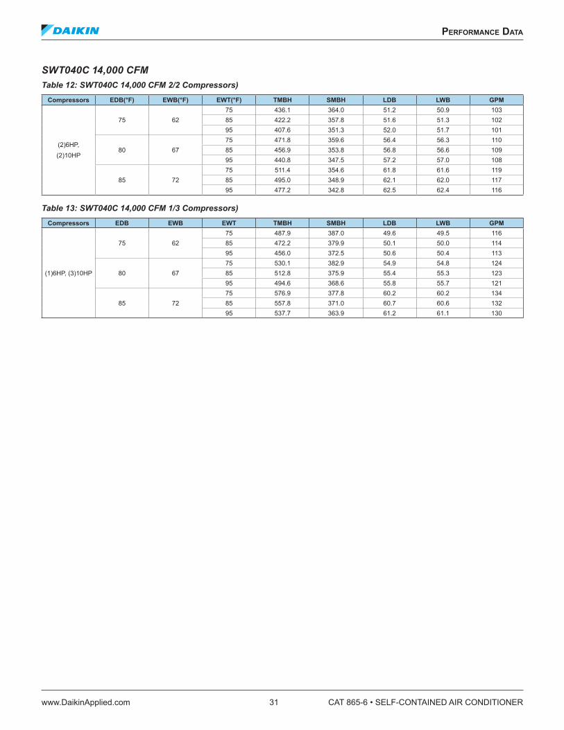
performanCe daTa
www.DaikinApplied.com 31 CAT 865-6 • SELF-CONTAINED AIR CONDITIONER
SWT040C 14,000 CFMTable 12: SWT040C 14,000 CFM 2/2 Compressors)
Compressors EDB(°F) EWB(°F) EWT(°F) TMBH SMBH LDB LWB GPM
(2)6HP, (2)10HP
75 6275 436.1 364.0 51.2 50.9 10385 422.2 357.8 51.6 51.3 10295 407.6 351.3 52.0 51.7 101
80 6775 471.8 359.6 56.4 56.3 11085 456.9 353.8 56.8 56.6 10995 440.8 347.5 57.2 57.0 108
85 7275 511.4 354.6 61.8 61.6 11985 495.0 348.9 62.1 62.0 11795 477.2 342.8 62.5 62.4 116
Table 13: SWT040C 14,000 CFM 1/3 Compressors)Compressors EDB EWB EWT TMBH SMBH LDB LWB GPM
(1)6HP, (3)10HP
75 6275 487.9 387.0 49.6 49.5 11685 472.2 379.9 50.1 50.0 11495 456.0 372.5 50.6 50.4 113
80 6775 530.1 382.9 54.9 54.8 12485 512.8 375.9 55.4 55.3 12395 494.6 368.6 55.8 55.7 121
85 7275 576.9 377.8 60.2 60.2 13485 557.8 371.0 60.7 60.6 13295 537.7 363.9 61.2 61.1 130

CAT 865-6 • SELF-CONTAINED AIR CONDITIONER 32 www.DaikinApplied.com
performanCe daTa
Waterside Economizer CapacitySWT018D 6000 CFMTable 14: SWT018C 6000 CFM
EWT GPM EDB EWB TMBH SMBH LDB LWB LWT
45
3375 62
120.1 118.4 57.0 55.1 52.343 136.0 128.6 55.4 54.2 51.472 163.5 142.7 53.3 52.5 49.539
80 67164.7 135.9 59.3 58.4 53.4
51 187.4 145.3 57.8 57.1 52.485 225.2 160.8 55.5 54.9 50.3
55
2075 62
61.1 61.1 65.7 58.6 61.226 74.2 74.2 63.7 57.8 60.746 92.7 92.7 60.9 56.8 59.026
80 6793.2 93.2 65.8 62.3 62.1
34 106.0 105.9 63.9 61.6 61.259 126.2 120.0 61.7 60.5 59.3
NOTE: See Table 6: Waterside Economizer Capacity Correction Factors on page 29 for determining capacity at other than nominal cfm.
SWT023D 8000 CFMTable 15: SWT023C 8000 CFM
EWT GPM EDB EWB TMBH SMBH LDB LWB LWT
45
4475 62
160.2 157.8 57.0 55.1 52.357 180.9 171.1 55.4 54.2 51.496 216.9 189.6 53.3 52.5 49.552
80 67219.3 180.9 59.3 58.4 53.4
68 249.1 193.3 57.9 57.2 52.4113 298.6 213.5 55.6 55.0 50.3
55
2675 62
81.9 81.9 65.6 58.6 61.335 99.1 99.1 63.7 57.8 60.761 123.2 123.2 60.9 56.8 59.035
80 67124.3 124.3 65.8 62.3 62.1
46 141.0 141.0 63.9 61.6 61.279 167.5 159.5 61.8 60.6 59.3
NOTE: See Table 6: Waterside Economizer Capacity Correction Factors on page 29 for determining capacity at other than nominal cfm.
SWT028D 10,000 CFMTable 16: SWT028C 10,000 CFM
EWT GPM EDB EWB TMBH SMBH LDB LWB LWT
45
5575 62
199.9 196.6 57.0 55.2 52.371 224.4 212.3 55.6 54.3 51.3
120 266.5 234.2 53.6 52.7 49.465
80 67272.7 224.9 59.4 58.5 53.3
85 307.9 239.6 58.1 57.3 52.3142 366.1 263.5 55.9 55.2 50.2
55
3375 62
103.5 103.5 65.5 58.5 61.344 123.9 123.9 63.7 57.8 60.776 152.3 152.3 61.1 56.8 59.044
80 67155.4 155.4 65.8 62.3 62.1
57 175.1 175.1 64.0 61.7 61.198 206.1 197.1 62.0 60.7 59.2
NOTE: See Table 6: Waterside Economizer Capacity Correction Factors on page 29 for determining capacity at other than nominal cfm.

performanCe daTa
www.DaikinApplied.com 33 CAT 865-6 • SELF-CONTAINED AIR CONDITIONER
SWT035C 12,000 CFMTable 17: SWT035C 12,000 CFM
EWT GPM EDB EWB TMBH SMBH LDB LWB LWT
45
6575 62
259.8 249.5 56.0 54.6 52.985 289.9 266.5 54.7 53.6 51.8
144 338.3 290.5 52.9 52.1 49.779
80 67357.0 283.0 58.4 57.7 54.1
101 399.8 300.7 57.1 56.4 52.9170 466.0 327.9 55.0 54.4 50.5
55
3975 62
137.0 137.0 64.6 58.2 62.052 160.6 160.6 62.8 57.5 61.192 192.2 192.2 60.4 56.6 59.252
80 67201.8 201.9 64.6 61.9 62.7
69 223.9 221.9 63.1 61.3 61.5118 261.2 244.9 61.4 60.3 59.4
NOTE: See Table 6: Waterside Economizer Capacity Correction Factors on page 29 for determining capacity at other than nominal cfm.
SWT040C 14,000 CFMTable 18: SWT040C 14,000 CFM
EWT GPM EDB EWB TMBH SMBH LDB LWB LWT
45
7675 62
303.4 291.4 56.0 54.6 53.099 339.0 311.5 54.7 53.6 51.8
168 396.3 339.9 52.8 52.1 49.792
80 67417.3 330.7 58.4 57.6 54.1
118 467.6 351.4 57.0 56.4 52.9198 545.9 383.6 54.9 54.4 50.5
55
4675 62
159.6 159.6 64.6 58.2 62.061 187.4 187.4 62.8 57.5 61.1
107 224.9 224.9 60.3 56.6 59.261
80 67235.6 235.6 64.6 61.9 62.7
80 261.7 259.3 63.1 61.3 61.5137 305.9 285.7 61.3 60.3 59.5
NOTE: See Table 6: Waterside Economizer Capacity Correction Factors on page 29 for determining capacity at other than nominal cfm.

CAT 865-6 • SELF-CONTAINED AIR CONDITIONER 34 www.DaikinApplied.com
performanCe daTa
Heating Capacity Data
Hot Water Coil Capacity (1 Row)Table 19: Entering Water 180°F and Entering Air 60°F
Unit CFM TMBH LWT LDB GPM
018C4000 191.6 158.1 103.8 187000 241.7 152.4 91.6 18
023C6000 277.9 158.8 102.4 259000 329.7 154.9 93.5 25
028C8000 353.3 159.8 100.4 35
10500 397.1 157.5 94.6 35
035C9000 430.2 158.1 103.7 40
13500 512.3 154.0 94.7 40
040C11000 524.5 158.2 103.6 5016000 621.0 155.2 95.5 50
NOTE: For complete one-row capacity and extended two-row capacity, please contact your Daikin sales representative. Selections based on water, for glycol/water solutions, please contact your Daikin sales representative.
Electric HeatTable 20: SWT018C–040C
208V/60HZ/3PH 230V/60HZ/3PH 400V/50HZ/3PH 460V/60HZ/3PH 575V/60HZ/3PHSWT Unit Size kW MBH FLA kW MBH FLA kW MBH FLA kW MBH FLA kW MBH FLA
018C–040C 27.8 94 77.2 34 116 85.6 25.7 88 37.2 34 116 42.8 34 116 34.2

performanCe daTa
www.DaikinApplied.com 35 CAT 865-6 • SELF-CONTAINED AIR CONDITIONER
Component Pressure DropsTable 21: Unit Air Pressure Drops (inches w.g.)
Unit CFM 4", 30% Filter 4", 65% Filter 4-Row Economizer 6-Row DX 1-Row HW
SWT018C
4500 0.14 0.27 0.28 0.52 0.115000 0.17 0.31 0.34 0.61 0.136000 0.23 0.41 0.46 0.81 0.177000 0.29 0.52 0.60 1.04 0.22
SWT023C
6000 0.15 0.28 0.29 0.54 0.107000 0.19 0.35 0.38 0.69 0.138000 0.23 0.43 0.48 0.85 0.169000 0.28 0.51 0.59 1.03 0.20
SWT028C
8000 0.17 0.31 0.34 0.61 0.119000 0.20 0.37 0.41 0.74 0.13
10000 0.24 0.44 0.49 0.86 0.1611000 0.28 0.50 0.58 1.00 0.19
SWT035C
8000 0.12 0.23 0.23 0.44 0.0810000 0.17 0.32 0.34 0.62 0.1112000 0.23 0.42 0.47 0.83 0.1514000 0.29 0.52 0.61 1.04 0.19
SWT040C
10000 0.14 0.27 0.28 0.52 0.0812000 0.19 0.35 0.38 0.68 0.1114000 0.24 0.44 0.50 0.86 0.1516000 0.30 0.55 0.63 1.05 0.19
NOTE: DX pressure drops are wet coil and economizer are dry coil. All units must have a DX coil pressure drop.
Figure 14: Condenser Water Pressure Drop, SWT 018C through SWT 040C
Figure 15: Economizer System Water Pressure Drop, SWT 018C through 040C
Note: HP = Total unit compressor horsepower.
H( porD er usser
P2
)O
Condenser Flow Rate (gpm)
20 40 60 80 100 200 3003
4
6
8
10
20
40
12 H
P
18 H
P24
HP
28 H
P32
HP
36 H
P40
HP
Note: Includes coil, Control valves, and interconnecting piping.Note: Add this �P to condenser �P to obtain unit �P for pump selection.

CAT 865-6 • SELF-CONTAINED AIR CONDITIONER 36 www.DaikinApplied.com
performanCe daTa
Figure 16: Hot Water Coil Water Pressure Drop (1-row), SWT018C through SWT040C
Figure 17: Water Regulating Valve Pressure Drop
H( porD er usser
P2
)O
Condenser Flow Rate (gpm)
00500101
0.1
1
10
100
0.01
018C - 028C
035C - 040C

performanCe daTa
www.DaikinApplied.com 37 CAT 865-6 • SELF-CONTAINED AIR CONDITIONER
Fan CurvesFigure 18: SWT018C, 15ʺx15ʺ Fan Without Variable Inlet Vanes
Figure 19: SWT018C, 15ʺx15ʺ Fan, with Variable Inlet Vanes
Note: Fan TSP limit is 5.5" of water. Consult your local Daikin sales representative for applications beyond this range.
CFM
0 1000 2000 3000 4000 5000 6000 7000 8000
Sta
ticP
ress
ure
(inch
esof
wat
er)
0.0
0.5
1.0
1.5
2.0
2.5
3.0
3.5
4.0
4.5
5.0
5.5
6.0
10 HP
7.5
5.0
3.0
2.0
1.5
600
700
800
900
1000
1100
1200
1300
1400
1500
1600 RPM
CFM
0 1000 2000 3000 4000 5000 6000 7000 8000
Sta
ticP
ress
ure
(inch
esof
wat
er)
0.0
0.5
1.0
1.5
2.0
2.5
3.0
3.5
4.0
4.5
5.0
5.5
6.0
10 HP
7.5
5.0
3.02.0
1.5600
700
800
900
1000
1100
012 0
1300
1400
1500
1600 RPM

CAT 865-6 • SELF-CONTAINED AIR CONDITIONER 38 www.DaikinApplied.com
performanCe daTa
Figure 20: SWT023C/028C, 18ʺx18ʺ Fan, without Variable Inlet Vanes
Figure 21: SWT023C/028C. 18ʺx18ʺ Fan with Variable Inlet Vanes
Note: Fan TSP limit is 5.5" of water. Consult your local Daikin sales representative for applications beyond this range.
CFM
0 1000 2000 3000 4000 5000 6000 7000 8000 9000 10000 11000 12000
Sta
ticP
ress
ure
(inch
esof
wat
er)
0.0
0.5
1.0
1.5
2.0
2.5
3.0
3.5
4.0
4.5
5.0
5.5
6.0
10.0
7.5
5.0
3.0
2.01.5
600
700
800
900
1000
1100
1200
1300
1400 RPM
15.0
20.0 HP
CFM
0 1000 2000 3000 4000 5000 6000 7000 8000 9000 10000 11000 12000
Sta
ticP
ress
ure
(inch
esof
wat
er)
0.0
0.5
1.0
1.5
2.0
2.5
3.0
3.5
4.0
4.5
5.0
5.5
6.0
10.07.5
5.0
3.02.01.5
600
700
800
900
1000
1100
1200
1300
1400 RPM
15.0
20.0 HP

performanCe daTa
www.DaikinApplied.com 39 CAT 865-6 • SELF-CONTAINED AIR CONDITIONER
Figure 22: SWT 035C/040C. Dual 15ʺx15ʺ Fan, Without Variable Inlet Vanes
Note: Fan TSP limit is 5.5" of water. Consult your local Daikin sales representative for applications beyond this range.
CFM
0 10002000
30004000
50006000
70008000
900010000
1100012000
1300014000
1500016000
1700018000
Sta
ticP
ress
ure
(inch
esof
wat
er)
0.0
0.5
1.0
1.5
2.0
2.5
3.0
3.5
4.0
4.5
5.0
5.5
6.0
10.0
7.5
5.03.02.01.5
600
700
800
900
1000
1100
1200
15.0
20.025.0
30.0 HP
1300
1400
1500
1600 RPM

CAT 865-6 • SELF-CONTAINED AIR CONDITIONER 40 www.DaikinApplied.com
dImensIonal daTa
dImensIonal daTa
Figure 23: Left Side, Front (CW) Discharge Figure 24: Left Side, Back (CCW) Discharge
NOTE: Select unit arrangement on the unit selection.
Table 22: SWT018C 040C DimensionsBasic Unit 018C 023C 028C 035C 040C
A Depth1, 2 52.0 52.0 52.0 52.0 52.0B Lengtha1, 2 84.0 84.0 84.0 100.0 100.0C Height1, 2 112.75 112.75 112.75 112.75 112.75D Fan Discharge 18.62 21.88 21.88 18.62 18.62E Fan Discharge 15.88 18.88 18.88 15.88 15.88F Unit Side to Fan 32.69 31.06 31.06 23.88 23.88G Return Duct Height 45.94 45.94 45.94 45.94 45.94H Return Duct Length 80.0 80.0 80.0 96.0 96.0J Water Out/In (ODS) 2-1/8 2-1/8 2-1/8 2-5/8 2-5/8K Hot Water Out/In (ODS) 1-5/8 1-5/8 1-5/8 1-5/8 1-5/8L To Fan Discharge 2.0 2.0 2.0 6.46 6.46
1. Dimensions do not include lifting lugs, handle, latch, or fastener extensions. 2. For shipping dimensions add 4ʺ (102mm) to depth, 8ʺ (204mm) to length, and 4ʺ (102mm) to height.
3.25
23.5819.33
9.58 18.25 33.75
L
G x HReturn air
FILT
ER
SE
CTI
ON
EC
ON
OM
IZE
R
EVA
PO
RAT
OR
HE
ATE
R
ELE
CTR
ICA
L PA
NE
L
A
Sloped S. S. drain pans
Condenser
Compressor
Sloped S. S. drain pans
3.25
23.5819.33
9.58 18.25 33.75
L
G x HReturn air
FILT
ER
SE
CTI
ON
EC
ON
OM
IZE
R
EVA
PO
RAT
OR
HE
ATE
R
ELE
CTR
ICA
L PA
NE
L
Condenser
Compressor
A
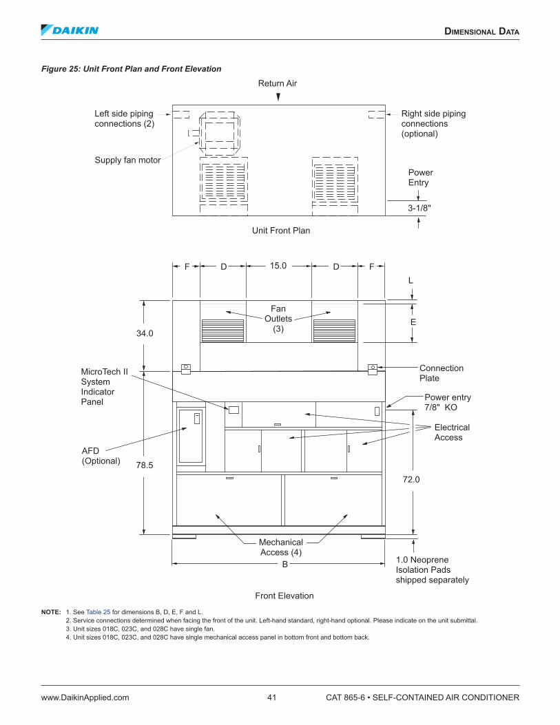
dImensIonal daTa
www.DaikinApplied.com 41 CAT 865-6 • SELF-CONTAINED AIR CONDITIONER
Figure 25: Unit Front Plan and Front Elevation
NOTE: 1. See Table 25 for dimensions B, D, E, F and L. 2. Service connections determined when facing the front of the unit. Left-hand standard, right-hand optional. Please indicate on the unit submittal. 3. Unit sizes 018C, 023C, and 028C have single fan. 4. Unit sizes 018C, 023C, and 028C have single mechanical access panel in bottom front and bottom back.
F FDD 15.0
E34.0
78.5
B
72.0
MechanicalAccess (4)
Power entry7/8" KO
ElectricalAccess
MicroTech IISystemIndicatorPanel
FanOutlets
(3)
1.0 NeopreneIsolation Padsshipped separately
Connection Plate
Return Air
Unit Front Plan
Left side pipingconnections (2)
Right side pipingconnections(optional)
Supply fan motor
Front Elevation
L
PowerEntry
AFD(Optional)
3-1/8"

CAT 865-6 • SELF-CONTAINED AIR CONDITIONER 42 www.DaikinApplied.com
dImensIonal daTa
Figure 26: Back Elevation and Left Side (typical SWT018C 040C)
NOTE:1. Filters are removable from the rear of the unit or through a side filter access door, located on piping connection side.2. Length will be increased by approximately 3-1/2ʺ, for piping connections when water economizer option is ordered3. Mechanical access panels(s) in the back of the unit start 2ʺ below return duct opening. Do not obstruct the access panel(s).4. There are two access doors on 018C, 023C, and 028C instead of three as shown.5. All dimensions are given in inches.6. All dimensions are ±0.25ʺ.
Mechanical access
Connectionplate
2.0 TYPG x H
Return air opening
Mechanical access (3) (4)
26.63
1.0 NeopreneIsolation padsshipped separately
C
B(2)
Back Elevation
23.81
(K) Hot Water Out(K) Hot Water In
10.38
A A
36.5
MainLifting rod(by others)Place throughbase channel
Filter/watereconomizer
1.12 ODS drain
(J) Water out
(J) Water in
G x HRetun air
Left Elevation
Main and filter/watersideeconomizer connection
Section A-A
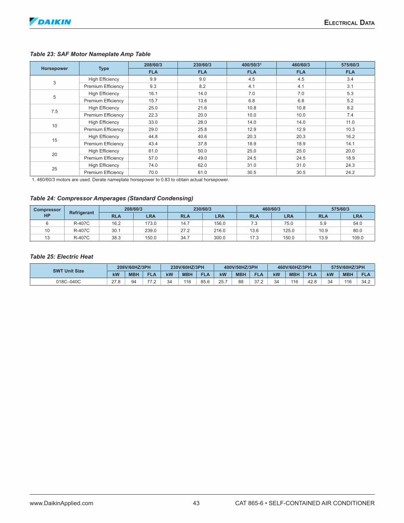
eleCTrICal daTa
www.DaikinApplied.com 43 CAT 865-6 • SELF-CONTAINED AIR CONDITIONER
eleCTrICal daTa
Table 23: SAF Motor Nameplate Amp Table
Horsepower Type208/60/3 230/60/3 400/50/31 460/60/3 575/60/3
FLA FLA FLA FLA FLA
3High Efficiency 9.9 9.0 4.5 4.5 3.4
Premium Efficiency 9.3 8.2 4.1 4.1 3.1
5High Efficiency 16.1 14.0 7.0 7.0 5.3
Premium Efficiency 15.7 13.6 6.8 6.8 5.2
7.5High Efficiency 25.0 21.6 10.8 10.8 8.2
Premium Efficiency 22.3 20.0 10.0 10.0 7.4
10High Efficiency 33.0 28.0 14.0 14.0 11.0
Premium Efficiency 29.0 25.8 12.9 12.9 10.3
15High Efficiency 44.8 40.6 20.3 20.3 16.2
Premium Efficiency 43.4 37.8 18.9 18.9 14.1
20High Efficiency 61.0 50.0 25.0 25.0 20.0
Premium Efficiency 57.0 49.0 24.5 24.5 18.9
25High Efficiency 74.0 62.0 31.0 31.0 24.3
Premium Efficiency 70.0 61.0 30.5 30.5 24.21. 460/60/3 motors are used. Derate nameplate horsepower to 0.83 to obtain actual horsepower.
Table 24: Compressor Amperages (Standard Condensing)
Compressor HP Refrigerant
208/60/3 230/60/3 460/60/3 575/60/3RLA LRA RLA LRA RLA LRA RLA LRA
6 R-407C 16.2 173.0 14.7 156.0 7.3 75.0 5.9 54.010 R-407C 30.1 239.0 27.2 216.0 13.6 125.0 10.9 80.013 R-407C 38.3 150.0 34.7 300.0 17.3 150.0 13.9 109.0
Table 25: Electric Heat
SWT Unit Size208V/60HZ/3PH 230V/60HZ/3PH 400V/50HZ/3PH 460V/60HZ/3PH 575V/60HZ/3PH
kW MBH FLA kW MBH FLA kW MBH FLA kW MBH FLA kW MBH FLA018C–040C 27.8 94 77.2 34 116 85.6 25.7 88 37.2 34 116 42.8 34 116 34.2

CAT 865-6 • SELF-CONTAINED AIR CONDITIONER 44 www.DaikinApplied.com
eleCTrICal daTa
Supply Power Wiring1. Units require three-phase power supply.
2. Allowable voltage tolerances:
a. 60 Hertz
i. Nameplate 208V: Min. 187V, Max. 229V ii. Nameplate 230V: Min. 207V, Max. 253V iii. Nameplate 460V: Min. 414V, Max. 506V iv. Nameplate 575V: Min. 518V, Max. 632
b. 50 Hertz
i. Nameplate 400V: Min. 342V, Max. 418V
3. Power lead wire sizing:
a. For units with cooling capability (all concurrent loads) with or without hot water heating and circuits with motor loads only:
MCA = 1.25 (largest motor RLA or FLA) + other loads + 2 amps
b. For units with cooling capability and non concurrent electric heat capability:
In the cooling mode, the loads will be composed of supply fan motor and compressors. In heating mode, the loads will be compose of supply fan motor and electric heater. The MCA is calculated for unit running in either mode; the highest value obtained is used for the MCA.
i. For unit in cooling mode:
MCA = 1.25 (largest RLA or FLA) + other loads + 2 amps
ii.For unit in heating mode:
MCA = 1.25 (electric heat FLA + supply fan motor FLA) + 2 amps
4. Size wires in accordance with Table 310-16 or 310-19 of the National Electrical Code.
5. Wires should be sized for a maximum of 3% voltage drop. See Table 27 and Table 28 for Single Disconnect or Power Block lug sizes.
NOTE: Use copper wire only.
Table 26: Single DisconnectUnit Voltage Size (Amps)
018-028 208/230 225018-028 400/460 100018-028 575 100035-040 208/230 225035-040 400/460 150
035 575 100040 575 150
Table 27: Lug Sizes For Single DisconnectDisconnect Size Lug Size
100 #6-2/0150 #2-3/0225 #3-300 MCM250 #4-350 MCM
Table 28: Lug Sizes For Power BlockUnit Voltage Lug Size
018-040 All #6-400 MCM
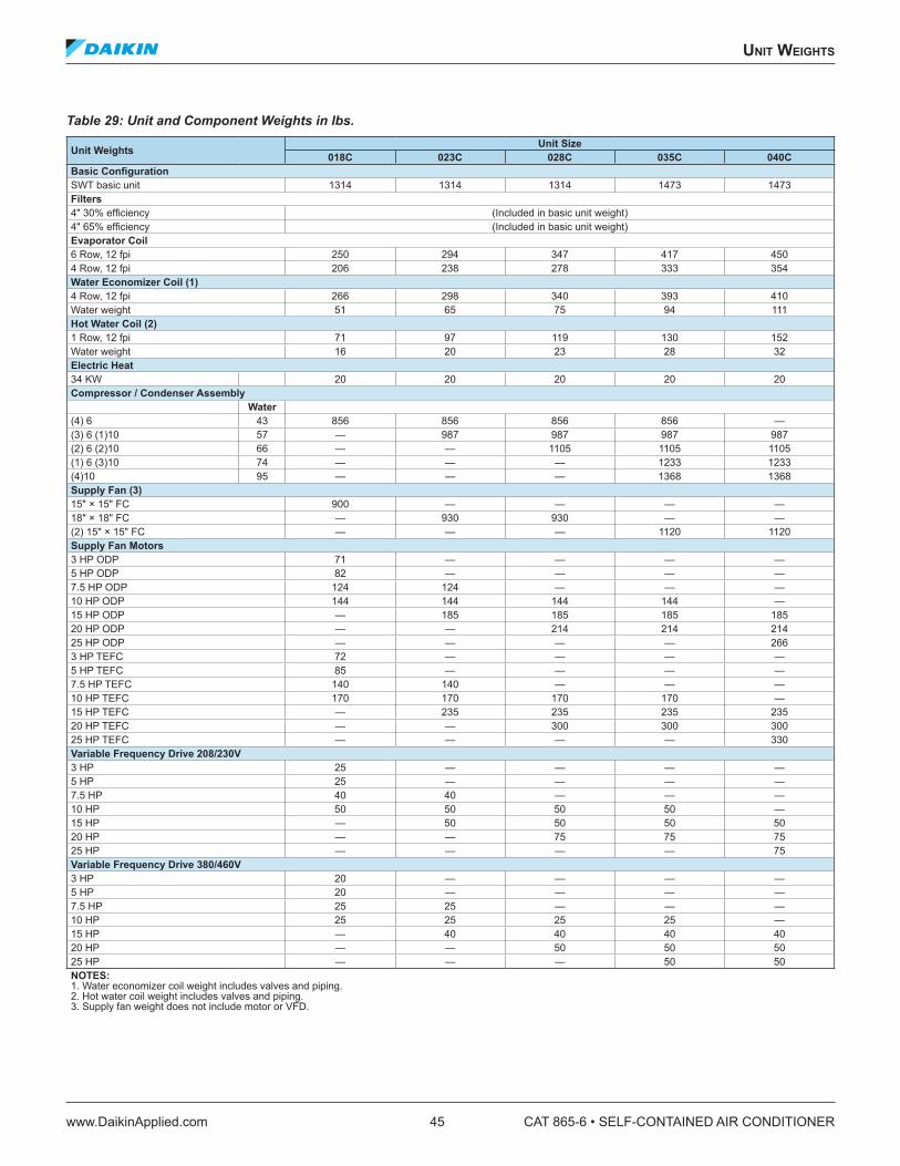
unIT WeIghTs
www.DaikinApplied.com 45 CAT 865-6 • SELF-CONTAINED AIR CONDITIONER
unIT WeIghTs
Table 29: Unit and Component Weights in lbs.
Unit Weights Unit Size018C 023C 028C 035C 040C
Basic ConfigurationSWT basic unit 1314 1314 1314 1473 1473Filters4" 30% efficiency (Included in basic unit weight)4" 65% efficiency (Included in basic unit weight)Evaporator Coil6 Row, 12 fpi 250 294 347 417 4504 Row, 12 fpi 206 238 278 333 354Water Economizer Coil (1)4 Row, 12 fpi 266 298 340 393 410Water weight 51 65 75 94 111Hot Water Coil (2)1 Row, 12 fpi 71 97 119 130 152Water weight 16 20 23 28 32Electric Heat34 KW 20 20 20 20 20Compressor / Condenser Assembly
Water(4) 6 43 856 856 856 856 —(3) 6 (1)10 57 — 987 987 987 987(2) 6 (2)10 66 — — 1105 1105 1105(1) 6 (3)10 74 — — — 1233 1233(4)10 95 — — — 1368 1368Supply Fan (3)15ʺ × 15ʺ FC 900 — — — —18ʺ × 18ʺ FC — 930 930 — —(2) 15ʺ × 15ʺ FC — — — 1120 1120Supply Fan Motors3 HP ODP 71 — — — —5 HP ODP 82 — — — —7.5 HP ODP 124 124 — — —10 HP ODP 144 144 144 144 —15 HP ODP — 185 185 185 18520 HP ODP — — 214 214 21425 HP ODP — — — — 2663 HP TEFC 72 — — — —5 HP TEFC 85 — — — —7.5 HP TEFC 140 140 — — —10 HP TEFC 170 170 170 170 —15 HP TEFC — 235 235 235 23520 HP TEFC — — 300 300 30025 HP TEFC — — — — 330Variable Frequency Drive 208/230V3 HP 25 — — — —5 HP 25 — — — —7.5 HP 40 40 — — —10 HP 50 50 50 50 —15 HP — 50 50 50 5020 HP — — 75 75 7525 HP — — — — 75Variable Frequency Drive 380/460V3 HP 20 — — — —5 HP 20 — — — —7.5 HP 25 25 — — —10 HP 25 25 25 25 —15 HP — 40 40 40 4020 HP — — 50 50 5025 HP — — — 50 50NOTES: 1. Water economizer coil weight includes valves and piping. 2. Hot water coil weight includes valves and piping. 3. Supply fan weight does not include motor or VFD.

CAT 865-6 • SELF-CONTAINED AIR CONDITIONER 46 www.DaikinApplied.com
engIneerIng guIde speCIfICaTIons
engIneerIng guIde speCIfICaTIons
GeneralFurnish and install, as shown on plans, Daikin model SWT selfcontained packaged air conditioning system(s). Unit performance, electrical characteristics and unit arrangement shall be per the job schedule.
[Each unit shall be completely factory assembled and shipped in one piece.] [Each unit shall be shipped in two pieces, a base unit section and the unit fan section.] All units shall be shipped with a full charge of Refrigerant 407C and oil. Unit ratings shall be in accordance with the latest update of ARI Standard 360.
All units shall have decals and tags to indicate caution areas and to aid in unit service. A unit nameplate shall be fixed to a permanent panel next to the main control panel access. Electrical wiring diagrams shall be supplied with each unit. Installation, operating and maintenance bulletins and start-up forms shall be supplied with each unit.
Factory Run TestEach unit shall undergo a rigorous factory run test prior to shipment and factory test sheets shall be available upon request. The factory test shall include dynamic trim balancing of the completed fan assembly, a compressor run check, a complete run test of all electrical components and safeties, including proper control sequencing, a leak check of all refrigerant circuits, a leak check of all water circuits and a final unit inspection.
Safety Agency ListedThe complete unit(s) shall be ETL-US and ETL-Canada listed by Intertek Testing Services, Inc. Units shall conform to bi-national standard ANSI/UL Standard 1995/CSA Standard C22.2 No. 236. Unit(s) shall be accepted for use in the City of New York by the Department of Building, MEA #368-93-E Vol. II.
Cabinet, Casing and FrameEach unit shall have a welded 3/16” structural steel base integrated with formed members of 10, 12 and 14 gauge continuous galvanized steel. Exterior frame and panels shall be constructed of pre-painted galvanized steel for aesthetics and long term durability. Paint finish to include a base primer with a high quality, polyester resin topcoat of a neutral beige color. Finished surface to withstand a minimum 750-hour salt spray test in accordance with ASTM B117 standard for salt spray resistance. Lifting brackets capable of handling the unit shipping weight shall be welded to the unit base with holes to accept cable or chain hooks.
Each unit shall be compartmentalized for ease of service and shall be designed to permit adjustment of system electrical and refrigeration components while the unit is in operation. The unit shall incorporate removable access panels tightly set on neoprene gaskets. Access panels shall be a minimum of 18-gauge galvanized steel and shall be located on all sides of the unit for complete accessibility. The airside cabinet shall be insulated with 1", 1.0 pound density coated glass fiber insulation. [Solid galvanized steel liners shall be provided, allowing no exposed insulation within the air stream.]
The unit shall be comprised of three distinct sections: 1) Main cooling/heating, 2) Filter/waterside economizer and 3) Fan section. Each unit shall be designed for disassembly into the three distinct sections for access to the mechanical equipment room. Disassembly of the unit shall not require the breaking of any refrigeration lines. Separation of water piping shall be through the use of factory installed grooved couplings. The maximum allowable section width, including fastener heads, shall not exceed 34.5 inches.
Filter/Economizer Section:
FiltersEach unit shall be provided with an integral filter section complete with 4" panel filters. The filters shall be removable from the rear of the unit and shall have side access capability through [access panels] [hinged and latched access doors] on each end of the unit. The use of 2" filters is not acceptable.
[4" thick, 30% efficient, UL Std. 900, Class II, AmericanAirFilter filters shall be provided. Filters shall be frame mounted and shall slide into galvanized steel tracks contained within the unit.]
[4" thick, 60-65% efficient, UL Std. 900, Class II, AmericanAirFilter Varicel filters shall be provided. Filters shall be frame mounted and shall slide into galvanized steel tracks contained within the unit.] [An auxiliary pre-filter rack, with 2" thick 30% efficient filters, shall be provided to upstream of the high efficiency filters.]

engIneerIng guIde speCIfICaTIons
www.DaikinApplied.com 47 CAT 865-6 • SELF-CONTAINED AIR CONDITIONER
[4" thick, 80-85% efficient, UL Std. 900, Class II, AmericanAirFilter Varicel filters shall be provided. Filters shall be frame mounted and shall slide into galvanized steel tracks contained within the unit.] [An auxiliary pre-filter rack, with 2" thick 30% efficient filters, shall be provided to upstream of the high efficiency filters.]
Waterside EconomizerA complete waterside economizer package shall be provided including a mechanically cleanable [chemically cleanable] coil, control valves and factory piping complete with cleanouts. Coils shall be fabricated of seamless 1/2" diameter copper tubing that is mechanically expanded into high efficiency aluminum plate fins. Coils shall be a minimum 4-row, staggered tube design with 12 fins per inch. The complete economizer package shall be rated for 400psig waterside working pressure.
The economizer section shall be complete with an insulated stainless steel drain pan. The drain pan shall be sloped in two directions to provide positive drainage. Access panels on both sides of the unit shall provide convenient access to the coil, valves and drain pan for inspection and cleaning. A factory installed drain line, with trap and cleanout, shall be provided for convenient connection at the unit exterior.
Economizer operation shall be controlled to maximize free cooling. Economizer operation shall be enabled whenever the entering water temperature is less than the entering air temperature by a field adjustable value. The economizer control valve shall modulate in response to the cooling load. Control valve operation shall [maintain full flow through the unit at all times.] [isolate the unit from the condenser water loop when there is no call for cooling, allowing for the use of an energy saving, variable pumping system.]
Mechanical cooling shall be enabled during economizer operation. If the economizer control valve is driven 90% open and the cooling load is not satisfied, compressors will stage on to maintain set point. To maximize energy savings, economizer control will maintain full water flow until the differential between entering water and entering air temperatures falls below set point.
A factory installed, non-averaging type freezestat shall provide some protection against coil freeze-up.
The completed economizer assembly shall be factory leak tested.
Airside Economizer Control (External Mixing Box)Integrated airside economizer control capability of a separate unit or remote mounted mixing box shall be provided. Economizer operation shall be controlled to maximize free cooling operation. Economizer shall be enabled whenever the remote [outside air enthalpy sensor] [comparative enthalpy sensors] [outside air temperature sensor] indicates that outside air is suitable for free cooling. The remote economizer damper actuator shall modulate in response to the cooling load.
Mechanical cooling shall be enabled during economizer operation. If the outside air damper is driven to 90% open and the cooling load is not satisfied, compressors will stage on to maintain set point. To maximize energy savings, the economizer control will maintain 100% outdoor airflow until disabled by the enthalpy or temperature cutout. Outside air will reset to minimum position at that time.
Fan Section
Fan AssemblyAll fan assemblies shall be statically and dynamically balanced at the factory, including a final trim balance, prior to shipment. All fan assemblies shall employ solid steel fan shafts. Heavy-duty pillow block type, self-aligning, grease lubricated ball bearings shall be used. Bearings shall be sized to provide an L-50 life at 200,000 hours and shall be no smaller than the main shaft diameter. The entire fan, drive and motor assembly shall be mounted on a welded, heavy-gauge tubular steel frame and shall be mounted on [spring isolators] [spring isolators with seismic restraints]. The fan assembly shall further be isolated from the unit with a flexible connection at the fan discharge. Fixed pitch V-belt drives with matching belts shall be provided. V-belt drives shall be selected at [the manufacturer’s standard service factor] [1.5 times fan brake horsepower].
The fan assembly shall feature a gradual expansion, aerodynamic duct outlet to reduce system sound generation.
Fan (SWT018C-028C)The supply air fan shall be a double width, double inlet (DWDI) forward curved centrifugal fan, with hub and shaft secured with mating keyways. The fan wheel and housing shall be constructed from painted steel and shall be Class II construction to satisfy the specified application.
Fan (SWT035C & 040C)The supply air fan system shall be dual, double width, double inlet (DWDI) forward curved centrifugal fans, with hubs and shaft secured with mating keyways. The fan wheels and housings shall be constructed from painted steel and shall be Class II construction to satisfy the specified application.

CAT 865-6 • SELF-CONTAINED AIR CONDITIONER 48 www.DaikinApplied.com
engIneerIng guIde speCIfICaTIons
Fan MotorFan motors shall be heavy-duty 1800 rpm [open drip-proof (ODP)] [totally enclosed fan cooled (TEFC)] type with grease lubricated ball bearings. [Motors shall be high efficiency and meet applicable EPACT requirements.] [Motors shall be premium efficiency.] Motors shall be NEMA, T-frame, Class B. Motors shall be mounted on an adjustable base that provides for proper alignment and belt tension adjustment.
Variable Frequency Drives (SWT18C-040C)An electronic variable frequency drive shall be provided for the supply air fan. Variable frequency drives shall be latest generation pulse width modulation type utilizing IGBT technology. The drive shall be factory installed in a designated location that provides ready access to the drive and does not void unit accessibility. Drives shall meet UL Standard 95-5V and the variable frequency drive manufacturer shall have specifically approved them for plenum duty application. The completed unit assembly shall be listed by a recognized safety agency, such as ETL.
The unit manufacturer shall install all power and control wiring. A manually activated bypass contactor arrangement shall be provided. The bypass arrangement will allow fan operation at full design CFM, even if the drive has been removed for service.
The supply air fan drive output shall be controlled by the factory installed main unit control system and drive status and operating speed shall be monitored and displayed at the main unit control panel. A factory mounted, field adjustable duct high-limit control shall be provided to protect ductwork from excessive duct pressure. The installer shall provide and install sensor tubing from [a single unit mounted pressure sensor] [two unit mounted pressure sensors] to the duct location(s).
All drives shall be factory run tested prior to unit shipment.
Coils
Drain PanThe main coil section shall be complete with an insulated stainless steel drain pan. The drain pan shall be sloped in two directions to provide positive drainage. Access panels on both sides of the unit shall provide convenient access to the coil and drain pan for inspection and cleaning. A factory installed drain line, with trap and cleanout, shall be provided for convenient connection at the unit exterior.
Cooling CoilDirect expansion (DX) cooling coils shall be fabricated of seamless 1/2" diameter high efficiency copper tubing that is mechanically expanded into high efficiency aluminum plate fins. Coils shall be a 6-row, staggered tube design with 12 fins per inch. All units shall have an independent refrigerant circuit per compressor and shall use a combination row/interlaced circuiting for efficient part load operation and to prevent air temperature stratification at partial load conditions. Each circuit shall be fed by an adjustable thermal expansion valve, with external equalizer, sized to provide efficient operation at full and at part load operating points. Plastic sleeves shall protect all distributor tubes.
All coils shall be factory leak tested with high pressure air under water.
Hot Water CoilA 1 row hot water heating coil shall be factory installed. Coils shall be fabricated of seamless 1/2" diameter copper tubing that is mechanically expanded into high efficiency aluminum plate fins. All coil vents and drains shall be factory installed. Access panels shall provide convenient access to the coil and valve for inspection and cleaning.
A factory installed two-way [modulating] [ON/OFF] control valve and actuator shall provide control of the hot water coil. The valve actuator shall be controlled by the factory installed main unit control system.
[Propylene glycol shall be added to the hot water circuit to protect against coil freeze-up.]
[A factory installed, non-averaging type freezestat shall provide some protection against coil freeze-up.]
Coils shall be factory leak tested with high pressure air under water.
Electric HeatStaged electric heating coils shall be factory installed in the unit heat section. Heating coils shall be visible and easily accessed for inspection and service. Heating coils shall be constructed of low watt density, nickel-chromium elements. Equipment protection controls shall include automatic reset high limit control for each heater element with manual reset backup line break protection in each heater element branch circuit. Heating element branch circuits shall be individually fused to a maximum of 48 Amps per NEC requirements.
Multiple full magnetic line break contactors shall be controlled by the factory installed main unit control system to provide multiple stages of control.

engIneerIng guIde speCIfICaTIons
www.DaikinApplied.com 49 CAT 865-6 • SELF-CONTAINED AIR CONDITIONER
CondensersCondensers shall be a counter flow, tube and tube design with all nonferrous water channels. Each condenser shall be on an independent refrigerant circuit and shall provide liquid sub-cooling for optimum system performance. Condensers shall be rated for 400psig refrigerant working pressure. Each condenser shall be suitable for 400psig waterside working pressure and shall be mechanically cleanable. All factory piping shall be capable of a waterside working pressure of 400 psig. Condensers shall be factory piped to provide for single field condenser water supply and return connections.
Units provided with condensers that are not mechanically cleanable will not be acceptable.
Condensers shall be factory leak tested with high pressure air under water. The completed condenser and interconnecting piping assembly shall be factory leak tested.
Condenser head pressure control (Not available with Water Economizer)Mechanical cooling shall be available whenever entering condenser water temperatures are 55ºF or warmer, without the use of head pressure control. For entering condenser water temperatures below 55ºF, a factory installed and controlled 2-way modulating head pressure control valve shall be provided. The valve actuator shall be controlled through the factory installed main unit control system to maintain refrigerant head pressure at entering condenser water temperatures as low as 40°F.
CompressorsEach unit shall have multiple, heavy-duty scroll compressors. Each compressor shall be on an independent refrigerant circuit and include [suction and discharge service valves with gauge ports], sight-glass, anti-slug protection, motor overload protection and a time delay to prevent short cycling and simultaneous starting of compressors following a power failure. Compressors shall be isolated on resilient rubber isolators to decrease noise transmission. The number of compressors shall be as shown on the unit schedule.
Refrigeration ControlsEach unit shall have multiple independent refrigeration circuits. Each circuit shall include a filter-drier, liquid moisture indicator/sight-glass, thermal expansion valve, liquid line shutoff valve with charging port and high pressure relief device. The thermal expansion valve shall be capable of modulation from 100% to 25% of its rated capacity. [Shutoff valves shall isolate each filterdrier and sight-glass. (Units with compressor service valves only.)] Sight-glasses shall be accessible for viewing without disrupting unit operation. Each circuit shall be dehydrated and factory charged with Refrigerant 407C and oil.
Each refrigerant circuit shall have a high and low-pressure cutout switch and a coil frost protection thermostat. The high pressure cutout shall be a manual reset control. Each low pressure control (loss of charge) and frost protection thermostat shall require a manual reset if the alarm condition occurs three times within any 24 hour period.
Refrigeration Capacity ControlRefrigeration capacity control shall be accomplished by staging of the unit’s multiple compressors. To maintain desired temperature control, the unit shall have a minimum of [two] [three] [four] steps of capacity control.
All compressor capacity control staging shall be controlled by the factory installed main unit control system.
ElectricalUnit wiring shall comply with NEC requirements and with all applicable UL standards. All electrical components shall be UL recognized, where applicable. To provide for easy identification, all wiring and electrical components shall be numbered, color-coded and labeled according to the electrical diagrams provided with each unit. The main unit control panel shall be completely factory wired and contained in an accessible enclosure. The main control panel shall be provided with dead front covers over all line voltage components. A terminal board shall be provided for low voltage control wiring. Branch circuit fusing, 115V control circuit transformer with fuse, system switches and high temperature sensor shall also be provided.
Pilot knockouts shall be provided at the main control panel for field wiring entrance. The unit shall have a [single] [dual] [terminal block] [non-fused disconnect] for main unit power connection.
Each compressor shall be controlled by its own dedicated contactor, shall be individually fused and shall have thermal overload protection. The supply fan motor circuit shall include a dedicated contactor, external line break overload protection and dedicated fuse protection. Group fusing of components in lieu of individual fuse protection for each component is not acceptable.

CAT 865-6 • SELF-CONTAINED AIR CONDITIONER 50 www.DaikinApplied.com
engIneerIng guIde speCIfICaTIons
The unit control system shall permit starting and stopping of the unit locally or remotely. The keypad/display and monitoring panel shall include a three position “ON”, “OFF”, “AUTO” switch, an Alarm indication light and a Power indication light. The Alarm light shall provide a visual indication whenever a malfunction occurs and it shall remain until the malfunction is corrected. The control system shall be capable of providing a remote alarm indication. The unit control system shall provide for pump start, outside air damper actuation, smoke shutdown, emergency shutdown, remote heat enable/disable, remote cool enable/disable, heat indication, cool indication, fan interlock and fan operation.
Non-fused Disconnect Switch[A single non-fused disconnect switch shall be provided for disconnecting electrical power at the unit. The switch handle shall be visible, located at the front of the unit, and shall be accessible without unit entrance.]
[Dual non-fused disconnect switches shall be provided for disconnecting electrical power at the unit. One switch will service the supply fan plus the unit control system. The second switch will service the condensing unit section. Disconnect switch handles shall be visible, located at the front of the unit, and shall be accessible without unit entrance.]
Phase Failure/Under Voltage ProtectionA phase failure/under voltage protection device shall be provided to protect three-phase motors from damage due to single phasing, phase reversal and low voltage conditions.
Water Flow SwitchA water flow switch shall be provided, factory installed, to verify water flow status at the unit. Compressor operation shall be disabled and an alarm signal provided if condenser water flow is lost. Unit operation will be restored when water flow has again been sensed. Water flow status shall be displayed at the unit’s main controller.
Freezestat(Units with Waterside Economizer)
A non-averaging type freezestat shall be factory installed on the entering face of the economizer coil. Upon sensing a freeze condition, the unit supply air fan will be shut down, the [economizer] [heating] [economizer and heating] valve will be driven to the full open position and an alarm signal will be provided. Unit operation will be restored following the manual reset of the freezestat.
Freezestat(Units without Waterside Economizer)A non-averaging type freezestat shall be factory installed on the leaving face of the hot water heating coil. Upon sensing a freeze condition, the unit supply air fan will be shut down, the heating valve will be driven to the full open position and an alarm signal will be provided. Unit operation will be restored following the manual reset of the freezestat.
MicroTech III Unit ControllerEach unit shall be equipped with a complete MicroTech III microprocessor based control system. The unit control system shall include all required temperature and pressure sensors, compressor control boards, heating control board, main microprocessor control board and opera-tor interface. The unit control system shall perform all unit control functions including scheduling, [constant air volume, zone temperature control (SCC)] [constant air volume, discharge temperature control (DAC)] [variable air volume, cooling only discharge temperature control [with single-stage morning warm-up heat] (DAC)] [variable air volume, cooling/modulating heating discharge temperature control (DAC)] [duct static pressure control], [building static pressure control], unit diagnostics and safe-ties. All boards shall be individually replaceable for ease of service. All microprocessors, boards, and sensors shall be factory mounted, wired and tested.
The microprocessor shall be a stand-alone DDC controller not dependent on communications with any on-site or remote PC or master control panel. The microprocessor shall maintain existing set points and operate stand alone if the unit loses either direct connect or network communications. The micro-processor memory shall be protected from voltage fluctuations as well as any extended power failures. All factory and user set schedules and control points shall be maintained in nonvolatile memory. No settings shall be lost, even during extended power shutdowns.
The main microprocessor shall support an RS-232 direct connection to a product service tool or a modem. A [BACnet®/IP] [BACnet®MS/TP] [LonTaLk®] communications port shall be provided for direct connection into the BAS network.
All digital inputs and outputs shall be protected against damage from transients or wrong voltages. Each digital input and digital output on the main microprocessor shall be equipped with an LED for ease of service. An alarm LED on the user interface shall provide quick visual identification that an alarm condition exists. All field wiring shall be terminated at a separate, clearly marked terminal strip.
The microprocessor shall have a built-in time schedule. The schedule shall be programmable from the unit keypad interface. The schedule shall be maintained in nonvolatile memory to insure that it is not lost during a power failure. There shall be one start/stop per day and a separate holiday schedule. The controller shall accept up to sixteen holidays each with up to a 5-day duration. Each unit shall also have the ability to accept a time schedule via BAS network communications.

engIneerIng guIde speCIfICaTIons
www.DaikinApplied.com 51 CAT 865-6 • SELF-CONTAINED AIR CONDITIONER
If the unit is to be programmed with a night setback or setup function, an optional space sensor shall be provided. Space sensors shall be available to support field selectable features. Sensor options shall include:
1. Zone sensor with tenant override switch.2. #1 plus a heating and cooling set point
adjustment. (CAV-ZTC only)
The unit keypad/display character format shall be 20 characters × 4 lines. The character font shall be 5 × 8 dot matrix. The display shall be a supertwist nematic (STN) LCD display with black characters on yellow background for high visibility. For ease of service, the display format shall be English language readout. Coded formats with look-up tables shall not be acceptable.
The keypad interface shall be equipped with eight individual touch-sensitive membrane key switches that allow convenient navigation and access to all control functions. All control settings shall be password protected against unauthorized changes.
The user interaction with the display shall provide the following information:
1. Return air temperature2. Supply air temperature3. Outdoor air temperature (opt.)4. Space air temperature (opt.)5. Discharge air temperature6. Entering condenser water temperature7. Leaving condenser water temperature8. Mixed air temperature9. Outdoor enthalpy high/low (opt.)
10. Dirty filter indication11. Airflow verification12. Supply fan status13. Supply vane position/VFD speed indication14. Outside air damper position(opt.)15. Duct static pressure16. Duct static pressure #2 (opt.)17. Building static pressure (opt.)18. Cooling status19. Cooling control method
a. Nearestb. Average
20. Heating status21. Dehumidification status22. Control Temperature (changeover)23. External exhaust fan status (opt.)24. VAV output status25. Fan operation status26. Unit status27. Time schedules28. Up to four active alarms with time and date29. Previous 8 alarms with time and date30. Optimal start31. Purge cycle32. System operating hours
a. Fanb. Coolingc. Individual compressord. Heatinge. Economizerf. Tenant override
g. Dehumidification
The user interaction with the keypad shall provide the following set points as a minimum:
1. Control modesa. Off manualb. Autoc. Heat/coold. Cool onlye. Heat onlyf. Fan only
2. Occupancy modea. Autob. Occupiedc. Unoccupiedd. Tenant override
3. Control temperature (changeover)a. Return air temperatureb. Space temperaturec. Network signald. Outdoor air temp. (VAV w/ mod. heat)
4. Cooling with deadband5. Heating with deadband6. Cooling and heating supply

CAT 865-6 • SELF-CONTAINED AIR CONDITIONER 52 www.DaikinApplied.com
engIneerIng guIde speCIfICaTIons
7. Cooling & heating supply reset optionsa. Return air temperatureb. Outdoor air temperaturec. Space temperatured. Airflow (VAV)e. No resetf. Network signal
g. External (1-5 VDC)8. Temperature alarm limits
a. High supply air temperatureb. Low supply air temperaturec. High return air temperature
9. Lockout controla. Compressor lockoutb. Heat lockout
10. Lead-lag on compressorsa. Autob. Disabled
11. Compressor Inter-stage timers12. Night setback and setup space temp.13. Duct static pressure reset options
a. No resetb. Network
14. Building static pressure (opt.)15. Minimum outdoor airflow reset
a. Percent of CFM capacityb. External reset (1-5 VDC)c. Fixed outdoor damper position
16. Economizer changeovera. Enthalpyb. Dry bulb
17. Current time and date18. Tenant override time19. Occupied/unoccupied time schedules20. One event schedule21. Holiday dates and duration22. Service mode
a. Timers normal (all time delays normal)b. Timers fast (all time delays 20 sec.)c. Mode normal (unit on)
Open Communications ProtocolThe unit control system shall have the ability to communicate to an independent Building Automation System (BAS) through a direct [BACnet®/IP] [BACnet®MS/TP] [LonTaLk®] communications connection.
[BACnet® Communications shall conform to the BACnet® protocol (ANSI/ASHRAE135-2001). A protocol implementation conformance statement (PICS) shall be provided. Multiple units may be connected in a common communications network.]
[Communications shall conform to LonMark® Interoperability Guidelines and shall be certified. Controls shall conform to the [Discharge Air Controller (DAC)] [Space Comfort Controller (SCC)] profile.]
Through communications, the BAS System Integration (SI) contractor shall be capable of interacting with the individual self-contained unit controllers in the following ways:
1. Access to [quantity and description from specification] “read only” variables and [quantity and description from specification] “read & and write” variables.
2. Set the unit’s operating mode.3. Monitor controller inputs, outputs, setpoints,
parameters and alarms.4. Change controller setpoints and configuration
parameters.5. Clear alarms.6. Reset the cooling discharge air temperature
setpoint (DAC units).7. Reset the heating discharge air temperature
setpoint (DAC units with modulating heat).8. Reset the duct static pressure setpoint (DAC
units).9. Set the heat/cool changeover temperature (DAC
units).10. Set the representative zone temperature (DAC
units).
It will be the responsibility of the SI Contractor to integrate the self-contained unit data into the BAS to affect the integrated building control logic and centralized system workstation interface.


Daikin Applied Training and DevelopmentNow that you have made an investment in modern, efficient Daikin equipment, its care should be a high priority. For training information on all Daikin HVAC products, please visit us at www.DaikinApplied.com and click on Training, or call 540-248-9646 and ask for the Training Department.
Warranty
All Daikin equipment is sold pursuant to its standard terms and conditions of sale, including Limited Product Warranty. Consult your local Daikin Applied representative for warranty details. To find your local Daikin Applied representative, go to www.DaikinApplied.com.
Aftermarket Services
To find your local parts office, visit www.DaikinApplied.com or call 800-37PARTS (800-377-2787). To find your local service office, visit www.DaikinApplied.com or call 800-432-1342.
This document contains the most current product information as of this printing. For the most up-to-date product information, please go to www.DaikinApplied.com.
Products manufactured in an ISO Certified Facility.
CAT 865-6 (04/15) ©2015 Daikin Applied | (800) 432–1342 | www.DaikinApplied.com