Embed Size (px)
Citation preview

Proceedings World Geothermal Conference 2005 Antalya, Turkey, 24-29 April 2005
1
Modular Geothermal Plants in Italy: Technical Characteristics and Operation Results
Paolo Santini
General Electric Oil & Gas, Via F. Matteucci 2, 50127 Florence - Italy
Keywords: Turbo-generator, turbine, generator, condenser, non-condensable, multistage centrifugal compressor, Tuscany, Larderello, Amiata, Bagnore, Travale, Gabbro, Molinetto, Monterotondo, interchangeability, modular, standardization, inconel, stellite.
ABSTRACT The paper presents the experience of supplying 6 geothermal power plants in Italy.
The article shows the complete plant philosophy, a description of the equipment supplied and some comments to the main issues that the supplier faced up during the development of the job.
All the plants were specified on a modular basis, in order to reduce the number of differences among the 6 plants. Three size of plant, 10, 20, and 40 MW were standardized, and the proposed steam turbines were of two sizes only. A minimum number of capital spare parts are required to ensure the strategic maintenance of the plants.
In details, the paper places a particular focus on the technical issues that have been faced to find suitable solution for this geothermal scenario.
Starting from the well-proven design criteria, used for standard turbo-generators, new solutions were investigated to this specific application. The aggressive environment led to use special materials for casing, rotor and blading like High Alloy Steel, Stellite coatings and Inconell inlays. Direct contact steam condensers were designed in order to match the highest performance with the specific operating conditions and are fully integrated with the Non-Condensable Gas extraction system. The NCG extraction system is composed of an integrally geared compressor with several impellers and intercooling phases; the compressor is driven by the shaft of the generator. The compressors are sized in compliance to the gas percentage present in each geothermal well.
All the turbo-compressors units have been tested by performance test on site and are actually in operation.
The 6 plants, some of which were supplied on turn-key basis, were successfully completed in a short period thanks to the creation of a dedicated team of job management and to the synergistic co-operation between the supplier and the operating company.
1. PROJECT DESCRIPTION
In December 2000 GE-Nuovo Pignone won a bid issued by ERGA (nowadays Enel GreenPower) for the supply of eight turbo-generator units to be installed in various geo-thermoelectric plants in Tuscany in the areas of Larderello and Monte Amiata. Later on in March 2001 two units were added for Travale and Bagnore plants.
The machinery was ordered both to replace obsolete machinery in existing plants and to create plants that use the fluid of new geothermal basins.
The scope of supply of each turbo generator unit consists of turbine, generator, condenser, non-condensable gas extraction system and control system.
6 plants out of 10 are in operation. One is in construction, the remaining 34 are in the approval process by local authorities.
Turbines are operated with the endogenous fluid conveyed from geothermal wells, consisting in a mixture of steam and non-condensable gas.
The endogenous fluid is a very aggressive fluid: the non-condensable gas is mainly composed by CO2 with H2S up to 5%; the steam contains salts like silicates, sulphates, boric acid and chlorides. Plants with chloride percentage above 2 ÷ 3 ppm, are equipped with steam washing system, installed before the turbine inlet in order to reduce the content of chloride to less than 35 ppm. However when a failure occurs in the washing system, the plant continues to operate without steam washing. Then the endogenous fluid is condensed in a direct contact condenser by spraying cooling water circulated through cooling towers. The cooling water and the condensate are drained from the condenser with the aid of a pump (extraction cycle) or directly into a reservoir positioned at a lower level (barometric cycle). The excess water produced by the cycle is conveyed to re-injection wells. In order to keep the vacuum at turbine exhaust, the non-condensable gases contained in the geothermal fluid are extracted by means of multistage centrifugal compressor with inter-phase cooling due to the very large volume flow. In each plant the vacuum has been optimized to maximize net power output. As a consequence two or three compression phases have been adopted. Inter-phase cooling is achieved in direct contact coolers by cooling tower water. The non-condensable gas is finally delivered to the atmosphere, after H2S abatement when required.
The operation control of Enel GreenPower's Geothermal Plants is performed by remote from a centralized Control

Santini
2
Center in Larderello. The signals are transferred from the local control rooms to Larderello centralized Control Center by means of optical fibres and radio-link; after the start-up the various plants remain unattended.
The flow diagram is shown in figure 1
2. PLANT LAY-OUT
The power generation plants are of three different sizes: 10, 20 e 40 MW.
The nominal flow of the endogenous fluid is respectively 80, 130, and 250 t/h.
Depending on the location of the plant, the pressure at the turbine inlet may vary from a min. of 2 bar up to a max. of 18 bar.
The main characteristics of the plants in operation are shown in table 1
The low pressure of the endogenous fluid makes the turbines large even when the power is relatively small.
The turbine rotors have a diameter of about 1600 mm at the first impulse control stage and about 1100 mm or 1400 mm (depending on the turbine size) at the root of the last stage.
One of the critical aspects of the project was in fact to arrange new machinery of bigger size inside the existing buildings, mainly due to bridge crane height limit.
Turbine, generator and compressor are in single shaft arrangement inside the building, while the condenser is located outside reflecting the typical arrangement of Enel GreenPower’s existing plants.
Another critical aspect was the delivery time and the requirement of putting the plants in operation quickly and in a close sequence.
Maximum uniformity and interchangeability of the single components was also required in order to reduce the number of spare parts and to facilitate maintenance operations of the several units.
Selecting axial exhaust turbines solved the problem of the limited height of the buildings. An additional benefit of this arrangement is the reduction of the exhaust pressure losses, notwithstanding that the arrangement of the condenser was located 90° to the machinery axis. The compressor is driven by the other shaft end of the generator, that in order to facilitate maintenance operation, is mounted on a steel base plate and it can be removed from the machinery line by sliding it on transversal beams.
The general arrangement, similar for all the plants, is shown in figure 2.
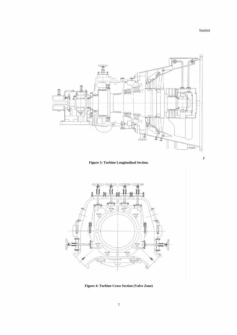
3. GEOTHERMAL STEAM TURBINES
The turbines have a standardized modular design that permits to minimize the number of different components aside from turbine size.
In figures 3 and 4 the typical sections (cross and longitudinal) of the turbines are shown
Great attention was given to the standardization in order to minimize design and manufacturing time. The result of a careful study permitted to adopt a single design for the outer turbine casing of all plant sizes, while the exhaust casing had to be kept different only for 40 MW plant size.
The fluid is fed to two turbine inlet flanges, by means of two trip valves and two control valves. This arrangement permits to exercise the trip valves for free movement check when the turbine is in operation without reducing noticeably the load. In addition to the two automatic control valves, the turbine is provided with 6 manual valves, each one controlling a nozzle segment that contains a different number of nozzles.
For each turbine size a standard steam path has been studied to include maximum nozzle number and maximum stage number.
The turbine rotor has a standard design for each turbine size, but each machine can be equipped with optimum stage number for each installation place. When some stages are not installed, the grooves in the rotor are closed with blade feet (without airfoil) to restore the smooth profile of the rotor surface.
By selecting the appropriate number of nozzles and number of stages, it is possible to get the best turbine performance in each plant, to adjust it when the pressure of the fluid decreases in the well and last but not least to permit easy future use of the turbine in other plants.
The combination of the nozzles per each valve and the number of stages used in the various plants is shown in table 2.
The specific environmental conditions and the presence of H2S demand for a careful selection of the materials
All the turbine components in contact with the endogenous fluid are made of stainless steel and critical surfaces have Inconel inlays.
Turbine blades in the condensing zone are protected with a special stellite coating applied with laser welding.
4. DIRECT CONTACT CONDENSERS
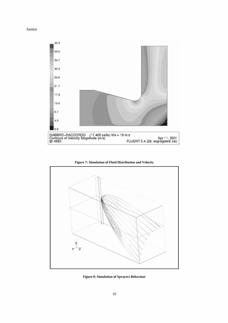
For the condensers the target was to minimize the volume and the weight of the equipment, notwithstanding the huge quantity of cooling water required to perform the steam condensation by direct contact (the cooling water flow is about 50 times greater than the steam flow).
To reduce the volume it is necessary to optimize the distribution of the refrigeration water drops inside the body.
The concept that inspires the design is to split in two parts the equipment: horizontal part to realize the major part of the condensing activity and the vertical part to complete the condensing and to refrigerate the non-condensable gas before its inlet into compressor (see fig. 5 and 6).

Santini
3
The condensing water is sprayed into horizontal part by spray nozzles: the criteria is to optimize nozzles layout by using several down-comers pipes holding the sprayers in the number and position studied to best cover the condensing volume. For this reason the equipment shape that better guarantees the inside volume covering is the prismatic one. The spray nozzles in the vertical part are positioned on horizontal pipes just on the top. The rectangular section allows covering the full volume by uniform spray nozzles layout. The dimensions of the sections are based on the fluid velocity. Computer based models have been developed by Fluent software to optimize shape, dimensions, radius of section junction and check velocity distribution in the sections (see fig. 7 e 8).
The behaviour of the sprayers is tested on several different actual nozzles, in laboratory.
The shape of the water jet, the drops dimensions and distribution, checked in the tests, was modelled by Fluent software to simulate the behaviour of single water spray inside the equipment, with the actual fluid condition, pressure and velocity, considering different nozzle orientation.
The resultant water jet shape, drop velocity, resident time and so on are the base of the final design of size, number and position of the spray nozzles.
A real dimension actual mock up of a condenser has been fabricated and tested to check the design. (See fig. 9).
The concept of weight reduction was to identify the role of the components.
As a sort of membrane a thin stainless steel plate envelopes the body in contact with the fluid to guarantee the corrosion resistance, while the mechanical reinforcement is given by carbon steel external beams verified by Ansys software finite element calculations.
5. MULTISTAGE CENTRIFUGAL COMPRESSORS
The non-condensable gas extractors, used to keep the vacuum in the condensers are geared type centrifugal compressors (see Fig 10). The dimensions change noticeably plant by plant depending on the non-condensable gas quantity associated with the endogenous fluid.
The percent weight flow changes from 1.6% min. in Monterotondo plant to 12% max. in Gabbro plant. As a consequence the first stage at compressor suction has been designed as a single impeller (dia. 600 mm) for Monterotondo, while two impellers (dia. 1150 mm) were required for Gabbro. Absorbed power ranges from 300 kW to 2300 kW.
Special material and design criteria have been adopted due to aggressive gas.
This type of compressors, introduced in geothermal services for the first time at the beginning of the 80s, offers the advantage of high efficiency performances associated with low installation and maintenance costs.
All compressors impellers are three-dimensional open type with blades machined from a solid forging made of ASTM A705 Gr 630 steel.
The inter-phase cooling is achieved by means of direct contact coolers filled with Rashig rings inserted in removable baskets in order to facilitate cleaning during planned maintenance operation.
6. PROJECT EXECUTION
The planning of the projects was based on the provision of start-up of the new units every 15 days with an overall completion time of 21 months.
Great attention was devoted to the organization of a single project team for the six plants, where all disciplines were present (project management, engineering, procurement, construction and logistic). The simultaneousness of projects execution, together with the required uniformity of selected design features was the real challenge for optimizing the resources.
Three units were put in operation by the supplier on turn-key basis, while the remaining three were erected and commissioned by the user with supervision of the supplier.
The project was made difficult also by the location of the plants and the lack of storage areas in proximity of the plants.
Great contribution to attain project’s object was given by:
• standardization
• coordination meetings and “lesson leaned” transfer plant by plant
• agreements with suppliers
• remote transfer of files with vendors and client (Project Net)
• project revision considering exceptional transportation requirements and involving local authorities
• rigorous planning of field activities and special material storage management in a dedicated centralized storage area
7. OPERATION RESULTS
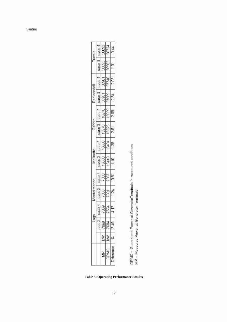
Performance tests were performed in all the plants according to a procedure agreed with the client. The guaranteed power foreseen with max inlet steam conditions and min/max cooling water temperature (case 3 and case 4) was recalculated referring to the measured test conditions.
The results are shown in table 3.
The spread of the results has to be attributed basically to the sensitivity of the unit performance to the several involved parameters.
The interpretation of the overall result is that the actual power is higher than the guaranteed values with zero tolerance giving to the user an extra economic benefit of about 300,000 €/year.

Santini
4
Figure 1: Flow Diagram

Santini
5
Figure 2: Typical Plant Arrangement.

Santini
6
Table 1: Plant Characteristics.
Santini
7
F Figure 3: Turbine Longitudinal Section.
Figure 4: Turbine Cross Section (Valve Zone)

Santini
8
Table 2: Turbine Valves and Nozzles for Geothermal Purpose.

Santini
9
Figure 5: Direct Contact Condenser During Installation
Figure 6: Schematic Lay-Out of Condenser
Santini
10
Figure 7: Simulation of Fluid Distribution and Velocity
Figure 8: Simulation of Sprayers Behaviour

Santini
11
Figure 9: Sprayers Test on a Real Size Model
Figure 10: Four Stages Geared Type Centrifugal Compressor
Santini
12
Table 3: Operating Performance Results